Embed Size (px)
Citation preview

POWER MOLLER®
The Modern Approach to Conveyor Motorization
ITOH DENKI, USA POWER MOLLER
135 Stewart Road • Hanover Industrial Estates • Wilkes-Barre, Pennsylvania 18706-1462Telephone: 570-820-8811 • Facsimile: 570-820-8838 • www.itohdenki.com
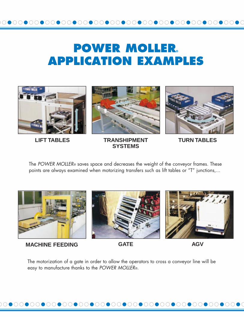
The motorization of a gate in order to allow the operators to cross a conveyor line will beeasy to manufacture thanks to the POWER MOLLER®.
POWER MOLLER®
APPLICATION EXAMPLES
AGVGATEMACHINE FEEDING
TRANSHIPMENTSYSTEMS
TURN TABLESLIFT TABLES
The POWER MOLLER® saves space and decreases the weight of the conveyor frames. Thesepoints are always examined when motorizing transfers such as lift tables or “T” junctions,...

28
For Single Phase
• Built-in DC rectifier.
Wiring for Free Clutch Type with a built-in brakeFor 3-Phase
For Single Phase
• Built-in DC power supply.
Wiring for “One-Touch” TerminalBlock Fitting No. A-800
• Please use 3 parallel wire cable (optional).• In case that the said optional cable is not used, please use
1.25 mm2 (0.18/50) VSF or KIV.HKIV.
Caution:The terminal block fitting No. A-800 cannot be used with any ofIV cable, VF cable, single-cored cable or FCR wiring.
Fig. 1 Fig. 2
Fig. 3 Fig. 4
Connection1. Upon completion of installation of the terminal block fitting, loosen the 2 mounting screws (M3 x 12) to lift the cover open.2. Slit the 3-parallel wire cable as shown in Fig. 2.3. Place the wires in grooves as shown in Fig. 3 and press them firmly so that the jacket of the wires get pierced by the conductive plate.4. When the wires are tight in the grooves, close the terminal cover and tighten the screws.5. When wiring is done, press the clamp button to insert the lead wires into the lead wire insertion holes as shown in Fig. 4.
• When pressing the clamp button, push the lower part of the button.• For smooth insertion of the wires, direct the tips of wires upward.
6. Make sure that the lead wires are pushed in all the way so that the core wires won’t come out.7. Release the clamp buttons and pull the lead wires lightly to confirm that the wires are firmly connected.8. When the direction of Power Moller’s® revolution is necessary to be changed, switch any 2 of 3 wires.
Wires used• Please use the 3-parallel wire cable (optional). (Standard length; 20 m/roll and 200 m/roll)• In case the above-mentioned wire is not used, please use 1.25 mm2 (0.18/50) cable.
ITOH DENKI, USA POWER MOLLER

Diameter Model Description 115V AC 230V AC 460V AC 24V DC Page #Single Phase Three Phase Three Phase
1.50" (38 mm) PM380AS Light Load Transfer 5PM380DS DC Operation 12
1.68" (42.7 mm) PM427AS Light Load Transfer 6
1.91" (48.6 mm) PM486BS Continuous Operation 6PM486FS Brushless DC Operation 12
2.25" (57 mm) PM570AS Continuous Operation 7PM57ODS Economical DC Operation 13PM570AH High Torque (Intermittent) 7PM570BP Max Torque (Intermittent) 7PM570AU Tolerates Accumulation 8PM570AS Slow Speed Transfer 8PM570ES Brushless DC Operation 13
2.38" (60.5 mm) PM605AS Continuous Operation 9PM605DS Economical DC Operation 14PM605AH High Torque (Intermittent) 9PM605BP Max Torque (Intermittent) 9PM605AU Tolerates Accumulation 10PM605AS Slow Speed Transfer 10PM605ES Brushless DC Operation 14
Tapered Models PMT50AS Continuous Operation 11PMT50AH High Torque (Intermittent) 11PMT50BP Max Torque (Intermittent) 11PMT50AU Tolerates Accumulation 11
3.0" (76.3 mm) PM763BS Continuous Duty 15For Belt Conveyors
PM763BC High Torque (Intermittent) 15
4.53" (115 mm) IP-G Mini Belt Drive 16HP-G Conveyor Pulley 16
1
TABLE OF CONTENTS
WARRANTYItoh Denki warrants its Power Mollers to be free from defects in material and workmanship under normal and proper use for a periodof one year starting from the date stamped on the Moller. A copy of this warranty is available upon request.
- Available as standard - Available but please check with an Itoh Representative to review 460/3/60 applications.

ITOH DENKI, USA POWER MOLLE
Working Concept:The turning force of the motor (outer rotor) is transmitted through the shock absorber to the planetary gearing. The planetarygearing drives the inner gear which is affixed to the roller tube. The tube will rotate because the output shaft (stator) is heldstationary by the conveyor frame.
“One-touch” Spring-loaded shaft:The Power Moller’s® spring-loaded attaching shaft enables the unit to be quickly installed or removed without disassembling theconveyor frame.
Built-in Shock Absorber:When articles are transported on roller conveyor lines, they can sometimes encounter a sudden stop, impact or accelerationthat transmits a strong shock to the torque transmission system of the Power Moller®. The shock absorber provides protectionby acting as a slip clutch between the motor and gearbox. The shock absorber is designed to slip at 150% of motor torque andwill not function under normal conditions.
Outer sheath (pipe)Steel withzinc-plated finish Shock absorber Rotor Stator
Inner gear Planetary gear Sun gear
The SolutionTo Your Automation Needs.
In today’s progressive manufacturing and distribution environments, designing conveyor systems canbe a difficult challenge. Complex problems often need to be solved.
Now there is an innovative and advanced engineering solution that meets the demands of a “new age”in production automation and flexibility. The POWER MOLLER® is a self-contained motorized roller thatopens new horizons in handling system design. It’s low profile and ease of installation make it the perfect choice when production efficiency and space savings are required.
2

ITOH DENKI, USA
27
Wiring for PM763BS, HP-G, IP-GFor 3-Phase
• In case the motor turns in reverse to the designated direction,switch the wiring positions of any two (2) of the three (3) wires.
• The direction of motor revolution can be selected either CW orCCW by the main switch.
Single Phase
• Switch the wiring positions of the black and white wires forreversing the motor revolution.
• Since no condenser is contained, mount the one provided asa standard accessory on a frame or a control panel.
Wiring for PM570ES and PM605ES
Wiring to the Connector 1• Put a current of DC24V to 5 and 6.• Contact of 4 and 5 causes the Power Moller® to turn and dis-
connection of the same shuts it down.• Contact of 3 and 5 turns the Power Moller® in CCW direction
and disconnection of the same in CW direction.• The motor speed can be adjusted by turning a volume (VR1);
CCW for acceleration and CW for deceleration.
* For more detailed information, please see the operation man-ual provided with each product.
* The specifications of PCB is subject to change without notice.
Basic Wiring for Power Moller®
with a built-in brakeFor 3-Phase
For Single Phase
• Built-in DC rectifier.
Wiring for built-in brake types ofPM380DS, PM570DS, and PM605DSDC-24V
* Since a motor protection device is provided on the terminal block, pleasenever fail to use the terminal block as shown in the diagram above.
Wiring for Free Clutch TypeFor 3-Phase
YELLOW / GREENGROUND
50KΩ

26
Basic Wiring for Power Mollers®
For 3-Phase
• In case the motor turns in reverse to the designated direction,switch the wiring positions of any two (2) of the three (3) lead wires.
• The direction of motor revolution can be selected in CW orCCW by the main switch.
Model No.’s applicable:PM380AS, PM427AS, PM486BS, PM570AS, PM570AH,PM570BP, PM570AU, PM605AS, PM605AH, PM605BP,PM605AU, PMT50AS.
Wiring MethodsFor Single Phase• Switch the wiring positions of the black and white wires for reverse
revolution.• Since no condenser is built in, mount the one provided as a stan-
dard accessory on a frame or a control panel.
Model No.’s applicable:PM605AS, PM427AS, PM486BS, PM570AS, PMT50AS.
Wiring for PM380DS, PM570DS,and PM605DSDC-24V
• In case the motor turns in reverse to the designated direction,switch the wiring positions of the two (2) lead wires.
• The direction of motor revolution can be selected either CW orCCW by the main switch.
• When the circuit protector provided on the terminal block is acti-vated, fix the trouble and reset. (PM570DS and PM380DS).
No. A-270-GS and A-280-GSModel applicablePM486BS
The PM486BS is supplied with either the A-270-GS (flat on top) or the A-280-GS (point on top) terminal block to match the conveyor frame holedesign.
Each output shaft should be fixed by the applicable fitting. In case outputshaft turns freely it will cause the wires to break.
Hex Flat Up
Hex Point Up
3
ER
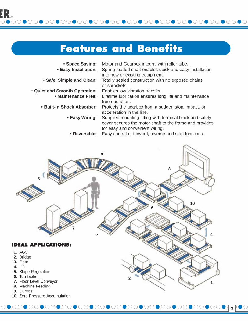
Features and Benefits• Space Saving: Motor and Gearbox integral with roller tube.
• Easy Installation: Spring-loaded shaft enables quick and easy installation into new or existing equipment.
• Safe, Simple and Clean: Totally sealed construction with no exposed chains or sprockets.
• Quiet and Smooth Operation: Enables low vibration transfer.• Maintenance Free: Lifetime lubrication ensures long life and maintenance
free operation.• Built-in Shoc k Absorber: Protects the gearbox from a sudden stop, impact, or
acceleration in the line.• Easy Wiring: Supplied mounting fitting with terminal block and safety
cover secures the motor shaft to the frame and provides for easy and convenient wiring.
• Reversib le: Easy control of forward, reverse and stop functions.
IDEAL APPLICATIONS:1. AGV2. Bridge3. Gate4. Lift5. Slope Regulation6. Turntable7. Floor Level Conveyor8. Machine Feeding9. Curves
10. Zero Pressure Accumulation
12
3
45
6
7
8
9
10

4
ITOH DENKI, USA POWE
LaggingWith waterproof option
Operating voltage: 3 phase 230VRoller tube length: 500mm
Nominal speed: 10m/minAC induction motor, outer rotor design, standard
Roller diameter: 60.5mmPower Moller basic code
Product DesignationAs a nature of motorized roller, Power Moller’s designation consists of both mechanical and electrical elements.The following information is important to determine the right product designation, when you place an order.
1. Mechanical – Roller Tube and Gearbox
2. Electrical – Motor
Roller Diameter Roller Tube GearboxOptionCode Diameter mm (in.) Length mm (in.) Nominal Speed m/min (fpm)
380 38.0 (1.5”) Minimum 200mm (7.87”) Fixed Speed G Rubber lagging427 42.7 (1.68”) up to 1500mm (59.1”) Minimum .07m/min (.23 fpm) NR Natural Rubber486 48.6 (1.91”) with 1mm increment (.04”) up to 60m/min (263.4 fpm) UR Urethane rubber570 57.0 (2.25”) (depending on the model) (depending on the model) CR Neoprene605 60.5 (2.38”) NB NBR-Nitrile763 76.3 (3.0”) OL Other
Motor Type Operating Voltage
1st Specifications 2ndType
1st Power 2nd VoltageCode Code Code Source Code
AAC induction
S Standard 3 AC 3 phase 24 24Vmotor, outer rotor design
BAC induction
H High Torque 1 AC 1 phase 115 115Vmotor, innerrotor design
DDC magnetic U Accumulation D DC 230 230Vmotor
EDC brushlessmotor, outerrotor design
P
FDC brushlessmotor, innerrotor design
See specificmodel foravailablevoltages
Options
Code Description
BR Built-in brake
WA Waterproof (IP-65)
DR Drip proof (IP-55)
DU Dustproof
EC Free-clutch (electrical)
HC Free-clutch (4 mode mechanical)
VP V belt pulley
OS Other specification(s)
Rubber Lagging Designation:
Rubber Material: Lagging diameter: Lagging configuration:lagging NR - Natural rubber 700=70.0mm A - Whole surfacebasic UR - Polyurethane rubber (actual diameter mmx10) B - Each end sectionalcode CR - Neoprene C - Other specification
NB - NBR/NitrileOL - Other
G NR 700 A
Designation Example:
PM 605 AS 10 500 3 230
HighPower
WA GNR700A- - - - - -
460 460V

25
No. A-071-G and A-081-GModel applicablePM486FS
• Supplied as a standard accessory
AccessoriesPM486 series Power Moller is supplied with Driver card No. CB-01 or CB-02 (per customer’s requirements), with a built-in overloadprotection device and potentiometer to vary operating speed, together with two mounting brackets No. A-071-G (flat on top) or A-081-G (point on top) to match the conveyer, design. It is mandatory to fix both shafts of the unit properly with these brackets. Thebase plate of the Driver card must be affixed to conveyor frame to ensure the heat dissipation.
No. CB-02 has two dip switches; Dip switch 1 is for switching internal or externalspeed variation.Dip switch 2 is to preset CW or CCW rotating direction. Normal position is ON.
WIRINGPower: Connect the power source to the terminal 1 and 2. Terminal 1 is for positive 24VDC. Terminal 2 is for 0V.Run/Stop: Run - Closed contact between terminal 2 and 3.
Stop - Open contact between terminal 2 and 3.CW/CCW: CW - Open contact between terminal 2 and 4 (viewed from power cable side)
CCW - Closed contact between terminal 2 and 4 (viewed from power cable side)Note: This holds true when the dip switch 2 on CB-02 is ON.
Error signal: “Low” output in case of overload. (terminal 5 on CB-01, terminal 7 on CB-02)External speed variation: Place a potentiometer between terminal 5 and 6 to vary the motor speed.
Available only with CB-02. Its dip switch 1 must be off to vary the speed externally.Please contact an Itoh Representative f or other driver car ds availab le.
Mounting Bracket No. A-071-G“Hex Flat Up”
Mounting Bracket No. A-081-G“Hex Point Up”
Driver Card No.CB-01
Driver Card No.CB-02
ITOH DENKI, USA POWER MOLLER

24
No. A-800 (Optional)Wiring time is drastically slashed.
• The applicable models are the same as those listed under No. A-200.• Please see page 28 for the wiring procedure.
Advantages• It is not necessary to cut off or strip any wires.• No terminal connection is required, which drastically slashes wiring time.• No slack in wiring.
Order:The fitting No. A-800 is an optional item and no Power Moller® is provided with this fitting as standard.Please order it separately when ordering Power Mollers® and the No. A-800 will be delivered instead ofNo. A-200 at an extra cost.
Terminal Blocks
No. L-200-KModel applicablePM570DS, PM605DS
• Standard terminal block fitting for PM570DS and PM605DS• Please see page for wiring method.
Terminal Bracket No. L-600-FModels applicablePM570ES, PM605ES
The Driver Card No L-600-F has 3 Dip switches:Dip switch 1: to switch internal (VR1) or external speed
variationDip switch 2: to switch manual or automatic recovery of
built-in thermal deviceDip switch 3: to preset CW or CCW rotating direction
PM570/605ES series Power Moller are supplied with No.L-600-F bracket, with a built-in overload protection device.It is mandatory to fix the unit’s output shaft properly with thisbracket. It’s base plate must be affixed to conveyor frame toensure the heat dissipation.

5
PM380AS 1.50" (38mm) Diameter 115V SinglePhase230V Three Phase
StartingPower Speed Tangential Torque No StartSource (ft/min) force (lbs) (In lbs) Load
PM380AS-5 16.4 13.4 10.0
PM380AS-8 24.9 8.9 6.6
PM380AS-10 37.4 5.8 4.3 0.05 0.07
PM380AS-15 52.5 4.9 3.6
PM380AS-20 83.3 3.2 2.4
PM380AS-30 124.3 2.0 1.5
PM380AS-5 16.4 6.8 5.0
PM380AS-8 24.9 4.5 3.4
PM380AS-10 37.4 3.0 2.2 0.11 0.13
PM380AS-15 52.5 2.6 1.9
PM380AS-20 80.1 1.8 1.3
PM380AS-30 124.3 1.1 .8
Specifications
3Phase230VInput12W
Current (A)
SinglePhase115VInput
10.5W
FEATURES:• Designed for slim and compact lines.• Easy installation into existing conveyor lines.• Simplifies new conveyor design.• Easy control of forward, reverse and stop.• Includes No. E-920 Terminal Block.
OPTIONS:
DIMENSIONS:
Standard Product WeightsNominal Tube length L (mm)
MODEL 200 250 300 400 500 600 700 800 900 1000PM380AS .9kg 1.0kg 1.1kg 1.2kg 1.3kg 1.4kg
2.0lb 2.2lb 2.4lb 2.6lb 2.9lb 3.1lbPM427AS 1.1kg 1.2kg 1.3kg 1.4kg 1.6kg 1.7kg 1.9kg 2.0kg
2.4lb 2.6lb 2.9lb 3.1lb 3.5lb 3.7lb 4.2lb 4.4lbPM486BS 1.8kg 1.9kg 2.0kg 2.2kg 2.3kg 2.4kg 2.6kg 2.7kg 2.9kg
4.0lb 4.2lb 4.4lb 4.8lb 5.1lb 5.3lb 5.7lb 5.9lb 6.4lbPM570AS, PM570DS, 1.7kg 2.0kg 2.1kg 2.3kg 2.5kg 2.7kg 2.9kg 3.1kg 3.2kg 3.4kgPM570AH
3.7lb 4.4lb 4.6lb 5.0lb 5.5lb 6.0lb 6.4lb 6.8lb 7.1lb 7.5lbPM570BP, PM570AU,PM570AU
PM763BS 5.4kg 5.9kg 6.8kg 7.7kg 8.6kg11.9lb 13.0lb 15.0lb 17.0lb 19.0lb
Type S Nominal Tube length L (mm)MODEL 195 245 295 395 495 595
PM380DS 0.8kg 0.9kg 1.0kg 1.2kg 1.4kg 1.6kg
1.8lb 2.01lb 2.2lb 2.6lb 3.1lb 3.5lb
Nominal Tube length L (mm)MODEL 290 340 400 500 600 700 800 900 1000PM570AS 2.4kg 2.7kg 2.8kg 3.0kg 3.2kg 3.4kg 3.6kg 3.8kg 4.0kg
SLOW SPEED 5.3lb 6.0lb 5.7lb 6.6lb 7.0lb 7.5lb 7.9lb 8.4lb 8.8lb
PM605AS 3.1kg 3.3kg 3.5kg 4.0kg 4.5kg 5.0kg 5.5kg 6.0kg 6.5kg
SLOW SPEED 6.8lb 7.3lb 7.7lb 8.8lb 9.9lb 11.0lb 12.1lb 13.2lb 14.3lb
1) The “One-Touch” attaching shaft is available on the above models with a minimum 340mm (13.4”).
1) The “One Touch” attaching shaft is available on the above models with a minimum 250mm (9.84”).
Type P Nominal Tube length L (mm)MODEL 200 250 300 400 500 600PM380DS 0.8kg 0.9kg 1.0kg 1.2kg 1.4kg 1.6kg
1.8lb 2.01lb 2.2lb 2.6lb 3.1lb 3.5lb
The inside frame-to-frame dimension (B) ofthe conveyor differs by manufacturer.
Depending on the tolerance of dimension B,the total clearance between dimension Band the total roller length (A) should rangefrom .08” (2mm) to .20” (5mm).
FOR NOMINAL TUBE LENGTHS SEE CHART ABOVE
ER MOLLER

6
FEATURES:• Easy installation into existing • 7/16” Hex Shaft
conveyor lines. • Easy control of forward, reverse, stop.• Simplifies new conveyor design. • Perfect for clean lines.• Includes No. A-270-GS (Flat on top) • Impedance protected motor for
or A-280-GS (Point on top) Terminal Block. accumulation (115V - 230V only).
OPTIONS:
DIMENSIONS:
PM486BS 1.91" (48.6mm) Diameter 115V Single Phase230V Three Phase
StartingPower Speed Tangential Torque No StartSource (ft/min) force (lbs) (In lbs) Load
PM486BS-5 16.4 17.2 16.5PM486BS-10 34.1 9.9 9.5 0.07 0.08PM486BS-15 53.8 6.0 5.8PM486BS-20 67.9 6.0 5.8PM486BS-30 107.6 3.8 3.6 0.04 0.11PM486BS-40 130.2 3.2 3.0PM486BS-5 16.4 7.6 7.3PM486BS-10 34.1 4.5 4.3 0.13 0.17PM486BS-15 53.8 2.9 2.7PM486BS-20 67.9 2.9 2.7PM486BS-30 107.6 1.9 1.9 0.11 0.30PM486BS-40 130.2 1.6 1.5
Specifications
3Phase230VInput12W
Current (A)
FEATURES:• Designed for slim and compact lines.• Easy installation into existing conveyors.• Simplifies new conveyor design.• Easy control of forward, reverse and stop.• Perfect for clean lines.• Includes No. E-920 Terminal Block
OPTIONS:
DIMENSIONS:
PM427AS 1.68" (42.7mm) Diameter 115V Single Phase230V Three Phase
StartingPower Speed Tangential Torque No StartSource (ft/min) force (lbs) (In lbs) Load
PM427AS-5 18.4 11.9 10.0
PM427AS-8 27.9 7.9 6.6
PM427AS-10 42.0 5.2 4.3 0.05 0.07
PM427AS-15 58.7 4.3 3.6
PM427AS-20 89.9 2.8 2.4
PM427AS-30 139.8 1.8 1.5
PM427AS-5 18.4 6.0 5.0
PM427AS-8 27.9 4.0 3.4
PM427AS-10 42.0 2.6 2.2 0.11 0.13
PM427AS-15 58.7 2.3 1.9
PM427AS-20 89.9 1.6 1.3
PM427AS-30 139.8 .9 0.8
Specifications
3Phase230VInput12W
Current (A)
SinglePhase115VInput
10.5W
SinglePhase115VInput
10.5W
FOR NOMINAL TUBE LENGTHS SEE CHART ON PAGE 5
FOR NOMINAL TUBE LENGTHS SEE CHART ON PAGE 5
ITOH DENKI, USA

23
No. D-400-BApplicable ModelsPM380DS
• Standard accessory for PM380DS
• Commonly used for output shaft type S and P.
• A motor protection device is provided on the terminal block.• A safety cover is provided for the terminal block.• Wires should come out of the hole at the bottom of the termi-
nal block for wiring.• Should there be no space for wiring underneath the block,
please make a hole in the side of the block, for which the pro-vision has been provided.
Terminal Blocks
No. E-920Applicable ModelsPM380AS, PM427AS
• Standard accessory for PM380AS and PM427AS.
• Please fix the output shaft by the special fitting. In case theoutput shaft runs freely, it causes the wires to break.
• The wiring method is the same as No. A-200.
Terminal Blocks
No. F-091-B (Optional)
No. F-001-B• Can be mounted on either inside
or outside of a frame.
Brackets
No. F-091-B
No. F-001-B
No. I-210-B Terminal Blocks
• Applicable for the models listed under No. A-200with a dual flat shaft.
• The wiring method is the same as No. A-200.
DENKI, USA POWER MOLLER

22
10) BRAKE INFORMATIONA. In automated conveyor lines, it is sometimes necessary to pre-
cisely stop or position the article being transferred. In thesecases, the optional built-in electro-magnetic brake should beused.
* When not powered, the built-in electro-magnet uses springforce to lock the motor and prevent the tube rotation.The motoris released when the brake is powered (energized). Ordinarily,the power to the brake and motor is controlled simultaneously.
* In most cases, an external mechanical stop can be eliminatedby using the Power Moller® with the built-in brake. However, thestopping distance may vary slightly depending on the load,speed, etc.
B. In gravity lines, it is often necessary to control the descent ofthe load to prevent damage to the articles accumulated at theend of the line. In this case, the standard Power Moller® can act
as a brake roller.* When the rotation speed of the Power Moller® is increased by
10-20% from its nominal speed, it functions as an inductiongenerator and braking torque is applied to the load.
* By incorporating Power Moller®s at several points in a self-traveling gravity line, speeding or congestioning of the loadswill be prevented.
Braking characteristics vary by Power Moller® model and weighttransferred. Please contact your Itoh Denki representative foradditional information.
11) VOLTAGE:The Power Moller® is available in a wide range of single phase andthree phase AC voltages along with 24 DC voltages for usethroughout the world. When ordering, specify the particular volt-age required for your application. Please check with an Itoh Denkirepresentative to review 460/3/60 voltages.
No. A-200Applicable ModelsPM570AS, PM570AH, PM570BP,PM570AU, PM605AS, PM605AH,PM605BP, PM605AU, PMT50AS,PMT50AH, PMT50BP, PMT50AU
• Provided as a standard accessory for each applicable model• Each output shaft should be fixed by the applicable fitting. In case out-
put shaft turns freely, it causes the wires to break.• The mounting hole and stud portion of Fixture 1 are eccentric,
which lets Fixture 2 slide down onto the stud of Fixture 1 to fastenthe output shaft tightly.
Terminal Blocks, Driver Cards, and Brackets
Terminal Blocks
BracketsNo. C-001 • This is used for the frame which does not have enough space
for the No. A-200.• Please specify which one of No. A-200 and No. C-001 is
required for your frame, when ordering. In case that No. C-001is specified, terminal block and safety cover are not included.
No. C-001-D (stainless)• Provided as a standard accessory for water-proof or drip
proof version.
ITOH

7
PM570AS 2.25" (57mm) Diameter 115V Single Phase230V Three Phase
460V Three Phase*
FEATURES:• Designed for continuous and intermittent duty.• Easy installation into existing conveyor lines.• Easy control of forward, reverse and stop.• Not suited for repeated locking.• Includes No. A-200 Terminal Block
OPTIONS:
DIMENSIONS:
PM570AH2.25" (57mm) Diameter230V Three Phase460V Three Phase*FEATURES:• Designed for intermittent duty. • 50% more torque than PM570AS.• Maximum continuous run time • Duty cycle of 50%.
of 20 minutes. • Includes No. A-200 Terminal Block
OPTIONS:
DIMENSIONS: Same as dimensions for PM570AS above.
PM570BP2.25" (57mm) Diameter230V Three Phase
FEATURES:• Designed for intermittent duty. • 150% more torque than PM570AS.• Motor is protected from thermal • Duty cycle of 50%.
overload. • Includes No. A-200 Terminal Block
OPTIONS:
StartingPower Speed Tangential Torque No StartSource (ft/min) force (lbs) (In Lbs) Load
PM570AS-4 14.8 27.9 31.2PM570AS-5 20.3 20.4 22.8PM570AS-8 29.9 14.0 15.7PM570AS-9 37.4 11.1 12.5PM570AS-10 41.0 10.2 11.4PM570AS-13 51.5 8.1 9.0 0.07 0.13PM570AS-15 62.7 7.7 8.6PM570AS-20 86.9 5.4 6.0PM570AS-30 130.6 3.7 4.2PM570AS-45 170.3 2.8 3.2PM570AS-50 188.0 2.5 2.8PM570AS-60 246.7 2.0 2.2PM570AS-4 14.8 11.5 12.8PM570AS-5 20.3 8.4 9.4PM570AS-8 29.9 5.8 6.5PM570AS-9 37.4 4.6 5.1PM570AS-10 41.0 4.2 4.7PM570AS-13 51.5 3.3 3.7 0.17 0.28PM570AS-15 62.7 3.4 3.8PM570AS-20 86.9 2.4 2.7PM570AS-30 130.6 1.7 1.9PM570AS-45 170.3 1.3 1.4PM570AS-50 188.0 1.1 1.2PM570AS-60 246.7 0.9 1.0
Specifications
3Phase230VInput
16.5W
Current (A)
SinglePhase115VInput11W
StartingPower Speed Tangential Torque No StartSource (ft/min) force (lbs) (In Lbs) Load
PM570AH-4 14.8 47.0 52.7PM570AH-5 20.3 34.3 38.5PM570AH-8 29.9 23.5 26.4PM570AH-9 37.4 18.7 21.0PM570AH-10 41.0 17.1 19.2 0.11 0.20PM570AH-13 51.5 13.6 15.2PM570AH-15 62.7 12.9 14.4PM570AH-20 86.9 9.0 10.1PM570AH-30 130.6 6.2 6.9PM570AH-45 170.3 4.7 5.3PM570AH-50 188.0 4.3 4.8PM570AH-60 246.7 3.2 3.6
Specifications
3Phase230VInput20W
Current (A)
StartingPower Speed Tangential Torque No StartSource (ft/min) force (lbs) (In Lbs) Load
PM570BP-4 14.8 71.8 80.5PM570BP-5 21.0 51.5 57.8PM570BP-8 30.2 35.9 40.3PM570BP-10 42.0 25.7 29.0 0.09 0.31PM570BP-15 75.5 16.7 18.7PM570BP-20 117.1 10.8 12.1PM570BP-30 148.6 8.3 9.3PM570BP-40 231.6 5.4 6.0
Specifications
3Phase230VInput20W
Current (A)
DIMENSIONS: Same as dimensions for PM570AS above.
FOR NOMINAL TUBE LENGTHS SEE CHART ON PAGE 5
* Please check with an Itoh Denki representative to review 460/3/60 applications.
POWER MOLLER
* Please check with an Itoh Denki repre-sentative to review 460/3/60 applications.

ITOH D
8
PM570AU 2.25" (57mm) Diameter 230V Three Phase
FEATURES:• For applications requiring extended stall periods.• Special high impedance motor draws low current
under any load condition.• Includes No. A-200 Terminal Block
OPTIONS:
DIMENSIONS: Same as dimensions for PM570AS on page 7.
PM570AS 2.25" (57mm) Diameter 230V Three Phase
FEATURES:• Designed for slow speed transfer.• Useful for inspection and calculating operations.• Wide variation in operating speeds.• Includes No. A-200 Terminal Block
OPTIONS:
DIMENSIONS: Same as dimensions for PM570AS on page 7.
StartingPower Speed Tangential Torque No StartSource (ft/min) Force (lbs) (In lbs) Load
PM570AU-4 13.5 9.9 11.2
PM570AU-5 18.4 7.3 8.1
PM570AU-8 26.9 5.0 5.6
PM570AU-9 33.8 3.9 4.4
PM570AU-10 37.1 3.6 4.1 0.05 0.06
PM570AU-13 46.9 2.8 3.2
PM570AU-15 53.2 2.9 3.4
PM570AU-20 73.2 2.0 2.3
PM570AU-30 113.9 1.4 1.6
PM570AU-45 149.3 1.1 1.2
Specifications
3Phase230VInput8W
Current (A)
StartingPower Speed Tangential Torque No StartSource (ft/min) Force (lbs) (In lbs) Load
PM570AS-0.07 0.23
PM570AS-0.1 0.33
PM570AS-0.15 0.46
PM570AS-0.2 0.66 44.1 49.5 0.07 0.13
PM570AS-0.3 0.98
PM570AS-0.4 1.38
PM570AS-0.6 2.07
PM570AS-0.9 2.99
PM570AS-0.8 2.76
PM570AS-1.3 4.1324.7
PM570AS-1.8 5.97
Specifications
3Phase230VInput11W
Current (A)
22.0
Extremely Slow Speed

21
1) LOCKING As a special outer rotor is used for the Power Moller's® motor,the coil will not burn out when the Power Moller® is locked underconductance for a short period of time. But repeated locking willraise the temperature of the motor coil and result in gradualdeterioration of the insulation and eventually cause the motor toburn out. It’s unnecessary to turn off the power when the PowerMoller® is locked under conductance for a few seconds.However, if locking longer than 10 seconds is required, it is nec-essary to turn off the power or use the accumulation type.
Type Incidental locking time without risk of motor damage
Max. 20 minutes
Max. 3 minutes
Continuous locking allowed.
2) CONTACT TIMEDue to temperature rise of the coil winding, the minimum contacttime during intermittent operation is approximately as specifiedbelow:
Type Minimum Contact Time
3 seconds ON/2 seconds OFF
3 seconds ON/5 seconds OFF
Limitless
3) TEMPERATURE RISEThe Power Moller® is designed to operate within an ambienttemperature of -10°C (14°F) to 40°C (104°F). The temperatureof the roller tube rises about 20°C (68°F) above the ambientduring normal usage.
The following graphs represent the temperature characteristicsof a typical Power Moller®. Please contact your Itoh Denki rep-resentative for information on additional Power Moller® models.
* Inertia values differ in accordance with motor type, speed,operation time as well as weigh of the load.
* Inertia can be eliminated by using the Power Moller® with built-in brake.
5) CHANGE IN TRANSPORTING SPEED The peripheral velocity (transportation speed) of the Power Moller® isdependent upon the weight and material compostion of the load aswell as the ambient temperature. Please contact your Itoh Denkirepresentative for additional technical information.
6) VARYING LINE SPEED Care should be taken to avoid exposing the Power Moller® toexcessive shock as a result of drastic load speed changes with-in a line or between adjoining lines. Although depending on theweight and speed of the load, typically no harm is done by loadspeed changes within 50% of nominal Power Moller® speed.
7) LEVEL OF CONVEYING SURFACE* If the bottom surface of the load is not flat or the conveyor
rollers are not level, then the Power Moller® may rotate freelyand the load may not be transferred or may tend to drift. It isespecially important when transferring relatively heavy loadsthat the static load limit of the Power Moller® is not exceeded.
* The transfer of light loads (less than 5kg) can sometimes beimpeded by the resistance of idler rollers. Check to be surethat the idlers spin freely.
* Due to packing (binding) bands, bulging of the bottom of theload, etc., the load may lean to one side during transfer. Theuse of rubber lagging on each end of the Power Moller®
would facilitate a straight transfer of the load.
8) CONVEYOR BELTThe Power Moller® is designed for use in roller conveyors. As aresult, its torque is relatively low and generally not suitable for beltdriving. It can, however, be used with very light loads as outlinedin the table below. The Power Moller® is overloaded when the beltspeed is less than 80% of the nominal speed of the unit. In thiscase, the system parameters (load, belt thickness, etc.) must bedecreased and/or both head and tail roller must be powered.
Fig. 1
Fig. 2
Maxim um Maxim umType (Nominal speed) Belt thic kness system length (ft) transpor t weight (lbs)
(4, 5, 8)
(10, 15)
(20, 30)
1 mm or less
4.9
3.9
2.3
4.4
2.2
1.1
NOTE: These values in the table are for 3 phase units.
9) TABLE OF AVAILABLE DIMENSIONS (L)Type/Specifications Nominal Tube Length (L) One Touch Mechanism
7.9", 9.8", 11.8", 15.7", 19.7" 9.8" or over23.6", 27.6" 31.5", 39.4"
Built-in Brake Available from 9.8" up to 39.4" 11.8" or over
Waterproof Available from 10.2" up to 39.4" Unavailable for any size
Dripproof Available from 7.9" up to 39.4" 9.8" or over
PM486AL 5.9", 7.9", 11.8", 15.7", 19.7", 23.6" Unavailable for any size
Tapered Type PMT50AS 11.8", 15.7", 19.7", 23.6", 27.6", 31.5" 11.8" or over
* Intermediate L dimensions also available to match your conveyor needs.4) INERTIA AND INTERMITTENT OPERATION* As a result of motor inertia, the Power Moller® will not instant-
ly stop rotating after the power is disconnected.
PM570AS, PM605ASPMT50AS, PM486AL
PM570AH, PM605AHPMT50AH
PM570AU, PM605AUPMT50AU
Standard PM570AS, PM605ASPMT50AS, PM486ALHigh Torque PM570AH,PM605AH, PMT50AHAccumulation PM570AU,PM605AU, PMT50AU
PM570AS, PM605ASPM570AS, PM605ASPM570AS, PM605AS
Standard PM570AS, PM605ASHigh Torque PM570AH, PM605AH,Accumulation PM570AU, PM605AU
PM570AS temperature characteristics PM570AS-4-500-V2 200V50HzRoom temperature 20oC
PM570AU temperature characteristics PM570AU-4-500-V2temperature 20oC
OWER MOLLER

Outside Diameter Wall ThicknessTYPE of Tube mm (in.) of Tube mm (in.)
PM486AL
PM380AS/PM380DS
PM427AS
PM486BS/PM486FS
PM763BS
IPG115 4.0 -- 400 400 350 350 300 -- -- -- --(4.53) (.16) (880) (880) (770) (770) (660)
HPG 250*(550)
48.6 2.0 40 40 40 40 30 30 -- -- -- --(1.91) (0.08) (88) (88) (88) (88) (66) (66) -- -- -- --
38 1.2 50 45 45 40 35 30 -- -- -- --(1.5) (.05) (110) (99) (99) (88) (77) (66) -- -- -- --42.7 1.5 75 65 65 55 45 35 30 25 -- --
(1.68) (.06) (165) (143) (143) (121) (99) (77) (66) (55) -- --48.6 1.2 90 75 70 60 50 40 35 30 25 20
(1.91) (.05) (198) (165) (154) (132) (110) (88) (77) (66) (55) (44)76.3 3.6 -- 250 250 225 200 200 -- -- -- --(3.0) (.14) -- (551) (551) (496) (440) (440) -- -- -- --
60.5 3.2 190 160 160 160 130 130 100 100 80 80(2.38) (0.13) (419) (353) (353) (353) (287) (287) (220) (220) (176) (176)
SELECTION CRITERIA• MAXIMUM LOAD LIMIT PER UNIT OF POWER MOLLER® kg (lbs)
Tube Lengths mm (in.)Thrust Load
50(110)
30(66)
70(154)
200 250 300 400 500 600 700 800 900 1000(7.8) (9.8) (11.8) (15.7) (19.7) (23.6) (27.6) (31.5) (35.4) (39.4)
57 1.6 120 100 100 100 80 80 60 60 50 50(2.25) (0.06) (266) (220) (220) (220) (176) (176) (132) (132) (110) (110)
Small 50 1.6 -- -- 100 100 80 80 60 60 -- --diameter (1.97) (0.06) -- -- (220) (220) (176) (176) (132) (132) -- --
20
IMPACT LOADING:In applications where the article being transferred is dropped onto thePower Moller®, reduce the static load limits in the above table by 50%to compensate for the increased forces generated from impact. As theload limit will vary considerably in accordance with the intensity ofimpact, allow a substantial margin of safety.
LEVEL:When the diameters of the roller tube and the shafts of the PowerMoller® are the same as that of idler rollers, the existing shaft holesin the conveyor frame can be used without any modification. If thesedimensions are not the same, the level of the Power Moller® must beadjusted by changing the height of the shaft holes in the frame sothat the load will be evenly applied to all the rollers.If the articles being transferred do not come into contact with thePower Moller® due to their composition or smoothness, then the levelof the Power Moller® should be set 0.2 to 0.5mm higher. In this case,however, care must be taken not to exceed the static load limit of thePower Moller®.
THE MAXIMUM WEIGHT OF ARTICLES TRANSFERRED:Set 1,000 kg. (2,205 lbs) as the maximum limit of the weight of articleswhich can be transferred by the Power Mollers®. If the load exceeds 500kg (1,102lbs) adopt the parallel conveyor system.
HOW TO DETERMINE THE NUMBER OF POWER MOLLER® UNITS TO USE:This depends on the weight, width of the bottom, material andsmoothness of the article to be transferred. Tangential force F fortransfer can be found by the following formula:
F =µW F = Required tangential forceW= Weight of article to be transferredµ = Coefficient of rolling friction in
accordance with the material composition of the bottom of the article to be transferred.
Coefficient of Rolling FrictionDetermine the number of Power Moller® units required for transfer bycomparing the required tangential force F and the tangential force ofone Power Moller® unit, f: Number of Power Mollers® required = F/fExample 1.Suppose roller width 19.7" (500mm), and roller pitch 3.9" (100mm) ischosen in accordance with the shape and weight of the article to betransferred. Provided the article is corrugated cardboard, and itsweight is 30kg (66lbs), the required tangential force F to transfer thearticle is found by:
F =µW=0.075 x 66lbs = 4.95lbs.
As the tangential force f of the standard type PM570AS-20 is4.9lbs at 60Hz (see table),
one unit of PM570AS-4, 5, 8, 9, 10, 13, 15, 20, 45, 50, 60or two units of PM570AS-30, 40 will transfer the article.
The load applied to one unit of Power Moller® is:66lbs/4 units = 16.5lbs, which is within the load limit of the PM570AS type roller with 20" width.
Example 2.Suppose roller width 39.4" (1,000mm) and pitch 3.9" (100mm)is chosen in accordance with the shape and weight of the arti-cle to be transferred. Provided the article is on a plastic pallet(coefficient of rolling friction is 0.03), and total weight is 660lbs,the required tangential force F to transfer the article is found by:
F = µW= 0.03 x 660lbs = 19.8lbs
The number of Power Moller® units required are:one unit of PM570AS-4, 5two units of PM570AS-8, 10one unit of PM570AH-4, 5, 8, 10
The load applied to one unit of Power Moller® will be: 660lbs/9 units = 79.3lbs.This is within the load limit of 110lbs for width 39.4".
NOTE: In case the starting speed is critical, or the bottom sur-face of the load is coarse, the number of units should beincreased to ensure transfer.
WorkMetal Plastic Wood Urethane NR Corrugated
Tube Cardboard
Steel 0.01-0.02 0.02-0.04 0.02-0.05 0.03-0.06 0.04-0.07 0.05-0.15Urethane 0.01-0.02 0.02-0.04 0.02-0.05 0.03-0.06 0.04-0.07 0.05-0.15Lagging
NR Lagging 0.02-0.03 0.03-0.05 0.03-0.06 0.04-0.07 0.05-0.08 0.05-0.15
Corrugated cardboard
Plastic pallet
PMT50AS, PMT50AHPMT50AU
PM605AS, PM605AH,PM605AU
PM570AS, PM570AH,PM570AU
*AVAILABLE IN 150mm (5.91 in) length onl y.
ITOH DENKI, USA P

9
PM605BP2.38" (60.5mm) Diameter230V Three Phase
PM605AH2.38" (60.5mm) Diameter230V Three Phase460V Three Phase*
FEATURES:• Designed for heavy load transfer.• Motor is protected from thermal overload.• 150% more torque than PM605AS.• 50% duty cycle.• Maximum run time of 20 min.• Includes No. A-200 Terminal Block.
OPTIONS:
PM605AS 2.38" (60.5mm) Diameter 115V Single Phase230V Three Phase
460V Three Phase*
FEATURES:• Designed for heavy load transfer.• Easy installation into existing conveyor lines.• Easy control of forward, reverse, stop.• Not suited for repeated locking.• Includes No. A-200 Terminal Block.
OPTIONS:
DIMENSIONS :
FEATURES:• Designed for heavy load transfer.• 50% more torque than PM605AS.• Duty cycle of 50%.• Maximum continuous run time of 20 minutes.• Includes No. A-200 Terminal Block.
OPTIONS:
DIMENSIONS : Same as dimensions for PM605AS above.
StartingPower Speed Tangential Torque No StartSource (ft/min) Force (lbs) (In lbs) Load
PM605AS-4 15.7 26.3 31.2PM605AS-5 21.7 19.2 22.8PM605AS-8 31.8 13.2 15.7PM605AS-9 40.0 10.5 12.5PM605AS-10 43.6 9.6 11.4 0.07 0.13PM605AS-13 55.1 7.6 9.0PM605AS-15 66.6 7.2 8.6PM605AS-20 92.2 5.0 6.0PM605AS-30 138.5 3.5 4.2PM605AS-45 181.5 2.7 3.2PM605AS-50 199.5 2.4 2.8PM605AS-60 263.4 1.9 2.2PM605AS-4 15.7 10.8 12.8PM605AS-5 21.7 7.9 9.4PM605AS-8 31.8 5.4 6.5PM605AS-9 40.0 4.3 5.1PM605AS-10 43.6 3.9 4.7 0.17 0.28PM605AS-13 55.1 3.1 3.7PM605AS-15 66.6 3.2 3.8PM605AS-20 92.2 2.2 2.7PM605AS-30 138.5 1.6 1.9PM605AS-45 181.4 1.2 1.4PM605AS-50 199.5 1.0 1.2PM605AS-60 263.4 0.8 1.0
Specifications
3 Phase230VInput
16.5W
Current (A)
StartingPower Speed Tangential Torque No StartSource (ft/min) Force (lbs) (In lbs) Load
PM605AH-4 15.7 44.3 52.7PM605AH-5 21.7 32.4 38.5PM605AH-8 31.8 22.2 26.4PM605AH-9 40.0 17.6 21.0PM605AH-10 43.6 16.1 19.2 0.11 0.20PM605AH-13 55.1 12.8 15.2PM605AH-15 66.6 12.1 14.4PM605AH-20 92.2 8.5 10.1PM605AH-30 138.5 5.8 6.9PM605AH-45 181.4 4.5 5.3PM605AH-50 199.5 4.0 4.8PM605AH-60 263.5 3.1 3.6
Specifications
3 Phase230VInput20W
Current (A)
StartingPower Speed Tangential Torque No StartSource (ft/min) Force (lbs) (In lbs) Load
PM605BP-4 15.7 67.7 80.5PM605BP-5 21.7 48.6 57.8PM605BP-8 31.8 33.8 40.3PM605BP-10 40.0 24.3 29.0 0.09 0.31PM605BP-15 43.6 15.7 18.7PM605BP-20 55.1 10.2 12.1PM605BP-30 66.6 7.8 9.3PM605BP-40 92.2 5.1 6.0
Specifications
3 Phase230VInput20W
Current (A)
SinglePhase115VInput11W
DIMENSIONS : Same as dimensions for PM605AS above.
FOR NOMINAL TUBE LENGTHS SEE CHART ON PAGE 5.
* Please check with an Itoh Denki representative to review 460/3/60 applications.
* Please check with an Itoh Denki representative to review 460/3/60 applications.
DENKI, USA POWER MOLLER

10
PM605AU 2.38" (60.5mm) Diameter 230V Three Phase
FEATURES:• Designed for heavy load transfer.• For applications requiring extended stall periods.• Special high impedance motor draws.
low current under any condition.• Includes No. A-200 Terminal Block.
OPTIONS:
DIMENSIONS : Same as dimensions for PM605ASon page 9
PM605AS 2.38" (60.5mm) Diameter 230V Three Phase
FEATURES:• Designed for heavy load transfer.• Provides slow speed transfer.• Useful for inspection and calculating operations.• Wide variation in operating speeds.• Includes No. A-200 Terminal Block.
OPTIONS:
DIMENSIONS : Same as dimensions for PM605AS on page 9.
StartingPower Speed Tangential Torque No StartSource (ft/min) Force (lbs) (In lbs) Load
PM605AU-4 14.1 9.4 11.2PM605AU-5 19.4 6.8 8.1PM605AU-8 28.5 4.7 5.6PM605AU-9 36.1 3.7 4.4PM605AU-10 39.7 3.4 4.1 0.05 0.06PM605AU-13 50.2 2.7 3.2PM605AU-15 56.8 2.8 3.4PM605AU-20 78.1 1.9 2.3PM605AU-30 124.3 1.4 1.6PM605AU-45 162.7 1.0 1.2
Specifications
3 Phase230VInput8W
Current (A)
StartingPower Speed Tangential Torque No StartSource (ft/min) Force (lbs) (In lbs) Load
PM605AS-0.07 0.26
PM605AS-0.1 0.33
PM605AS-0.15 0.49
49.5PM605AS-0.2 0.69 41.6
PM605AS-0.3 1.05
PM605AS-0.4 1.44 0.07 0.13
PM605AS-0.6 2.20
PM605AS-0.9 3.18
PM605AS-0.8 2.92
PM605AS-1.3 4.40 20.7 24.7
PM605AS-1.8 6.37
Specifications
3 Phase230VInput11W
Current (A)
Extremely Slow Speed

19
GROOVED TUBEModel applicablePM486 and PM570
Power Moller is available with two grooved tubes toslave the idler rollers via O-rings. This solution isuseful to transfer especially light and small articlesby slaving all those idler rollers.
PM486 series Groove 50/32: First groove at 1.97” (50mm)from the tube end, and the second at 1.26” (32mm) from first.
PM570 series Groove 65/30: First groove at 2.56” (65mm)from the tube end, and the second at 1.18” (30mm) from first.
V-BELT / ROUND BELT PULLEYModels applicablePM380, PM427, PM486, PM570, and PM605
Power Moller and matching idler rollers are available with a special pully endcap to accommodate V belts or round belts. The Power Moller can belinked to idler rollers on light load/small load size handling applications, whereconsecutive “live” rollers are required. Minimum tube length is 250mm.
NOTE : Speed and tangential force can be affected byusing Power Moller to slave idlers. Please check with an Itohrepresentative to review application.
Series A B C D
PM486 1.91” 1.48” 1.96” 1.26”
PM570 2.24” 1.72” 2.56” 1.18”
PM380 • PM427
PM486 • PM570 • PM605
PM380 and PM427 Series
PM486, PM570, and PM605 Series

18
WATERPROOF
DRIP PROOF
DUST PROOF
Designed for outdoor lines or lines subject to water spray (washdown)Output and attaching shafts, end caps and tubes are made of stainlesssteel to resist corrosion.
When using the waterproof option, the following speeds are only available. If higher speeds are required, torque and speed will be decreased.
Double rubber seals at each end cap and a 300mm (12”) power cable meetthe requirements of IP-65.Minimum tube length is 260mm (10 1/4”).“One-touch” mechanism is not available with the waterproof option.
Used on conveyor lines that are located in areas with high moisture levels.Attaching shaft and shaft caps are made of stainless steel to resist corrosion.
Rubber seals at each end cap and a 300mm (12”) power cable meet therequirements of IP-55.Minimum tube length is 200mm (8”).“One-touch” mechanism is included with tube lengths of 250mm (10”) or more.
Used in dusty or powdery environments. Rubber seals protect the POWERMOLLER® bearings from contamination.
CLEAN ROOMDesigned for the handling line that requires a high degree of cleanliness, such as inthe electronics, food and pharmaceuticals industries etc. Includes the features incor-porated in the dripproof option as well as standard leadwires and stainless steel tube,attaching and output shafts. Different models to conform to 10,000, 1,000 and 100class levels.
ITOH DENKI, USA POWER MOLLER
Model Speeds Available
PM380AS - PM427AS 5 8 10 15
PM486BS 5 10 20 30
PM570AS-PM605AS 4 5 8 9 10 13 15 20 30 45 50

11
PMT50AS 230V Three Phase 460V* Three Phase
Speed Tangential Speed Tangential Speed Tangential Speed Tangential Speed Tangential Speed Tangential(ft/min) Force (ft/min) Force (ft/min) Force (ft/min) Force (ft/min) Force (ft/min) Force
PMT50AS-4 15.1 27.2 15.7 26.0 16.4 24.9 17.4 23.8 18.0 22.9 18.7 22.0PMT50AS-5 20.7 19.9 21.7 19.0 22.6 18.2 24.0 17.4 24.9 16.7 25.9 16.1PMT50AS-8 30.5 13.6 31.8 13.0 33.5 12.5 35.1 11.9 36.4 11.5 38.1 11.0PMT50AS-9 37.4 10.9 39.0 10.4 41.0 9.9 42.9 9.5 44.5 9.1 46.4 8.8PMT50AS-10 42.0 9.9 44.0 9.5 45.9 9.1 47.9 8.7 50.2 8.3 52.2 8.0PMT50AS-13 51.5 7.9 54.1 7.5 56.3 7.2 59.9 6.9 61.4 6.6 63.7 6.4PMT50AS-15 64.0 7.5 66.0 7.2 70.2 6.8 73.5 6.5 76.4 6.3 79.7 6.1PMT50AS-20 88.6 5.2 93.2 5.0 97.4 4.8 101.7 4.6 106.0 4.4 110.6 4.2PMT50AS-30 133.2 3.6 140.1 3.5 146.3 3.3 152.9 3.2 159.5 3.0 166.0 2.9PMT50AS-45 170.9 2.8 178.6 2.7 186.9 2.5 195.2 2.4 203.2 2.3 211.2 2.3PMT50AS-50 187.8 2.5 196.5 2.4 205.4 2.3 214.7 2.2 223.7 2.1 232.3 2.0PMT50AS-60 247.4 1.9 258.6 1.8 270.4 1.7 282.2 1.7 294.1 1.6 305.6 1.6
FEATURES:• Designed for curved conveyor lines with 36”
(900mm) inner radius.• Available lengths from 11.8” (300mm) to 31.5
(800mm).• Includes No. A-200 Terminal Block.
OPTIONS:
DIMENSIONS :
PMT50AH230V Three Phase 460V* Three Phase
FEATURES:• 50% more torque than PMT50AS.• Duty cycle of 50%.• Maximum continuous run time of 20 minutes.• Includes No. A-200 Terminal Block.
PMT50BP 230V Three PhaseFEATURES:• Motor is protected from thermal overload.•150% more torque than PMT50AS.• 50% duty cycle.• Maximum run time of 20 minutes.• Includes No. A-200 Terminal Block.
PMT50AU 230V Three PhaseFEATURES:• Designed for applications requiring extended
stall periods.• Special high impedence motor draws low
current under any load condition.• Includes No. A-200 Terminal Block.
11.8” 15.7” 19.7” 23.6” 27.6” 31.5”(300 mm) (400 mm) (500 mm) (600 mm) (700 mm) (800 mm)
Standard Length
Specifications [power source: 3 phase 230V, input: 11W, current:0.07A (no load) & 0.13A (starting)]
Pipe Length 11.8” 15.7” 19.7” 23.6” 27.6” 31.5” (mm) (300 mm) (400 mm) (500 mm) (600 mm) (700 mm) (800 mm)
Large dia. 2.6” 2.8” 3.1” 3.3” 3.5” 3.7”(mm) (66.7 mm) (72.2 mm) (77.8 mm) (83.3 mm) (88.9 mm) (94.4 mm)
Center dia. 2.3” 2.4” 2.5” 2.6” 2.7” 2.8”(mm) (58.4 mm) (61.1 mm) (63.9 mm) (66.7 mm) (69.5 mm) (72.2 mm)
OPTIONS:
DIMENSIONS : Same as dimensions for PMT50AS above.
OPTIONS:
DIMENSIONS : Same as dimensions for PMT50AS above.
OPTIONS:
DIMENSIONS : Same as dimensions for PMT50AS above.
FOR NOMINAL TUBE LENGTHS SEE CHART ON PAGE 5
* Please check with an Itoh Denki representative to review 460/3/60 applications.
* Please check with an Itoh Denki representative to review 460/3/60 applications.
ITOH DENKI, USA POWER MOLLER
1.97" (50mm) Diameter (inside)Taper Type
1.97" (50mm) Diameter (inside)High Torque Taper
1.97" (50mm) Diameter (inside)Maximum Torque Taper
1.97" (50mm) Diameter (inside)Accumulation Taper

12
FEATURES:• High torque DC magnetic motor.• Motor protection device prevents overheating.• Convenient terminal block with safety cover.• Includes No. D-400-B Terminal Block
PM380DS 1.50" (38mm) Diameter 24V DC
PM486FS 1.91" (48.6mm) Diameter 24V DC
StartingPower Speed Tangential Torque No StartSource (ft/min) Force (lbs) (In lbs) Load
PM380DS-2 6.6 64.8 48.4
PM380DS-5 14.1 28.7 21.4 0.13 1.5
PM380DS-10 31.8 14.7 11.0
PM380DS-25 72.2 6.3 4.7
Specifications
DC24V
Current (A)
StartingPeripheral Tangential Torque No Start
Velocity (fpm) Force (lbs) (In lbs) LoadPM486FS-5 23.9 55.3 52.8 0.25 2.35PM486FS-8 32.2 75.1 71.7 0.30 2.80PM486FS-10 44.3 68.5 65.4 0.46 3.00PM486FS-15 57.4 69.4 66.3 0.50 3.20PM486FS-20 90.2 17.4 16.6 0.25 2.35PM486FS-30 120.4 23.6 22.5 0.30 2.80PM486FS-45 167.0 21.4 20.4 0.46 3.00PM486FS-55 216.5 21.6 20.6 0.50 3.20
SpecificationsCurrent (A)
FEATURES:• Inner rotor design.• Z.P.A. (zero pressure accumulation).• DC brushless motor is adopted for long life.• 7/16” Hex Shaft• The motor is protected from overheating.• Includes CB-01 control card and No.
A-071-G (Flat on top) or A-081-G (point on top) fitting.
FLAT SHAFT TYPE “P”
OPTIONS:
DIMENSIONS:
ROUND SHAFT TYPE “S”
DIMENSIONS:
FOR NOMINAL TUBE LENGTHS SEE CHART ON PAGE 6
FOR NOMINAL TUBE LENGTHS SEE CHART ON PAGE 5
FOR NOMINAL TUBE LENGTHS SEE CHART ON PAGE 5
*Should other speeds be needed, please contact ITOH DENKI USA, INC.
OPTIONS:

ITOH D
17
BROAD RANGE OF OPTIONS FOR SPECIAL APPLICATIONS
Prevents light loads from slipping and protects the surface of loads during trans-fer. Rubber is molded (vulcanized) on to tube to assure permanent adhesion.
BUILT-IN BRAKE
Brake power source:• 115VAC 1-ph,/230VAC 3-ph.• 24VDC or 100VDC (Use either pure
DC or full-wave rectified power source).• Other brake voltages are also available.
Nominal speed 4 5 8 10 15 20 30 40
Brake torque (lbs-in) 53.7 39.8 27.7 19.9 13.0 9.5 6.1 4.3
FREE CLUTCH• When power is on, Power Moller® functions normally.
• When power is off, Power Moller® functions as an idler roller.
• Available for PM570/PM605 series models.
• The minimum tube length that Free Clutch option can beattached to is 11". In case the Power Moller® has aspring-loaded end cap, the said minimum length is 13".
• Free Clutch option can be added to the Power Moller®
with brake. In this case, the minimum tube lengths are13" without a spring-loaded end cap and 15" with aspring-loaded end cap.
RUBBER LAGGINGS
Eliminate load inertia and enable precise stopping. Electro-magnetic brake isengaged by spring force when power to the motor is interrupted.Minimum tube length is 250mm (10”) and “One-touch” mechanism is includedwith tube lengths of 300mm (12”) or more.Maximum continuous energized time is 30 minutes with a 70% duty cycle.
LAGGING DIAMETERPM SERIES DIAMETER THICKNESS WITH LAGGING
PM380 1.50" (38 mm) 1/8" (2 mm) 1.75" (42 mm)
PM427 1.68" (42.7 mm) 1/8" (3 mm) 1.93" (48.7 mm)
PM486 1.91" (48.6 mm) 1/8" (3 mm) 2.16" (54.6 mm)
PM570 2.25" (57 mm) 1/8" (3 mm) 2.5" (63 mm)1/4" (6.5 mm) 2.75" (70 mm)
PM605 2.38" (60.5 mm) 3/16" (4.75 mm) 2.75" (70 mm)
MATERIAL HARDNESS (Durometer)
Natural Rubber 60-65NBR 60-65
Neoprene 60-65Urethane 90
1. Normal functions of Power Moller®.
2. Power Moller® with brake.
3. Power Moller® with free roller function.

16
FEATURES:• Mini belt conveyor drive pulley.• Ideal for small belt conveyors with low cost and simple design.• Not necessary to have separate motor and gear
reduction system.• Dust proof spec• Continuous duty.• Built in T.O.P. (Thermal Overload Protection) as motor protec-
tion system (in the event of T.O.P. trips, shut down power, waitfor motor to cool, then restart)
• “One touch” shaft mechanism not available.• Terminal Block not available.
OPTIONS:• IP-GC: Crowned Tube• IP-GS: Straight Tube
IP-G 4.53" (115mm) Diameter230V Three Phase
Maximum Transport Load For Belt Applications:Referenced load values were obtained under the following test paramters:
Conveyor Length: 4 meters (13ft)Belt Thickness: 1.6mm (.063in)Belt Width: 500mm (20in)Power Source: 200/3/60 ACConveyor Angle: horizontal
DIMENSIONS:
FEATURES:• Mini belt conveyor drive pulley.• Ideal for small belt conveyors with low cost and simple design.• Not necessary to have separate motor and gear
reduction system.• Dust proof spec• Continuous duty.• Built in T.O.P. (Thermal Overload Protection) as motor
protection system (in the event of T.O.P trips, shut down power,wait for motor to cool, then restart)
• Only tube length - 150mm (5.91in)• “One touch” shaft mechanism not available.• Terminal Block not available.
HP-G 4.53" (115mm) Diameter230V Three Phase
Maximum Transport Load For Belt Applications:Referenced load values were obtained under the following test paramters:
Conveyor Length: 2 meters (6ft-6in)Belt Thickness: 0.7mm (.028in)Belt Width: 150mm (5.91in)Power Source: 200/3/60 ACConveyor Angle: horizontal
DIMENSIONS:
Speed (fpm) Max. Load5 20.8 220 lbs.10 33.3 143 lbs.15 53.1 88 lbs.20 83.5 55 lbs.30 104.3 33 lbs.40 167.0 22 lbs.
Speed (fpm) Max. Load5 16.8 66 lbs.7 25.4 44 lbs.10 32.7 33 lbs.15 50.5 22 lbs.20 75.9 15 lbs.30 97.7 11 lbs.40 151.5 6 lbs.
OPTIONS:• HP-GC: Crowned Tube• HP-GS: Straight Tube
.984
”
4.44
9”
4.52
8”
.984
”
.748”
.984” .984”
11.811”.591” .591”
.787
”
.551”
4.45
9”
4.52
8”
.787
”
.591” .591”
.394” .394”
11.811”
ITOH DENKI, USA POWER MOLLER
13
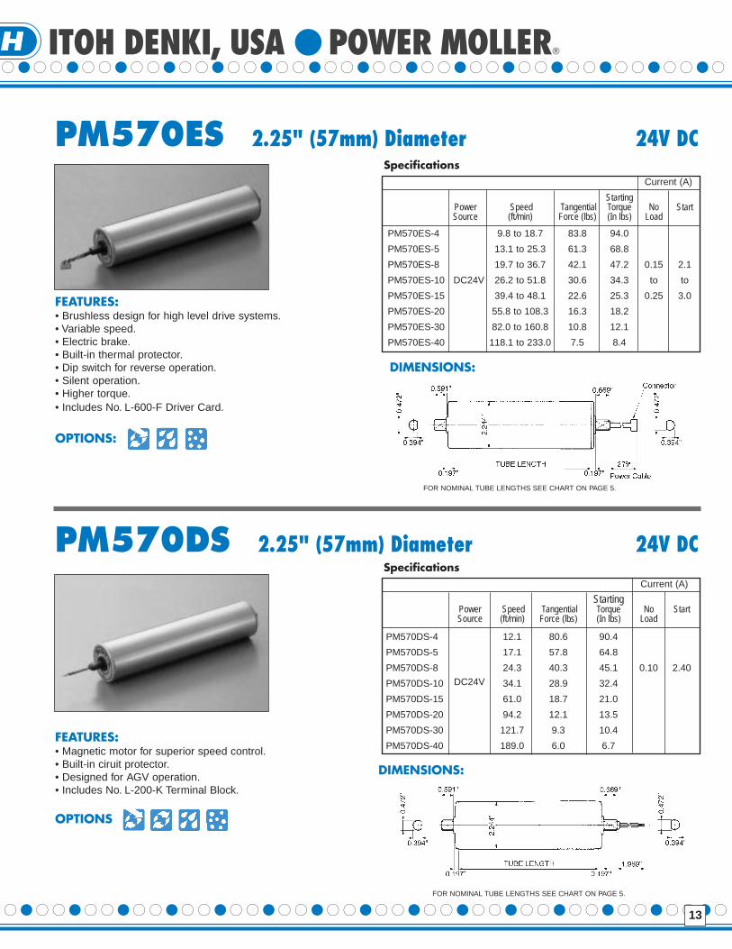
FEATURES:• Brushless design for high level drive systems.• Variable speed.• Electric brake.• Built-in thermal protector.• Dip switch for reverse operation.• Silent operation.• Higher torque.• Includes No. L-600-F Driver Card.
OPTIONS:
PM570ES 2.25" (57mm) Diameter 24V DC
FEATURES:• Magnetic motor for superior speed control.• Built-in ciruit protector.• Designed for AGV operation.• Includes No. L-200-K Terminal Block.
OPTIONS
PM570DS 2.25" (57mm) Diameter 24V DC
StartingPower Speed Tangential Torque No StartSource (ft/min) Force (lbs) (In lbs) Load
PM570ES-4 9.8 to 18.7 83.8 94.0
PM570ES-5 13.1 to 25.3 61.3 68.8
PM570ES-8 19.7 to 36.7 42.1 47.2 0.15 2.1
PM570ES-10 DC24V 26.2 to 51.8 30.6 34.3 to to
PM570ES-15 39.4 to 48.1 22.6 25.3 0.25 3.0
PM570ES-20 55.8 to 108.3 16.3 18.2
PM570ES-30 82.0 to 160.8 10.8 12.1
PM570ES-40 118.1 to 233.0 7.5 8.4
SpecificationsCurrent (A)
StartingPower Speed Tangential Torque No StartSource (ft/min) Force (lbs) (In lbs) Load
PM570DS-4 12.1 80.6 90.4
PM570DS-5 17.1 57.8 64.8
PM570DS-8 24.3 40.3 45.1 0.10 2.40
PM570DS-10 34.1 28.9 32.4
PM570DS-15 61.0 18.7 21.0
PM570DS-20 94.2 12.1 13.5
PM570DS-30 121.7 9.3 10.4
PM570DS-40 189.0 6.0 6.7
Specifications
DC24V
Current (A)
DIMENSIONS:
DIMENSIONS:
FOR NOMINAL TUBE LENGTHS SEE CHART ON PAGE 5.
FOR NOMINAL TUBE LENGTHS SEE CHART ON PAGE 5.

14
PM605ES 2.38" (60.5mm) Diameter 24V DC
FEATURES:• Designed for heavy load transfer. • Built-in thermal protector.• Brushless design for high level • Dip switch for reverse
drive systems. operation.• Variable speed. • Silent operation.• Electric brake. • Higher torque.• Includes No. L-600-F Driver Card.
OPTIONS:
PM605DS 2.38" (60.5mm) Diameter 24V DC
FEATURES:• Designed for heavy load transfer.• Magnetic motor for superior speed control.• Built-in circuit breaker.• Designed for AGV operation.• Includes No. L-200-K Terminal Block.
OPTIONS:
Power Speed Tangential Starting No StartSource (ft/min) Force (lbs) Torque (lbs) Load
PM605ES-4 9.8 to 19.7 79.0 94.0
PM605ES-5 13.5 to 26.9 57.8 68.8
PM605ES-8 19.7 to 39.4 39.6 47.2 0.15 2.1
PM605ES-10 26.9 to 53.2 28.9 34.3 to to
PM605ES-15 41.3 to 83.0 21.3 25.3 0.25 3.0
PM605ES-20 57.7 to 115.2 15.3 18.2
PM605ES-30 86.3 to 172.9 10.2 12.1
PM605ES-40 124.7 to 249.4 7.1 8.4
Specifications
DC24V
Current (A)
Power Speed Tangential Starting No StartSource (ft/min) Force (lbs) Torque (lbs) Load
PM605DS-4 12.8 75.9 90.4
PM605DS-5 18.0 54.5 64.8
PM605DS-8 25.6 37.9 45.1
PM605DS-10 36.1 27.2 32.4 0.10 2.40
PM605DS-15 64.6 17.6 21.0
PM605DS-20 99.7 11.4 13.5
PM605DS-30 128.9 8.8 10.4
PM605DS-40 200.5 5.6 6.7
Specifications
DC24V
Current (A)
DIMENSIONS:
DIMENSIONS:
FOR NOMINAL TUBE LENGTHS SEE CHART ON PAGE 5.
FOR NOMINAL TUBE LENGTHS SEE CHART ON PAGE 5.
ITOH DENKI, USA POWER MOLLER
15
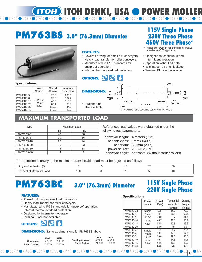
FEATURES:• Powerful driving for small belt conveyors. • Designed for continuous and
Heavy load transfer for roller conveyors. intermittent operation.• Manufactured to IP55 standards for • Operation without oil bath.
dustproof operation. • Eliminates risk of oil leakage.• Internal thermal overload protection. • Terminal Block not available.
OPTIONS:
DIMENSIONS:
• Straight tubealso available.
MAXIMUM TRANSPORTED LOADReferenced load values were obtained under the following test parameters:
conveyor length: 4 meters (13ft).belt thickness: 1mm (.040in).
belt width: 500mm (20in).power source: 200VAC/3-PH.
conveyor angle: horizontal (Without carrier rollers)
Type Maximum Load
kg lb.PM763BS-5 40 88PM763BS-8 30 66PM763BS-10 20 44PM763BS-20 15 33PM763BS-30 8 18PM763BS-40 4 9
For an inclined conveyor, the maximum transferrable load must be adjusted as follows:
Angle of Inclination (*) 0 5 10 20 30
Percent of Maximum Load 100 85 70 55 40
SpecificationsPower Speed TangentialSource (ft/min) force (lbs)
PM763BS-5 20.0 233.5PM763BS-8 27.2 167.2PM763BS-10 40.0 110.9PM763BS-20 82.4 60.3PM763BS-30 110.6 44.9PM763BS-40 170.0 29.3
3 Phase230V90W
FEATURES:• Powerful driving for small belt conveyors.• Heavy load transfer for roller conveyors.• Manufactured to IP55 standards for dustproof operation.• Internal thermal overload protection.• Designed for intermittent operation.• Terminal Block not available.
OPTIONS:
DIMENSIONS: Same as dimensions for PM763BS above.
115V 220VCondenser: 4.5 µF 1.2 µF
Rated Current: 0.37 A 0.17 A
115V Single PhasePM763BS 3.0" (76.3mm) Diameter 230V Three Phase
460V Three Phase*
PM763BC 3.0" (76.3mm) Diameter 115V Single Phase220V Single Phase
Power Speed Tangential StartingSource (ft/min) force (lbs) Torque
Nominal (In lbs)PM763BC-2.5 9.8 66.0 70.0PM763BC-4 13.1 50.8 52.2PM763BC-5 20.0 33.7 34.7PM763BC-10 40.7 16.5 16.8PM763BC-15 54.5 12.3 12.6PM763BC-20 84.0 7.9 8.3PM763BC-2.5 9.8 58.7 70.7PM763BC-4 13.1 44.0 52.8PM763BC-5 20.0 29.0 35.0PM763BC-10 40.7 14.3 17.1PM763BC-15 54.5 10.6 12.6PM763BC-20 84.0 6.8 8.3
SinglePhase115VInput42W
SinglePhase220VInput38W
115V 220VStar ting Current: 0.74 A 0.32 A
Rated Output: 21.9 W 19.0 W
Specifications
FOR NOMINAL TUBE LENGTHS SEE CHART ON PAGE 5
* Please check with an Itoh Denki representative to review 460/3/60 applications.

135 Stewart Road • Hanover Industrial EstatesWilkes-Barre, Pennsylvania 18706-1462
Telephone: 570-820-8811Facsimile: 570-820-8838
www.itohdenki.comE-mail: [email protected]
Revised 3/01
ITOH DENKI U.S.A., INC.

ITOH DENKI - TECHNOLOGY FOR TOMORROW