Embed Size (px)
Citation preview
®
Job Name:
Job Number:
Model Numbers:
PageSPecification Submittal
Light Management Hub
the Quantum® light management hub provides a centralized connection point for lutron® QS devices, including energi Savr nodetm, GRafiK eye® QS, Sivoia® QS shades, and lutron® dimming and switching panels.
Features• Designed to control, manage, and monitor digital
addressable ballasts, lutron® power panels, GRafiK eye® QS, energi Savr nodetm QS, and Sivoia® QS shade systems in a building or whole campus.
• Supports both astronomic and time-of-day events to automatically control the lights and shades in the system.
• Simple reconfiguration of a space without rewiring.• Individually control, monitor, and adjust any light or
shade in a space.• QS control links are topology-free.
Panel Capabilities• Lighting management panels communicate via an
ethernet connection using multicast protocol.• Each hub supports up to 2 Quantum® processors with
total of 3 links each that can be individually configured to comunicate with:
- Lutron® power panels - Lutron® QS devices
369-377b 1 06.14.12
Centralized Control EquipmentQuantum® 230 V CE Light Management Hub
®
Job Name:
Job Number:
Model Numbers:
PageSPecification Submittal
369-377b 2 06.14.12
Centralized Control Equipment230 V CE Light Management HubQuantum®
Specifications
Regulatory Approvals• ce
Power• Input voltage: 220 - 240 V , normal/emergency feed
50 / 60 Hz 10 A• Output: Processor - 24 V 1 A per link 83 btus/hr
Physical Design• Enclosure: IP-20 protection• Weight: 20.4 kg
Mounting• Surface mount only
Environment• For indoor use only• 0 ºC to 40 ºC• Relative humidity less than 90% non-condensing
®
Job Name:
Job Number:
Model Numbers:
PageSPecification Submittal
369-377b 3 06.14.12
Centralized Control Equipment230 V CE Light Management HubQuantum®
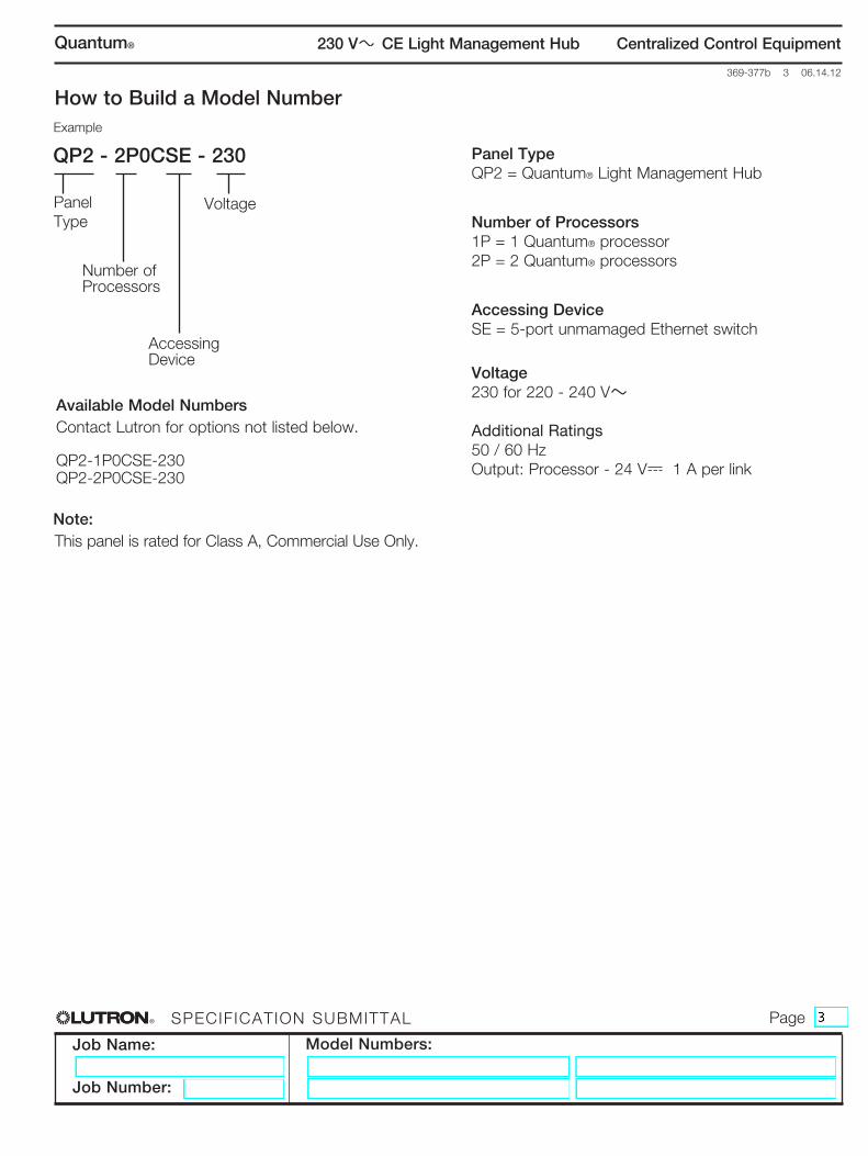
How to Build a Model Number example
QP2 - 2P0CSE - 230
Panel type
number of Processors
accessing Device
Voltage
Panel TypeQP2 = Quantum® Light Management Hub
Number of Processors1P = 1 Quantum® processor2P = 2 Quantum® processors
Accessing DeviceSE = 5-port unmamaged Ethernet switch
Voltage230 for 220 - 240 V
Additional Ratings50 / 60 HzOutput: Processor - 24 V 1 A per link
Available Model Numberscontact lutron for options not listed below.
QP2-1P0CSE-230QP2-2P0CSE-230
Note: this panel is rated for class a, commercial use only.
®
Job Name:
Job Number:
Model Numbers:
PageSPecification Submittal
369-377b 4 06.14.12
Centralized Control Equipment230 V CE Light Management HubQuantum®
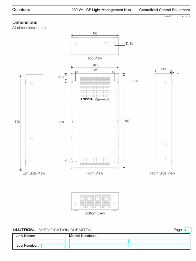
Dimensionsall dimensions in mm
400
400
324
63.5
673800 800
1484
Front ViewLeft Side View Right Side View
Top View
Bottom View
R R
®
22.22
7.95
®
Job Name:
Job Number:
Model Numbers:
PageSPecification Submittal
369-377b 5 06.14.12
Centralized Control Equipment230 V CE Light Management HubQuantum®
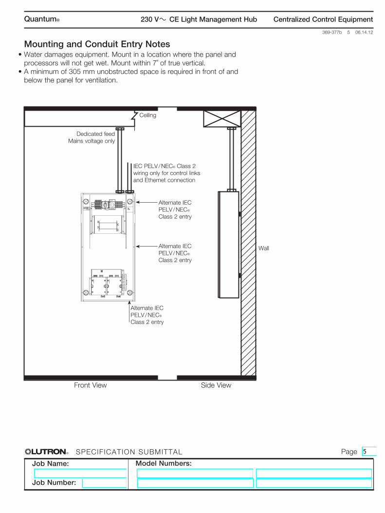
Mounting and Conduit Entry Notes• Water damages equipment. Mount in a location where the panel and
processors will not get wet. Mount within 7˚ of true vertical.• A minimum of 305 mm unobstructed space is required in front of and
below the panel for ventilation.
Front View Side View
ceiling
Wall
IEC PELV / NEC® Class 2 wiring only for control links and ethernet connection
Dedicated feedmains voltage only
alternate iec PELV / NEC® Class 2 entry
alternate iec PELV / NEC® Class 2 entry
alternate iec PELV / NEC® Class 2 entry
®
Job Name:
Job Number:
Model Numbers:
PageSPecification Submittal
369-377b 6 06.14.12
Centralized Control Equipment230 V CE Light Management HubQuantum®
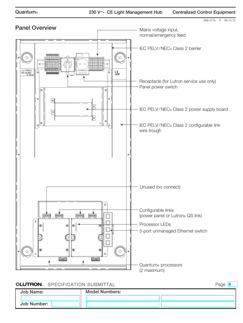
Panel Overview mains voltage input, normal/emergency feed
Receptacle (for lutron service use only)Panel power switch
IEC PELV / NEC® Class 2 power supply board
Configurable links(power panel or lutron® QS link)
5-port unmanaged Ethernet switch
Quantum® processors (2 maximum)
IEC PELV / NEC® Class 2 configurable link wire trough
Processor LEDs
unused (no connect)
IEC PELV / NEC® Class 2 barrier
®
Job Name:
Job Number:
Model Numbers:
PageSPecification Submittal
369-377b 7 06.14.12
Centralized Control Equipment230 V CE Light Management HubQuantum®
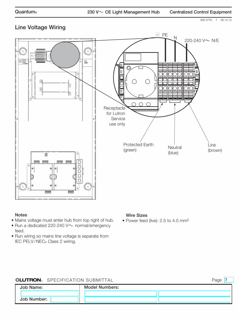
Line Voltage Wiring
Protected earth(green) neutral
(blue)
line(brown)
Notes• Mains voltage must enter hub from top right of hub.• Run a dedicated 220-240 V normal/emergency
feed.• Run wiring so mains line voltage is separate from
IEC PELV / NEC® Class 2 wiring.
Pen
220-240 V n/e
Wire Sizes• Power feed (live): 2.5 to 4.0 mm2
Receptacle for lutron
Service use only
®
Job Name:
Job Number:
Model Numbers:
PageSPecification Submittal
369-377b 8 06.14.12
Centralized Control Equipment230 V CE Light Management HubQuantum®
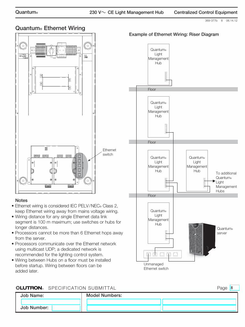
Quantum® Ethernet Wiring
Notes• Ethernet wiring is considered IEC PELV / NEC® Class 2,
keep Ethernet wiring away from mains voltage wiring.• Wiring distance for any single Ethernet data link
segment is 100 m maximum; use switches or hubs for longer distances.
• Processors cannot be more than 6 Ethernet hops away from the server.
• Processors communicate over the Ethernet network using multicast UDP; a dedicated network is recommended for the lighting control system.
• Wiring between Hubs on a floor must be installed before startup. Wiring between floors can be added later.
ethernet switch
Example of Ethernet Wiring: Riser Diagram
Quantum® light
management Hub
Quantum® light
management Hub
Quantum® light
management Hub
Quantum® light
management Hub
Quantum® light
management Hub
Quantum® server
unmanaged ethernet switch
floor
floor
floor
to additional Quantum® light management Hubs
®
Job Name:
Job Number:
Model Numbers:
PageSPecification Submittal
369-377b 9 06.14.12
Centralized Control Equipment230 V CE Light Management HubQuantum®
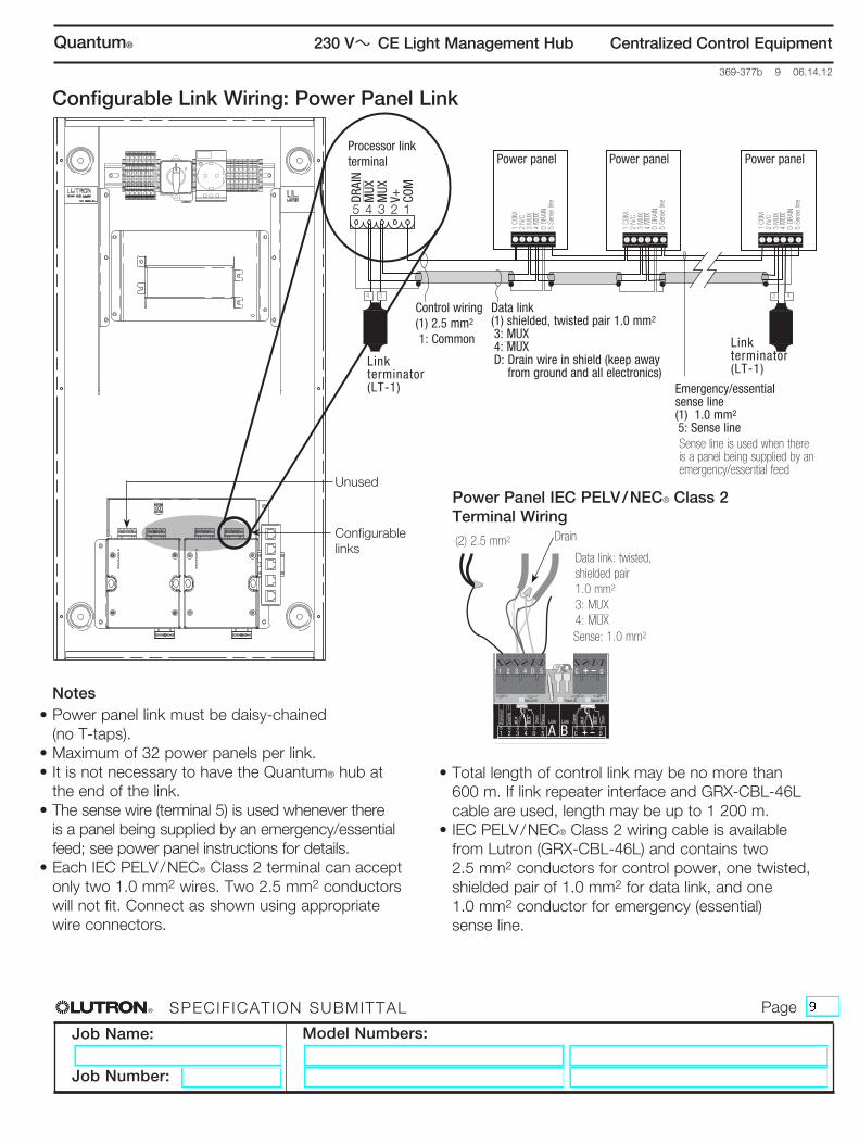
Configurable Link Wiring: Power Panel Link
5 4 3 2 1
DRAI
NM
UXM
UXV+ CO
M
Link terminator (LT-1)
Control wiring(1) 2.5 mm2 1: Common
Data link(1) shielded, twisted pair 1.0 mm2
3: MUX4: MUXD: Drain wire in shield (keep away
from ground and all electronics)
Power panel
1 CO
M2
N/C
3 M
UX4
MUX
D DR
AIN
5 Se
nse
line
Power panel
1 CO
M2
N/C
3 M
UX4
MUX
D DR
AIN
5 Se
nse
line
Power panel
1 CO
M2
N/C
3 M
UX4
MUX
D DR
AIN
5 Se
nse
line
4 3 3 4
Link terminator (LT-1)
Emergency/essential sense line(1) 1.0 mm2
5: Sense lineSense line is used when there is a panel being supplied by an emergency/essential feed
Data A OK Data B OKPower OK
1 2 3 4 5D C D
A B
Com
mon
24VF
W
MUX
MUX
Drai
nSe
nse
Com
m
Drai
n
MUX
MUX
C1 2 3 4 D 5 D
Link Link
SELECT C IRCUIT
Data link: twisted,shielded pair1.0 mm2
3: MUX4: MUX
Drain(2) 2.5 mm2 configurable links
Notes• Power panel link must be daisy-chained
(no T-taps).• Maximum of 32 power panels per link.• It is not necessary to have the Quantum® hub at
the end of the link.• The sense wire (terminal 5) is used whenever there
is a panel being supplied by an emergency/essential feed; see power panel instructions for details.
• Each IEC PELV / NEC® Class 2 terminal can accept only two 1.0 mm2 wires. Two 2.5 mm2 conductors will not fit. connect as shown using appropriate wire connectors.
Power Panel IEC PELV / NEC® Class 2 Terminal Wiring
• Total length of control link may be no more than 600 m. If link repeater interface and GRX-CBL-46L cable are used, length may be up to 1 200 m.
• IEC PELV / NEC® Class 2 wiring cable is available from Lutron (GRX-CBL-46L) and contains two 2.5 mm2 conductors for control power, one twisted, shielded pair of 1.0 mm2 for data link, and one 1.0 mm2 conductor for emergency (essential) sense line.
Sense: 1.0 mm2
Processor link terminal
unused
®
Job Name:
Job Number:
Model Numbers:
PageSPecification Submittal
369-377b 10 06.14.12
Centralized Control Equipment230 V CE Light Management HubQuantum®
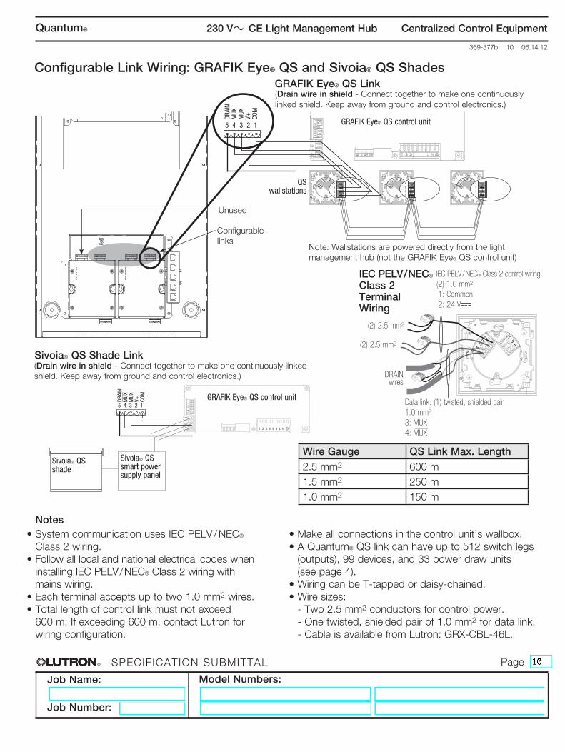
Configurable Link Wiring: GRAFIK Eye® QS and Sivoia® QS ShadesGRAFIK Eye® QS Link
4 3
2 1 C B A
4 3
2 1 C B A
4 3
2 1 C B A
5 4 3 2 1
4
3
2
1
4
3
2
1
4
3
2
1
GRAFIK Eye® QS control unit
QS wallstations
configurable links
12
34
12
AB
C
1 2 3 4 5 6 L N
5 4 3 2 1
Sivoia® QS smart power supply panel
Sivoia® QS shade
GRAFIK Eye® QS control unit
Sivoia® QS Shade Link
4 3 2
1 C B A
Data link: (1) twisted, shielded pair1.0 mm2
3: MUX4: MUX
IEC PELV / NEC® Class 2 control wiring(2) 1.0 mm2
1: Common2: 24 V
(2) 2.5 mm2
(2) 2.5 mm2
IEC PELV / NEC® Class 2 Terminal Wiring
Notes• System communication uses IEC PELV / NEC®
Class 2 wiring.• Follow all local and national electrical codes when
installing IEC PELV / NEC® Class 2 wiring with mains wiring.
• Each terminal accepts up to two 1.0 mm2 wires.• Total length of control link must not exceed
600 m; If exceeding 600 m, contact Lutron for wiring configuration.
• Make all connections in the control unit’s wallbox.• A Quantum® QS link can have up to 512 switch legs
(outputs), 99 devices, and 33 power draw units (see page 4).
• Wiring can be T-tapped or daisy-chained.• Wire sizes: - Two 2.5 mm2 conductors for control power. - One twisted, shielded pair of 1.0 mm2 for data link. - Cable is available from Lutron: GRX-CBL-46L.
Note: Wallstations are powered directly from the light management hub (not the GRafiK eye® QS control unit)
Wire Gauge QS Link Max. Length2.5 mm2 600 m1.5 mm2 250 m1.0 mm2 150 m
DRAI
NM
UXM
UXV+ CO
M
DRAI
NM
UXM
UXV+ CO
M
unused
(Drain wire in shield - Connect together to make one continuously linked shield. Keep away from ground and control electronics.)
(Drain wire in shield - Connect together to make one continuously linked shield. Keep away from ground and control electronics.) DRAIN
wires
®
Job Name:
Job Number:
Model Numbers:
PageSPecification Submittal
369-377b 11 06.14.12
Centralized Control Equipment230 V CE Light Management HubQuantum®
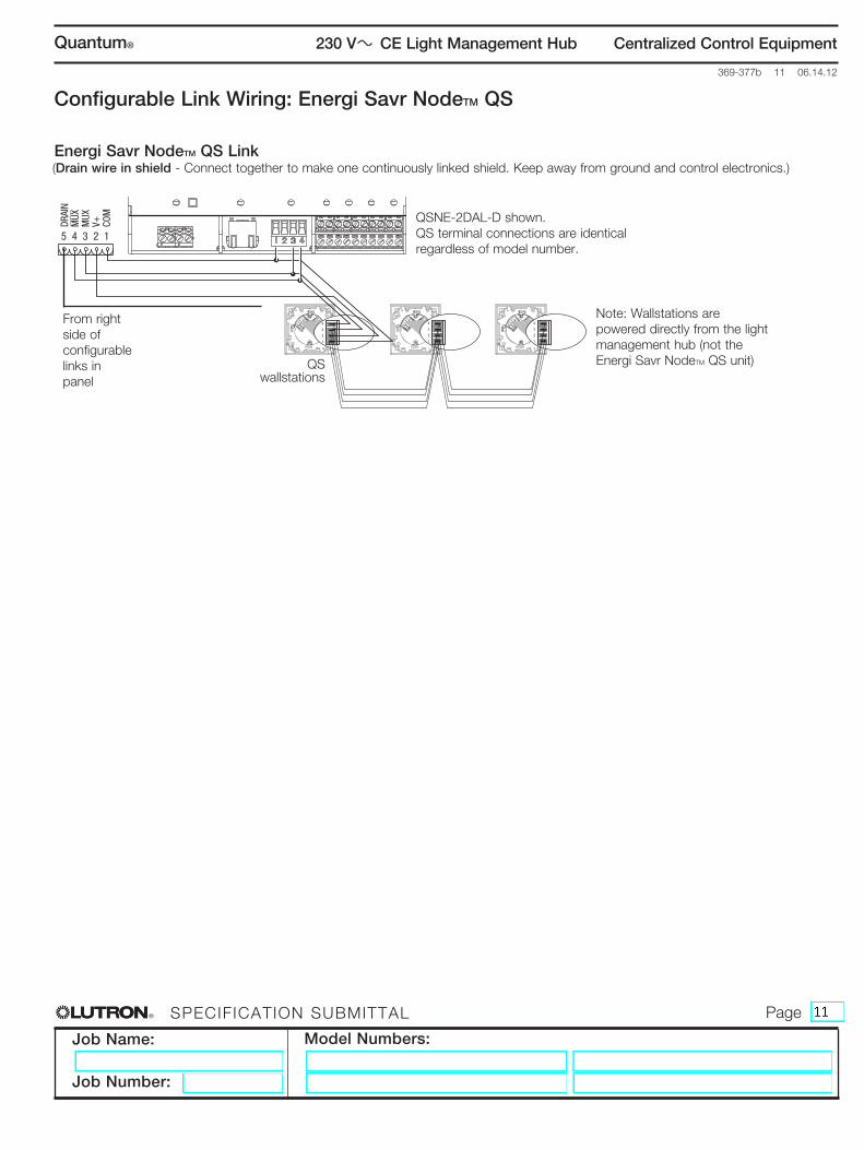
Configurable Link Wiring: Energi Savr NodeTM QS
4 3
2 1 C B A
4 3
2 1 C B A
4 3
2 1 C B A
5 4 3 2 1
4
3
2
1
4
3
2
1
4
3
2
1
QSNE-2DAL-D shown.QS terminal connections are identical regardless of model number.
from right side of configurable links in panel
QS wallstations
Note: Wallstations are powered directly from the light management hub (not the energi Savr nodetm QS unit)
Energi Savr NodeTM QS Link
DRAI
NM
UXM
UXV+ CO
M
(Drain wire in shield - Connect together to make one continuously linked shield. Keep away from ground and control electronics.)