Embed Size (px)
Citation preview
Laboratory of Nuclear Solid State Physics, USTC
VI

�
�
�
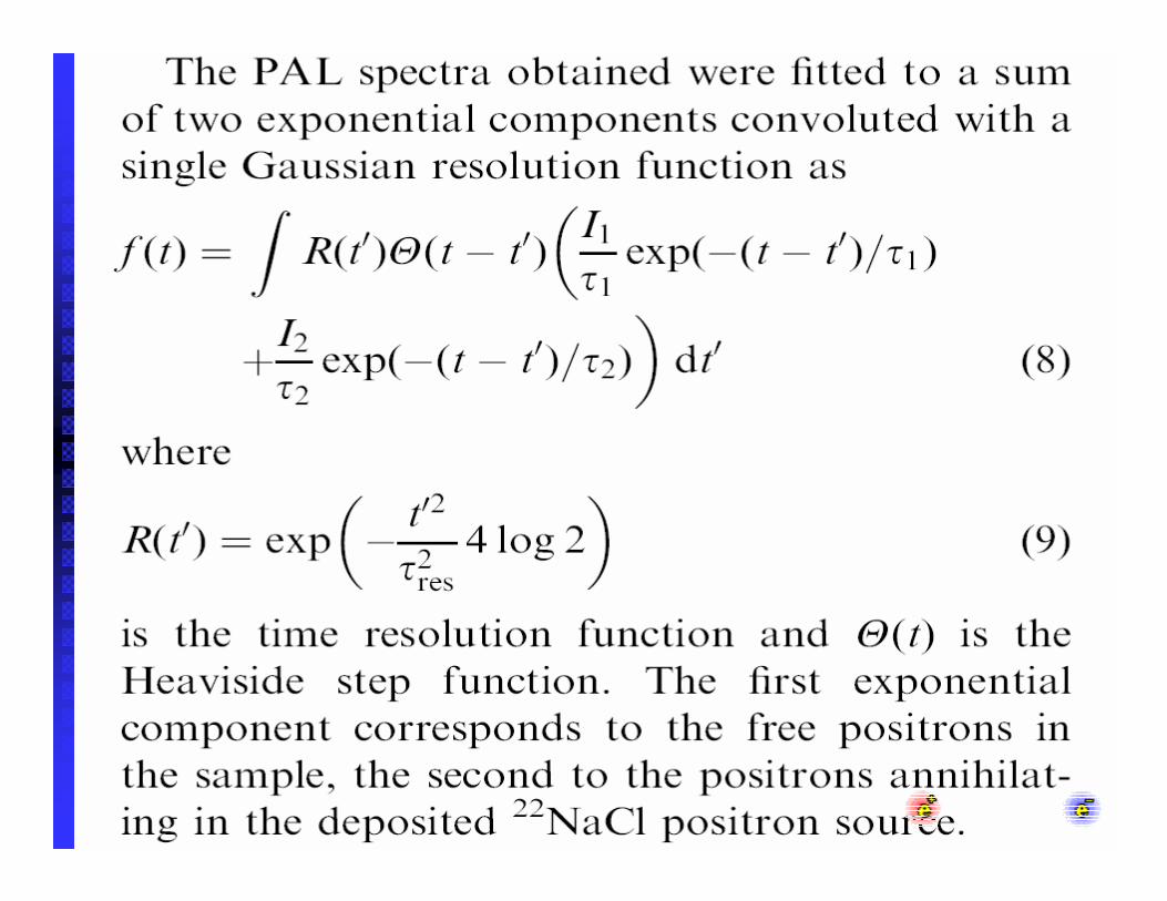
1.

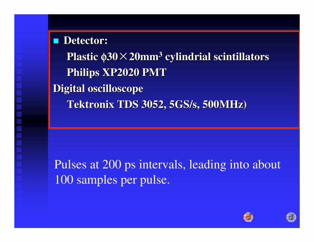
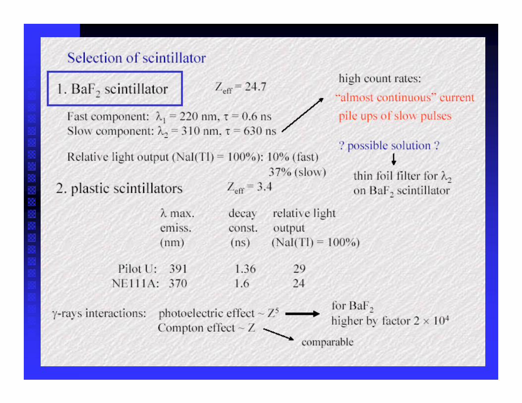
�� Detector: Detector: Plastic Plastic φφφφφφφφ3030 20mm20mm33 cylindrialcylindrial scintillatorsscintillatorsPhilips XP2020 PMTPhilips XP2020 PMT
Digital oscilloscopeDigital oscilloscopeTektronix TDS 3052, 5GS/s, 500MHz)Tektronix TDS 3052, 5GS/s, 500MHz)
Pulses at 200 ps intervals, leading into about 100 samples per pulse.
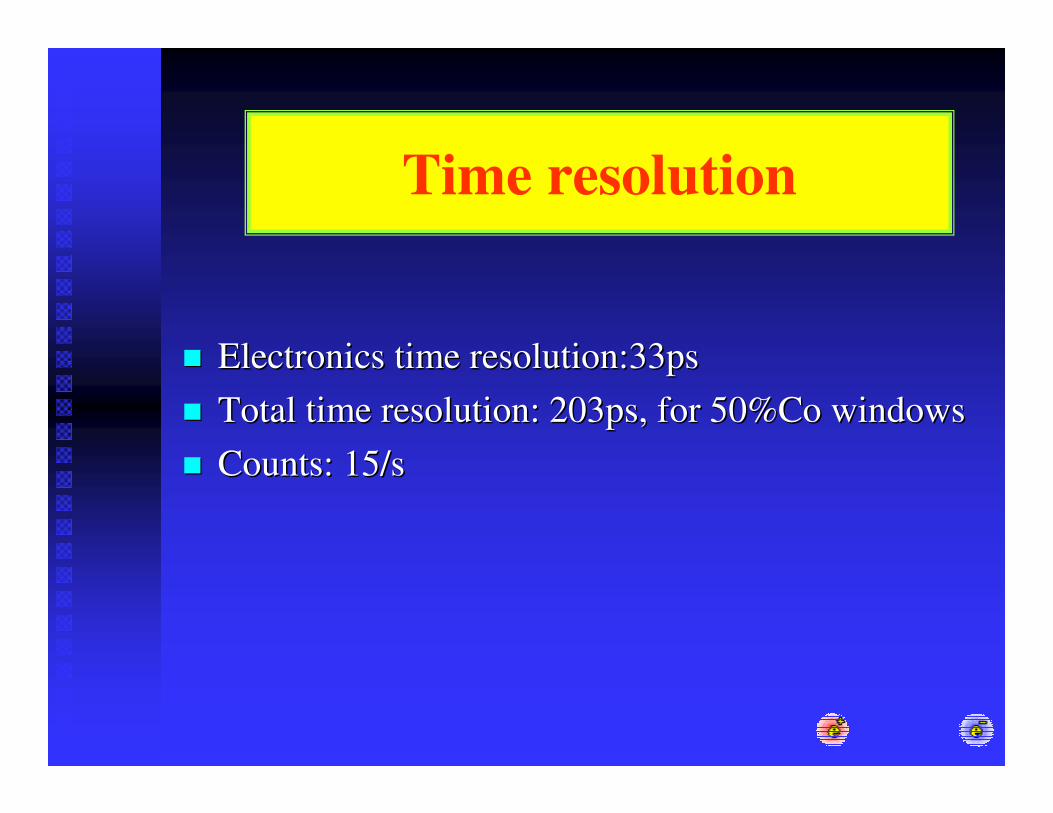
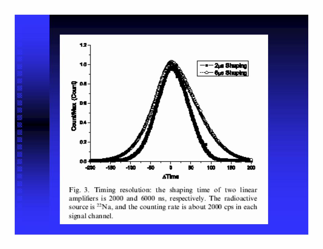
Time resolution
�� Electronics time resolution:33psElectronics time resolution:33ps�� Total time resolution: 203ps, for 50%Co windowsTotal time resolution: 203ps, for 50%Co windows�� Counts: 15/sCounts: 15/s
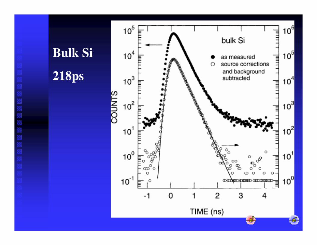
Bulk Si
218ps
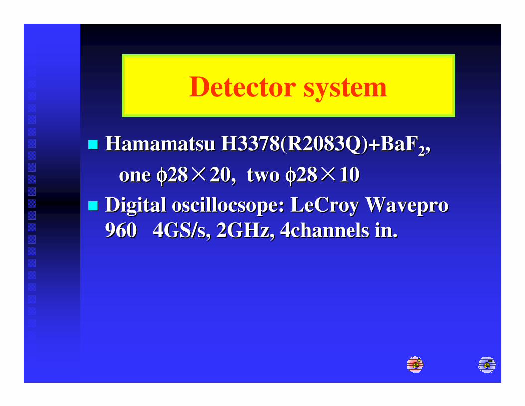
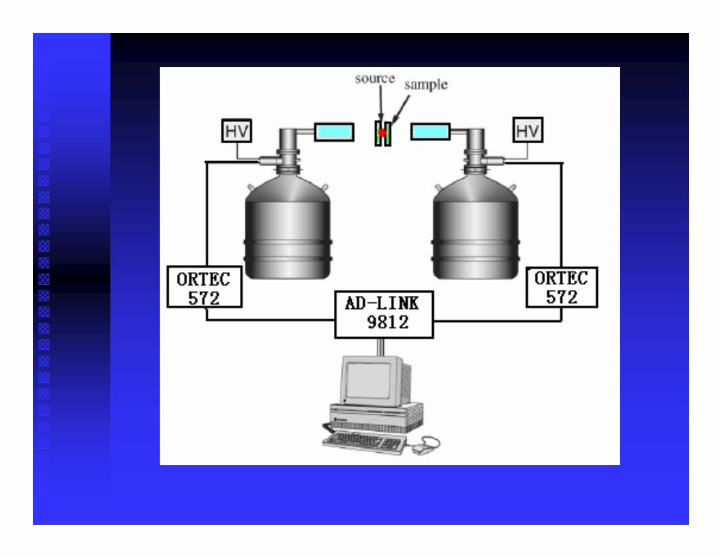
Detector system
�� HamamatsuHamamatsu H3378(R2083Q)+BaFH3378(R2083Q)+BaF22,,one one φφφφφφφφ2828 20, two 20, two φφφφφφφφ2828 1010
�� Digital Digital oscillocsopeoscillocsope: : LeCroyLeCroy WaveproWavepro960 4GS/s, 2GHz, 4channels in.960 4GS/s, 2GHz, 4channels in.
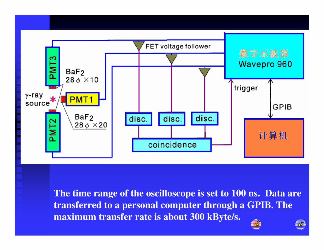
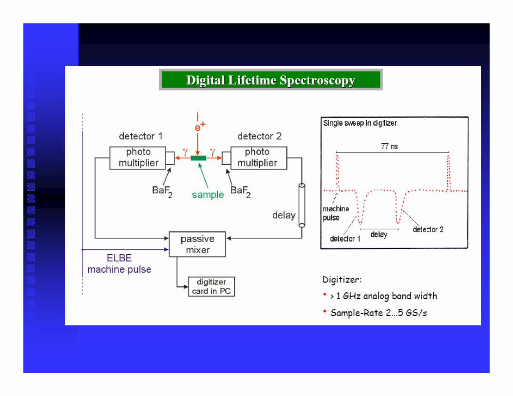
The time range of the oscilloscope is set to 100 ns. Data are transferred to a personal computer through a GPIB. The maximum transfer rate is about 300 kByte/s.
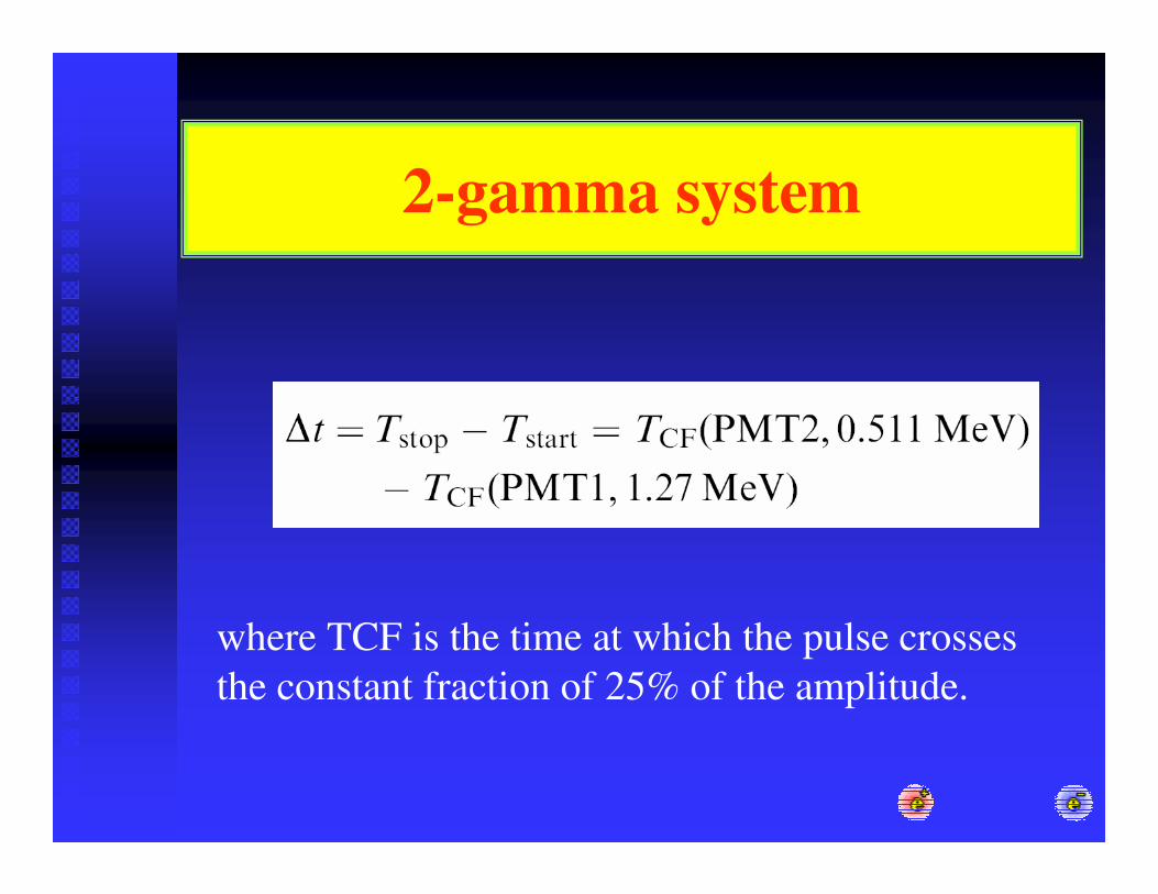
2-gamma system
where TCF is the time at which the pulse crosses the constant fraction of 25% of the amplitude.
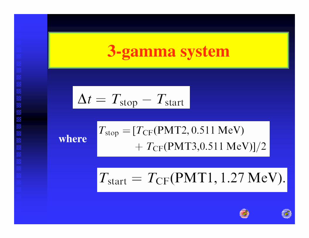
3-gamma system
where
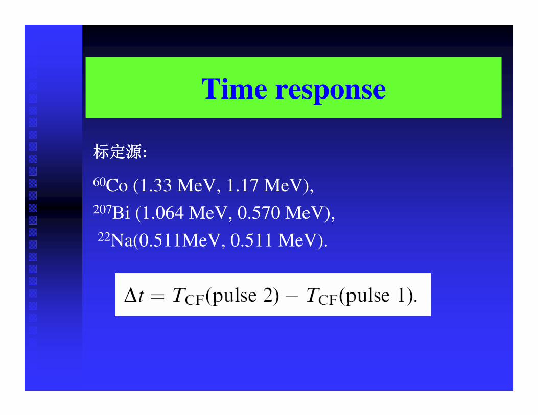
Time response
:
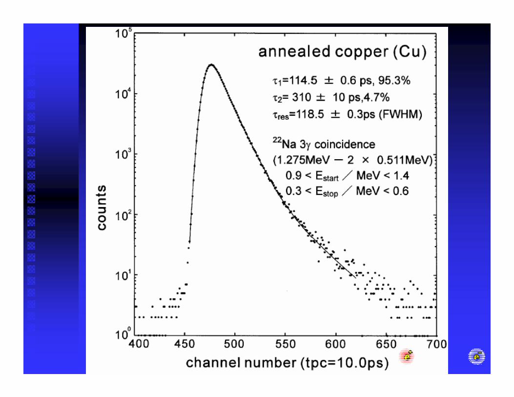
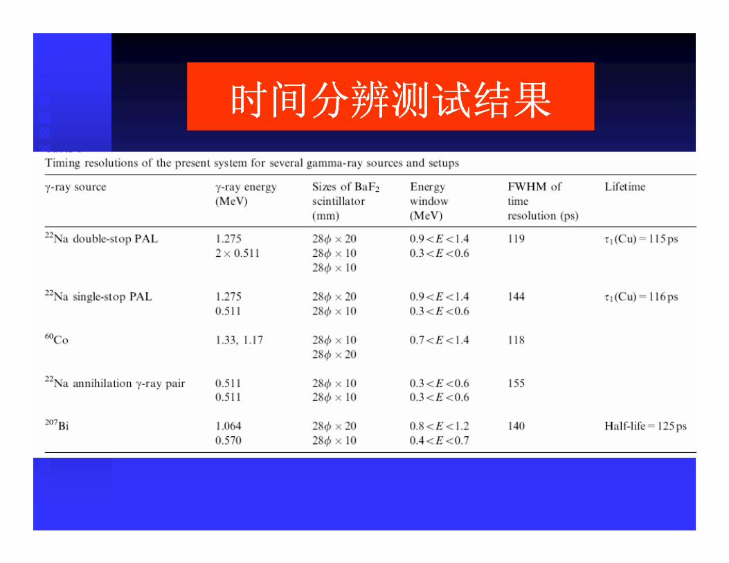
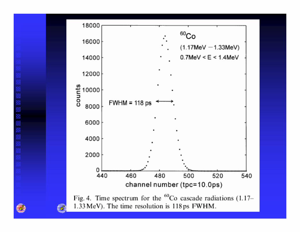
60Co (1.33 MeV, 1.17 MeV), 207Bi (1.064 MeV, 0.570 MeV),22Na(0.511MeV, 0.511 MeV).
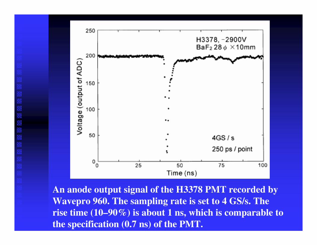
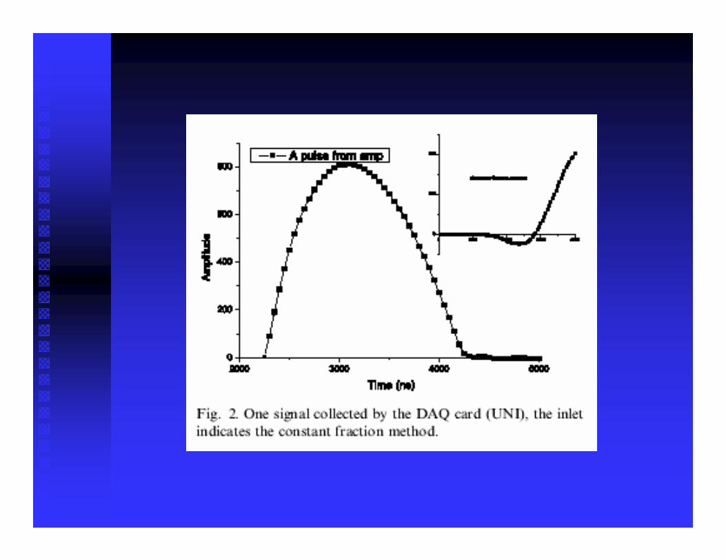
An anode output signal of the H3378 PMT recorded byWavepro 960. The sampling rate is set to 4 GS/s. The rise time (10–90%) is about 1 ns, which is comparable to the specification (0.7 ns) of the PMT.
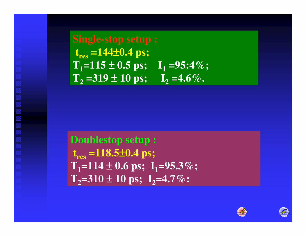
Single-stop setup :tres =144±±±±0.4 ps;T1=115 ±±±± 0.5 ps; I1 =95:4%; T2 =319 ±±±± 10 ps; I2 =4.6%.
Doublestop setup :tres =118.5±±±±0.4 ps;T1=114 ±±±± 0.6 ps; I1=95.3%;T2=310 ±±±± 10 ps; I2=4.7%:
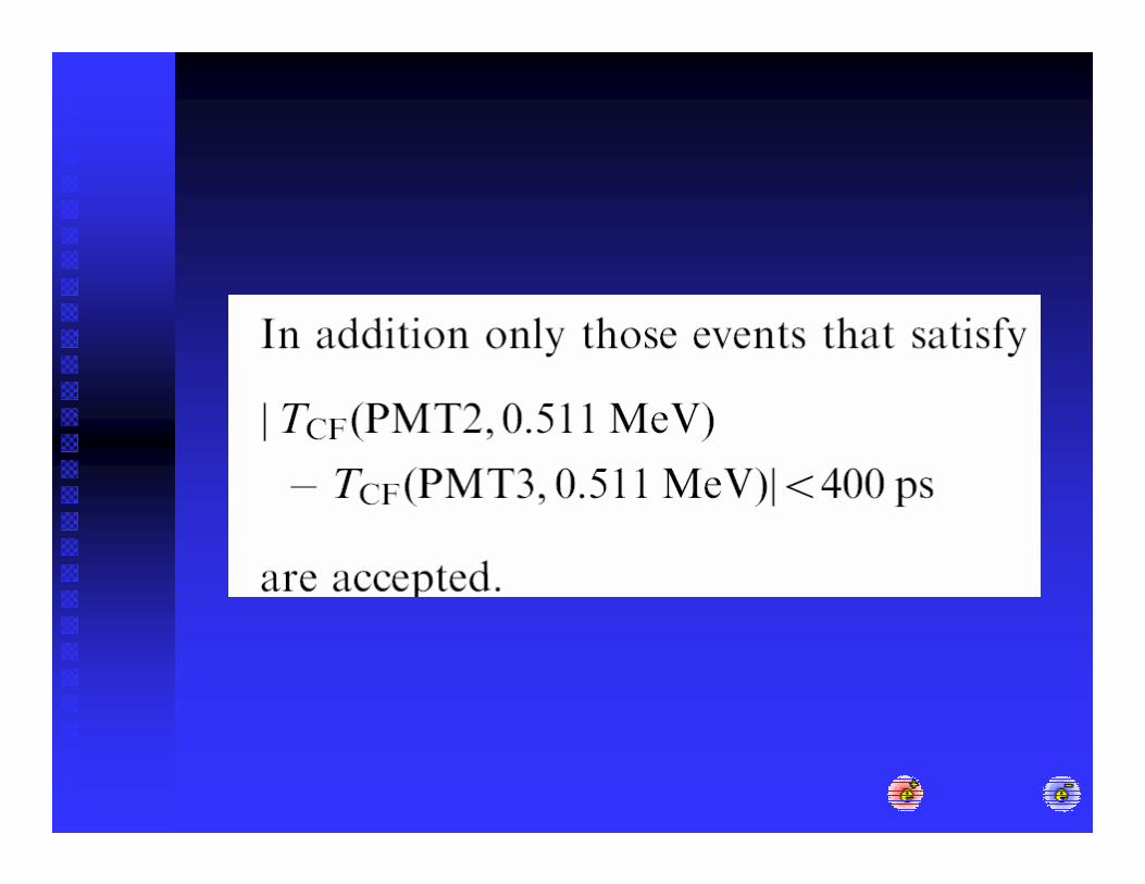
This improvement is explained as a result of the reduction in the fluctuations in the TCF(PMT2; 0.511 MeV) and TCF(PMT3; 0.511 MeV) by averaging. This amazingly high resolution is obtained easily by the double-stop setup at the expense of the reduction of the count rate to 1/5 of that of the single-stop setup. The count rate is still of practical use; it took B1day to accumulate one million counts with a source of~90 kBq (~2.4 mCi).
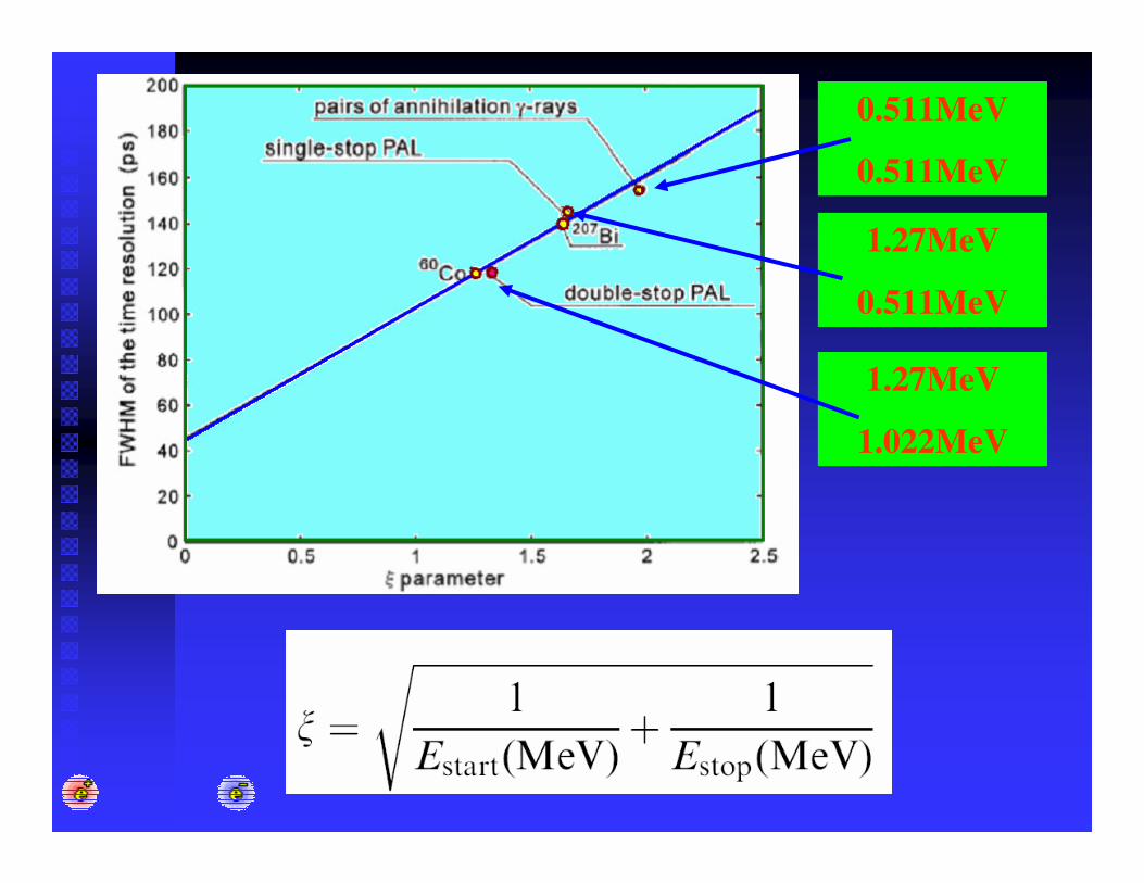
0.511MeV
0.511MeV
1.27MeV
0.511MeV
1.27MeV
1.022MeV
PAS
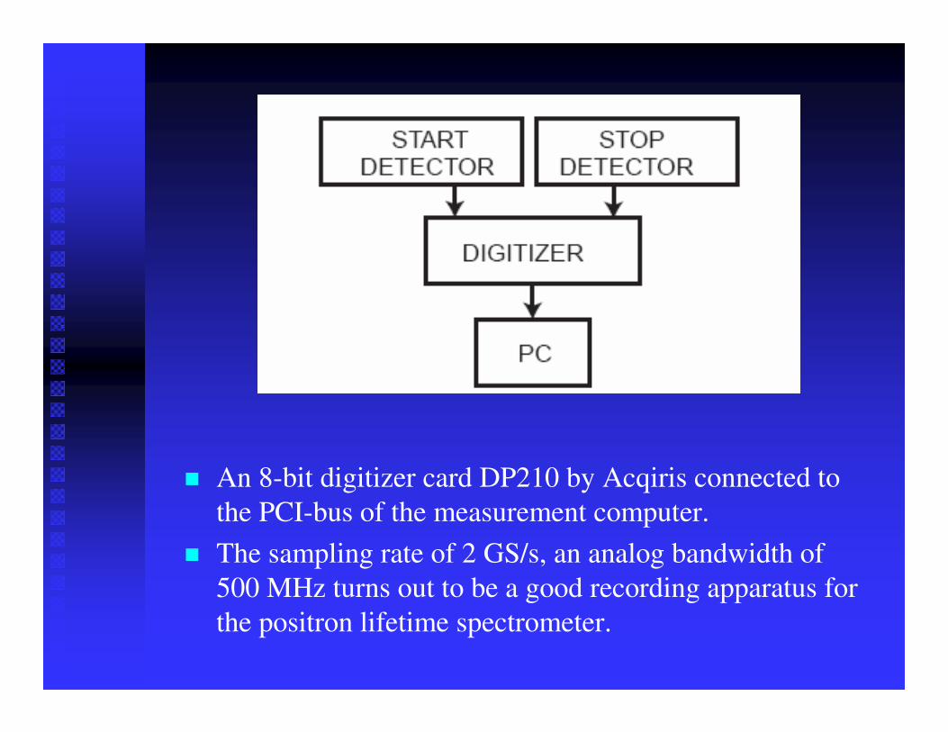
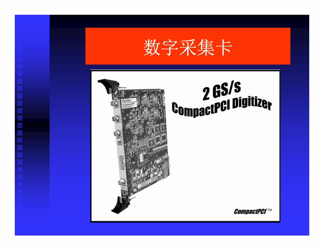
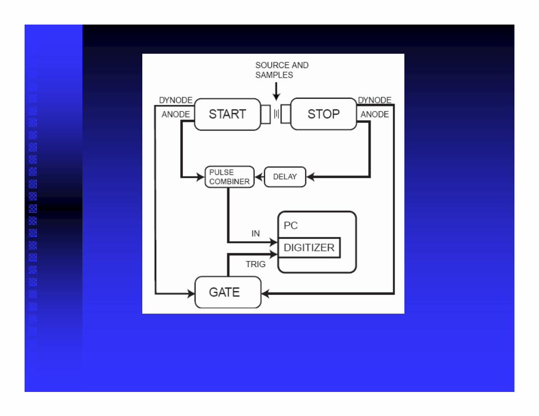
� An 8-bit digitizer card DP210 by Acqiris connected to the PCI-bus of the measurement computer.
� The sampling rate of 2 GS/s, an analog bandwidth of 500 MHz turns out to be a good recording apparatus for the positron lifetime spectrometer.
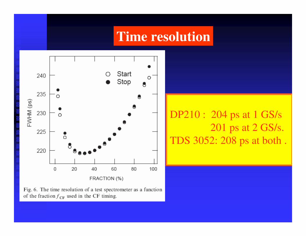
Time resolution
DP210 : 204 ps at 1 GS/s 201 ps at 2 GS/s.
TDS 3052: 208 ps at both .
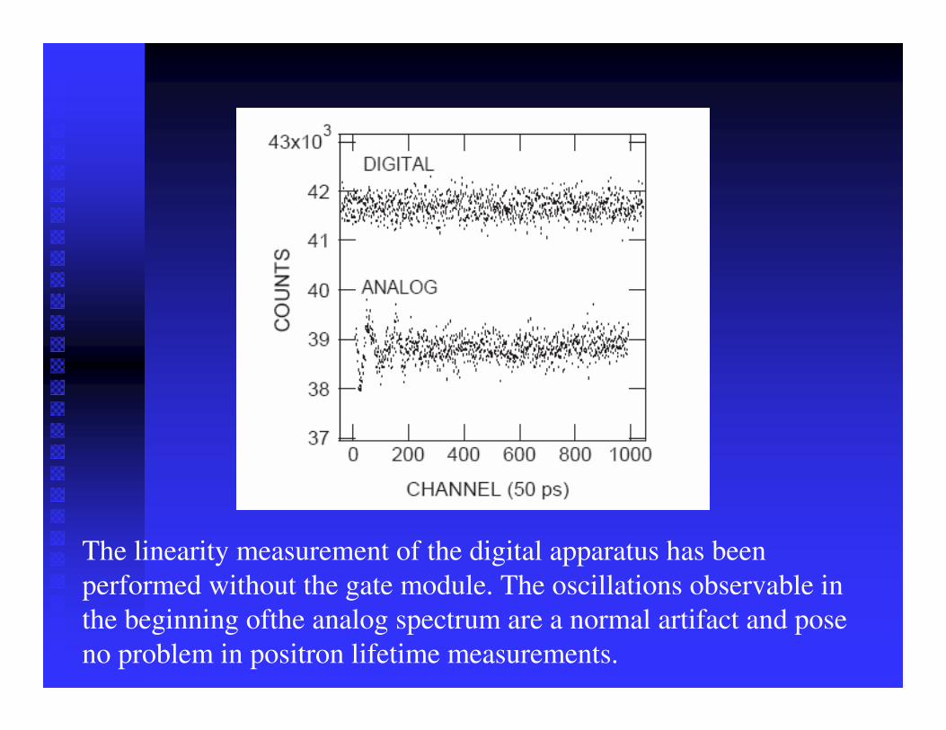
The linearity measurement of the digital apparatus has been performed without the gate module. The oscillations observable in the beginning ofthe analog spectrum are a normal artifact and pose no problem in positron lifetime measurements.
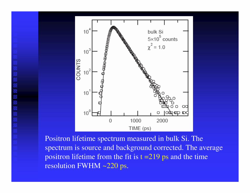
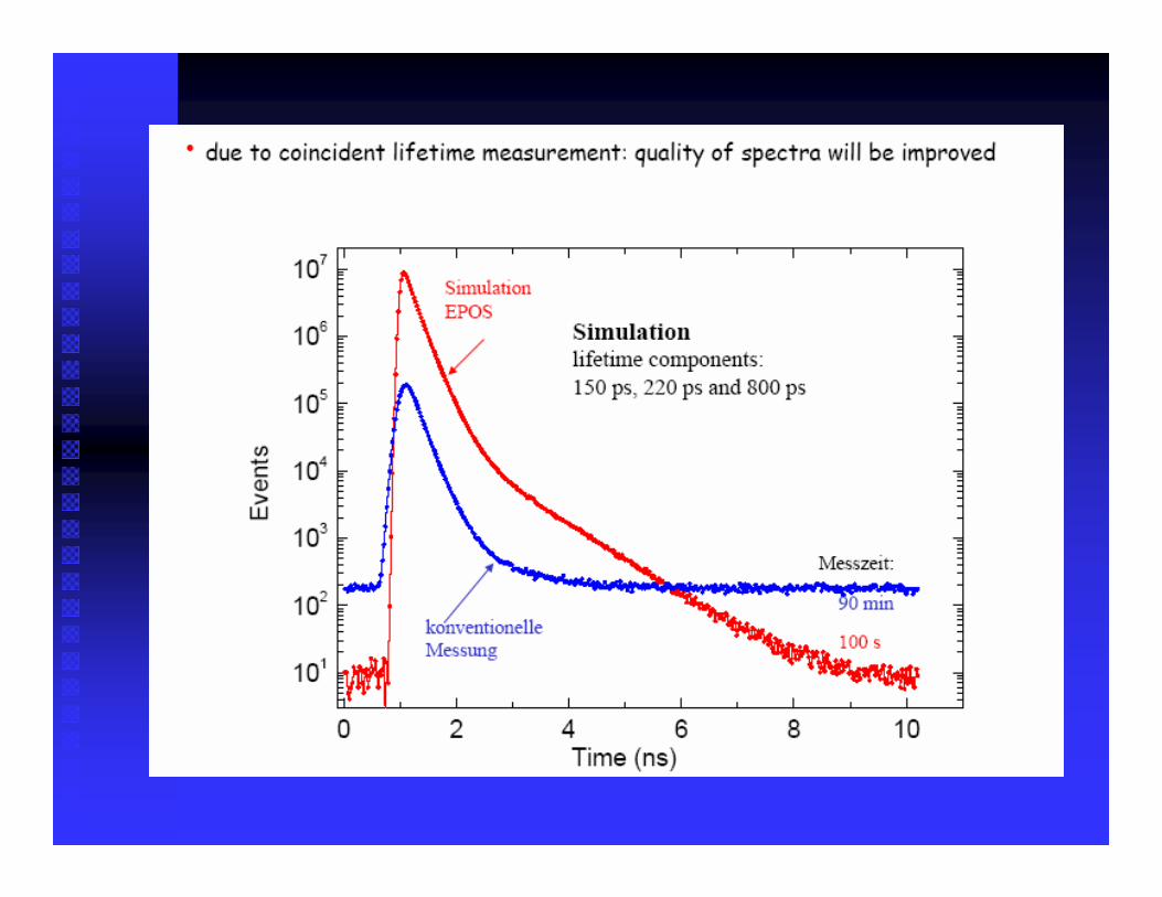
Positron lifetime spectrum measured in bulk Si. Thespectrum is source and background corrected. The averagepositron lifetime from the fit is t =219 ps and the timeresolution FWHM ~220 ps.
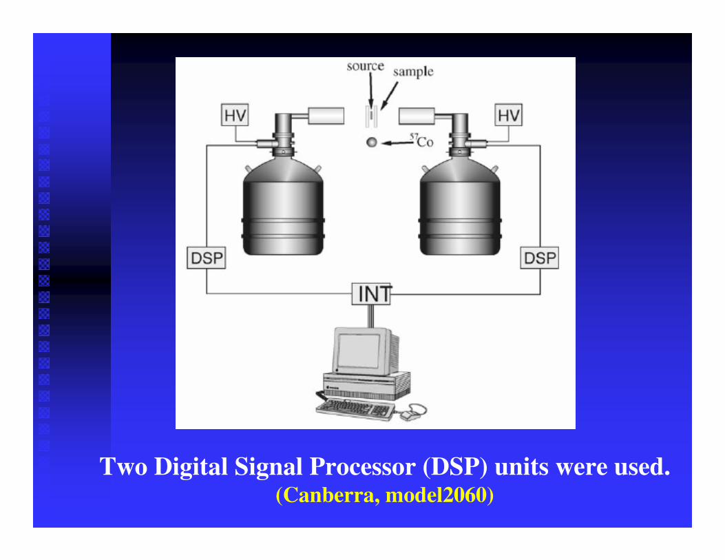
Two Digital Signal Processor (DSP) units were used.(Canberra, model2060)
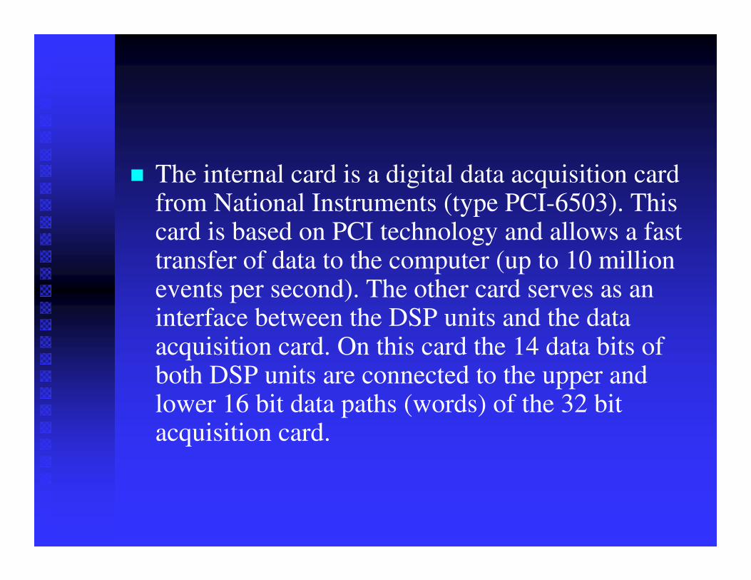
� The internal card is a digital data acquisition card from National Instruments (type PCI-6503). This card is based on PCI technology and allows a fast transfer of data to the computer (up to 10 million events per second). The other card serves as an interface between the DSP units and the data acquisition card. On this card the 14 data bits of both DSP units are connected to the upper and lower 16 bit data paths (words) of the 32 bit acquisition card.
� The analysis software was written using LabView(National Instruments).
� The coincidence count rate varies between 300 and 500 CPS, depending on the thickness of the sample
� The overall cost of this setup is estimated at about 60,000 euro which is on average about 10–15% lower than a setup with a conventional multi-parameter system.
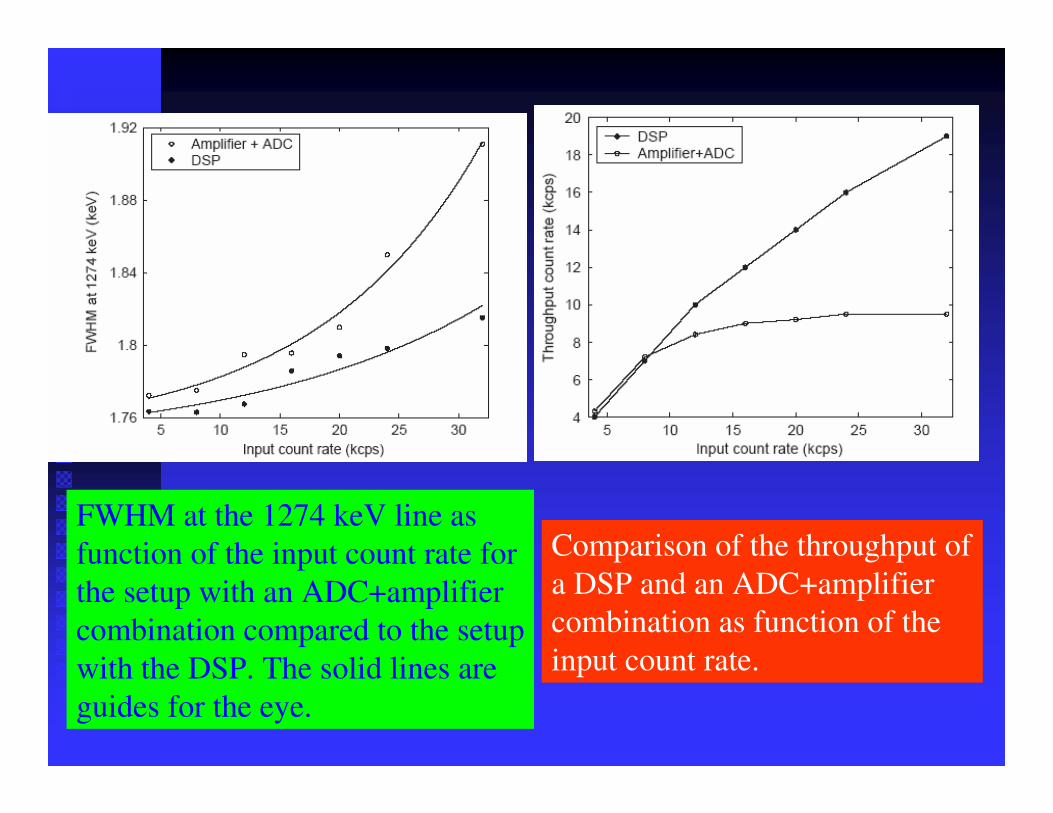
FWHM at the 1274 keV line as function of the input count rate for the setup with an ADC+amplifiercombination compared to the setup with the DSP. The solid lines are guides for the eye.
Comparison of the throughput of a DSP and an ADC+amplifiercombination as function of the input count rate.
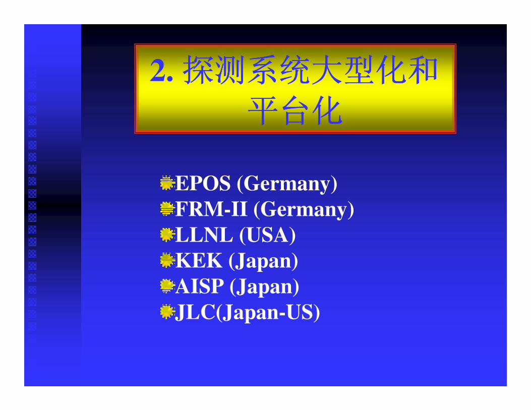
2.
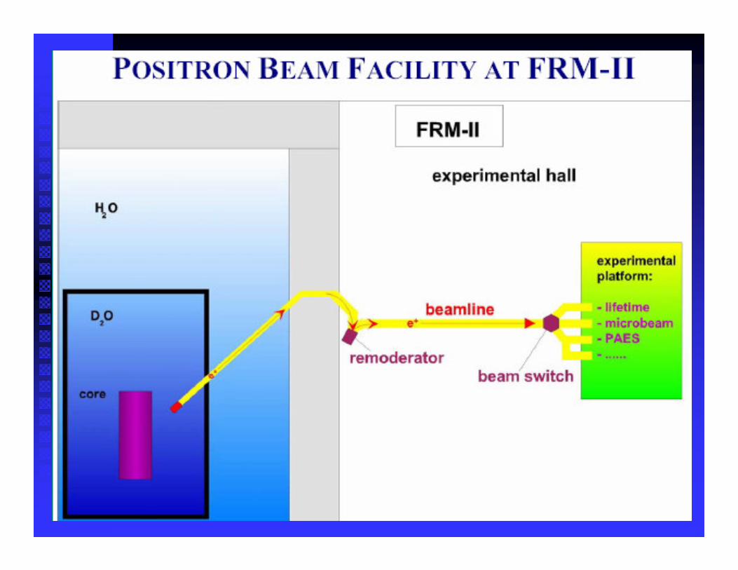
EPOS (Germany)FRM-II (Germany)LLNL (USA)KEK (Japan)AISP (Japan)JLC(Japan-US)
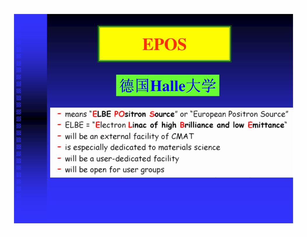
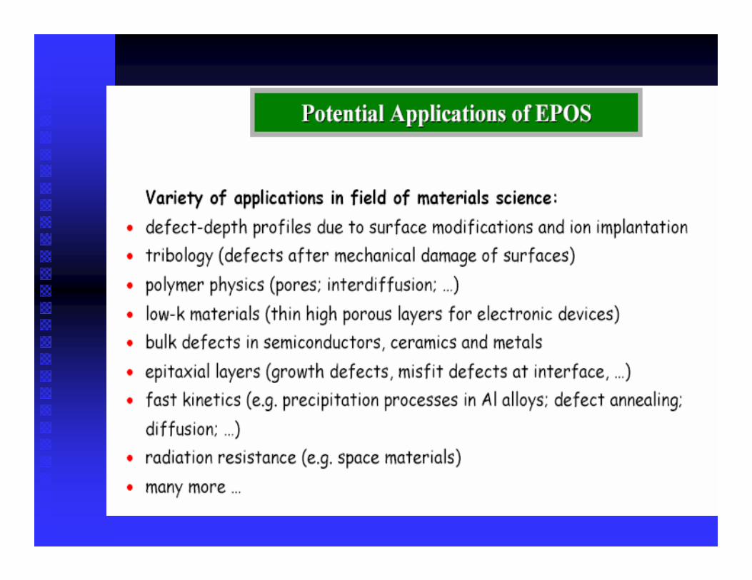
EPOS
Halle
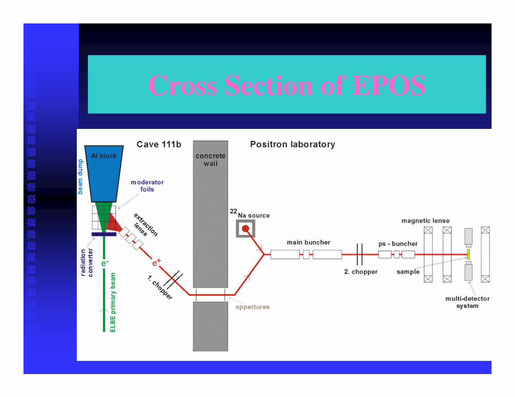
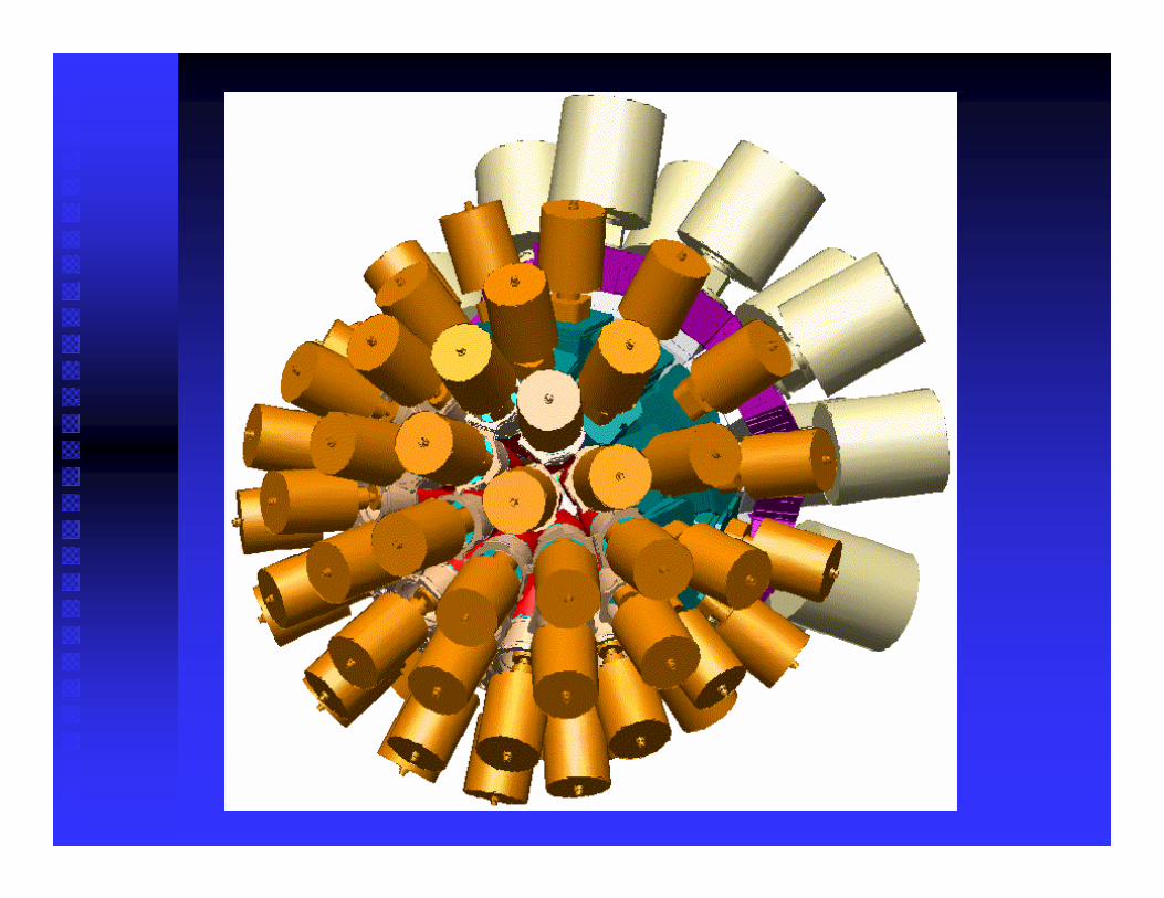
Cross Section of EPOS
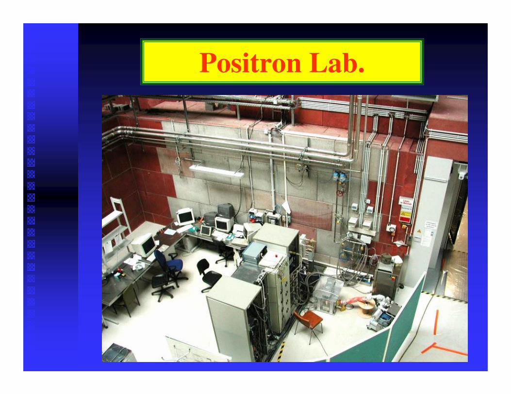
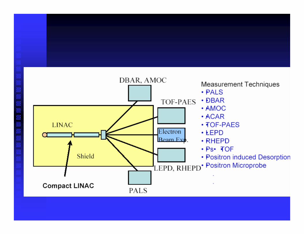
Positron Lab.
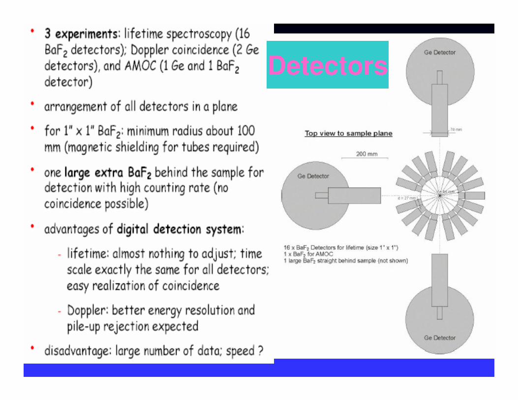
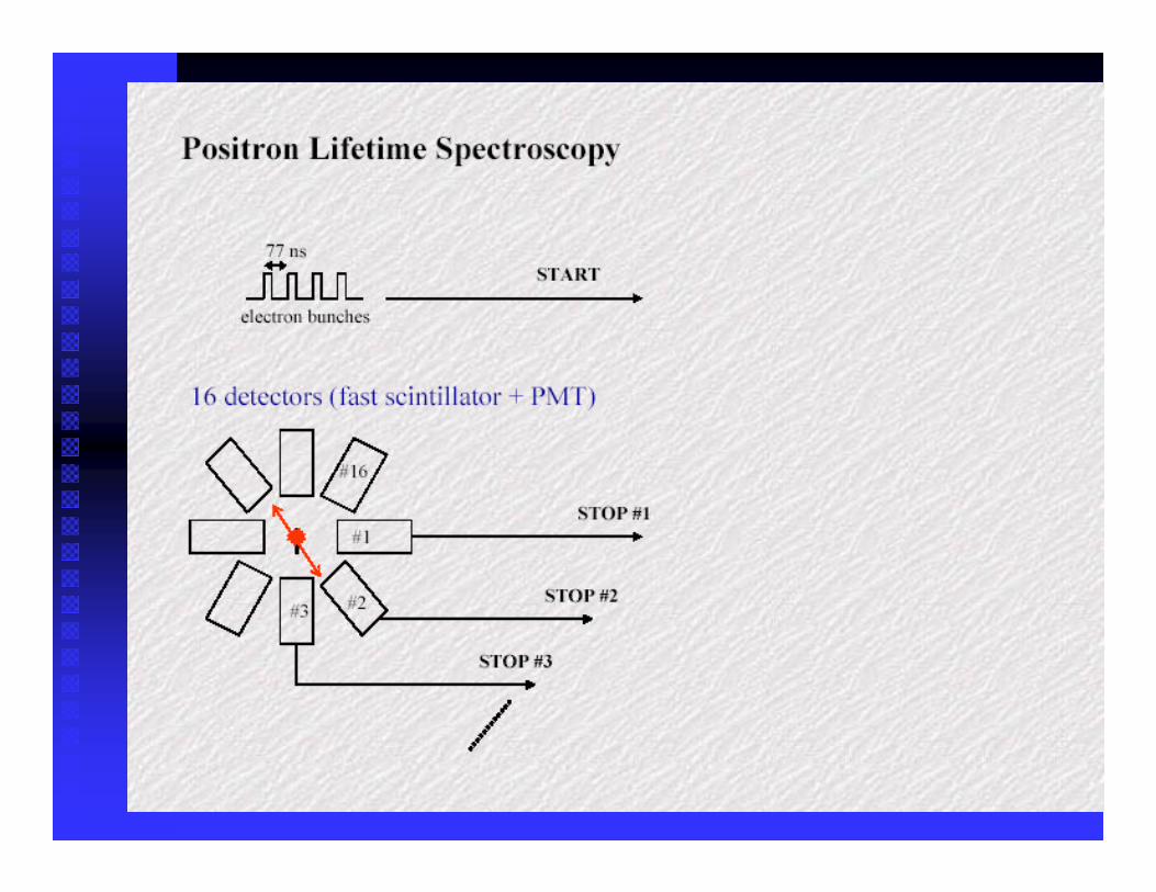
Detectors
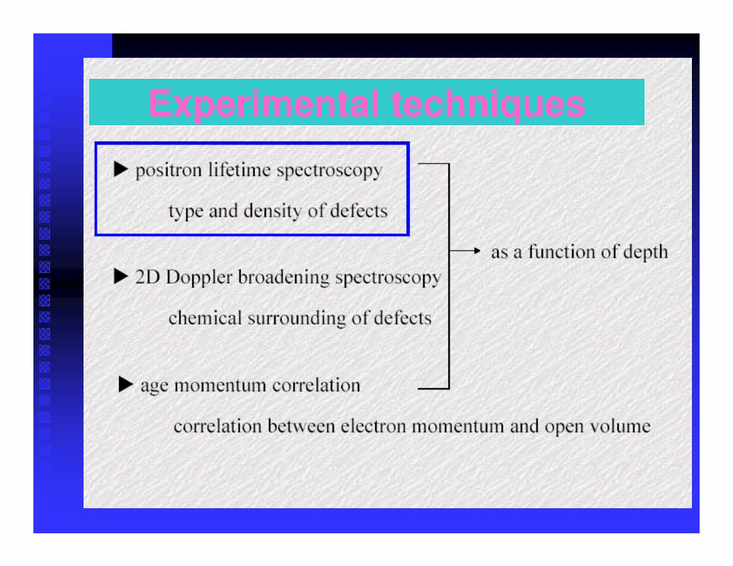
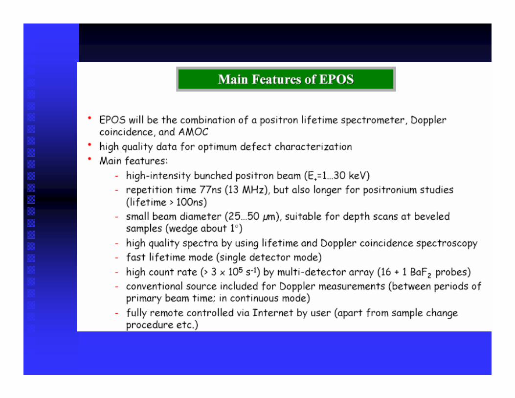
Experimental techniques
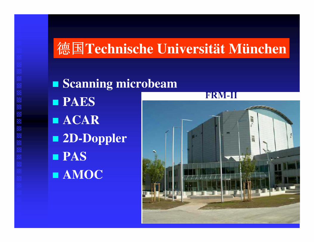
� Scanning microbeam� PAES� ACAR � 2D-Doppler� PAS� AMOC
Technische Universität München
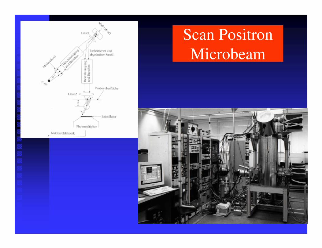
Scan Positron Microbeam
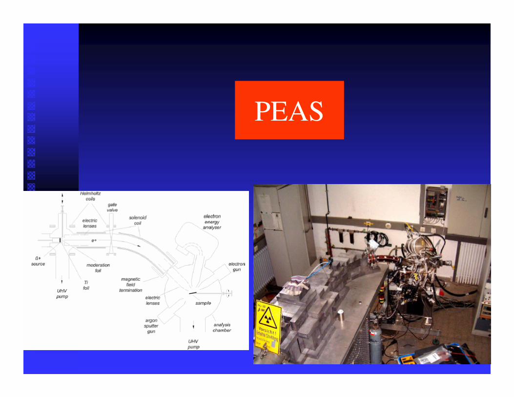
PEAS
Positron in UAS
�� LLNLLLNL�� Univ. of Univ. of MichigenMichigen�� Brandeis Univ.Brandeis Univ.�� University of Missouri University of Missouri -- Kansas CityKansas City
ACAR
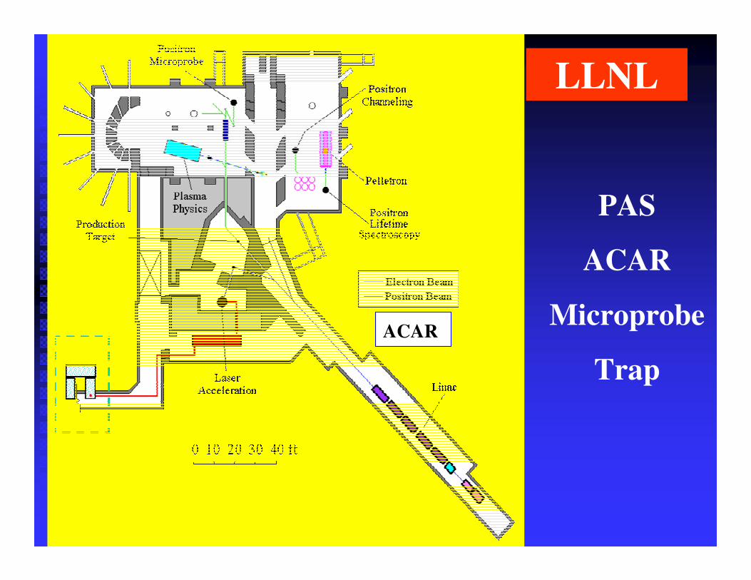
LLNL
PAS
ACAR
Microprobe
Trap
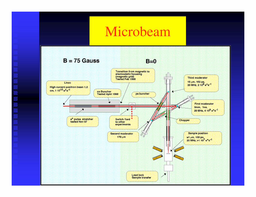
Microbeam
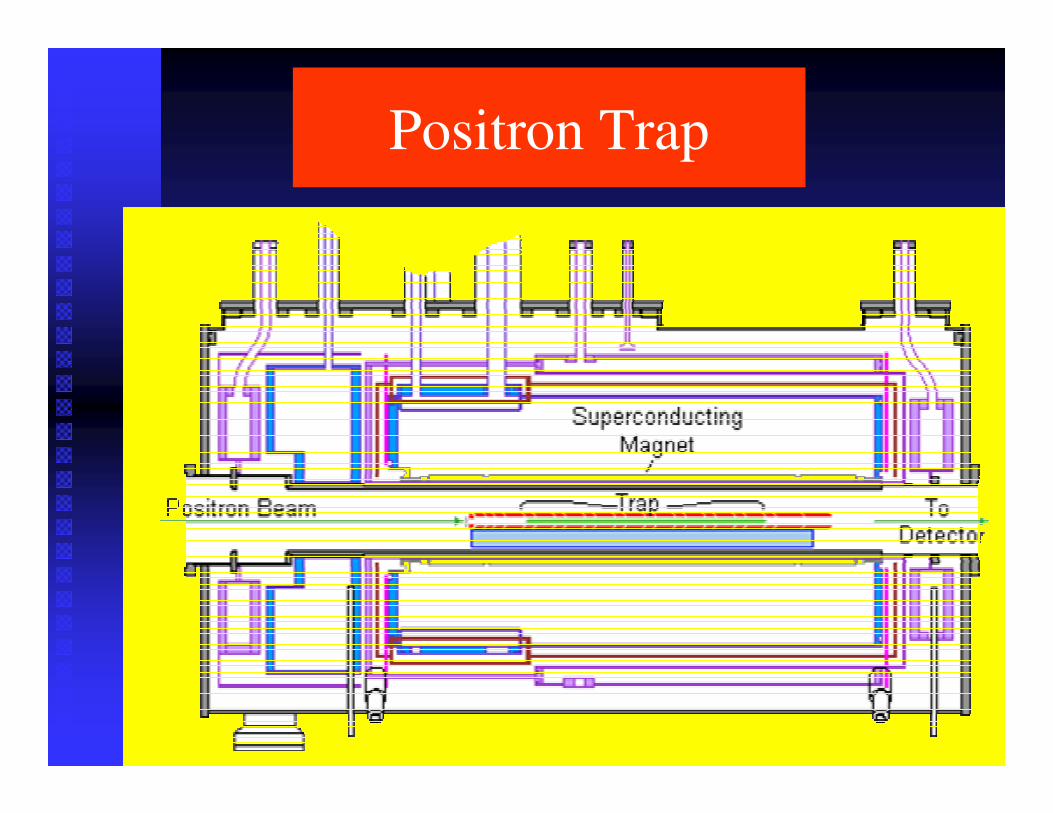
Positron Trap
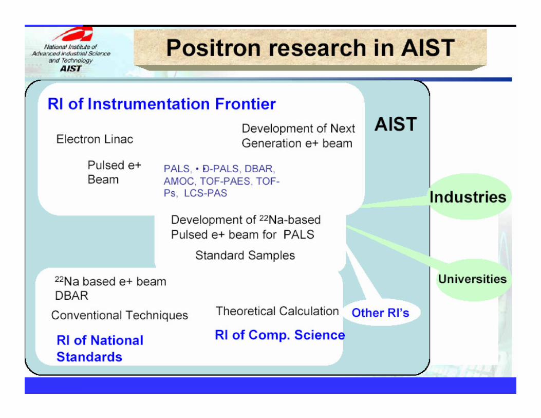
Positron in Japan
�� AISTAIST�� KEKKEK�� JAERIJAERI�� University of TokyoUniversity of Tokyo�� Spring 8Spring 8
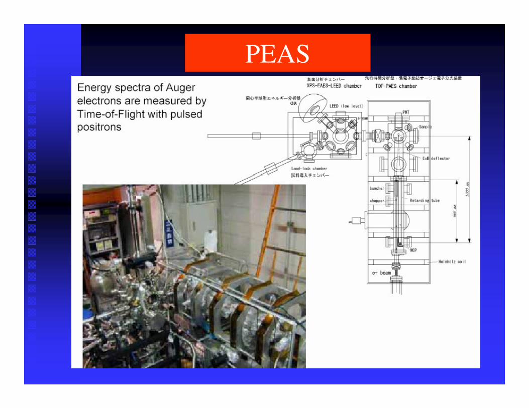
PEAS

Goal of the Cooperative Research
Development of polarized positron source for the future linear collider.
The linear collider project in Japan, formerly known as JLC (Japan Linear Collider), has received a new name GLC (Global Linear Collider).
US-Japan Cooperation in the Field of High Energy Physics
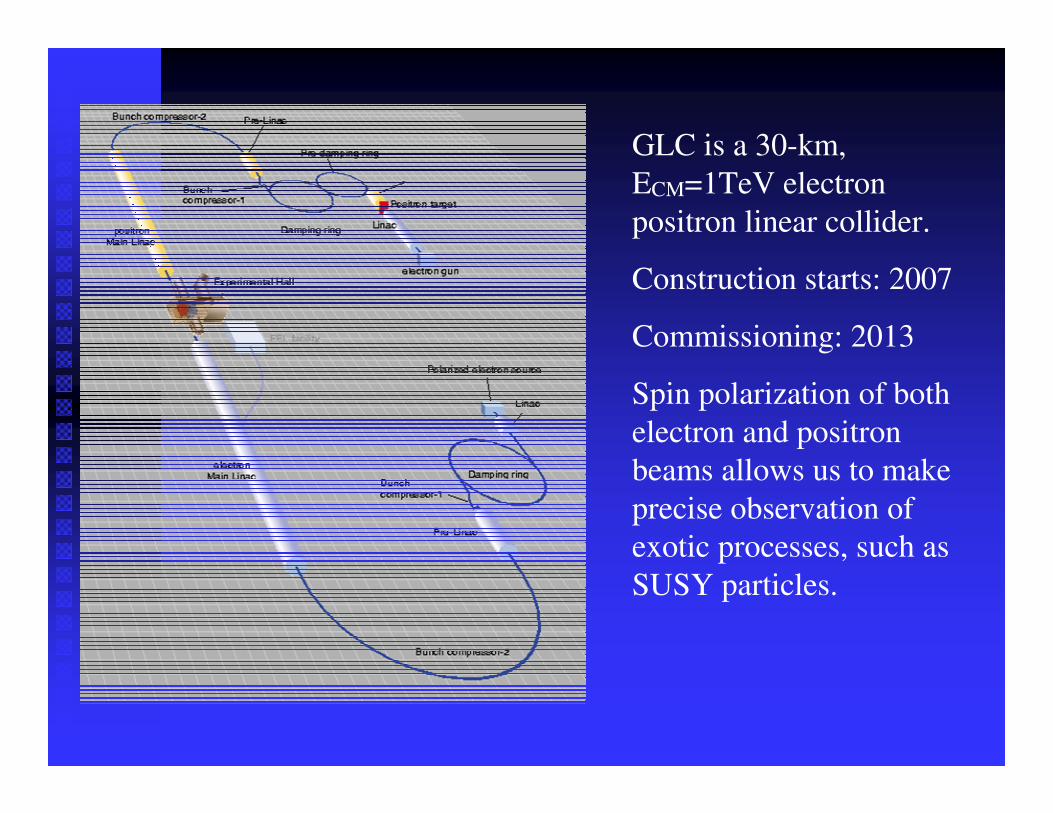
GLC is a 30-km, ECM=1TeV electron positron linear collider.
Construction starts: 2007
Commissioning: 2013
Spin polarization of both electron and positron beams allows us to make precise observation of exotic processes, such as SUSY particles.
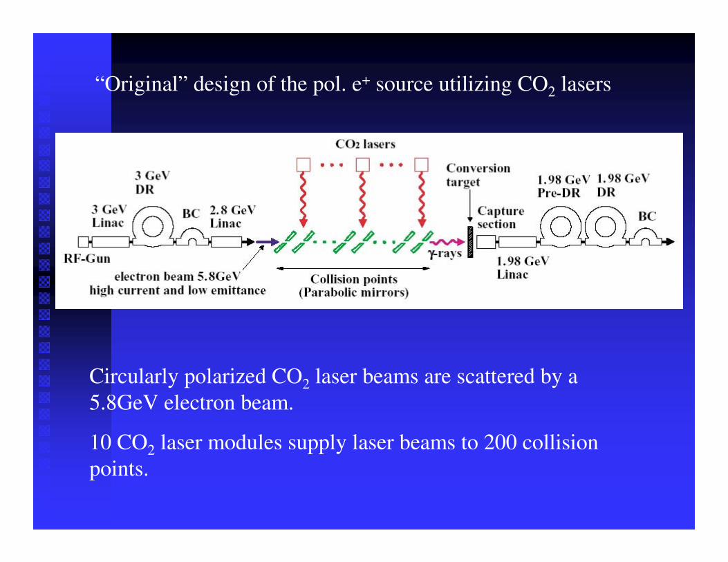
“Original” design of the pol. e+ source utilizing CO2 lasers
Circularly polarized CO2 laser beams are scattered by a 5.8GeV electron beam.
10 CO2 laser modules supply laser beams to 200 collision points.
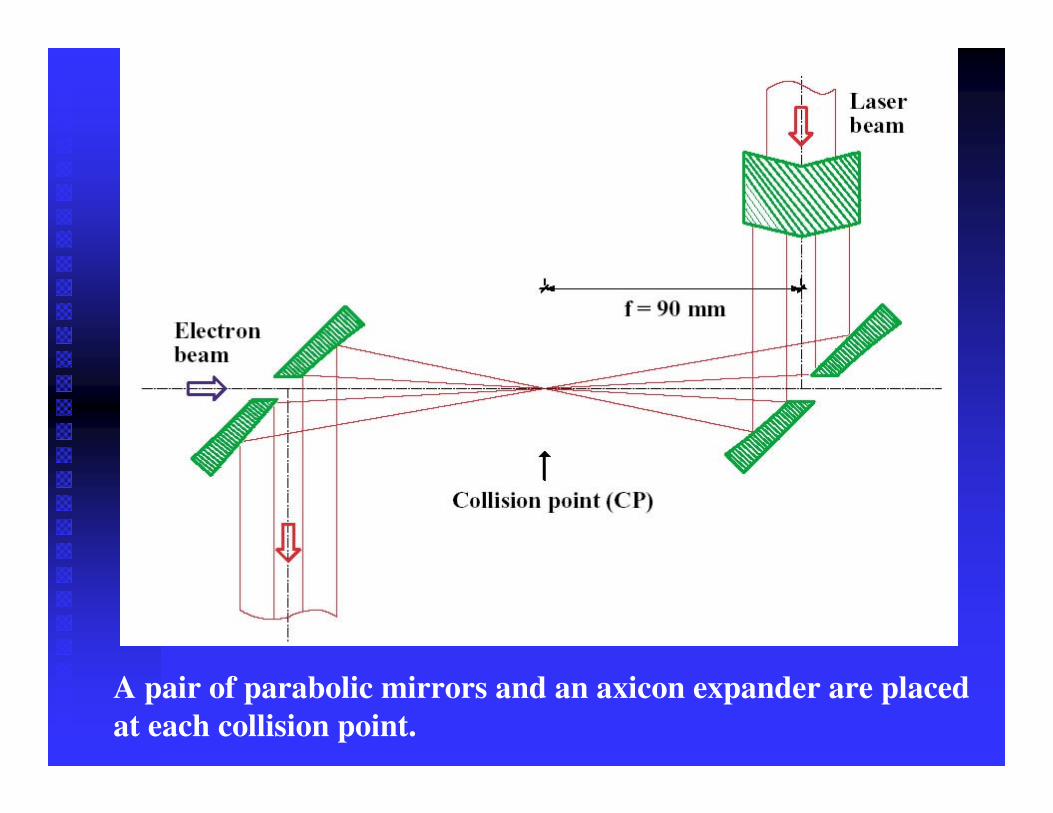
A pair of parabolic mirrors and an axicon expander are placed at each collision point.
��
��
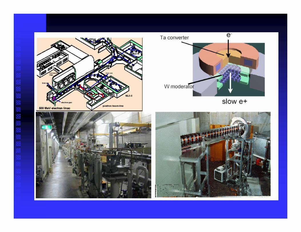
�� 200200MeVMeV LinacLinac
��
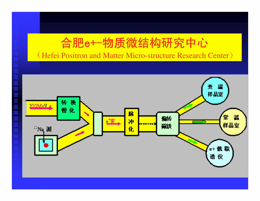
Hefei Positron and Matter Micro-structure Research Center
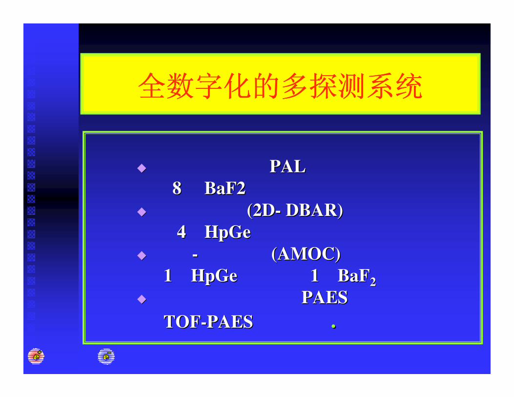
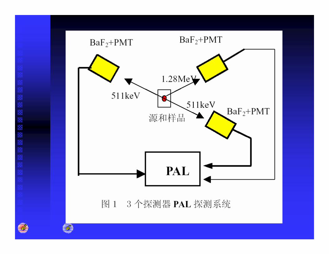
�� PALPAL8 8 BaF2 BaF2
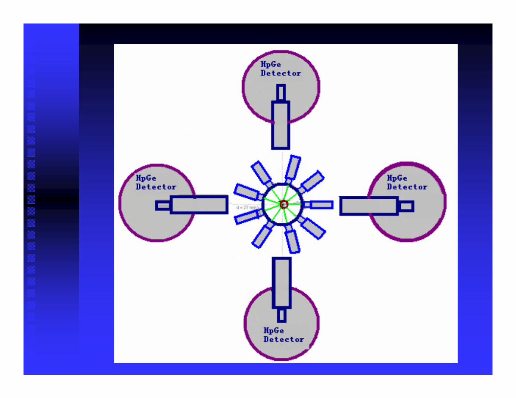
�� (2D(2D-- DBAR)DBAR)44 HpGeHpGe
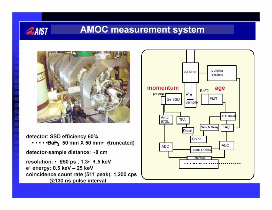
�� -- (AMOC) (AMOC) 11 HpGeHpGe 11 BaFBaF22
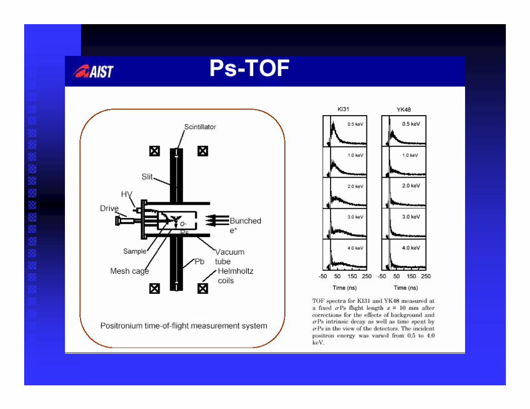
�� PAESPAESTOFTOF--PAES PAES ..
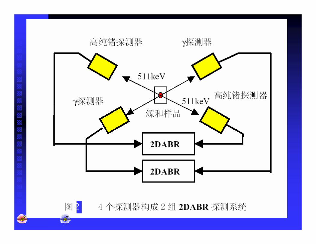
2
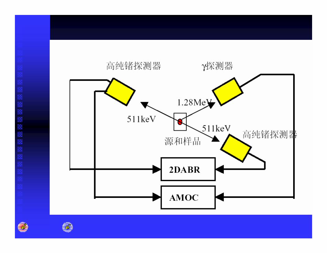
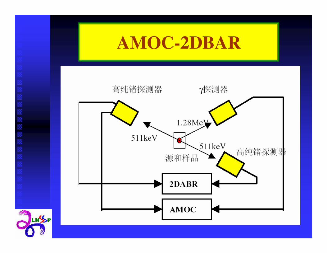
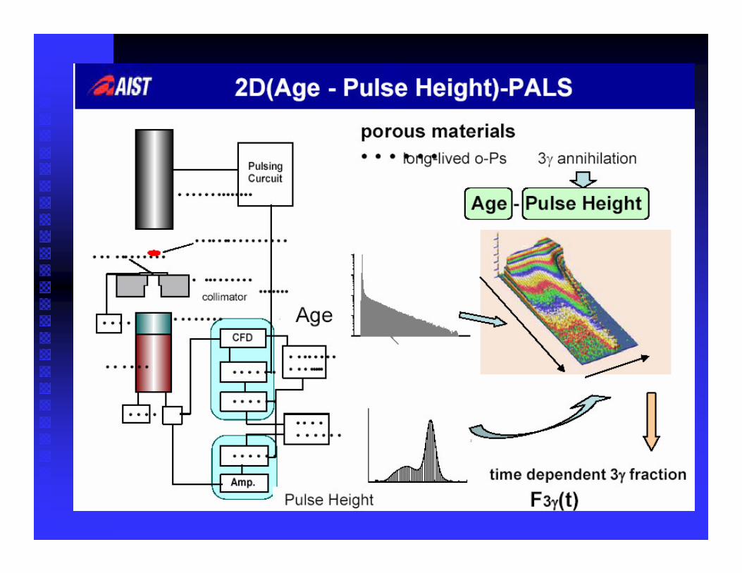
AMOC-2DBAR

��������