Embed Size (px)
DESCRIPTION
magnetic pick up
Citation preview
Product Specification 36563
Magnetic Pickups
SAE THREADS
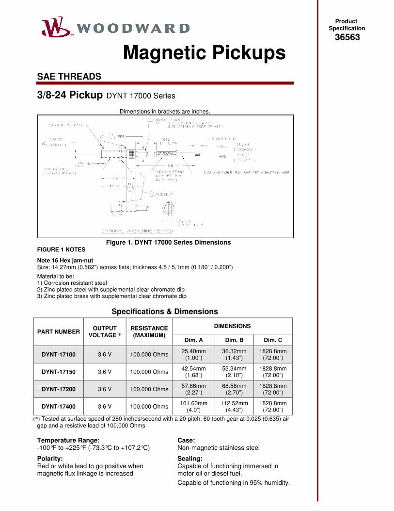
3/8-24 Pickup DYNT 17000 Series
Dimensions in brackets are inches.
Figure 1. DYNT 17000 Series Dimensions
FIGURE 1 NOTES
Note 16 Hex jam-nut Size: 14.27mm (0.562”) across flats; thickness 4.5 / 5.1mm (0.180” / 0.200”) Material to be: 1) Corrosion resistant steel 2) Zinc plated steel with supplemental clear chromate dip 3) Zinc plated brass with supplemental clear chromate dip
Specifications & Dimensions
DIMENSIONS PART NUMBER OUTPUT
VOLTAGE * RESISTANCE (MAXIMUM)
Dim. A Dim. B Dim. C
DYNT-17100 3.6 V 100,000 Ohms 25.40mm (1.00”)
36.32mm (1.43”)
1828.8mm (72.00”)
DYNT-17150 3.6 V 100,000 Ohms 42.54mm (1.68”)
53.34mm (2.10”)
1828.8mm (72.00”)
DYNT-17200 3.6 V 100,000 Ohms 57.66mm (2.27”)
68.58mm (2.70”)
1828.8mm (72.00”)
DYNT-17400 3.6 V 100,000 Ohms 101.60mm (4.0”)
112.52mm (4.43”)
1828.8mm (72.00”)
(*) Tested at surface speed of 280 inches/second with a 20-pitch, 60-tooth gear at 0.025 (0.635) air gap and a resistive load of 100,000 Ohms Temperature Range: -100°F to +225°F (-73.3°C to +107.2°C) Polarity: Red or white lead to go positive when magnetic flux linkage is increased
Case: Non-magnetic stainless steel Sealing: Capable of functioning immersed in motor oil or diesel fuel. Capable of functioning in 95% humidity.
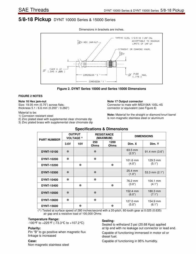
SAE Threads DYNT 10000 Series & DYNT 15000 Series 5/8-18 Pickup
5/8-18 Pickup DYNT 10000 Series & 15000 Series
Dimensions in brackets are inches.
Figure 2. DYNT Series 10000 and Series 15000 Dimensions FIGURE 2 NOTES
Note 16 Hex jam-nut Size: 19.05 mm (0.75”) across flats; thickness 5.1 / 6.6 mm (0.200” / 0.260”) Material to be: 1) Corrosion resistant steel 2) Zinc plated steel with supplemental clear chromate dip 3) Zinc plated brass with supplemental clear chromate dip
Note 17 Output connector Connector to mate with MS3106A 10SL-4S connector or equivalent (see Figure 8) Note: Material for the straight or diamond knurl barrel is non-magnetic stainless steel or aluminum
Specifications & Dimensions OUTPUT
VOLTAGE * RESISTANCE (MAXIMUM) DIMENSIONS
PART NUMBER 3.6V 10V 250
Ohms 1200
Ohms Dim. X Dim. Y
DYNT-10100 � � 63.5 mm (2.5”) 91.4 mm (3.6”)
DYNT-10200 � �
DYNT-15200 � �
101.6 mm (4.0”)
129.5 mm (5.1”)
DYNT-10300 � � 25.4 mm (1.0”) 53.3 mm (2.1”)
DYNT-10400 � �
DYNT-15400 � �
76.2 mm (3.0”)
104.1 mm (4.1”)
DYNT-10500 � � 152.4 mm (6.0”)
180.3 mm (7.1”)
DYNT-10600 � �
DYNT-15600 � �
127.0 mm (5.0”)
154.9 mm (6.1”)
(*) Tested at surface speed of 280 inches/second with a 20-pitch, 60-tooth gear at 0.025 (0.635) air gap and a resistive load of 100,000 Ohms
Temperature Range: -100°F to +225°F (-73.3°C to +107.2°C) Polarity: Pin "B" to go positive when magnetic flux linkage is increased Case: Non-magnetic stainless steel
Sealing: Sealed to withstand 3 psi (20.68 Kpa) applied at tip end with no leakage out connector or lead end. Capable of functioning immersed in motor oil or diesel fuel. Capable of functioning in 95% humidity.
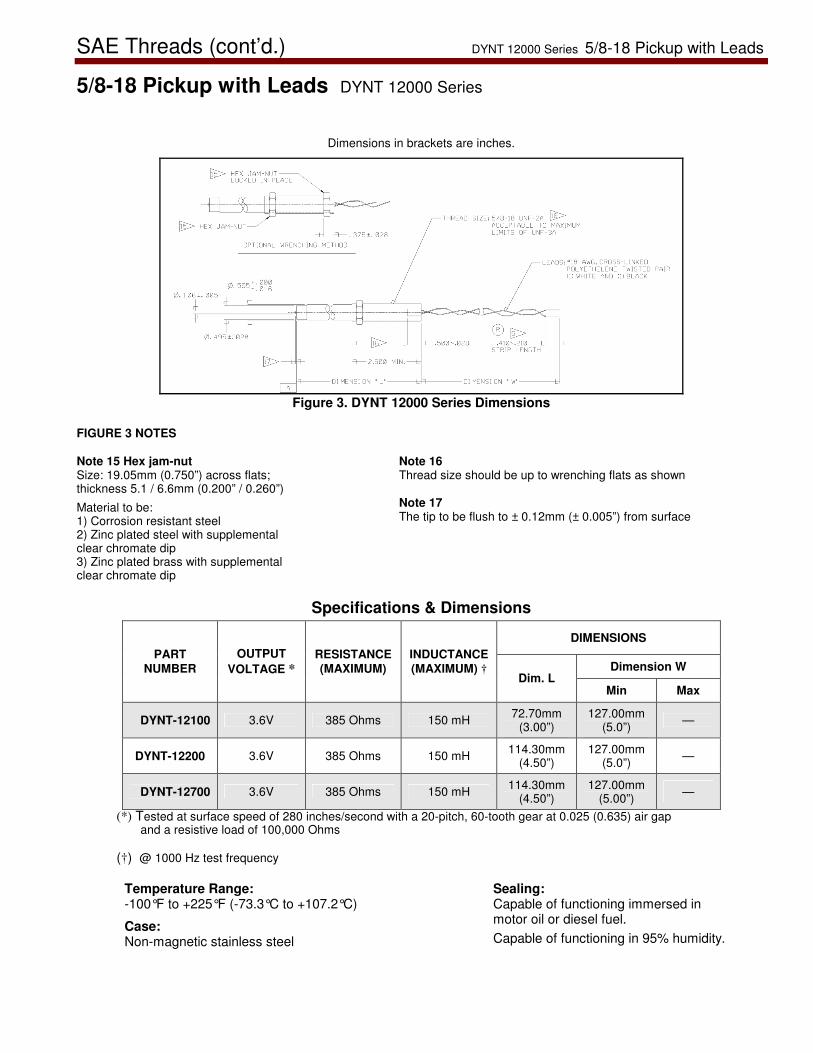
SAE Threads (cont’d.) DYNT 12000 Series 5/8-18 Pickup with Leads
5/8-18 Pickup with Leads DYNT 12000 Series
Dimensions in brackets are inches.
Figure 3. DYNT 12000 Series Dimensions
FIGURE 3 NOTES
Note 15 Hex jam-nut Size: 19.05mm (0.750”) across flats; thickness 5.1 / 6.6mm (0.200” / 0.260”) Material to be: 1) Corrosion resistant steel 2) Zinc plated steel with supplemental clear chromate dip 3) Zinc plated brass with supplemental clear chromate dip
Note 16 Thread size should be up to wrenching flats as shown Note 17 The tip to be flush to ± 0.12mm (± 0.005”) from surface
Specifications & Dimensions
DIMENSIONS
Dimension W PART
NUMBER OUTPUT
VOLTAGE * RESISTANCE (MAXIMUM)
INDUCTANCE (MAXIMUM) †
Dim. L Min Max
DYNT-12100 3.6V 385 Ohms 150 mH 72.70mm (3.00”)
127.00mm (5.0”) —
DYNT-12200 3.6V 385 Ohms 150 mH 114.30mm (4.50”)
127.00mm (5.0”) —
DYNT-12700 3.6V 385 Ohms 150 mH 114.30mm (4.50”)
127.00mm (5.00”) —
(*) Tested at surface speed of 280 inches/second with a 20-pitch, 60-tooth gear at 0.025 (0.635) air gap and a resistive load of 100,000 Ohms
(†) @ 1000 Hz test frequency
Temperature Range: -100°F to +225°F (-73.3°C to +107.2°C) Case: Non-magnetic stainless steel
Sealing: Capable of functioning immersed in motor oil or diesel fuel. Capable of functioning in 95% humidity.
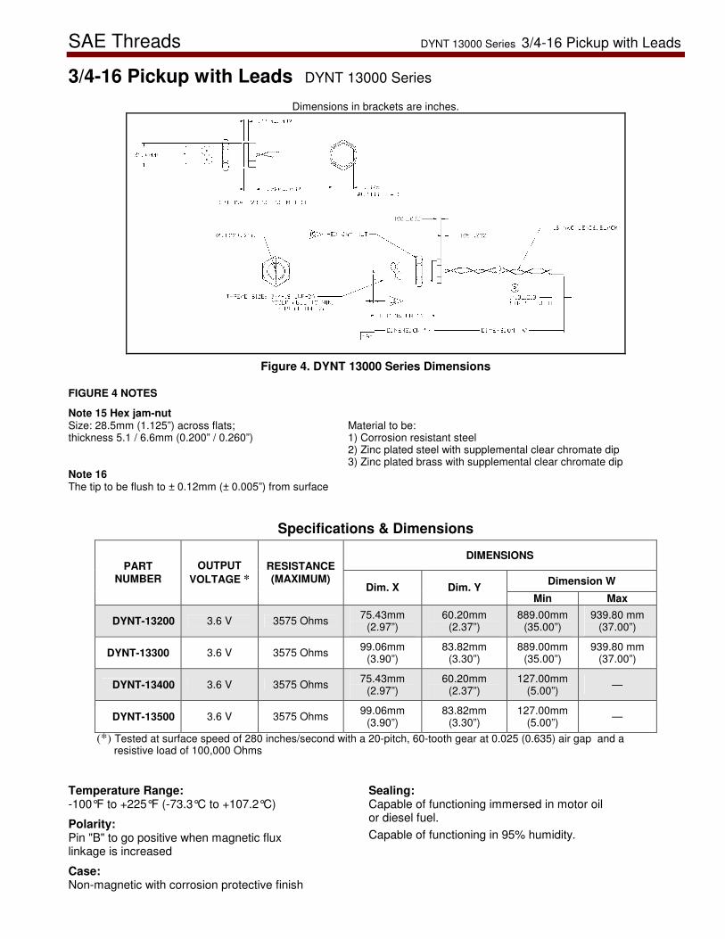
SAE Threads DYNT 13000 Series 3/4-16 Pickup with Leads
3/4-16 Pickup with Leads DYNT 13000 Series
Dimensions in brackets are inches.
Figure 4. DYNT 13000 Series Dimensions
FIGURE 4 NOTES
Note 15 Hex jam-nut Size: 28.5mm (1.125”) across flats; thickness 5.1 / 6.6mm (0.200” / 0.260”)
Material to be: 1) Corrosion resistant steel 2) Zinc plated steel with supplemental clear chromate dip 3) Zinc plated brass with supplemental clear chromate dip
Note 16 The tip to be flush to ± 0.12mm (± 0.005”) from surface
Specifications & Dimensions
DIMENSIONS
Dimension W PART
NUMBER OUTPUT
VOLTAGE * RESISTANCE (MAXIMUM)
Dim. X Dim. Y Min Max
DYNT-13200 3.6 V 3575 Ohms 75.43mm (2.97”)
60.20mm (2.37”)
889.00mm (35.00”)
939.80 mm (37.00”)
DYNT-13300 3.6 V 3575 Ohms 99.06mm (3.90”)
83.82mm (3.30”)
889.00mm (35.00”)
939.80 mm (37.00”)
DYNT-13400 3.6 V 3575 Ohms 75.43mm (2.97”)
60.20mm (2.37”)
127.00mm (5.00”) —
DYNT-13500 3.6 V 3575 Ohms 99.06mm (3.90”)
83.82mm (3.30”)
127.00mm (5.00”) —
(*) Tested at surface speed of 280 inches/second with a 20-pitch, 60-tooth gear at 0.025 (0.635) air gap and a resistive load of 100,000 Ohms
Temperature Range: -100°F to +225°F (-73.3°C to +107.2°C) Polarity: Pin "B" to go positive when magnetic flux linkage is increased Case: Non-magnetic with corrosion protective finish
Sealing: Capable of functioning immersed in motor oil or diesel fuel. Capable of functioning in 95% humidity.
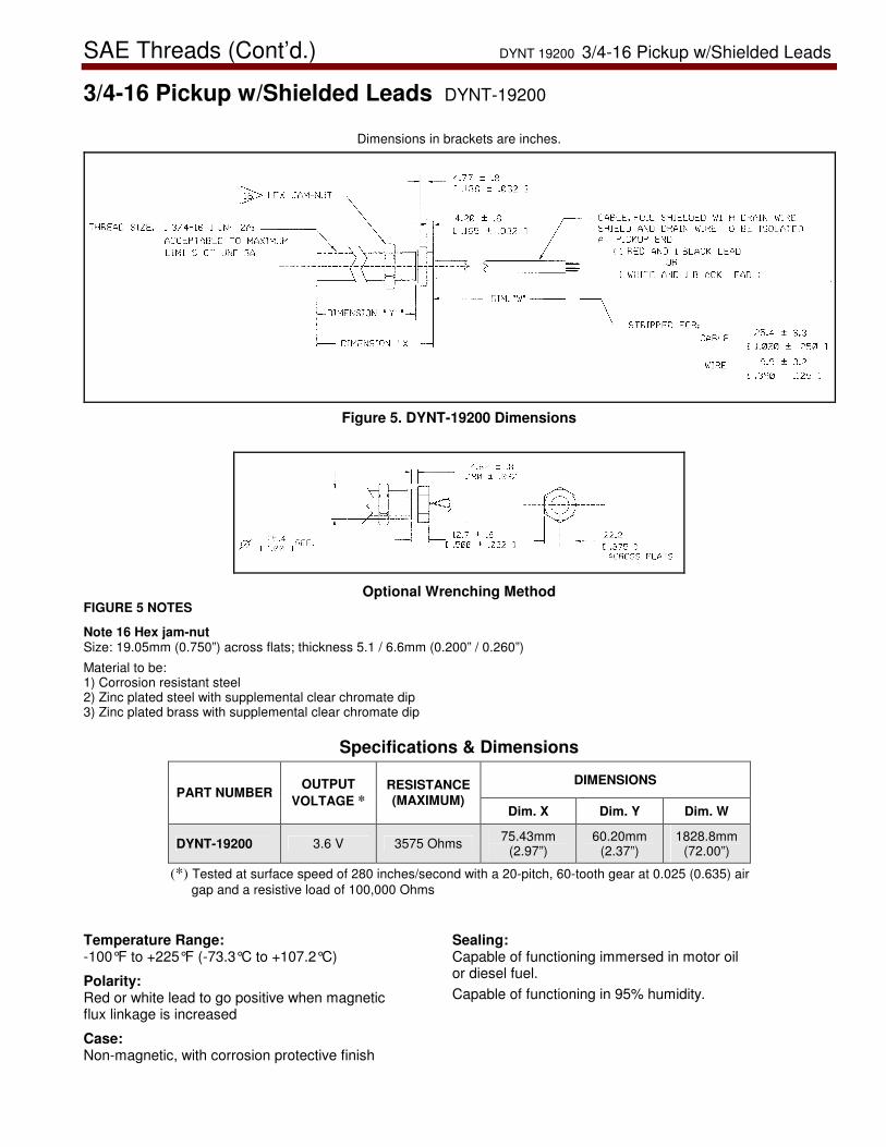
SAE Threads (Cont’d.) DYNT 19200 3/4-16 Pickup w/Shielded Leads
3/4-16 Pickup w/Shielded Leads DYNT-19200
Dimensions in brackets are inches.
Figure 5. DYNT-19200 Dimensions
Optional Wrenching Method FIGURE 5 NOTES
Note 16 Hex jam-nut Size: 19.05mm (0.750”) across flats; thickness 5.1 / 6.6mm (0.200” / 0.260”) Material to be: 1) Corrosion resistant steel 2) Zinc plated steel with supplemental clear chromate dip 3) Zinc plated brass with supplemental clear chromate dip
Specifications & Dimensions
DIMENSIONS PART NUMBER
OUTPUT VOLTAGE *
RESISTANCE (MAXIMUM)
Dim. X Dim. Y Dim. W
DYNT-19200 3.6 V 3575 Ohms 75.43mm (2.97”)
60.20mm (2.37”)
1828.8mm (72.00”)
(*) Tested at surface speed of 280 inches/second with a 20-pitch, 60-tooth gear at 0.025 (0.635) air gap and a resistive load of 100,000 Ohms
Temperature Range: -100°F to +225°F (-73.3°C to +107.2°C) Polarity: Red or white lead to go positive when magnetic flux linkage is increased Case: Non-magnetic, with corrosion protective finish
Sealing: Capable of functioning immersed in motor oil or diesel fuel. Capable of functioning in 95% humidity.
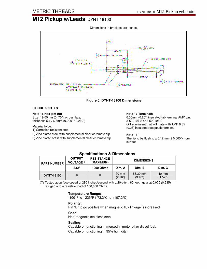
METRIC THREADS DYNT 18100 M12 Pickup w/Leads
M12 Pickup w/Leads DYNT 18100
Dimensions in brackets are inches.
Figure 6. DYNT-18100 Dimensions FIGURE 6 NOTES
Note 16 Hex jam-nut Size: 19.05mm (0. 75”) across flats; thickness 5.1 / 6.6mm (0.200” / 0.260”) Material to be: 1) Corrosion resistant steel 2) Zinc plated steel with supplemental clear chromate dip 3) Zinc plated brass with supplemental clear chromate dip
Note 17 Terminals 6.35mm (0.25”) insulated tab terminal AMP p/n: 3-520107-2 or 3-520106-2 OR equivalent that will mate with AMP 6.35 (0.25) insulated receptacle terminal. Note 18 The tip to be flush to ± 0.12mm (± 0.005”) from surface
Specifications & Dimensions OUTPUT
VOLTAGE * RESISTANCE (MAXIMUM) DIMENSIONS
PART NUMBER 3.6V 1000 Ohms Dim. A Dim. B Dim. C
DYNT-18100 � � 70 mm (2.76”)
88.39 mm (3.48”)
40 mm (1.57”)
(*) Tested at surface speed of 280 inches/second with a 20-pitch, 60-tooth gear at 0.025 (0.635) air gap and a resistive load of 100,000 Ohms
Temperature Range: -100°F to +225°F (-73.3°C to +107.2°C) Polarity: Pin "B" to go positive when magnetic flux linkage is increased Case: Non-magnetic stainless steel Sealing: Capable of functioning immersed in motor oil or diesel fuel. Capable of functioning in 95% humidity.

Metric Threads DYNT 11000 Series & 16000 Series M16 Pickup
M16 Pickup DYNT 11000 Series & 16000 Series
Dimensions in brackets are inches.
Figure 7. DYNT Series 11000 and Series 16000 Dimensions FIGURE 7 NOTES
Note 16 Hex jam-nut DYNT-11000 Series: Size: 24.00-23.67 mm (0.944-0.931”) across flats; thickness 8.00 / 7.42 mm (0.314” / 0.292”)
DYNT-16000 Series: Size: 23.85 mm (0. 0.938”) across flats; thickness 5.1 / 6.6 mm (0.200” / 0.260”) Material to be: 1) Corrosion resistant steel 2) Zinc plated steel with supplemental clear chromate dip 3) Zinc plated brass with supplemental clear chromate dip Note 17 Output connector Connector to mate with MS3106A 10SL-4S connector or equivalent (see Figure 8) Note 18 Output connector The tip to be flush to ± 0.12mm (± 0.005”) from surface Note: Material for the straight or diamond knurl barrel is non-magnetic stainless steel or aluminum

Metric Threads (cont’d.) DYNT 11000 Series & 16000 Series M16 Pickup
DYNT 11000 Series & 16000 Series M16 Pickup
Specifications & Dimensions OUTPUT
VOLTAGE * RESISTANCE (MAXIMUM) DIMENSIONS
PART NUMBER 3.6V 10V 250
Ohms 1200
Ohms Dim. X Dim. Y
DYNT-11100 � �
DYNT-16100 � � 63.5 mm
(2.5”) 91.4 mm (3.6”)
DYNT-11200 � � 101.6 mm (4.0”)
129.5 mm (5.1”)
DYNT-11300 � � 25.4 mm (1.0”) 53.3 mm (2.1”)
DYNT-11400 � � 76.2 mm (3.0”)
104.1 mm (4.1”)
DYNT-11500 � � 152.4 mm (6.0”)
180.3 mm (7.1”)
DYNT-11600 � � 127.0 mm (5.0”)
154.9 mm (6.1”)
(*) Tested at surface speed of 200 inches/second with a 20-pitch, 60-tooth gear at 0.025 (0.635) air gap and a resistive load of 100,000 Ohms
Temperature Range: DYNT 11000 Series: -100°F to +248°F (-73.3°C to +120°C) DYNT 16000 Series: -100°F to +225°F (-73.3°C to +107.2°C) Polarity: Pin "B" to go positive when magnetic flux linkage is increased Case: Non-magnetic stainless steel Sealing: Sealed to withstand 3 psi (20.68 Kpa) applied at tip end with no leakage out connector or lead end. Capable of functioning immersed in motor oil or diesel fuel. Capable of functioning in 95% humidity.

CABLE HARNESS DK81-00X-0-00
For DYNT Series magnetic pickup wire connections using MS-3106A-10SL-4S mating connector
Dimensions in brackets are inches.
Figure 8. DK81-00X-0-00 Cable Harness Dimensions
PART NUMBER DIMENSION B
DK81-001-0-00 3000.0 ± 51.0 mm (118.1 ± 2.0”)
DK81-002-0-00 914.4 ± 51.0 mm (36.0 ± 2.0”)
DK81-003-0-00 1524.0 ± 51.0 mm (60.0 ± 2.0”)
DK81-007-0-00 4267.2 ± 51.0 mm (168.0 ± 2.0”)
DK81-009-0-00 1066.8 ± 51.0 mm (42.0 ± 2.0”)
DK81-010-0-00 1778.0 ± 51.0 mm (70.0 ± 2.0”)
WARNING—OVERSPEED PROTECTION The engine, turbine, or other type of prime mover should be equipped with an overspeed shutdown device to protect against runaway or damage to the prime mover with possible personal injury, loss of life, or property damage.
The overspeed shutdown device must be totally independent of the prime mover control system. An overtemperature or overpressure shutdown device may also be needed for safety, as appropriate.
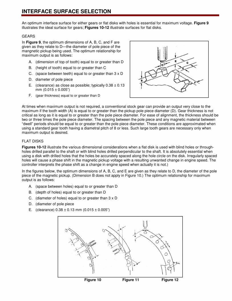
INTERFACE SURFACE SELECTION
An optimum interface surface for either gears or flat disks with holes is essential for maximum voltage. Figure 9 illustrates the ideal surface for gears; Figures 10-12 illustrate surfaces for flat disks. GEARS
In Figure 9, the optimum dimensions of A, B, C, and F are given as they relate to D—the diameter of pole piece of the mangnetic pickup being used. The optimum relationship for maximum output is as follows:
A. (dimension of top of tooth) equal to or greater than D B. (height of tooth) equal to or greater than C C. (space between teeth) equal to or greater than 3 x D D. diameter of pole piece E. (clearance) as close as possible; typically 0.38 ± 0.13
mm (0.015 ± 0.005”) F. (gear thickness) equal to or greater than D
At times when maximum output is not required, a conventional stock gear can provide an output very close to the maximum if the tooth width (A) is equal to or greater than the pickup pole piece diameter (D). Gear thickness is not critical as long as it is equal to or greater than the pole piece diameter. For ease of alignment, the thickness should be two or three times the pole piece diameter. The spacing between the pole piece and any magnetic material between “dwell” periods should be equal to or greater than the pole piece diameter. These conditions are approximated when using a standard gear tooth having a diametral pitch of 8 or less. Such large tooth gears are necessary only when maximum output is desired. FLAT DISKS
Figures 10-12 illustrate the various dimensional considerations when a flat disk is used with blind holes or through-holes drilled parallel to the shaft or with blind holes drilled perpendicular to the shaft. It is absolutely essential when using a disk with drilled holes that the holes be accurately spaced along the hole circle on the disk. Irregularly spaced holes will cause a phase shift in the magnetic pickup voltage with a resulting unwanted change in engine speed. The controller interprets the phase shift as a change in engine speed when actually it is not.) In the figures below, the optimum dimensions of A, B, C, and E are given as they relate to D, the diameter of the pole piece of the magnetic pickup. (Dimension B does not apply in Figure 10.) The optimum relationship for maximum output is as follows:
A. (space between holes) equal to or greater than D B. (depth of holes) equal to or greater than D C. (diameter of holes) equal to or greater than 3 x D D. (diameter of pole piece E. (clearance) 0.38 ± 0.13 mm (0.015 ± 0.005”)
Figure 10 Figure 11 Figure 12

RELATED DOCUMENTATION
Product Specificaton 36533 5/8 and 3/4 Magnetic Pickups
PO Box 1519 Fort Collins CO, USA
80522-1519 1000 East Drake Road Fort Collins CO 80525 Ph: +1 (970) 482-5811 Fax: +1 (970) 498-3058 Distributors & Service Woodward has an international network of distributors and service facilities. For your nearest representative, call the Fort Collins plant or see the Worldwide Directory on our website. Corporate Headquarters Rockford IL, USA Ph: +1 (815) 877-7441 www.woodward.com This document is distributed for informational purposes only. It is not to be construed as creating or becoming part of any Woodward Governor Company contractual or warranty obligation unless expressly stated in a written sales contract. © Woodward 2006 All Rights Reserved
For more information contact: 06/07/M


