Embed Size (px)
Citation preview
IS : 3624 - 1987
Indian Standard
SPECIFICATION FOR PRESSURE AND VACUUM GAUGES
(Second Revision)
Industrial Process Measurement and Control Sectional Committee, ET-DC 6.7 /v
Chairnlun PROF J. K. CHOUDHURY
Jadavpur University, Calcutta
Members Representing SHRI ABHI~IT DE Sett &De, Calcutta SHRI AMITAVA SENG~PTA M. N. Dastur & Co Pvt Ltd, Calcutta
SHRI ACHINTYA KLJMAR BISWAS ( Alternate ) SHRI RS. ARORA Directorate General of Supplies & Disposals,
New Delhi SHRI G. BALARAM Indian Oil Corporation Ltd, New Delhi
SHRI S. B. MATHUR ( Alternate ) SHRI G. BALA SURRAMANIAN Metallurgical & Engineering Consultants ( India )
Ltd ( MECON ). Ranchi . SHRI S. K. MITRA ( Alternate I
,,
SHRI K. R. BANERJEE ’ Instrumentation Ltd, Kota SHRI V. S. RAMADAS ( Alternate )
SHRI J. K. CHATTERJEE Steel Authority of India ( Durganur Steel Plant ), Durgapur _
- _
SHRI CH. SURENDER Department of Atomic Energy, Bombay SHRI S. RAMAKRISHNAN ( Alternate )
COL D. K. DESHPANDE Directorate of Standardization, Ministry of Defence (DGI), New Delhi
SHRI D. P. GOEL Central Scientific Instruments 0 rganizat ion ( CSIR ), Chandigarh
SHRI A. N. AGARWAL ( Alternate ) SHRI R. K. GOLIA Udeyraj & Sons, Bombay
SHRI P. C. GOLIA ( Alternote ) SHRI G. L. KHANDUJA Electronics Corporation of India Ltd, Hyderabad SHRI P. K. KRISHNAMURTHI Institute for Design of Electrical Measuring
Instruments, Bombay DR K. RAMANI ( Alternate )
( Continued on page 2 )
@ Copyright 1988
BUREAU OF INDIAN STANDARDS
This publication is protected under the Indian Copyright Acr ( XIV of 1957 ) and reproduction in whole are in part by any means except with written permission of the publisher shall be deemed to be an infringement of copyright under the said Act.
IS:3624-1987
( Continnedfrornpuge 1 )
Members Representing
SHRI B. MUKHOPADHYA National Test House, Calcutta SHRI B. PYNE Calcutta Electric SUPPlY Corporation
( India ) Ltd, Calcutta SHR~ A. GHOSH ( Alfernafe )
SHRI D. V. S. RAIU Elico Pvt Ltd, Hyderabad SHRI T. R. NAGARAJAN( Alternate)
SHRI S. RAMANATHAN lndian Drugs & Pharmaceuticals Ltd, Gurgaon SHRI RAMDAS KISSENDAS Indian Petrochemicals Corporation Ltd, Vadodara
SHRX S. K. SHARMA ( Alternafe ) DR N. J. RAO Institute of Paper Technology, Saharanpur
DR S.-K. AGARWAL ( AIternate ) SHRI K. P. SARMA Projects & Development India Ltd, Sindri
SHRI V. N. SRIVAWAVA ( Alternate ) SHRI M. S. SHEY~Y Tata Consulting Engineers, Bombay
SHRI K. G. SRINIVASAN ( Alternate ) SHRI S. P. SURI National Physical Laboratory ( CSIR), New Delhi
DR A. F. CHHAPGAR ( Alternate ) SHRI K. K. TANEJ~ Directorate General of Technical Development,
New Delhi SHRI MOHANJEET SINGH ( Alternate )
SHRI M. G. TOSHNIWAL Toshniwal Industries Pvt Ltd, Ajmer SHRI S. C. MAHESHWARI ( Alternate )
SHRI J. UDANI Procorn Engineers, Calcutta SHRI M. BANDYOPADHYAY (Alternate )
SHFZI R. VEERARAGHAVAN Beacon Rotork Controls Ltd, Madras SHRI N. SRIRAMAN( Alternate )
SHRI A. K. VERMA Engineers India Ltd, New Delhi SHR~ R. BHANOT ( Alternate )
SHRI H. C. VEKMA As;eat;tgrstrument Manufacturers (I) Pvt Ltd,
SHRI M. D. NAIR ( Alternate ) SHRI S. P. SACHDEV, Director General, BIS ( Ex-oficcio Member )
Director ( Elec tech )
Secretary SHRI B. K. MAHATA
Joint Director ( Elec tech ), BIS
IS : 3624 - 1987
Indian Standard SPECIFICATIO-N FOR
PRESSURE AND VACUUM GAUGES
(Second Revision)
0. FOREWORD
0.1 This Jndian Standard ( Second Revision ) was adopted by the Bureau of Indian Standards on 27 May 1987, after the draft finalized by the Indus- trial Process Measurement and Control Sectional Committee had been approved by the Electrotechnical Division Council.
0.2 This standard was first published in 1966 which was revised in 1979 to make the standard more comprehensive by including the various pressure responsive elements used in pressure and vacuum gauges, other than bour- don tube.
0.3 The second revision includes~various modifications and addition of new requirements on main parameters and metrological characteristics. The requirements of shock test have also been modified in this revised standard.
0.4 Jn preparing the revised standard, data has been received from Insti- tute for Design of Electrical Measuring Instruments, Bombay.
0.5 For the purpose of deciding whether a particular requirement of this standard is complied with, the final value, observed or calculated, expres- sing the result of a test, shall be rounded off in accordance with IS : 2 - 1960*. The number of significant places retained in the rounded off value should be the same as that of the specified value in this standard.
1. SCOPE
1.1 This standard covers the requirements of dial type indicating pressure gauges, vacuum gauges and compound gauges using elastic pressure responsive elements, such as bourdon tube, capsule, bellows or diaphragm. This standard also includes the requirements of test gauges.
*Rules for rounding off numerical values ( revised ).
IS:3624 - 1987
2. NOMENCLATURE
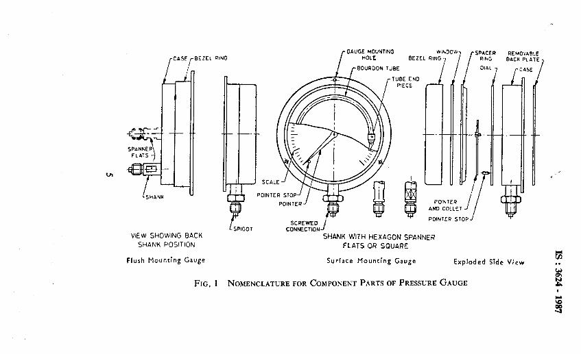
2.1 The nomenclature for the various parts of a gauge shall be as given in Fig. 1 and 2.
2.2 The nomenclature for the various types of gauges with respect to method of mounting shall be as given in Fig. 3 to 5.
3. TERMINOLOGY
3.0 For the purpose of this standard, the following definitions shall apply.
3.1 Basic Gauge Definitions
3.1.1 Pressure Gauge - A gauge to measure and indicate pressure greater than ambient using ambient pressure as the datum point. Ambient pressure is the pressure surrounding the measuring element.
3.1.2 Vacuum Gauge - A gauge to measure and indicate pressure less than ambient using ambient pressure as the datum point.
3.1.3 Compound Gauge -- A gauge to measure and indicate pressure both greater than and less than ambient using ambient pressure as the datum point.
3.1.4 Absolute Pressure Gauge - A gauge to measure and indicate pres- sure above zero absolute pressure using absolute zero pressure as the datum point.
3.1.5 Di’rential Gauge - A gauge having two connections and a means to measure and indicate the difference between two pressures.
3.2 Specific Gauge Service Classification
3.2.1 Test Gauge - A gauge designed to check the accuracy of other gauges or pressure actuated devices.
3.2.2 Industrial Gauge - A gauge of a specified order of accuracy intended for general industrial use.
3.2.3 Receiver Gauge - A gauge designed to measure and indicate the output signal from a pneumatic transmitter. It is calibrated in terms of the transmitter output. The dial may be graduated in units of pressure, temperature flow, level, etc, corresponding to the transmitter input.
3.2.4 Refrigerant Gauge - A gauge designed to measure and indicate the pressure of refrigerants other than ammonia. The dial markings include the service using REFRIGERANT or ‘R’ and the applicable refrigerant number. They also include the equivalent temperature scale marking.
4
,- GAUGE MOUNTING WINDOW,
/
CASE
L SHANK
: B r EZEL RING
c SPIGOT CONNECT!ON-’
VIEW SHOWING BACK SHANK WITH HEXAGON SPANNER SHANK POSITION FLATS OR SQUARE
Flush Mounting Gauge Surface Mounting Gauge
HOLE BEZEL RIH
f BOUROONTUBE
TUBE END PIECE
POINTER STOP
SCREWED /
IG , [SPACER REMOVABLE
RING BACK PLATE,
I DI
t i
POINTER AND COLLET
// POINTER STOP
AL
7 rCA5E /
Exploded Side View @I
FIG, 1 NOMENCLATURE FOR COMPONENT PARTS OF PRESSURE GAUGE

IS : 3624 - 1987
Concentric Scale
Horizon*al Edgewise Scale
Eccentric Scale
VERTICAL EOGE WISE SCALE
Vertical Edgewise Scale
FIG. 2 CONFIGURATION OF SZALES FOR PRESSURE GAUGES
With Bottom Connection With Back Connection
FIG. 3 DIRECT MOUNTING GAUGES
6
IS : 3624 - 1987
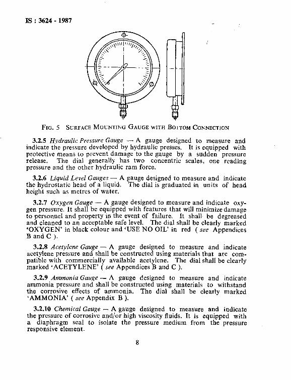
FIG. 5 SURFACE MOUNTING GAUGE WITH BOTTOM CONNECTION
3.2.5 Hydraulic Pressure Gauge - A gauge designed to measure and indicate the pressure developed by hydraulic presses. It is equipped with protective means to prevent damage to the gauge by a sudden pressure release. The dial generally has two concentric scales, one reading pressure and the other hydraulic ram force.
3.2.6 Liquid Level Gauges - A gauge designed to measure and indicate the hydrostatic head of a liquid. The dial is graduated in units of head height such as metres of water.
3.2.7 Oxygen Gauge .- A gauge designed to measure and indicate oxy- gen pressure. It shall be equipped with features that will minimize damage to personnel and property in the event of failure. and cleaned to an acceptable safe level.
It shall be degreased The dial shall be clearly marked
‘OXYGEN’ in black colour and ‘USE NO OIL’ in red ( see Appendices B and C j.
3.2.8 Acetylene Gauge - A gauge designed to measure and indicate acetylene pressure and shall be constructed using materials that are com- patible with commercially available acetylene. The dial shall be clearly marked ‘ACETYLENE’ ( see Appendices B and C ).
3.2.9 Ammonia Gauge - A gauge designed to measure and indicate ammonia pressure and shall be constructed using materials to withstand the corrosive effects of ammonia. The dial shall be clearly marked ‘AMMONIA’ ( see Appendix B ).
3.2.10 Chemical Gauge - A gauge designed to measure and indicate the pressure of-corrosive and/or high viscosity fluids. It is equipped with a diaphragm seal to isolate the pressure medium from the pressure responsive element.
8
‘.
3.3Pressure Elements
IS:3624 -1987
3.3.1 Bourdon Tube - A pressure seusing element in the form of a curved tube which changes its curvature with changes in internal pressures.
3.3.2 Bellows - It is an axially elastic cylinder with deep folds or convolutions which expands or contracts axially witb pressure applied internally or externally. The bellows may be used unopposed or it may be restrained by an opposing spring.
3.3.3 Capsule - It is an element formed by bonding two diaphragms at their periphery. The element may consist of one or more such capsules connected together to obtain large deflections for a particular pressure.
3.3.4 Diaphragm - A flat or corrugated circular metallic disc which deflects with pressure. This is, however, different from the slack dia- phragm where the flexible non-metallic diaphragm is always opposed by a spring or other elastic member which determines its deflection versus pressure characteristics.
3.4 Method of Mounting
3.4.1 Direct Mounting Gauge - A gauge which is mounted and support- ed by its screwed connection. The screwed connection may be at the bottom of the periphery of the case ( direct mounting gauges with bottom connection ) or at the back of the case ( direct mounting gauges with back connection ) ( see Fig. 3 ).
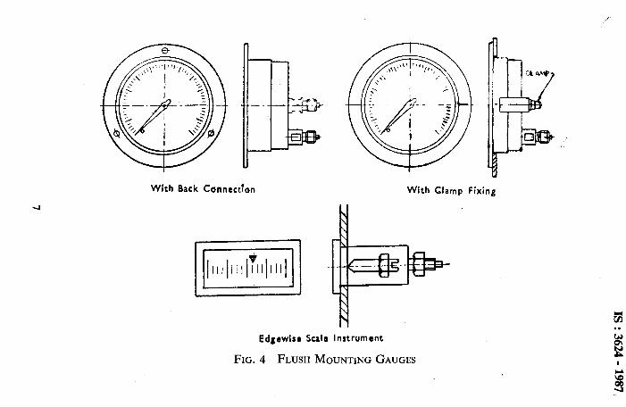
3.4.2 Flush Mounting Gauge - A guage intended for mounting in a panel, the greater portion of the case being recessed in the panel, so that, the front of the gauge, after mounting, is virtually flush with the panel. The screwed connection is at the back of the gauge. The gauge may be mounted and supported by means of a flange at the front of the gauge or by means of a clamp attached to the back of the case and acting against the back of the panel ( see Fig. 4 ).
3.4.3 Surface Mounting Gauge - A gauge intended for mounting on the surface of a panel, the gauge projecting forward therefrom, and which is mounted and supported by means of a flange at the rear of the case. The screwed connection is customarily at the bottom of the periphery of the case ( see Fig. 5 ),
3.5 Components
3.5.1 Bafle H’all - A barrier between the pressure sensing element and the dial so disposed that, in the event of a leakage or burst in the pres- sure responsive element, the blast would be dissipated away from the front.
9
IS : 3624 - 1987
3.5.2 Bezel Ring - The ring fitted to and removable from the case, which holds or retains window to the case.
3.5.3 Blow-Out Device - A safety device incorporated in the case or back plate to permit the rapid and safe dissipation of internal pressure in the event of a leakage or burst in the pressure sensing element.
3.5.4 Case - The outer casing which contains the pressure responsive element and the movement, by custom of the trade, the term case does not include the bezel ring and spacer, nor the window, nor the back plate, if this is removable.
3.5.5 Connecting Link - That part of the movement which is connected to the free end of the pressure responsive element.
3.5.6 Connection - The terminal part of a guage which may be screwed or flanged.
3.5.7 Dial - The plate upon which the scale is marked.
3.5.8 Element Anchorage - That part to which the fixed end of the pressure responsible element is attached, and which may be integral with the shank or may be directly or indirectly connected with the shank by a pressure-conducting system.
3.5.9 Movement - The assembly by which the movement of the free end of the pressure responsive element is multiplied and communicated to the pointer spindle.
3.5.10 Pointer - The index, by the position of which, in relation to the scale, the value of the measured pressure or vacuum is indicated.
3.5.11 Pointer Stop - A screw, stud or other projection fitted to limit the travel of the pointer.
NOTE - It is not the function of a pointer stop to act as an overload stop.
3.5.12 Removable Back Plate - A plate at the back of the case, which is removable for the purpose of giving access to the interior.
NOTE - A removable back plate must not be confused with a blow-out device.
3.5.13 Scale - The graduations and related numerals on the dial. These may be concentric, eccentric or edgewise. Concentric scale forms a major part of a circle ( an angle of approximately 270” ), with the pointer spindle at the centre and the pointer radial to the scale. Eccentric scale forms a small part of a circle and in which the pointer is radial to the scale,~but the centre of rotation of the pointer is not concentric with the scale. Edgewise scale is a graduation on a rectangular dial bent in the form of an arc with the pointer spindle as centre ( see Fig. 2 ).
10
I’ IS : 3624 - 1987
3.5.14 Shank - That part of the gauge which includes the screwed con- nection, the spanner flats, the spigot and the inlet orifice.
3.5.15 Window - The transparent front through which the dial is observed.
3.5.16 Zero Adjustment - A device which sets the pointer at the zero of the scale without removing the pointer, at ambient pressure.
3.6 Miscellaneous Definitions
3.6.1 Nominal Size - The nominal size of a guage is the overall dia- meter or length of the dial.
3.6.2 Over-range Protection -A device provided to protect the measur- ing element in the event of overpressure and also to prevent disengage- ment of the movement gearing. This may be in the form of internal stops.
4. UNIT OF PRESSURE AND VACUUM
4.1 For the purpose of this standard, the unit of pressure shall be the Pascal ( Pa ) or its multiples (kPa ) or ( MPa ) or the bar.
NOTE - 1 Pascal ( Pa ) = 1 N/ma = 1O-5 bar 1 kilopascal ( kPa ) = lo-¶ bar 100 kilopascal = 1 bar 1 megapascal ( MPa ) = 10 bar 1 kgf/cd = 98’066 5 kPa
4.2 For ranges below 1 bar, the units in millimetre of water column ( mmH,O ) or milli bar may also be used.
5. MAIN PARAMETERS
5.1 Limits of the Measurement Ranges
5.1.1 The upper limits of the measurement range must be chosen from the following two series:
I x IO”, 1.6 x lOn, 2.5 Y lOn, 4 x 10, 6 x IOn, 1 x IO”, 2 x lo”, 5 x lOn,
where n is a positive or negative whole number or equal to zero.
5.1-2 The normal limit of the measurement range is equal:
a) for gauge pressure
11
IS : 3624 - 1987
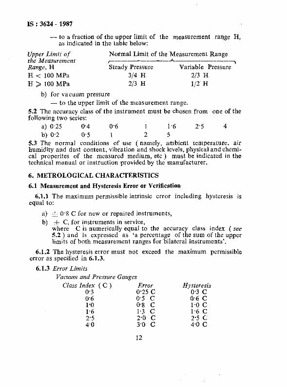
- to a fraction of the upper limit of the measurement Iange H, as indicated in the table below:
Upper Limit of Normal Limit of the Measurement Range the Measurement ~-----_--_~-_-_-_-__- Range, H Steady Pressure Variable Pressure3 H < 100 MPa 314 H 213 H
H > 100 MPa 213 H l/2 H
b) for vacuum pressure - to the upper limit of the measurement range.
5.2 The accuracy class of the instrument must be chosen from one of the following two series:
a) 0.25 0.4 0.6 1 1.6 2.5 4
b) 0.2 0.5 1 2 5 5.3 The normal conditions of use ( namely, ambient temperature, air humidity and dust content, vibration and shock levels, physical and chemi- cal properites of the measured medium, etc ) must be indicated in the technical manual or instruction provided by the manufacturer.
6. METROLOGICAL CHARACTERISTICS
6.1 Measurement and Hysteresis Error or Verification
6.1.1 The maximum permissible intrinsic error including hysteresis is equal to:
a> b)
-& 0.8 C for new or repaired instruments, * C, for instruments in service,
where C is numerically equal to the accuracy class index ( see 5.2 ) and is expressed as ‘a percentage of the sum of the upper limits of both measurement ranges for bilateral instruments’.
6.1.2 The hysteresis error must not exceed the maximum permissible error as specified in 6.1.3.
6.1.3 Error Limits Vacuum and Pressure Gauges
Class Index ( C ) Error Hysteresis 0.3 0.25 C 0.3 c 0.6 0.5 c 0.6 C 1.0 0.8 C 1.0 c 1.6 1.3 c 1.6 C 2.5 2.0 c 2.5 C 4.0 3.0 c 4-O c
12
t IS:3624 - 1987
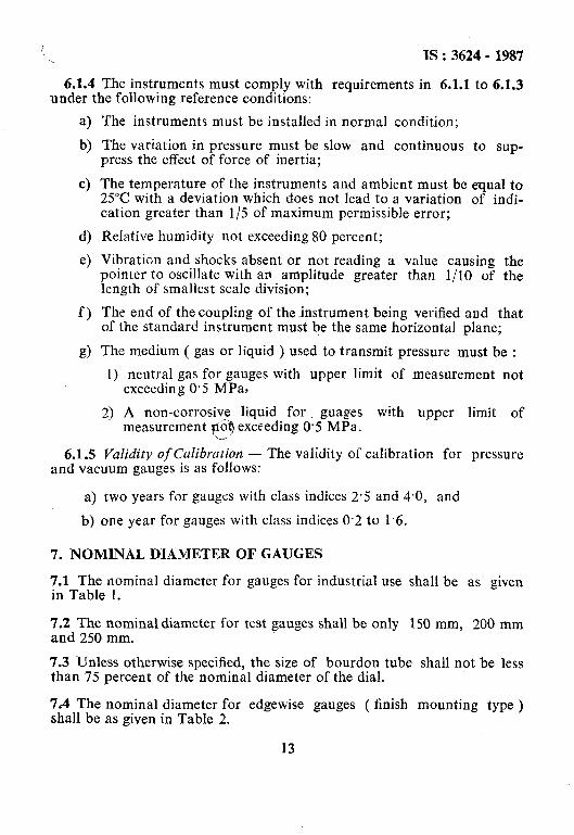
6.1.4 The instruments must comply with requirements in 6.1.1 to 6.1.3 under the following reference conditions:
a) b)
C>
4 e)
f )
g)
6.1.5
The instruments must be installed in normal condition;
The variation in pressure must be slow and continuous to sup- press the effect of force of inertia;
The temperature of the instruments and ambient must be equal to 25°C with a deviation which does not lead to a variation of indi- cation greater than l/5 of maximum permissible error;
Relative humidity not exceeding 80 percent;
Vibration and shocks absent or not reading a value causing the pointer to oscillate with an amplitude greater than l/IO of the length of smallest scale division;
The end of thecoupling of the instrument being verified and that of the standard instrument must be the same horizontal plane;
The medium ( gas or liquid ) used to transmit pressure must be :
1) neutral gas for gauges with upper limit of measurement not exceeding 0.5 MPa,
2) A non-corrosive liquid for. guages with upper limit of measurement ?TQ exceeding 0.5 MPa.
Validity of Culibrazion - The validity of calibration for pressure _ . . and vacuum gauges is as follows:
a) two years for gauges with class indices 2.5 and 4.0, and
b) one year for gauges with class indices 0.2 to 1.6.
7. NOMINAL DIAMETER OF GAUGES
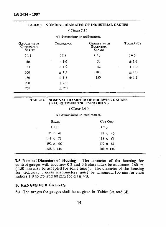
7.1 The nominal diameter for gauges for industrial use shall be as given in Table 1.
7.2 The nominal diameter for test gauges shall be only 150 mm, 200 mm and 250 mm.
7.3 Unless otherwise specified, the size of bourdon tube shall not be less than 75 percent of the nominal diameter of the dial.
7.4 The nominal diameter for edgewise gauges ( finish mounting type > shall be as given in Table 2.
13
IS: 3624 - 1987
TABLE 1
GAUGES WITH CONCENTRIC
SCALES
(1)
50
63
100
150
200
250
NOMINAL DIAMETER OF INDUSTRIAL GAGUES
( Clause 7.1 )
All dimensions in millimetres.
TOLERANCE GAUGES WITH ECCENTRIC
SCALES
(2) (3)
_I 1.0 50
f 1.0 63
f 1.5 100
& 1.5 150
f 2.0
f 2.0
TOLERANCX
(4)
f 1.0
* 1.0
f 1’0
& 1.5
TABLE 2 NOMINAL DIAMETER OF EDGEWISE GAUGES ( FLUSH MOUNTING TYPE ONLY )
( CIause 7.4 )
All dimensions in millimetres.
BEZEL CCJT OUT
(1) (2)
96 x 48 88x 40
144x 72 135 x 64
192 x 96 179 x 87
288 x 144 280 x 136
7;5 Nominal Diameters of Housing - The diameter of the housing for control gauges with accuracy O-3 and 0.6 class index be minimum 160 m ( 150 mm may be accepted for some time ). The diameter of the housing for technical process manometers must be minimum 100 mm for class indices l-0 to 2.5 and 80 mm for class 4-O.
8. RANGES FOR GAUGES
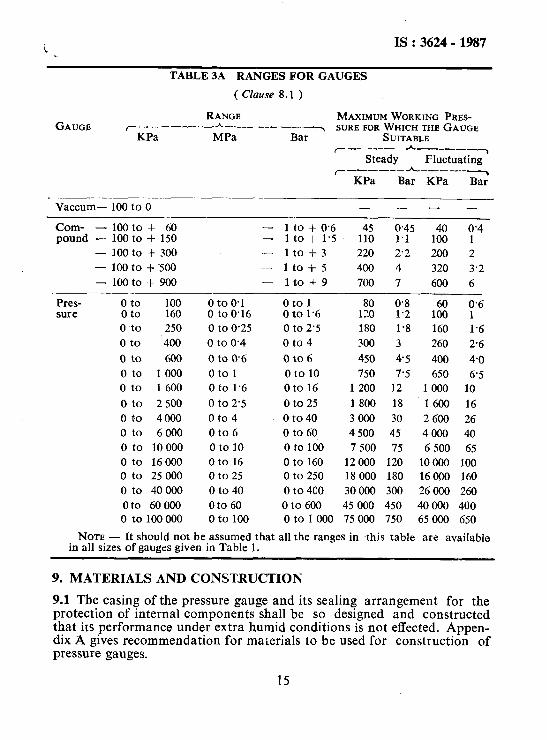
8.1 The ranges for gauges shall be as given in Tables 3A and 3B.
14
i IS:3624-1987
TABLE 3A RANGES FOR GAUGES
(C&se 8.1 )
GAUGE ORANGE MAXIMUM WORKING PRES-
r__ _--__-h-_--__- _--_~ SURE FOR WHICH THE GAUGE KPa MPa Bar SUITABLE
~--_-~-*~____ Steady Fluctuating
~-~_--~_*-~~-~ KPa Bar KPa Bar
Vaccum- 100 to 0 - -- -
Com- - 100 to + 60 - 1 to + 0.6 pound - 100 to + 150 - 1 to + 1.5
1% 0.45 1.1
- 100 to + 300 - 1to+3 220 2.2
- 100 to + 500 - 1to+5 400 4
- 100 to + 900 - 1to+9 700 7
Pres- 0 to 100 0 to 0.1 0 to 1 0.8 sure 0 to 160 0 to 0.16 0 to 1.6 1:: 1.2
0 ~to 250 0 to 0.25 0 to 2’5 180 1.8
*z 0.4 1
200 2
320 3.2
600 6
0.6 1:: 1
160 1.6
0 to 400 0 to 0.4 0 to 4 300 3 260 2.6
0 to 600 0 to 0.6 0 to 6 450 45 400 4.0
oto 1000 0 to 1 0 to 10 750 7.5 650 6.5
0 to 1 600 0 to 1.6 Oto16 1 200 12 1000 10
0 to 2 500 0 to 2.5 0 to 25 1800 18 1600 16
0 to 4000 0 to 4 0 to 40 3 000 30 2 600 26
0 to 6 000 0 to 6 0 to 60 4500 45 4000 40
0 to 10 000 oto10 0 to 100 7 500 75 6 500 65
0 to 16000 Oto 16 0 to 160 12 000 120 10000 100
0 to 25 000 0 to 25 0 to 250 18 000 180 16000 160
0 to 40 000 0 to 40 0 to 400 30000 300 26000 260
0 to 60 000 Oto 60 0 to 600 45 000 450 40000 400 0 to 100 000 0 to 100 0 to 1 000 75 000 750 65 000 650
NOTE - It should not be assumed that all the ranges in this table are available in all sizes of gauges given in Table 1.
9. MATERIALS AND CONST-RUCTION
9.1 The casing of the pressure gauge and its sealing arrangement for the protection of internal components shall be so designed and constructed that its performance under extra humid conditions is not effected. Appen- dix A gives recommendation for materials to be used for construction of pressure gauges.
15
IS:3624 - 1987
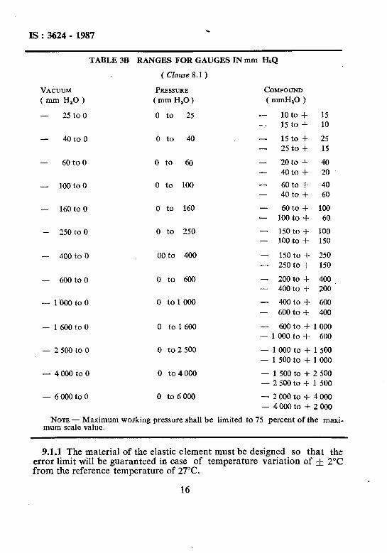
TABLE 3B RANGES FOR GAUGES IN mm HaQ
( CIause 8.1 )
VAouuM PRESSURE COMPOUND
( mm H,O ) (mm&O) ( mmIW )
- 25 to 0 0 to 25 - 10 to + 15 - 15 to + 10
- 40 to 0 0 to 40 - 15 to + 25 - 25to + 15
- 60 to 0 Oto 60 - 20 to + 40 - 40 to + 20
- - 1OOtoo 0 to 100 60 to + 40 - 40 to + 60
- 160 to0 0 to 160 - 60to+ 100 - 100 to + 60
250 to 0 0 to 250 - - 150 to + 100 - loot0 f 150
400 to 0 00 to 400 - - 150 to f 250
- 250 to + 150
- - 600 to0 0 to 600 200 to + 400 - 400 to + 200
- 1OOOtoO 0 to 1000 - 400 to + 600
- 600mto + 400
- - 1 600 to 0 0 to 1600 600 to + 1 000 - 1 000 to + 600
- 25OOtoo 0 to2 500 - 1 000 to + 1 500
- 1500to + 1~000
- 4 000 to 0 0 to4000 - 1 500 to + 2 500 - 2 500 to + 1 500
- 6000to0 0 to 6 000 - 2000 to $ 4000
- 4000to + 2000
NOTE - Maximum working pressure shall be limited to 75 percent of the maxi- mum scale value.
9.1.1 The material of the elastic element must be designed so that the error limit will be guaranteed in case of temperature variation of f 2°C from the reference temperature of 27°C.
16
I IS : 3624 - 1987
9.13 For industrial gauges, the case shall be weather proof to protect the inner components from humidity, liquid splash, dust and corrosion. The degree of protection shall be as per applicable IP Code related to specific environment of use.
9.1.3 Cases may be provided uith baffle wall and blow out devices de- pending on the ~pressure and medium. Blow out devices shall be provid- ed at gas pressures of 2 500 kPa above and liquid pressures of 6 000 kPa and above. For gauges below this range, the provision of blow out device is optional. The blow out aperture shall not be less than 25 mm diameter for gauges of 100 mm nominal size and above, which must be ~disposed in a concentric area with a diameter of 45 mm. For nominal sizes less than 100 mm, the blow disc shall be 20 mm diameter. This blow out device shall be capable of releasing any excess pressure over 30 kPa within the case and also prevent dust and water entering the case. The closure shall not be capable of being pressed in from outside while handling normally.
9.1.4 Gau,ges may have B solid back case or a removable back plate. In gauges with removable back plate, it shall be possible to adjust the gauge with back plate removed.
9.1.5 Appendix B specifies safety precautions relating to industrial pres- sure gauges and Appendix C specifies precautions relating to gauges for use with oxygen and acetylene, respectively.
9.2 Bezel - The bezel shall preferably be of the same material as the case. They may be either screwed type or fixed by screws.
NOTE - Attention is drawn to the fact that the nature of the liquid or gas for which the gauge is required may limit the use of certain materials ( see Appendices A, B and C ).
9.3 Shank and Element Anchorage -. The shank and element anchorage shall be of materials not inferior to that of the element. When copper alloy is used, it shall conform to IS : 6912 - 1985”. Other materials may be used by agreement between the purchaser and the manufacturer.
9.3.1 The shank shall be in one piece with its haxagon ( or square or flats ) and shall also serve the purpose of element anchorage in the case of bourdon tube type gauges. For other types of elements, the element an- chorage may be integral with the shank or connecter! with the shank by a flexible pressure conducting system. The material of the pressure con- ducting system shall not be inferior to the element. The shank and the pressure conducting: system shall have a minimum bore of 3 mm to prevent clogging by dirt. Connection between shank and element anchorage by
*Specification for copper and copper alloy forging stock and forgings (first revision ).
17
IS: 3624- 1987
pressure conducting system shall not be used in the case of bourdon tube type gauges. The shank shall be fixed to the case by at least 2 screws. The use of check nuts for the above purpose shall be as below for the various types of gauges:
Direct mounting - Bottom or back
Flush mounting - Back
Surface mounting - Bottom or back
9.3.2 The screwed connection shall project for a sufficient length to enable the gauge to be fitted without fouling the case, and on surface mounting gauges, the spanner flats on the connectlon shall be placed sufficieritly far from the rear flange to enable a standard spanner to be used.
9.3.3 The pressure connection at the shank shall have taper or parallel threads, the end of the shank shall have a flat seat with a spigot. The edge of the spigot shall be rounded off to prevent it from damaging the connection washer. The face of the seat may be chased with a concentric groove or grooves.
9.4 Pressure Sensing Element - The element shall be manufactured from a material suitable for use with the pressure medium at the pressures required, preferably one of the materials given in Appendix D. A general indication of mechanical properties, in the case of bourdon tubes, is given in Appendix E. The material of the element shall be stated on the dial of the gauge.
NOTE - In the case of gauges for use with fluids which would have a corrosive effect on copper alloy or steel, other materials may be used as agreed to between the purchaser and the manufacturer. The information given in Appendices D and E relate to elements as a material and not in its finished state as bourdon tube, bellows or diaphragm.
9.4.1 The assembly of the element with the anchorage should be care- fully done so as to comply with the test requirements specified in 12.
9.4.2 The joint between the element and anchorage or the element and its end piece and any other joint in the pressure conducting system shall be made by soft soldering, silver brazing or welding according to the medium, pressure/temperature range and the particular application of the gauge. The recommended practice of joining, for various temperatures to which the element joints are subjected to, are given below:
Soft soldered - 30 to 50°C Silver brazed - 30 to 120°C Welded - 30 to temperature above
120°C.
18
IS:3624- 1987 ‘._
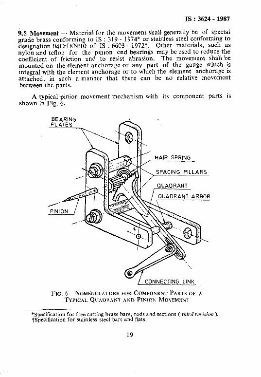
9.5 Movement - Material for the movement shall generally be of special grade brass conforming to IS : 319 - 1974* or stainless steel conforming to designation 04Crl8NilO of IS : 66C3 - 19727. Other materials, such as nylon and teflon for the pinlon end bearings may beused to reduce the coefficient of friction and to resist abrasion. The movement shall be mounted on the element anchorage or any part of the gauge which is integral with the element anchorage or to which the element anchorage is attached, in such a manner that there can be no relative movement between-the parts.
A typical pinion shown in Fig. 6.
movement mechanism with its component parts is
- / CONNECTING LINK
FIG. 6 NOMENCLATURE FOR COMPONENT PARTS OF TYPICAL QUADRANT AND PINION MOVEMENT
*Specification for free cutting brass bars, rods and sections ( third revision ). tspecification for stainless steel bars and flats.
19
IS :3624- 1987
9.6 Dial - The dial shall ‘be made of a suitable metal or of such a plastic material that the finished dial shall be capable of withstanding a dry heat of 85°C for 10 hours, and immersion in water at 85°C for 1 hour without cracking, blistering, wraping or discolouration of the dial or paint on the dial.
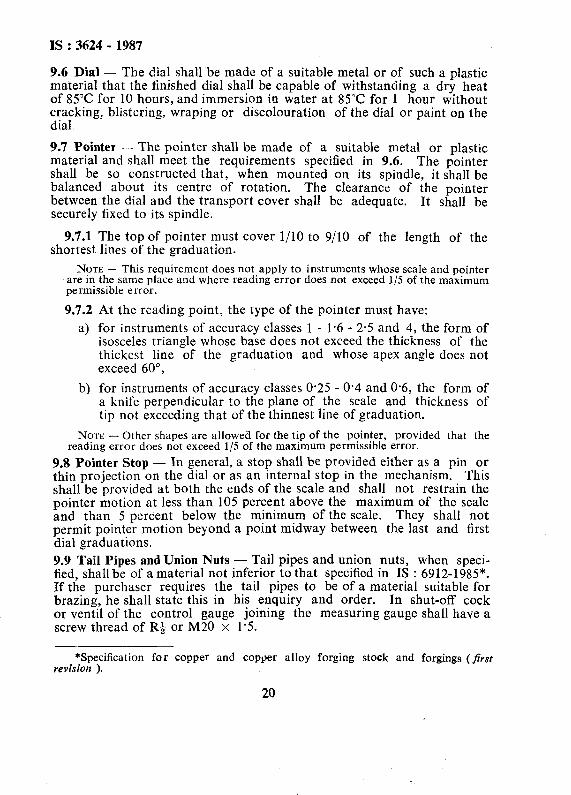
9.7 Pointer - The pointer shall be made of a suitable metal or plastic material and shall meet the requirements specified in 9.6. The pointer shall be so constructed that, when mounted on its spindle, it shall be balanced about its centre of rotation. The clearance of the pointer between the dial and the transport cover shall be adequate. It shall be securely fixed to its spindle.
9.7.1 The top of pointer must cover l/10 to 9/10 of the length of the shortest lines of the graduation.
NOTE - This requirement does not apply to instruments whose scale and pointer are in the same place and where reading error does not exceed l/S of the maximum permissible error.
9.7.2
a>
bl
At the reading point, the type of the pointer must have:
for instruments of accuracy classes 1 - 1.6 - 2.5 and 4, the form of isosceles triangle whose base does not exceed the thickness of the thickest line of the graduation and whose apex angle does not exceed 60”,
for instruments of accuracy classes 0.25 - 0.4 and O-6, the form of a knife perpendicular to the plane of the scale and thickness of tip not exceeding that of the thinnest line of graduation.
NOTE - Other shapes are allowed for the tip of the pointer, provided that the reading error does not exceed l/5 of the maximum permissible error.
9.8 Pointer Stop - In general, a stop shall be provided either as a pin or thin projection on the dial or as an internal stop in the mechanism. This shall be provided at both the ends of the scale and shall not restrain the pointer motion at less than 105 percent above the maximum of the scale and than 5 percent below the minimum of the scale. They shall not permit pointer motion beyond a point midway between the last and first dial graduations. 9.9 Tail Pipes and Union Nuts - Tail pipes and union nuts, when speci- fied, shall be of a material not inferior to that specified in IS : 6912-1985*. If the purchaser requires the tail pipes to be of a material suitable for brazing, he shall state this in his enquiry and order. In shut-off cock or ventil of the control gauge joining the measuring gauge shall have a screw thread of R& or M20 x 15.
*Specification for copper and copper alloy forging stock and forgings (first revision ).
20
IS : 3624 - 1987
NOTE - Brass conforming to IS : 319-1974* or stainless steel grade 04Cr17Ni12 - Mo2 as per IS : 6603 - 1972t is also recommended for the fabrication of wetted parts.
9.10 Window Cover - The transparent cover shall be made of a glass sheet having a thickness of 1.5 to 3 mm but in no case the thickness of glass sheet shall be less than 3 mm for gauges above 100 mm nominal size. It shall be uniform in thickness and free from defects which are likely to im- pair the readability of the gauge. Other transparent material including plastic may be used subject to an agreement between the supplier and the purchaser. But the-material shall meet the-requirements given in 9.6 ( see Appendices B and C ).
9.11 Over-range Protection -- If it can be anticipated that during nor- mal life of a pressure gauge the gauge will be subjected to overpressure, an internal stop or mechanism release shall be provided to protect the pressure element from damage and prevent disengagement of the mechan- ism gearing. Stops should be designed to restrain the pressure element or the mechanism rather than the pointer.
9.12 Zero Adjustment - Gauges of sizes 100 mm and above may be pro- vided with a device for zero adjustment.
10. DIMENSIONS AND TURNING RADIUS
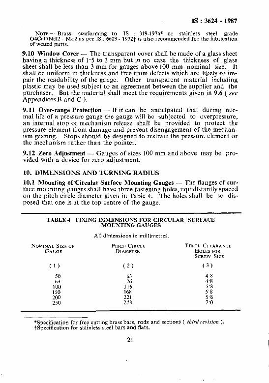
10.2 Mounting ofCircular Surface Mounting Gauges - The flanges of sur- face mounting gauges shall have three fastening holes,~equidistantly spaced on the pitch circle diameter given in Table 4. The holes shall be so dis- posed that one is at the top centre of the gauge.
TABLE 4 FIXING DIMENSIONS FOR CIRCULAR SURFACE MOUNTING GAUGES
All dimensions in millimetres.
NOMINAL SIZEOF PITCH CIRCLE GAUGE DIAMETER
THREE CLEARANCE HOLES FOR SCREW SlZE
(1) (2) (3)
50 4.8
,:?I
:z 4’8
116 5’8 150 168 5.8 200 221 5’8 250 273 7.0
*Specification for free cutting brass bars, rods and sections ( third revision ). tspecification for stainless steel bars and flats.
21 I
IS : 3624 - 1987
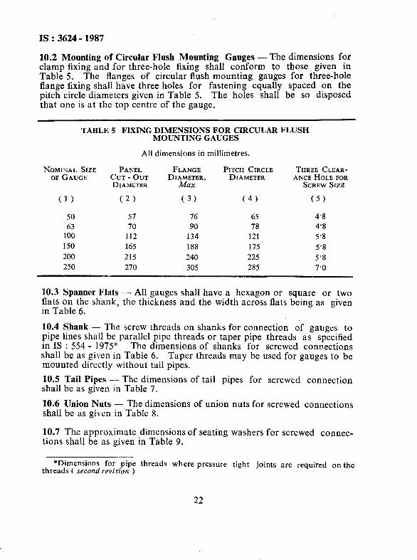
10.2 Mounting of Circular Flush Mounting Gauges - The dimensions for clamp fixing and for three-hole fixing shall conform to those given in Table 5. The flanges of circular flush mounting gauges for three-hole flange fixing shall have three holes for fastening equally spaced on the pitch circle diameters given in Table 5. The holes shall be so disposed that one is at the top centre of the gauge.
TABLE 5 FIXING DIMENSIONS FOR CIRCULAR FLUSH MOUNTING GAUGES
All dimensions in millimetres.
NOMINAL SIZE PANEL FLANGE PITCH CIRCLE THREE CLEAR- OF GAUGE CUT - OUT DIAMETER, DIAMETER ANCE HOLE FOR
DIAMETER Max SCREW SIZE
(1) (2) (3) (4) (5)
50 57 76 65 4.8
63 70 90 78 4’8
100 112 134 121 5’8
150 165 188 175 5’8
200 215 240 225 5’8
250 270 305 285 7’0
10.3 Spanner Flats - All gauges shall have a hexagon or square or two flats on the shank, the thickness and the width across flats being as given in Table 6.
10.4 Shank - The screw threads on shanks for connection of gauges to pipe lines shall be parallel pipe threads or taper pipe threads as specified in IS : 554 - 1975” The dimensions of shanks for screwed connections shall be as given in Table 6. Taper threads may be used for gauges to be mounted directly without tail pipes,
10.5 Tail Pipes -- The dimensions of tail pipes for screwed connection shall be as given in Table 7.
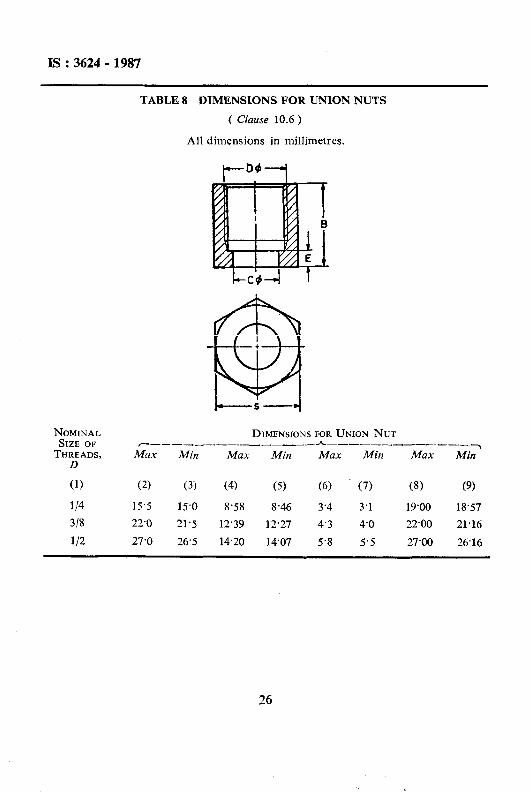
10.6 Union Nuts - The dimensions of union nuts for screwed connections shall be as given in Table 8.
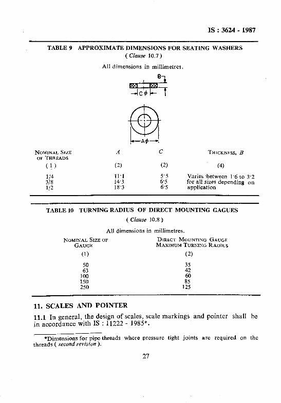
10.7 The approximate dimensions of seating washers for screwed connec- tions shall be as given in Table 9.
*Dimensions for pipe threads where pressure tight joints are required on the threads c second revision )
22
IS :3624- 1987
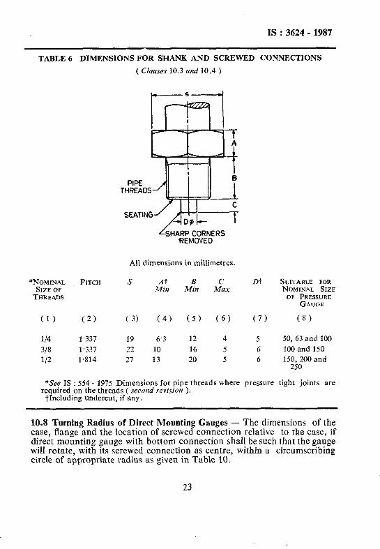
TABLE 6 DIMENSIONS FOR SHANK AND SCREWED CONNECTIONS
( Clauses 10.3 nnd 10.4 )
~HA~F?C$IIENERS \
All dimensions in millimetres.
*NOMINAL PITCH s At B c m SIZE OF .44in Min Max THREADS
(1) (2) ( 3) (4) (5) (6) (7)
l/4 1,337 19 6.3 12 4 5 318 1,337 22 10 16 5 6 l/2 1.814 27 13 20 5 6
SUITABLE FOR NOMINAL SIZE OF PRESSURE
GAUGE
(8)
50,63 and 100
100 and 150 150,200 and
250
*See IS : 554 - 1975 Dimensions for pipe threads where pressure tight joints are required on the threads ( second revision ).
tIncluding undercut, if any.
10.8 Turning Radius of Direct Mounting Gauges - The dimensions of the case, flange and the location of screwed connection relative to the case, if direct mounting gauge with bottom connection shall be such that the gauge will rotate, with its screwed connection as centre, within a circumscribing circle of appropriate radius as given in Table 10.
23 1
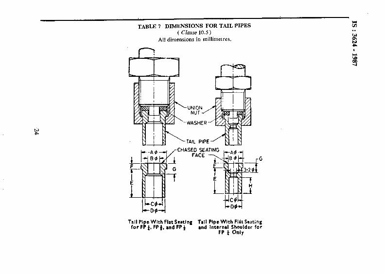
TABLE 7 DIMENSIONS FOR TAIL PIPES ( Clause 10.5 )
All dimensions in millimetres.
XHASEb SE FACE
Tail Pi e With Flat Seating Tail Pipe With Flit Seating for F ! 4, FP j. and FP + and Internal Shbulder for
FP 4 Only

NOMINAL SUITABLE OUTSIDE DIAMETER OF CONNECTING PIPE SIZEOF ~_-~_-_--_--_-----___-_-_ *-_._-_____-__~-_-----_-----~-~ THREADS Max Min MUX Min Max Min Max Min Max Min Max Min Max Min Max Min Max Min
(1) (2) (3) (4) (5) (6) (7) (8) (9) (10) (11) (12) (13) (14) (15) (16) (17) (18) (19)
114 4.83 4’63 11’07 10.95 5.60 5.33 4.98 4.90 8.33 8.20 14.0 13’3 2.4 2.1 4.8 4.1 8.9 8.6
318 9.60 9.45 14.55 14.43 6.60 6’35 9.75 9.68 12’14 12.01 16’0 15’3 3’2 2.9 5’8 5’1 - -
l/2 9’60 9.45 18.20 18.07 7.10 6.85 9.75 9.68 13.95 13.83 16.0 15’3 6.3 2.9; 5’8 5.1 - -
IS : 3624 - 1987
NOMINAL SIZE OF THREADS,
D
DIMENSIONSFOR UNION NUT ~_____-----____-h____-__-----_~
MUX Min Max Min Max Min Max Min
(1) (2) (3) (4) (5) (6) (7) (8) (9)
114 15’5 15.0 8.58 8.46 3’4 3.1 19al 18.57
3/8 22’0 21.5 12.39 12.27 4.3 4.0 22.00 21.16
112 27’0 26.5 14.20 14.07 5.8 5-5 27.00 26.16
TABLE 8 DlMENSIONS FOR UNION NUTS
( Clause 10.6)
All dimensions in millimetres.
I
26
IS: 3624 - 1987
TABLE 9 APPROXIMATE DIMENSIONS FOR SEATING WASHERS
( Cluuse 10.7)
All dimensions in millimetres.
NOMINAL SIZE OF THREADS
( ! 1)
l/4 318 l/2
A
(2)
11.1 14.3 18’3
THICKNESS, B
(4)
Varies between 1.6 to 3.2 for all sizes depending on application
TABLE 10 TURNING RADIIJS OF DIRECT MOUNTING GAGUES
( Clause 10.8 )
All dimensions in millimetres.
NOMINAL SIZE OF DIRECT MOUNTING GAUGE GAUGE MAXIMUM TURNING RADIUS
(1) (2)
:I: :; 100 60 150 250 1%
11. SCALES AND POINTER
11.1 In general, the design of scales, scale markings and pointer shall be in accordance with IS : 11222 - 1985*.
*Dimensions for pipe threads where pressure tight joints are required on the threads ( second revision ).
27
IS : 3624- 1987
11.2 Test gauges shall be provided with knife edge pointer.
11.3 The length of the pointer from the centre line of the pointer shaft to the top of the point for circular dial gauges shall not be less than 40 percent of the nominal size of the gauge.
12. FINISH AND TREATMENT
12.1 The finish and treatment of bezel and case should be anti-corrosive or as agreed between the supplier and the purchaser.
12.2 Protection Against Corrosion - All ferrous parts shall be painted, or otherwise treated to resist corrosion by atmosphere.
12.3 The dial and pointer shall be so finished that they have non-reflec- tive surface.
13. INFORMATION TO BE SUPPL!ED WITH THE ENQUIRY
13.1 The first set of information will always be capable of definition and shall be provided, so that the most suitable gauges conforming to this standard are supplied and shall be AS follows:
a> b)
c> 4 e> f) d h) j)
k)
n-4
Type according to this standard, that is, industrial or test;
Any special requirements additional to this standard;
Range, operating pressure and temperature;
Accuracy;
Nominal size of gauge;
Type of pressure element, that is, bourdon, bellows or diaphragm;
Ma.terial of case;
Connection type, location and size;
Type of mounting - direct, surface or flush;
Capillary length; and
Accessories like tail pipe, syphon, snubbers, dempners, etc.
13.2 The second set of information may not always be equally capable of ready definition, but when those details are given, they will enable the pressure gauges to be selected as may be best suited for the required
28
IS : 3624 - 1987
operating conditions. This set consists of the following:
4
b)
c> d) d
f >
g>
h)
j)
Type of equipment to which the gauge will be fitted:
1) Stationary,
2) Mobile, or
3) Portable.
Any adverse conditions, such as exposure of the gauge to weather, corrosive atmosphere, extreme heat or cold, and high humidity;
Maximum pressure likely to be applied;
Whether pressures will be steady or fluctuating;
Whether subject to :
1) Sudden increase of pressure ( shock loading ); and
2) Sudden decrease of pressure @hock unloading ).
Whether subject to :
I) Mechanical vibration; and
2) Mechanical shock +
Static head;
Name and state of fluid; and
Any other information which may assist in the selection of suit- able gauges.
14. TESTS
_~ 14.1 Accuracy
14.1.1 Test Gauges- Each gauge shall be subjected to a pressure equal to the maximum scale value, and shall be maintained at that pressure for not less than 1 hour. After the pressure is released and without recali-
-%&on or adjustment, the gauge shall be tested over its entire scale, with readings taken both up and down the scale.
The error in pressure indication, with either increasing or decreasing pressure, at any point on the Gale, shall not exceed + 0.25 percent of the maximum scale value at 27°C. . I T r
d ’ 14.1.2 Industrial Concentric/Edgewise Scale Gauge Class IA - Each gauge shall be tested over its entire scale with readings taken both up and
29
IS: 3624- 1987
down the scale. The error in pressure indication with either increasing or decreasing pressure, at any point, shall not exceed one - half of 1 per- cent of the maximum scale value, and for the rest of the scale, 1 percent of the maximum scale value.
14.1.3 Industrial Concentric/Edgewise Scale Gauge Class IB - Each gauge shall be tested over its entire scale, with readings taken both up and down the scale. The error in pressure indication with either increas- ing or decreasing pressure, at any point, shall not exceed one percent of the maximum scale value, and, for the rest of the scale, I+ percent of the maximum -scale value.
14.1.4 Industrial Concentric/Edgewise Scale Gauges Class II - Each gauge shall be tested over its entire scale, with readings taken both up and down the scale. The error in pressure indication with either increasing or decreasing pressure, at any point on the scale, shall not exceed three percent of the maximum scale value.
14.1.5 Industriul Eccentric Scale Gauges - Each gauge shall be tested over its entire scale, with readings taken both up and down the scale. The error in pressure indication with either increasing or decreasing pressure, at any point above 10 percent and below 90 percent of the maximum scale value, shall not exceed two percent of the maximum scale value, and for the rest of the scale, 3 percent of the maximum scale value.
14.1.6 Industrial gauges with bellows, diaphragms or capsules as pres- sure sensing elements shall be tested over its entire scale with readings taken both up and down the scale. The error in pressure indication with either increasing or decreasing pressure, at any point in the scale, shall not exceed 14 percent of the maximum scale value.
NOTE 1 - The specified permissible errors for eccentric scale gauge are larger than those for concentric scale gauges of equal nominal size, since the scale base length is substantially shorter and the error of observation is likely to be greater.
NOTE 2 - Recommendations as to suitable calibration standards for the testing of pressure gauges are given in Appendix F.
NOTE 3 - The gauge may be lightly tapped during testing.
NOTE 4 - The above tests shall be conducted on the gauge at a temperature of 27 f 5°C.
14.2 Test for Influence of Temperature ( Type Test) - This test is applicable for pressure and vacuum ganges of Industrial applications. The instruments shall be tested for variation of error with temperature. The variation of error shall not exceed + O-3 percent of the error of the instrument determined under test in 14.1 for a change of f 10°C in temperature.
30
IS : 3624 - 1987
14.3 Overload Test
14.3.1 The overload test is not applicable to test gauges.
14.3.2 For industrial gauges, the pressure shall be raised steadily to a value representing the overload on the maximum scale value as given in the table below.
Maximum Scale Value MPa
Overload on Maximum Scale Value Percent
Up to and including 15 25
Above 15 up to and including 60 15
Above 60 10
14.3.3 The pressure shall then be released steadily to zero and when the gauge is again tested for accuracy by the procedure laid down in 13.2 or 13.3, it shall not show errors exceeding the specified limits.
14.3.3.1 In the case of eccentric scale gauges, the complete overload test should be applied, if practicable. If impracticable, the pressure shall be increased to the point where the pointer touches the spacer. The procedure specified in 12.3 shall then be carried out.
,,,;_-$/4.4 Shock Test
14.4.1 The gauges shall be subjected to a shock test, shaking with an acceleration of 30 m/s2 and a frequency of 80 to 120 shocks per minute for a period of not less than 2 hours. After this test, the error shall not change by more than f 2 percent of maximum scale value.
14.5 Endurance Test \
\i’ 14.5.1 The gauge shall be subjected to cyclic pressure fluctuations on satisfactory completion of overload and shock tests:
a>
b)
Low psessure gauges with a steady working pressure up to and including 6 MPa shall be subjected to pressure fluctuation of approximately 50 percent of maximum pressure range. It shall be adjusted to lie between 25 to 75 percent of maximum scale reading having a frequency of 60 cycles per minute for a period of 300 hours.
High pressure gauges with a steady working pressure above 6 MPa shall be subjected to pressure fluctuation of approximately 30 percent of maximum pressure range. It shall be adjusted to
31
IS :3624 - 1987
lie between 35 to 65 percent of maximum scale reading having a frequency of 30 cycles per minute for a period of 100 hours.
cl The gauges must be capable of withstanding-a pressure varying in a continuous manner, with a frequency not exceeding 1 Hz between the limits and for a total number of cycles indicated below:
Upper Limit qf the Measurement Range
MPa
Limits of Pressure Variation as Percent o,f the Upper Limit
of the Measurement Range
No. of Cycles
From 0.05 to1 0 included 30 - 70 15 000
From 10 to 60 included 40 - 60 10 000
From 60 to 160 included 40 - 60 5 000
From 160 to 1 000 included 40 - 60 1 000
l4.5.2 The gauge shall be considered to have failed in the above test if pressure element is fatigued and the required 2 percent of maximum scale value.
14.5.2.1 The difference at any point in the range between gauge errors before and after ~endurance test shall not exceed 2 percent of maximum scale value.
15. MARKING
15.1 Scale Marking
15.1.1 The pressure gauges for the whole range, vacuum gauges and in combined pressure and vacuum gauges, the pressure and vacuum scale markings shall normally be black on a white background and should. be a non-reflective surface. However, the vacuum scale markings may also be provided in red, if so desired by the user. When a particular maxi- mum marking pressure or vacuum is to be iadicated, this indication shall take the form of a bold and long red line on the scale.
15.1.2 In pressure gauges and in combined pressure and vacuum gauges, the pointers shall move clockwise for increase of pressure.
15.1.3 The scale markings and layout shall be in accordance with IS : 8525 - 1977”.
*Recommendations for design of linear scales and indexes for indicating instru- ments to be read to 0.33-1’25 percent resolution.
32
IS:3624-1987
15.2 Each gauge shall be legibly and permanently marked with the manufacturer’s name or trade-mark and, in addition, the following particulars:
a> b)
c> 4
Designation of pressure units;
The material of the pressure element;
The words ‘Test Gauge’ if applicable; and
Any other marking shall be kept to a minimum, preferably outside the area swept by the pointer.
15.2.1 The purpose or the function of the gauge should not be marked on the dial, unless it is to identify the pressure medium, that is, oxygen and acetylene ( see Appendix C ).
15.2.2 The gauges may also be marked with the Standard Mark.
NOTE - The use of the Standard Mark is governed by the provisions of the Bureau of Indian Standards Act, 1986 and the rules and regulations made there- under. The Standard Mark on products covered by an Indian Standard conveys the assurance that they have been produced to comply with the requirements of that standard under a well-defined system of inspection, testing and quality control which is devised and supervised by BIS and operated by the producer. Standard marked products are also continuously checked by BIS for conformity to that standard as a further safeguard. Details of conditions under which a licence for the use of the Standard Mark may be granted to manufacturers or producers, may be obtained from the Bureau of Indian Standards.
16. PACKING
16.1 The inlet and screwed connection shall be protected by a suitable cap. Each gauge shall be wrapped individually in a bubbled polythene sheet and packed in a thermocole box. Such boxes shall be packed in a .carton or box, with adequate cushioning material to minimize movement ,of the gauge and to ensure that the gauge is capable of withstanding normal transit risks without damage.
16.2 The gauges shall be transported in packing, which ensures that their metrological characteristics are maintained.
Where it becomes necessary to check the effect of the transport condi- tions, the instruments are subjected to:
a) an ambient air temperature of - 20°C and + 50°C for 6 hours at each of these temperatures, and
b) Subject it to shock test specified in 14.3.
33
IS: 3624 - 1987
APPENDIX A
( Cluuse 9.1 )
RECOMMENDATIONS FOR MATERIAL AND USE OF PRESSURE GAUGES
A-l. GENERAL CONSIDERATIONS
A-l.1 Although gauges may be expected to give a long period of reliable service, if correctly selected, installed and used, the selection of the type of gauge unsuited to the particular application or careless installation may result in inaccurate indication and even early failure of the gauge. Particular care is essential in selecting and installing a gauge which is to operate under adverse working conditions, such as rapidly fluctuating pressure, vibration, excessive heat or cold, or with corrosive or explosive fluids.
A-2. WORKING PRESSURE LIMITS
A-2.1 The maximum working pressure limits are given in Table 2. If these pressures are exceeded repeatedly, the pressure element may take a per- manent set, thus causing error in the pressure indication. In no case, after installation, should a gauge be exposed to a pressure beyond the maximum scale value. It follows that plain vacuum gauges should not be subjected to pressure.
A-3. SEATING WASHERS
A-3.1 Seating washers used in connections should be of a material which will not easily fray or extrude and shall also be compatible with the pressure medium. The use of rubber should be avoided.
For working pressures of 6 MPa and under, the following materials are suitable for seating washers:
a) Compressed asbestos fibre;
b) Rubber-bonded compressed asbestos;
c) Copper asbestos;
d) Teflon; and
e) Neoprene.
34
IS : 3624 - 1987
For working pressure above 6 MPa, it is recommended that one of the following metal washers is used to avoid the possibility of blow- out:
a) Annealed copper, b) Annealed aluminium, or c) Metal-bonded seals.
A-3.2 For examples of correct and incorrect methods of making the con- nections and mounting the pressure gauges, see Fig. 7 to 9.
A-3.3 Information regarding washers for connecting gauges with oxygen or acetylene lines is given at C-l and C-2.
A-4. PRESSURE CONNECTION
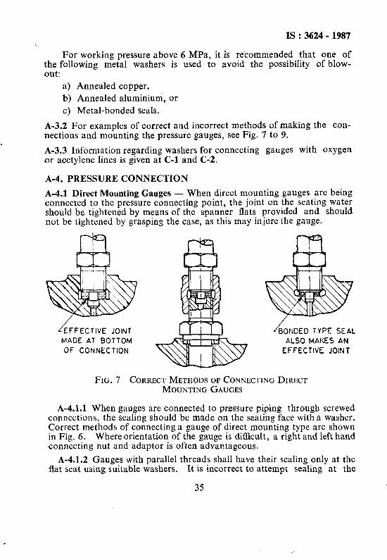
A-4.1 Direct Mounting Gauges - When direct mounting gauges are being connected to the pressure connecting point, the joint on the seating water should be tightened by means of the spanner flats provided and should not be tightened by grasping the case, as this may injure the gauge.
OF CONNECTION
NDED TYPE SEAL ALSO MAKES AN
EFFECTlYE JOINT
FIG. 7 CORRECT METHODS OF CONNECTING DIRECT MCKJNTING GAUGES
A-4.1.1 When gauges are connected to pressure piping through screwed connections, the sealing should be made on the seating face with a washer. Correct methods of connecting a gauge of direct mounting type are shown in Fig. 6. Where orientation of the gauge is difficult, a right and left hand connecting nut and adaptor is often advantageous.
A-4.1.2 Gauges with parallel threads shall have their scaling only at flat seat using suitable washers. It is incorrect to attempt sealing at
35
the the
IS :3624 -1987
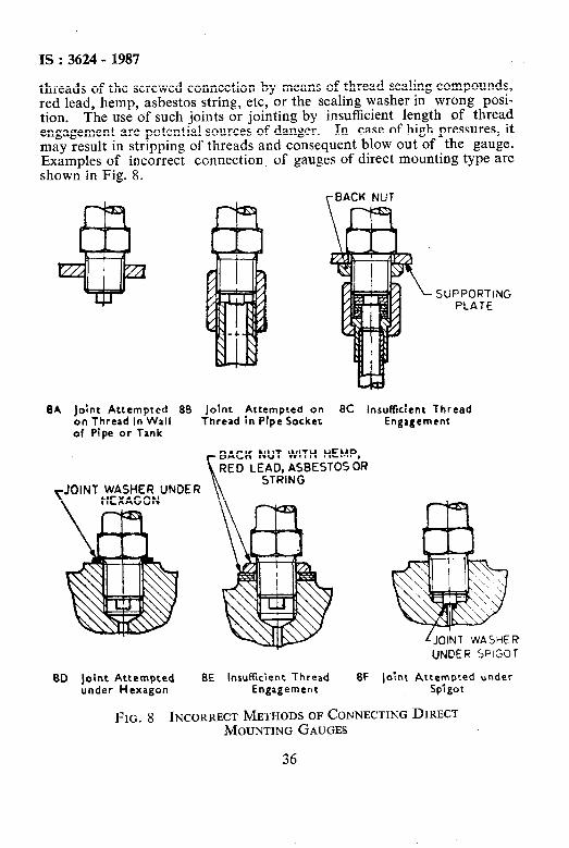
threads of the screwed connection by means of thread sealing compounds, red lead, hemp, asbestos string, etc, or the sealing washer in wrong posi- tion. The use of such joints or jointing by insufficient length of thread engagement are potential sources of danger. In case of high pressures, it may result in stripping of threads and consequent blow out of the gauge. Examples of incorrect connection of gauges of direct mounting type are shown in Fig. 8.
SUPPORTING PLATE
BA joint Attempted 88 Joint Attempted on 8C insufficient Thread on Thread In Wall Thread in Pfpe Sacker of Pipe or Tank
Engagement
JOINT WASHER UNDER \ HEXAGON
BACK NUT WITH HEMP, LE&,A;BESTOS OR
80 joint Attempted 8E Insufftcient Thread 8F under Hexagon Engagement
LJOINT WASHER
UNOER SPIGOT
joint Attempted under Spigot
FIG. 8 INCORRECT’ METHODS OF CONNECTING DIRECT MOUNTING GAUGES
36
IS:3624-1987
A-4.1.3 Gauges with taper threads may be fixed using suitable thread scaling compounds or teflon taper. The use of hemp and other fibres shall be avoided.
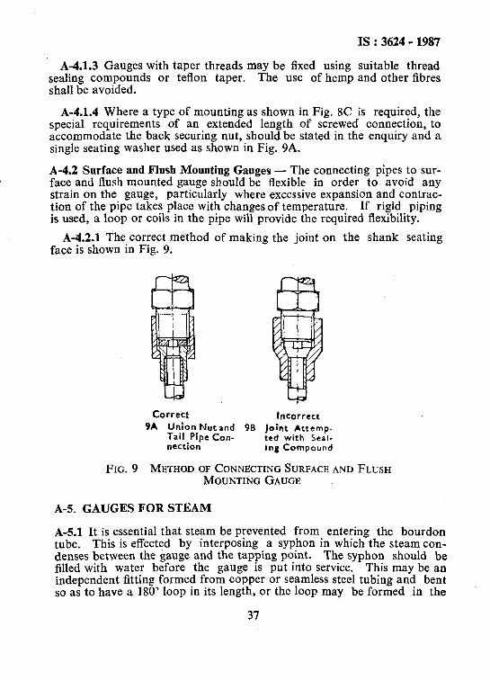
A-4.1.4 Where a type of mounting as shown in Fig. 8C is required, the special requirements of an extended length of screwed connection, to accommodate the back securing nut, should be stated in the enquiry and a single seating washer used as shown in Fig. 9A.
A-4.2 Surface and Flush Mounting Gauges - The connecting pipes to sur- face and flush maunted gauge should be flexible in order to avoid any strain on the gauge, particularly where excessive expansion and contrac- tion of the pipe takes place with changes of temperature. If rigid piping is used, a loop or coils in the pipe will provide the required flexibility.
A-4.2.1 The correct method of making the joint on the shank seating face is shown in Fig. 9.
Corre’ct Incorrect 9A Union Nut and 98 Joint Attemp-
Tail Pfpe Con- led with Seal- nection Ing Compound
FIG. 9 METHOD OF CONNECTING SURFACE AND FLUSH MOUNTING GAUGE
A-5. GAUGES FOR STEAM
A-5.1 It is essential that steam be prevented from entering the bourdon tube. This is effected by interposing a syphon in which the steam con- denses between the gauge and the tapping point. The syphon should be filled with water before the gauge is put into service. This may be an independent fitting formed from copper or seamless steel tubing and bent so as to have a 180’ loop in its length, or the loop may be formed in the
37
IS : 3624 - 1987
run of piping to the gauge. For syphon tubes, a quality equivalent to that specified in IS : 1545 - 1982* or that specified in IS : 1239 ( Part 2 ) - 19697, is recommended.
A-6. TEMPERATURE PROTECTION
A-6.1 Gauges shall not be exposed to excessive heat or cold, since this causes them to indicate the pressures incorrectly. They should be protec- ted from exposure to high temperatures, and not be mounted on hot boiler casings or hot machine parts, and should be placed at some distance from boilers or other sources of heat, When exposed to ftost, bourdon tubes which contain water, are liable to burst.
A-6.2 Gauges for Hot Liquids and Gases - Gauges should be connected to the tapping point by means of a piping which is sufficiently long to keep the gauge and pressure element cold. If a gauge cannot be grasped by hand without discomfort, it is working at too high a temperature.
A-7. POSITION OF GAUGE
A-7.1 Normally, gauges should be installed with the face of the dial in a vertical position and oriented so that the scale shall be symmetrically dis- placed about the vertical centre line of the gauge. In other positions, the weight of the working parts may influence the reading. It is, therefore, necessary to advise the manufacturer, if it is intended to use the gauge in any position other than vertical so that the gauge may be suitably calibrated.
A-7.2 Gagues with a blow-out back should be mounted not less than 20 mm away from a wall, panel or other obstruction.
A-8. -EFFECT OF LIQUID COLUMNS
A-8.1 If static head of liquid is acting on the gauge, allowance should be made for this at the time of calibration of the gauge and the dial of the gauge should be marked to show the allowance. In these cases the manufacturer should be advised by the purchaser.
*Specification for solid drawn copper alloy tubes for condensers and heat ex- changers ( second revision ).
Part $Specification for mild steel tubes, tubulars and other wrought steel 2 Mild steel tubulars and other wrought steel pipe fittings ( third revision ).
fittings:
38
IS : 3624 - 1987
A-9. RAPIDLY FLUCTUATING PRESSURE, SHOCK PRESSURES AND VIBRATION
A-9.1 Gauges cannot be expected to have a normal life if they are used without protection in any of the following conditions:
a) Pressure changing in value very quickly or fluctuating rapidly, for example, more than one cycle per second;
b) Pressure applied or released very quickly so as to produce shock or heating ( often occuring on hydraulic presses and hydraulic tests );
’ c) Pressure oscillating with high frequency, producing a destructive pressure ripple ( often originating in hydraulic pumps and chatter- ing relief valves ); and
d) Mechanical vibration transmitted to the gauge through either the piping or the mounting.
A-9.2 It is possible to provide protection for gauges which have to work in the conditions indicated in A-10.1, but there is no single device or pro- cedure which is effective in every case. In such cases, protective devices, such as throttle screws, pulsation dampeners or gauge savers could be provided to protect and extend the life of the gauge.
A-10. PROTECTION AGAINST MECHANICAL VIBRATION
A-10.1 It is impossible to prescribe protection against mechanical vibra- tion for all conditions. If a machine on which the gauge would normally be mounted vibrates noticeably, it is preferable to mount the gauge with adequately flexible piping on a wall or stanchion nearby.
A-11. SEALING
A-11.1 Type of seals are designed for use with bourdon type pressure instruments on process applications where:
a) the process fluid would normally clog the bourdon tube,
b) materials capable of withstanding corrosive effects of certain fluids are not available as bourdon tube materials, and
c) the process fluid in the bourdon tube might freeze due to changes in ambient temperatures.
A-11.2 The diaphragm materials may be stainless steel, monel, tantalum, hastelloy or any other material to suit the pressure medium.
39
IS : 3624 - 1987
APPENDIX B
( Clause 9.1.5 )
SAFETY PRECAUTIONS RELATING TO INDUSTRIAL PRESSURE GAUGES
B-l. FOR USE WITH HIGH PRESSURE GAS
B.l.l Although there is not necessarily any great risk in the use of gauges for gases at pressure less than 6 MPa, the purchaser should consider the nature of the gas and the installation conditions, and if necessary, order a gauge of the safety pattern. Gauges used for gases and graduated to any maximum scale value exceeding 6 MPa should be of the safety pattern described at B-l .2.
B-l.2 For safety pattern gauges, the case should be of metal and a solid baffle should be interposed between the bourdon tube and the dial, and a suitable blow-out release should be so fitted to the gauge that in the event of an explosion nor fracture of the pressure element of the gauge, the blast willbe away from the front. The hole, enabling the pointer spindle to pass through the solid baffles, should be kept as small as practicable. There the case is of the surface mounting type, that is, with a rear flange case, it is essential that the gauge is mount,ed at least 20 mm away from the wall or panel to allow for the dissipation of the blast between the rear of the case and the surface on which mounted. It is recommended that the gauge manufacturer supplies the gauge fitted with study on the flange or loose distance pieces for this purpose. glass or a clear plastic material.
The window should be of non-splintering
B-1.2.1 The lack of a solid front gauge shall~have an opening or open- ings whose total area is at least 75 percent of the cross-sectional area of the inside of the case surrounding the elastic element. The opening ( s ) shall be closed by a device that will relieve case pressure build up.
B-2. SAFETY CONSIDERATIONS
B-2.1 The pressure sensing element in most gauges is subjected to high internal stresses, and applications exist where the possibility of catastro- phic failure is present. Pressure regulators, chemical scale, pulsations dampers or snubbers, siphons, etc: are available for use in these potentially hazardous systems.
B-2.2 Pressures in excess of full scale pressure ( or vacuum ) should not be applied, unless recommended by the manufacturer.
40
IS : 3624 - 1987
B-2.3 The window material will not provide adequate protection against internal case pressure build-up and can, in fact, be the most hazardous component.
B-2.4 The following systems are considered potentially hazardous and must be carefully evaluated:
a> b)
c) 4 4
f) h) j)
Compressed gas systems,
Oxygen systems,
Systems containing hydrogen or free hydrogen atoms,
Corrosive fluid systems ( gas and liquid ),
Pressure systems containing any explosive or flammable mixture or medium,
Steam systems,
Systems where high overpressure could be accidentally applied,
Systems where interchangeability of gauges could result in hazard- ous internal contamination or where lower pressure gauges could be installed in higher pressure systems,
Systems containing radioactive or toxic fluids, and
m) Systems installed in a hazardous environment.
B-2.5 When gauges are to be used in contact with media having known or uncertain corrosrve effects or known to be radioactive, random or unique destructive phenomena can occur. In such cases the user should always furnish the supplier or manufacturer with information relative to the appli- cation and solicit his advice prior to installation of the gauge.
B-2.6 Fires and explosions within a pressure system can cause pressure element failure with very violent effects, even to the point of completely disintegrating or melting the pressure gauge. Violent effects are also pro- duced when failure occurs due to : ( a ) hydrogen embrittlement, ( b ) con- tamination of a compressed gas, ( c ) formation of acetylides, ( d ) melting of soft solder joints by steam or other heat sources, ( e ) corrosion, ( f ) fatigue, ( g ) the presence of shock, and ( h ) excessive vibration. Nearly any failure in a compressed gas system produces violent effects.
B-2.7 The maximum pressure at which a pressure gauge is continuously operated shall not exceed 75 percent of full scale pressure. The gauge selected should have a full scale pressure of approximately twice the inten- ded operating pressure. This does not apply to retarded or suppressed scale gauges. Contact supplier for recommendations.
41
,
TS:3624 - 1987
B-2.8 The elastic element is gerenerally a thin walled member, that of necessity operates under high stress conditions and must, therefore, be carefully selected for compatibility with the pressure medium being measu- red. None of the common element materials is impervious to every type of chemical attack. The potential for corrosive attack is established by many factors including the concentration, temperature and contamination of the medium. The user should inform the gauge supplier of the installa- tion conditions so that the appropriate element materials can be selected.
B-2.9 Some special applications require the pressure element assembly to have a high degree of leakage integrity. Special arrangements should be made between the manufacturer and the user to assure that the allowable leakage rate is not exceeded.
B-2.10 An effective contamination control programme starts with deter- mining the sensitivity of product to contamination. Because absolute values or limits are difficult to establish, it is common practice to select a level of cleanliness based on judgement and economic considerations.
Cleanliness is determined by the size and quantity of maximum per- missible solid contaminants on significant surfaces and/or by the quantity ( ppm ) discernible in the fluid used to clean such surfaces.
B-2.11 Gauges having high and low electric alarm contacts should be built with intrinsic safe casing when used in hazardous areas. Any spark occurring on the contacts should be of a low strength to avoid explosion in such areas.
APPENDIX C
( Clause 9.1.5 )
PRECAUTIONS RELATING TO GAUGES FOR OXYGEN AND ACETYLENE
C-l. GAUGES FOR USE WITH OXYGEN
USE WITH
C-l.1 Oxygen under pressure forms an explosive mixture with oil or grease, and a serious explosion may result, if the two are brought together. Thin films and slight deposits of oil or grease are particularly susceptible to ignition. It is imperative that extreme care be exercised in the manu- facture and testing of oxygen gauges, and in the subsequent cleaning and
42
IS: 3624- 1987
handling of oxygen gauges and their connections, so that they are kept absolutely free from oil and grease.
C-l.2 When oxygen gauges are tested, oil shall not be allowed to touch or enter the gauge. They should be tested with only dry and clean air on testing equipment used for that purpose alone, and no other gauges should be tested on this equipment to avoid the risk of oil contamination. It should be remembered that factosy air supplies are rarely, if ever, free from oil contamination. After any test, the equipment should be thor- oughly degreased.
C-I.3 It is essential that all gauges for use with oxygen should be of the safety pattern and that they should incorporate all of the feature prescri- bed in Appendix B for gauges for use with high-pressure gas.
C-l.4 Seating washers for oxygen gauges may be of the same materials as those described in A-4. except leather, provided they are free from oil or grease of any description.
C-l.5 It is essential that all gauges for use with oxygen shall have plainly inscribed on the dial in black letters the word ‘Oxygen’ and in red letters the warning ‘Use no oil’.
C-l.6 For oxygen gauges, the connection should be immediately plugged after testing is over to avoid entrance of grease or oil parties.
C-l.7 After the testing is over, the gauge should be thoroughly degreased reagents such as trrchloroethylene or carbon tetrachloride.
C-2 GAUGES FOR USE WITH ACETYLENES
C-2.1 Acetylene in conjunction with copper or silver may form an ex- plosive compound and the use of high copper or silver content alloy for any part of the gauge that may come in contact with the gas should be avoided. Where possible, the bourdon tube and all other parts with which the gas may make contact should be constructed of steel. Where the use of steel is impracticable, a low copper content alloy should be used.
C-2.2 Seating washers for acetylene gauges may be of the same material as those described in A-4 except annealed copper and copper asbestos.
C-2.3 It is essential that all gauges for use with acetylene should be of the safety pattern and incorporate all of the features prescribed in Appendix B for gauges for use with high pressure gas.
C-2.4 It is essential that all gauges for use with acetylene shall have plainly inscribed on the dial in red letters the word ‘Acetylene’.
43
IS:3624 - 1987
APPENDIX D .
( Clause 9.4 )
FERROUS AND NON-FERROUS MATERIALS FOR BOURDON TUBING
D-l. NON-FERROUS MATERIALS
~-1.1 Beryllium Copper Tubing - The chemical composition shall be as under:
Beryllium Not less than 1.70 percent
Not more than l-90 percent Cobalt or nickel or cobalt Not less than O-05 percent
plus nickel Not more than 0.40 percent Total impurities Not more than 0.50 percent
Copper The remainder
D-I.2 Brass Tubing - The chemical composition shall be as under:
Copper Not less than 64.0 percent Not more than 67.0 percent
Iron Not more than 0.10 percent
Lead Not more than 0.10 percent
Total other impurities, ex- Not more than 0.40 percent eluding iron and lead
Zinc The remainder
D-1.3 Nickel - Copper - Aluminium Alloy Tubing - The chemical com- position shall be as under:
Aluminium
Titanium
Copper
Carbon Silicon
Not less than 2.00 percent Not more than 4.00 percent Not less than 0.25 percent
Not more than 1 *OO percent Not less than 27.0 percent Not more than 33.0 percent
Not more than 0.25 percent Not more than 1.00 percent
44
Manganese
Sulphur Iron
Total impurities
Nickel (including cobalt )
Not more than 1.50 percent
Not more than 0.01 percent Not more than 2.00 percent
Not more than 0.2 percent
Not remainder but
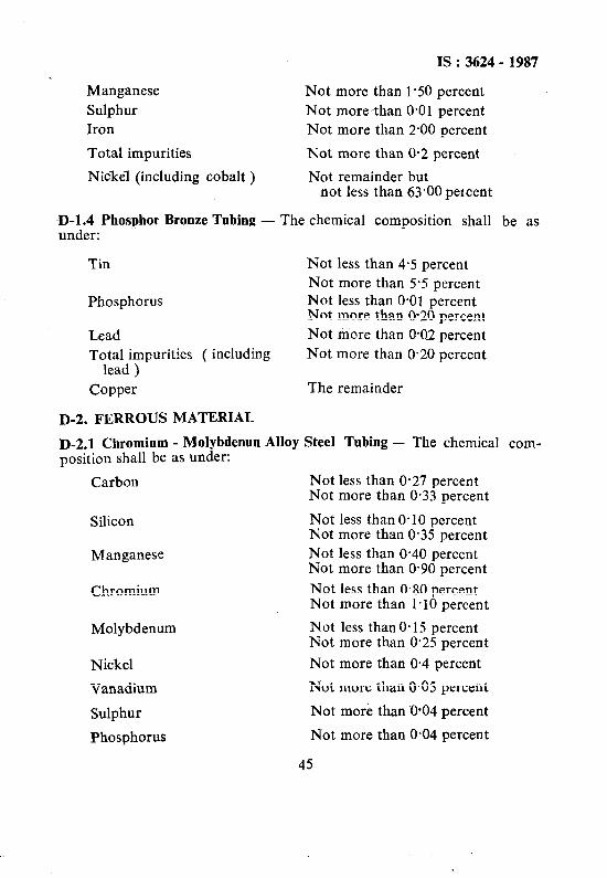
D-1.4 Phosphor Bronze Tubing under:
not less than 63’00 petcent
The chemical composition shall be as
Tin
Phosphorus
Lead
Not less than 4.5 percent Not more than 5-S percent Not less than 0.01 percent Not more than O20 percent Not more than 0.02 percent
Total impurities ( including Not more than 0.20 percent lead )
Copper The remainder
D-2. FERROUS MATERIAL
D-2.1 Chromium - Molybdenun Alloy Steel Tubing - The chemical com- position shall be as under:
Carbon Not less than 0.27 -percent Not more than 0.33 percent
Silicon Not less than 0.10 percent Not more than 0.35 percent
Manganese Not less than 0.40 percent Not more than 0.90 percent
Chromium Not less than 0.80 percent Not more than 1.10 percent
Molybdenum Not less than 0.15 percent Not more than 0.25 percent
Nickel Not more than 0.4 percent
Vanadium Not more than 0.05 percent
Sulphur Not more than OO4 percent
Phosphorus Not more than 0.04 percent
45
IS: 3624- 1987
IS : 3624 - 1987
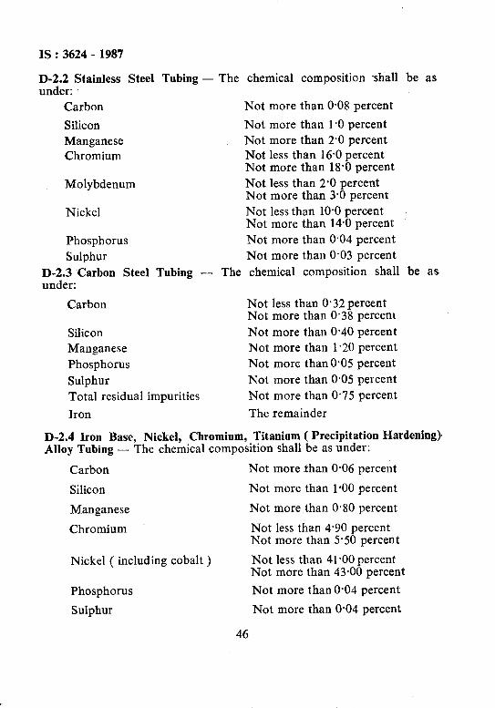
c;$et Stainless Steel Tubing
Carbon
Sihcon Manganese Chromium
Molybdenum
Nickel
Phosphorus Sulphur
D-De: Carbon Steel Tubing
Carbon
Silicon Manganese
Phosphorus
Sulphur Total residual impurities
Iron
- The
- The
chemical composition shall
Not more than O-08 percent
Not more than 1 *O percent Not more than 2.0 percent Not less than 16.0 percent Not more than 18’0 percent Not less than 2’0 percent Not more than 3.0 percent Not less than 10-O percent Not more than 14.0 percent Not more than 0,04 percent Not more than 0.03 percent chemical composition shall
Not less than 0*32percent Not more than 0.38 percem
Not more than 0.40 percent Not more than 1.20 percent Not more than0.05 percent
Not more than 0.05 percent Not more than 0.75 percent
The remainder
be as
be as
D-2.4 Iron Base, Nickel, Chromium, Titanium ( Precipitation Hardening) Alloy Tubing - The chemical composition shall be as under:
Carbon Not more than 0.06 percent
Silicon Not more than 1.00 percent
Manganese Not more than 0.80 percent
Chromium Not less than 4.90 percent Not more than 5.50 percent
Nickel ( including cobalt ) Not less than 41.00 percent Not more than 43.00 percent
Phosphorus Not more than 0.04 percent
Sulphur Not more than 0.04 percent
46

IS : 3624 - 1987
\. Aluminium
Titanium
Total impurities
Iron
Not less than 0.30 percent Not more than 0.80 percent
Not less than 2.10 percent Not more than 2.60 percent
Not more than 0.2 percent
The remainder.
APPENDIX E
( Clause 9.4 )
MECHANICAL PROPERTIES OF COLD DRAWN BOURDON TUBING
The mechanical properties given below provide a general indication of the properties of the tubing used for the fabrication of bourdon tubes. Apart from the hardness values, they do not constitute a mandatory part of the Standard:
Material Condition Tensile Elonga-
s2Pngth tion
cc Percent in 50 mm
*Beryllium copper
*Beryllium copper
W 463 - 540 35 - 45
W(1/4H) 618-772 10-25
Brass ( l/4 H ) 340 - 432 5 -20
*Nickel-copper- W 618 - 757 25 - 40 aluminium alloy
*Nickel-copper- W ( l/4 H ) 695 - 834 15 - 30 aluminium alloy
Phosphor bronze ( i/4 H ) 340 - 432 15 -35 Chromium- Annealed 463 - 556 30 - 40
molybdenum steel
Hard- ness HV
Modulus of El,asas2ty
85 - 120 124 - 131
120 - 185 124 - 131
100 - 140 103
190 Max 158 - 179
250 Max 158 - 179
110 - 140 110 165 MUX 196
47
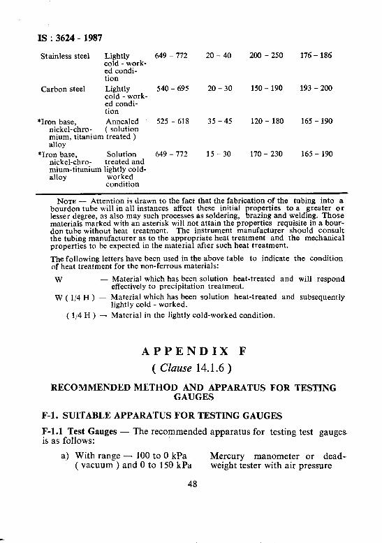
IS : 3624 - 1987
Stainless steel Lightly 649 - 772 cold - work- ed condi- tion
Carbon steel Lightly 540 - 695 cold - work- ed condi- tion
*Iron base, Annealed 525 - 618 nickel-chro- ( solution mium, titanium treated ) alloy
*Iron base, Solution 649 - 172 nickel-chro- treated and mium-titanium lightly cold- alloy worked
condition
20 - 40
20 - 30
35 - 45
15-30
200 - 250
150 - 190
120 - 180
170 - 230
176 - 186
193 - 200
165 - 190
165 - 190
NOTE - Attention is drawn to the fact that the fabrication of the tubing into a bourdon tube will in all instances affect these initial properties to a greater or lesser degree, as also may such processes as soldering, brazing and welding. Those materials marked with an asterisk will not attain the properties requisite in a bour- don tube without heat treatment. The instrument manufacturer should consult the tubing manufacturer as to the appropriate heat treatment and the mechanical properties to be expected in the material after such heat treatment.
The following letters have been used in the above table to indicate the condition of heat treatment for the non-ferrous materials:
W -
W(1/4H) -
Material which has been solution heat-treated and will respond effectively to precipitation treatment.
Material which has been solution heat-treated and subsequently lightly cold - worked.
( 114 H I - Material in the lightly cold-worked condition.
APPENDIX F
( Clause 14.1.6)
RECOMMENDED METHOD AND APPARATUS FOR TESTING GAUGES
F-l. SUITABLE APPARATUS FOR TESTING GAUGES
F-l.1 Test Gauges - The recommended is as follows:
a) With range - 100 to 0 kPa ( vacuum ) and 0 to 150 kPa
48
apparatus for testing test gauges.
Mercury manometer or dead- weight tester with air pressure

IS : 3624 - 1987
b) Maximum scale value above 150 kPa
Dead - weight tester
F-1.2 Industrial Gauges - The recommended apparatus for testing indus- trial gauges is as follows:
a) With range - 100 to 0 kPa Mercury manometer with air ( vacuum ) pressure test gauge as specified
b) Maximum scale value 100 in F-4 ( Dead-weight tester or to 600 kPa mercury coloumn may be used
by agreement between the pur- chaser and the manufacturer )
c) Maximum scale value above Test gauge as specified in F-4 600 kPa or dead-weight tester.
F-2. DEAD-WEIGHT TESTERS
F-2.1 The accuracy of a dead-weight tester depends principally upon the correctness of the piston area, the accuracy of the weights, and the character of the fit between the piston and the cylinder. With a properly constructed instrument, the pressure computed from the piston area and the weights may be assumed to be correct to within one-tenth of 1 per- cent. When greater accuracy is desired, it is recommended to compare the tester directly with mercury manometer.
F-3. MERCURY MANOMETERS
F-3.1 The calibration of the mercury manometer consists essentially of:
a>
b)
c>
checking the accuracy of the manometer scale against a standard of length, making allowance for the fall of mercury in the reser- voir;
determining, if the manometer scale correctly indicates the differ- ence in height~between the two mercury columns over the entire range of the manometer; and
applying the necessary temperature corrections to the value used for the density of the mercury. It is recommended that the glass tubing used be of an internal diameter of not less than 9.5 mm. In using the manometer, precautions should be taken to avoid errors in reading arising from parallax.
F-4. TEST GAUGES USED AS TEST STANDARDS
F-4.1 Test gauges used as test standards should meet the accuracy require- ments specified in 13.1. Test gauges should be calibrated by comparison
49
IS: 3624-1987
with the same test standards as specified in F-1.1. In addition, each test gauge should meet the following special requirements.
F-4.1.1 The maximum scale of the test gauge should be such that it is neither less than that of the gauge to be tested by comparison witb it, nor more than twice the maximum scale value of the gauge to be tested. F-4.2 The test gauge shall be equipped with a device or devices to mini- mize parallax reading errors.
F-4.3 The nominal size of the test gauge shall not be smaller than 150 mm.
F-4.4 The range of the test gauge shall not be less than that of the gauge being calibrated nor more than twice that of the gauge being calibrated.
F-4.5 The test gauge shall not have a stop pin unless it is located below the true zero pressure point of the graduated scale.
F-4.6 The test gauge shall be tested before and after a period of use. The frequency of recalibration will depend on the ability of the gauge to re- tain its accuracy during use. The indicating error for each cardinal point and the date of last calibration shall be noted prominently on the front of the gauge.
F-5. TEST PROCEDURES
F-5.1 The following procedures are suggested when testing a pressure gauge for the operating parameters such as range, span, hysteresis, linearity, calibration, etc, and determining its compliance with the accuracy grades mentioned in 12.
F-5.1.1 Reference Temperature - A temperature of 27 rt: 5°C shall be the reference standard for testing ‘till gauges. All gauges other than temperature compensated gauges shall be tested at the reference temperature. Temperature compensated gauges shall be tested at several ambient temperatures within the range specified by the manufacturer.
NOTE - Gauges represented as being compensated for service at various tem- peratures include those having components of special materials to compensate for the effects of temperatures on Young’s modulus and thermal expansion. The ~magnitude of the greatest error when tested over the entire temperature range specified for the gauge shall determine the accuracy classification of the gauge.
F-5.2 Liquid Head - In calibrating a gauge using a deadweight tester filled with a liquid, the elevation at the bottom of the piston shall corres- pond exactly with a reference level on the gauge. This level shall be at a point where its neutral neutralises the effect of head and weight of the liquid in the system.
50
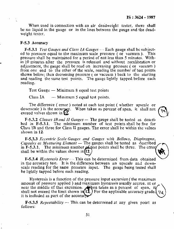
IS : 3624 - 1987
When used in connection with an air deadweight tester, there shall be no liquid in the gauge or in the lines between the gauge and the dead- weight tester.
F-5.3 Accuracy
F-5.3.1 Test Gauges and Class IA Gauges - Each gauge shall be subject- ed to pressure equal to the maximum scale pressure ( or vacuum ). This pressure shall be maintained for a period of not less than 5 minutes. With- in 10 minutes after the pressure is released and without recalibration or adjustment, the gauge shall be read on increasing pressure ( or vacuum ) from one end to the other of the scale, reading the number of test points shown below; then decreasing pressure ( or vacuum ) back to the starting and reading the same test points. The gauge lightly tapped before each reading.
Test Gauge - Minimum 8 equal test points
Class IA - Minimum 5 equal test points.
The difference ( error) noted at each test point ( whether upscale or downscale ) is the accur . When taken as percent of span, it shall not exceed valves shown in t!! cli
\.
F-5.3.2 Classes ZBand II Gauges - The gauge shall be tested as descri- bed in F-5.3.1. The minimum number of test points shall be five for Class IB and three for Class II gauges. The error shall be within the values shown in 12.
F-5.3.3 Eccentric Scale Gauges and Gauges with Bellows, Diaphragms, Capsules as Measuring Element - The gauges shall be tested as described in F-5.3.1. The minimum number est points shall be three. The error shall be within the values shown in 12.
0 UPC
F-5.3.4 Hysteresis Error - This can be determined from data 0 obtained in the accuracy test. It is the difference between fan upscale and down- scale reading for the same pressure input. The gauge being tested shall be lightly tapped before each reading.
Hysteresis is a function of the pressure input excursion ( the maximum amount of pressure applied ) and maximum hysteresis usually accrue. at or near the middle of that excursion.
Q
en taken as a percent of span, i shall not exceed the limit shown i 1 it is included as part of the accurac
For the applicable accuracy grade, \Q 0
F-5.3.5 Repeatability - This can be determined at any given point as follows:
51
Is : 3624 - 1987
Raise or lower the pressure to the desired value as noted on the test standard. Lightly tap the gauge under test and read the pointer. Return the pressure to the original value and repeat the procedure.
The difference between the two pointer readings taken as a percent of span is the repeatability. This does not include hysteresis or friction error. *
52