Embed Size (px)
Citation preview
M064-ZA360-002
Before insta l l ing and using the camera, please read this manual carefully. Be sure to keep it handy for later reference.
About this manual
OPERATION MANUAL
360X AUTO FOCUS ZOOM COLOUR CAMERA
CONTENTS
1. Cautions2. Precautions3. Features4. Components and Accessories • Package • Tr ipod Mount ing
5. Dimensions6. Overview • Rear View
7. Instal lat ion • Connect ing to Monitor • Connect ing to Power • Connect ing to Connect ion
8. Operating Camera • OSD Menu Conf igurat ion • On Screen Display(OSD) • Menu Setup - LENS - EXPOSURE - WHITE BALANCE - WDR(*)/BLC - DAY & NIGHT - IMAGE - SPECIAL _ TITLE _ PRIVACY _ DISPLAY _ MOTION DETECT
9. Communication Protocol10. Specif ications
3
(*) CAUTION : The WDR is an Optional function
1.Cautions
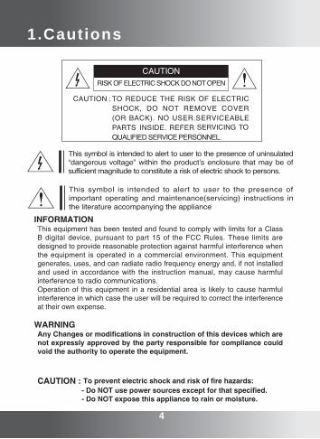
INFORMATIONThis equipment has been tested and found to comply with limits for a Class B digital device, pursuant to part 15 of the FCC Rules. These limits are designed to provide reasonable protection against harmful interference when the equipment is operated in a commercial environment. This equipment generates, uses, and can radiate radio frequency energy and, if not installed and used in accordance with the instruction manual, may cause harmful interference to radio communications.Operation of this equipment in a residential area is likely to cause harmful interference in which case the user will be required to correct the interference at their own expense.
WARNINGAny Changes or modifications in construction of this devices which are not expressly approved by the party responsible for compliance could void the authority to operate the equipment.
CAUTION : To prevent electric shock and risk of fire hazards: - Do NOT use power sources except for that specified. - Do NOT expose this appliance to rain or moisture.
4

Correct Disposal of This Product(Waste Electrical & Electronic Equipment)
(Applicable in the European Union and other European countries with separate collection systems)
This marking shown on the product or its literature, indicate that it should not be disposed with other household wastes at the end of its working life. To prevent possible harm to the environment or human health from uncontrolled waste disposal, please separate this from other types of wastes and recycle it responsibly to promote the sustainable reuse of material resources.
This product should not be mixed with other commercial wastes purchased this product, or their local government office, for details of where and how they can take item for environmentally safe recycling.
Business users should contact their supplier and check the terms and conditions of the purchase contract.Household users should contact either the retailer where they for disposal.
1. A regulated DC12V 500mA power supply is recommended for use with this camera for the best picture and the most stable operation. An unregulated power supply can cause damage to the camera. When unregulated power supply is applied, product warranty will be out of subject.2. It is recommended that the camera is used with a monitor that has a CCTV quality 75 video impedance level. If your monitor is switched to high impedance then please adjust accordingly.3. Do not attempt to disassemble the camera to gain access to the internal components. Refer servicing to your dealer.4. Never face the camera towards the sun or any bright or reflective light, which may cause smear on the picture and possible damage to the CCD.5. Do not remove the serial sticker for the warranty service.
NOTE
1.Cautions
5
CAUTIONS12.Precautions
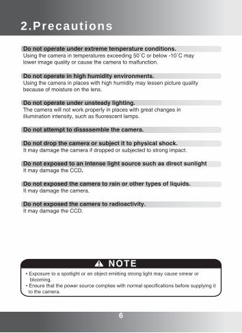
• Exposure to a spotlight or an object emitting strong light may cause smear or blooming.• Ensure that the power source complies with normal specifications before supplying it to the camera.
NOTE
6 7
Do not operate under extreme temperature conditions.Using the camera in temperatures exceeding 50˚C or below -10˚C maylower image quality or cause the camera to malfunction.
Do not operate in high humidity environments.Using the camera in places with high humidity may lessen picture qualitybecause of moisture on the lens.
Do not operate under unsteady lighting.The camera will not work properly in places with great changes in illumination intensity, such as fluorescent lamps.
Do not attempt to disassemble the camera.
Do not drop the camera or subject it to physical shock.It may damage the camera if dropped or subjected to strong impact.
Do not exposed to an intense light source such as direct sunlightIt may damage the CCD.
Do not exposed the camera to rain or other types of liquids.It may damage the camera.
Do not exposed the camera to radioactivity.It may damage the CCD.
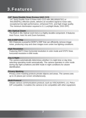
1/4” Sony Double Scan Exview HAD CCD 1/4” Sony Double Scan EXview HAD CCD with 380,000(NTSC) or 440,000(PAL) effective pixels, delivers an excellent signal-to-noise ratio, exceptional low-light performance, enhanced FOV, and high image quality. The minimum illumination required is 0.1 Lux(Night Mode, DSS OFF)
36x Optical Zoom The Built-in 36x Optical zoom lens is a highly durable component. It features Auto Focus, Auto Iris and Zoom functions.
SS-3 DSP Chip SS-3 features a powerful SONY's DSP that can efficiently remove image noise, producing crisp and clear images even under low lighting conditions.
High Resolution Featuring 550TV lines horizontal resolution in color mode and 570TV lines horizontal resolution in BW mode.
Day & Night The camera automatically determines whether it is night time or day time, selecting operating mode automatically. The camera operates in color mode during day light conditions and BW mode in night conditions for clearer identification.
Privacy Masking Privacy Zone masking protects private objects and areas. The camera sets up to 15 places per screen simultaneously.
Multi-Protocol Adopts various communications protocol, such as VISCA(SONY), LG, Pelco- D/P compatible. It enables the camera to be compatible with other equipment.
3.Features
6 7
FEATURES2 CAUTIONS14.Components and Accessories
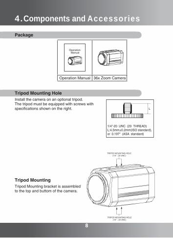
Package
8 9
Operation Manual 36x Zoom Camera
Operation Manual
Tripod MountingTripod Mounting bracket is assembledto the top and buttom of the camera.
Tripod Mounting HoleInstall the camera on an optional tripod.The tripod must be equipped with screws with specifications shown on the right.
8 9
5.Dimensions
6.Overview
10 11
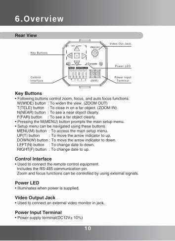
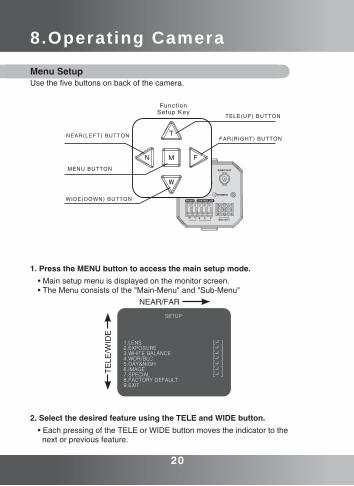
Key Buttons• Following buttons control zoom, focus, and auto focus functions. W(WIDE) button : To widen the view. (ZOOM OUT) T(TELE) button : To close in on a far object. (ZOOM IN) N(NEAR) button : To see a near object clearly. F(FAR) button : To see a far object clearly.• Pressing the M(MENU) button prompts the main setup menu.• Setup menu can be navigated using these buttons. MENU(M) button : To access the main setup menu. UP(T) button : To move the arrow indicator to up. DOWN(W) button : To move the arrow indicator to down. LEFT(N) button : To change date to down. RIGHT(F) button : To change date to up.
Control Interface• Used to connect the remote control equipment. Includes the RS-485 communication pin. Zoom and focus functions can be controlled by using external signals.
Power LED• Illuminates when power is supplied.
Video Output Jack• Used to connect an external video monitor in jack.
Power Input Terminal• Power supply terminal(DC12V± 10%)
Video Out Jack
Power LED
Power InputTerminal
Control Interface
Key Buttons
Rear View
7.Instal lat ion
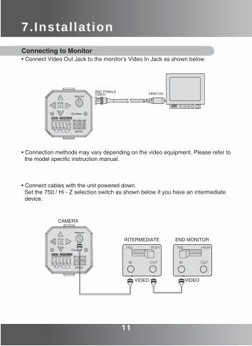
Connecting to Monitor• Connect Video Out Jack to the monitor's Video In Jack as shown below.
• Connection methods may vary depending on the video equipment. Please refer to the model specific instruction manual.
• Connect cables with the unit powered down. Set the 75Ω / Hi - Z selection switch as shown below if you have an intermediate device.
10 11
CAMERA
INTERMEDIATE END MONITOR
VIDEO VIDEO
7.Instal lat ion
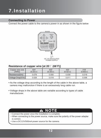
• Connect the power once the installation is complete.• When connecting to the power source, make sure the polarity of the power adapter is correct. • Use a DC12V/500mA power source for the camera.
NOTE
Connecting to PowerConnect the power cable to the camera's power in as shown in the figure below
• As the voltage drop according to the length of the cable in the above table, a camera may malfunction if there is an excessively long cable run.
• Voltage drops in the above table are variable according to types of cable manufacturer.
Resistance of copper wire [at 20℃ (68˚F)]Copper wire size
(AWG) #24
(0.22㎟)#22
(0.33㎟)#20
(0.52㎟)#18
(0.83㎟)
Resistance(Ω/m) 0.078 0.050 0.030 0.018
Voltage Drop(V/m) 0.028 0.018 0.011 0.006
12 13
7.Instal lat ion
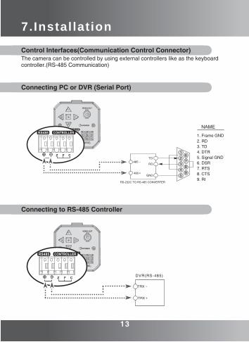
Control Interfaces(Communication Control Connector)The camera can be controlled by using external controllers like as the keyboard controller.(RS-485 Communication)
Connecting PC or DVR (Serial Port)
Connecting to RS-485 Controller
12 13
RS-232C TO RS-485 CONVERTER
7.Instal lat ion
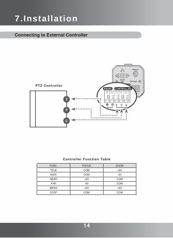
Connecting to External Controller
FUNC. FOCUS ZOOM
TELE COM +6V
WIDE COM -6V
NEAR +6V COM
FAR -6V COM
MENU +6V +6V
STOP COM COM
Controller Function Table
14 15
7.Instal lat ion
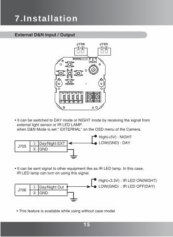
External D&N Input / Output
• It can be switched to DAY mode or NIGHT mode by receiving the signal from external light sensor or IR LED LAMP. when D&N Mode is set " EXTERNAL" on the OSD menu of the Camera.
• It can be sent signal to other equipment like as IR LED lamp. In this case, IR LED lamp can turn on using this signal.
J705① Day/Night EXT② GND
J706① Day/Night Out② GND
• This feature is available while using without case model.
14 15
High(+5V) : NIGHTLOW(GND) : DAY
High(+3.3V) : IR LED ON(NIGHT)LOW(GND) : IR LED OFF(DAY)
8.Operating Camera
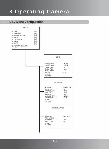
SETUP
1.LENS [┛] 2.EXPOSURE [┛] 3.WHITE BALANCE [┛] 4.WDR/BLC [┛] 5.DAY&NIGHT [┛] 6.IMAGE [┛] 7.SPECIAL [┛] 8.FACTORY DEFAULT 9.EXIT
LENS FOCUS MODE ... AUTOFOCUS LIMIT ... 50CMZOOM START ... x1ZOOM STOP ... x360ZOOM SPEED ... 15E-ZOOM ... ONINITIALRETURN
EXPOSURE
AE MODE ... SHUT FIX BRIGHTNESS ... 8 FLICKERLESS ... OFF SHUTTER ... 1/60 AGC LEVEL ... AUTO MAX AGC GAIN ... 29dB MAX FIELDS ... 128 INITIAL RETURN
WHITE BALANCE WB MODE ... MANUAL WB CONTROL ... - RED CONT ... 30 BLUE CONT ... 50 INITIAL RETURN
OSD Menu Configuration
16 17
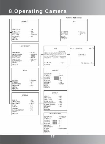
WDR/BLC WDR MODE ... ONWDR LEVEL ... 08BLC MODE ... OFFBLC ZONE ... CENTERBLC LEVEL ... 04INITIALRETURN
DAY & NIGHT
D&N MODE ... AUTO DETECT MODE ... SENSOR DWELL TIME ... 5 SEC D->N LEVEL ... 8 LUX N->D LEVEL ... 100 LUX BURST(NIGHT) ... OFF INITIAL RETURN
IMAGE
ROTATE ... NORMAL FREEZE ... OFF SHARPNESS ... 10 NEGATIVE ... OFF INITIAL RETURN
SPECIAL
CAM ID ... 001 LANGUAGE ... ENG BAUDRATE ... 9600 TITLE ... [┛] PRIVAC ... [┛] DISPLAY ... [┛] MOTION DETECT ... [┛] INITIAL RETURN
TITLE ↓ __________ [M]select ABCDEFGHIJKLMNOPQRSTUVWXYZ abcdefghi jk lmnopqrstuvwxyz 0123456789ÄÖÜÈÆäöüáéíñóúßæ SPACE>> <<BACK MORE>>
LOCATION ... [┛] RETURN
PRIVACY
ZONE NUM. ... 3 CONTROL ... MASK H START ... 10 V START ... 30 H WIDTH ... 200 V HEIGHT ... 110 COLOR ... BLACK INITIAL RETURN
DISPLAY
CAM ID ... ONCAM TITLE ... ONCAM STATE ... ONZOOM RATIO ... ONMOTION DETECT ... OFFPOWER ON MSG. ... ONSTANDBY ... ONINITIALRETURN
MOTION DETECT
ZONE NAME ... WINDOW0 CONTROL ... ON H START ... 4 V START ... 2 H WIDTH ... 4 V HEIGHT ... 4 SENSITIVITY ... 8 ALARM ... OSD&COM INITIAL RETURN
[TITLE LOCATION] [M] [┛]
CAM TITLE
[T]↑ [W]↓ [N]←[F]→
8.Operating Camera
16 17
Without WDR Model BLC
BLC MODE ... OFFBLC ZONE ... CENTERBLC LEVEL ... 04INITIALRETURN
8.Operating Camera
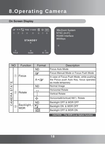
On Screen Display
NO Function Format Description
① Focus
ND Focus Auto Mode
Focus Manual Mode or Focus Push Mode
A • In case of Focus Push Mode, while pushing the Pocus push Auto Key, focus operates as mode temporary
② Rotate
ND Normal Image
Horizontal Rotate
Vertical Rotate
Horizontal&Vertical(180°) Rotate
③Backlight / WDR
ND Backlight OFF & WDR OFF
Backlight ON & WDR OFF
WDR Backlight OFF & WDR ON
CA
ME
RA
ST
AT
E
36x
Dx360
CAUTION : The WDR is an Option function
18 19
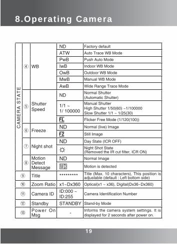
④ WB
ND Factory default
ATW Auto Trace WB Mode
PwB Push Auto Mode
IwB Indoor WB Mode
OwB Outdoor WB Mode
MwB Manual WB Mode
AwB Wide Range Trace Mode
⑤ShutterSpeed
ND Normal Shutter(Automatic Shutter)
1/1 ~ 1/ 100000
Manual ShutterHigh Shutter 1/50(60) ~1/100000Slow Shutter 1/1 ~ 1/25(30)
Flicker Free Mode (1/120(100))
⑥ FreezeND Normal (live) Image
Still Image
⑦ Night shotND Day State (ICR OFF)
Night Shot State(Removed the IR cut filter, ICR ON)
⑧MotionDetectMessage
ND Normal Image
Motion is detected
⑨ Title ********* Title (Max. 10 characters), This position is adjustable (default : Left bottom side)
⑩ Zoom Ratio x1~Dx360 Optical(x1 ~ x36), Digital(Dx36~Dx360)
⑪ Camera ID ID:000 ~ID:255
Camera Identification Number
⑫ Standby STANDBY Stand-by Mode
⑬ Power On Msg - Informs the camera system settings. It is
displayed for 2 seconds after power on.
CA
ME
RA
ST
AT
E8.Operating Camera
18 19
8.Operating Camera
Menu SetupUse the five buttons on back of the camera.
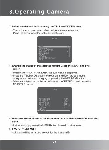
1. Press the MENU button to access the main setup mode.• Main setup menu is displayed on the monitor screen.• The Menu consists of the "Main-Menu" and "Sub-Menu"
2. Select the desired feature using the TELE and WIDE button.• Each pressing of the TELE or WIDE button moves the indicator to the next or previous feature.
SETUP
1.LENS [┛] 2.EXPOSURE [┛]3.WHITE BALANCE [┛]4.WDR/BLC [┛]5.DAY&NIGH [┛]6.IMAGE [┛]7.SPECIAL [┛]8.FACTORY DEFAULT 9.EXIT
NEAR/FAR
TELE
/WID
E
20 21
Funct ionSetup Key
TELE(UP) BUTTON
FAR(RIGHT) BUTTON
MENU BUTTON
WIDE(DOWN) BUTTON
NEAR(LEFT) BUTTON
8.Operating Camera
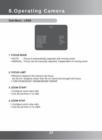
3. Select the desired feature using the TELE and WIDE button.• The indicator moves up and down in the main menu feature.• Move the arrow indicator to the desired feature.
4. Change the status of the selected feature using the NEAR and FAR button
• Pressing the NEAR/FAR button, the sub-menu is displayed. • Press the TELE/WIDE button to move up and down the sub-menu. category and set each category by pressing the NEAR/FAR button. • When completed, move the arrow indicator to "RETURN" and press the NEAR/FAR button.
5. Press the MENU button at the main-menu or sub-menu screen to hide the menu.
• It does not apply when the MENU button is used for other uses.
SETUP
1.LENS [┛] 2.EXPOSURE [┛]3.WHITE BALANCE [┛]4.WDR/BLC [┛]5.DAY&NIGH [┛]6.IMAGE [┛]7.SPECIAL [┛]8.FACTORY DEFAULT 9.EXIT
LENS
FOCUS MODE … AUTOFOCUS LIMIT … 50CMZOOM START … X1ZOOM STOP … X360ZOOM SPEED … V-FASTE-ZOOM … ONINITIALRETURN
6. FACTORY DEFAULT• All menu will be initialized except for the Camera ID
20 21
8.Operating Camera
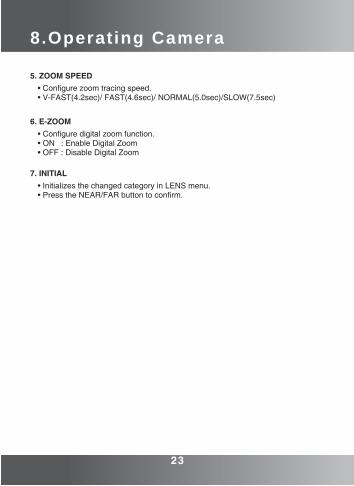
Sub-Menu : LENS
1. FOCUS MODE• AUTO : Focus is automatically adjusted with moving zoom.• MANUAL : Focus can be manually adjusted, independent of moving zoom.
LENS
FOCUS MODE … AUTOFOCUS LIMIT … 50CMZOOM START … X1ZOOM STOP … X360ZOOM SPEED … V-FASTE-ZOOM … ONINITIALRETURN
22 23
2. FOCUS LIMIT• Minimum distance the camera can focus. ex) 50 cm: Subjects closer than 50 cm cannot be brought into focus.• 1CM/10CM/50CM/1.5M/2M/3M/5M/10M/INF
3. ZOOM START• Configure zoom start ratio. • Can be set from x1 to x36.
4. ZOOM STOP• Configure zoom stop ratio.• Can be set from x1 to x360.
8.Operating Camera
5. ZOOM SPEED• Configure zoom tracing speed.• V-FAST(4.2sec)/ FAST(4.6sec)/ NORMAL(5.0sec)/SLOW(7.5sec)
6. E-ZOOM• Configure digital zoom function.• ON : Enable Digital Zoom• OFF : Disable Digital Zoom
7. INITIAL• Initializes the changed category in LENS menu.• Press the NEAR/FAR button to confirm.
22 23
8.Operating Camera
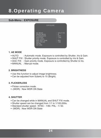
Sub-Menu : EXPOSURE
1. AE MODE• AUTO : Automatic mode. Exposure is controlled by Shutter, Iris & Gain.• SHUT FIX : Shutter priority mode. Exposure is controlled by Iris & Gain.• AGC FIX : Gain priority mode. Exposure is controlled by Shutter & Iris.• MANUAL : Manual mode.
2. BRIGHTNESS• Use this function to adjust image brightness.• Can be adjusted from 0(dark) to 15 (Bright).
3. FLICKERLESS• Flicker correction mode.• -(WDR) : Now WDR ON State
4. SHUTTER• Can be changed while in MANUAL and SHUT FIX mode.• Shutter speed can be changed from 1/1 to 1/100,000s.• Standard shutter speed : NTSC - 1/60. PAL - 1/ 50.• -(WDR) : Now WDR ON State
EXPOSURE
AE MODE … SHUT FIXBRIGHTNESS … 8FLICKERLESS … OFFSHUTTER … 1/60AGC LEVEL … -MAX AGC GAIN … MIDMAX FIELDS … 128INITIALRETURN
24 25
8.Operating Camera5. AGC LEVEL
• For brighter images, set to the desired value.• Can be changed from OFF to 36dB while in AGC FIX and MANUAL mode.
6. AGC LEVEL• Adjusts the maximum gain mode.• OFF, LOW, MID, HIGH, SUPER
7. MAX FIELDS• Adjusts the maximum accumulation fields.• Can be changed from OFF to 128FLD.
8. INITIAL• Initializes the changed category in EXPOSURE menu.• Press the NEAR/FAR button to confirm.
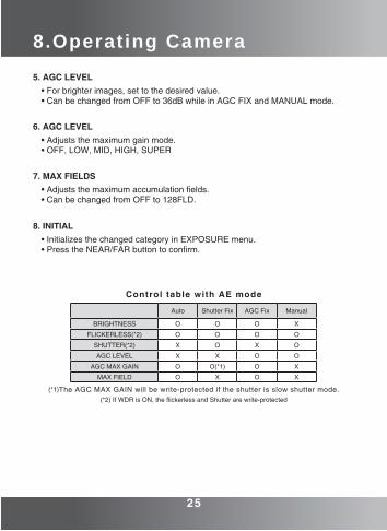
Control table with AE mode
Auto Shutter Fix AGC Fix Manual
BRIGHTNESS O O O X
FLICKERLESS(*2) O O O O
SHUTTER(*2) X O X O
AGC LEVEL X X O O
AGC MAX GAIN O O(*1) O X
MAX FIELD O X O X
24 25
(*1)The AGC MAX GAIN will be write-protected if the shutter is slow shutter mode.(*2) If WDR is ON, the flickerless and Shutter are write-protected
8.Operating Camera
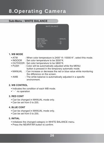
Sub-Menu : WHITE BALANCE
• ATW : When color temperature is 2400° K~10000 K°, select this mode.• INDOOR : Set color temperature to be 3200°K.• OUTDOOR : Set color temperature to be 5800°K.• PUSH : Color will be automatically adjusted while the MENU button is pressed in the temporary automatic mode.• MANUAL : Can increase or decrease the red or blue value while monitoring the difference on the screen. • AWB : The white balance is automatically adjusted in a specific environment.
1. WB MODE
• Indicates the condition of each WB mode. • ' - ' no operation
2. WB CONTROL
• Can be changed in MANUAL mode only.• Can be set from 0 to 255.
3. RED CONT
• Can be changed in MANUAL mode only.• Can be set from 0 to 255.
4. BLUE CONT
• Initializes the changed category in WHITE BALANCE menu.• Press the NEAR/FAR button to confirm.
5. INITIAL
WHITE BALANCE
WB MODE … MANUALWB CONTROL … -RED CONT … 30BLUE CONT … 50INITIALRETURN
26 27
8.Operating Camera
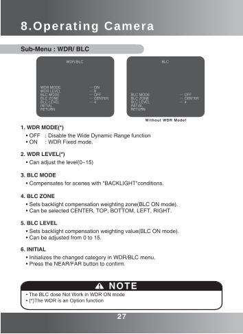
Sub-Menu : WDR/ BLC
WDR/BLC
WDR MODE … ONWDR LEVEL … 8BLC MODE … OFFBLC ZONE … CENTERBLC LEVEL … 4INITIALRETURN
26 27
• Initializes the changed category in WDR/BLC menu.• Press the NEAR/FAR button to confirm.
1. WDR MODE(*)• OFF : Disable the Wide Dynamic Range function• ON : WDR Fixed mode.
• Can adjust the level(0~15)2. WDR LEVEL(*)
• Compensates for scenes with "BACKLIGHT"conditions.3. BLC MODE
• Sets backlight compensation weighting zone(BLC ON mode).• Can be selected CENTER, TOP, BOTTOM, LEFT, RIGHT.
4. BLC ZONE
• Sets backlight compensation weighting value(BLC ON mode).• Can be adjusted from 0 to 15.
5. BLC LEVEL
6. INITIAL
• The BLC dose Not Work in WDR ON mode• (*)The WDR is an Option function
NOTE
BLC
BLC MODE … OFFBLC ZONE … CENTERBLC LEVEL … 4INITIALRETURN
Without WDR Model
8.Operating Camera
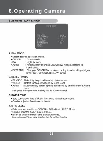
Sub-Menu : DAY & NIGHT
• Select desired operation mode. • COLOR : Day fix mode.• BW : Night fix mode.• AUTO : Automatically changes COLOR/BW mode according to illuminance.• EXTERNAL : Changes COLOR/BW mode according to external input signal. B/W(HIGH, +5V) COLOR(LOW, GND)
1. D&N MODE
• SENSOR : Detect lighting conditions by photo-sensor.• VIDEO : Detect lighting conditions by video level.• AUTO : Automatically detect lighting conditions by photo-sensor & video level.
2. DETECT MODE
• Sets conversion time of IR cut filter while in automatic mode.• Can be adjusted from 0 sec to 10 sec.
3. DWELL TIME
• Sets turnover level from COLOR to BW while in AUTO Mode.• Can be adjusted from 1 Lux to 90 Lux. • It can be adjusted under sets SENSOR mode.
4. D→N LEVEL
Sets up the level higher while installing into the outdoor housing.
DAY & NIGHT
D&N MODE … AUTODETECT MODE … SENSORDWELL TIME … 1 SECD→N LEVEL … 1 Lux N→D LEVEL … 10 Lux BURST(NIGHT) … ONINITIALRETURN
Sets up the level higher while installing into the outdoor housing.
28 29
8.Operating Camera
• Sets turnover level from BW to COLOR while in AUTO Mode.• Can be adjusted from 3 Lux to 100 Lux.• It can be adjusted under sets SENSOR mode.
5. N→D LEVEL
• Select the burst signal ON/OFF when NIGHT(ICR ON) mode.6. BURST(NIGHT)
• Initializes the changed category in DAY & NIGHT menu.• Press the NEAR/FAR button to confirm.
7. INITIAL
28 29
8.Operating Camera
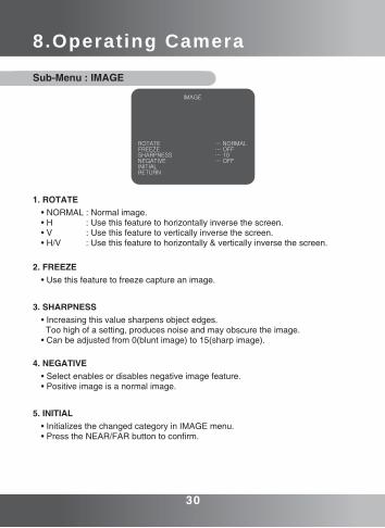
Sub-Menu : IMAGE
• NORMAL : Normal image.• H : Use this feature to horizontally inverse the screen.• V : Use this feature to vertically inverse the screen.• H/V : Use this feature to horizontally & vertically inverse the screen.
1. ROTATE
• Use this feature to freeze capture an image.2. FREEZE
• Increasing this value sharpens object edges. Too high of a setting, produces noise and may obscure the image.• Can be adjusted from 0(blunt image) to 15(sharp image).
3. SHARPNESS
• Select enables or disables negative image feature.• Positive image is a normal image.
4. NEGATIVE
• Initializes the changed category in IMAGE menu.• Press the NEAR/FAR button to confirm.
5. INITIAL
IMAGE
ROTATE … NORMALFREEZE … OFF SHARPNESS … 10NEGATIVE … OFFINITIALRETURN
30 31
8.Operating Camera
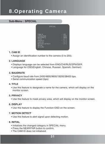
Sub-Menu : SPECIAL
• Assign an identification number to the camera (0 to 255).1. CAM ID
• Displays language can be selected from ENG/CHI/RUS/SPN/GER.• Language for OSD(English, Chinese, Russian, Spanish, German)
2. LANGUAGE
• Configure baud rate from 2400/4800/9600/19200/38400 bps.• Serial communication speed (bps)
3. BAUDRATE
• Use this feature to designate a name for the camera, which will display on the monitor screen.
4. TITLE
• Use this feature to mask privacy area, which will display on the monitor screen.5. PRIVACY
• Use this feature to display the Function-OSD on the screen.6. DISPLAY
• Use this feature to alert signal upon detecting motion.7. MOTION DETECT
• Initializes the changed category in SPECIAL menu.• Press the NEAR/FAR button to confirm. • The CAM ID does not initialized.
8. INITIAL
SPECIAL
CAM ID … 001LANGUAGE … ENGBAUDRATE … 9600TITLE … [┛]PRIVACY … [┛]DISPLAY … [┛]MOTION DETECT … [┛]INITIALRETURN
30 31
8.Operating Camera
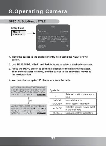
SPECIAL Sub-Menu : TITLE
1. Move the cursor to the character entry field using the NEAR or FAR button.
2. Use TELE, WIDE, NEAR, and FAR buttons to select a desired character.
3. Press the MENU button to confirm selection of the blinking character. Then the character is saved, and the cursor in the entry field moves to the next position.
4. You can choose up to 156 characters from the table.
TITLE
↓CAM TITLE [M] select----------- ABCDEFGHIJKLMNOPQRSTUVWXYZa b c d e f g h i j k l m n o p q r s t u v w x y z0123456789ÄÖÜÈÆäöüáéíñóúßæSPACE>> <<BACK MORE>> LOCATION … [┛]RETURN
Entry FieldMax.10Character
ABCDEFGHIJKLMNOPQRSTUVWXYZabcde fgh i j k lmnopqrs tuvwxyz 0123456789ÄÖÜÈÆäöüáéíñóúßæSPACE>> <<BACK MORE>>
АБВГДЕЁЖЗИЙКЛМНОПРСТУФХЦЧШЩЪЫЬЭЮЯⓞ①②③④⑤⑥⑦⑧⑨■△▽▷◁▶◀▲▼ %#&/!?[]()<>↕↑↓→←☞*,.;:‘“•SPACE>> <<BACK MORE>>
↕[M]
Symbols
↓Selected position in the entry field
"A"~“æ” Normal characterSPACE>> Insert space " "character
<<BACK Selected position moves to left in the entry field
MORE>> Displays another characters.
32 33
8.Operating Camera
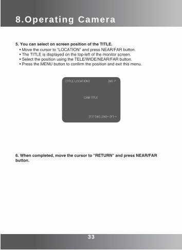
5. You can select on screen position of the TITLE. • Move the cursor to "LOCATION" and press NEAR/FAR button.• The TITLE is displayed on the top-left of the monitor screen.• Select the position using the TELE/WIDE/NEAR/FAR button.• Press the MENU button to confirm the position and exit this menu.
6. When completed, move the cursor to "RETURN" and press NEAR/FAR button.
[TITLE LOCATION] [M] ┛
CAM TITLE
[T]↑[W]↓[N]←[F]→
32 33
8.Operating Camera
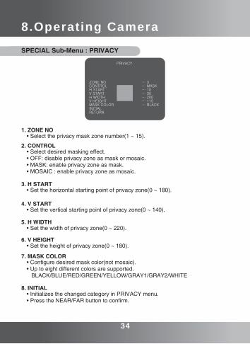
SPECIAL Sub-Menu : PRIVACY
1. ZONE NO• Select the privacy mask zone number(1 ~ 15).
2. CONTROL• Select desired masking effect.• OFF: disable privacy zone as mask or mosaic.• MASK: enable privacy zone as mask.• MOSAIC : enable privacy zone as mosaic.
3. H START• Set the horizontal starting point of privacy zone(0 ~ 180).
4. V START• Set the vertical starting point of privacy zone(0 ~ 140).
5. H WIDTH• Set the width of privacy zone(0 ~ 220).
6. V HEIGHT• Set the height of privacy zone(0 ~ 180).
7. MASK COLOR• Configure desired mask color(not mosaic).• Up to eight different colors are supported. BLACK/BLUE/RED/GREEN/YELLOW/GRAY1/GRAY2/WHITE
8. INITIAL• Initializes the changed category in PRIVACY menu.• Press the NEAR/FAR button to confirm.
PRIVACY
ZONE NO … 3CONTROL … MASKH START … 10V START … 30H WIDTH … 200V HEIGHT … 110MASK COLOR … BLACKINITIALRETURN
34 35
8.Operating Camera
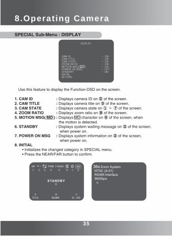
SPECIAL Sub-Menu : DISPLAY
1. CAM ID : Displays camera ID on ⑪ of the screen.2. CAM TITLE : Displays camera title on ⑨ of the screen.3. CAM STATE : Displays camera state on ① ~ ⑦ of the screen.4. ZOOM RATIO : Displays zoom ratio on ⑩ of the screen.5. MOTION MSG( MD ) : Displays MD character on ⑧ of the screen, when the motion is detected.6. STANDBY : Displays system waiting message on ⑫ of the screen, when power on.7. POWER ON MSG : Displays system information on ⑬ of the screen, when power on.8. INITIAL • Initializes the changed category in SPECIAL menu. • Press the NEAR/FAR button to confirm.
Use this feature to display the Function-OSD on the screen.
DISPLAY
CAM ID … ONCAM TITLE … ONCAM STATE … ONZOOM RATIO … ONMOTION MSG( MD ) … ONPOWER ON MSG … OFFSTANDBY … ONINITIALRETURN
34 35
36x
Dx360
8.Operating Camera
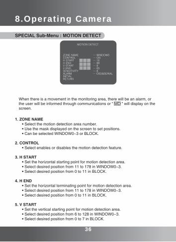
SPECIAL Sub-Menu : MOTION DETECT
1. ZONE NAME • Select the motion detection area number. • Use the mask displayed on the screen to set positions. • Can be selected WINDOW0~3 or BLOCK.
2. CONTROL • Select enables or disables the motion detection feature.
3. H START • Set the horizontal starting point for motion detection area. • Select desired position from 11 to 178 in WINDOW0~3. • Select desired position from 0 to 11 in BLOCK.
4. H END • Set the horizontal terminating point for motion detection area. • Select desired position from 11 to 178 in WINDOW0~3. • Select desired position from 0 to 11 in BLOCK.
5. V START • Set the vertical starting point for motion detection area. • Select desired position from 6 to 128 in WINDOW0~3. • Select desired position from 0 to 7 in BLOCK.
When there is a movement in the monitoring area, there will be an alarm, or the user will be informed through communications or " MD " will display on the screen.
MOTION DETECT
ZONE NAME … WINDOW0CONTROL … ONH START … 16H END … 88V START … 9V END … 65SENSITIVITY … 8ALARM … OSD&SERIALINITIALRETURN
36 37
8.Operating Camera
6. V END • Set the vertical starting point for motion detection area. • Select desired position from 6 to 128 in WINDOW0~3. • Select desired position from 0 to 7 in BLOCK.
7. SENSITIVITY • Increase or decrease detection sensitivity value. • Can be set from 1 (low response) to 15 (sensitive).
8. ALARM • Select desired alert type. • OSD : The WINDOW or BLOCK will be displayed on the screen when motion is detected. • SERIAL : Alert packet is transmitted via RS-485 when motion is detected. • OSD&SERIAL : Use OSD and SERIAL feature simultaneously.
9. INITIAL • Initializes the changed category in MOTION DETECT menu. • Press the NEAR/FAR button to confirm.
36 37
9.Communication Protocol
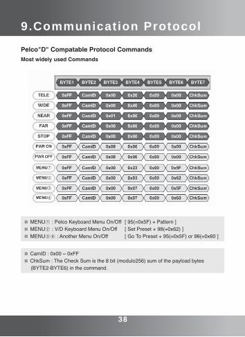
Pelco"D" Compatable Protocol CommandsMost widely used Commands
38 39
9.Communication Protocol
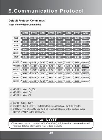
Default Protocol CommandsMost widely used Commands
• The camera can be controlled by VISCA(SONY), LG, Pelco-P Compatable Protocol. For more detailed informations refer to their manuals.
NOTE
38 39
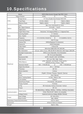
10.Specif icationsModel WDR (Wide Dynanic Range) High RES. Zoom
Signal System NTSC PAL
CCD
Image Sensor 1/4” Sony Double Scan Exview HAD CCD
Total Pixels 811(H) x 508(V) 795(H) x 596(V)
Effective Pixels 768(H) x 494(V) 752(H) x 582(V)
Optics
Lens 36x, f=3.4~122.4mm(F1.6 ~F4.5)
Min. Object Distance 0.01m(W) ~ 1.5m(T)
Digital Zoom 1x ~ 10x
Angle Field of View Horizontal : 57.8 degrees(Wide) to 1.7 degrees(Tele)
Sync.
Scanning System 2:1 Interlace
Sync. System Internal/Line-lock
Frequency H:15.734 KHz V:59.94 Hz H:15.625KHz V:50 Hz
Electrical
Horizontal Resolution 550 TV Lines
Camera Title Off/On(Displayed 10 characters)
Camera ID 256 ID Selectable
Video Output 1.0Vp-p/75Ω
S/N Ratio More than 50dB (AGC Off, DSS Off)
Min. Illumination 0.3 Lux : Color, 0.1Lux : BW (30 IRE @ Wide End, AGC Super, DSS Off)
Backlight Compensation Off/On (Level Adjustable, Area Selectable)
WDR Off / On (Level Adjustable)
Mechanical D&N AUTO / COLOR / B/W / EXTERNAL
Gain Control Off / Low / Mid / High / Super
White Balance ATW / INDOOR / OUTDOOR / PUSH AUTO / MANUAL(R Gain, B Gain) / AWB
Electronic Shutter 1/60 ~ 1/100,000 sec 1/50 ~ 1/100,000 sec
Digital Slow Shutter Off, 2 ~ 128 Field
Flickerless Off / On
Motion Detection 5 Zones
OSD English / Chinese / Russian / Spanish / German
Focus Auto / Manual
Zoom Tracking Speed 4.2 Sec : Wide to Tele
Lens Initialize Support
Zoom/Focus Preset 512 internal / 128 external
Privacy Function 15 Zones
E-Flip Off, Horizontal, Vertical, Horizontal / Vertical
Freeze Off / On
CommunicationSerial Control
RS-485(2400bps, 4800bps, 9600bps, 19200bps, 38400bps Selectable)
KT&C, PELCO-D/P, VISCA, LG compatible
Voltage Control External Control by Voltage (ZOOM, FOCUS)
PowerInput Voltage DC 12V(±10%)
Input Current Max. 350mA
Operating Temperature/Humidity -10°C to +50°C
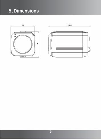
Dimension 67mm X 73mm X 119.5mm
Weight Approx. 502g
40
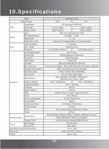
10.Specif icationsModel High RES. Zoom
Signal System NTSC PAL
CCD
Image Sensor 1/4” Sony Super HAD CCDⅡ
Total Pixels 811(H) x 508(V) 795(H) x 596(V)
Effective Pixels 768(H) x 494(V) 752(H) x 582(V)
Optics
Lens 36x, f=3.4~122.4mm(F1.6 ~F4.5)
Min. Object Distance 0.01m(W) ~ 1.5m(T)
Digital Zoom 1x ~ 10x
Angle Field of View Horizontal : 57.8 degrees(Wide) to 1.7 degrees(Tele)
Sync.
Scanning System 2:1 Interlace
Sync. System Internal/Line-lock
Frequency H:15.734 KHz V:59.94 Hz H:15.625KHz V:50 Hz
Electrical
Horizontal Resolution 550 TV Lines
Camera Title Off/On(Displayed 10 characters)
Camera ID 256 ID Selectable
Video Output 1.0Vp-p/75Ω
S/N Ratio More than 50dB (AGC Off, DSS Off)
Min. Illumination 0.2 Lux : Color, 0.06Lux : BW (30 IRE @ Wide End, AGC Super, DSS Off)
Backlight Compensation Off/On (Level Adjustable, Area Selectable)
Mechanical D&N AUTO / COLOR / B/W / EXTERNAL
Gain Control Off / Low / Mid / High / Super
White Balance ATW / INDOOR / OUTDOOR / PUSH AUTO / MANUAL(R Gain, B Gain) / AWB
Electronic Shutter 1/60 ~ 1/100,000 sec 1/50 ~ 1/100,000 sec
Digital Slow Shutter Off, 2 ~ 128 Field
Flickerless Off / On
Motion Detection 5 Zones
OSD English / Chinese / Russian / Spanish / German
Focus Auto / Manual
Zoom Tracking Speed 4.2 Sec : Wide to Tele
Lens Initialize Support
Zoom/Focus Preset 512 internal / 128 external
Privacy Function 15 Zones
E-Flip Off, Horizontal, Vertical, Horizontal / Vertical
Freeze Off / On
CommunicationSerial Control
RS-485(2400bps, 4800bps, 9600bps, 19200bps, 38400bps Selectable)
KT&C, PELCO-D/P, VISCA, LG compatible
Voltage Control External Control by Voltage (ZOOM, FOCUS)
PowerInput Voltage DC 12V(±10%)
Input Current Max. 320mA
Operating Temperature/Humidity -10°C to +50°C
Dimension 67mm X 73mm X 119.5mm
Weight Approx. 502g
41


![HD Integrated Camera Model No. AW-HE2P AW-HE2E · the CAMERA OSD button on/off and the camera menu display/non-display not matching. To get back to the previous screen Select [ ]](https://img.pdfslide.us/doc/110x75/60270785baa1fa02d64ba70f/hd-integrated-camera-model-no-aw-he2p-aw-he2e-the-camera-osd-button-onoff-and.jpg)