Embed Size (px)
Citation preview

3600O2.OM.E9903
3600 Analyzer for OxygenOperator’s Manual
Series 3600/3600M Indicating Instrument / Model 311xx Oxygen Sensor
© 1999 Orbisphere. Printed in Switzerland.

2 3600 Analyzer for O2 Measurement—Operator’s Manual
3600O2.OM.E9903
CE conformity
The 3600 / 3600M indicating instrument is manufactured conforming to the requirements of theelectromagnetic compatibility directive: 89 / 336 / CEEand the low voltage directive: 73 / 23 / CEE
The instrument complies with all the requirements of the following electromagneticcompatibility standards:
– 3600 instrument:
EN 50081-1 (Jan. 1992), EN 50081-2 (Nov. 1993), and EN 50082-1 (Jan. 1992)
As a result, the 3600 instrument can be used in residential and commercial sites, and forlight industry. It is designed for indoor use in a protected area.
– 3600M instrument:
EN 50081-1 (Jan. 1992), EN 50081-2 (Nov. 1993), and EN 50082-2 (Mar. 1995)
As a result, the 3600M instrument can be used in typical industrial locations.
The 3600 / 3600M instrument satisfies the conditions of the safety standard: EN 61010-1(1993)
The 3600 / 3600M instrument is developed, manufactured, and inspected by Orbisphere, whichis certified in accordance with the quality standard: ISO 9001 / EN 29001
The tests for safety and for electromagnetic compatibility were performed by the CEM testlaboratory (EMC Fribourg SA, zone industrielle de Montenaz, CH-1728 Rossens) which isacknowledged by the Swiss Federal Office of Metrology.
Supplementary safety recommendationsFor safe operation of the instrument, it is imperative that these service instructions be read and
that the safety recommendations mentioned herein be scrupulously respected.
Opening the instrument exposes non-insulated electrical components with hazardous voltages.Therefore the instrument should not be opened. If repairs or adjustments are necessary, the
instrument should be returned to an authorized Orbisphere service center.
If these danger warnings are not heeded, serious material or bodily injury could occur.
Dacron, Delrin, Tedlar, Tefzel, and Viton are registered trademarks of DuPont.Hastelloy is a registered trademark of Haynes International.Kynar is a registered trademark of The Pennwalt Corporation.Monel is a registered trademark of IMCO Alloys International, Inc.Saran is a registered trademark of Dow Chemical Co.Swagelok is a registered trademark of Swagelok Co.Microsoft and Windows are registered trademarks of Microsoft Corporation.

3600 Analyzer for O2 Measurement—Operator’s Manual 3
3600O2.OM.E9903
Table of contents
1. Operating Instructions ................................................................................. 51.1 What you have received........................................................................................ 51.2 What to check before using the system................................................................ 61.3 Instrument Operation........................................................................................... 8
1.3.1 Program Flow Charts ...................................................................................................... 91.3.2 Oxygen Measurement ................................................................................................... 10
1.3.2.1 Warning Messages.....................................................................................................................111.3.3 Calibration Menus ......................................................................................................... 12
1.3.3.1 Instrument Barometric Pressure Calibration ..........................................................................121.3.3.2 Oxygen Sensor Calibration in Air .............................................................................................121.3.3.3 Oxygen Sensor Direct Calibration...........................................................................................141.3.3.4 Model 28117 External Pressure Sensor Calibration...............................................................141.3.3.5 Model 32646.E Hydrogen Compensation for Oxygen Sensor ..............................................16
1.4 Modify Options Menus ........................................................................................ 171.4.1 Display Units ................................................................................................................. 181.4.2 Thermal Cutoff.............................................................................................................. 201.4.3 Alarm Outputs............................................................................................................... 20
1.4.3.1 Alarms Description ...................................................................................................................211.4.4 Analog Outputs.............................................................................................................. 21
1.4.4.1 Analog Outputs Description.....................................................................................................221.4.5 Serial Output................................................................................................................. 241.4.6 Salinity and Chlorinity Adjustments ................................................................................ 241.4.7 H2 Compensation Option (Model 32646.E)................................................................... 251.4.8 Self Diagnostics ............................................................................................................. 251.4.9 Rolling Average.............................................................................................................. 261.4.10 Gas to Measure, CO2/H2S Insensitivity......................................................................... 261.4.11 Membrane Selection.................................................................................................... 27
1.5 Maintenance (Sensor Service) ............................................................................ 281.5.1 When to Perform a Sensor Service................................................................................ 281.5.2 Remove Sensor from Sample......................................................................................... 281.5.3 Prepare Sensor for Cleaning.......................................................................................... 281.5.4 Electrochemical Cleaning............................................................................................... 291.5.5 Chemical Cleaning......................................................................................................... 29
1.5.5.1 Ammonia Cleaning ....................................................................................................................301.5.5.2 Nitric acid Cleaning ...................................................................................................................30
1.5.6 Polish Sensor Face......................................................................................................... 301.5.7 Replace Membrane........................................................................................................ 311.5.8 Put Sensor Back into Service.......................................................................................... 321.5.9 Shutting Down the System............................................................................................. 321.5.10 Troubleshooting .......................................................................................................... 33
1.6 Spare Parts ......................................................................................................... 341.6.1 Oxygen Sensor and Protection Cap Diagram ................................................................. 35
1.7 Data Acquisition Software.................................................................................. 371.7.1 Program Setup .............................................................................................................. 37
1.7.1.1 Windows 3.1 Setup...................................................................................................................371.7.1.2 Windows 95 Setup....................................................................................................................37
1.7.2 Menu Overview............................................................................................................. 381.7.3 Configuring the Program ............................................................................................... 381.7.4 Acquiring Data............................................................................................................... 391.7.5 Printing, Copying, and Saving Data................................................................................. 40
1.8 Warranty Information......................................................................................... 411.8.1 About this Manual.......................................................................................................... 41

4 3600 Analyzer for O2 Measurement—Operator’s Manual
3600O2.OM.E9903
2. Installation Guidelines.................................................................................422.1 Instrument Installation .......................................................................................42
2.1.1 Panel or 19-inch Rack Mount Instrument Installation...................................................... 422.1.1.1 Instrument Mounting................................................................................................................ 422.1.1.2 Power Input .............................................................................................................................. 442.1.1.3 Electrical Signal Connections.................................................................................................... 44
2.1.2 Wall Mount Instrument Installation................................................................................. 462.1.2.1 Instrument Mounting................................................................................................................ 462.1.2.2 Power Input .............................................................................................................................. 472.1.2.3 Electrical Signal Connections.................................................................................................... 48
2.1.3 Portable Instrument Installation ..................................................................................... 482.1.3.1 Instrument Mounting................................................................................................................ 482.1.3.2 Power Input .............................................................................................................................. 482.1.3.3 Electrical Signal Connections.................................................................................................... 49
2.1.4 Instrument Connectors.................................................................................................. 502.1.4.1 Oxygen Sensor Wiring Identification....................................................................................... 502.1.4.2 External Pressure Sensor Input Wiring Identification............................................................. 502.1.4.3 RS-232 Wiring Identification.................................................................................................... 502.1.4.4 Recorder Output Wiring Identification ................................................................................... 512.1.4.5 Alarm Output Wiring Identification......................................................................................... 51
2.1.5 User-supplied Cabling Requirements............................................................................. 522.1.6 LEMO Connector Assembly Instructions ....................................................................... 522.1.7 Cable Gland Wiring Instructions .................................................................................... 522.1.8 Instrument Servicing ...................................................................................................... 53
2.1.8.1 Battery Replacement (portable instrument) .......................................................................... 542.1.8.2 Analog Current to Voltage Output Conversion ..................................................................... 542.1.8.3 Internal Fuse Replacement....................................................................................................... 54
2.2 Sensor Installation ..............................................................................................552.2.1 Model 29501 Sensor Socket Installation ........................................................................ 552.2.2 Model 32003 ProAcc Insertion/Extraction Valve Installation .......................................... 562.2.3 Model 32001.x Flow Chamber Installation .................................................................... 562.2.4 Model 32002.x Multiparameter Flow Chamber Installation ........................................... 582.2.5 Model 28117 External Pressure Sensor Installation ....................................................... 59
3. Technical Information .................................................................................603.1 System Specifications..........................................................................................603.2 Principle of Operation.........................................................................................62
Appendix 1—Table of Oxygen Concentrations (ppm) ...................................63
Index................................................................................................................69

3600 Analyzer for O2 Measurement—Operator’s Manual 5
3600O2.OM.E9903
1. Operating Instructions1.1 What you have received
Your 3600 analyzer for oxygen measurements includes two basic components:
• A model 3600/1xx or 3600M/1xx Indicating Instrument, available as aportable, process (panel or 19-inch rack mount), or wall mount unit; and
• A model 311xx.xx Oxygen Sensor.
These components are available in a variety of configurations, listed in section 3.
Indicating instrument, front panel
The front panel includes a key-lock to switch on the instrument; a two-line liquidcrystal display (LCD), displaying 16 characters across; a “ ” switch to illuminatethe LCD for three minutes when connected to an outside power source; plus fourcontrol keys. Complete operating instructions for this instrument follow—notethat a “Program Flow Chart” in section 1.3.1 gives a handy overview of all on-screen instructions, in the order they appear.
The sensor has a threaded collar and storage cap on top. A plastic screw-on base atits rear provides a stand for servicing, and protects the screw-on 10-pin LEMOconnection. The sensor cable has a mating LEMO-10 connector.
Oxygen sensor components, plus sensor cable and base—exploded view
A sensor recharge kit, in a blue plastic case, is also included with your shipment.Inside this kit are the materials to maintain your sensor, such as membranes, aspecial membrane mounting tool, polishing powder, and a polishing cloth. Thecontents of this recharge kit are listed in section 1.6.
Check to see that any needed mounting hardware has been included. This varieswith each shipment, but in general a flow chamber, multi-parameter flow chamber(where a model 28117 external pressure sensor also can be mounted), or sensorsocket is usually needed to bring the sensor in contact with the gaseous or liquidsample. Note that the “Installation Guidelines” in section 2 of this manual includeall the instructions you will need to set up your system. Please refer to this sectionnow if you are still in the process of configuring your installation.

6 3600 Analyzer for O2 Measurement—Operator’s Manual
3600O2.OM.E9903
1.2 What to check before using the systemBefore making initial measurements, first:
Check the voltage and line power—The indicating instrument is available in115 VAC, 230 VAC, and 10–30 VDC versions. A sticker on the rear panel indicateswhich voltage you have. Make sure that it is correct before connecting to a powersupply. Make sure that the ground of the AC supply is connected.
The DC connection must be made by the user, as described in section 2.1.
Note that the portable version can operate without connection to an externalpower supply for a period up to 16 hours. If your instrument periodically displaysa “LOW BATTERY” message, it is necessary to recharge the batteries by pluggingthe instrument into a power supply and leaving it plugged in overnight.
Check instrument mounting—The instrument is available in portable, process(panel or 19" rack mount), or wall mount versions. If you are still configuring yourinstallation, refer to section 2.1 for relevant mounting information.
Check instrument connections—The instrument includes connections for linepower, the oxygen sensor, and an optional external pressure sensor. In addition,the output pack (optional on portable instruments) includes alarm outputs, analogcurrent outputs, and an RS-232 serial output. Refer to section 2.1 for completewiring and connection information.
Check the oxygen sensor—Shipping conditions can adversely affect Orbisphereoxygen sensors. You should perform a sensor service as described in section 1.5before trying to make measurements.
However, if you intend to make trial measurements with the sensor as shipped,first examine the sensor head. To do this, remove the plastic base at the bottom ofthe sensor, then unscrew the calibration cap by loosening its collar.
Your sensor head is fitted with a screw-on protection cap. For a view of the sensorhead, you must remove the cap, using the wrench supplied in your recharge kit.Do this carefully, making sure not to disturb the membrane that covers the sensorhead, held in place by a membrane holding ring.
O2 sensor components, including exploded view of membrane assembly order

3600 Analyzer for O2 Measurement—Operator’s Manual 7
3600O2.OM.E9903
You should be able now to view the gold cathode, or “working electrode”, in thecenter; a guard ring electrode surrounds the cathode, separated by a fine groove.
The anode, or “counter electrode”, is underneath the membrane support. You willget a better look at all these components during your first sensor service. Beforemaking a measurement, check the sensor head to see that:
• The membrane holding ring is firmly in place,
• The membrane surface is smooth and wrinkle-free,
• The electrolyte beneath the membrane is free of bubbles,
• The electrodes appear clear, clean, and bright.
Check sensor placement—The oxygen sensor can be placed:
• In a flow chamber (for on-line sampling, that is, samples drawn off line by6-mm or ¼-inch tubing);
• In a sensor socket or ProAcc insertion/extraction valve for measurementsmade directly in a sampling pipe; or
• Directly into “loose” liquid or gas-phase samples.
Check to see that the sensor installation recommendations in the InstallationGuidelines, section 2.2, are followed before proceeding with measurements.

8 3600 Analyzer for O2 Measurement—Operator’s Manual
3600O2.OM.E9903
1.3 Instrument OperationOnce you have reviewed the previous sections of this manual, connect the sensorto the instrument and turn the keyswitch to the horizontal “on” position. Thesystem automatically starts in “measurement” mode.
Front Panel Keyswitch
The instrument function keys are active only if the keyswitch is in the horizontal“on” position. Choose the vertical “locked” position when measuring, to avoidaccidental or unauthorized parameter modification.
Instrument Function Keys
The red “ESC” key lets you jump back a step in the program. Following the flowchart in section 1.3.1, you will see, for example, if your instrument were displayingthe “Measurement” menu, pressing “ESC” would return you to “MeasureOptions Calibrate” (also known as the “main menu”).
MEASURE OPTIONS CALIBRATE
Use the yellow “ñ” and “ò” arrow keys to scroll through available options atvarious stages of operation. Pressing “ñ” moves the “blink” from right to left and“ò” moves it in the opposite direction. During measurement, use these keys to fixon a specific displayed measurement range, as described in section 1.3.2.
The red “ENTER” key (“DO” on older instruments) lets you select an item. Notethat when inputting numbers (for example, an alarm limit) the menu displays fourdigits, with one digit highlighted by the symbol “^”. This digit is incremented bypressing “ñ” key and decremented by pressing “ò”. Pressing “ENTER” shifts thehighlight one digit to the right, until last digit, in which case the new whole value ismemorized. (Note that if power is disconnected, the system remembers any valuesentered via the “ENTER” key when power is resumed.)
The “ENTER” key also activates a single RS-232 transmission when theinstrument is measuring (and the RS-232 output is in “Manual” mode, asdescribed in section 1.4.5).
For most installations, calibrating the instrument’s internal atmospheric pressuresensor and calibrating the O2 sensor in air are necessary first steps. The instrumentis factory calibrated for typical applications. However, it is recommended that yourecalibrate the O2 sensor before making any measurements, using the proceduresdescribed in section 1.3.3.
You may wish to familiarize yourself with the “Modify Options” menus describedin section 1.4. Your instrument is pre-set with certain default values, which enableyou to get started on actual measurements with a newly delivered system, but lateryou may need to make other choices of parameters.

3600 Analyzer for O2 Measurement—Operator’s Manual 9
3600O2.OM.E9903
1.3.1 Program Flow ChartsThe following flow chart depicts the menus you encounter when the instrument isfirst turned on, and an overview of the menu choices. The Measure menu isdescribed further in section 1.3.2. The Calibration menus depicted below aredescribed further in section 1.3.3. The Modify Options menus are described inmore detail in section 1.4.
The flow lines are keyed to specific instrument actions. Note that when more thanone item is available within the same menu, the chart uses ellipses (“. . .”) to showthat there are more choices to follow (but you will not see the ellipses on screen).You may highlight any one of these choices by pressing “ñ” or “ò”.
MEASURE OPTIONSCALIBRATE
CALIBRATIONIN AIR
(See section 1.6 forModify Options menus)
O2 = 7.024 pmv 3T = 22.3 °C
METHODTWO POINTS
V.32603-05.X18/2/98
Main Menu
CALIBRATIONDIRECT
Calibration Menu
Change range
CALIBRATIONBAROM. PRESSURE
MODIFY OPTIONSDISPLAY UNITS
CALIBRATIONEXTERN. PRESSURE
NOW XXX% OFLAST CALIBRATION
CALIBRATIONOUT OF BOUNDS
CALIBRATIONCOMPLETE
NOW XXX% OFEXPECTED CURRENT
CALIBRATION 0000CONDITION ^
CC = 8.123 pmv 3UP/DOWN MODIFIES
NOW XXX% OFLAST CALIBRATION
CALIBRATIONOUT OF BOUNDS
CALIBRATIONCOMPLETE
NOW XXX% OFEXPECTED CURRENT
PRESSURE XXXX mbar
BAROMETRIC 0000PRESSURE ^
after first calibration
CURRENT XX.XX nA
EXTERN. PRESSURE XXXX mbar
LOW POINT 0000bar ^
CALIBRATIONPURE HYDROGEN
NOW XXX % OF LAST CALIBRATION
H2 PRESSURE 0000(CAL) mbar ^
available as option 32646.E
METHODDEFAULT
after first calibration
METHODONE POINT
Options Menu
ONE POINT 0000mbar ^
PRESSURE SENSOR50 psia
HIGH POINT 0000bar ^
after first calibration
AUTOMATIC (no keystroke required)
ESC
UP/DOWN
ENTER

10 3600 Analyzer for O2 Measurement—Operator’s Manual
3600O2.OM.E9903
1.3.2 Oxygen MeasurementTypical 3600 instruments are delivered with the appropriate measurement andmembrane selections pre-set for your application. However, you can change thesesettings if desired. Instructions for the various “options” included are found insection 1.4, the Modify Options Menu.
The simplest way to check if your system is pre-set for the right measurementunits is to place the system in oxygen measurement mode. Switch on theinstrument (if necessary) to bring up the “Measurement” mode (or select it fromthe “Measure Options Calibrate” menu by using the yellow “ñ” or “ò” key ifnecessary). You should see a screen like this.
O2 = 00.00 xxx 3T = 00.0° x ∞
(Note that your system will display actual numerical values in place of the zeros,and units of measurements for the “x’s” shown here.) If the unit of measurementon the top line is as expected—for example, in parts per million expressed as“ppm”—and the appropriate temperature measurement value is expressed (°C,°K, or °F), then you should be ready to begin to make measurements by placingyour sensor in the sample. (The infinity symbol “∞” only appears as shown whenthe system is “busy”, that is, occupied with an internal operation for a fewseconds. Keyboard input will not be accepted during these interruptions.)
Range indicationThe range indication appears at the rightmost position of the display’s top line. Ifthe last position in this line is blank, then you are operating in autoranging mode.Otherwise, a single digit from 1 to 5 appears, to show which fixed range theinstrument is in. Pressing the “ñ” key will scan this digit upward (“ò” goesdownward) through the permitted “number of ranges” (see section 1.4.1), until itgoes blank, to show that the autoranging mode has been reached. You will also seethe “resolution” of the displayed concentration changing. For example, if you areconfigured for three ranges, then you can scan upward through the sequence...blank-1-2-3-blank... etc. You may see the following message on one or morefixed ranges (shown here as “Range 3”) during this sequence:
OVERRANGE RANGE 3
This means that the measured oxygen concentration exceeds the upper limits ofthese ranges. Normal corrective action is to press the “ñ” key to reach a lesssensitive range, of which the upper limit exceeds the measured oxygenconcentration. Note that you may see an “Overrange Range 0” message as well.This is an indication that you are measuring outside the normal limits while inautoranging mode.
Before making measurements, you should familiarize yourself with the “ModifyOptions” menus described in section 1.4. While your instrument is pre-set withcertain default values to anticipate your measurement conditions (for example,number of ranges, dissolved vs. partial pressure), you may change these for yourapplication.
What to expect during oxygen measurementAny sensor previously exposed to the air (or to air-saturated liquid) will, onceplaced in a typical sample, generate a signal that decays rapidly at first, then moreslowly as it approaches the actual oxygen level.

3600 Analyzer for O2 Measurement—Operator’s Manual 11
3600O2.OM.E9903
It is normal for the rightmost digits to vary slightly; this is a reaction to slightvariations in oxygen content. However, if drastic changes in temperature occur atthe sensor while in use, correct readings will lag as the sensor adjusts to the newtemperature. The instrument’s response time depends on the membrane used,anywhere from 7.2 seconds, to 90 seconds, for 90% of total change at 25°C.(These and other data are found in section 3, “Technical Information”.)
Measurement outputsThe 3600 instrument provides several analog output signals. The analog outputsrepresent the measured oxygen concentration, sample temperature, pressure, anda range indication. These signals are available as 0–5 Volts, 0–20 mA, or 4–20 mA.You can rescale the oxygen concentration output for your applicationrequirements. See section 1.4.4 for further description of these analog outputs.
In addition, alarm relay contacts are available in certain 3600 instrument models.The alarm relays are set in response to various system or measurement conditions.You can set your own measurement limits—if the measured oxygen concentrationis outside of these limits, the instrument activates the appropriate alarm relay. Seesection 1.4.3 for further description of these alarm outputs.
After-use and storageIf you expect not to use your sensor for more than a few months, you shouldclean the sensor, as described in section 1.5, and store it “dry”, without electrolyte,with the storage cap in place for protection.
1.3.2.1 Warning MessagesThe following table shows warning messages that appear on the screen in place ofthe oxygen concentration, and their explanation.
Message Explanation
CHECK THE SENSOR The sensor is disconnected.
WARNINGTHERMAL CUTOFF
The sample temperature exceeds the set upper limit.See section 1.4.2.
ATTENTIONHIGH LIMIT
The oxygen concentration lies above the high alarm limit. Seesection 1.4.3.
ATTENTIONLOW LIMIT
The oxygen concentration lies below the low alarm limit. Seesection 1.4.3.
OVERRANGE *RANGE 1 through 5 (max.)
The oxygen concentration exceeds the upper limit of thespecified measurement range. See section 1.4.1.
OVERRANGERANGE 0
The oxygen concentration exceeds the measurement limit whilein “Autoranging” mode. See section 1.4.1.
* If the “OVERRANGE” message appears, it should be sufficient to press the “ñ” key to reach aless sensitive range. It may also be necessary to enable access to such ranges by pressing “ESC”,and then raising the “number of ranges” as described in section 1.4.1.

12 3600 Analyzer for O2 Measurement—Operator’s Manual
3600O2.OM.E9903
1.3.3 Calibration MenusAs delivered, 3600 systems are pre-calibrated. However, it is recommended thatyou recalibrate the oxygen sensor before making any measurements.
The calibration menu permits the calibration of the oxygen sensor, as well as theinstrument’s internal barometric pressure sensor and an optional external pressuresensor. The calibration menus are shown in the program flow chart in section1.3.1.
Note that when you select the calibration menu, the instrument discontinues allmeasurement operations.
1.3.3.1 Instrument Barometric Pressure CalibrationThe instrument’s atmospheric pressure sensor can be calibrated against your ownbarometer.
To calibrate, press “ESC” if necessary to bring up the “Measure OptionsCalibrate” screen and highlight “Calibrate”, then press “ENTER”. You will see themenu below:
CALIBRATIONBAROM. PRESSURE
This menu also includes the options of “In Air”, “Direct”, or “Extern. Pressure”.Press the “ñ” or “ò” key until “Barom. Pressure” is highlighted, and then press“ENTER” to see the instrument’s atmospheric pressure measurement:
PRESSURE 980 mbar
If this value (the 980 mbar* value shown is an example only) is acceptable, press“ESC” to return to the main “Calibration” menu screen. Otherwise, you canchange the value by pressing “ENTER” to bring up this screen:
BAROMETRIC 0000PRESSURE ^
Use the “ñ” or “ò” key to increment or decrement the each of the four digits, andpress “ENTER” after each digit to move the cursor one place to the right. Thefourth time “ENTER” is pressed, , the instrument stores the value and then returnsto the previous screen. Again, if this is acceptable, press “ESC”. Otherwise, youmay repeat the process by pressing “ENTER” again and re-entering the numbers.
1.3.3.2 Oxygen Sensor Calibration in AirOnce you are satisfied with the barometric pressure indication, the sensor may beplaced in water-saturated air, to provide a known oxygen reference against whichto calibrate. This is done by unscrewing the sensor storage cap, placing the capunder tap water, then shaking off the water, leaving a few drops inside the cap.Before replacing the storage cap, note that the screw-on protection cap should bein place on the sensor head. (If you use a Dacron mesh inside the protection cap,make sure it is dry before attempting to calibrate.) Then loosely place the storagecap back on the sensor, holding it in place by a few turns of its collar. The storagecap and sensor should now be at about the same temperature.
Now turn to the instrument. With the screen displaying
* Pressure conversion factors are:1 bar = 1000 mbar = 750.1 Torr or mm Hg = 29.53 inches Hg = 987 atm = 14.5 psi = 100 kPa.

3600 Analyzer for O2 Measurement—Operator’s Manual 13
3600O2.OM.E9903
MEASURE OPTIONS CALIBRATE
use the “ñ” or “ò” key to highlight “Calibrate”, and then press “ENTER”.
CALIBRATIONIN AIR
To calibrate in air, use the “ñ” or “ò” key to highlight “In Air”, and then press“ENTER”. This activates the calibration routine.
NOW 95.00% OFLAST CALIBRATION
The instrument displays the sensitivity of the sensor (that is, the current per unitpartial pressure of oxygen) as a percentage of the sensitivity determined whencalibration was last performed. If, for example, “95% of last calibration” isdisplayed, as shown here, then sensitivity has drifted downwards by 5 % sincecalibration was last performed. The displayed percentage must be between 30%and 170% in order to be able to proceed. If this is the case, press “ENTER” toexecute the calibration and display this message briefly . . .
CALIBRATIONCOMPLETE
. . . followed by the “Calibration In Air” screen. If you press “ENTER” when thedisplayed percentage is outside the permitted range, you will see
CALIBRATION OUT OF BOUNDS
and you will need to re-examine the sensor for conditions discussed in section 1.2.In most instances, the sensor will need to be serviced, a procedure described insection 1.5.
In the program flow chart, section 1.3.1, you will see the note “After firstcalibration”. The system considers a “first calibration” to be performed wheneverany particular membrane model is selected by pressing “ENTER” in the “SelectMembrane” menu, or when you have changed any of the options in the “Gas toMeasure” menu. Instead of getting a message on-screen with a percentage of the“last calibration”, you will see a screen like the following as the systemcompensates for the change in parameters;
NOW 95.00% OFEXPECTED CURRENT
Pressing “ENTER” here will give you either a “Calibration Complete” or“Calibration out of Bounds” message, as described above.
For reference, a four-page “Table of Oxygen Calibrations” is included in Appendix1. These tables are useful for verifying your results when have finished sensorcalibration and are back in the “Measurement” mode.
It is possible to receive a “CALIBRATION OUT OF BOUNDS” message eventhough you have thoroughly serviced the sensor in accordance with theprocedures in section 1.5. While it is possible that the sensor is in need of repair byan authorized Orbisphere service representative, it is also possible that the

14 3600 Analyzer for O2 Measurement—Operator’s Manual
3600O2.OM.E9903
instrument simply needs to be reset to its default “Expected Current” afterrepeated re-calibrations.
To reset the instrument, enter the “Modify Options/Membrane”, highlight themembrane model number you are using, and press “ENTER” to “re-select” themembrane (see also section 1.4.11).
This informs the instrument that it should perform its calibration against expectedcurrent, rather than against the “Last Calibration”. If the sensor is performingproperly, the instrument will accept a new calibration, and you should now receivea “Calibration Complete” message.
1.3.3.3 Oxygen Sensor Direct CalibrationA “Direct” calibration routine is used when calibrating the oxygen sensor against asample of a known oxygen content (that is, a span gas).
(Note that a instrument normally making dissolved oxygen measurements butcalibrated against a gaseous sample using the procedures below will first have tobe configured as a “partial pressure” analyzer, using the “Modify Options” menusdescribed in section 1.4.1.)
To calibrate, first select the “Calibrate” from the main menu. Press “ñ” or “ò”until “Direct” is blinking, then press “ENTER”, to bring up this screen:
CALIBRATION 0000CONDITION ^
Assuming you know the oxygen content to be a certain value, say 8.123 parts permillion of oxygen, you can adjust the value for these four digits with the“ñ” or“ò” key, and press “ENTER” to activate. This calibration condition screen(abbreviated “CC”) appears:
CC = 8.123 ppm 3UP/DOWN MODIFIES
As with instrument menus for alarms and outputs, the unit of measurement andrange are displayed on the top line along with the known value. Pressing“ENTER” will record this calibration value; the next screen will relate thiscalibration to the previous one, as seen before in the “Calibration in Air” menu. Asbefore, if the value is not within 50 to 150% of the previous calibration, a“CALIBRATION OUT OF BOUNDS” message prompts you to take correctiveaction.
1.3.3.4 Model 28117 External Pressure Sensor CalibrationThe 3600 instrument can be fitted with an external pressure sensor, model 28117,capable of measuring up to 3.5 bar (50 psia). This pressure sensor is mated to themodel 32002 multi parameter flow chamber, as described in the InstallationGuidelines, and interfaces with the instrument via a 4-pin LEMO connector.
If you wish to calibrate your 28117 pressure sensor against a known pressure,choose “Extern. Pressure” from “Calibration” menu, and press “ENTER” for thepressure sensor screen.
PRESSURE SENSOR50 psia
Press “ENTER”, and the instrument now displays what it believes to be thecurrent external pressure. You can use this as a monitoring screen later:

3600 Analyzer for O2 Measurement—Operator’s Manual 15
3600O2.OM.E9903
EXTERN. PRESSURE 0100 mbar
If this agrees with your current atmospheric reading, then press “ESC” to return tothe menu of interest. However, if you wish to re-calibrate, press “ENTER” toselect the method of calibration.
METHODONE POINT
To calibrate, you have three menu choices:
• “One Point” which permits you to input one pressure value;
• “Two Point” which requires that you calibrate against high and low pressurevalues (generally recommended only for high-pressure applications); and
• “Default” which lets the system make its own adjustments.
Use the “ñ” or “ò” buttons to highlight the desired method, and press “ENTER”.
Selecting “Default” causes the instrument to determine the calibration, then returnto the current atmospheric reading display, as shown above.
Activating “One Point” brings up this screen:
ONE POINT 0000mbar ^
Note that you must enter the absolute (gauge plus atmospheric) pressure. Adjusteach digit with the “ñ” or “ò” key, and press “ENTER” to activate and return tothe “Extern. Pressure” display, as shown above.
The “Two Point” calibration method differs from “One Point” only by requiringthat a “high” and “low” pressure be applied and entered. While this is more timeconsuming and is not usually required for precise measurement, it does offer anadditional parameter for the instrument to use for pressure compensations.
LOW POINT 0000bar ^
The “Two Point” calibration method also requires that you enter the absolute(gauge plus atmospheric) pressure for each point. Adjust each digit with the “ñ”or “ò” key, and press “ENTER” to go to the high pressure screen:
HIGH POINT 0000bar ^
Adjust each digit with the “ñ” or “ò” key, and press “ENTER” to save and returnto the “Extern. Pressure” display, as shown above.
During “Two Point” calibration, error messages are displayed if the sensor voltagedoes not fall within a relatively narrow boundary of the expected voltage at bothpoints. (The possible error messages displayed are: “Pressure points too close”,“Voltage points too close”, Bad slope”, or “Bad intercept”.) These messages meanthat either the sensor is not functional and should be replaced or repaired, or thatan error has been made in the calibration procedure. If these messages aredisplayed, try repeating the two point calibration.

16 3600 Analyzer for O2 Measurement—Operator’s Manual
3600O2.OM.E9903
1.3.3.5 Model 32646.E Hydrogen Compensation for Oxygen SensorThis software option permits you to operate the O2 sensor in samples containinghigh levels of H2. This calibration routine requires that a source of reasonably pure(for example, 99.8% or better) H2 be available, along with an accurate pressuregauge. To operate, choose “Pure Hydrogen” from the “Calibration” routine andthen press “ENTER” to bring up this screen:
H2 PRESSURE 1000(CAL) mbar ^
Using the “ñ” or “ò” key to adjust each digit and “ENTER” to activate, enter theabsolute (gauge plus atmospheric) pressure of the H2 sample (value must not bezero). The first time this calibration is performed, you will see a menu as follows:
CURRENT 12.34 nA
This is the system’s way of establishing a baseline for the expected sensor current(in nanoamperes; above is an example only) in the presence of pure H2.Subsequent calibrations will yield a menu like this:
NOW 95.4% OFLAST CALIBRATION
Note that in order to use this option, the “H2 Compensation” routine under“Modify Options” must be enabled. See section 1.4.7.

3600 Analyzer for O2 Measurement—Operator’s Manual 17
3600O2.OM.E9903
1.4 Modify Options MenusThe Options menus include a full set of programmable outputs, plus the ability tospecify different membranes, units of measurement, sample media, and samplingconditions. The flow chart below gives you a complete screen-by-screen depictionof the available menus.
WHICH MODE?MODE 0
LOWEST RANGEXXXX XXX.X XX.XX
NUMBER OF RANGES2 3 4 5
TEMPERATURE°C °F °K
THERMAL CUTOFFDISABLED ENABLED
GAS MEASUREMENTPARTIAL PRESSURE
DISSOLVEDppm ppb:ppm mg/l
MODIFY OPTIONSDISPLAY UNITS
MODIFY OPTIONSTHERMAL CUTOFF
GAS MEASUREMENTDISSOLVED
MODIFY OPTIONSALARMS
PARTIAL PRESSUREmbar bar kPa
...X.XXX
...%sat(O2) %sat(air)mgB mgU
...ppm:% psia Atm
MODIFY OPTIONSANALOG OUTPUT
MODIFY OPTIONSH2 COMPENSATION
MODIFY OPTIONSSALINITY
MODIFY OPTIONSSERIAL OUTPUT
WHICH MODE?MODE 1
OPTIONSMENU
FRACTIONpmv:%V
THERMAL 0000CUTOFF ^
CONFIGURE ALARMSGENERAL
GENERAL ALARMDISABLED ENABLED
HIGH/HIGH 0000LIMIT ^
HIGH 0000LIMIT ^
HH = 43.21 ppm 3UP/DOWN MODIFIES
H = 1.234 ppm 1UP/DOWN MODIFIES
AL = 58.76 ppb 1UP/DOWN MODIFIES
CUSTOM ANALG OUTDISABLED ENABLED
ANALOG OUT 0000LOW LEVEL ^
AH = 8.765 ppm 1UP/DOWN MODIFIES
RS-232MANUAL AUTO
GAS MEASUREMENTFRACTION
MODIFY OPTIONSROLLING AVERAGE
MODIFY OPTIONSMEMBRANE
SELECT MEMBRANE2956 2958 29552 ...2952 2995 2935 29521
MODIFY OPTIONSSELF DIAGNOSTIC
GAS TO MEASURE?O2
MODIFY OPTIONSGAS
CO2 INSENSITIVENO YES
DIAGNOSTIC TOOLSSENSOR
DIAGNOSTIC TOOLSKEYBOARD
available as option 32646.E
H2 COMPENSATIONDISABLED ENABLED
H2 PRESSURE 0000(MEAS) mbar ^
DIAGNOSTIC TOOLSMEMORY
CURRENT XX.XX nA
PUSH/CONTINUOUSUP DOWN
PUSH/LATCHEDUP DOWN ENTERROLLING AVERAGE
DISABLED 3 5 7 9
H2S INSENSITIVENO YES
SAL. CORRECTIONDISABLED ENABLED
SELECT UNITS g/lCHLORIN. SALIN.
CHLORINITY 0000MAX 30g/l ^
SALINITY 0000MAX 54g/l ^
Key to flow lines:
ANALOG OUT 0000HIGH LEVEL ^
CONFIGURE ALARMSHIGH/HIGH
HIGH 0000LIMIT ^
LOW 0000LIMIT ^
H = 4.321 ppm 3UP/DOWN MODIFIES
L = 123.4 ppb 1UP/DOWN MODIFIES
(configuration download)
CONFIGURE ALARMSHIGH/LOW
AUTOMATIC
UP/DOWN
ESC
ENTER
YES
NO

18 3600 Analyzer for O2 Measurement—Operator’s Manual
3600O2.OM.E9903
To activate the “Modify Options” menu when your system is in Measurementmode, press the red “ESC” key to reveal this menu:
MEASURE OPTIONS CALIBRATE
Using the yellow “ñ” or “ò” arrow keys, highlight “Options” and press“ENTER” to display the Modify Options menu.
MODIFY OPTIONSDISPLAY UNITS
The first “Modify Options” screen will depend on which option was last used. Forthis manual, we will start with the “Display Units” option.
1.4.1 Display UnitsThe “Display Units” option allows you to specify whether your oxygenmeasurement is for dissolved gas, fraction, or partial pressure; which units ofmeasurement are to be displayed; the display resolution (decimal placement); thenumber of ranges desired; and the temperature units to be displayed.
Below are the standard choices of display units (certain specialized applicationsmay have additional units available as well):
Dissolved (in water)
ppb:ppm gas concentration in parts per billion or parts per million, by weight *
ppb gas concentration in parts per billion, by weight
ppm gas concentration in parts per million, by weight
mg/l gas concentration in milligrams per liter
%sat(O2) gas concentration in percentage, relative to water saturated in Oxygen
%sat(Air) gas concentration in percentage, relative to water saturated in Air
Partial Pressure
bar gas pressure in bars
mbar gas pressure in millibars
kPa gas pressure in kiloPascals
psia gas pressure in pounds per square inch, absolute pressure
Atm gas pressure in atmospheres
ppm:% gas pressure, relative to calibration pressure, in parts per million or percentage *
Fraction
pmv:%V percentage of gas volume, relative to external pressure sensor (partial pressure /external pressure), expressed as parts per million or percentage, by volume *
* Composite measurement units—both units are available in autoranging mode; when themeasurement drops below 1.000 of the higher (second listed) units, the measurement is displayedin the lower (first listed) units.
Under the “Modify Options” menu, highlight “Display Units” using the “ñ” or“ò” arrow keys, and then press “ENTER” to display this screen:
DISPLAY UNITSDISSOLVED
You have the choice of “Dissolved”, “Partial Pressure”, or “Fraction” oxygenmeasurement. Use the “ñ” or “ò” arrow keys to move the highlight from onechoice to another, and press “ENTER” to select that option.

3600 Analyzer for O2 Measurement—Operator’s Manual 19
3600O2.OM.E9903
For “Dissolved” measurement, the choices are presented as follows:
DISSOLVEDppb:ppm ppb ppm
The complete list of available units is: ppm, mg/l, % saturation with O2, % sat Air,and ppb:ppm (plus mg/liter in solvent units “mgU” and “mgB”.) In the ppb:ppmmode, concentrations below 1 ppm are displayed in ppb (1 ppm = 1000 ppb).
If you are making “Partial Pressure” measurements, this screen appears:
PARTIAL PRESSUREppm:% psia Atm
The complete list of available units is mbar, bar, kPa, ppm:%, psia, and Atm. In theppm:% mode, concentrations below 1% are displayed in ppm (1% = 10000 ppm).Please be warned that there is no pressure compensation of partial pressuremeasurements. Thus, the ppm:% units are valid only if the total pressure remainsconstant at the calibration pressure.
Activating the “Fraction” oxygen measurement brings up this screen:
FRACTIONpmv:%V
Fraction measurement is corrected for external pressure. Thus, you must have themodel 28117 external pressure sensor connected (see the Installation Guidelines,sections 2.1.4.2 and 2.2.5) and calibrated (see section 1.3.3.4) properly. This unit ofmeasurement “behaves” identically to other composite units, in thatmeasurements below 1%V are displayed in parts per million (1%V = 10000 pmv).
Dissolved, Partial Pressure and Fraction menus all proceed to this screen, todetermine display resolution:
LOWEST RANGEXX.XX XXX.X
You can adjust the placement of the decimal point on the lowest measurementrange to one of the options (X.XXX, XX.XX, XXX.X, or XXXX) by pressing thearrow keys to highlight your choice; then press “ENTER” to activate. Note thatthe units on the “lowest range” will be the most sensitive available. Hence, ifppb:ppm had been selected, then your selection of lowest range refers to ppb.
Next is the menu for specifying the number of measurement ranges.
NUMBER OF RANGES2 3 4 5
For example, if you only want measurement values from “XX.XX” to “XXX.X”with the “XX.XX” value as the “lowest”, you would select “2” from this menu.You should select 5 ranges for a “composite” unit like ppm:%. In that case, youcould request the 5 ranges: X.XXX, XX.XX, and XXX.X ppm, X.XXX andXX.XX %.
You can specify temperature units, in the last screen of this routine:
TEMPERATURE°C °F °K

20 3600 Analyzer for O2 Measurement—Operator’s Manual
3600O2.OM.E9903
1.4.2 Thermal CutoffIf the sample temperature could exceed the compensated temperature range of thesensor, you can set an upper temperature limit to automatically cut off theelectrical signal to the sensor to extend the life of the sensor. (As an example, forsteam cycle operation, you may want to set the cutoff for 40.0° C.)
Under the “Modify Options” menu, highlight “Thermal Cutoff” using the “ñ” or“ò” arrow keys, and then press “ENTER” to display this screen:
THERMAL CUTOFFDISABLED ENABLED
Highlight “Enabled” to display:
THERMAL 000.0CUTOFF ^
Note that the menu highlights an individual digit. This means you must press “ñ”or “ò” to increment or decrement this digit; then press “ENTER” to move to thenext digit. After pressing “ENTER” a fourth time to enter all the digits, theinstrument returns to the “Modify Options” menu. Once this is set, if the sampletemperature exceeds your limit, the outputs drop to their lowest value and a“WARNING THERMAL CUTOFF” message appears on the display.
1.4.3 Alarm OutputsThe Alarms menus configure the instrument’s internal relays for alarm outputs.The alarms configuration (High/Low, High/High, or General) determines themanner in which these relays respond to various conditions. For High/Low andHigh/High configurations, separate measurement limits can be set—if themeasured oxygen concentration is outside of these limits the instrument activatesthe appropriate alarm relay (see section 1.4.3.1 for description of the alarm relayresponses).
To select the alarms configuration, under the “Modify Options” menu, highlight“Alarms” using the “ñ” or “ò” arrow keys, and then press “ENTER”:
CONFIGURE ALARMSHIGH/LOW
This menu also includes the choices “High/High” and “General”. Use the arrowkeys to highlight your choice, and then press “ENTER” to set that configuration.Note that whenever you select a configuration from this menu, the other twoconfigurations are cleared from the instrument, and are no longer active.
For the “General” selection, the next menu allows you to enable or disable thegeneral alarms:
HIGH/LOW ALARMDISABLED ENABLED
Highlight “Enabled” and press “ENTER” to enable the general alarms, then theinstrument returns to the “Modify Options” menu. (Measurement limit alarms arenot available in this configuration.)
For the “High/Low” selection, you see a menu like the following to set themeasurement limits for this configuration:
HIGH 0000LIMIT ^

3600 Analyzer for O2 Measurement—Operator’s Manual 21
3600O2.OM.E9903
Use the “ñ” or “ò” arrow keys to increase or decrease the highlighted digits, andthen press “ENTER” to move to the next digit. First, set up all of the significantdigits of the desired limit without regard for the position of the decimal point orunits. Once the fourth digit is set, press “ENTER” to see the following screen:
H = 43.21 ppm 3UP/DOWN MODIFIES
In this menu, “H” represents the High Limit value. The rightmost digit on the topline indicates which range is affected: 1 refers to the lowest range, 2 to the secondrange, and so on. Use the “ñ” or “ò” keys to modify this setting, and then press“ENTER” to save your selection.
The instrument then proceeds to the second set of limit menus (Low Limit in ourexample; in the last screen, “L” represents the Low Limit). After you enter thesecond limit, the instrument returns to the “Modify Options” menu.
For the “High/High” configuration selection, menu operation is as above, exceptthat the menus use the abbreviations “H” (for High Limit) and “HH” (for High-High Limit) in place of the “L” and “H”.
1.4.3.1 Alarms DescriptionTwo alarm relays are provided (“C” and “C1”) in certain instrument models. Thealarms configuration (High/Low, High/High, or General), set using the above“Alarm Outputs” menus, determines the manner in which the alarm relaysrespond to various system or measurement conditions. These alarm conditionsand alarm relay responses are shown in the following table. Note that certain alarmconditions set both alarm relays.
Configure Condition “C” relay “C1” relay
High/Low No alarm: low limit < O2 concentration < high limit
Low alarm: O2 concentration < low limit
High alarm: high limit < O2 concentration
High/High No alarm: O2 concentration < high limit
High alarm: high limit < O2 conc. < high-high limit
High/High alarm: high-high limit < O2 conc.
General Normal Measurement operation
Overrange, Thermal cutoff, Negative gas signal, Sensordisconnected, Instrument switched off, or not inMeasurement
Note: This table shows the alarm relay response for the normally open (NO) contacts of each relay = relay closed, = relay open; the normally closed (NC) contacts are the
reverse state of those shown above.
After a Low, High, or High-High alarm condition is signaled, the instrument clearsthe Low alarm when the measured O2 concentration rises to 1% above the lowlimit, or clears the High or High-High alarm when the gas concentration drops to1% below the high or high-high limit respectively.
See section 2.1.4.5 for alarm relay contacts wiring identification.
1.4.4 Analog OutputsThe instrument provides several analog output signals representing samplemeasurements (see section 1.4.4.1 for description of these analog outputs). TheAnalog Outputs menus scale the O2 concentration output signal between any twocustom concentration limits, for use with external equipment such as recorders.
22 3600 Analyzer for O2 Measurement—Operator’s Manual
3600O2.OM.E9903
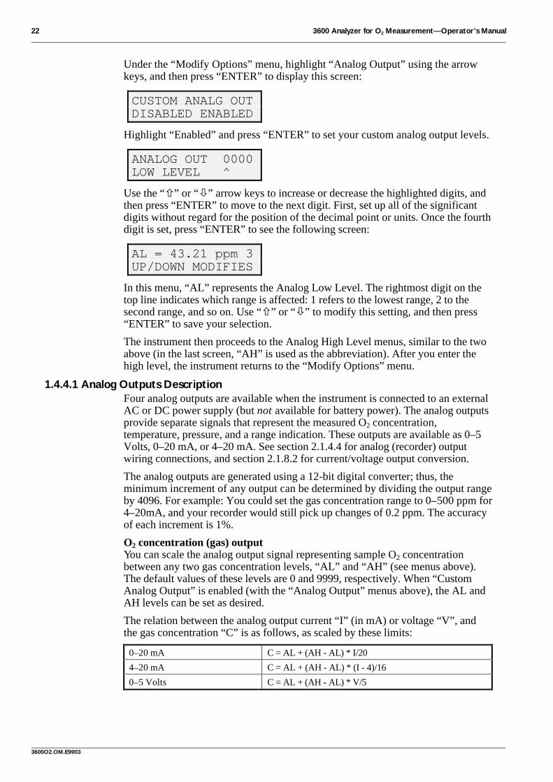
Under the “Modify Options” menu, highlight “Analog Output” using the arrowkeys, and then press “ENTER” to display this screen:
CUSTOM ANALG OUTDISABLED ENABLED
Highlight “Enabled” and press “ENTER” to set your custom analog output levels.
ANALOG OUT 0000LOW LEVEL ^
Use the “ñ” or “ò” arrow keys to increase or decrease the highlighted digits, andthen press “ENTER” to move to the next digit. First, set up all of the significantdigits without regard for the position of the decimal point or units. Once the fourthdigit is set, press “ENTER” to see the following screen:
AL = 43.21 ppm 3UP/DOWN MODIFIES
In this menu, “AL” represents the Analog Low Level. The rightmost digit on thetop line indicates which range is affected: 1 refers to the lowest range, 2 to thesecond range, and so on. Use “ñ” or “ò” to modify this setting, and then press“ENTER” to save your selection.
The instrument then proceeds to the Analog High Level menus, similar to the twoabove (in the last screen, “AH” is used as the abbreviation). After you enter thehigh level, the instrument returns to the “Modify Options” menu.
1.4.4.1 Analog Outputs DescriptionFour analog outputs are available when the instrument is connected to an externalAC or DC power supply (but not available for battery power). The analog outputsprovide separate signals that represent the measured O2 concentration,temperature, pressure, and a range indication. These outputs are available as 0–5Volts, 0–20 mA, or 4–20 mA. See section 2.1.4.4 for analog (recorder) outputwiring connections, and section 2.1.8.2 for current/voltage output conversion.
The analog outputs are generated using a 12-bit digital converter; thus, theminimum increment of any output can be determined by dividing the output rangeby 4096. For example: You could set the gas concentration range to 0–500 ppm for4–20mA, and your recorder would still pick up changes of 0.2 ppm. The accuracyof each increment is 1%.
O2 concentration (gas) outputYou can scale the analog output signal representing sample O2 concentrationbetween any two gas concentration levels, “AL” and “AH” (see menus above).The default values of these levels are 0 and 9999, respectively. When “CustomAnalog Output” is enabled (with the “Analog Output” menus above), the AL andAH levels can be set as desired.
The relation between the analog output current “I” (in mA) or voltage “V”, andthe gas concentration “C” is as follows, as scaled by these limits:
0–20 mA C = AL + (AH - AL) * I/20
4–20 mA C = AL + (AH - AL) * (I - 4)/16
0–5 Volts C = AL + (AH - AL) * V/5
3600 Analyzer for O2 Measurement—Operator’s Manual 23
3600O2.OM.E9903
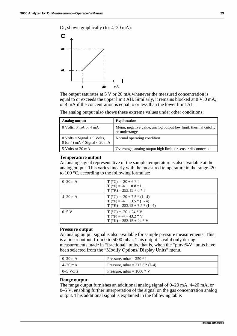
Or, shown graphically (for 4–20 mA):
The output saturates at 5 V or 20 mA whenever the measured concentration isequal to or exceeds the upper limit AH. Similarly, it remains blocked at 0 V, 0 mA,or 4 mA if the concentration is equal to or less than the lower limit AL.
The analog output also shows these extreme values under other conditions:
Analog output Explanation
0 Volts, 0 mA or 4 mA Menu, negative value, analog output low limit, thermal cutoff,or underrange
0 Volts < Signal < 5 Volts,0 (or 4) mA < Signal < 20 mA
Normal operating condition
5 Volts or 20 mA Overrange, analog output high limit, or sensor disconnected
Temperature outputAn analog signal representative of the sample temperature is also available at theanalog output. This varies linearly with the measured temperature in the range -20to 100 °C, according to the following formulae:
0–20 mA T (°C) = -20 + 6 * IT (°F) = -4 + 10.8 * IT (°K) = 253.15 + 6 * I
4–20 mA T (°C) = -20 + 7.5 * (I - 4)T (°F) = -4 + 13.5 * (I - 4)T (°K) = 253.15 + 7.5 * (I - 4)
0–5 V T (°C) = -20 + 24 * VT (°F) = -4 + 43.2 * VT (°K) = 253.15 + 24 * V
Pressure outputAn analog output signal is also available for sample pressure measurements. Thisis a linear output, from 0 to 5000 mbar. This output is valid only duringmeasurements made in “fractional” units, that is, when the “pmv:%V” units havebeen selected from the “Modify Options/ Display Units” menu.
0–20 mA Pressure, mbar = 250 * I
4–20 mA Pressure, mbar = 312.5 * (I–4)
0–5 Volts Pressure, mbar = 1000 * V
Range outputThe range output furnishes an additional analog signal of 0–20 mA, 4–20 mA, or0–5 V, enabling further interpretation of the signal on the gas concentration analogoutput. This additional signal is explained in the following table:

24 3600 Analyzer for O2 Measurement—Operator’s Manual
3600O2.OM.E9903
Range Output Explanation0–5V 0–20mA 4–20mA
0 0 4 Overrange, thermal cutoff, out of bounds
0.5 2 5.6 Lowest range
1 4 7.2 2nd range
1.5 6 8.8 3rd range
2 8 10.4 Not used
2.5 10 12 Not used
3 12 13.6 Not used
3.5 14 15.2 Custom analog output
4 16 16.8 Negative O2 signal
4.5 18 18.4 Menu (during operations under “modify options” or “calibrate”)
5 20 20 Sensor disconnected (“Check the Sensor” message appears)
Note: The range analog output is replaced by the oxygen measurement output in certain instrumentmodels, providing two equivalent gas output signals for control applications. These models aredenoted by “2 gas” in the Instrument Configurations list, section 3).
1.4.5 Serial OutputIf you use the instrument’s RS-232 interface for connection to a serial printer,monitor, or computer, highlight “Serial Output” under the “Modify Options”menu and press “ENTER” to bring up the following screen:
RS-232AUTO MANUAL
When “Auto” is selected, the RS-232 interface will output a three-line displayevery four seconds, showing gas concentration, sample temperature, and externalpressure. (The external pressure “value” will be present even if no such externalpressure sensor is connected.)
The “Manual” RS-232 output permits you to send just one set of measurements—gas, temperature, and external pressure—to a device at one time. Once enabled,you may send this information to a printer or other computer while the instrumentis in “Measurement” mode by pressing “ENTER”.
For RS-232 wiring instructions, see section 2.1.4.3. Pertinent communicationsparameters are: Baud rate: 9600. Stop Bit: 1. 8 Data Bits. Parity: None.
Orbisphere offers a data logging program (model 32680.E) running underWindows® to store this information. See section 1.7 for operating instructions.
This connection also can be used with a personal computer equipped with theWindows 3.1 “Terminal” program, the Windows 95/98 “HyperTerminal” program,or various third-party communications software such as ProComm or Crosstalk.
1.4.6 Salinity and Chlorinity AdjustmentsIf you want to inform the instrument of high salinity or chlorinity conditions thatcould otherwise affect oxygen measurement, a corrective menu is available.Pressing “ENTER” when “Salinity” is blinking under the “Modify Options” menudisplays this screen:
SAL. CORRECTIONDISABLED ENABLED
Note that both chlorinity and salinity are covered in this menu. Press “ENTER”when “Enabled” is blinking, and this screen appears:

3600 Analyzer for O2 Measurement—Operator’s Manual 25
3600O2.OM.E9903
SELECT UNITS g/lCHLORIN. SALIN.
Pressing “ENTER” for either one of these possibilities gives you the opportunityto enter expected salinity or chlorinity in a screen like this:
SALINITY 000.0MAX 54 g/l
The maximum chlorinity value, 30 grams per liter, is also displayed on its screen.
1.4.7 H2 Compensation Option (Model 32646.E)As mentioned in the calibration section (section 1.3.3.5), an option is available tocompensate for the presence of high H2 levels in samples. If this option (model32646.E) has been installed on your system, you may highlight “H2Compensation” under “Modify Options” and press “ENTER” to see this screen:
H2 COMPENSATIONDISABLED ENABLED
“Enabling” this option leads to another menu, where you are asked to enterexpected partial pressure levels of H2 in the sample:
H2 PRESSURE 0000 (MEAS)mbar ^
(The “(MEAS)” message helps to distinguish this menu from a similar-lookingmenu available in the “Calibration Pure Hydrogen” routine.)
Once “H2 Compensation” has been enabled, the oxygen sensor calibration mustthen be performed to assure accurate measurements.
1.4.8 Self DiagnosticsThis routine is helpful when you suspect a system malfunction, or if you simplywish to confirm that the system is in good working order.
Press “ENTER” when “Self Diagnostics” is flashing under “Modify Options” tobring up this screen:
DIAGNOSTIC TOOLSSENSOR KEYBOARD
The complete list of options includes “Sensor”, “Keyboard”, and “Memory”.
The “Sensor” diagnostics menu, as shown below, displays the current generated atthe sensor, in nanoamperes.
CURRENT 12.34 nA
This is useful when trying to identify a problem with an Orbisphere servicerepresentative either on-site or over the telephone. A table listing the expectedoxygen sensor currents is provided in section 3. Note that the sensor currentshould never exceed 35 µA; thus, for two of the listed membranes (models 2952Aand 29552A), you must check the sensor current in air, not in pure oxygen.
The “Keyboard” diagnostics can identify whether the front panel switches areworking properly. You will first see this menu:

26 3600 Analyzer for O2 Measurement—Operator’s Manual
3600O2.OM.E9903
WHICH MODE?MODE 0 MODE 1
“Mode 0” offers a test of the “ñ” and “ò” keys in “continuous” mode. Holddown either one of those keys, and check to see if the word “UP” or “DOWN”(respectively) flashes as the key is depressed.
“Mode 1” tests the “ñ”, “ò”, and “ENTER” keys in “latched” mode. Press one ofthose keys individually and release; the LCD should continue to flash thecorresponding word. Pressing “ESC” releases you from this test.
The “Memory” diagnostics uses the RS-232 output to download informationabout your instrument to a printer or other data acquisition device. While nothingwill appear on the LCD for this test, the information will be downloaded instantly.The information will appear at the RS-232 output as hexadecimal code, and will beof use to an Orbisphere representative to check whether your instrument has beenproperly configured.
1.4.9 Rolling AverageThe “Rolling Average” feature causes the O2 concentrations to be averaged oversuccessive measurement cycles for display or output. It suppresses sharp peaksand troughs caused by pressure shocks, electrical spikes, flow variations etc., whileretaining reasonably fast response to real concentration changes.
Press “ENTER” when “Rolling Average” is flashing under the “Modify Options”menu to display the following menu.
ROLLING AVERAGEDISABLED 3 5 7 9
You can choose to disable the rolling average, or enable the feature for averagingover 3, 5, 7, or 9 successive measurement cycles.
A cycle is completed in one second for the LCD and analog outputs. For example,choosing “5” lets you see the measurement displayed, or output, as an average offive measurements made in as many seconds, updated every five seconds.
For the RS-232 digital output, a cycle is completed in four seconds. Thus, in thisexample, choosing “5” would give you an average of five measurements made in20 seconds, and updated every 20 seconds.
1.4.10 Gas To Measure, CO2/H2S InsensitivityActivating this menu allows you first to confirm that your instrument is configuredfor O2 measurement, and then to activate either (but not both!) the “CO2Insensitive” or “H2S Insensitive” instrument configurations.
Pressing “ENTER” while “Gas” is flashing under “Modify Options” first revealsthe “Gas to Measure” menu. You should see “O2” displayed. (If not, contact yourOrbisphere representative for appropriate service.)
Then press “ENTER” to display this menu:
CO2 INSENSITIVENO YES
This is of interest in carbonated samples where high levels of carbon dioxidewould otherwise interfere with accurate O2 measurement. Pressing “ENTER”when “YES” is flashing will automatically return you to the “Modify Options”menu. If you choose “NO”, you are given the opportunity to switch theinstrument to “H2S Insensitive” mode:

3600 Analyzer for O2 Measurement—Operator’s Manual 27
3600O2.OM.E9903
H2S INSENSITIVENO YES
Note that operating in this mode requires a different sensor electrolyte, model2961, to be used in place of the standard electrolyte. It is supplied in apharmaceutical-type bottle with a septum that must be punctured and drawn outwith the syringe supplied with your recharge kit. The instrument reminds you ofthis requirement by displaying a message “Changed Electrolyte?” which will flashfor five seconds after you have answered “YES” to this option.
Also, note that when using this mode your system will experience a markedsensitivity loss, about 50 times greater levels of minimum detectability. That is, ifyour membrane listed in section 3 gave a lower limit of, say, 1 ppm, the H2SInsensitive mode would allow you to measure down to only 50 ppm.
1.4.11 Membrane SelectionShould you need to either confirm your present choice of membrane or selectanother, highlight “Membrane” under the “Modify Options” menu and press“ENTER”. This screen appears:
SELECT MEMBRANE29552 2956 2958
The complete list of membranes available is: 2956, 2958, 29552, 2952, 2995, 2935,and 29521. Highlight the membrane model number used on your sensor, thenpress “ENTER” to activate your selection. Membrane characteristics, includingrecommended flow rates, are listed in section 3.1.
Note: If you select any membrane (even if you reselect the same membrane andpress “ENTER”), you must re-calibrate the sensor, as described in section 1.3.3.

28 3600 Analyzer for O2 Measurement—Operator’s Manual
3600O2.OM.E9903
1.5 Maintenance (Sensor Service)Normally only the sensor requires service. If the indicating instrument is properlyconnected, handled with reasonable care and kept clean, it should give you nomechanical or electrical problems.
For the sensor, membrane wear and chemical reactions require that a specificmaintenance procedure should be performed from time to time. We cannot dictatea specific maintenance schedule for your application, since operating conditionsvary considerably. However, experience should make the intervals apparent, usingthe guidelines below.
Locate the cylindrical, black plastic base that is supplied with the sensor. The basescrews into the sensor at the bottom, placing the sensor in a secure, uprightposition and using an O-ring to seal the LEMO-10 connector from moisture. (Or,your Orbisphere representative may have supplied a larger, two-piece black plasticstand, model M26-5500, also designed for this purpose.)
The sensor service procedure is as follows (you may also refer to the Orbisphereposter “The ABC of Sensor Service” for further illustration of this procedure).
1.5.1 When to Perform a Sensor ServiceYou will know it is time when you experience:
• difficulties with calibration,
• an unusually long stabilization time, either with the sensor exposed to an air-saturated medium or to changing oxygen concentration conditions, or
• “noisy” or drifting signals under what you believe to be constant oxygenconcentration conditions.
1.5.2 Remove Sensor from SampleWhen you remove a sensor from either a flow chamber or sensor socket, take carethat no hazard will be created by the absence of the sensor. (In particular, whenusing a sensor socket to measure in liquid samples, make sure to drain all liquidfrom the pipe.)
Remove the sensor cable by unscrewing the LEMO connector at the end of thesensor handle. Then hold the sensor handle in one hand, and carefully unscrew thecollar and pull the sensor out of its socket or out of the flow chamber.
Place the sensor in its plastic base, screwing it down securely but not tight enoughto strip the plastic threads. An O-ring in the base provides a watertight seal for theLEMO-10 connector of the sensor.
1.5.3 Prepare Sensor for CleaningCarefully unscrew the protection cap, using the metaltool supplied with your recharge kit. Take care not tolose the grill and washers inside. The protection capincludes washers, and for some applications, a Dacronmesh and a stainless steel grill—if you are unfamiliarwith these components, check the exploded sensordiagram in section 1.6.1.
You may want to check back to the sensor diagram insection 1.2, and note the order of sensor headcomponents shown:
• Membrane holding ring;
• Membrane; and
• The sensor’s membrane support.
Removingprotection cap
3600 Analyzer for O2 Measurement—Operator’s Manual 29
3600O2.OM.E9903
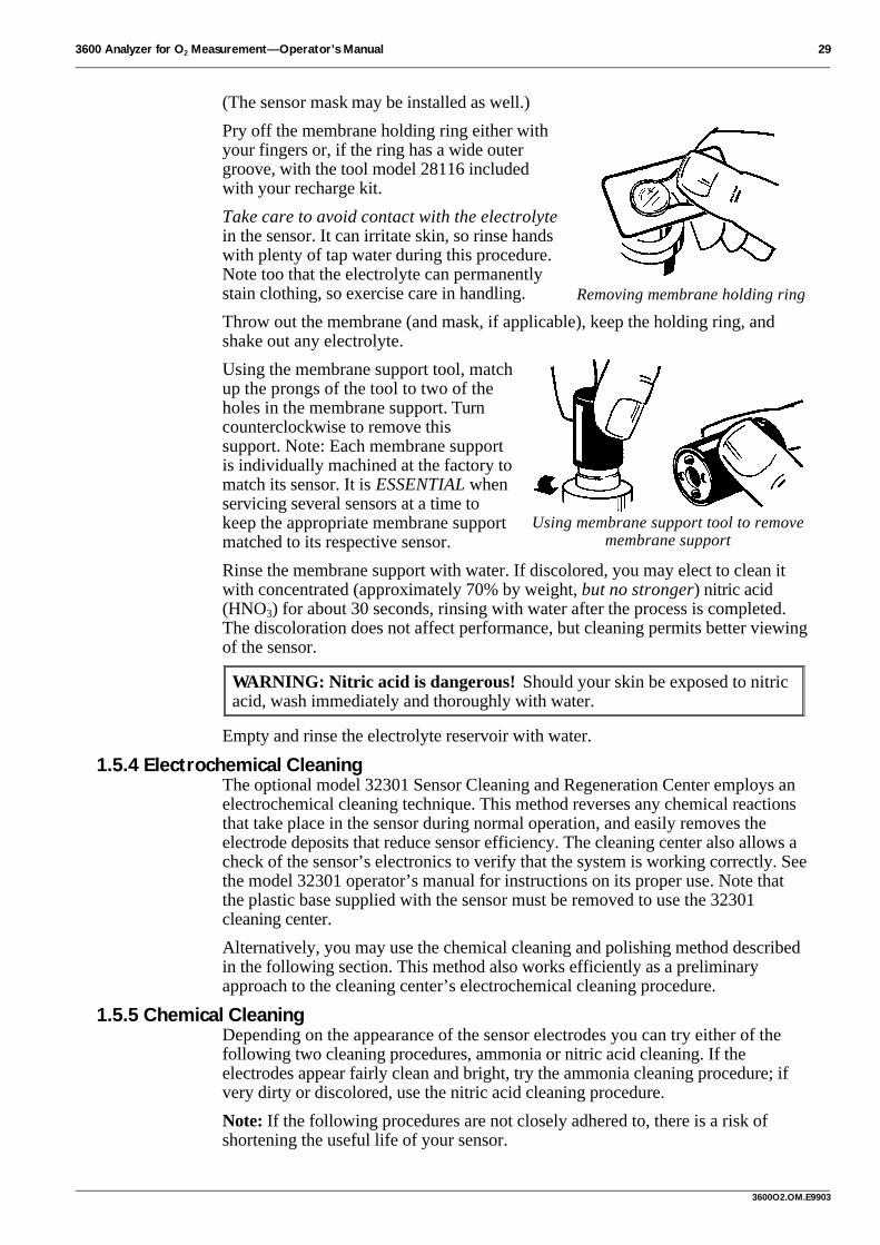
(The sensor mask may be installed as well.)
Pry off the membrane holding ring either withyour fingers or, if the ring has a wide outergroove, with the tool model 28116 includedwith your recharge kit.
Take care to avoid contact with the electrolytein the sensor. It can irritate skin, so rinse handswith plenty of tap water during this procedure.Note too that the electrolyte can permanentlystain clothing, so exercise care in handling.
Throw out the membrane (and mask, if applicable), keep the holding ring, andshake out any electrolyte.
Using the membrane support tool, matchup the prongs of the tool to two of theholes in the membrane support. Turncounterclockwise to remove thissupport. Note: Each membrane supportis individually machined at the factory tomatch its sensor. It is ESSENTIAL whenservicing several sensors at a time tokeep the appropriate membrane supportmatched to its respective sensor.
Rinse the membrane support with water. If discolored, you may elect to clean itwith concentrated (approximately 70% by weight, but no stronger) nitric acid(HNO3) for about 30 seconds, rinsing with water after the process is completed.The discoloration does not affect performance, but cleaning permits better viewingof the sensor.
WARNING: Nitric acid is dangerous! Should your skin be exposed to nitricacid, wash immediately and thoroughly with water.
Empty and rinse the electrolyte reservoir with water.
1.5.4 Electrochemical CleaningThe optional model 32301 Sensor Cleaning and Regeneration Center employs anelectrochemical cleaning technique. This method reverses any chemical reactionsthat take place in the sensor during normal operation, and easily removes theelectrode deposits that reduce sensor efficiency. The cleaning center also allows acheck of the sensor’s electronics to verify that the system is working correctly. Seethe model 32301 operator’s manual for instructions on its proper use. Note thatthe plastic base supplied with the sensor must be removed to use the 32301cleaning center.
Alternatively, you may use the chemical cleaning and polishing method describedin the following section. This method also works efficiently as a preliminaryapproach to the cleaning center’s electrochemical cleaning procedure.
1.5.5 Chemical CleaningDepending on the appearance of the sensor electrodes you can try either of thefollowing two cleaning procedures, ammonia or nitric acid cleaning. If theelectrodes appear fairly clean and bright, try the ammonia cleaning procedure; ifvery dirty or discolored, use the nitric acid cleaning procedure.
Note: If the following procedures are not closely adhered to, there is a risk ofshortening the useful life of your sensor.
Removing membrane holding ring
Using membrane support tool to removemembrane support

30 3600 Analyzer for O2 Measurement—Operator’s Manual
3600O2.OM.E9903
1.5.5.1 Ammonia CleaningFill the sensor electrolyte reservoir with a solution of 25% by weight ammoniumhydroxide (NH4OH) in water and leave for 10 minutes. Then rinse with water forat least one minute.
Inspect the sensor head. The counter electrode (anode) should be a uniform,silver-white color. If it is clean, rinse the electrolyte reservoir with water for a fullminute. However, if the sensor head is still discolored, repeat the above procedure.
If three consecutive cleanings do not produce the desired result, you should usethe nitric acid cleaning procedure described below.
1.5.5.2 Nitric Acid CleaningRinse out the sensor head with water and proceed as follows.
Place concentrated (up toapproximately 70% by weight,but no stronger) nitric acid(HNO3) in the sensorelectrolyte reservoir, justenough to cover the anodeonly, not the cathode.
Leave the acid in place for nolonger than 5 seconds. Thenempty out the acid and rinsethoroughly with water.
WARNING: Nitric acid is dangerous! Should your skin be exposed to nitricacid, wash immediately and thoroughly with water.
If the anode is still not completely clean, alternate between nitric acid andammonium hydroxide cleanings.
1.5.6 Polish Sensor FaceAfter cleaning, screw on the membranesupport, “finger tight”, using itsmounting tool. (Note: The support hasone smooth side with a groove, and oneside that is raised in the center, asshown. Make sure the smooth side witha groove faces out when installed.)
Because there is a danger of overtightening the plastic threads, the sensorhas a safety feature that causes themembrane support to “skip” its threadsharmlessly if over tightened. Should this occur, re-tighten with less force.
Place the polishing clothin its dish on a flatsurface and shake a littlepolishing powder ontothe cloth, addingenough clean water tomake a loose, waterymixture.
Holding the sensorvertically, and using a
Using nitric acid to clean sensor electrodeNote: Always use protective gloves and goggles!
Tightening membrane support (note
proper orientation, grooved side “up”)
Mixing polishing powder andwater on polishing cloth
Polishing sensor withcircular motion

3600 Analyzer for O2 Measurement—Operator’s Manual 31
3600O2.OM.E9903
circular motion, polish the sensor face for at least 30 seconds, until the goldcathode is clean and shiny. (You may need to repeat this step several times.) Makesure to avoid skin contact with the polishing cloth; keep it free of dust and grease.
Remove the membrane support with its tool, as shown above in section 1.5.3(taking care not to mix the membrane support with others in case you areservicing several sensors at once).Thoroughly rinse the membranesupport and the sensor to remove alltraces of polishing powder.
Inspect the groove between the goldcathode and the guard ring electrodefor polishing powder deposits. Youmay want to rinse away these depositswith a strong jet of distilled water.
1.5.7 Replace MembraneReplace the membrane support with its tool—remember, only “finger tight”—andmake sure that the side with a groove faces out when installed.
Fill the sensor head with model 2959 electrolytethrough the membrane support, using the syringe fromyour recharge kit. It helps to tilt the sensor slightly,filling the head from the lowest of the four holes facingyou. Do this slowly, forcing the air out through the tophole.
Continue filling, returning the sensor to vertical, untilan overflow of electrolyte adheres to the surface of thesensor face.
Take out the black plastic membrane mounting tool included with your rechargekit. You will note that the tool is in two parts, a plunger and a hollow, cylindricalguide.
Place the cylindrical guide of themounting tool over the sensor head,around the sensing face so that itrests on the sensor shoulder.
Place a membrane on the sensorface and check that it lies flat and iscentered. To avoid air bubbles,introduce the membrane at an angleinto the guide.
If you are using a sensor mask,place it directly on top of the membrane, in the guide.
Now, pick up themounting tool’s plunger.Slide your membraneholding ring onto thebeveled edge of theplunger.
Insert the plunger, withholding ring, into theopen hole of the guide,and push down to a stop.
Using a jet of distilled water to clean groovebetween cathode and guard ring electrode
Filling with electrolyte
Placing guide onsensor
Placing membrane onsensor face
Placing membrane holdingring on plunger
Inserting plunger intoguide

32 3600 Analyzer for O2 Measurement—Operator’s Manual
3600O2.OM.E9903
The membrane is mounted.
Remove both parts of the membrane mounting tool.
Inspect the membrane holding ring to be sure that it’sproperly seated and pushed in all the way, and makesure that the membrane is smooth. If not, you may beable to complete the process by pushing down withyour fingers. If this does not work, replace themembrane.
Note that the O-ring that forms a seal betweenholding ring and sensor should be replaced if theholding ring turns easily.
Check that there are no air bubbles beneath the surface of the membrane. If thereare, you must replace the membrane.
Wash excess electrolyte off the sensor and wipe dry. Then unscrew the blackplastic base, taking care not to get the sensor’s LEMO-10 connector wet.
1.5.8 Put Sensor Back into ServiceRe-connect the sensor to its cable, by screwing in the cable connector to the rearof the sensor.
Then replace the screw-on protection cap. Theprotection cap may include washers only, or it mayinclude Dacron mesh or a water separation filter, and astainless steel grille. Please check that thesecomponents are clean and dry before installation. Ifyou are unfamiliar with these components’ assemblyorder, check the diagram shown in section 1.6.1. Theprotection cap should be tightened finger tight, andthen secured with an extra 1/8 to 1/4 turn with its metalwrench, included with your recharge kit.
After giving the membrane at least 30 minutes to relax,calibrate the system (see section 1.3.3).
Once the sensor has been calibrated, place the sensor back into the sample, usingits collar to secure it into place if appropriate. Your sensor should be ready to beginmaking measurements.
1.5.9 Shutting Down the SystemDuring a short shut-down period (such as weekends), the sensor can be left in itsflow chamber or sensor socket.
If this inactive period is likely to last a long time, you should remove the sensorfrom its flow chamber or sensor socket.
If you expect not to use your sensor for more than a few months, you shouldclean the sensor, as instructed in sections 1.5.1 to 1.5.8, and store it “dry”, withoutelectrolyte, with the calibration cap in place for protection.
Since the instrument has a non-volatile memory, important parameters will remainmemorized even when the instrument is switched off.
Pushing plunger to finishmembrane mounting.
Replacingprotection cap

3600 Analyzer for O2 Measurement—Operator’s Manual 33
3600O2.OM.E9903
1.5.10 TroubleshootingOrbisphere analyzers are fully factory tested before shipment. Provided they havebeen handled properly and are correctly installed, they should be trouble-free.
Here is a list of possible troubles caused by poor handling or identifiableinstallation conditions. If you cannot find a solution here, contact your authorizedOrbisphere service technician.
Problem Probable Cause Possible Solution
Sensor won’tcalibrate, even afterthorough servicing
Repeated calibrationsgo beyond “expectedlimits” of instrument
Re-select membrane from“Options/Membrane” menu, section 1.4.11.Then, recalibrate the sensor.
Instrument’s internalbarometric pressuresensor needs calibration
Recalibrate using “Calibrate/Barom.Pressure” menu, section 1.3.3.1. Checkagainst reliable barometer. Do not correct forsea level!
H2S insensitivity optionunnecessarily enabled
Unless you need “H2S insensitive” (whichuses different electrolyte) disable from“Options/Gas” menu, section 1.4.10.
No analog outputsignal (portableinstrument)
Portable instrumentrequires mains powerfor analog output
Connect to appropriate mains power.
“0000” O2 levelsdisplayed
“XXXX” selected forunit lowest range
Choose “X.XXX, XX.XX or XXX.X” from“Options/Display Units” menu, section 1.4.1.
Shorter-than-expectedsensor operation (inrelatively high DO2)
High O2 concentrationsrequire more work fromelectrochemical sensor
Shut off analyzer when not needed.
Unexpected/incorrectDO2 readings
Sample air leak Set flow rate to 100 ml/min; wait until stable.Slowly increase to 200 ml/min.If a significant DO2 decrease is displayed, asample air leak is likely.
High residual current Place sensor in dearated sample; wait for lowreading; check concentration against lowmeasurement limit (see tables in section 3).If concentration is significantly higher thanlow limit, try a sensor service, section 1.5.1.
Instrument and“moca3600” PCprogram areoperational, but donot work together(i.e. no data transfer)
Improper PC-to-instrument connection
Confirm that:• “Options/Serial Output” is Enabled, section
1.4.5;• All 9 pins are available, if using a 25-to-9
pin converter at the PC;• There are no PC COM port/IRQ conflicts.
Alarm relays won’toperate properly
Normally open /normally closed statereversed
Both NO and NC outputs available; confirmwiring to LEMO (portable instrument) orterminal block (process instrument)

34 3600 Analyzer for O2 Measurement—Operator’s Manual
3600O2.OM.E9903
1.6 Spare PartsYour recharge kit should contain sufficient material for several years of sensorservicing. However, it will need to be replenished in time. What follows arematerials you will be likely to require. Be sure to mention the model number anditem description when ordering. (Note that there is an exploded sensor diagram inthe following section, with protection cap components identified.)
Model number Description
28083 LEMO-6 pin connector28084 LEMO-10 female connector for extension cable28085 LEMO-10 male connector for extension cables28088 LEMO-10 connector for panel mount28113 Membrane mounting tool (2 pcs)28210 LEMO-8 pin connector29006.0 EPDM O-rings for 32001 flow chamber29501 Sensor socket for welding to SS pipe2959 Electrolyte for sensor2961 Electrolyte for sensor, H2S insensitive2978 Polishing powder and cloth32001.010 Flow chamber, SS, 6-mm fittings, EPDM O-rings32001.011 Flow chamber, SS, ¼-in. fittings, EPDM O-rings32001.030 Flow chamber, Delrin, 6-mm fittings, EPDM O-rings32001.031 Flow chamber, Delrin, ¼-in. fittings, EPDM O-rings32002.010 Multi-parameter flow chamber, SS, 6-mm connections, EPDM O-rings32002.011 Multi-parameter flow chamber, SS, ¼-in. connections, EPDM O-rings32205 Sensor support (base) for 31xxx sensors32537 RS-232 cable, with LEMO-6 and 9-pin D-type connectors32701 Recharge kit, 2935A membrane32702 Recharge kit, 2952A membrane32703 Recharge kit, 2956A membrane32704 Recharge kit, 2958A membrane32705 Recharge kit, 29521A membrane32706 Recharge kit, 29552 membrane32707 Recharge kit, 2995A membrane32750 Battery, type G-1600CS, nickel-cadmium, 1.6 A/hr, 5 x 1.2 V cells
Contents of Recharge Kit:Model number Description
2956A, 2952A, 29552A, 2958A,2995A, 2935A, 29521A
Membranes (alternatives available)
29026A, 29027A Masks (optional)2959 Electrolyte2978 Polishing powder and cloth29228, 29229 Membrane holding ring (model depends on membrane)29039.0 EPDM O-ring28504 Tool for tightening protection cap28116 Tool for removing membrane holding ring28114 Tool for removing membrane support28113 Membrane mounting tool
Syringe and Tweezers

3600 Analyzer for O2 Measurement—Operator’s Manual 35
3600O2.OM.E9903
1.6.1 Oxygen Sensor and Protection Cap DiagramAll sensors include a screw-on protection cap, available in one of threeconfigurations. The standard protection cap, model 29104, provides improvedmembrane sealing. The other configurations, for “Moist Gases” (model 29107)and for “Liquids and Dry Gas Samples” (model 29106) also include a stainlesssteel grill and either a Dacron mesh or water separation filter. The grill prevents themembrane from lifting under such harsh conditions as high sample pressures, ormeasuring in carbonated samples.
Oxygen sensor with screw-on protection cap components for different applications

36 3600 Analyzer for O2 Measurement—Operator’s Manual
3600O2.OM.E9903
Position Reorder Number Description
1 LEMO-10 connector
2 32502.mm (3600 series)32506.03 (3600M series)
Sensor cable, 2 connectors (“mm” = length, standardlength 3 meters)
3 28104 Sensor collar, stainless steel
4 Sensor handle
5 29039.0 Sensor head O-ring (see also Kits below)
6 Sensor head
7 2952A, 2956A, 2958A,29552A, 2995A,2935A,29521A
Membrane (model depends on application)
8 29026A29027A
Tedlar maskSaran mask
9 29228
29229
29231
Membrane holding ring, for membranes2956A, 2952A, 2995A, 2935AMembrane holding ring, membrane 29552 or 2958A, orfor combination of mask (29026A or 29027A) andmembrane 2956A, 2952A, 2995A or 2935AMembrane holding ring for membrane 29521A
10 28003 Silicone washer (see also Kits below)
11 29049 Dacron mesh (see also Kits below)
12 29060 0.20 mm grill (see also Kits below)
13 28002 Tefzel washers (see also Kits below)
14 29104 Standard protection cap
15 28504 Wrench for protection cap
16 29031A Water separation filter (see also Kits below)
17 29107 Protection cap for moist gases
18 29106 Protection cap for liquids and dry gases(Note that the Tefzel washers are clearer and thinner than the Silicone washers are, and twice asmany Tefzel washers are supplied in a kit.)
Protection Cap Kits Available:29046 28002 washers, 29060 grill, 29049 meshes, 28003 washers, and 29039.0 O-ring for
protection cap 29106
29054 28002 washers, 28003 washers, and 29039.0 O-ring for protection cap 2910429063 28002 washers, 29060 grill, 28003 washers, 29031A, water separation filters, and
29039.0 O-ring for protection cap 29107

3600 Analyzer for O2 Measurement—Operator’s Manual 37
3600O2.OM.E9903
1.7 Data Acquisition SoftwareThe 3600 instrument can be used as a PC data acquisition device through theWindows®-compatible “moca3600” program, available as model 32680.E.
The moca3600 program uses the instrument’s RS-232 connection to set up a tableof measurement information including gas concentration, temperature, and time.
The program can use any available serial port on your computer. It may benecessary to run an independent utility on your PC in order to designate such a“COM” port. The port must be set for the following communication parameters:
Baud rate: 9600; Data bits: 8; Stop Bit: 1; Start Bit: 0;Parity: None; Flow control: None
1.7.1 Program SetupFirst, copy the contents of the floppy disk (designated here as drive “A”) ontoyour hard drive (designated here as drive “C”). About 80 kilobytes of hard diskspace is needed. (A “MOCA3600.INI” file is created in the C:\WINDOWS directory bythe moca3600 program to save user changes to default program settings.)
1.7.1.1 Windows 3.1 SetupTo do this using Windows 3.1, place the floppy disk in its drive and choose File,Copy from the File Manager menu to bring up this dialog box:
Type the copy command as shown above and choose OK or press ENTER. A boxappears, stating “Directory C:\MOCA3600 does not exist. Do you want to createit?” Choose YES or press ENTER to confirm that you do.
To set up the program in conventional Windows fashion (i.e., where one candouble-click on an icon to start the program), switch to Program Manager. Thinkabout which program group you want the moca3600 program icon to appear in,and click once within that program group.
Select File, New, Program Item. A box appears:
Complete the instructions as shown. Click on OK when finished, and a“MOCA3600” program icon will appear on-screen.
1.7.1.2 Windows 95 SetupTo setup the program using Windows 95, first place the floppy disk in its drive.Now, open the Windows Explorer and copy the moca3600 program, as follows.
1. In the Explorer’s Folders list, click on the (C:) drive icon.
2. In the Explorer File menu, point to New, and then click on Folder.
3. Type “Moca3600” for the folder name, and press ENTER.

38 3600 Analyzer for O2 Measurement—Operator’s Manual
3600O2.OM.E9903
(Note: You can change the folder name at any time by clicking on the folder iconwith the right mouse button, selecting the Rename command, and thenretyping the name.)
4. In the Folders list, click on the Floppy (A:) drive icon.
5. Using the left mouse button, click on the Moca3600.exe icon and drag it to theMoca3600 folder just created above, and then release the button. Themoca3600 program is now copied onto your hard drive.
Next, set up the moca3600 program for conventional Windows 95 access (i.e.,where you click on a Start menu entry to start the program), as follows.
1. In the Explorer’s Folders list, first click on the plus sign next to the Windowsfolder, then click on the plus sign next to the Start Menu folder.
2. Locate and click on the new Moca3600 folder icon in the Folders list.
3. Using the right mouse button, click and drag the Moca3600.exe icon to thePrograms folder (under the Start Menu folder), and then release the button.
4. Click the Create Shortcut(s) Here command on the menu displayed. Ashortcut icon is created in the Programs folder.
5. Click on the Programs folder icon in the Folders list.
6. To change the name of the shortcut icon (e.g., to remove the name “Shortcutto...”), use the right mouse button to click on the Shortcut icon, then click onthe Rename command.
7. Type in “Moca3600 Program” over the program name, and press ENTER.
To start the moca3600 program, just choose the Start, Programs menu and click onthe Moca3600 Program icon from the Programs list.
1.7.2 Menu OverviewThe moca3600 program main menus appear as follows:
The “File” menu includes typical Windows file management and printingfunctions.
The “Terminal” menu commences and ends the data acquisition process.
The “Export” menu permits the information to be copied to the WindowsClipboard, for pasting into other Windows programs.
The “Configuration” menu lets you customize the program for your application’srequirements.
1.7.3 Configuring the ProgramWith the instrument connected to your PC, and the sensor placed in a sample,start the moca3600 program and configure it for your data acquisition needs.
First, make sure the program knows which “COM” port will be used by your PCby choosing Communications from the Configuration menu. The following Serialport configuration box appears:

3600 Analyzer for O2 Measurement—Operator’s Manual 39
3600O2.OM.E9903
Next, check that you have set the acquisition rate to a convenient interval. Do thisby choosing Data Acquisition from the Configuration menu. This box appears:
The “All data” choice enables the program to accept measurements every fourseconds, the fastest rate available from the instrument. The longest interval is onehour. Choose OK when you have the rate you require.
Finally, make sure you have chosen the proper gas to measure from the GasSelection menu under Configuration.
1.7.4 Acquiring Data To commence data acquisition, while the instrument is making measurements,choose Go from the Terminal menu.
You can expect to see a running display like the following:
The number of samples in the buffer will continue to rise until you choose Endfrom the Terminal menu, or when the limit of 2,000 samples has been reached.

40 3600 Analyzer for O2 Measurement—Operator’s Manual
3600O2.OM.E9903
1.7.5 Printing, Copying, and Saving Data The File, Print command will place your list of values into a pre-formatted tabulartemplate, and send it to your printer via Windows. The program asks you to enter“Title” and “Author” information as follows. Note that the “Date” is fixed by youroperating system.
The resulting printed list will include this information on each page.
To copy this list to the Windows Clipboard, so that this information can be“pasted” into a spreadsheet, word processor or any other kind of Windowsprogram that accepts tabular text information, choose Export, To Clipboard.
To save this list as a text (“.txt”) file, capable of being recalled by the moca3600program or imported as a file into other Windows programs, choose File, Save As.A dialog box appears, with a space to fill in with an eight-letter name. (Theprogram automatically attaches a “.txt” suffix to these files.) If you have savedprevious files, a “grayed-out” list of these names appears as well. Typical toWindows programs, “Directories” and “Drives” boxes can be used to locate otherplaces to save (for example, on a floppy disk); you may also type the drive anddirectory yourself when saving the file.

3600 Analyzer for O2 Measurement—Operator’s Manual 41
3600O2.OM.E9903
1.8 Warranty InformationAll Orbisphere systems are warranted against defective materials andworkmanship for one year from the date of shipment. Our obligation is limited torepairing or replacing products of our manufacture which prove to be defectiveduring the warranty period and which are returned to the factory, transportationcharges prepaid. We are not liable for consequential charges. In case ofcomponents not of our manufacture, we grant only such warranty as we mayreceive from our suppliers. Repairs inside the sensor and indicating instrumentmust be performed by Orbisphere or its representatives.
The above warranty may therefore be rendered null and void in the event ofunauthorized opening. We reserve the right to make improvements to our productsat any time without incurring any liability to purchasers of earlier models.
1.8.1 About this ManualThe information in this manual has been carefully checked and is believed to beaccurate. However, Orbisphere assumes no responsibility for any inaccuracies thatmay be contained in this manual. In no event will Orbisphere be liable for direct,indirect, special, incidental, or consequential damages resulting from any defect oromission in this manual, even if advised of the possibility of such damages.
In the interest of continued product development, Orbisphere reserves the right tomake improvements in this manual and the products it describes at any time,without notice or obligation.

42 3600 Analyzer for O2 Measurement—Operator’s Manual
3600O2.OM.E9903
2. Installation GuidelinesThis section should provide you with all the necessary information to prepare forand install your instrument. Note that additional technical information is includedin section 3. If you still have any questions or encounter any difficulties, contactyour Orbisphere representative.
2.1 Indicating Instrument InstallationThe series 3600/3600M indicating instrument is available in several versions, whichallow different means of mounting, power input, and electrical signal connections.
2.1.1 Panel or 19-inch Rack Mount Instrument Installation2.1.1.1 Instrument Mounting
The standard panel mount instrument configuration is illustrated below.
3600/3600M indicating instrument, panel mount version
Note: Include at least 100mm additional rear clearance for cable protrusion.
You can use the model 32200 panel mount template as a guide for the necessarypanel cutting and drilling. To use, place the template where you wish to mount theinstrument, and mark the drill holes and cut lines. Your mounting hardwareincludes a drill bit; use it to drill the 5.4-mm holes required; then cut the 214.5-mmwide by 125.5-mm high panel hole.
Four self-clinching bolts secure the instrument to the panel. It is easiest to attachthe bottom two bolts first (tightening with the Allen key supplied), guide theinstrument into place, and then fix the top two bolts to finish the procedure. Oncetightened, the self-clinching bolts assure that one person can accomplish futureremoval of the instrument.
A retrofit panel mount (model 32201) is also available. This enables users ofexisting Orbisphere analyzers to replace their instruments with the 3600/3600Mseries, without additional drilling or panel cutting, as shown below.

3600 Analyzer for O2 Measurement—Operator’s Manual 43
3600O2.OM.E9903
3600/3600M indicating instrument, retrofit panel mount (model 32201)Note: Include at least 100mm additional rear clearance for cable protrusion.
The instrument can be mounted in a 19" rack, either one- or two-across in athree-height configuration, as shown:
3600/3600M indicating instrument, 19" rack mount version, one-across (model 32202)and two-across (model 32203) methodsNote: Include at least 100mm additional rear clearance for cable protrusion.
As with the panel mount configuration, four self-clinching bolt assemblies securethe instrument to the rack panel.

44 3600 Analyzer for O2 Measurement—Operator’s Manual
3600O2.OM.E9903
2.1.1.2 Power Input
The installation of a 3600 / 3600M instrument should only be performed bypersonnel specialized and authorized to work on electrical installations, inaccordance with relevant European and/or national regulations.
In accordance with safety standard EN 61010-1, it must be possible to disconnectthe power supply of a 3600 / 3600M instrument in its immediate vicinity.
While the instrument’s electronics are well shielded, it is still advisable to locatethe instrument as far as possible from any source of electromagnetic perturbation.
AC Power Input
AC power connections for panel or 19" rack mount instruments use a standarddetachable cable on the rear panel of the instrument.
For panel or 19" rack mount instruments, a power supply cable, type H05VV-F 3X 0.75 mm2, which is supplied with the instrument, must be used. The length ofthe cable should be three meters maximum and it should have a separable plug(with three connectors, L+N+PE), without a locking device, to mate with a socketoutlet in the building. The cable and the plug must conform to an appropriateEuropean or national standard.
10–30 VDC Power Input
10–30 VDC powered panel or 19" rack mount instruments have a male Binderconnector on their rear panel. It accepts DC power as follows:
Pin 1: DC ReturnPin 2: Earth (Chassis)Pin 3: Not connectedPin 4: 10–30 Volts DC
Male Binder receptacle, rear panel of instrument
The user must make the necessary power wiring connections, using the femaleBinder plug supplied with your system. User-supplied power cable can have anouter diameter between 5 and 8 mm.
To disassemble the plug, squeeze the two clips located in the middle of the plug(position “C” below). This reveals numbered wiring connections inside, to bematched one-to-one with the diagram above.
Female Binder plug, exploded view
2.1.1.3 Electrical Signal ConnectionsPanel or 19" rack mount instrument connections to the oxygen sensor andexternal pressure sensor use the pre-wired LEMO connectors on the rear panel ofthe instrument. The LEMO connector pin assignments are identified in section2.1.4, Instrument Connectors. Instructions for wiring the LEMO plugs are insection 2.1.6, LEMO Connector Assembly Instructions.
Connections for RS-232, recorder (analog) output, and alarm relays use thestainless steel watertight glands on the instrument rear panel. These connectionsmust be hard-wired to a terminal strip inside the instrument. Instructions forwiring these outputs through the cable glands are in section 2.1.7, Cable GlandWiring Instructions.

3600 Analyzer for O2 Measurement—Operator’s Manual 45
3600O2.OM.E9903
Requirements for these user-supplied cables are in section 2.1.5, User-suppliedCabling Requirements—note that you must ground each cable shield properly toassure proper operation.
3600/3600M indicating instrument rear panel, panel or 19" rack mount version, shownwith optional external pressure sensor input
To make any of these connections, you must remove the rear instrument panel.First, make sure the power supply is unplugged, and remove the front-panel key.Then place the instrument face-down and loosen the four 3-mm Allen-headscrews. Carefully pull off the rear panel, taking care not to disconnect any wires, toexpose the terminal strip wiring diagram label.
The model 3600 and the model 3600M series have different terminal strip wiringconnections. A wiring label inside the rear panel identifies each unit’s terminalstrip connections. Each of the following wiring descriptions identifies theappropriate terminal connections of each model.
3600 serieswiring label:
3600 seriesterminal strip:

46 3600 Analyzer for O2 Measurement—Operator’s Manual
3600O2.OM.E9903
3600M serieswiring label:
3600M seriesterminal strip:
As an example, to connect a recorder capable of accepting the instrument’s 0/4–20mA (or 0–5 V) analog output for gas concentration, take the live signal outputfrom position “J13.3” of the terminal strip; the return signal is connected toposition “J14.3” of the terminal strip.
2.1.2 Wall Mount Instrument Installation2.1.2.1 Instrument Mounting
The 3600 instrument is available as a wall mount version with the followingdimensions:
3600 indicating instrument, wall mount version, front view

3600 Analyzer for O2 Measurement—Operator’s Manual 47
3600O2.OM.E9903
3600 indicating instrument, wall mount version, bottom view
Note: Include at least 400 mm additional frontal clearance for front panel access, andat least 100 mm bottom clearance for cable protrusion.
2.1.2.2 Power Input
The installation of a 3600 instrument should only be performed by personnelspecialized and authorized to work on electrical installations, in accordance withrelevant European and/or national regulations.
In accordance with safety standard EN 61010-1, it must be possible to disconnectthe power supply of a 3600 instrument in its immediate vicinity.
While the instrument’s electronics are well shielded, it is still advisable to locatethe instrument as far as possible from any source of electromagnetic perturbation.
AC Power Input
AC power connections for wall mount instruments use the rightmost waterproofcable gland, and are wired according to a label inside the cabinet.
For wall mount instruments, a flexible cable of the recommended type H05VV-F 3X 0.75 mm2 should be used. The length of the cable should be three metersmaximum and it should have a separable plug (with three connectors, L+N+PE),without a locking device, to mate with a socket outlet in the building. The cableand the plug must conform to an appropriate European or national standard.
Three “FAST ON” 6.3-mm red, spade-type connectors are supplied with the wallmount instrument for wires measuring from 0.5–1 mm2.
1. Remove the exterior insulation of the cable for a length of about 50 mm.
2. Insert the cable through the rightmost cable gland.
3. Strip the wires for a length of about 8 mm.
4. Put a “FAST ON” (spade-type) connector on each of the 3 wires.
5. Put the live, neutral, and earth wires on the corresponding spade plugs of themains filter, as indicated on the label affixed to the bottom of the wall mountbox, opposite the filter.
6. Slide the cable farther through its cable gland until its external insulationpenetrates about 6 mm inside the measurement box, blocking the cable gland.

48 3600 Analyzer for O2 Measurement—Operator’s Manual
3600O2.OM.E9903
10–30 VDC Power Input
Connect the 10–30 VDC versions of wall mount instruments in a similar fashionas the AC-powered versions, above. Insert the power cable through the rightmostwaterproof cable gland, and wire according to the label inside the cabinet.
2.1.2.3 Electrical Signal ConnectionsWall mount instruments connections use the LEMO connectors and stainless steelwatertight glands at the bottom of the instrument housing (see wall mountinstrument bottom view illustration in section 2.1.2.1).
Connections from the instrument to the oxygen sensor and the external pressuresensor use the LEMO receptacles on the bottom of the instrument housing.
Connections for RS-232, recorder (analog) output, and alarm relays use thestainless steel watertight glands at the bottom of the instrument housing. Theseconnections must be hard-wired to a terminal block on a printed circuit board,located at the rear of the instrument, within the wall mount housing. A wiringdiagram label inside the housing identifies each unit’s terminal strip connections.To access this board, unlock the front panel of the wall mount unit with the keyprovided to expose the instrument electronics inside.
Make to disconnect power to the instrument before opening the frontpanel.
The connection board, number 1127.901 (this part number is printed on the loweredge of the card), contains the terminal block connections and a terminal block pinwiring label.
Connection board 1127.901, showing location of terminal blocks J5, J6, and J7
Instructions for wiring the analog recorder, alarms, and RS-232 outputs throughthe cable glands are in section 2.1.7, Cable Gland Wiring Instructions.Requirements for these user-supplied cables are in section 2.1.5, User-suppliedCabling Requirements. Note that you must ground each cable shield properly toassure proper operation.
2.1.3 Portable Instrument Installation2.1.3.1 Instrument Mounting
Series 3600 portable instruments require no permanent mounting or installation.Locate the instrument near the power source and the sensors.
2.1.3.2 Power Input
In accordance with safety standard EN 61010-1, it must be possible to disconnectthe power supply of a 3600 instrument in its immediate vicinity.
While the instrument’s electronics are well shielded, it is still advisable to locatethe instrument as far as possible from any source of electromagnetic perturbation.
AC Power Input
AC power connections for portable instruments use a standard detachable cableon the rear panel of the instrument.

3600 Analyzer for O2 Measurement—Operator’s Manual 49
3600O2.OM.E9903
For portable instruments, a power supply cable, type H05VV-F 3 X 0.75 mm2,which is supplied with the instrument, must be used. The length of the cableshould be three meters maximum and it should have a separable plug (with threeconnectors, L+N+PE), without a locking device, to mate with a socket outlet in thebuilding. The cable and the plug must conform to an appropriate European ornational standard.
10–30 VDC Power Input
10–30 VDC powered portable instruments have a male Binder connector on theirrear panel. It accepts DC power as follows:
Pin 1: DC ReturnPin 2: Earth (Chassis)Pin 3: Not connectedPin 4: 10–30 Volts DC
Male Binder receptacle, rear panel of instrument
The user must make the necessary power wiring connections, using the femaleBinder plug supplied with your system. User-supplied power cable can have anouter diameter between 5 and 8 mm.
To disassemble the plug, squeeze the two clips located in the middle of the plug(position “C” below). This reveals numbered wiring connections inside, to bematched one-to-one with the diagram above.
Female Binder plug, exploded view
2.1.3.3 Electrical Signal ConnectionsConnections from a portable instrument to the oxygen sensor, external pressuresensor, analog recorder output, alarm output, and RS-232 output cables use thepre-wired LEMO receptacles on the rear panel of the instrument.
3600 series indicating instrument rear panel, portable model
LEMO connector pin assignments are in section 2.1.4, Instrument Connectors.Instructions for wiring the supplied LEMO plugs are in section 2.1.6, LEMOConnector Assembly Instructions. Requirements for these user-supplied cables arein section 2.1.5, User-supplied Cabling Requirements.
Note that you must ground each cable shield properly to assure proper operation.

50 3600 Analyzer for O2 Measurement—Operator’s Manual
3600O2.OM.E9903
2.1.4 Instrument Connectors2.1.4.1 Oxygen Sensor Wiring Identification
Sensor signal LEMO-10 pin LEMO-10 pre-wiredterminal strip connection
3600 3600M
Guard Pin 1 J9.9 J11.1
TH1.B Pin 3 J9.7 J11.3
Anode Pin 4 J9.6 J12.3
TH1.A Pin 6 J9.5 J11.2
Cathode Pin 9 J9.8 J12.1
LEMO-10 diagram—Oxygensensor connector, all instruments
2.1.4.2 External Pressure Sensor Input Wiring IdentificationSensor signal LEMO-4 pin LEMO-4 pre-wired
terminal strip connection
3600 3600M
Voltage (+) Pin 1 J9.1 J12.4
Ground Pin 2 J9.2 J12.5
Input (+) Pin 3 J9.3 J11.4
Input (-) Pin 4 J9.4 J11.5
LEMO 4 diagram—External pressuresensor connector, all instruments
2.1.4.3 RS-232 Wiring IdentificationRS-232signal
PortableLEMO-6 pin
Panel/rack mountterminal strip position
Wall mount terminalblock position
User RS-232device signal
3600 3600M
TXD Pin 1 J13.8 J13.11 J5.1 à RXD
RXD Pin 2 J13.7 J13.10 J5.2 ß TXD
GND Pin 6 J14.9 J14.11 J5.3 ßà
GND
RS-232 communication parameters: Baud rate: 9600, Stop Bit: 1, Start Bit: 0, Parity: None
LEMO-6 diagram—RS-232 serialoutput connector, portableinstrument

3600 Analyzer for O2 Measurement—Operator’s Manual 51
3600O2.OM.E9903
2.1.4.4 Recorder Output Wiring IdentificationAnalog output Portable
LEMO-8 pinPanel/rack mount
terminal stripposition
Wall mountterminal block
position
User recordersignal
Gas out Pin 1 J13.3 J6.1 à Gas in
Temperature out Pin 2 J13.2 J6.3 à Temp. in
Pressure out Pin 3 J13.1 J6.5 à Press. in
Range out * Pin 4 J13.4 J6.7 à Range in
Range ground * Pin 5 J14.4 J6.8 ß Range gnd
Pressure ground Pin 6 J14.1 J6.6 ß Press. gnd
Temp. ground Pin 7 J14.2 J6.4 ß Temp. gnd
Gas ground Pin 8 J14.3 J6.2 ß Gas gnd
* Range output is replaced by a second Gas output in certain models (denotedby “2 gas” in the Instrument Configurations list, section 3)
LEMO-8 diagram—Recorder outputconnector, portable instrument
2.1.4.5 Alarm Output Wiring IdentificationAlarm relay * Portable
LEMO-6pin
Panel/rack mountterminal strip
position
Wall mountterminal block
position
User alarmsignal
3600 3600M
Relay “C” (High),normally open (NO)
Pin 1 J14.8 J13.5 J7.6 — NO contact
Relay “C” (High),normally closed (NC)
Pin 2 J14.5 J13.6 J7.5 — NC contact
Relay “C” (High),common
Pin 3 J13.5 J13.7 J7.4 — Common
Relay “C1” (Low),normally open (NO)
Pin 4 J14.7 J14.5 J7.3 — NO contact
Relay “C1” (Low),normally closed (NC)
Pin 5 J14.6 J14.6 J7.2 — NC contact
Relay “C1” (Low),common
Pin 6 J13.6 J14.7 J7.1 — Common
* If alarms are configured for “High-High”, the “C1” relay is set for a “High” alarm and bothrelays are set for a “High-High” alarm; if alarms are configured for “General”, both relays are setfor an alarm; see section 1.4.3.
LEMO 6 diagram—Alarm relayconnector, portable instrument

52 3600 Analyzer for O2 Measurement—Operator’s Manual
3600O2.OM.E9903
2.1.5 User-supplied Cabling RequirementsCables for the recorder output, alarm relay outputs, and RS-232 should be“control” cables (that is, not power cables) with twisted copper wires and shield,and meeting the specifications in the table below:
Recorder Alarms, RS-232
External diameter 6 – 8 mm 4 – 6 mm
Wire (core) area 0.14 – 0.25 mm2 0.14 – 0.25 mm2
Insulation PVC PVC
Nominal voltage 250 V 250 V
Absolute max. voltage 1200 V 1200 V
Absolute max. current 1.5 – 2.5 A 1.5 – 2.5 A
Wire resistance 140 – 70 Ω/Km 140 – 70 Ω/Km
Capacitance, Wire 100 pF/m 100 pF/m
@ 800 Hz Shield 240 pF/m 240 pF/m
Please note that you must ground the cable shield properly to the instrument caseto assure proper operation.
The maximum cable length for the RS-232 output is 20 meters. For installationsthat require connection distances up to 1 Km, use RS-232/RS-485 converters ateach end of the cable.
2.1.6 LEMO Connector Assembly InstructionsAs an example, take the LEMO-6 connector used for alarm outputs and RS-232.Slide the pieces over the cable in the following order, referring to the diagram thatfollows: boot, back nut, collet, ring (beveled edge down), rubber seal and reducer(narrow edge down).
1. Strip off 8 mm of the insulation and 6 mm of the shield from the cable.
2. Fan out the remaining wires.
3. Remove the clear plastic wrap from the wires.
4. Strip off about 1 mm of insulation from the wires.
5. Slide the midpiece up over the wires to the shield.
6. To prepare for soldering, place the pin assembly in a vice and solder the wiresto the numbered pins.
7. Slide all the pieces down into the shell (note: the key in the midpiece mustmatch the notch in the pin assembly) and secure the entire connector assemblyby tightening the back nut.
2.1.7 Cable Gland Wiring InstructionsThe nickel plated, brass cable glands are EMC types, designed so that the cableshields can be directly attached to the instrument box. Typical cable wiringthrough one of these glands is illustrated below.

3600 Analyzer for O2 Measurement—Operator’s Manual 53
3600O2.OM.E9903
1. Unscrew the cable gland nut. You will find a rubber gasket, then a metalwasher with an interior diameter of 8.3 mm, and then another metal washerwith an interior diameter of 7.5 mm.
2. Pass the cable through the nut, the gasket, and the 8.3-mm washer.
3. Strip off 110 mm of external insulation, and 85 mm of shielding.
4. Pass the cable prepared in this fashion through the 7.5-mm washer.
5. Pinch the shield so that its entire circumference is pressed between the twowashers (see illustration above).
6. Pass the cable into the box, blocking the cable gland.
7. Reattach and tighten the cable gland nut.
8. Strip the wires about 8 mm from their ends.
9. Attach the wires to the corresponding terminal block connections, as follows:
For panel or 19" rack mount instrument terminal blocks:
• Use a small-bladed flat screwdriver to gently push back the spring-loadedplastic lever on top of the terminal strip connector. This provides anopening for the wire connection.
• Insert the wire into the connector opening and release the lever to hold thewire firmly in place.
For wall mount instrument terminal blocks:
• Use a small-bladed flat screwdriver to loosen the screw at the top of theterminal block connector. This provides an opening for the wireconnection.
• Insert the wire into the connector opening and tighten the screw to holdthe wire firmly in place.
2.1.8 Instrument ServicingWhile unauthorized opening of the instrument normally voids the Orbispherewarranty, it is necessary to open the instrument for wiring connections. The useralso can perform other procedures, explained below.
To do this, make sure that the AC or DC power is disconnected, then remove thefront-panel key, and place the instrument face down. Remove the four 3-mm Allenhead screws, and carefully pull off the rear panel, taking care not to disconnect anywires. You also must pull off the orange case; carefully turn the rear panel so thatyou can slip the orange case over the rear panel.

54 3600 Analyzer for O2 Measurement—Operator’s Manual
3600O2.OM.E9903
2.1.8.1 Battery Replacement (portable instrument)Your portable instrument may give a “LOW BATTERY” message duringmeasurement, indicating a need to recharge the batteries. If these batteries do not,after fully charged, maintain their 16-hour autonomy, they must be replaced.
With the rear panel and orange case set aside, the sealed battery pack that is heldin place by two plastic ties can be removed by cutting the ties, and then removingthe two-wire connection at position J10 on the mother board.
The new battery supplies a connection for position J10. Secure the battery packitself to the aluminum panel, as before, with new plastic ties. Carefully replace theorange case and rear panel, and re-tighten the Allen head screws. You should leavethe instrument plugged in overnight to fully charge the new batteries beforemaking measurements.
The battery is type G-1600CS nickel-cadmium, 1.6 A/hr, 5 x 1.2 V cells.
Replacement part: Orbisphere model number 32750.
2.1.8.2 Analog Current to Voltage Output ConversionSome users may find it necessary to change the mA current output to a 0–5 voltoutput (or vice versa). This requires that you remove the rear panel and orangecase as explained above, to expose the electronics inside.
The printed circuit board closest to the rear panel, number 1121 for model 3600instruments or number 1064 for model 3600M instruments, contains the jumpersyou will need to switch. To remove this board, remove the screws on either sidethat holds the board in place, and carefully lift it out.
Oriented so the board’s electronic connectors are “down”, you can locatepositions J2, J4, J6, and J8 by looking for the two red-colored jumpers in thecenter of the board. To convert the output from 4–20 mA (or 0–20 mA) currentoutput, move the jumpers in all of these positions as follows:
Jumper position, standardcurrent output (left) andvoltage output (right), atpositions J2, J4, J6, and J8
Replace the board by placing it back into position and gently pushing it a final2 mm to make the electrical connection; then reattach the two holding screws.
2.1.8.3 Internal Fuse ReplacementFor panel/rack mount and portable instruments: follow the instructions in section2.1.8 above to remove the rear panel. You will see a power supply card attached tothe inside of the panel. At position F1 is a black plastic fuse holder. Remove thefuse cover using a thin coin to push down and turn.
For wall mount instruments: the power supply card is located on the rear panel ofthe instrument casing.

3600 Analyzer for O2 Measurement—Operator’s Manual 55
3600O2.OM.E9903
2.2 Sensor InstallationThe oxygen sensor may be mounted in a pipe via a sensor socket or ProAcc, orinto a sample by means of a flow chamber, described in the sections below.
The sensor and indicating instrument interface via a 10-pin LEMO connector. Thestandard sensor cable length is three meters, but extension cables of up to 500meters can be provided without any loss in signal sensitivity. If the model 28117pressure sensor is used, note that its maximum cable length is 50 meters.
2.2.1 Model 29501 Sensor Socket InstallationThe model 29501 sensor socket enables the sensor to be installed into any stainlesssteel pipe with a diameter greater than 50 mm. The sensor, with protection cap,extends 28 mm into the sensor socket. When cutting the sensor socket to fit theradius of your pipe, you should allow for a 4-mm setback between the innerdiameter of your pipe and the top of the sensor.
Sensor socket mounting—side view
Be sure to remove the two O-rings from the sensor socket before pipe welding. Inaddition, you should make sure you re-attach the sensor socket collar (included)before welding begins. This prevents distortion of metal threads during welding.You must make certain the sensor is mounted:
• perpendicular to the pipe;
• horizontally;
• on a horizontal stretch of pipe (or on flow-ascending vertical pipe); and
• on the pump’s discharge side and, if possible, at least 15 meters downstream.
Sensors should not be installed on the suction side of a pump, or close to valves orbends in the pipe. In addition, the installation of sensors near air or carbon dioxideinjection is to be avoided, or it will require the installation of a frit that willguarantee the complete dissolution of those gases. (There may be locations wherenot every one of these conditions above can be met. If so, it is best to consult withyour Orbisphere representative to determine whether any compromises ininstallation will result in serious oxygen measurement errors or other difficulties.)

56 3600 Analyzer for O2 Measurement—Operator’s Manual
3600O2.OM.E9903
After you have determined the most likely location for the sensor socket, thefollowing recommendations, although not required, can enhance the versatility ofthe installation. In most cases, the sensor socket will be located in a position wherea significant amount of liquid must be drained from the line before the oxygensensor can be inserted or withdrawn. By creating a meter-long spool piece, asshown below, with butterfly isolation valves at either end, just a small volume ofliquid need be drained to gain access to the sensor.
It also allows for the critical installation of the sensor socket—where toleranceswithin a millimeter are required—to be done in a workshop environment, andallows the less critical welding of the pipe flanges to be done in the plant.
Spool piece recommendation
2.2.2 Model 32003 ProAcc Insertion/Extraction Valve InstallationThe model 32003 ProAcc permits an O2 sensor to be inserted or removed from apipe while the sample is still flowing. It clamps to the Tuchenhagen Varivent in-line access unit. (This device is available from the manufacturer to fit from one- tosix-inch outer diameter pipe.) The ProAcc is held in place by a stainless steelclamp.
Sensor installed in a ProAcc—cross sectional view
Since the sensor is mounted directly in-line, location requirements are as statedabove for the sensor socket (section 2.2.1).
To insert the sensor, screw on the sensor collar until coming to a stop. This placesthe sensor in-line. Removal is accomplished by unscrewing the collar. This valvecan withstand line pressures of up to 20 bars, with or without the sensor in place.
2.2.3 Model 32001.x Flow Chamber InstallationThe model 32001.x flow chamber is used to draw liquid and gaseous samples pastthe oxygen sensor. It connects to 6-mm or ¼" stainless steel tubing by means oftwo Swagelok fittings. If necessary, copper or plastic tubing with very lowpermeability can be substituted.

3600 Analyzer for O2 Measurement—Operator’s Manual 57
3600O2.OM.E9903
The stainless steel tubing is usually sufficient to hold the assembly firmly in place,although a user-supplied U-bolt can mount it to a permanent fixture. The sensorwith flow chamber occupies a volume 210 mm high and 50 mm across and deep.An extra 100 mm should be included for sensor cable access as well. The flowchamber/sensor assembly should be mounted either vertically or horizontally,under these conditions:
Sample Flow Chamber Orientation
Gaseous Vertically (sensor uppermost)
Gaseous, with occasional liquid or vapor Horizontally, with outlet valve under inlet, toallow for drainage
Liquid Vertically (sensor uppermost)
The diagram below shows how to introduce, if required, both span gas and normalsample media to the flow chamber. “A” and “B” represent 3-way valves.Calibration gas is sent in through the sample “out” port and waste gas is sent outthrough the sample “in” port, as shown (left). Back in normal operation (right), thecalibration gas inlets and outlets are shut off.
Model 32001 flow chamber installation, with provision for calibration

58 3600 Analyzer for O2 Measurement—Operator’s Manual
3600O2.OM.E9903
2.2.4 Model 32002.x Multiparameter Flow Chamber InstallationThis flow chamber accommodates one or two oxygen sensors and one pressuresensor. Most series 3600 systems will only use one gas sensor; in these instances,one side of the flow chamber will be shut off with one of the two stainless steelplugs (model 28123) included.
When mounted, the outlet port should be located at the lowest point to allowcondensation to escape with the outgoing gas. To mount, secure the two threadedholes at the back of the flow chamber to a vertical surface with the supplied bolts,so that the pressure sensor and its cable are on top. In this way, the inlet port facesout, directly opposite the mounting bolts; the outlet port points downward topermit liquid drainage.
A “Top View” diagram below gives relevant dimensions. Note that a user-suppliedstandoff block can be placed between the flow chamber and wall to provideoperators improved access for sensor removal.
Sample lines can be stainless steel, copper, or plastic tubing with low oxygenpermeability, although stainless steel is preferred. When ordered, the flow chambermust be specified to accommodate either 6-mm or ¼ inch OD tubing.
Model 32002.x flow chamber shown with oxygen sensor (right), 28117 externalpressure sensor (center), and optional second oxygen sensor (left)

3600 Analyzer for O2 Measurement—Operator’s Manual 59
3600O2.OM.E9903
2.2.5 Model 28117 External Pressure Sensor InstallationThe model 28117 external pressure sensor has a 4-pin LEMO connector whichplugs into the socket labeled “pressure” on the instrument rear panel. Thispressure sensor can be mounted in the model 32002.x flow chamber, as shown insection 2.2.4 above. It is held in place by a threaded, blue-colored aluminum collar.Maximum cable length is 50 meters.

60 3600 Analyzer for O2 Measurement—Operator’s Manual
3600O2.OM.E9903
3. Technical Information3.1 System Specifications
Indicating Instrument SpecificationsPower requirements 115/230 VAC ± 10% @ 50/60 Hz, or 10–30 VDC
Power consumption 30 VA, maximum
Battery autonomy (portable version) 16 hours when fully charged
Operating temperature limits 0–50° C
Analog outputs (O2 concentration,temperature, and range identification)
Voltage outputs: 0–5 VDC, R min 10 KΩ, isolatedCurrent outputs: 0/4–20 mA, R max 500 Ω, isolated
Digital output RS-232C: Baud rate: 9600; Data bits: 8; Stop Bit: 1; Start Bit: 0; Parity: None; Flow control: None
Alarm relays(hysteresis: ±1% of the set limit)
2 dry contract relays rated:30 Watts, 150 VDC max and 1 Amp max60 VA, 125 VAC max and 1 Amp max
Dimensions (W x H x D) 22 x 13 x 19 cm (panel mount, portable)38 x 30 x 18 cm (wall mount)
Weight 2.6 kg (wall mount 8 kg)
Enclosure rating IP 65/NEMA 4
Instrument ConfigurationsModel no. Description
3600/110 Portable
3600W/110 Portable, with water-resistant Binder 3-power connector
3600/111 Portable with 2 alarms, 3 current outputs, RS-232
3600/112 Portable with pressure input
3600/113 Portable with 2 alarms, 4 current outputs, RS-232, pressure input
3600/120 Panel mount with 2 alarms, 3 current outputs, RS-232
3600M/120 Panel mount with 2 alarms, 3 current outputs, RS-232, for electromagneticcompatibility (EMC)
3600/121 Panel mount with 2 alarms, 4 current outputs, RS-232, pressure input
3600/122 Panel mount with 2 alarms, 3 current outputs (2 gas), RS-232
3600M/122 Panel mount with 2 alarms, 3 current outputs (2 gas), RS-232, for EMC
3600/123 Panel mount with no output pack
3600/130 Wall mount with 2 alarms, 3 current outputs, RS-232
3600/131 Wall mount with 2 alarms, 4 current outputs, RS-232, pressure input
3600/140 Portable, 10–30VDC
3600/141 Portable with 2 alarms, 3 current outputs, RS-232, 10–30VDC
3600/142 Portable with pressure input, 10–30VDC
3600/143 Portable with 2 alarms, 4 current outputs, RS-232, pressure input, 10–30VDC
3600/150 Panel mount with 2 alarms, 3 current outputs, RS-232, 10–30VDC
3600M/150 Panel mount, 2 alarms, 3 current outputs, RS-232, 10–30VDC, for EMC
3600/151 Panel mount, 2 alarms, 4 current outputs, RS-232, pressure input, 10–30VDC
3600M/152 Panel mount, 2 alarms, 3 current outputs (2 gas), RS-232, 10–30VDC, for EMC
3600/160 Wall mount with 2 alarms, 3 current outputs, RS-232, 10–30VDC
3600/161 Wall mount, 2 alarms, 4 current outputs, RS-232, pressure input, 10–30VDC

3600 Analyzer for O2 Measurement—Operator’s Manual 61
3600O2.OM.E9903
Sensor SpecificationsAccuracy ± 1% of reading or ± lower measurement range (see
Membrane Characteristics, below), whichever is greater
Signal drift <1% of reading between service
Operating temperature limits -5 to +100 °C
Maximum sample pressure (see Sensor Configurations, below)
Temperature compensation range -5 to 60 °C
Dimensions (length x diameter) 81.5 mm x 50 mm (diameter at sensor collar)
Weight (see Sensor Configurations, below)
Enclosure rating IP68 / NEMA4
Sensor ConfigurationsModel no. Materials of construction * Pressure rating Weight
3111x.xx All PEEK 20 bar 0.2 kg
3112x.xx Stainless steel & PEEK 50 bar 0.62 kg
3113x.xx Stainless steel 100 bar 0.64 kg
3114x.xx Stainless steel, very high pressure 200 bar (suppliedwith certificate)
0.67 kg
* Certain sensors are also constructed with: titanium, Hastelloy®, Monel®, and Kynar®
Membrane CharacteristicsMembrane Measurement
range, dissolvedMeasurementrange, gaseous
Responsetime 1
Recommendedliquid flow rate2
Recommendedlinear liquidflow rate
2935A 10 ppb–400 ppm 20 Pa–1000 kPa 150 sec. 25 ml/min. 20 cm/sec.
2952A 1 ppb–80 ppm 5 Pa–200 kPa 38 sec. 50 ml/min. 30 cm/sec.
29521A 10 ppb–400 ppm 20 Pa–1000 kPa 18 min. 25 ml/min. 60 cm/sec.
29552A 2 ppb–80 ppm 5 Pa–200 kPa 90 sec. 50 ml/min. 30 cm/sec.
2956A 0.1 ppb–20 ppm 0.25 Pa–50 kPa 7.2 sec. 180 ml/min. 200 cm/sec.
2958A 1 ppb–40 ppm 2 Pa–100 kPa 9.5 sec. 120 ml/min. 100 cm/sec.
2995A 50 ppb–2000 ppm 100 Pa–5000kPa
80 sec. 5 ml/min. 5 cm/sec.
Recommended flow rate for gas phase measurements: 0.01–3 l/minute.1 Response time for 90% change at 25°C2 Liquid flow through 32001 flow chamber, with protection cap, without a stainless steel grill
Expected Sensor CurrentMembrane Expected
current, inair at 25°C
Expectedcurrent, inpure O2
Minimumexpectedcurrent, inpure O2
Maximumexpectedcurrent, inpure O2
O2 consumptionin O2 saturatedwater at 25°C
2935A 0.9 µA 4.71 µA 1.4 µA 8.0 µA 1.499 µg/hour
2952A 5.4 µA 27 µA 8.1 µA 45.9 µA 37.38 µg/hour
29521A 0.7 µA 3.75 µA 1.1 µA 6.4 µA 7.466 µg/hour
29552A 8 µA 40 µA 12 µA 68 µA 14.929 µg/hour
2956A 26.4 µA 132 µA 39.6 µA 224.4 µA 1.193 µg/hour
2958A 9.4 µA 47 µA 14.1 µA 79.9 µA 3.59 µg/hour
2995A 0.2 µA 0.9 µA 0.3 µA 1.5 µA 0.298 µg/hour
Note: Actual current should not exceed 35 µA for oxygen sensors.
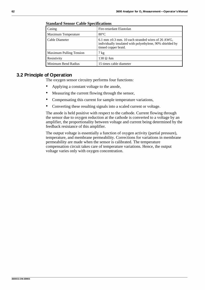
62 3600 Analyzer for O2 Measurement—Operator’s Manual
3600O2.OM.E9903
Standard Sensor Cable SpecificationsCasing Fire-retardant Elastolan
Maximum Temperature 80°C
Cable Diameter 6.1 mm ±0.3 mm. 10 each stranded wires of 26 AWG,individually insulated with polyethylene, 90% shielded bytinned copper braid.
Maximum Pulling Tension 7 kg
Resistivity 138 Ω /km
Minimum Bend Radius 15 times cable diameter
3.2 Principle of OperationThe oxygen sensor circuitry performs four functions:
• Applying a constant voltage to the anode,
• Measuring the current flowing through the sensor,
• Compensating this current for sample temperature variations,
• Converting these resulting signals into a scaled current or voltage.
The anode is held positive with respect to the cathode. Current flowing throughthe sensor due to oxygen reduction at the cathode is converted to a voltage by anamplifier, the proportionality between voltage and current being determined by thefeedback resistance of this amplifier.
The output voltage is essentially a function of oxygen activity (partial pressure),temperature, and membrane permeability. Corrections for variations in membranepermeability are made when the sensor is calibrated. The temperaturecompensation circuit takes care of temperature variations. Hence, the outputvoltage varies only with oxygen concentration.

3600 Analyzer for O2 Measurement—Operator’s Manual 63
3600O2.OM.E9903
Appendix 1—Table of Oxygen Concentrations (ppm)Temperature, °C, in left-hand column; Barometric Pressure, mBar, on top row.1 bar = 1000 mbar; 1000 mbar = 750.1 Torr = 750.1 mmHg = 29.53 inches Hg = 0.987 atm = 14.5 psi = 100 kPa.
T/P 900 905 910 915 920 925 930 935 940 9450 12.99 13.06 13.13 13.21 13.28 13.35 13.43 13.50 13.57 13.641 12.63 12.70 12.77 12.84 12.91 12.98 13.05 13.12 13.19 13.262 12.28 12.35 12.42 12.49 12.56 12.63 12.70 12.77 12.83 12.903 11.96 12.02 12.09 12.16 12.22 12.29 12.36 12.42 12.49 12.564 11.64 11.71 11.77 11.84 11.90 11.97 12.03 12.10 12.16 12.235 11.34 11.40 11.47 11.53 11.59 11.66 11.72 11.79 11.85 11.916 11.05 11.11 11.18 11.24 11.30 11.36 11.42 11.49 11.55 11.617 10.78 10.84 10.90 10.96 11.02 11.08 11.14 11.20 11.26 11.328 10.51 10.57 10.63 10.69 10.75 10.81 10.87 10.93 10.99 11.059 10.26 10.32 10.38 10.43 10.49 10.55 10.61 10.66 10.72 10.78
10 10.02 10.07 10.13 10.19 10.24 10.30 10.36 10.41 10.47 10.5311 9.79 9.84 9.90 9.95 10.01 10.06 10.12 10.17 10.23 10.2812 9.56 9.62 9.67 9.72 9.78 9.83 9.89 9.94 9.99 10.0513 9.35 9.40 9.45 9.51 9.56 9.61 9.66 9.72 9.77 9.8214 9.14 9.19 9.25 9.30 9.35 9.40 9.45 9.50 9.56 9.6115 8.94 8.99 9.04 9.10 9.15 9.20 9.25 9.30 9.35 9.4016 8.75 8.80 8.85 8.90 8.95 9.00 9.05 9.10 9.15 9.2017 8.57 8.62 8.67 8.72 8.76 8.81 8.86 8.91 8.96 9.0118 8.39 8.44 8.49 8.54 8.58 8.63 8.68 8.73 8.77 8.8219 8.22 8.27 8.31 8.36 8.41 8.46 8.50 8.55 8.60 8.6420 8.06 8.10 8.15 8.19 8.24 8.29 8.33 8.38 8.42 8.4721 7.90 7.94 7.99 8.03 8.08 8.12 8.17 8.21 8.26 8.3022 7.74 7.79 7.83 7.88 7.92 7.97 8.01 8.05 8.10 8.1423 7.60 7.64 7.68 7.73 7.77 7.81 7.86 7.90 7.94 7.9924 7.45 7.49 7.54 7.58 7.62 7.67 7.71 7.75 7.79 7.8425 7.31 7.36 7.40 7.44 7.48 7.52 7.57 7.61 7.65 7.6926 7.18 7.22 7.26 7.30 7.34 7.39 7.43 7.47 7.51 7.5527 7.05 7.09 7.13 7.17 7.21 7.25 7.29 7.33 7.37 7.4228 6.92 6.96 7.00 7.04 7.08 7.12 7.16 7.20 7.24 7.2829 6.80 6.84 6.88 6.92 6.96 7.00 7.04 7.08 7.12 7.1530 6.68 6.72 6.76 6.80 6.84 6.87 6.91 6.95 6.99 7.0331 6.56 6.60 6.64 6.68 6.72 6.76 6.79 6.83 6.87 6.9132 6.45 6.49 6.53 6.56 6.60 6.64 6.68 6.72 6.75 6.7933 6.34 6.38 6.42 6.45 6.49 6.53 6.56 6.60 6.64 6.6834 6.23 6.27 6.31 6.34 6.38 6.42 6.45 6.49 6.53 6.5635 6.13 6.17 6.20 6.24 6.27 6.31 6.35 6.38 6.42 6.4636 6.03 6.06 6.10 6.13 6.17 6.21 6.24 6.28 6.31 6.3537 5.93 5.96 6.00 6.03 6.07 6.10 6.14 6.17 6.21 6.2538 5.83 5.86 5.90 5.93 5.97 6.00 6.04 6.07 6.11 6.1439 5.73 5.77 5.80 5.84 5.87 5.91 5.94 5.98 6.01 6.0440 5.64 5.67 5.71 5.74 5.78 5.81 5.85 5.88 5.91 5.9541 5.55 5.58 5.62 5.65 5.68 5.72 5.75 5.78 5.82 5.8542 5.46 5.49 5.52 5.56 5.59 5.62 5.66 5.69 5.73 5.7643 5.37 5.40 5.44 5.47 5.50 5.53 5.57 5.60 5.63 5.6744 5.28 5.31 5.35 5.38 5.41 5.45 5.48 5.51 5.54 5.5845 5.20 5.23 5.26 5.29 5.33 5.36 5.39 5.42 5.45 5.4946 5.11 5.14 5.17 5.21 5.24 5.27 5.30 5.33 5.37 5.4047 5.03 5.06 5.09 5.12 5.15 5.19 5.22 5.25 5.28 5.3148 4.94 4.98 5.01 5.04 5.07 5.10 5.13 5.16 5.19 5.2349 4.86 4.89 4.92 4.96 4.99 5.02 5.05 5.08 5.11 5.14
(1st of 4)

64 3600 Analyzer for O2 Measurement—Operator’s Manual
3600O2.OM.E9903
Table of Oxygen Concentrations (ppm)—ContinuedTemperature, °C, in left-hand column; Barometric Pressure, mBar, on top row.
T/P 950 955 960 965 970 975 980 985 990 9950 13.72 13.79 13.86 13.93 14.01 14.08 14.15 14.22 14.30 14.371 13.34 13.41 13.48 13.55 13.62 13.69 13.76 13.83 13.90 13.972 12.97 13.04 13.11 13.18 13.25 13.32 13.38 13.45 13.52 13.593 12.62 12.69 12.76 12.83 12.89 12.96 13.03 13.09 13.16 13.234 12.29 12.36 12.42 12.49 12.55 12.62 12.68 12.75 12.82 12.885 11.98 12.04 12.10 12.17 12.23 12.29 12.36 12.42 12.49 12.556 11.67 11.74 11.80 11.86 11.92 11.98 12.05 12.11 12.17 12.237 11.38 11.44 11.50 11.56 11.62 11.69 11.75 11.81 11.87 11.938 11.10 11.16 11.22 11.28 11.34 11.40 11.46 11.52 11.58 11.649 10.84 10.90 10.95 11.01 11.07 11.13 11.18 11.24 11.30 11.36
10 10.58 10.64 10.70 10.75 10.81 10.86 10.92 10.98 11.03 11.0911 10.34 10.39 10.45 10.50 10.56 10.61 10.67 10.72 10.78 10.8312 10.10 10.16 10.21 10.26 10.32 10.37 10.43 10.48 10.53 10.5913 9.88 9.93 9.98 10.03 10.09 10.14 10.19 10.25 10.30 10.3514 9.66 9.71 9.76 9.81 9.87 9.92 9.97 10.02 10.07 10.1215 9.45 9.50 9.55 9.60 9.65 9.70 9.75 9.80 9.86 9.9116 9.25 9.30 9.35 9.40 9.45 9.50 9.55 9.60 9.65 9.7017 9.06 9.10 9.15 9.20 9.25 9.30 9.35 9.40 9.44 9.4918 8.87 8.92 8.96 9.01 9.06 9.11 9.16 9.20 9.25 9.3019 8.69 8.74 8.78 8.83 8.88 8.92 8.97 9.02 9.06 9.1120 8.52 8.56 8.61 8.65 8.70 8.75 8.79 8.84 8.88 8.9321 8.35 8.39 8.44 8.48 8.53 8.57 8.62 8.66 8.71 8.7622 8.19 8.23 8.28 8.32 8.36 8.41 8.45 8.50 8.54 8.5923 8.03 8.07 8.12 8.16 8.21 8.25 8.29 8.34 8.38 8.4224 7.88 7.92 7.97 8.01 8.05 8.09 8.14 8.18 8.22 8.2725 7.73 7.78 7.82 7.86 7.90 7.94 7.99 8.03 8.07 8.1126 7.59 7.63 7.68 7.72 7.76 7.80 7.84 7.88 7.92 7.9727 7.46 7.50 7.54 7.58 7.62 7.66 7.70 7.74 7.78 7.8228 7.32 7.36 7.40 7.44 7.48 7.52 7.56 7.60 7.64 7.6829 7.19 7.23 7.27 7.31 7.35 7.39 7.43 7.47 7.51 7.5530 7.07 7.11 7.15 7.19 7.22 7.26 7.30 7.34 7.38 7.4231 6.95 6.99 7.02 7.06 7.10 7.14 7.18 7.22 7.25 7.2932 6.83 6.87 6.90 6.94 6.98 7.02 7.06 7.09 7.13 7.1733 6.71 6.75 6.79 6.83 6.86 6.90 6.94 6.98 7.01 7.0534 6.60 6.64 6.68 6.71 6.75 6.79 6.82 6.86 6.90 6.9335 6.49 6.53 6.56 6.60 6.64 6.67 6.71 6.75 6.78 6.8236 6.39 6.42 6.46 6.49 6.53 6.56 6.60 6.64 6.67 6.7137 6.28 6.32 6.35 6.39 6.42 6.46 6.49 6.53 6.56 6.6038 6.18 6.21 6.25 6.28 6.32 6.35 6.39 6.42 6.46 6.4939 6.08 6.11 6.15 6.18 6.22 6.25 6.29 6.32 6.36 6.3940 5.98 6.02 6.05 6.08 6.12 6.15 6.19 6.22 6.25 6.2941 5.89 5.92 5.95 5.99 6.02 6.05 6.09 6.12 6.16 6.1942 5.79 5.83 5.86 5.89 5.93 5.96 5.99 6.03 6.06 6.0943 5.70 5.73 5.77 5.80 5.83 5.86 5.90 5.93 5.96 6.0044 5.61 5.64 5.67 5.71 5.74 5.77 5.80 5.84 5.87 5.9045 5.52 5.55 5.58 5.62 5.65 5.68 5.71 5.75 5.78 5.8146 5.43 5.46 5.49 5.53 5.56 5.59 5.62 5.65 5.69 5.7247 5.34 5.38 5.41 5.44 5.47 5.50 5.53 5.57 5.60 5.6348 5.26 5.29 5.32 5.35 5.38 5.41 5.45 5.48 5.51 5.5449 5.17 5.20 5.23 5.27 5.30 5.33 5.36 5.39 5.42 5.45
(2nd of 4)

3600 Analyzer for O2 Measurement—Operator’s Manual 65
3600O2.OM.E9903

66 3600 Analyzer for O2 Measurement—Operator’s Manual
3600O2.OM.E9903
Table of Oxygen Concentrations (ppm)—ContinuedTemperature, °C, in left-hand column; Barometric Pressure, mBar, on top row.
T/P 1000 1005 1010 1015 1020 1025 1030 1035 1040 10450 14.44 14.52 14.59 14.66 14.73 14.81 14.88 14.95 15.02 15.101 14.04 14.11 14.18 14.25 14.32 14.40 14.47 14.54 14.61 14.682 13.66 13.73 13.80 13.87 13.93 14.00 14.07 14.14 14.21 14.283 13.29 13.36 13.43 13.50 13.56 13.63 13.70 13.76 13.83 13.904 12.95 13.01 13.08 13.14 13.21 13.27 13.34 13.40 13.47 13.535 12.61 12.68 12.74 12.80 12.87 12.93 12.99 13.06 13.12 13.196 12.29 12.36 12.42 12.48 12.54 12.60 12.67 12.73 12.79 12.857 11.99 12.05 12.11 12.17 12.23 12.29 12.35 12.41 12.47 12.538 11.70 11.75 11.81 11.87 11.93 11.99 12.05 12.11 12.17 12.239 11.42 11.47 11.53 11.59 11.65 11.70 11.76 11.82 11.88 11.94
10 11.15 11.20 11.26 11.32 11.37 11.43 11.49 11.54 11.60 11.6511 10.89 10.94 11.00 11.05 11.11 11.17 11.22 11.28 11.33 11.3912 10.64 10.70 10.75 10.80 10.86 10.91 10.97 11.02 11.07 11.1313 10.40 10.46 10.51 10.56 10.62 10.67 10.72 10.77 10.83 10.8814 10.18 10.23 10.28 10.33 10.38 10.43 10.49 10.54 10.59 10.6415 9.96 10.01 10.06 10.11 10.16 10.21 10.26 10.31 10.36 10.4116 9.75 9.80 9.84 9.89 9.94 9.99 10.04 10.09 10.14 10.1917 9.54 9.59 9.64 9.69 9.74 9.79 9.83 9.88 9.93 9.9818 9.35 9.39 9.44 9.49 9.54 9.59 9.63 9.68 9.73 9.7819 9.16 9.20 9.25 9.30 9.35 9.39 9.44 9.49 9.53 9.5820 8.98 9.02 9.07 9.11 9.16 9.21 9.25 9.30 9.34 9.3921 8.80 8.85 8.89 8.94 8.98 9.03 9.07 9.12 9.16 9.2122 8.63 8.68 8.72 8.76 8.81 8.85 8.90 8.94 8.99 9.0323 8.47 8.51 8.55 8.60 8.64 8.68 8.73 8.77 8.82 8.8624 8.31 8.35 8.39 8.44 8.48 8.52 8.57 8.61 8.65 8.6925 8.16 8.20 8.24 8.28 8.32 8.37 8.41 8.45 8.49 8.5326 8.01 8.05 8.09 8.13 8.17 8.21 8.26 8.30 8.34 8.3827 7.86 7.90 7.95 7.99 8.03 8.07 8.11 8.15 8.19 8.2328 7.72 7.76 7.80 7.84 7.89 7.93 7.97 8.01 8.05 8.0929 7.59 7.63 7.67 7.71 7.75 7.79 7.83 7.87 7.91 7.9530 7.46 7.50 7.54 7.58 7.61 7.65 7.69 7.73 7.77 7.8131 7.33 7.37 7.41 7.45 7.48 7.52 7.56 7.60 7.64 7.6832 7.21 7.25 7.28 7.32 7.36 7.40 7.43 7.47 7.51 7.5533 7.09 7.12 7.16 7.20 7.24 7.27 7.31 7.35 7.39 7.4234 6.97 7.01 7.04 7.08 7.12 7.15 7.19 7.23 7.26 7.3035 6.86 6.89 6.93 6.96 7.00 7.04 7.07 7.11 7.15 7.1836 6.74 6.78 6.82 6.85 6.89 6.92 6.96 6.99 7.03 7.0737 6.64 6.67 6.71 6.74 6.78 6.81 6.85 6.88 6.92 6.9538 6.53 6.56 6.60 6.63 6.67 6.70 6.74 6.77 6.81 6.8439 6.42 6.46 6.49 6.53 6.56 6.60 6.63 6.67 6.70 6.7440 6.32 6.36 6.39 6.43 6.46 6.49 6.53 6.56 6.60 6.6341 6.22 6.26 6.29 6.32 6.36 6.39 6.43 6.46 6.49 6.5342 6.13 6.16 6.19 6.23 6.26 6.29 6.33 6.36 6.39 6.4343 6.03 6.06 6.10 6.13 6.16 6.19 6.23 6.26 6.29 6.3344 5.94 5.97 6.00 6.03 6.07 6.10 6.13 6.16 6.20 6.2345 5.84 5.87 5.91 5.94 5.97 6.00 6.04 6.07 6.10 6.1346 5.75 5.78 5.81 5.85 5.88 5.91 5.94 5.97 6.01 6.0447 5.66 5.69 5.72 5.76 5.79 5.82 5.85 5.88 5.91 5.9548 5.57 5.60 5.63 5.67 5.70 5.73 5.76 5.79 5.82 5.8549 5.48 5.51 5.55 5.58 5.61 5.64 5.67 5.70 5.73 5.76
(3rd of 4)

3600 Analyzer for O2 Measurement—Operator’s Manual 67
3600O2.OM.E9903

68 3600 Analyzer for O2 Measurement—Operator’s Manual
3600O2.OM.E9903
Table of Oxygen Concentrations (ppm)—ContinuedTemperature, °C, in left-hand column; Barometric Pressure, mBar, on top row.
T/P 1050 1055 1060 1065 1070 1075 1080 1085 1090 10950 15.17 15.24 15.31 15.39 15.46 15.53 15.60 15.68 15.75 15.821 14.75 14.82 14.89 14.96 15.03 15.10 15.17 15.24 15.31 15.382 14.35 14.42 14.49 14.55 14.62 14.69 14.76 14.83 14.90 14.973 13.96 14.03 14.10 14.17 14.23 14.30 14.37 14.43 14.50 14.574 13.60 13.66 13.73 13.79 13.86 13.92 13.99 14.06 14.12 14.195 13.25 13.31 13.38 13.44 13.50 13.57 13.63 13.69 13.76 13.826 12.91 12.98 13.04 13.10 13.16 13.22 13.29 13.35 13.41 13.477 12.59 12.65 12.71 12.78 12.84 12.90 12.96 13.02 13.08 13.148 12.29 12.35 12.41 12.46 12.52 12.58 12.64 12.70 12.76 12.829 11.99 12.05 12.11 12.17 12.22 12.28 12.34 12.40 12.45 12.51
10 11.71 11.77 11.82 11.88 11.94 11.99 12.05 12.11 12.16 12.2211 11.44 11.50 11.55 11.61 11.66 11.72 11.77 11.83 11.88 11.9412 11.18 11.24 11.29 11.34 11.40 11.45 11.51 11.56 11.61 11.6713 10.93 10.99 11.04 11.09 11.14 11.20 11.25 11.30 11.36 11.4114 10.69 10.74 10.80 10.85 10.90 10.95 11.00 11.06 11.11 11.1615 10.46 10.51 10.56 10.62 10.67 10.72 10.77 10.82 10.87 10.9216 10.24 10.29 10.34 10.39 10.44 10.49 10.54 10.59 10.64 10.6917 10.03 10.08 10.13 10.17 10.22 10.27 10.32 10.37 10.42 10.4718 9.82 9.87 9.92 9.97 10.01 10.06 10.11 10.16 10.21 10.2519 9.63 9.67 9.72 9.77 9.81 9.86 9.91 9.95 10.00 10.0520 9.44 9.48 9.53 9.57 9.62 9.67 9.71 9.76 9.80 9.8521 9.25 9.30 9.34 9.39 9.43 9.48 9.52 9.57 9.61 9.6622 9.07 9.12 9.16 9.21 9.25 9.30 9.34 9.38 9.43 9.4723 8.90 8.95 8.99 9.03 9.08 9.12 9.16 9.21 9.25 9.2924 8.74 8.78 8.82 8.87 8.91 8.95 8.99 9.04 9.08 9.1225 8.58 8.62 8.66 8.70 8.75 8.79 8.83 8.87 8.91 8.9626 8.42 8.46 8.50 8.55 8.59 8.63 8.67 8.71 8.75 8.7927 8.27 8.31 8.35 8.39 8.43 8.48 8.52 8.56 8.60 8.6428 8.13 8.17 8.21 8.25 8.29 8.33 8.37 8.41 8.45 8.4929 7.98 8.02 8.06 8.10 8.14 8.18 8.22 8.26 8.30 8.3430 7.85 7.89 7.93 7.96 8.00 8.04 8.08 8.12 8.16 8.2031 7.72 7.75 7.79 7.83 7.87 7.91 7.95 7.98 8.02 8.0632 7.59 7.62 7.66 7.70 7.74 7.78 7.81 7.85 7.89 7.9333 7.46 7.50 7.53 7.57 7.61 7.65 7.68 7.72 7.76 7.8034 7.34 7.37 7.41 7.45 7.49 7.52 7.56 7.60 7.63 7.6735 7.22 7.26 7.29 7.33 7.36 7.40 7.44 7.47 7.51 7.5536 7.10 7.14 7.17 7.21 7.25 7.28 7.32 7.35 7.39 7.4337 6.99 7.02 7.06 7.10 7.13 7.17 7.20 7.24 7.27 7.3138 6.88 6.91 6.95 6.98 7.02 7.05 7.09 7.12 7.16 7.1939 6.77 6.80 6.84 6.87 6.91 6.94 6.98 7.01 7.05 7.0840 6.66 6.70 6.73 6.77 6.80 6.84 6.87 6.90 6.94 6.9741 6.56 6.59 6.63 6.66 6.70 6.73 6.76 6.80 6.83 6.8642 6.46 6.49 6.53 6.56 6.59 6.63 6.66 6.69 6.73 6.7643 6.36 6.39 6.43 6.46 6.49 6.52 6.56 6.59 6.62 6.6644 6.26 6.29 6.33 6.36 6.39 6.42 6.46 6.49 6.52 6.5645 6.17 6.20 6.23 6.26 6.29 6.33 6.36 6.39 6.42 6.4646 6.07 6.10 6.13 6.17 6.20 6.23 6.26 6.29 6.33 6.3647 5.98 6.01 6.04 6.07 6.10 6.14 6.17 6.20 6.23 6.2648 5.89 5.92 5.95 5.98 6.01 6.04 6.07 6.10 6.14 6.1749 5.79 5.83 5.86 5.89 5.92 5.95 5.98 6.01 6.04 6.07
(4th of 4)

3600 Analyzer for O2 Measurement—Operator’s Manual 69
3600O2.OM.E9903
IndexInstrument LCD message entries in boldIllustration entries in italics
A
air oxygen sensor calibration........................................12alarm outputs.................................................................21
alarm configurations ................................................21alarm relay responses ...............................................21description ................................................................21options menu ............................................................20wiring identification.................................................51
ammonia cleaning..........................................................30analog outputs ...............................................................22
O2 concentration output signal ................................22options menu ............................................................21output conversion.....................................................54pressure output signal ..............................................23range output signal...................................................23temperature output signal ........................................23wiring identification.................................................51
analyzer components .......................................................5arrow keys........................................................................8ATTENTION HIGH LIMIT.......................................11ATTENTION LOW LIMIT........................................11autoranging display mode ...................................... 10, 18
B
battery replacement........................................................54Binder connector .................................................... 44, 49
C
cable gland wiring instructions.....................................52cable glands....................................................................52cable requirements.........................................................52calibration......................................................................12
external pressure sensor ...........................................14hydrogen compensation for oxygen sensor .............16instrument barometric pressure ...............................12oxygen sensor
direct ....................................................................14in air .....................................................................12
calibration menu............................................................12calibration menu flow chart ..........................................9CALIBRATION OUT OF BOUNDS ................ 13, 14check instrument connections.........................................6check instrument mounting.............................................6check sensor placement ...................................................7check the oxygen sensor..................................................6CHECK THE SENSOR .............................................11check the voltage and line power....................................6
chemical cleaning ......................................................... 29ammonia cleaning.................................................... 30nitric acid cleaning................................................... 30
CO2/H2S insensitivity................................................... 26components......................................................................5connectors...............................................................50–51
alarm output............................................................. 51Binder connector ...............................................44, 49cable gland wiring instructions............................... 52external pressure sensor .......................................... 50LEMO connector assembly instructions ................ 52oxygen sensor........................................................... 50recorder (analog) output ......................................... 51RS-232 (serial) output ............................................ 50
D
data acquisition software ..........................see moca3600direct oxygen sensor calibration .................................. 14display ranges................................................................ 19display units option ...................................................... 18
dissolved ............................................................18, 19fraction...............................................................18, 19partial pressure...................................................18, 19
dissolved display units.................................................. 18
E
electrochemical cleaning.............................................. 29electromagnetic compatibility (EMC) standards ...........2ENTER key......................................................................8ESC key............................................................................8external pressure sensor
calibration................................................................ 14input wiring identification ...................................... 50installation ............................................................... 59
F
flow chamber installation............................................. 56flow chamber mounting .............................................. 57fraction display units .................................................... 18fuse replacement ........................................................... 54
G
gas to measure option................................................... 26general alarm................................................................. 20
H
H2 compensation option............................................... 25high limit....................................................................... 20

70 3600 Analyzer for O2 Measurement—Operator’s Manual
3600O2.OM.E9903
high/high limit .............................................................. 20hydrogen compensation................................................ 25hydrogen compensation calibration............................. 16
I
indicating instrument.................................see instrumentinstallation .................................................................... 42
AC power connections ................................44, 47, 48cable gland wiring instructions............................... 52cable requirements................................................... 52connectors..........................................................50–51DC power connections................................44, 48, 49external pressure sensor .......................................... 59instrument ................................................................ 42LEMO connector assembly instructions ................ 52oxygen sensor........................... see sensor installationpanel mount ..........see panel mount instr. installationportable ........................see portable instr. installationrack mount ..............see rack mount instr. installationsensor ....................................................................... 55wall mount ..............see wall mount instr. installationwiring information ............................................52–53
instrument ........................................................................5AC power connections ................................44, 47, 48analog output conversion........................................ 54barometric pressure calibration .............................. 12battery replacement (portable instrument).............. 54cable glands ............................................................ 53check connections.......................................................6check mounting...........................................................6component replacements and modifications .......... 53configurations.......................................................... 60connectors..........................................................50–51DC power connections................................44, 48, 49electrical signal connections .......................44, 48, 49front panel controls ...................................................5front panel keyswitch.................................................8function keys...............................................................8fuse replacement ...................................................... 54installation ............................................................... 42jumpers, analog current/voltage switch.................. 54liquid crystal display (LCD).......................................5mounting......................................................42, 46, 48operation.....................................................................8panel mounting ....................................................... 42power input..................................................44, 47, 48program flow charts ...................................................9rack mounting ......................................................... 43rear panel, panel/rack mount instrument............. 45rear panel, portable instrument ............................ 49retrofit panel mounting .......................................... 43service ...................................................................... 53specifications ........................................................... 60terminal strip.....................................................45, 46
wall mounting ......................................................... 46wiring label .......................................................45, 46
J
jumpers, analog current/voltage switch....................... 54
L
LEMO connector assembly ......................................... 52LEMO connector assembly instructions...................... 52LEMO-10—oxygen sensor.......................................... 50LEMO-4—external pressure sensor........................... 50LEMO-6—alarm output ............................................. 51LEMO-6—RS-232 (serial) output.............................. 50LEMO-8—recorder (analog) output ......................... 51liquid crystal display (LCD)........................................... 5LOW BATTERY ....................................................6, 54low limit........................................................................ 20
M
main menu....................................................................... 8maintenance.......................................... see sensor servicemask......................................................... see sensor maskmeasure menu flow chart .............................................. 9measurement ................................................................. 10
after use and storage ..........................................11, 32analog outputs.......................................................... 22autoranging mode .................................................... 10display ranges........................................................... 19display units ............................................................. 18outputs...................................................................... 11oxygen measurement display................................... 10range indication........................................................ 10stabilization.............................................................. 10temperature units ..................................................... 19warning messages .................................................... 11
membrane............................................................6, 28, 31characteristics........................................................... 61selection option........................................................ 27
membrane holding ring.......................................6, 28, 31membrane support .................................7, 28, 29, 30, 31moca3600 ..................................................................... 37
Acquiring data.......................................................... 39Configuration menu
Communications................................................. 38Data acquisition.................................................. 39Gas selection....................................................... 39
copying data ............................................................. 40Export menu
To clipboard........................................................ 40File menu
Print ..................................................................... 40Save as................................................................. 40
Menu overview ........................................................ 38printing data ............................................................. 40
3600 Analyzer for O2 Measurement—Operator’s Manual 71
3600O2.OM.E9903
program setup...........................................................37saving data ................................................................40Terminal menu
End .......................................................................39Go.........................................................................39
Windows 3.1 setup...................................................37Windows 95 setup....................................................37
modify options...............................................................17alarm limits...............................................................20analog outputs ..........................................................21display units..............................................................18gas to measure ..........................................................26H2 Compensation .....................................................25membrane..................................................................27rolling average..........................................................26salinity and chlorinity...............................................24self diagnostics .........................................................25serial output..............................................................24thermal cutoff ...........................................................20
modify options menu ....................................................17modify options menu flow chart..................................17multiparameter flow chamber installation...................58multiparameter flow chamber mounting....................58
N
nitric acid cleaning ........................................................30
O
O2 concentration output signal .....................................22options ................................................see modify optionsOVERRANGE RANGE 0..........................................10OVERRANGE RANGE n..........................................11oxygen sensor ..................................................................5
assembly view.............................................................6calibration
direct ....................................................................14in air .....................................................................12
check placement..........................................................7components, exploded view ......................................5dimensions................................................................55hydrogen compensation............................................16installation................................see sensor installationprinciple of operation...............................................62sensor service...................................see sensor servicewiring identification.................................................50
oxygen sensor and protection cap diagram...............35
P
panel mount instrument installation.............................42AC power connections.............................................44DC power connections.............................................44electrical signal connections....................................44instrument rear panel..............................................45mounting...................................................................42
mounting illustration ............................................. 42power input.............................................................. 44retrofit panel mount illustration ........................... 43
partial pressure display units........................................ 18polish sensor face ......................................................... 30portable instrument installation................................... 48
AC power connections ............................................ 48DC power connections............................................ 49electrical signal connections ................................... 49instrument rear panel ............................................. 49mounting.................................................................. 48power input.............................................................. 48
power inputAC power connections ................................44, 47, 48DC power connections................................44, 48, 49
prepare sensor for cleaning .......................................... 28pressure output signal .................................................. 23principle of operation................................................... 62ProAcc insertion/extraction valve installation............ 56ProAcc mounting ......................................................... 56protection cap .........................................................28, 32protection cap components......................................... 35protection cap kits ........................................................ 36put sensor back into service ......................................... 32
Q
quality standard................................................................2
R
rack mount instrument installation.............................. 42AC power connections ............................................ 44DC power connections............................................ 44electrical signal connections ................................... 44instrument rear panel ............................................. 45mounting.................................................................. 42mounting illustration ............................................. 43power input.............................................................. 44
range output signal ....................................................... 23rear panel, portable instrument ................................. 49rear panel, rack/panel mount instrument.................. 45recharge kit.......................................................................5recharge kits
contents .................................................................... 34recorder output ...................................see analog outputsremove sensor from sample ......................................... 28replace membrane......................................................... 31rolling average option .................................................. 26RS-232 output ........................................see serial output
S
safety................................................................................2safety standard..................................................................2salinity and chlorinity option ....................................... 24self diagnostics option.................................................. 25

72 3600 Analyzer for O2 Measurement—Operator’s Manual
3600O2.OM.E9903
sensorconfigurations.......................................................... 61expected.................................................................... 61specifications ........................................................... 61
Sensor Cleaning and Regeneration Center .................. 29sensor current display................................................... 25sensor current, expected values.................................... 61sensor installation......................................................... 55
flow chamber ........................................................... 56flow chamber mounting ......................................... 57multiparameter flow chamber................................. 58multiparameter flow chamber mounting .............. 58ProAcc insertion/extraction valve .......................... 56ProAcc mounting .................................................... 56sensor socket............................................................ 55sensor socket mounting .......................................... 55
sensor mask.........................................................6, 29, 31sensor service................................................................ 28
chemical cleaning .................................................... 29ammonia cleaning............................................... 30nitric acid cleaning.............................................. 30
electrochemical cleaning......................................... 29polish sensor face .................................................... 30prepare sensor for cleaning ..................................... 28put sensor back into service .................................... 32remove sensor from sample .................................... 28replace membrane.................................................... 31when to perform a sensor service ........................... 28
sensor socket installation............................................. 55sensor socket mounting ............................................... 55serial (RS-232) output wiring identification.............. 50serial output option...................................................... 24shutting down the system ............................................. 32spare parts ..................................................................... 34system specifications.................................................... 60
expected sensor current ........................................... 61instrument configurations....................................... 60instrument specifications ........................................ 60membrane characteristics ........................................ 61
sensor cable specifications ...................................... 62sensor configurations .............................................. 61sensors...................................................................... 61
T
technical information.................................................... 60temperature output signal............................................. 23temperature units .......................................................... 19terminal strip wiring connections ................................ 45thermal cutoff option.................................................... 20troubleshooting............................................................. 33
U
user-supplied cabling requirements ............................. 52
V
voltage and line power check ......................................... 6
W
wall mount instrument installation.............................. 46AC power connections ............................................ 47DC power connections ............................................ 48electrical signal connections ................................... 48instrument bottom view .......................................... 47mounting .................................................................. 46mounting illustration.............................................. 46power input .............................................................. 47terminal blocks location......................................... 48
warning messages ......................................................... 11WARNING THERMAL CUTOFF ....................11, 20warranty......................................................................... 41when to perform a sensor service................................. 28wiring identification
alarm output............................................................. 51external pressure sensor input................................. 50oxygen sensor........................................................... 50recorder (analog) output.......................................... 51RS-232 (serial) output ............................................ 50
wiring information..................................................52–53