Embed Size (px)
Citation preview

36”, 48", 52"Hydrostatic Walk-Behind
Commercial Rotary MowersStandard
Professional Turf Equipment
OPERATOR’S AND SERVICE MANUAL

SECTION 1: TABLE OF CONTENTS
FOREWORD.................................................................................................................3
SAFETY PRECAUTIONS .............................................................................................4
SAFETY DECALS FOUND ON YOUR UNIT ................................................................6
SPECIFICATIONS.........................................................................................................8
OPERATING INSTRUCTIONS .....................................................................................9
CONTROLS ..................................................................................................................9
INITIAL ADJUSTMENTS...............................................................................................11
BREAK-IN AND OPERATION.......................................................................................12
CUTTING HEIGHT ADJUSTMENT TABLE ..................................................................13
MAINTENANCE ............................................................................................................14
TO CHANGE A BLADE:................................................................................................16
TO CHANGE THE BLADE DRIVE BELTS:...................................................................16
TO CHANGE THE PUMP DRIVE BELT:. ......................................................................21
TO CHANGE A SPINDLE ASSEMBLY .........................................................................21
Remove the spindle assembly.......................................................................................21
REPLACEMENT PARTS...............................................................................................22
SLOPE GAUGE ............................................................................................................23
WARRANTY..................................................................................................................24
2
SECTION 2: FOREWORDThe Cub Cadet Commercial Hydro Walk-Behind Commercial Rotary Mower has been developed for use by professional landscapers, commercial lawn service companies, professional turf managers and golf course superintendents. The machine incorporates many safety features that should be studied by all operators and maintenance personnel before use. The list of safety precautions should receive particular attention. This manual presents the operating and maintenance instructions necessary to keep your Cub Cadet Commercial mower at peak efficiency. If properly operated and maintained, your Cub Cadet Commercial mower will give dependable and trouble-free service. Although hazard control and accident prevention are partially dependent upon the design and configuration of the equipment, these factors are also dependent upon the awareness, concern, prudence, and proper training of the personnel involved in the operation, transport, maintenance and storage of the equipment.
The Cub Cadet Commercial Hydro Walk-Behind Commercial Rotary Mower should only be operated and maintained by thoroughly trained individuals. The machine could cause serious injury to anyone who misuses it or does not under-stand its operation. All operators and maintenance personnel are urged to read this entire manual for their personal safety.
3
SECTION 3: SAFETY PRECAUTIONSA. GENERAL: 1. Read this Operator’s Manual before starting the mower. Study the controls and learn the proper sequence of operation.
2. Do not allow anyone to operate or maintain this machine who has not read the manual. Never permit children to operate this machine.
3. Always have your feet and hands clear of the cutter deck when starting the engine.
4. Do not remove any shields, guards, decals or safety devices. If a shield, guard, decal or safety device is damaged or does not function, repair or replace it before operating the mower.
5. Always wear safety glasses, long pants and safety shoes when operating or maintaining this mower. Do not wear loose-fitting clothing.
6. Never run the engine indoors without adequate ventilation. Exhaust fumes are deadly. 7. To avoid serious burns, do not touch the engine or muffler while the engine is running or until it has cooled after it has
been shut off.
8. When looking for oil leaks, never run your hand over hydraulic hoses, lines or fittings. (High-pressure oil can easily penetrate the skin.) Never tighten or adjust hydraulic hoses or fittings while the system is under pressure.
B. RELATED TO FUEL: 1. Gasoline is highly flammable. Respect it. 2. Do not smoke or permit others to smoke while handling gasoline.
3. Always use approved containers for gasoline.
4. Always shut off the engine and permit it to cool before removing the cap of the fuel tank.
5. If the fuel container spout will not fit inside the fuel tank opening, use a funnel.
6. When filling the fuel tank, stop when the gasoline reaches one inch from the top. This space must be left for expansion. Do not overfill. Always fill the fuel tank outdoors away from sparks and flames.
7. Wipe up any spilled gasoline.
C. WHEN MOWING: 1. Keep adults, children and pets away from the area to be mowed.
2. Never use this mower without the grasscatcher or discharge chute installed and set in the down position.
3. Mow only in daylight.
4. Always check the area to be mowed and remove debris and other objects prior to mowing.
5. Watch for holes, sprinkler heads and other hidden hazards.
6. Reduce speed when making sharp turns.
7. Always have proper footing on slopes and hillsides and never operate when conditions are slippery. Be very careful on wet grass.
8. Always keep both hands on the handles. Always walk, never run. 9. Never engage the blade clutch when the engine is running unless you are on grass that you intend to mow.
10. Be careful when crossing gravel paths or roadways. Always disengage the blade clutch and wait until the blades stop rotating.
11. Never leave the mower unattended without disengaging the blade clutch, placing the ground speed control levers in neutral, placing the neutral latch levers in the neutral lock position, shutting off the engine, taking the key from the ignition switch and closing the fuel shutoff valve.
12. Always park the mower and start the engine on a level surface with the ground speed control levers in neutral, the blade clutch disengaged and the neutral latch levers in the neutral lock position.
13. Shut off the engine and wait for the blades to stop rotating before removing the grass catcher.
4

14. If you hit a solid object while mowing, disengage the blade clutch, place the ground speed control levers in neutral, place the neutral latch levers in the neutral lock position and stop the engine. Disconnect the spark plug wire and inspect for damage. Repair any damage and make sure the blades are in good condition and the blade bolts are tight before restarting the engine.
15. Do not mow excessively steep slopes. Mow across the slope, not up and down the slope.
16. Never raise the mower deck while the blades are rotating.
17. Never walk or stand on the discharge side of a mower with the engine running. Disengage the blade clutch if another person approaches while you are operating a mower.
18. Always disconnect the spark plug wire to prevent the engine from accidentally starting before performing any maintenance on this mower.
19. Keep the mower and especially the engine/pump area clean and free of grease, grass and leaves to reduce the chance of fire and to permit proper cooling.
20. The operator presence control levers located at each handle are designed for your safety. Do not try to defeat their operation. If the blade clutch is engaged or either of the ground speed control levers are out of the neutral position, releasing both handles will shut off the mower’s engine.
D. HYDRAULIC DEVICES AND SYSTEMS:Hydraulic fluid escaping under pressure may have sufficient force to penetrate skin and to cause serious imjury. If foreign fluid is injected into the skin, it mst be surgically removed within a few hours by a doctor familiar with this form of injury, or gangrene may result.
Warning: Keep body and hands away from pinholes or nozzles that could eject hydraulic fluid under high pressure. Use paper or cardboard, not hands, to search for leaks!
Safely relieve all pressure in the system before performing any work on the system, and make sure that:• the ignition switch is OFF• the key is removed• the engine sparkplug wire(s) removed• all connections to the negative terminal of the battery are removed• the park brake is set• all by-pass valves, if so equipped, are open• hydraulic controls are actuated to release pressure on pumps, cylinders, etc. If “float” positions are
available, they should be used.
After the above operations are completed, it should be safe to begin disconnecting the lines or components. It is still a good idea to cover the connection with a cloth shield and then gently loosen connections.
Warning: Make sure all hydraulic fluid connections are tight and all hydraulic hoses and lines are in good condition before applying pressure to the system.
5

SECTION 4: SAFETY DECALS FOUND ON YOUR UNITKeep safety decals clean. Replace any safety decal that is damaged, destroyed, missing, painted over or can no longer be read. Replacement safety decals are available through your dealer.
Part Number: 01002166
Part Number: 777S30503
Part Number: 01006669
6

Part Number: 01006132
Part Number: 01001038
Part Number: 01001036
Part Number: 01001035 Part Number: 02002041 Part Number: 01002171
Part Number: 00030635
SAFETY DECALS FOUND ON YOUR UNIT
7
SECTION 5: SPECIFICATIONS
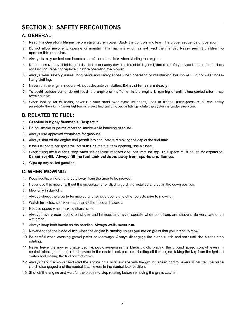
POWER UNIT:MODEL 1536H 1748F 1952F
Engine MFG --------------------- Kawasaki ----------------------
Horsepower 15HP 17HP 19HP
Type ------------------- 4 Cycle Twin --------------------
Starter Recoil ---------------- Electric -----------------
Air Cleaner----- Dual Element Dry -----
Heavy Duty Canister
Lubrication --------------- Pressure with Filter ---------------
Fuel Tank ---------------------- 5 gallon -----------------------
Traction Drive Two variable displacement pumps and two wheel motors
Hyd. Tank ---------------------- 2 gallon -----------------------
Filtration --------------------- 30-micron ---------------------
Ground Speed ---------------------- 0-6 mph ----------------------
Drive Wheels ---------------------- 16 x 6.50-8---------------------
Control Right and left traction/steering levers; right and left ground speed control levers, over-center blade clutch; engine throttle; cutter blade, ground speed control and
operator presence safety group; key-type ignition switch; hour meter.
Frame Steel plate. All welded construction.
Handles 1-1/4" diameter, tubular steel, adjustable.
Mower Type Fixed Fab ---------------------- Float ----------------------
Cutting Width 36 48" 52"
Overall Width 47 58" 62"
Number of Blades 2 ------------------------ 3 ------------------------
Cut Height 2”-4” ----------------- 1-1/2"-4-1/2" -----------------
Deck Material 7 and 10 gauge steel -------------- 11 gauge steel ---------------
Caster Wheels -------------------- 9 x 3.50-4 ----------------------
4-ply tires with inner tubes. Wheels have open-cage roller bearings.
8
SECTION 6:
ParkingBrake Lever
EngineThrottle/Choke
NeutralLatch Lever
Ground SpeedControl Levers
Left Traction Steering Lever
LeverOperator Presence
Electric BladeClutchIgnition
Switch
Choke(Some Models)
StandardBlade Clutch
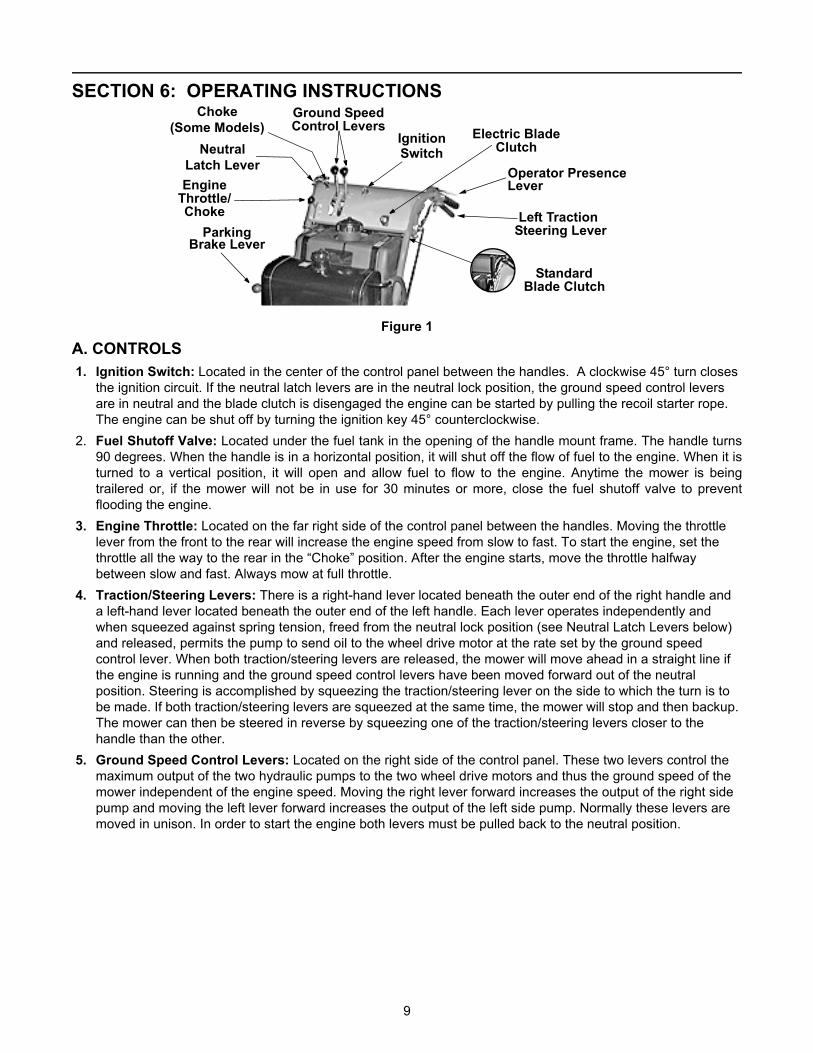
OPERATING INSTRUCTIONS
Figure 1
A. CONTROLS 1. Ignition Switch: Located in the center of the control panel between the handles. A clockwise 45° turn closes
the ignition circuit. If the neutral latch levers are in the neutral lock position, the ground speed control levers are in neutral and the blade clutch is disengaged the engine can be started by pulling the recoil starter rope. The engine can be shut off by turning the ignition key 45° counterclockwise.
2. Fuel Shutoff Valve: Located under the fuel tank in the opening of the handle mount frame. The handle turns 90 degrees. When the handle is in a horizontal position, it will shut off the flow of fuel to the engine. When it is turned to a vertical position, it will open and allow fuel to flow to the engine. Anytime the mower is being trailered or, if the mower will not be in use for 30 minutes or more, close the fuel shutoff valve to prevent flooding the engine.
3. Engine Throttle: Located on the far right side of the control panel between the handles. Moving the throttle lever from the front to the rear will increase the engine speed from slow to fast. To start the engine, set the throttle all the way to the rear in the “Choke” position. After the engine starts, move the throttle halfway between slow and fast. Always mow at full throttle.
4. Traction/Steering Levers: There is a right-hand lever located beneath the outer end of the right handle and a left-hand lever located beneath the outer end of the left handle. Each lever operates independently and when squeezed against spring tension, freed from the neutral lock position (see Neutral Latch Levers below) and released, permits the pump to send oil to the wheel drive motor at the rate set by the ground speed control lever. When both traction/steering levers are released, the mower will move ahead in a straight line if the engine is running and the ground speed control levers have been moved forward out of the neutral position. Steering is accomplished by squeezing the traction/steering lever on the side to which the turn is to be made. If both traction/steering levers are squeezed at the same time, the mower will stop and then backup. The mower can then be steered in reverse by squeezing one of the traction/steering levers closer to the handle than the other.
5. Ground Speed Control Levers: Located on the right side of the control panel. These two levers control the maximum output of the two hydraulic pumps to the two wheel drive motors and thus the ground speed of the mower independent of the engine speed. Moving the right lever forward increases the output of the right side pump and moving the left lever forward increases the output of the left side pump. Normally these levers are moved in unison. In order to start the engine both levers must be pulled back to the neutral position.
9

6. Neutral Latch Levers: Pivoted inside each handle there is a neutral latch lever which works with each of the traction/steering levers. When either of the traction/steering levers is squeezed and its neutral latch lever pushed forward and engaged in the neutral lock position, the traction/steering lever is held in a position where its pump should not be sending any oil to the wheel drive motor. (If this is not the case, see Initial Adjustments 6 and 7.) The neutral latch levers should be engaged in the neutral lock position before starting the engine. The hardware for the neutral lock latches should be snug to maintain the latches in the “on” or “off” positions when set by the operator.
Figure 2 The left traction/steering lever shown in the neutral lock position.
7. Blade Clutch: Located on the left handle just below the control panel. This is an over-center belt clutch and when the handle is pushed forward until it snaps to rest, it forces the idler pulley into the blade drive belt which causes the blades to rotate. When the handle is pulled back, the pressure on the belt is relieved and the blades will stop rotating. Figure 1 shows the electric blade clutch located on the control panel. This is an on/off toggle switch that controls the electric blade clutch which supplies power to the cutting blades.
8. Operator Presence Levers: Located above the outer ends of the right and left handles, these levers must be held down on the handles against spring pressure when the engine is running in order to move the ground speed selector levers out of neutral or engage the blade clutch. Releasing the operator presence levers with the ground speed selector levers in any position other than neutral or the blade clutch engaged will shut off the engine.
9. Freewheeling Valves: A “T” valve located on the side of each hydraulic pump when opened will permit the mower to be pushed forward or pulled in reverse without the engine running. To override the braking force of the hydraulic system, turn each valve counterclockwise two turns, move the mower as you wish and then turn each valve clockwise two turns to shut the valves.
Pump
FreewheelingValve
Figure 3 10.Hour Meter: Located at the lower left edge of the control panel. The meter records total operating hours and
is running only when the engine is running. This hourmeter indicates hours when the engine is not running and engine rpms when the engine is running. This unit also indicates lubrication intervals by flashing “LUBE”, and it also indicates engine oil and filter change intervals by flashing “oil”. Both service reminders will flash whether or not the engine is running.
10

B. INITIAL ADJUSTMENTS 1. Disconnect the spark plug wire.
2. Check the tire pressure. Drive Wheels should be inflated to 25 psi. Caster Wheels should be inflated to 15 psi. Note: New tires are overinflated in order to properly seat the bead to the rim.
3. Check that all nuts, bolts and screws are tight.
4. Check the tension of the deck drive belts:
a. Remove the deck cover shield and engage the blade clutch.b. Make sure the belts clear the belt guides by 1/8" to 1/4".c. The tension of the deck drive belts should be adjusted so that a ten-pound pull between two pulleys
deflects each belt about 1/2". Do not overtighten these belts. The blade clutch should engage with only moderate force.
d. Replace the deck cover shield and disengage the blade clutch.
5. The tension of the pump drive belt should be adjusted so that a five-pound pull between the engine traction drive pulley and the pump drive pulley opposite the idler pulley deflects the belt about 3/16".
6. The long traction/steering control rods which run down to the pump control levers on each side of the handle assembly should initially be adjusted so that when the ground speed control levers are in neutral and the traction/steering levers are released from the neutral lock position, the mower stands still with the engine running. If the mower starts to creep forward or to the rear in this situation, then the turnbuckle at the top of the long control rod on the side of the mower which seemed to creep must be adjusted. Loosen the top and bottom nut on the turnbuckle and adjust until the drive wheel stops moving. Then retighten the top nuts. The short traction/steering control rods which run down from the traction/steering levers on each side of the handle assembly should initially be adjusted so that when the ground speed control levers are in neutral and the traction/steering levers are in the neutral lock position, the mower stands still with the engine running. If the mower starts to creep forward or to the rear in this situation, then the rod end bearing at the bottom of the short control rod on the side of the mower which seemed to creep must be adjusted. Remove the hairpin holding the long control rod in place in the rod end bearing, remove the flat washer and pull the long control rod from the rod end bearing. Loosen the lock nut and adjust the rod end bearing ½ turn clockwise if the creep was forward or ½ turn counterclockwise if the creep was to the rear. Tighten the lock nut, replace the long control rod in the rod end bearing, replace the flat washer and the hairpin.
7. Adjusting the cutting height: The mower is shipped with the cutting height set at 3 inches ±1/4 inch depending on the air pressure in the tires. To change the cutting height, blade spacers and/or caster spacers must be moved according to the table on page 12.
8. Lubricate all fittings listed in the maintenance section.
11

C. BREAK-IN AND OPERATION 1. Make certain you thoroughly understand all of the safety precautions before you attempt to operate
this machine. 2. Check the engine oil level. Fill to the proper level with straight 10W40 engine oil rated for service SE or SF. 3. Check the hydraulic oil level. Remove the fill cap and make sure the hydraulic oil level is up to the bottom of
the strainer screen. Leave this air space for expansion. If the hydraulic oil level is low, fill with a good grade of SAE 20W50 engine oil.
4. Move the mower outdoors. Check the engine gasoline level. When filling the tank, stop when the gasoline reaches one inch from the top. This space must be left for expansion. Use fresh, clean, unleaded, regular gasoline.
5. Move the mower to a “test area” where you can operate the mower for about half an hour without being disturbed.
6. To start the engine:a. Move the ground speed control levers back to the neutral position.b. Disengage the blade clutch.c. Place the neutral latch levers in the neutral lock position.d. Connect the spark plug wire.e. Open the fuel shutoff valve.f. Move the throttle lever to the “Choke” position.g. Put the key in the ignition switch and turn the switch to “ON”.h. To start the engine, grasp the starter grip and pull slowly until the starter engages. Then pull the
cord rapidly to overcome compression, prevent kickback and start the engine. Repeat if necessary with the choke opened slightly. When the engine starts, slowly open the choke all the way.
i. Set the throttle at 50% of full engine RPM and allow the engine to warm up. Then, adjust the throttle to 75% of full engine RPM.
7. After the engine has warmed up, shut off the ignition switch and check the operation of the safety switches. Make certain that the engine will not start unless the ground speed control levers are in neutral and the blade clutch is disengaged. If the engine will start with either of the ground speed control levers in any position other than neutral, immediately shut off the engine and replace the neutral safety switch operated by that lever under the control panel. If the engine will start with the blade clutch engaged, immediately shut off the engine and adjust or replace, if necessary, the blade safety switch mounted on the engine deck. Start the engine and hold the left operator presence lever down against the left handle and move the left ground speed control lever out of neutral. Now take your hand off the operator presence lever and the engine should die. If it does not, immediately shut off the engine and adjust or replace, if necessary, the operator presence switch under the control panel. Repeat this procedure moving the right ground speed control lever out of neutral. If the engine does not die, immediately shut off the engine and adjust or replace, if necessary, the operator presence switch under the control panel. Move both ground speed control levers into neutral, restart the engine, hold the left operator presence control down against the left handle and engage the blade clutch. Now take your hand off of the operator presence lever and the engine should die. If it does not, immediately shut off the engine and adjust or replace, if necessary, the operator presence switch under the control panel. Disengage the blade clutch.
8. Restart the engine. Push the blade clutch lever forward until it engages and the cutter blades start rotating. 9. Move the ground speed control levers forward to about one third of full speed.
CAUTION: Set the ground speed control levers at no more than one third full speed until you are fully familiar with the operation of the mower.
10.Squeeze both traction/steering levers with both hands and release the neutral latch levers from the neutral lock position. NOTE: The neutral latch lever hardware needs to be snug so that the latch stays “on” or “off”.
11.Slowly release the traction/steering levers and the mower will move ahead in a straight line. To turn the mower, squeeze the traction/steering lever on the side to which you want to turn.
12

12.To stop the mower’s forward motion, squeeze both traction/steering levers until the mower stops and place the neutral latch levers into the neutral lock position.
13.Before moving into reverse, the mower’s forward motion should be completely stopped. 14.Practice operating the mower and as you gain confidence, move the ground speed selector levers forward to
two thirds full speed. Mow until comfortable and confident with the controls and then return the mower to the shop.
WARNING: Do not mow at full speed. Set the ground speed control levers at full speed for transport only.
15.To stop and shut off the mower, squeeze both traction/steering levers and place the neutral latch levers into the neutral lock position, disengage the blade clutch, move the ground speed control levers into neutral, turn off the ignition to stop the engine, close the fuel shutoff valve and disconnect the spark plug wire.
16.Check, and adjust if necessary, the tension of the deck drive belts and the pump drive belt as described in items 4 and 5 of the Initial Adjustment section.
17.Readjust the traction/steering control rods. These adjustments are described in item 6 of the Initial Adjustment section. NOTE: Make sure the neutral latch hardware is snug so the latch will stay in the “ON” or “OFF” positions.
18.After the first full day of mowing, all nuts, bolt and screws should be rechecked for proper tightness and the belts should be rechecked for proper tension.
SECTION 7: CUTTING HEIGHT ADJUSTMENT TABLENote: The front edge of the cutting deck should be 1/8”-1/4” below the rear edge of the deck so that the blades are cutting grass in only the front half of their circular path. This decreases friction and reduces the drive power required.
Approximate Cutting Height
1/4” Blade Spacers Above and Below the Spindle Assemblies
1/2” Caster Spacers Above and Below the
Caster BracketsInches Above Below Above Below
22-1/82-3/82-1/22-3/433-1/43-1/2
01212345
54343210
33322222
11122222
Engine Deck Bolted to Upper Holes on Cutting Deck
2-3/433-1/43-1/23-3/43-1/43-1/23-3/44
012340123
543215432
222221111
222223333
Engine Deck Bolted to Lower Holes on Cutting Deck
13
SECTION 8: MAINTENANCEWARNING: Disconnect the spark plug wire to prevent the engine from accidentally starting before performing any maintenance on this mower.
A. GENERAL MAINTENANCE: 1. If the mower must be tipped on its side for maintenance, first drain the fuel from the fuel tank, the oil from the
engine’s crankcase and the hydraulic oil from the supply tank. 2. Be careful not to spill oil on any of the belts. 3. Do not tamper with the engine’s governor settings. They are adjusted to provide the proper maximum engine
speed. 4. If the mower is to be in storage for more than 30 days, drain the fuel tank, run the engine to drain the
carburetor dry, change the oil, remove the spark plug and pour a teaspoonful of oil into the cylinder. Run the starter briefly to crank the engine and distribute the oil then replace the spark plug.
B. DAILY MAINTENANCE AFTER MOWING: 1. Park the mower outside the storage facility with the engine shut off. 2. Close the fuel shutoff valve. 3. Permit the mower to cool. 4. Disconnect the spark plug wire. 5. Wash the mower off with a water hose. Be sure to clean out grass clippings from under the cutter deck and
also under the deck cover. Allow the mower to dry before storing. 6. Check that the blade mounting bolts are tight. 7. Check that the blades are sharp. NOTE: Never mow with dull blades. 8. Check the fuel level, the engine oil level and clean the cooling-air intake (the rotating screen). 9. Clean the air cleaner elements (foam and paper). 10.After the first 5 hours of use, change the engine oil. (Change the oil every 100 hours thereafter.) 11.Follow the lubrication chart on the following page. 12.Place the mower in locked storage to avoid tampering or use by an untrained operator. 13.Check condition and operation of all safety switches and make sure the neutral latch hardware is snug so the
latch will stay in the “ON” or “OFF” positions.
C. MAINTENANCE EVERY 100 HOURS: 1. Change the engine oil and replace the oil filter. (Change the engine oil more frequently under severe
operating conditions.) 2. Change the hydraulic oil and the oil filter after the first 100 hours and every 500 hours thereafter. 3. Check that all nuts, bolts and screws are tight. 4. Check the condition and tension of all belts. 5. Clean the spark plug and check the spark plug gap. 6. Follow the lubrication chart on the following page.
14
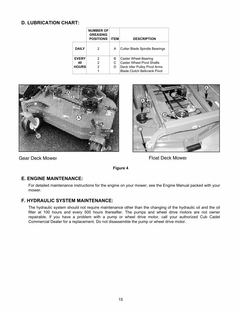
D. LUBRICATION CHART: NUMBER OF GREASINGPOSITIONS ITEM DESCRIPTION
DAILY 2 A Cutter Blade Spindle Bearings
EVERY 40
HOURS
2221
BCD
Caster Wheel BearingCaster Wheel Pivot ShaftsDeck Idler Pulley Pivot ArmsBlade Clutch Bellcrank Pivot
Float Deck MowerGear Deck Mower
Figure 4
E. ENGINE MAINTENANCE:For detailed maintenance instructions for the engine on your mower, see the Engine Manual packed with your mower.
F. HYDRAULIC SYSTEM MAINTENANCE:The hydraulic system should not require maintenance other than the changing of the hydraulic oil and the oil filter at 100 hours and every 500 hours thereafter. The pumps and wheel drive motors are not owner repairable. If you have a problem with a pump or wheel drive motor, call your authorized Cub Cadet Commercial Dealer for a replacement. Do not disassemble the pump or wheel drive motor.
15

G. MOWER MAINTENANCE 1. TO CHANGE A BLADE:
a. Remove the deck cover.b. Tip the mower back and block up the front of the deck. See Figure 5.c. Place one wrench on the hex head bolt under the blade. Use a second wrench to remove the nut
on top of the spindle pulley.d. Remember the number of blade spacers both above and below the spindle.e. Remove the long (5/8" x 9-1/2") blade bolt for fixed decks and (3/4" x 7") blade bolt for float decks,
the flat washer, the blade and the blade spacers. (Note: torque the 5/8"bolt 70-80 ft.lbs. and the 3/4" bolt 90-115 ft.lbs.)
Figure 5 48" Cutting Deck Shownf. To replace the blade, reverse the above procedure. Be careful to replace the blade spacers
correctly above and below the spindle.
2. TO CHANGE THE BLADE DRIVE BELTS:a. Make sure the blade clutch is disengaged.b. Remove the deck cover.c. Remove the nut and the cap screw which serves as a belt guide and is mounted in the idler pulley
arm. See Figure 6.
Figure 6
16
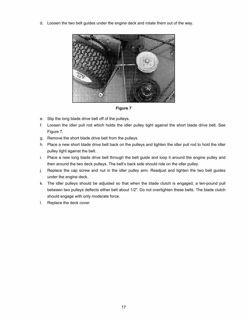
d. Loosen the two belt guides under the engine deck and rotate them out of the way.
Figure 7
e. Slip the long blade drive belt off of the pulleys.f. Loosen the idler pull rod which holds the idler pulley tight against the short blade drive belt. See
Figure 7.g. Remove the short blade drive belt from the pulleys.h. Place a new short blade drive belt back on the pulleys and tighten the idler pull rod to hold the idler
pulley tight against the belt.i. Place a new long blade drive belt through the belt guide and loop it around the engine pulley and
then around the two deck pulleys. The belt’s back side should ride on the idler pulley.j. Replace the cap screw and nut in the idler pulley arm. Readjust and tighten the two belt guides
under the engine deck.k. The idler pulleys should be adjusted so that when the blade clutch is engaged, a ten-pound pull
between two pulleys deflects either belt about 1/2". Do not overtighten these belts. The blade clutch should engage with only moderate force.
l. Replace the deck cover.
17
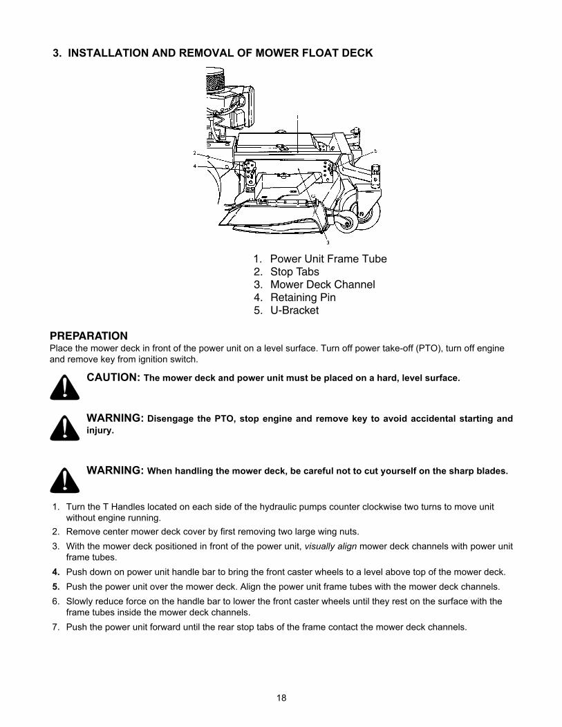
3. INSTALLATION AND REMOVAL OF MOWER FLOAT DECK
1. Power Unit Frame Tube2. Stop Tabs3. Mower Deck Channel4. Retaining Pin5. U-Bracket
PREPARATION Place the mower deck in front of the power unit on a level surface. Turn off power take-off (PTO), turn off engine and remove key from ignition switch.
CAUTION: The mower deck and power unit must be placed on a hard, level surface.
WARNING: Disengage the PTO, stop engine and remove key to avoid accidental starting and injury.
WARNING: When handling the mower deck, be careful not to cut yourself on the sharp blades.
1. Turn the T Handles located on each side of the hydraulic pumps counter clockwise two turns to move unit without engine running.
2. Remove center mower deck cover by first removing two large wing nuts. 3. With the mower deck positioned in front of the power unit, visually align mower deck channels with power unit
frame tubes. 4. Push down on power unit handle bar to bring the front caster wheels to a level above top of the mower deck. 5. Push the power unit over the mower deck. Align the power unit frame tubes with the mower deck channels. 6. Slowly reduce force on the handle bar to lower the front caster wheels until they rest on the surface with the
frame tubes inside the mower deck channels. 7. Push the power unit forward until the rear stop tabs of the frame contact the mower deck channels.
18
INSTALLING THE MOWER DECK
WARNING: Disengage PTO, stop engine and remove key to avoid accidental starting and injury.
WARNING: When handling the mower deck, be careful not to cut yourself on the sharp blades.
1. Lift one side of the mower deck to achieve the desired cutting height. 2. Push the button in the center of the handle of each of the retaining pins to insert the retaining pins through the
appropriate front and rear height adjustment holes in the mower deck channel. Select the lowest holes that allow insertion of the pins just above the bottom inside edge of the power unit frame U-brackets inside the brackets.
NOTE: The same height adjustment hole must be used for both front and rear pin installation. 3. Release the mower deck. 4. Repeat the above procedure to install the other side of the mower deck.
NOTE: The same height adjustment hole must be used for all four pin installations. 5. Adjust the mower deck as required. Refer to “Adjustments” in your Operator’s Manual. 6. Install the PTO belt by executing the following procedures:
1. Remove center mower deck cover by first removing two large wing nuts.2. Push against idler arm to release tension on the PTO belt. For increased leverage, a 3/8-inch square
drive of a breaker bar can be placed in the 3/8-inch square hole of the idler arm. The breaker bar han-dle can be pushed to release tension on the PTO belt.
NOTE: Be sure the narrow side of the belt is in the bottom of the pulley grooves.3. Carefully remove old PTO belt, and replace it with a new belt.4. Release force on the idler arm to restore tension to new PTO belt. If used, remove breaker bar from
idler arm.5. Replace center mower deck cover and secure it in place with two large wing nuts.
NOTE: Ensure that the center mower deck cover is replaced and secured with the two large wing nuts.7. Turn the T Handles on each side of the hydraulic pumps clockwise two turns to shut the valves. (CAUTION
DO NOT OVERTIGHTEN.
19

REMOVING THE MOWER DECK
WARNING: Disengage PTO, stop engine and remove key to avoid accidental starting and injury.
WARNING: When handling the mower deck cover, be careful not to cut yourself on the sharp blades.
1. Remove the center mower deck cover by first removing the two large wing nuts. 2. Remove the PTO belt. 3. Lift one side of the mower deck. 4. Push the button in the center of the handle of each of the two retaining pins supporting this side of the mower
deck. Remove the pins. 5. Lower this side of the mower deck until the ball wheels rest on the surface. 6. Repeat steps 3 through 5 for the other side of the mower deck. 7. Turn the T handles located on the side of each hydraulic pump counterclockwise two turns to move the unit
without engine running. 8. Push down on the power unit handle bar to bring the front caster wheels to a level above the top of the mower
deck. 9. Pull the power unit backwards, free of the mower deck. Slowly reduce force on the handle bar to lower the
front caster wheels until they rest on the surface.
20

4. TO CHANGE THE PUMP DRIVE BELT: See Figure 8.a. Make sure the blade clutch is disengaged.
Figure 8 b. Working under the engine deck, take the long blade drive belt off of the engine pulley.c. Loosen the locknut holding the pump drive belt idler pulley in place and slide the pulley away from
the pump drive belt.d. Remove the old belt and mount a new belt on the pulleys.e. Slide the idler pulley back onto the belt and tighten the locknut holding it in place. The idler pulley
should be adjusted so that a five-pound pull on the belt between the engine pulley and the pump pulleys deflects the belt about 3/16".
f. Replace the long blade drive belt on the engine pulley.
5. TO CHANGE A SPINDLE ASSEMBLYa. Make sure the blade clutch is disengaged.b. Remove the deck cover or covers.c. Remove the blade.d. Remove the blade drive belts.e. Remove the two bolts which hold the pulley bushing tight in the spindle pulley and thread the bolts
into the other two holes in the bushing. (For float deck mowers, skip to “i” ).f. Alternately turn each bolt 1/2 turn clockwise until the bolts force the pulley off of the bushing.g. Remove the bushing by tapping a large screw driver into the slot in the side of the bushing. h. Remove the key from the spindle.i. Tip the mower back and block up the front of the deck.j. Remove the bolts and locknuts (four for fixed and three for float decks) holding the spindle
assembly to the deck.k. Remove the spindle assembly.
21
SECTION 9: REPLACEMENT PARTS
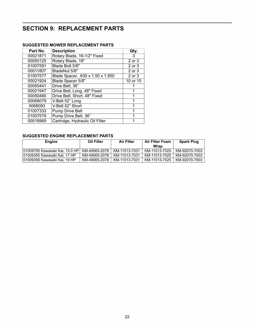
SUGGESTED MOWER REPLACEMENT PARTS
22
Part No. Description Qty.00021871 Rotary Blade, 16-1/2" Fixed 3 00050125 Rotary Blade, 18" 2 or 301007591 Blade Bolt 5/8" 2 or 3 00011807 BladeNut 5/8" 2 or 301007577 Blade Spacer, .630 x 1.50 x 1.850 2 or 300021924 Blade Spacer 5/8" 10 or 1500050441 Drive Belt, 36” 100021947 Drive Belt, Long, 48" Fixed 100050480 Drive Belt, Short, 48" Fixed 100068079 V-Belt 52” Long 10068093 V-Belt 52” Short 101007333 Pump Drive Belt 101007579 Pump Drive Belt, 36” 100018969 Cartridge, Hydraulic Oil Filter 1
SUGGESTED ENGINE REPLACEMENT PARTS
Engine Oil Filter Air Filter Air Filter FoamWrapSpark Plug
01009795 Kawasaki Kai, 15.0 HP KM-49065-2078 KM-11013-7031 KM-11013-7025 KM-92070-700301009355 Kawasaki Kai, 17 HP KM-49065-2078 KM-11013-7031 KM-11013-7025 KM-92070-700301009356 Kawasaki Kai, 19 HP KM-49065-2078 KM-11013-7031 KM-11013-7025 KM-92070-7003

Do not m
ow on inclines w
ith a slope in excess of 15 degrees (a rise of approximately 2-1/2 feet every 10 feet). A
riding mow
er could overturn and cause serious injury. If operating a w
alk-behind mow
er on such a slope, it is extremely difficult to m
aintain your footing and you could slip, resulting in serious injury.O
perate ZER
O-TU
RN
mow
ers across the face of slopes, never up and down slopes.
Operate W
ALK
-BE
HIN
D m
owers across the face of slopes, never up and dow
n slopes.
WA
RN
ING
15°
SIG
HT A
ND
HO
LD TH
IS LE
VE
L WITH
A V
ER
TICA
L TRE
E
A P
OW
ER
PO
LE
A C
OR
NE
R O
F A B
UILD
ING
OR
A FE
NC
E P
OS
T
FOLD
ON
DO
TTED LIN
E, REPR
ESENTIN
G A 15° SLO
PE
USE TH
IS PAG
E AS A
GU
IDE TO
DETER
MIN
E SLOPES W
HER
E YOU
MA
Y NO
T OPER
ATE SA
FELY.
SLOPE GAUGE
23

Cub Cadet LLC - P.O. Box 361131, Cleveland, Ohio 44136-0019; Phone 1-877-282-8684
MANUFACTURER’S LIMITED WARRANTY FOR CUB CADET COMMERCIAL
WIDE AREA WALK-BEHIND COMMERCIAL MOWER
IMPORTANT: To obtain warranty coverage owner may be required present proof of purchase and applicable maintenance records to the servicing dealer. Please see the operator’s manual for information on required maintenance and service intervals. In addition, Cub Cadet may deny warranty coverage if the hour meter, or any part thereof, is altered, modified, disconnected or otherwise tampered with.
The limited warranty set forth below is given by Cub Cadet LLC with respect to new merchandise used for commercial and related purposes purchased and used in the United States and/or its territories and possessions, and by MTD Products Limited with respect to new merchandise purchased and used in Canada and/or its territories and possessions (either entity respectively, “Cub Cadet”).
Cub Cadet warrants this product (excluding its No-Fault Components,
and Batteries as described below) against defects in material and workmanship for a period of two (2) years from the date of original retail purchase or lease and will, at its option, repair or replace, free of charge, any part found to be defective in materials or workmanship.
Batteries have a one-year prorated limited warranty against defects in material and workmanship, with 100% replacement during the first three months. After three months, the battery replacement credit is based on the months remaining in the twelve (12) month period dating back to the original date of original sale or lease. Any replacement battery will be warranted only for the remainder of the original warranty period.
No-Fault Components include only belts, tires, seats and grass bags which are warranted to be free from defects in material and workmanship for a period of thirty (30) days from the date of original purchase or lease.
HOW TO OBTAIN SERVICE: Warranty service is available, WITH PROOF OF PURCHASE AND APPLICABLE MAINTAINCE RECORDS, through your local authorized service dealer. To locate the dealer in your area; In the U.S.A.:Check your Yellow Pages, or contact Cub Cadet LLC at P.O. Box 361131, Cleveland, Ohio 44136-0019, or call 1-877-282- 8684, or log on to our Web site at www.cubcadetcommercial.com.In Canada:For all provinces excluding Quebec contact Modern Power Products d/o MTD Canada Ltd. At 60 Ottawa Street South, Kitchener, Ontario N2G 3S7 or call 1-800-567-6775 or log on to our website at www.cubcadet.ca.
In Quebec contact Les Distributions RVI Ltee. d/o MTD Canada Ltd. 2955 jean-Baptiste Deschamps, Ville Lachine, Quebec H8T 1C5 or call 1-800-361-5770 or log on to our website at www.cubcadet.info.
This limited warranty does not provide coverage in the following cases: a. Routine maintenance items such as lubricants, filters, blade
sharpening, tune-ups, brake adjustments, clutch adjustments, deck adjustments, and normal deterioration of the exterior finish due to use or exposure.
b. Service completed by someone other than an authorized service dealer.
c. For products sold or exported outside of the United States and/or Canada, and their respective possessions and territories, except those sold through Cub Cadet’s authorized channels of export distribution.
d. Damage or failure resulting from the use of defective or improper peplacement parts and\or accessories other than genuine Cub Cadet parts.
e. Transportation charges and service calls. f. Failure to operate and maintain the product in accordance with
the Operator’s Manual furnished with the product, g. Damages and failures resulting from misuse, abuse, neglect,
accident, improper maintenance, alteration, vandalism, theft, fire, water, or damage because of other peril or natural disaster.
There are no implied warranties, including without limitation any implied warranty of merchantability or fitness for a particular purpose. No warranties shall apply after the applicable period of express written warranty above. No other express warranties beyond those mentioned above, given by any person or entity, including a dealer or retailer, with respect to any product, shall bind Cub Cadet. The exclusive remedy is repair or replacement of the product as set forth above. The terms of this warranty provide the sole and exclusive remedy arising from the sale and/or lease of the products covered hereby. Cub Cadet shall not be liable for any incidental or consequential loss or damage including, without limitation, expenses incurred for substitute or replacement lawn care services or for rental expenses to temporarily replace a warranted product.
Some jurisdictions do not allow the exclusion or limitation of incidental or consequential damages, or limitations on how long an implied warranty lasts, so the above exclusions or limitations may not apply to you. This limited warranty gives you specific legal rights, and you may also have other rights that vary in different jurisdictions.
In no event shall recovery of any kind be greater than the amount of the purchase price of the product sold. Alteration of safety features of the product shall void this warranty. You assume the risk and liability for loss, damage, or injury to you and your property and/or to others and their property arising out of improper use, misuse or inability to use the product. This limited warranty shall not extend to anyone other than the original purchaser/Leasee or to the person for whom it was purchased or leased as a gift.
Form No. 01008314 Rev. 08-1 03/10/2008