Embed Size (px)
Citation preview
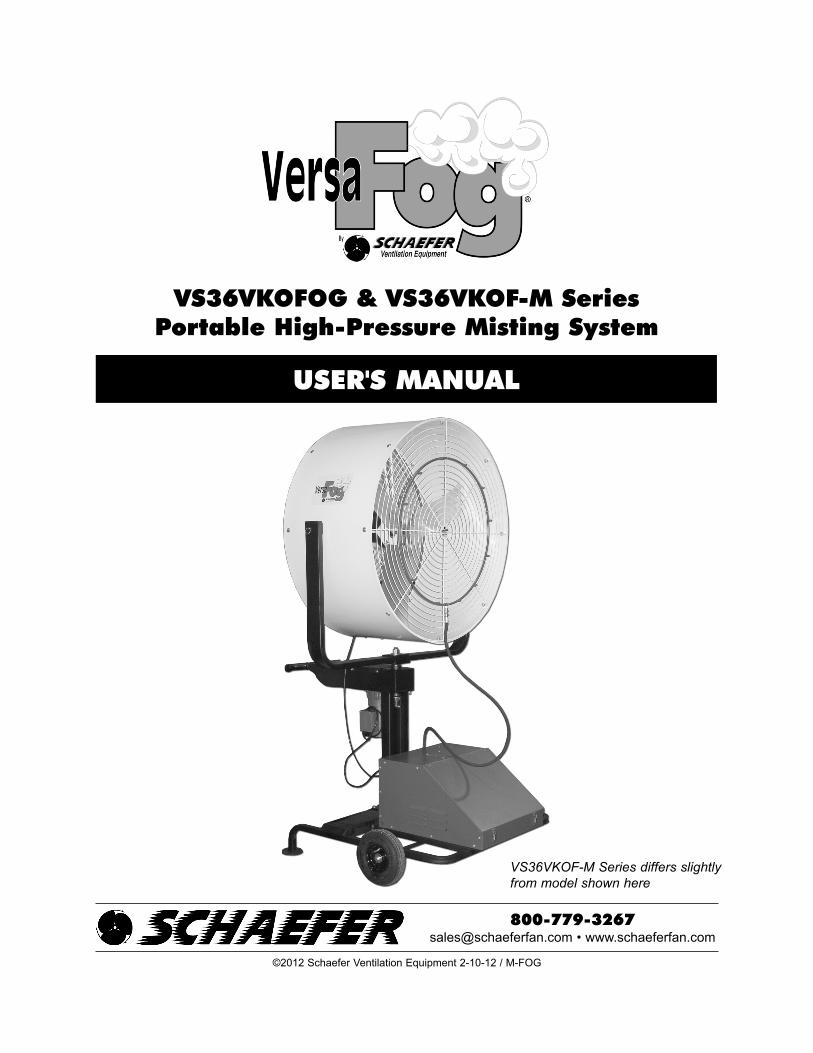
VS36VKOFOG & VS36VKOF-M SeriesPortable High-Pressure Misting System
USER'S MANUAL
[email protected] • www.schaeferfan.com
©2012 Schaefer Ventilation Equipment 2-10-12 / M-FOG
VS36VKOF-M Series differs slightly
from model shown here
INTRODUCTION ............................................................................................................................2
SAFETY..........................................................................................................................................3
FAN AND MIST RING SPECIFICATIONS ....................................................................................3
MIST PUMP SPECIFICATIONS ....................................................................................................4
OSCILLATING GEAR MOTOR AND POWER CORD SPECIFICATIONS....................................5
ASSEMBLY INSTRUCTIONS ................................................................................................5, 6, 7
START-UP / OPERATION ..........................................................................................................8, 9
MAINTENANCE ....................................................................................................................10, 11
TROUBLESHOOTING ................................................................................................................12
REPLACEMENT PARTS..............................................................................................................13
WARRANTY ................................................................................................................................14
Index
Thank You!
2
The employees of Schaefer Ventilation Equipment would like to thank you for your recent Schaefer purchase. If a problem
should arise, your Schaefer dealer can supply the necessary information to help you.
This manual is designed to provide comprehensive safety, set up and operation, maintenance, troubleshooting, parts listing
and warranty information. To order replacement parts contact the dealer from whom you purchased your VersaFog®. If you
do not have that information, please call Schaefer Ventilation Equipment at 800-779-3267 to locate a dealer near you.
The cool air you will now enjoy when using this misting equipment is created through the process of evaporation. Heat is
required to change water from a liquid to a gas or water vapor. Our high-pressure misting equipment creates a very fine fog
by pumping high pressure water at a very low flow rate through small nozzles. When combined with the air provided by a
fan, this fog is rapidly evaporated. The heat required to evaporate the fog is extracted from the air causing a reduced air
temperature. This cooler air is then distributed to people or animals creating a direct cooling effect and will also gradually
replace warmer, saturated air from enclosed spaces.
The performance of your misting system can be affected by local conditions. Using this equipment for any other purpose
than it was intended or in a way not within the operating recommendations specified in this manual will void the warranty
and may cause personal injury. All information, illustrations and specifications in this manual are based on the latest
product information available at the time of printing. We reserve the right to make changes at any time without notice.
Keep this manual in a clean, dry place for future reference.
Thank you again, and stay cool!
3
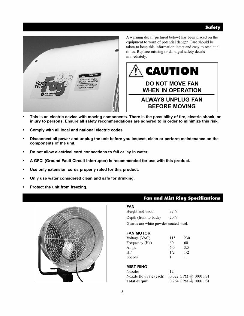
Safety
A warning decal (pictured below) has been placed on the
equipment to warn of potential danger. Care should be
taken to keep this information intact and easy to read at all
times. Replace missing or damaged safety decals
immediately.
• This is an electric device with moving components. There is the possibility of fire, electric shock, or injury to persons. Ensure all safety recommendations are adhered to in order to minimize this risk.
• Comply with all local and national electric codes.
• Disconnect all power and unplug the unit before you inspect, clean or perform maintenance on the components of the unit.
• Do not allow electrical cord connections to fall or lay in water.
• A GFCI (Ground Fault Circuit Interrupter) is recommended for use with this product.
• Use only extension cords properly rated for this product.
• Only use water considered clean and safe for drinking.
• Protect the unit from freezing.
CAUTIONDO NOT MOVE FAN
WHEN IN OPERATION
ALWAYS UNPLUG FAN
BEFORE MOVING
Fan and Mist Ring Specifications
FAN
Height and width 371/2"
Depth (front to back) 201/2"
Guards are white powder-coated steel.
FAN MOTOR
Voltage (VAC) 115 230
Frequency (Hz) 60 60
Amps 6.0 3.5
HP 1/2 1/2
Speeds 1 1
MIST RING
Nozzles 12
Nozzle flow rate (each) 0.022 GPM @ 1000 PSI
Total output 0.264 GPM @ 1000 PSI

4
Mist Pump Specifications
The pump assembly includes a pump, motor and control
assembly designed to provide high-pressure water supply
to the mist ring. The assembly is housed in a galvanized
steel enclosure with a blue, textured powder-coat finish.
The enclosure is mounted on a tubular-steel cart with two
eight-inch all-terrain pneumatic wheels for ease of mobility
on any surface. Two stainless steel latches enable easy
access to the interior components via the hinged lid.
The pump assembly includes an automatic low-pressure
shutoff; the pump will not operate without water pressure.
MIST PUMP AND MOTOR
Voltage (VAC) 115 208-230
Frequency (Hz) 60 60
Amps 8.7 4.4
HP 3/4 3/4
Pump output .75 GPM @ 1000 PSI
Filter 5 micron polypropylene
Water supply 15 PSI min.; 75 PSI max.
pressure and flow 1 GPM minimum
POTABLE ONLY
Pump crankcase oil CAT® brand oil or 30 weight
hydraulic oil
REAR VIEWTOP INSIDE VIEW
FEATURES• Die cast flange-style aluminum crankcase means high strength, lightweight, and excellent
tolerance control.
• Heavy-duty dual crankshaft bearings provide extended drive-end life.
• Chrome-moly crankshaft provides unmatched strength and surface hardness for long life.
• High strength connecting rods assure durability and bearing quality.
• Strong chrome plated brass plunger rods with chrom-moly crosshead pins.
• Special, concentric, high-density, polished solid ceramic plungers provide a true wear surface and
extended seal life.
• High tensile strength, forged brass manifold head with built-in integral regulator and eight
mounting screws for exceptional strength.
• 100% wet seal design adds to service life by allowing pumped liquids to cool and lubricate on
both sides.
• Stainless steel valves, seats and springs provide corrosion-resistance, ultimate seating and
extended life.
• Unique design and specially formulated Hi-Pressure Seals offer unmatched performance and seal life.
• Crossheads are 360° supported for uncompromising alignment.
The Pumps with Nine Lives
WARNINGELECTRICAL SHOCK HAZARD
• Serious injury or death is possible.
• Use a receptacle protected by a
Ground Fault Circuit Interrupter (GFCI).
5
Assembly Instructions
STEP 1 - REMOVE SHIPPING OIL PLUG
1. Remove mist pump assembly from carton and place
on a level surface.
2. Release the two latches on the front of the enclosure
and lift the hinged lid.
3. The pump has been pre-filled with crankcase oil at
the factory.
CAUTIONThe plastic shipping plug must be removed
before operating the mist pump.
4. Remove the label and small plastic oil plug from the
pump and save for future transportation use.
STEP 2 - ASSEMBLE PUMP TO BASE
TOOLS REQUIRED: Two 7/16" wrenches.
1. Place base on a level surface.
2. Remove four bolts and flange lock nuts from base.
3. Place pump assembly on base. Be sure the pump
assembly is oriented so the back of it faces the
footpads on the base. Insert the four bolts to secure
the pump to the base.
STEP 2
FRONT BACK
STEP 1
Oscillating Gear Motor and Power Cord Specifications
OSCILLATING GEAR MOTOR (unit includes one of the following)
GM36VKO-DV 1/100 HP 115/208-230 V .29/.17 A 2.7 RPM
GM-OSC-HT 90 in-lb 115 V 60 Hz 1.2 A 2 RPM
GM-OSC-HT-A 90 in-lb 220 V 50/60 hZ .62 A 2 RPM
POWER CORD
25' outdoor-rated power cord with integrated GFCI.
115 V - 16/3 SJOOW cord includes 20 Amp NEMA 5-20P plug which requires a NEMA 5-20R receptacle.
220 V - 14/3 SJO cord does not include plug.
6
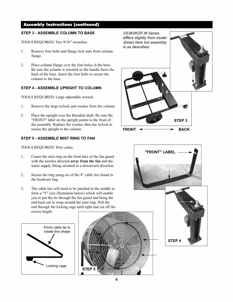
Assembly Instructions (continued)
STEP 3 - ASSEMBLE COLUMN TO BASE
TOOLS REQUIRED: Two 9/16" wrenches.
1. Remove four bolts and flange lock nuts from column
flange.
2. Place column flange over the four holes in the base.
Be sure the column is oriented so the handle faces the
back of the base. Insert the four bolts to secure the
column to the base.
STEP 4 - ASSEMBLE UPRIGHT TO COLUMN
TOOLS REQUIRED: Large adjustable wrench.
1. Remove the large nylock and washer from the column.
2. Place the upright over the threaded shaft. Be sure the
"FRONT" label on the upright points to the front of
the assembly. Replace the washer, then the nylock to
secure the upright to the column.
STEP 5 - ASSEMBLE MIST RING TO FAN
TOOLS REQUIRED: Wire cutter.
1. Center the mist ring on the front face of the fan guard
with the nozzles directed away from the fan and the
water supply fitting oriented in a downward direction.
2. Secure the ring using six of the 4" cable ties found in
the hardware bag.
3. The cable ties will need to be pinched in the middle to
form a "V" (see illustration below) which will enable
you to put the tie through the fan guard and bring the
end back out to wrap around the mist ring. Pull the
end through the locking cage until tight and cut off the
excess length.
STEP 3
FRONT BACK
"FRONT" LABEL
Pinch cable tie to
create this shape
Locking cage
STEP 4
STEP 5
VS36VKOF-M Series
differs slightly from model
shown here but assembly
is as described.
7
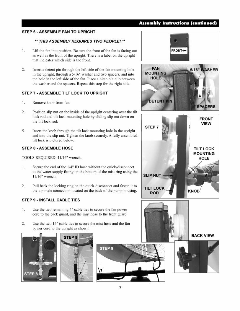
STEP 6 - ASSEMBLE FAN TO UPRIGHT
** THIS ASSEMBLY REQUIRES TWO PEOPLE! **
1. Lift the fan into position. Be sure the front of the fan is facing out
as well as the front of the upright. There is a label on the upright
that indicates which side is the front.
2. Insert a detent pin through the left side of the fan mounting hole
in the upright, through a 5/16" washer and two spacers, and into
the hole in the left side of the fan. Place a hitch pin clip between
the washer and the spacers. Repeat this step for the right side.
STEP 7 - ASSEMBLE TILT LOCK TO UPRIGHT
1. Remove knob from fan.
2. Position slip nut on the inside of the upright centering over the tilt
lock rod and tilt lock mounting hole by sliding slip nut down on
the tilt lock rod.
5. Insert the knob through the tilt lock mounting hole in the upright
and into the slip nut. Tighten the knob securely. A fully assembled
tilt lock is pictured below.
STEP 8 - ASSEMBLE HOSE
TOOLS REQUIRED: 11/16" wrench.
1. Secure the end of the 1/4" ID hose without the quick-disconnect
to the water supply fitting on the bottom of the mist ring using the
11/16" wrench.
2. Pull back the locking ring on the quick-disconnect and fasten it to
the top male connection located on the back of the pump housing.
STEP 9 - INSTALL CABLE TIES
1. Use the two remaining 4" cable ties to secure the fan power
cord to the back guard, and the mist hose to the front guard.
2. Use the two 14" cable ties to secure the mist hose and the fan
power cord to the upright as shown.
Assembly Instructions (continued)
FRONT
STEP 8
STEP 9
STEP 9
KNOB
SLIP NUT
TILT LOCK
ROD
TILT LOCK
MOUNTING
HOLE
DETENT PIN
FAN
MOUNTING
HOLE
5/16" WASHER
SPACERS
FRONT
VIEW
BACK VIEW
STEP 7

8
Start-Up / Operation
To begin the start-up procedure, the power cord must be
disconnected from the electrical supply. You will also want to
ensure that the ball valve on the back of the unit is in the closed
position.
STEP 1 - WATER SUPPLY
Connect a 1/2" or larger water supply line or hose to the valve on
the back of the enclosure. Make certain that the following water
supply conditions are met:
• Supply pressure of 15-75 PSI
• Constant minimum flow rate of 1 GPM
• Water pH of less than 7.5
• Total dissolved solids content of less than 500 PPM
Fluctuating water supply can cause cavitations in mist pump
resulting in permanent damage.
Use only stainless steel, copper or brass pipe and hardware
to plumb the water supply. Black or galvanized steel
plumbing parts will corrode, creating particulate that can
plug nozzles.
Excessively hard (high solids) water can plug nozzles.
A plugged filter caused by poor quality water can restrict
flow to pump causing permanent damage.
Never operate pump without water supply.
Do not close off system completely on discharge side of
pump when operating at high pressures (greater than water
supply pressure). Always provide flow to at least four
nozzles while operating pump.
CAUTION
WARNINGELECTRICAL SHOCK
HAZARD
PINCH HAZARD
TRIP HAZARD
• Serious injury or death is possible.
• Plug these units into properly
grounded receptacles only.
• Receptacles on pump base are live
when main power cord is plugged
in.
• Do not operate fans without
guards in place.
• Do not insert anything into fan
guard while fan is operating.
• Position cords and hoses to lie
flat on the ground or floor.
Assembly Instructions (continued)
STEP 9 - ELECTRICAL CONNECTIONS
There are two standard electrical outlets located on the back of
the pump housing.
NOTE: Receptacles on pump base are live when main power
cord is plugged in.
Plug the power cord from the oscillator motor into one of the
outlets. Plug the power cord from the fan into the pigtail cord
pulled through the large hole in the back of the pump housing.
PIGTAIL CORD
(INSIDE HOUSING)
LARGE HOLE IN HOUSING
OSCILLATOR CORD
FAN
POWER
CORD
ROCKER SWITCH OPERATION
UP = FAN ONLY (OUTLETS ON)
MIDDLE = OFF (OUTLETS OFF)
DOWN = FAN / MIST (OUTLETS ON)

9
Start-Up / Operation (continued)
STEP 2 - START-UP AND VENTING
1. At first use, air may be entrained in the internal hoses and pump chambers. This will prevent the system from pressurizing properly. You may experience motor and pump operation with minimal or no misting.
2. With the GFCI power cord inserted into a properly grounded power supply receptacle and the pressurized water supply open to the unit, move the rocker switch to the FAN/MIST position.
3. Flush the mist ring (without nozzles) to remove dust and particles from manufacturing.
4. Move the rocker switch to the OFF position and unplug the main power cord.
5. Insert the nozzles into the mist ring. No tools should be used - HAND TIGHTEN ONLY.
6. Plug the main power cord into a properly grounded receptacle, and move the rocker switch to the FAN/MIST position.
7. Turn the regulator hex cap clockwise (by hand) until the pressure on the gauge reads approximately 1000 PSI.
CAUTIONDO NOT RAISE SYSTEM PRESSURE ABOVE 1000 PSI.DAMAGE TO INTERNAL COMPONENTS COULDOCCUR.
8. If the system fails to pressurize, open the ball valve slightly, allowing a small amount of water to escape.
9. Continue this until pressurization occurs, then close the valve. This may take several minutes. Open the valve further if necessary.
10. Close and latch lid for operation.
STEP 3 - FAN OPERATION
For best results, always attempt to place the fan in an upwindposition (fan blowing in same direction as wind) when misting.
Never allow the "fog" from the nozzles to come in contact withsurfaces. This will cause condensation and water will form onthose surfaces. Redirect the fan to prevent this circumstance.
REGULATOR HEX CAP
PRESSURE GAUGE
BALL VALVE
WARNINGELECTRICAL SHOCK
HAZARD
• Serious injury or death is possible.
• Only connect power supply
(GFCI) plug to a properly
grounded (bonded) receptacle.
PRESSURE SWITCH SCREW
A NOTE ABOUT THE PRESSURE SWITCH SCREW
The pressure switch screw has been set at the factory. If
it needs to be adjusted, the correct position of the screw
is flush with the housing.
10
Maintenance
PUMP
The pump's crankcase was filled with oil at the factory.
This initial oil fill should be replaced after approximately
50 hours of operation. It should be changed every 500
hours of operation or every three months thereafter.
Use only CAT® brand oil or 30 weight hydraulic oil.
The oil level in the pump can be read on the site glass at
the end of the pump. The level should always be
maintained so that it is touching the red dot on the center
of the site glass.
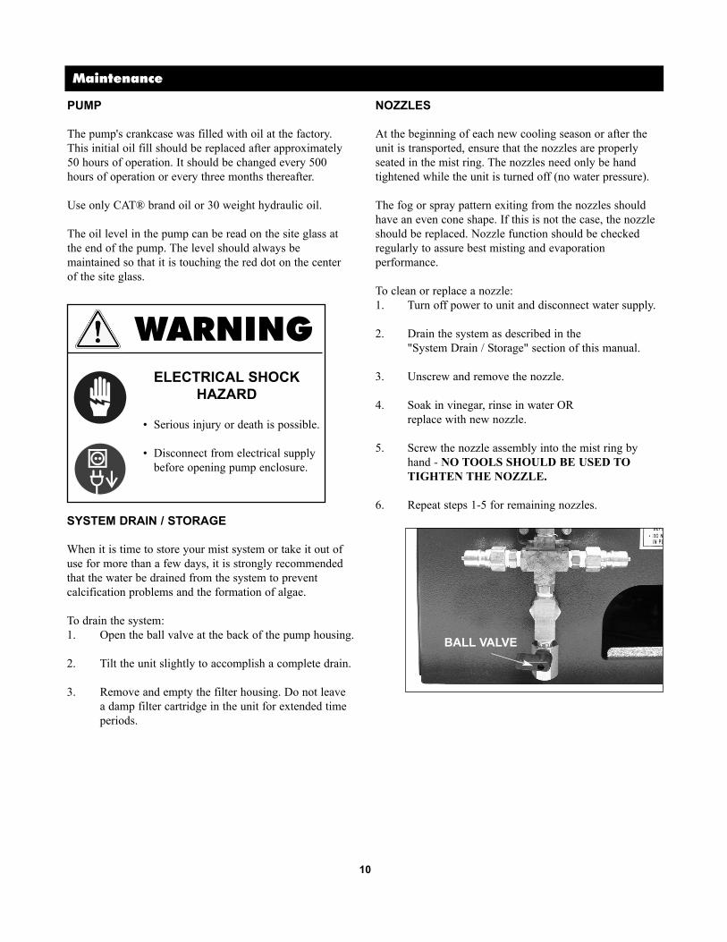
SYSTEM DRAIN / STORAGE
When it is time to store your mist system or take it out of
use for more than a few days, it is strongly recommended
that the water be drained from the system to prevent
calcification problems and the formation of algae.
To drain the system:
1. Open the ball valve at the back of the pump housing.
2. Tilt the unit slightly to accomplish a complete drain.
3. Remove and empty the filter housing. Do not leave
a damp filter cartridge in the unit for extended time
periods.
NOZZLES
At the beginning of each new cooling season or after the
unit is transported, ensure that the nozzles are properly
seated in the mist ring. The nozzles need only be hand
tightened while the unit is turned off (no water pressure).
The fog or spray pattern exiting from the nozzles should
have an even cone shape. If this is not the case, the nozzle
should be replaced. Nozzle function should be checked
regularly to assure best misting and evaporation
performance.
To clean or replace a nozzle:
1. Turn off power to unit and disconnect water supply.
2. Drain the system as described in the
"System Drain / Storage" section of this manual.
3. Unscrew and remove the nozzle.
4. Soak in vinegar, rinse in water OR
replace with new nozzle.
5. Screw the nozzle assembly into the mist ring by
hand - NO TOOLS SHOULD BE USED TO
TIGHTEN THE NOZZLE.
6. Repeat steps 1-5 for remaining nozzles.
WARNINGELECTRICAL SHOCK
HAZARD
• Serious injury or death is possible.
• Disconnect from electrical supply
before opening pump enclosure.
BALL VALVE

11
Maintenance (continued)
FILTER
Filter maintenance requirements will change with changing water
conditions. The filter cartridge should be inspected frequently and
changed as needed. A dirty filter will restrict water flow to the
pump and can cause permanent damage.
To change the filter cartridge:
1. Turn off and disconnect water supply.
2. Disconnect unit from electrical supply.
3. Open pump enclosure.
4. Unscrew blue filter housing from black bracket.
NOTE: When opening the filter housing, it is common for
the O-ring to lift out of housing and stick to cap.
5. Remove used cartridge and discard. Rinse out housing and
fill 1/3 full of water. Add two to three tablespoons of
bleach and scrub thoroughly with brush. Rinse thoroughly.
6. Remove O-ring from housing and wipe groove and O-ring
clean. Lubricate O-ring with a coating of clean silicone
grease. Place O-ring back in place and press down into the
groove.
NOTE: This step is important to ensure proper filter seal.
Make sure the O-ring is seated level in the groove.
7. Insert a new cartridge into the housing, making sure that it
slips down over the sump standpipe.
8. Screw the housing onto the bracket and hand tighten.
DO NOT OVER TIGHTEN.
9. Turn on the water supply slowly to allow filter housing to
fill with water.
10. Check for leaks.
11. Close the cover.
WARNINGELECTRICAL SHOCK
HAZARD
• Serious injury or death is possible.
• Disconnect from electrical supply
before opening pump enclosure.
RUBBER O-RING
FILTER CARTRIDGE
FILTER HOUSING

12
Troubleshooting
SYMPTOM
Low pressure.
Pump is on but mist ring is not
working.
Water sprays from nozzles
after system is turned off.
Pump stops running.
POTENTIAL CAUSE(S) CORRECTIVE ACTION
1. Replace nozzle.
2. Tighten fittings and hoses.
3. Check with new gauge.
4. Replace filter.
5. Replace discharge hose.
6. Comfirm that supplied water pressure is
between 15-75 PSI.
1. Worn nozzle.
2. Air leak in inlet plumbing.
3. Pressure gauge inoperative
or not registering accurately.
4. Filter clogged.
5. Leaky discharge hose.
6. Inadequate water supply.
1. Pressure regulator turned low.
2. There may be a leak in the
system.
3. There may be an air lock.
1. Turn pressure regulator clockwise to
increase pressure.
2. Confirm that nozzles are intact. Check for
loose hose fitting in manifold line.
3. Follow pump venting instructions in this
manual.
1. Pressure may not be
completely bled from system.
1. Allow pressure to bleed slowly while
running fan.
1. Power supply interrupted.
2. Circuit breaker switched off.
3. Low-pressure switch activated.
4. Pump motor overheated.
5. GFCI is tripped.
1. Restore power.
2. Confirm breaker is not being overloaded or
is worn.
3. Confirm inlet water supply is still on and
is 15-75 PSI.
Inspect filters and replace if required.
Water supply being shared can reduce water
pressure.
Confirm low-pressure switch control wires
are intact.
4. Never operate pump above 1000 PSI.
Confirm proper ventilation is available to
pump motor.
Confirm voltage and that motor is within
service factor.
Low-pressure sensor tripping motor on and
off. Check water pressure is 15-75 PSI.
5. Press RESET button on GFCI.
Knocking noise. 1. Inadequate water supply. 1. Ensure that correct inlet water pressure is
supplied, especially at system start-up.
Nozzle(s) leaking during
operation.
1. Nozzle not tightened. 1. With unit turned off (i.e. no water pressure),
hand tighten nozzle(s).
Nozzle does not spray water. 1. Nozzle clogged or broken. 1. Clean or replace nozzle.
Oscillator does not run. 1. Not plugged into pump
enclosure.
2. Defective switch.
3. Defective gear motor.
1. Ensure oscillator is plugged into outlet on
pump enclosure.
2. (115V) Plug oscillator directly into a wall
outlet. If oscillator works replace switch.
3. (115V) If oscillator does not run while
plugged into the wall outlet, ensure all
wiring connections are secure - if oscillator
still does not run, replace oscillator motor.

13
Replacement Parts
REPLACEMENT PARTS
P/N DESCRIPTION 115V 230V
BN8-1224 Brass nozzle .008 orifice 12 12
0HANDLEGRIP Finger lugged grip - 1" 2 2
CS237 Pump motor, 3/4 HP 115/208-230V 1 1
PUMP.75C Pump, direct-drive plunger 1 1
VKF-FILTERCART Filter cartridge, 5 micron, 4 7/8" 1 1
VKF-FILTERHOUS Filter housing, 5" 1 1
PS-F-5100-100 Pressure switch F-5100 1 1
SV38 Valve, solenoid 3/8" FPT 1
SV38-220V Valve, solenoid 3/8" FPT 220V 1
C2500GFCI-20 Power cord, 25 ft 16/3 w/GFCI 1
WC-220VPWRCORD Power cord, 25 ft 14/3 (no plug) 1
0KNOB51618X2 2" Knob 1 1
0WHEEL280/250 Wheel, pneumatic 8" x 2 1/2" 2 2
CS802 Fan motor, 1/2 HP 115/230V 1 1
GFB-363 36" Galvanized fan blade, 3-wing 1 1
GM36VKO-DV Oscillating gear motor, dual voltage 1 1
GM-OSC-HT Oscillating gear motor, 115V 1
GM-OSC-HT-A Oscillating gear motor, 220V 1
GRIP
PUMP MOTOR
BRASS NOZZLE
PUMP
KNOB
(OTHER
SIDE)
WHEEL
FAN MOTOR
(BACK OF
FAN)
FAN BLADE
OSC GEAR MOTOR
SOLENOID
VALVE
PRESSURE
SWITCH
FILTER
CARTRIDGE
FILTER
HOUSING
VS36VKOF-M Series differs slightly from model shown here

Warranty
800-779-3267www.schaeferfan.com
All information, illustrations and specifications provided here are based on the latest product information available at the time
of printing. Product specifications subject to change.
Schaefer Ventilation Equipment, LLC
Schaefer Limited Warranty Policy
Schaefer Ventilation Equipment, LLC (SVE) provides the following limited warranty from the date of invoice to the initial
purchaser of our products or to its customer with a dated proof of purchase:
I. Two-year coverage (unless otherwise indicated below) applies to all products, components and
assemblies provided by SVE that prove to be defective in material or workmanship. Any such defective
product will be repaired or replaced at SVE’s option, with the defective product or component returned,
upon approval, to SVE, F.O.B Sauk Rapids, Minnesota.
II. This warranty does not cover:
a. Failure, damage or malfunction as a result of:
i. Improper installation or installation not in accordance with installation instructions.
ii. Operating conditions that vary from SVE’s operating instructions.
iii. Misuse, abuse, negligence, alteration, or accident.
iv. Transporting the product.
v. Improper operation or lack of appropriate or regular maintenance of the product.
b. Loss of time, inconvenience, loss of use of the product or other consequential or incidental damages.
c. Parts that need replacement due to normal wear and tear.
d. Superficial or cosmetic rust or corrosion.
e. Any product whose name plate has been removed.
Products with warranty periods that differ from the standard 2-year warranty are as follows:
• Poly Housings 25 years
• Fiberglass Housings 15 years
• Low-intensity Tube Heater Exchange Tubes 5 years
• Heavy-Duty Industrial Wash-Down Fans (with VWD motors) 3 years
• K-Series, 2-Stage, Compact and Stainless Steel Tube Heaters 1 year
• Quartz and Zubri Heaters 1 year
• Big Dog™ Fans 1 year
• Shutter Motors and Aluminum Riveted Fan Blades 1 year
• Epoxy Line Wash down fans (with EWD motors) 1 year
• Evaporative Cooling Pads 180 days
• HotZone® Electric Elements 120 days
• Quartz Bulbs 90 days
• Tuff & Gusty Fans 90 days
• Any product or part as noted as an exception to the standard
2-year warranty in the product’s operating manual.
SVE reserves the right to add or delete products from this exception list at any time.
THERE ARE NO WARRANTIES OF MERCHANTABILITY OR FITNESS OF USE.
SVE reserves the right to change product design and specification without prior notice or liability.
The above constitutes the sole warranty offered by Schaefer Ventilation Equipment, LLC.
Effective March 1, 2010.


![Home [] · ˆ =ˆ - $ #$ ˆ =ˆ ˆ # # #$ ˙ 8 ˆ # > $ # =ˆ ) # $ˆ 8 # # # # # #$ ˆ](https://img.pdfslide.us/doc/110x75/60ebdcabf181280b2f133a78/home-8-8-.jpg)