Embed Size (px)
Citation preview
ADCA
DESCRIPTION
The PV40 control valves are single seated, two-way body constructed with in-line straight connections. The PA pneumatic actuator is rubber diaphragm and multi-springs. Its action can be DA – direct action (air to close) or RA – reverse action (air to open). The PV40 valves have been designed to ensure an accurate control in any process condition. Their wide application ranges allow the use of this valve with the most common process fluids such as water, superheated water, steam, air, gas and other non corrosive fluids.
MAIN FEATURES
Single seated, two way, direct or reverse action valve.Valve top flange permanently attached to the body, removal is unnecessary for replacing the actuator.Metal to metal sealing as standard.
PNEUMATIC CONTROL VALVESPV40
(V40 globe valves series with linear actuators PA or EL series)
OPTIONS:
USE:
AVAILABLE MODELS:
SIZES:
CONNECTION:
PNEUMATIC ACTUATORS:
ACTUATOR CONN:
CONTROL SIGNAL:
ELECTRIC ACT.:
Soft sealing.Position transmitter.Pneumatic pilot positioner.Air filter regulator.Top-work manual handwheel.
Saturated and superheated steam.Hot and superheated water.Diathermic oil.Air, gases and other no corrosive fluids.
PV40S and EV40S – steel.PV40I and EV40I – stainless steel.
1/2” to 2”; DN 15 to DN 50.
Flanged EN 1092-1 PN 40.Flanged ASME B16.5 Class 150 or 300.Threaded connections on request.
PA205, PA280, PA340, PA435.
1/4” NPT-F.
0,2 – 1bar; 0,4 – 1,2 bar; 0,4 – 2 bar.
Consult IS EL20.00 E.
CE MARKING – GROUP 2 (PED – European Directive)
PN 40 CategoryDN 15 to 32 SEP
DN 40 to 50 1 (CE Marked)
MAX.AIR SUPPLY:
AMBIENT TEMP.:
BONNET:
STEM SEALING:
PLUG CHARACT.:
PLUG DESIGN:
PORT:
3,5 bar.
-20 ºC to 70 ºC.
Standard – up to 220 ºC;Extended finned – above 220 ºC.
PTFE/GR V-Rings – up to 220ºC;Graphite – up to 300ºC.Stainless steel bellows.
EQP – equal percentage;PL – linear;PT – on/off.
Contoured;Perforated (Low noise, anti-cavitation);Microflow.
Full or reduced on request.
BODY LIMITING CONDITIONS
V40S V40IFLANGED
PN 40 *FLANGED
PN 40 *FLANGED
CLASS 300 ** RELATED TEMP.ALLOW.
PRESSURERELATED
TEMP.ALLOW.
PRESSUREALLOW.
PRESSURE 40 bar 50 ºC 40 bar 39,9 bar 50 ºC
33,3 bar 150 ºC 37,9 bar 34,4 bar 100 ºC
30,4 bar 250 ºC 30 bar 26,6 bar 250 ºC
27,6 bar 300 ºC 27,6 bar 25,2 bar 300 ºC* Rating acc. to EN 1092-1:2018; ** Rating acc. to EN 1759-1:2004.Remarks: Maximum temperatures limited to the valve packing selected. Valves with soft seal, maximum allow. temp: 200 ºC.PN 63 and PN 100 designs on request.
VALSTEAM ADCA We reserve the right to change the design and material of this product without notice.
IS PV40S.50 E 14.16
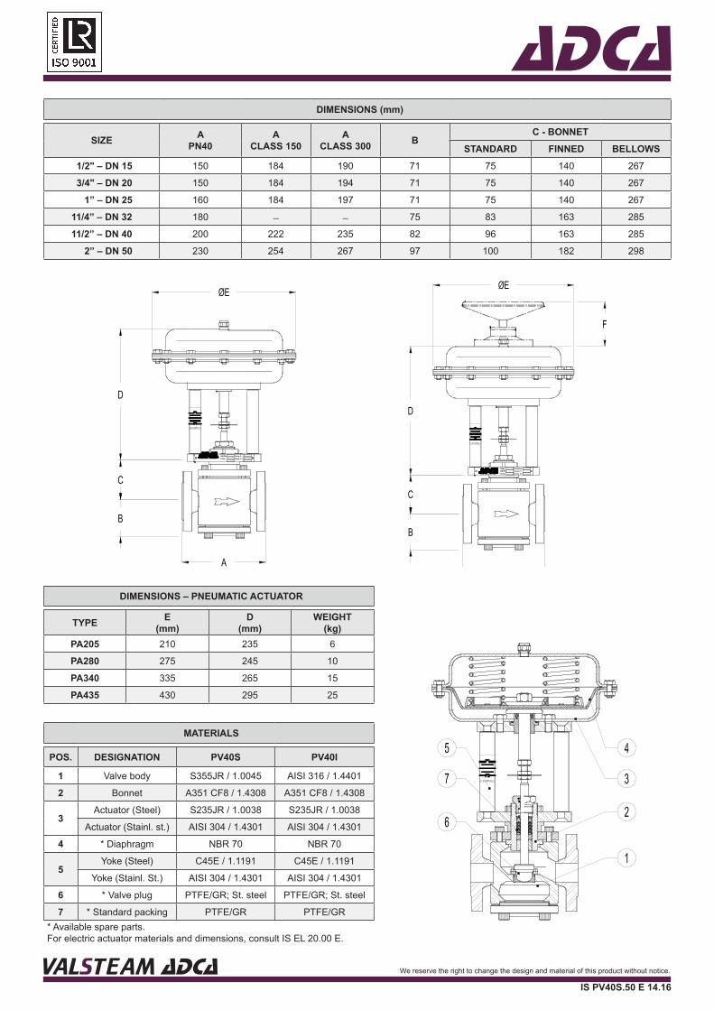
ADCADIMENSIONS (mm)
SIZE APN40
ACLASS 150
ACLASS 300 B
C - BONNETSTANDARD FINNED BELLOWS
1/2" – DN 15 150 184 190 71 75 140 267
3/4" – DN 20 150 184 194 71 75 140 267
1” – DN 25 160 184 197 71 75 140 267
11/4” – DN 32 180 ̶ ̶ 75 83 163 285
11/2” – DN 40 200 222 235 82 96 163 285
2” – DN 50 230 254 267 97 100 182 298
www.valsteam.com
Press.bar
Temp. C°+Temp.C°-
Body
FluidDN/PN
DN/PNFluid
Body
www.valsteam.comTemp.C°-Temp. C°+
Press.bar
MATERIALS
POS. DESIGNATION PV40S PV40I
1 Valve body S355JR / 1.0045 AISI 316 / 1.4401
2 Bonnet A351 CF8 / 1.4308 A351 CF8 / 1.4308
3Actuator (Steel) S235JR / 1.0038 S235JR / 1.0038
Actuator (Stainl. st.) AISI 304 / 1.4301 AISI 304 / 1.4301
4 * Diaphragm NBR 70 NBR 70
5Yoke (Steel) C45E / 1.1191 C45E / 1.1191
Yoke (Stainl. St.) AISI 304 / 1.4301 AISI 304 / 1.4301
6 * Valve plug PTFE/GR; St. steel PTFE/GR; St. steel
7 * Standard packing PTFE/GR PTFE/GR* Available spare parts.For electric actuator materials and dimensions, consult IS EL 20.00 E.
DIMENSIONS – PNEUMATIC ACTUATOR
TYPE E (mm)
D(mm)
WEIGHT(kg)
PA205 210 235 6
PA280 275 245 10
PA340 335 265 15
PA435 430 295 25
VALSTEAM ADCA We reserve the right to change the design and material of this product without notice.
IS PV40S.50 E 14.16
ADCA
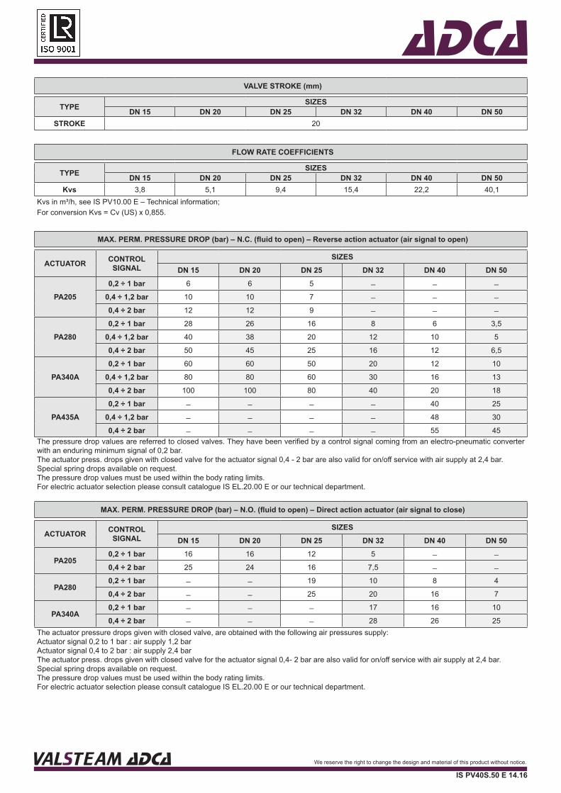
MAX. PERM. PRESSURE DROP (bar) – N.C. (fluid to open) – Reverse action actuator (air signal to open)
ACTUATOR CONTROL SIGNAL
SIZESDN 15 DN 20 DN 25 DN 32 DN 40 DN 50
PA2050,2 ÷ 1 bar 6 6 5 ̶ ̶ ̶
0,4 ÷ 1,2 bar 10 10 7 ̶ ̶ ̶
0,4 ÷ 2 bar 12 12 9 ̶ ̶ ̶
PA2800,2 ÷ 1 bar 28 26 16 8 6 3,5
0,4 ÷ 1,2 bar 40 38 20 12 10 5
0,4 ÷ 2 bar 50 45 25 16 12 6,5
PA340A0,2 ÷ 1 bar 60 60 50 20 12 10
0,4 ÷ 1,2 bar 80 80 60 30 16 13
0,4 ÷ 2 bar 100 100 80 40 20 18
PA435A0,2 ÷ 1 bar ̶ ̶ ̶ ̶ 40 25
0,4 ÷ 1,2 bar ̶ ̶ ̶ ̶ 48 30
0,4 ÷ 2 bar ̶ ̶ ̶ ̶ 55 45The pressure drop values are referred to closed valves. They have been verified by a control signal coming from an electro-pneumatic converter with an enduring minimum signal of 0,2 bar. The actuator press. drops given with closed valve for the actuator signal 0,4 - 2 bar are also valid for on/off service with air supply at 2,4 bar.Special spring drops available on request. The pressure drop values must be used within the body rating limits.For electric actuator selection please consult catalogue IS EL.20.00 E or our technical department.
VALVE STROKE (mm)
TYPE SIZESDN 15 DN 20 DN 25 DN 32 DN 40 DN 50
STROKE 20
FLOW RATE COEFFICIENTS
TYPE SIZESDN 15 DN 20 DN 25 DN 32 DN 40 DN 50
Kvs 3,8 5,1 9,4 15,4 22,2 40,1Kvs in m³/h, see IS PV10.00 E – Technical information;For conversion Kvs = Cv (US) x 0,855.
MAX. PERM. PRESSURE DROP (bar) – N.O. (fluid to open) – Direct action actuator (air signal to close)
ACTUATOR CONTROL SIGNAL
SIZESDN 15 DN 20 DN 25 DN 32 DN 40 DN 50
PA2050,2 ÷ 1 bar 16 16 12 5 ̶ ̶
0,4 ÷ 2 bar 25 24 16 7,5 ̶ ̶
PA2800,2 ÷ 1 bar ̶ ̶ 19 10 8 4
0,4 ÷ 2 bar ̶ ̶ 25 20 16 7
PA340A0,2 ÷ 1 bar ̶ ̶ ̶ 17 16 10
0,4 ÷ 2 bar ̶ ̶ ̶ 28 26 25The actuator pressure drops given with closed valve, are obtained with the following air pressures supply:Actuator signal 0,2 to 1 bar : air supply 1,2 bar Actuator signal 0,4 to 2 bar : air supply 2,4 barThe actuator press. drops given with closed valve for the actuator signal 0,4- 2 bar are also valid for on/off service with air supply at 2,4 bar.Special spring drops available on request. The pressure drop values must be used within the body rating limits.For electric actuator selection please consult catalogue IS EL.20.00 E or our technical department.
VALSTEAM ADCA We reserve the right to change the design and material of this product without notice.
IS PV40S.50 E 14.16
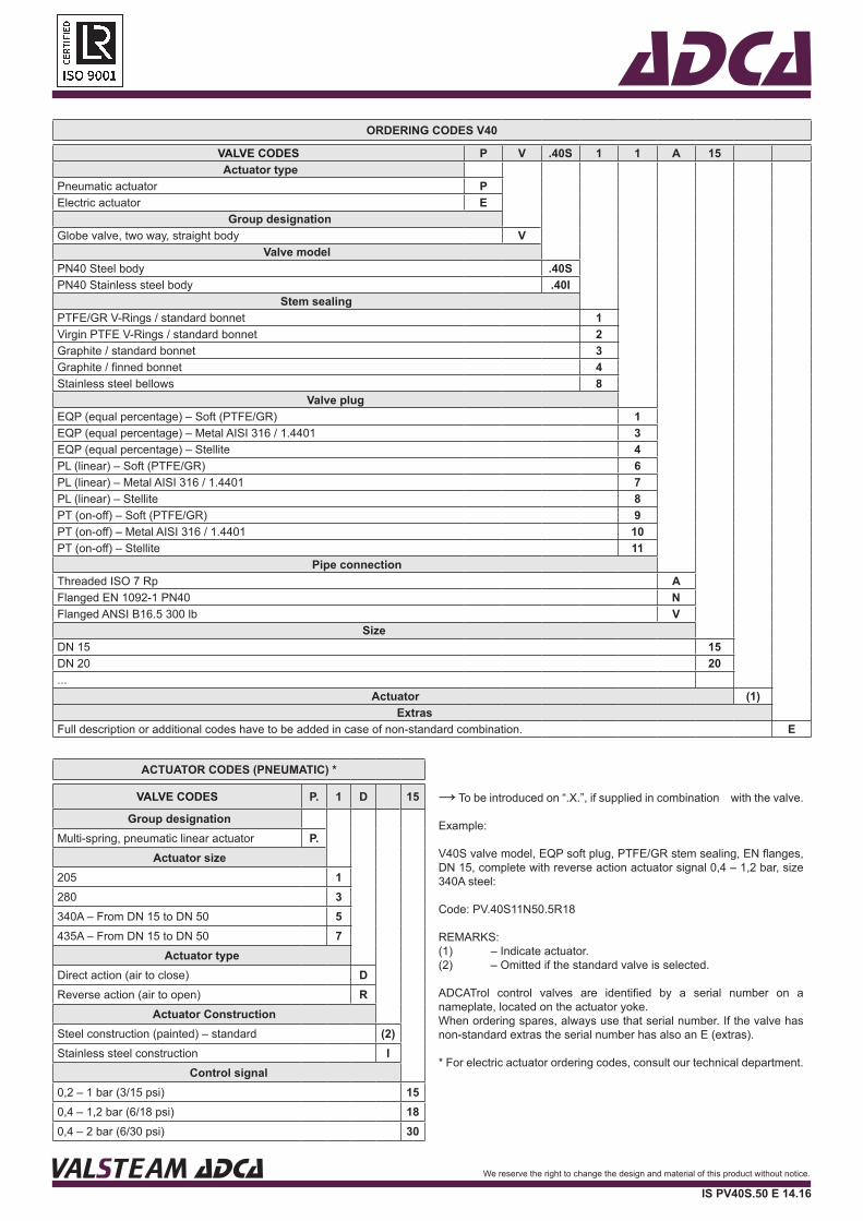
ADCAORDERING CODES V40
VALVE CODES P V .40S 1 1 A 15Actuator type
Pneumatic actuator PElectric actuator E
Group designationGlobe valve, two way, straight body V
Valve modelPN40 Steel body .40SPN40 Stainless steel body .40I
Stem sealingPTFE/GR V-Rings / standard bonnet 1Virgin PTFE V-Rings / standard bonnet 2Graphite / standard bonnet 3Graphite / finned bonnet 4Stainless steel bellows 8
Valve plugEQP (equal percentage) – Soft (PTFE/GR) 1EQP (equal percentage) – Metal AISI 316 / 1.4401 3EQP (equal percentage) – Stellite 4PL (linear) – Soft (PTFE/GR) 6PL (linear) – Metal AISI 316 / 1.4401 7PL (linear) – Stellite 8PT (on-off) – Soft (PTFE/GR) 9PT (on-off) – Metal AISI 316 / 1.4401 10PT (on-off) – Stellite 11
Pipe connectionThreaded ISO 7 Rp AFlanged EN 1092-1 PN40 NFlanged ANSI B16.5 300 lb V
SizeDN 15 15DN 20 20...
Actuator (1)Extras
Full description or additional codes have to be added in case of non-standard combination. E
ACTUATOR CODES (PNEUMATIC) *
VALVE CODES P. 1 D 15
Group designationMulti-spring, pneumatic linear actuator P.
Actuator size205 1280 3340A – From DN 15 to DN 50 5435A – From DN 15 to DN 50 7
Actuator typeDirect action (air to close) DReverse action (air to open) R
Actuator ConstructionSteel construction (painted) – standard (2)Stainless steel construction I
Control signal0,2 – 1 bar (3/15 psi) 150,4 – 1,2 bar (6/18 psi) 180,4 – 2 bar (6/30 psi) 30
→ To be introduced on “.X.”, if supplied in combination with the valve.
Example:
V40S valve model, EQP soft plug, PTFE/GR stem sealing, EN flanges, DN 15, complete with reverse action actuator signal 0,4 – 1,2 bar, size 340A steel:
Code: PV.40S11N50.5R18
REMARKS:(1) – Indicate actuator.(2) – Omitted if the standard valve is selected.
ADCATrol control valves are identified by a serial number on a nameplate, located on the actuator yoke.When ordering spares, always use that serial number. If the valve has non-standard extras the serial number has also an E (extras).
* For electric actuator ordering codes, consult our technical department.
VALSTEAM ADCA We reserve the right to change the design and material of this product without notice.
IS PV40S.50 E 14.16


![TP menu final 3.13.18 - Thai Princess 2018 menu.pdfHot Tea $2.00 Thai Lemon Tea $3.50 Thai Iced Tea $3.50 Thai Iced Coffee $3.50 Coconut Juice $3.50 Mango Juice $3.50 [V] = Vegetarian](https://img.pdfslide.us/doc/110x75/5f3f90a3f934dc1c977475a0/tp-menu-final-31318-thai-2018-menupdf-hot-tea-200-thai-lemon-tea-350-thai.jpg)