Embed Size (px)
Citation preview
Part No. 135545-01Revision D, October 1999
3500/45POSITION MONITOR
OPERATION ANDMAINTENANCE MANUAL

© Bently Nevada Corporation 1999
All Rights Reserved
No part of this publication my be reproduced, transmitted, stored in a retrieval system or translated into anyhuman or computer language, in any form or by any means, electronic, mechanical, magnetic, optical,chemical, manual, or otherwise, without the prior written permission of the copyright owner,
Bently Nevada Corporation1617 Water Street
Minden, Nevada 89423 USATelephone (800) 227-5514 or (775) 782-3611
Fax (775) 782-9259
Copyright infringement is a serious matter underthe United States of America and foreign copyright laws
Keyphasor ® and Proximitor ® are registered trademarks of Bently Nevada Corporation.
3500/45 Operation and Maintenance
iii
Additional Information
3500 Monitoring System Rack Installation and Maintenance Manual (129766-01)
• general description of a standard system
• general description of a Triple Modular redundant (TMR) system
• instructions for installing and removing the module from a 3500 rack
• drawings for all cables used in the 3500 Monitoring System
3500 Monitoring System Rack Configuration and Utilities Guide (129777-01)
• guidelines for using the 3500 Rack Configuration software for setting the operatingparameters of the module
• guidelines for using the 3500 test utilities to verify that the input and output terminals on themodule are operating properly
3500 Monitoring System Computer Hardware and Software Manual (128158-01)
• instructions for connecting the rack to 3500 host computer
• procedures for verifying communication
• procedures for installing software
• guidelines for using Data Acquisition / DDE Server and Operator Display Software
• procedures and diagrams for setting up network and remote communications
3500 Field Wiring Diagram Package (130432-01)
• diagrams that show how to hook up a particular transducer
• lists of recommended wiring
NOTICE:This manual does not contain all the information required to operate andmaintain the Keyphasor Module. Refer to the following manuals for otherrequired information.
3500/45 Operation and Maintenance
iv
Contents
1 Receiving and Handling Instructions ..............................................11.1 Receiving Inspection...........................................................................................11.2 Handling and Storing Considerations..................................................................11.3 Disposal Statement ............................................................................................1
2 General Information ..........................................................................22.1 Triple Modular Redundant (TMR) Description......................................................82.2 Available Data .....................................................................................................9
2.2.1 Statuses................................................................................................92.2.2 Proportional Values.............................................................................11
2.3 LED Descriptions...............................................................................................13
3 Configuration Information ..............................................................143.1 Software Configuration Options.........................................................................14
3.1.1 Position Monitor Configuration Options ...............................................143.1.2 Thrust Position Channel Options.........................................................173.1.3 Differential Expansion Channel Options..............................................233.1.4 Ramp Differential Expansion Channel Pair Options ............................293.1.5 Complementary Input Differential Expansion Channel Pair Options....573.1.6 Case Expansion - Paired Options .......................................................643.1.7 Case Expansion - Single Options........................................................723.1.8 Valve Position Options ........................................................................80
3.2 Setpoints ...........................................................................................................913.3 Software Switches .............................................................................................94
4 I/O Module Descriptions .................................................................984.1 Setting the I/O Jumper.......................................................................................994.2 Position I/O Modules (Internal Termination).....................................................100
4.2.1 Position I/O Module for use with Proximitors or DC LVDTs...............1004.2.2 Position I/O Module for use with AC LVDTs......................................1014.2.3 Position I/O Module for use with Rotary Potentiometer Transducers.1024.2.4 Wiring Euro Style Connectors ...........................................................103
4.3 Position I/O Modules (External Termination) ...................................................1044.3.1 Position I/O Modules .........................................................................1044.3.2 Position I/O Module (TMR Discrete)..................................................1074.3.3 Position I/O Module (TMR Bussed ) ..................................................1084.3.4 External Termination Blocks..............................................................1094.3.5 Cable Pin Outs..................................................................................120
5 Maintenance ..................................................................................1225.1 Verifying a 3500 Rack - Position Monitor Module ............................................122
5.1.1 Choosing a Maintenance Interval ......................................................1235.1.2 Required Test Equipment .................................................................1235.1.3 Typical Verification Test Setup..........................................................1245.1.4 Using the Rack Configuration Software ............................................1265.1.5 Thrust Position and Differential Expansion Channels........................129
3500/45 Operation and Maintenance
v
5.1.6 Ramp Differential Expansion Channels.............................................1405.1.7 Complementary Input Differential Expansion Channels ....................1565.1.8 Case Expansion Channels................................................................1665.1.9 Valve Position Channels ...................................................................1815.1.10 Verify Recorder Outputs .................................................................1955.1.11 If a Channel Fails a Verification Test ..............................................196
5.2 Adjusting the Scale Factor, Sensitivity, Zero Position, and Cross Over Voltage.........................................................................................196
5.2.1 Adjusting the Scale Factor or Channel Sensitivity.............................1985.2.2 Zero Position Adjustment Description for Thrust Position and Differential Expansion.......................................................................1995.2.3 Zero Position Adjustment Description for Ramp Differential Expansion.........................................................................................2015.2.4 Adjusting the Zero Position ...............................................................2045.2.5 Direct Autozero Function Description................................................2055.2.6 Procedure for Direct Autozero ..........................................................2055.2.7 Cross Over Voltage Adjustment Description .....................................2075.2.8 Adjusting the Cross Over Voltage for Complementary Input Differential Expansion.......................................................................208
5.3 Adjusting the Upscale and Downscale Voltage for Case Expansion................2095.4 Adjusting the Upscale and Downscale Voltage for Valve Position ...................2115.5 Performing Firmware Upgrades ......................................................................212
5.5.1 Installation Procedure .......................................................................212
6 Troubleshooting ............................................................................2166.1 Self-test...........................................................................................................2166.2 LED Fault Conditions ......................................................................................2176.3 System Event List Messages ..........................................................................2186.4 Alarm Event List Messages.............................................................................233
7 Ordering Information.....................................................................234
8 Specifications ................................................................................237

3500/45 Operation and Maintenance
vi
3500/45 Operation and Maintenance 1 Receiving and Handling Instructions
1
1 Receiving and Handling Instructions
1.1 Receiving InspectionVisually inspect the module for obvious shipping damage. If shipping damage isapparent, file a claim with the carrier and submit a copy to Bently Nevada Corporation.
1.2 Handling and Storing ConsiderationsCircuit boards contain devices that are susceptible to damage when exposed toelectrostatic charges. Damage caused by obvious mishandling of the board will voidthe warranty. To avoid damage, observe the following precautions in the order given.
Application Alert
Machinery protectionmay be lost when thismodule is removedfrom the rack.
• Do not discharge static electricity onto the circuit board. Avoid tools or proceduresthat would subject the circuit board to static damage. Some possible causesinclude ungrounded soldering irons, nonconductive plastics, and similar materials.
• Personnel must be grounded with a suitable grounding strap (such as 3M VelostatNo. 2060) before handling or maintaining a printed circuit board.
• Transport and store circuit boards in electrically conductive bags or foil.
• Use extra caution during dry weather. Relative humidity less than 30% tends tomultiply the accumulation of static charges on any surface.
• When performed properly, this module may be installed into or removed from therack while power is applied to the rack. Refer to the Rack Installation andMaintenance Manual (part number 129766-01) for the proper procedure.
1.3 Disposal StatementCustomer and third parties that are in control of product at the end of its life or at theend of its use are solely responsible for proper disposal of product. No person, firm,corporation, association or agency that is in control of product shall dispose of it in amanner that is in violation of United States state laws, United States federal laws, orany applicable international law. Bently Nevada Corporation is not responsible fordisposal of product at the end of its life or at the end of its use.
2 General Information 3500/45 Operation and Maintenance
2
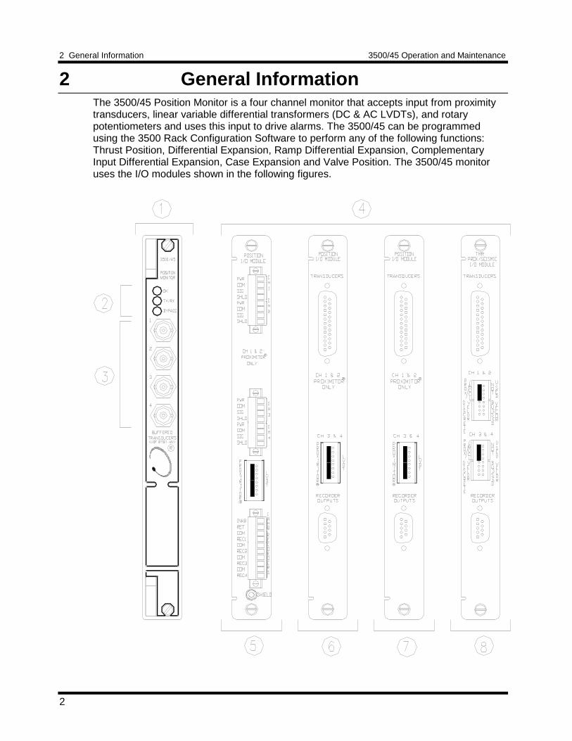
2 General InformationThe 3500/45 Position Monitor is a four channel monitor that accepts input from proximitytransducers, linear variable differential transformers (DC & AC LVDTs), and rotarypotentiometers and uses this input to drive alarms. The 3500/45 can be programmedusing the 3500 Rack Configuration Software to perform any of the following functions:Thrust Position, Differential Expansion, Ramp Differential Expansion, ComplementaryInput Differential Expansion, Case Expansion and Valve Position. The 3500/45 monitoruses the I/O modules shown in the following figures.
3500/45 Operation and Maintenance 2 General Information
3
1) Front view of monitor.2) Status LEDs, refer to Section 2.3 (LED Descriptions).3) Buffered Transducer Outputs: Provide an unfiltered output for each of the four
transducers. Channels 3 and 4 are level shifted by –10V when using DC LVDTs.When using AC LVDTs the buffered output is a DC output derived fromconditioning of the two AC inputs from the transducer’s secondary outputs. All areshort circuit protected.
4) Rear views of the various I/O modules used with Proximitors or DC LVDTs.5) Position I/O Module, Internal Termination, for use with Proximitors or DC LVDTs.6) Position I/O Module, External Termination, for use with Proximitors or DC LVDTs.7) Position I/O Module, TMR Discrete, External Termination, for use with Proximitors
or DC LVDTs.8) Prox/Seismic I/O Module, TMR Bussed, External Termination for use with Proxes.
2 General Information 3500/45 Operation and Maintenance
4
3500/45 Operation and Maintenance 2 General Information
5
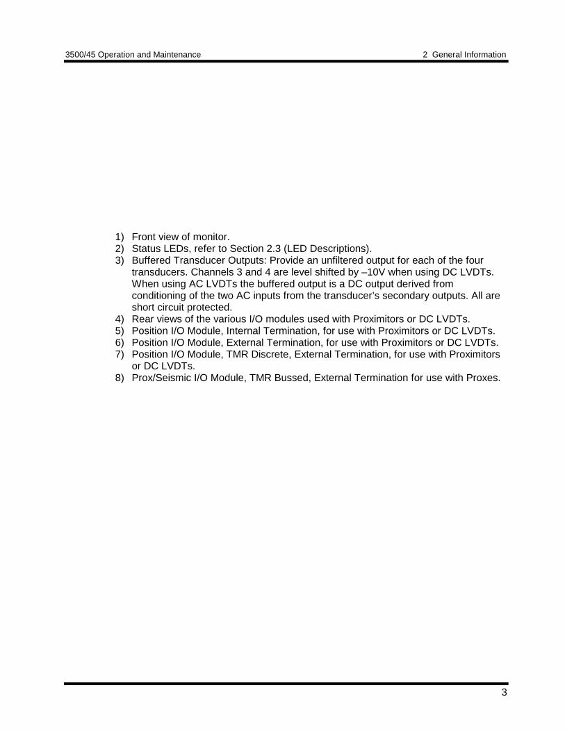
9) Rear views of the various I/O modules used with AC LVDTs.10) Position I/O Module, Internal Termination, for use with AC LVDTs.11) Position I/O Module, External Termination, for use with AC LVDTs.12) Rear views of the various I/O modules used with Rotary Potentiometers.13) Position I/O Module, Internal Termination, for use with Rotary Potentiometers.14) Position I/O Module, External Termination, for use with Rotary Potentiometers.
2 General Information 3500/45 Operation and Maintenance
6
Section 4 (I/O Module Descriptions) contains detailed information about the I/Omodules. The modules can receive input from the following transducers:
Proximitor Transducers DC LVDT Transducers7200 5, 8, 11, and 14 mm3300 8 mm3300XL 8 mm25, 35, and 50 mm Extended Range50 mm DERAM3000
135613 High Temp LVDT - 25, 50, and 100mm24765 LVDT - 25, 50, and 100 mm
Rotary Transducers AC LVDT Transducers
300 deg Rotary Potentiometer1” (25.4 mm) range2” (50.8 mm) range4” (101.6 mm) range6” (152.4 mm) range8” (203.2 mm) range10” (254 mm) range12” (304.8 mm) range20” (508 mm) range
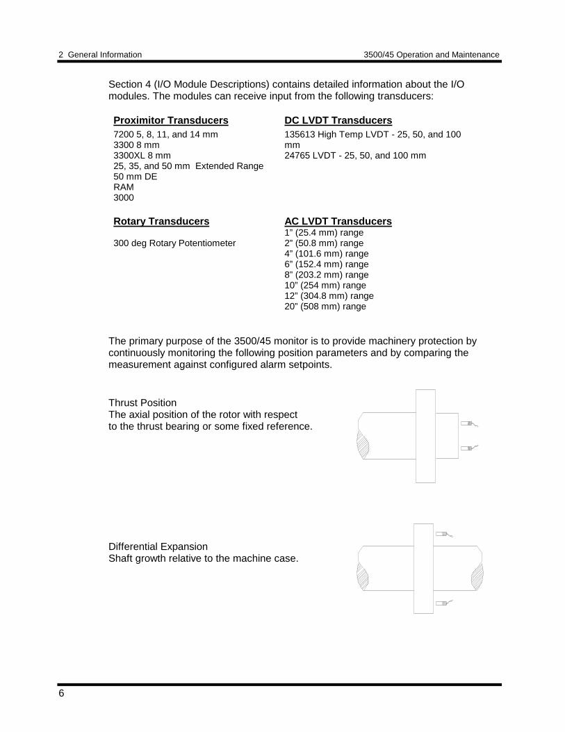
The primary purpose of the 3500/45 monitor is to provide machinery protection bycontinuously monitoring the following position parameters and by comparing themeasurement against configured alarm setpoints.
Thrust PositionThe axial position of the rotor with respectto the thrust bearing or some fixed reference.
Differential ExpansionShaft growth relative to the machine case.
3500/45 Operation and Maintenance 2 General Information
7
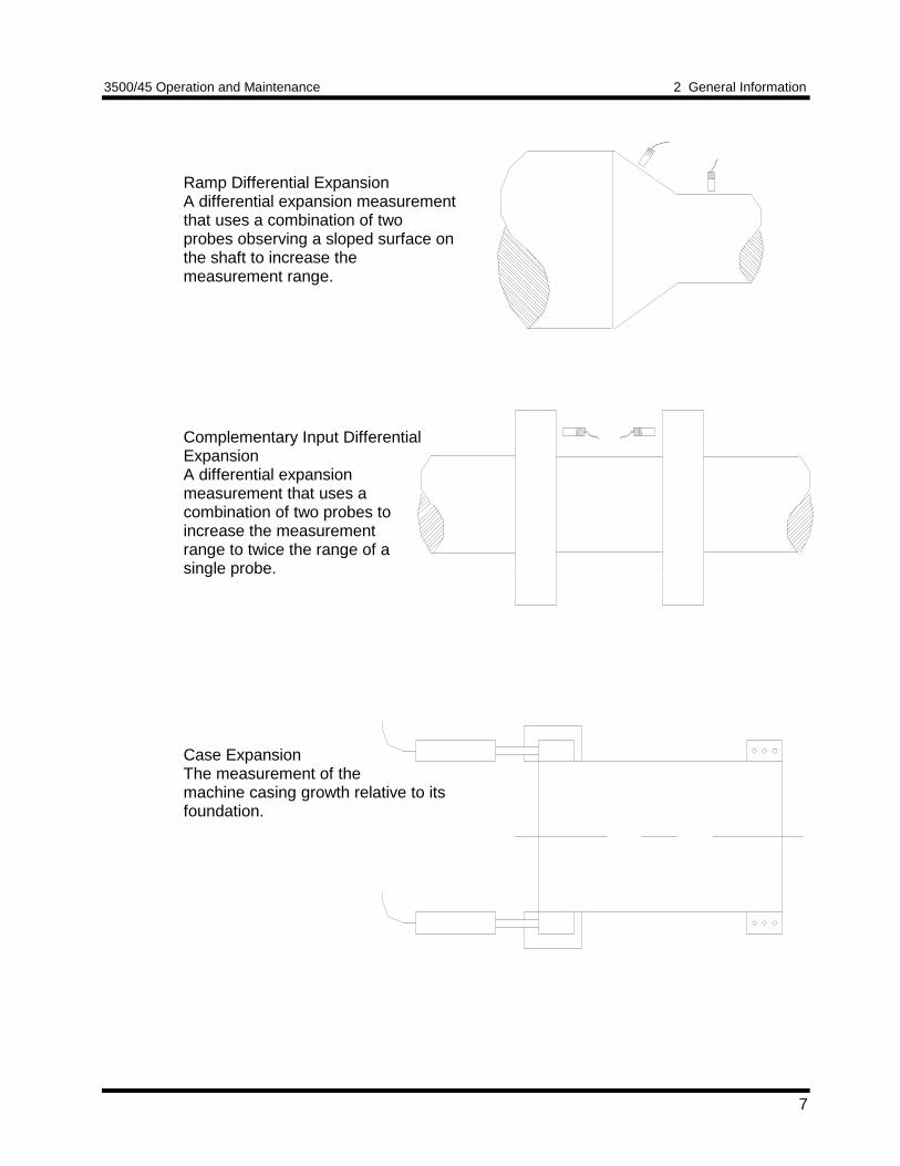
Ramp Differential ExpansionA differential expansion measurementthat uses a combination of twoprobes observing a sloped surface onthe shaft to increase themeasurement range.
Complementary Input DifferentialExpansionA differential expansionmeasurement that uses acombination of two probes toincrease the measurementrange to twice the range of asingle probe.
Case ExpansionThe measurement of themachine casing growth relative to itsfoundation.
2 General Information 3500/45 Operation and Maintenance
8
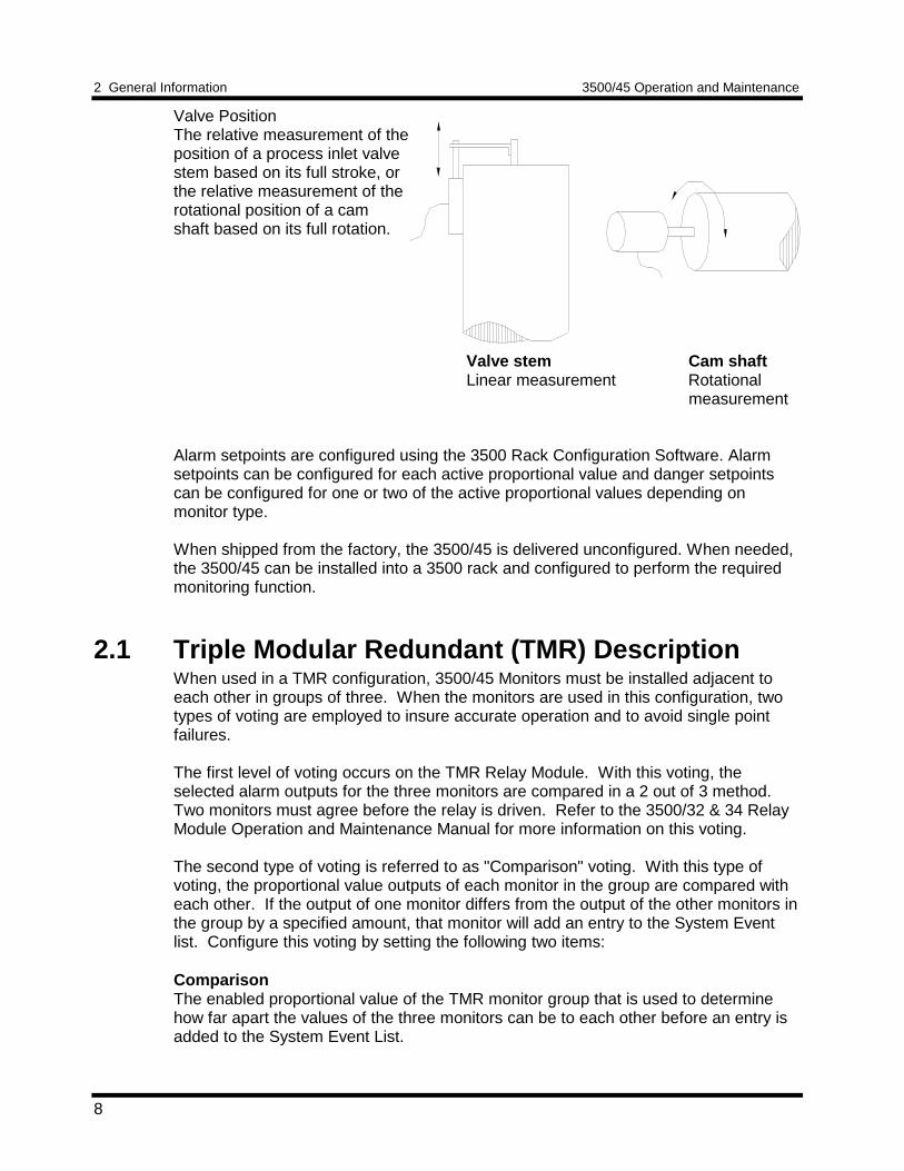
Valve PositionThe relative measurement of theposition of a process inlet valvestem based on its full stroke, orthe relative measurement of therotational position of a camshaft based on its full rotation.
Valve stem Cam shaftLinear measurement Rotational
measurement
Alarm setpoints are configured using the 3500 Rack Configuration Software. Alarmsetpoints can be configured for each active proportional value and danger setpointscan be configured for one or two of the active proportional values depending onmonitor type.
When shipped from the factory, the 3500/45 is delivered unconfigured. When needed,the 3500/45 can be installed into a 3500 rack and configured to perform the requiredmonitoring function.
2.1 Triple Modular Redundant (TMR) DescriptionWhen used in a TMR configuration, 3500/45 Monitors must be installed adjacent toeach other in groups of three. When the monitors are used in this configuration, twotypes of voting are employed to insure accurate operation and to avoid single pointfailures.
The first level of voting occurs on the TMR Relay Module. With this voting, theselected alarm outputs for the three monitors are compared in a 2 out of 3 method.Two monitors must agree before the relay is driven. Refer to the 3500/32 & 34 RelayModule Operation and Maintenance Manual for more information on this voting.
The second type of voting is referred to as "Comparison" voting. With this type ofvoting, the proportional value outputs of each monitor in the group are compared witheach other. If the output of one monitor differs from the output of the other monitors inthe group by a specified amount, that monitor will add an entry to the System Eventlist. Configure this voting by setting the following two items:
ComparisonThe enabled proportional value of the TMR monitor group that is used to determinehow far apart the values of the three monitors can be to each other before an entry isadded to the System Event List.
3500/45 Operation and Maintenance 2 General Information
9
% ComparisonThe highest allowed percent difference between the middle value of the three monitorsin a TMR group and the individual values of each monitor.
For TMR applications, two types of input configurations are available: bussed I/O ordiscrete I/O. Bussed I/O uses the signal from a single non-redundant transducer andprovides that signal to all modules in the TMR group through a single 3500 BussedExternal Termination Block (bussed TMR is not available with Case Expansion or withValve Position).
Discrete I/O requires three redundant transducers at each measurement location onthe machine. The input from each transducer is connected to separate 3500 ExternalTermination Blocks. (Discrete TMR is not available with Valve Position.)
2.2 Available DataThe Position Monitor returns specific proportional values dependent upon the type ofchannel configured. The monitor also returns both monitor and channel statuseswhich are common to all types of channels.
2.2.1 StatusesThe following statuses are provided by the Position Monitor. This section describesthe available statuses and where they can be found.
Monitor StatusOKThis indicates if the monitor is functioning correctly. A not OK status is returnedunder any of the following conditions:• Hardware Failure in the module• Node Voltage Failure• Transducer System Failure• Configuration Failure• Slot ID Failure
If the Monitor OK status goes not OK, then the system OK Relay on the RackInterface I/O Module (RIM) will be driven not OK.
Alert/Alarm 1This indicates whether the monitor has entered Alert/Alarm 1. A monitor will enterthe Alert/Alarm 1 state when any proportional value provided by the monitorexceeds its configured Alert/Alarm 1 setpoint.
Danger/Alarm 2This indicates whether the monitor has entered Danger/Alarm 2. A monitor willenter the Danger/Alarm 2 state when any proportional value provided by themonitor exceeds its configured Danger/Alarm 2 setpoint.
2 General Information 3500/45 Operation and Maintenance
10
BypassThis indicates when the monitor has bypassed alarming on one or moreproportional values at a channel. When a channel bypass status is set, thismonitor bypass status will also be set.
Configuration FaultThis indicates if the monitor configuration is valid
Special Alarm InhibitThis indicates whether all the non-primary Alert/Alarm 1 alarms in the monitor areinhibited. This status is active when:• The Alarm Inhibit contact on the I/O Module is closed (active).• A software Special Channel Alarm Inhibit is active.
Channel StatusOKThis indicates that no fault has been detected by the associated monitor channel.
Alert/Alarm 1This indicates whether the associated monitor channel has entered Alert/Alarm 1.A channel will enter the Alert/Alarm 1 state when any proportional value providedby the channel exceeds its configured Alert/Alarm 1 setpoint.
Danger/Alarm 2This indicates whether the associated monitor channel has entered Danger/Alarm2. A channel will enter the Danger/Alarm 2 state when any proportional valueprovided by the channel exceeds its configured Danger/Alarm 2 setpoint.
BypassThis indicates when the associated monitor channel has bypassed one or moreproportional values of the channel. A Bypass status may result when:• A transducer is not OK or the channel is in Timed OK Channel Defeat.• The monitor has detected a serious internal fault.
Special Alarm InhibitThis indicates whether all the nonprimary Alert/Alarm 1 alarms in the associatedmonitor channel are inhibited. This status is active when:• The Alarm Inhibit contact on the monitor I/O module is closed (active).• A software Special Channel Alarm Inhibit is active.
OffThis indicates whether the channel has been turned off. Turn the monitorchannels off (inactivated) using the Rack Configuration Software.

3500/45 Operation and Maintenance 2 General Information
11
The following table shows where the statuses can be found.
Statuses CommunicationGatewayModule
RackConfiguration
Software
OperatorDisplay
Software
Monitor OK X X
Monitor Alert/Alarm 1 X X
Monitor Danger/Alarm 2 X X
Monitor Bypass X
Monitor Configuration Fault X
Monitor Special Alarm Inhibit X
Channel OK X X X
Channel Alert/Alarm 1 X X X
Channel Danger/Alarm 2 X X X
Channel Bypass X X X
Channel Special Alarm Inhibit X X X
Channel Off X X
2.2.2 Proportional ValuesProportional values are vibration or position measurements used to monitor themachine. The proportional values returned by the Position Monitor are described below:
Thrust Position and Differential Expansion
*Direct: The physical distance between the face of the proximity probe tip and theobserved surface. Direct is displayed in units of mils, micrometres,millimetres, or inches.
Gap: The physical distance between the face of the proximity probe tip and theobserved surface. Gap is measured in volt units.
Ramp Differential Expansion
Composite: The axial position of the rotor relative to two proximity probes aftercompensation for the effect of rotor radial movement. Composite iscalculated by the monitor using the Direct proportional value of the twoindividual proximity probe channels. Composite is returned on bothchannels of the channel pair in units of millimetres or inches.
2 General Information 3500/45 Operation and Maintenance
12
Direct: The axial position of the rotor relative to only one proximity probe. TheDirect proportional value is not compensated for the effect of rotor radialmovement. On the "flat" channel of a Standard Single Ramp DifferentialExpansion channel pair the Direct value is actually radial movementtranslated into an apparent axial position measurement.
Gap: The physical distance between the face of the proximity probe tip andthe observed surface. Gap is measured in volt units.
Complementary Input Differential Expansion
*Composite: The overall axial position of the rotor measured using two proximityprobes mounted in a "complementary" fashion so that the overallmeasurement range is twice the range of a single proximity probe.Composite is calculated by the monitor using the Direct proportionalvalue from each of the two proximity probes. Composite is returned onboth channels of the channel pair.
Direct: The axial position of the rotor relative to only one proximity probe. Therange of the Direct proportional value is one half of the range of theComposite.
Gap: The physical distance between the face of the proximity probe tip andthe observed surface. Gap is measured in volt units.
Case Expansion
Composite: The difference between the two measured Direct values when LVDTsare mounted on both sides of the machine case. Composite is returnedon both channels of the channel pair in units of millimeters or inches.
*Direct: The position of the machine case relative to the LVDT. Direct isdisplayed in units of millimeters or inches.
Position: The position of the LVDT core relative to the LVDT. Position ismeasured in units of volts.
Valve Position
*Direct: The position of the of the valve stem relative to the AC LVDT or theposition of the cam shaft relative to the rotary position transducer.Direct is displayed in units of % open or % closed.
Position: The position of the AC LVDT core relative to the AC LVDT or theposition of the rotary transducer shaft relative to the rotary transducer.Position is measured in units of volts.
* This is the primary value for each channel type. You can place these values intocontiguous registers on the Communications Gateway Module.
3500/45 Operation and Maintenance 2 General Information
13
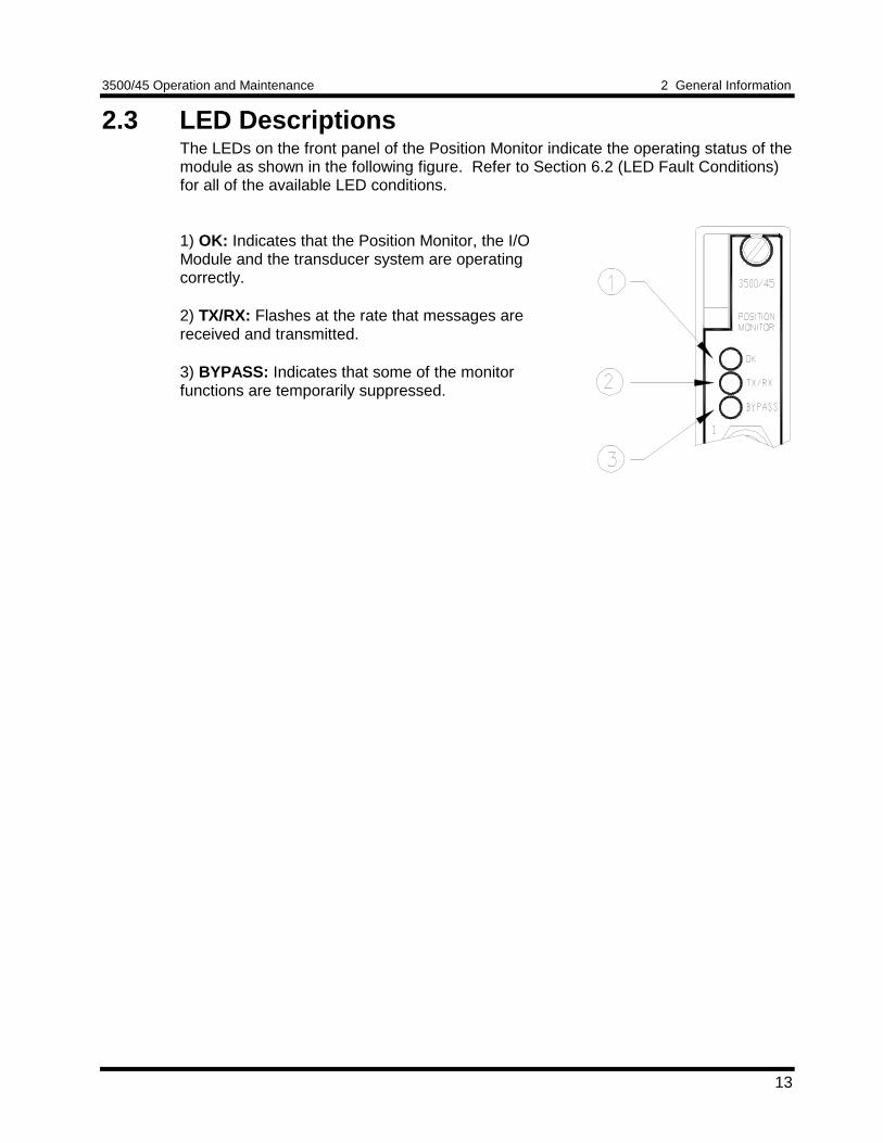
2.3 LED DescriptionsThe LEDs on the front panel of the Position Monitor indicate the operating status of themodule as shown in the following figure. Refer to Section 6.2 (LED Fault Conditions)for all of the available LED conditions.
1) OK: Indicates that the Position Monitor, the I/OModule and the transducer system are operatingcorrectly.
2) TX/RX: Flashes at the rate that messages arereceived and transmitted.
3) BYPASS: Indicates that some of the monitorfunctions are temporarily suppressed.
3 Configuration Information 3500/45 Operation and Maintenance
14
3 Configuration InformationThe 3500/45 Position Monitor cannot operate without a valid configuration.Configuration is the process of defining the transducers and I/O modules that areconnected to the monitor and then setting operation parameters for all channels in themonitor. Use this section to gather the information that you will need to configure a3500/45 monitor and then use the 3500 Rack Configuration Program to download theconfiguration to the monitor.
The 3500/45 configuration parameters are organized into software configurationoptions (section 3.1), alarm setpoints (section 3.2), and software switches (section3.3).
3.1 Software Configuration OptionsThis section lists the configuration options and restrictions for the 3500/45 monitor andthen for each channel type.
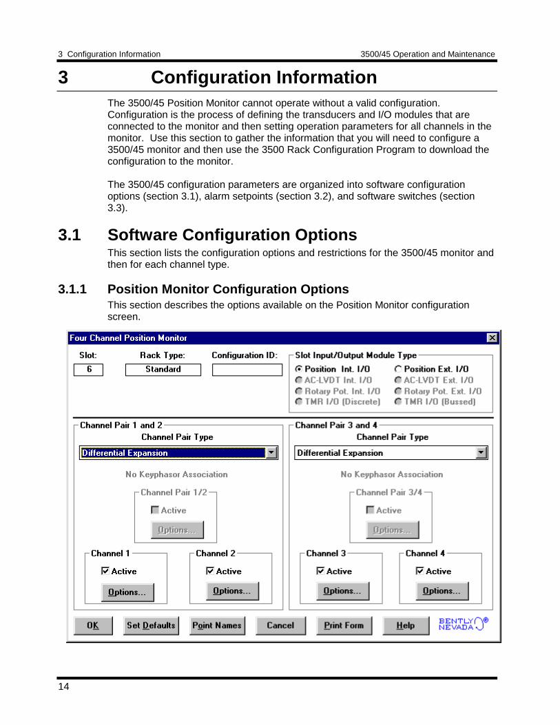
3.1.1 Position Monitor Configuration OptionsThis section describes the options available on the Position Monitor configurationscreen.
3500/45 Operation and Maintenance 3 Configuration Information
15
Reference InformationThese fields contain information that indicates which module you are configuring.
SlotThe location of the Position Monitor in the 3500 rack (2 through 15).
Rack TypeIdentifies the type of Rack Interface Module installed in the rack (Standard orTMR).
Configuration IDContains a unique six character identifier which is entered when a configuration isdownloaded to the 3500 rack.
Slot Input/Output Module TypeThe I/O field lets you identify the type of I/O module that is attached to the PositionMonitor. (The option selected must agree with the I/O module installed.)
Internal I/OUsed when each monitor has its own I/O module and the application does not requireTriple Modular Redundancy. The transducer field wiring is connected directly to the I/OModule. There are three types of internal I/O modules:
1. Position Int. I/O: used to interface to Proximitors or DC LVDTs2. AC LVDT Int. I/O: used to interface to AC LVDTs3. Rotary Pot Int. I/O: used to interface to rotary potentiometers
External I/OUsed when each monitor has its own I/O module and the application does not requireTriple Modular Redundancy. The transducer field wiring is connected to an ExternalTermination Block and then routed from the External Termination Block to the I/OModule through a 25-pin cable. The recorder field wiring is connected to an ExternalTermination Block and then routed from the External Termination Block to the PositionI/O Module through a 9-pin cable. There are three types of external I/O modules:
1. Position Ext. I/O: used to interface to Proximitors or DC LVDTs2. AC LVDT Ext. I/O: used to interface to AC LVDTs3. Rotary Pot Ext. I/O: used to interface to rotary potentiometers
TMR I/OUsed when the monitoring application requires redundancy of either the monitor or themonitor and the sensor. Two types of TMR I/O systems are available:
TMR I/O (Discrete)Use this I/O system when triple redundant monitors and triple redundant sensorsare required. A set of twelve transducers provide input to three identical monitors inadjacent rack slots. The field wiring for the three transducers connects to threeindividual standard External Termination Blocks and is connected to three PositionI/O Modules by 25-pin cables. The connection between the External TerminationBlocks and the rack is made with a 25-pin cable. The recorder field wiring isconnected to a Recorder External Termination Block and then connected to thePosition I/O Modules by a 9-pin cable.
3 Configuration Information 3500/45 Operation and Maintenance
16
TMR I/O (Bussed)Use this I/O system when triple redundant monitors receive input from a singlesensor. This option is only available when used with Proximity transducers. Fourtransducers are connected to three identical monitors in adjacent rack slots. Thetransducer field wiring is connected to a Bussed External Termination Block andthen is connected to three Proximitor/Seismic TMR I/O Modules through three 24-pin cables. The recorder field wiring is connected to a Recorder ExternalTermination Block and then connected to the Proximitor/Seismic TMR I/OModules by a 9-pin cable.
Channel Pair 1 and 2Channel Pair 3 and 4The fields within these boxes pertain to both channels of the channel pair.
Channel Pair TypeThe type of monitoring which is to be performed by the channel pair. The followingchannel pair types are available in the Position Monitor:
Thrust PositionDifferential Expansion*Standard Single Ramp Differential Expansion*Non-standard Single Ramp Differential Expansion*Dual Ramp Differential Expansion**Complementary Input Differential Expansion (CIDE)***Case Expansion - Paired***Case Expansion – SingleValve Position
*These three channel pair types are subsets of a more general monitor type whichis Ramp Differential Expansion. Ramp Differential Expansion is sometimes used inthis manual to refer to all three as a group. Ramp Differential Expansion monitoringuses both channels of the channel pair to make a single composite differentialexpansion measurement.
** Complementary Input Differential Expansion, or CIDE, uses both channels of thechannel pair to make a single composite differential expansion measurement.
*** Case Expansion options are only available on Channel Pair 3 and 4.
Keyphasor® AssociationNo Keyphasor is associated with any of the 3500/45 channel types.
ActiveSelect whether the functions of the channel or channel pair will be turned on () oroff (). Active "on" () is initially selected for the individual channels if the monitortype is Thrust, Differential Expansion, Case Expansion – Single, or Valve Position.If the monitor type is Ramp Differential Expansion, Complementary InputDifferential Expansion or Case Expansion - Paired then Active "on" () is initiallyselected for the channel pair.
3500/45 Operation and Maintenance 3 Configuration Information
17
OptionsA button to display the configuration options for the selected channel or channelpair. Channel pairs are configured together for Ramp Differential Expansion,Complementary Input Differential Expansion, and Case Expansion - Pairedchannel pair types.
3.1.2 Thrust Position Channel OptionsThis section discusses the Configuration Considerations and the Rack ConfigurationSoftware screens associated with the Thrust Position Channel.
3.1.2.1 Thrust Position Channel Configuration ConsiderationsConsider the following items before configuring a Thrust Position Channel:• The "No Keyphasor" option is automatically selected for this channel type. No
Keyphasors are required.• The Thrust Direct full-scale range is dependent upon the transducer type.• The Zero Position voltage range is dependent upon the direct full-scale range, the
selected upscale direction, and the transducer type.• Monitors must be configured in channel pairs (for example, Channels 1 and 2 may
be configured as Thrust Position and Channels 3 and 4 may be configured asDifferential Expansion. However in both cases options such as full-scale range, ortransducer type can be independently configured on each channel ).
• When a full-scale range is modified, the setpoints associated with this proportionalvalue should be readjusted.
3 Configuration Information 3500/45 Operation and Maintenance
18
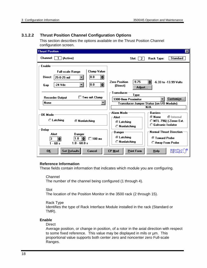
3.1.2.2 Thrust Position Channel Configuration OptionsThis section describes the options available on the Thrust Position Channelconfiguration screen.
Reference InformationThese fields contain information that indicates which module you are configuring.
ChannelThe number of the channel being configured (1 through 4).
SlotThe location of the Position Monitor in the 3500 rack (2 through 15).
Rack TypeIdentifies the type of Rack Interface Module installed in the rack (Standard orTMR).
EnableDirectAverage position, or change in position, of a rotor in the axial direction with respectto some fixed reference. This value may be displayed in mils or µm. Thisproportional value supports both center zero and noncenter zero Full-scaleRanges.
3500/45 Operation and Maintenance 3 Configuration Information
19
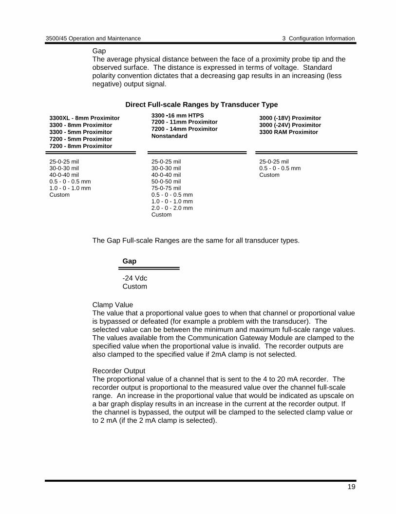
GapThe average physical distance between the face of a proximity probe tip and theobserved surface. The distance is expressed in terms of voltage. Standardpolarity convention dictates that a decreasing gap results in an increasing (lessnegative) output signal.
Direct Full-scale Ranges by Transducer Type
3300XL - 8mm Proximitor3300 - 8mm Proximitor3300 - 5mm Proximitor7200 - 5mm Proximitor7200 - 8mm Proximitor
3300 16 mm HTPS7200 - 11mm Proximitor7200 - 14mm ProximitorNonstandard
3000 (-18V) Proximitor3000 (-24V) Proximitor3300 RAM Proximitor
25-0-25 mil30-0-30 mil40-0-40 mil0.5 - 0 - 0.5 mm1.0 - 0 - 1.0 mmCustom
25-0-25 mil30-0-30 mil40-0-40 mil50-0-50 mil75-0-75 mil0.5 - 0 - 0.5 mm1.0 - 0 - 1.0 mm2.0 - 0 - 2.0 mmCustom
25-0-25 mil0.5 - 0 - 0.5 mmCustom
The Gap Full-scale Ranges are the same for all transducer types.
Gap
-24 VdcCustom
Clamp ValueThe value that a proportional value goes to when that channel or proportional valueis bypassed or defeated (for example a problem with the transducer). Theselected value can be between the minimum and maximum full-scale range values.The values available from the Communication Gateway Module are clamped to thespecified value when the proportional value is invalid. The recorder outputs arealso clamped to the specified value if 2mA clamp is not selected.
Recorder OutputThe proportional value of a channel that is sent to the 4 to 20 mA recorder. Therecorder output is proportional to the measured value over the channel full-scalerange. An increase in the proportional value that would be indicated as upscale ona bar graph display results in an increase in the current at the recorder output. Ifthe channel is bypassed, the output will be clamped to the selected clamp value orto 2 mA (if the 2 mA clamp is selected).
3 Configuration Information 3500/45 Operation and Maintenance
20
OK ModeLatchingIf a channel is configured for Latching OK, once the channel has gone not OK thestatus stays not OK until the channel is in an OK condition and the reset is issued.Reset a latched not OK by using one of the following methods:• the reset switch on the front of the Rack Interface Module• the external contact closure on the Rack Interface I/O Module• the Reset button in the Operator Display Software• the reset command through the Communication Gateway Module
NonlatchingThe OK status of that channel will track the defined OK status of the transducer.
DelayThe time which a proportional value must remain at or above an over alarm level orbelow an under alarm level before an alarm is declared as active.
AlertFirst level alarm that occurs when the proportional value exceeds the selectedAlert/Alarm 1 setpoint. This setpoint can be set on the Setpoint screen. The Alerttime delay is always set at one second intervals (from 1 to 60) for all availableproportional values.
DangerSecond level alarm that occurs when the proportional value exceeds the selectedDanger/Alarm 2 setpoint. This setpoint can be set on the Setpoint screen.
100 ms optionThe 100 ms (typical) option applies to the Danger time delay only and has thefollowing results:
If the 100 ms option is off ():• The Danger time delay can be set at one second intervals (from 1
through 60).• The Danger time delay can be set for all available proportional values.
If the 100 ms option is on ():• The Danger time delay is set to 100 ms.• The Danger time delay can only be set for the primary proportional
value.
Zero Position (Direct)Represents the transducer DC voltage corresponding to the zero indication on thechannel's meter scale for the direct proportional value. The amount of adjustmentallowed is dependent upon the Direct Full-scale Range and the transducer OK limits.To ensure maximum amount of zero adjustment, gap the probe as close as possible tothe zero position voltage automatically displayed in the direct zero position voltagefield.
3500/45 Operation and Maintenance 3 Configuration Information
21
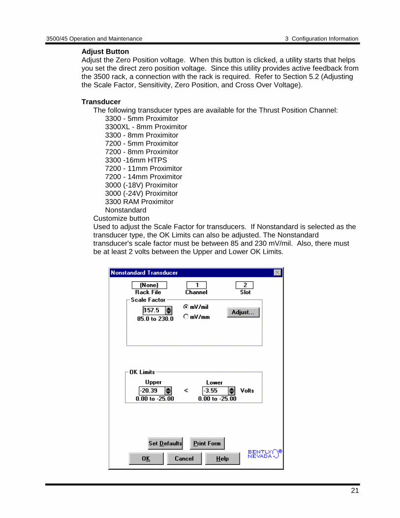
Adjust ButtonAdjust the Zero Position voltage. When this button is clicked, a utility starts that helpsyou set the direct zero position voltage. Since this utility provides active feedback fromthe 3500 rack, a connection with the rack is required. Refer to Section 5.2 (Adjustingthe Scale Factor, Sensitivity, Zero Position, and Cross Over Voltage).
TransducerThe following transducer types are available for the Thrust Position Channel:
3300 - 5mm Proximitor3300XL - 8mm Proximitor3300 - 8mm Proximitor7200 - 5mm Proximitor7200 - 8mm Proximitor3300 -16mm HTPS7200 - 11mm Proximitor7200 - 14mm Proximitor3000 (-18V) Proximitor3000 (-24V) Proximitor3300 RAM ProximitorNonstandard
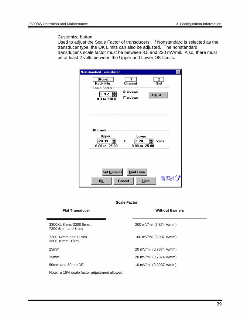
Customize buttonUsed to adjust the Scale Factor for transducers. If Nonstandard is selected as thetransducer type, the OK Limits can also be adjusted. The Nonstandardtransducer's scale factor must be between 85 and 230 mV/mil. Also, there mustbe at least 2 volts between the Upper and Lower OK Limits.
3 Configuration Information 3500/45 Operation and Maintenance
22
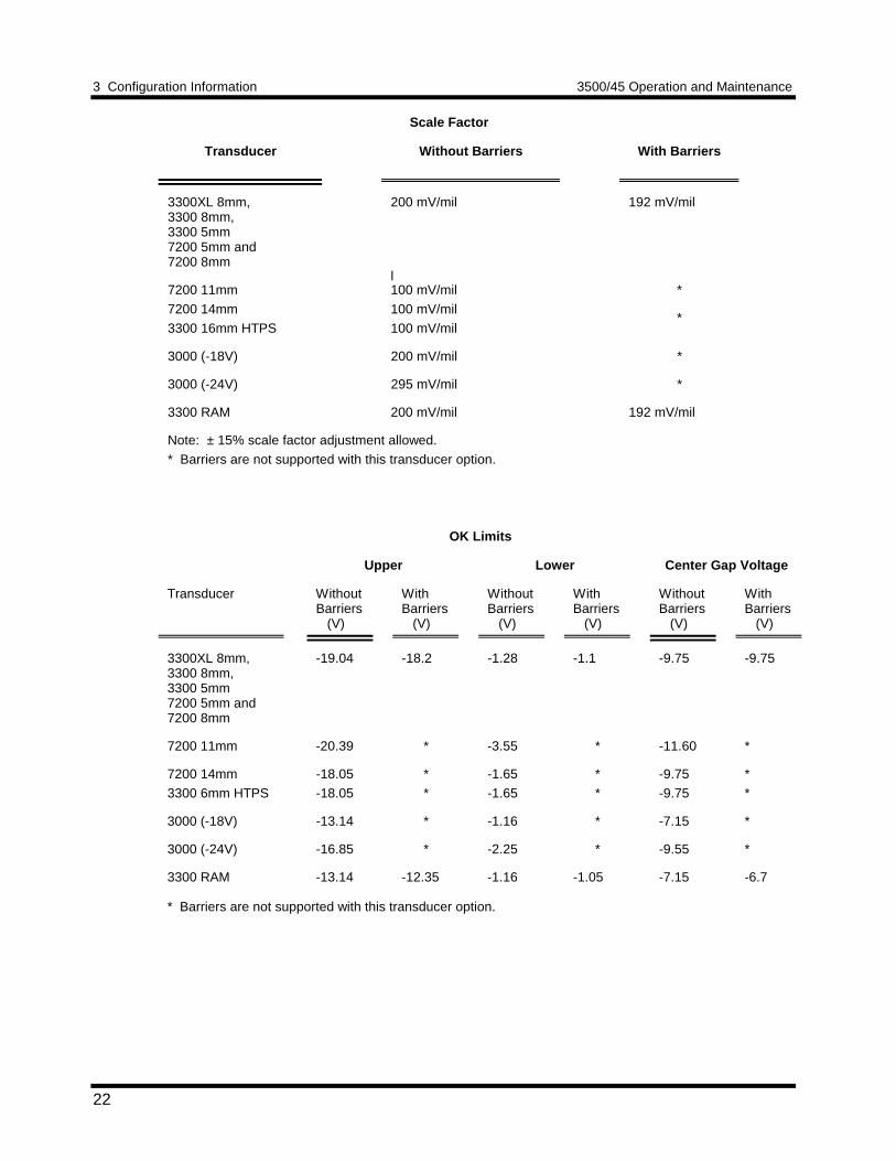
Scale Factor
Transducer Without Barriers With Barriers
3300XL 8mm,3300 8mm,3300 5mm7200 5mm and7200 8mm
200 mV/mil 192 mV/mil
7200 11mml100 mV/mil *
7200 14mm
3300 16mm HTPS
100 mV/mil
100 mV/mil*
3000 (-18V) 200 mV/mil *
3000 (-24V) 295 mV/mil *
3300 RAM 200 mV/mil 192 mV/mil
Note: ± 15% scale factor adjustment allowed.
* Barriers are not supported with this transducer option.
OK Limits
Upper Lower Center Gap Voltage
Transducer WithoutBarriers (V)
WithBarriers (V)
WithoutBarriers (V)
WithBarriers (V)
WithoutBarriers (V)
WithBarriers (V)
3300XL 8mm,3300 8mm,3300 5mm7200 5mm and7200 8mm
-19.04 -18.2 -1.28 -1.1 -9.75 -9.75
7200 11mm -20.39 * -3.55 * -11.60 *
7200 14mm
3300 6mm HTPS
-18.05
-18.05
*
*
-1.65
-1.65
*
*
-9.75
-9.75
*
*
3000 (-18V) -13.14 * -1.16 * -7.15 *
3000 (-24V) -16.85 * -2.25 * -9.55 *
3300 RAM -13.14 -12.35 -1.16 -1.05 -7.15 -6.7
* Barriers are not supported with this transducer option.
3500/45 Operation and Maintenance 3 Configuration Information
23
Transducer Jumper Status (on I/O Module)Returns the position of the Transducer Jumper on the I/O Module. Refer toSection 4.1 (Setting the I/O Jumper) for the function of this jumper.
Alarm Mode
LatchingOnce an alarm is active it will remain active even after the proportional valuedrops below the configured setpoint level. The channel will remain in alarmuntil it is reset using one of the following methods:• the reset switch on the front of the Rack Interface Module• the contact on the Rack Interface I/O Module• the Reset button in the Operator Display Software• the reset command through the Communication Gateway Module
NonlatchingWhen an alarm is active it will go inactive as soon as the proportional valuedrops below the configured setpoint level.
Alert should be the first level alarm that occurs when the proportional valueexceeds the selected value. Danger should be the second level alarm thatoccurs when the proportional value exceeds the selected value. The Alert andDanger values are set on the Setpoint screen.
BarriersSelect the appropriate barrier option if external barriers are connected between themonitor and the transducer. Barriers are used to restrict the amount of energy thatcan flow into a hazardous area.
Normal Thrust DirectionThis field defines whether rotor movement toward or away from the thrust probecorresponds to a more positive thrust reading (for example upscale on a bar graph). Ifthis field is set to "Toward Probe", then as the rotor moves toward the thrust probe thethrust position direct proportional value will increase and go upscale on a bar graph.
3.1.3 Differential Expansion Channel OptionsThis section discusses the Configuration Considerations and the Rack ConfigurationSoftware screens associated with the Differential Expansion Channel.
3.1.3.1 Differential Expansion Channel Configuration ConsiderationsConsider the following items before configuring a Differential Expansion Channel:• The "No Keyphasor" option is automatically selected for this channel type. No
Keyphasors are required.• The Differential Expansion Direct full-scale range is dependent upon the
transducer type.• The Zero Position voltage range is dependent upon the direct full-scale range, the
upscale direction, and the transducer type.
3 Configuration Information 3500/45 Operation and Maintenance
24
• Monitors must be configured in channel pairs (for example, Channels 1 and 2 maybe configured as Differential Expansion and Channels 3 and 4 may be configuredas Ramp Differential Expansion).
• When a full-scale range is modified, the setpoints associated with this proportionalvalue should be readjusted.
• The Latching OK Mode and the Timed OK Channel Defeat options are notcompatible.
•
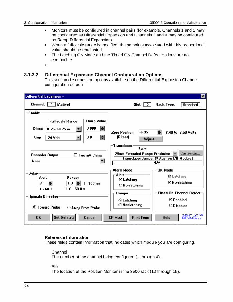
3.1.3.2 Differential Expansion Channel Configuration OptionsThis section describes the options available on the Differential Expansion Channelconfiguration screen
Reference InformationThese fields contain information that indicates which module you are configuring.
ChannelThe number of the channel being configured (1 through 4).
SlotThe location of the Position Monitor in the 3500 rack (12 through 15).
3500/45 Operation and Maintenance 3 Configuration Information
25
Rack TypeIdentifies the type of Rack Interface Module installed in the rack (Standard orTMR).
EnableDirectChange in axial position of the rotor relative to the probe. This value may bedisplayed in inches or millimetres. This proportional value supports both centerzero and noncenter zero full-scale ranges.
GapThe physical distance between the face of a proximity probe tip and the observedsurface. The distance is expressed in terms of voltage. Standard polarityconvention dictates that a decreasing gap results in an increasing (less negative)output signal.
Direct Full-scale Ranges by Transducer Type
25mm Extended Range Proximitor35mm Extended Range Proximitor
50mm Extended Range ProximitorNonstandard
5-0-5 mm0-10 mm0.25 - 0 - 0.25 in0.0 - 0.5 inCustom
5-0-5 mm0-10 mm10-0-10 mm0-20 mm0.25 - 0 - 0.25 in0.0 - 0.5 in0.5 - 0 - 0.5 in0.0 - 1.0 inCustom
The Gap Full-scale Ranges are the same for all transducer types.
Gap
-24 VdcCustom
Clamp ValueThe value that a proportional value goes to when that channel or proportional valueis bypassed or defeated (For example when a problem occurs with the transducer).The selected value can be between the minimum and maximum full-scale rangevalues. The values available from the Communication Gateway Module areclamped to the specified value when the proportional value is invalid. The recorderoutputs are also clamped to the specified value if 2mA clamp is not selected.
3 Configuration Information 3500/45 Operation and Maintenance
26
Recorder OutputThe proportional value of a channel that is sent to the 4 to 20 mA recorder. Therecorder output is proportional to the measured value over the channel full-scalerange. An increase in the proportional value that would be indicated as upscale ona bar graph display results in an increase in the current at the recorder output. Ifthe channel is bypassed, the output will be clamped to the selected clamp value orto 2 mA (if the 2 mA clamp is selected).
DelayThe time which a proportional value must remain at or above an over alarm level orbelow an under alarm level before an alarm is declared as active.
AlertFirst level alarm that occurs when the proportional value exceeds the selectedAlert/Alarm 1 setpoint. This setpoint can be set on the Setpoint screen. The Alerttime delay is always set at one second intervals (from 1 to 60) for all availableproportional values.
DangerSecond level alarm that occurs when the proportional value exceeds the selectedDanger/Alarm 2 setpoint. This setpoint can be set on the Setpoint screen.
100 ms (Typ.) optionThe 100 ms option applies to the Danger time delay only and has the followingresults:
If the 100 ms option is off ():• The Danger time delay can be set at one second intervals (from 1
through 60).• The Danger time delay can be set for all available proportional values.
If the 100 ms option is on ():• The Danger time delay is set to 100 ms.• The Danger time delay can only be set for the primary proportional
value.
Upscale DirectionTowards or away from the probe face. This field defines whether rotor movementtoward or away from the probe corresponds to positive differential expansion (forexample upscale on a bar graph). If this field is set to "Toward Probe", then as therotor moves toward the differential expansion probe the differential expansion directproportional value will increase and go upscale on a bar graph.
Zero Position (Direct)Represents the transducer DC voltage corresponding to the zero indication on thechannel's meter scale for the direct proportional value. The amount of adjustmentallowed is dependent upon the Direct Full-scale Range and the transducer OK limits.To ensure maximum amount of zero adjustment, gap the probe as close as possible tothe zero position voltage automatically displayed in the direct zero position voltagefield.
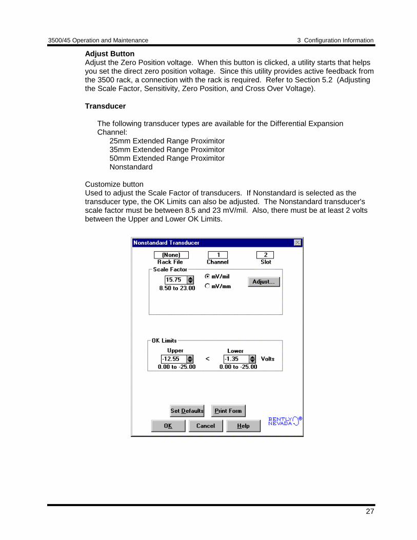
3500/45 Operation and Maintenance 3 Configuration Information
27
Adjust ButtonAdjust the Zero Position voltage. When this button is clicked, a utility starts that helpsyou set the direct zero position voltage. Since this utility provides active feedback fromthe 3500 rack, a connection with the rack is required. Refer to Section 5.2 (Adjustingthe Scale Factor, Sensitivity, Zero Position, and Cross Over Voltage).
Transducer
The following transducer types are available for the Differential ExpansionChannel:
25mm Extended Range Proximitor35mm Extended Range Proximitor50mm Extended Range ProximitorNonstandard
Customize buttonUsed to adjust the Scale Factor of transducers. If Nonstandard is selected as thetransducer type, the OK Limits can also be adjusted. The Nonstandard transducer'sscale factor must be between 8.5 and 23 mV/mil. Also, there must be at least 2 voltsbetween the Upper and Lower OK Limits.
3 Configuration Information 3500/45 Operation and Maintenance
28
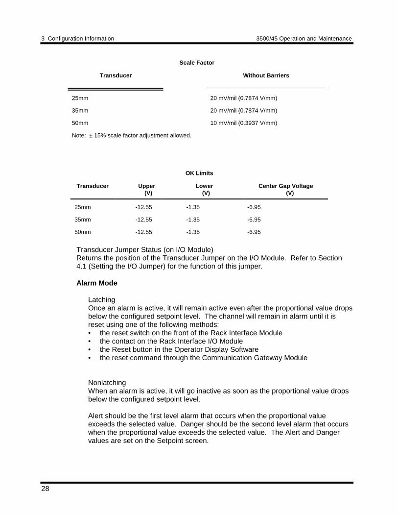
Scale Factor
Transducer Without Barriers
25mm 20 mV/mil (0.7874 V/mm)
35mm 20 mV/mil (0.7874 V/mm)
50mm 10 mV/mil (0.3937 V/mm)
Note: ± 15% scale factor adjustment allowed.
OK Limits
Transducer Upper (V)
Lower (V)
Center Gap Voltage (V)
25mm -12.55 -1.35 -6.95
35mm -12.55 -1.35 -6.95
50mm -12.55 -1.35 -6.95
Transducer Jumper Status (on I/O Module)Returns the position of the Transducer Jumper on the I/O Module. Refer to Section4.1 (Setting the I/O Jumper) for the function of this jumper.
Alarm Mode
LatchingOnce an alarm is active, it will remain active even after the proportional value dropsbelow the configured setpoint level. The channel will remain in alarm until it isreset using one of the following methods:• the reset switch on the front of the Rack Interface Module• the contact on the Rack Interface I/O Module• the Reset button in the Operator Display Software• the reset command through the Communication Gateway Module
NonlatchingWhen an alarm is active, it will go inactive as soon as the proportional value dropsbelow the configured setpoint level.
Alert should be the first level alarm that occurs when the proportional valueexceeds the selected value. Danger should be the second level alarm that occurswhen the proportional value exceeds the selected value. The Alert and Dangervalues are set on the Setpoint screen.
3500/45 Operation and Maintenance 3 Configuration Information
29
OK Mode
LatchingIf a channel is configured for Latching OK, once the channel has gone not OK thestatus stays not OK until the channel is in an OK condition and a reset is issued.Reset a latched not OK by using one of the following methods:• the reset switch on the front of the Rack Interface Module• the external contact closure on the Rack Interface I/O Module• the Reset button in the Operator Display Software• the reset command through the Communication Gateway Module
NonlatchingThe OK status of the channel will track the defined OK status of the transducer.
Timed OK Channel DefeatAn option that prevents a channel from returning to an OK status until that channel'stransducer has remained in an OK state for the specified period of time. If the optionis enabled, the time is set to 10 seconds. The option protects against false tripscaused by intermittent transducers. When this option is disabled, the channel will drivean alarm even when the channel is in the not OK state.
3.1.4 Ramp Differential Expansion Channel Pair OptionsThis section discusses the Configuration Considerations and the Rack ConfigurationSoftware screens associated with the Ramp Differential Expansion Channel Pair.
Three types of Ramp Differential Expansion monitoring can be configured. The threetypes are listed below and some examples are shown.
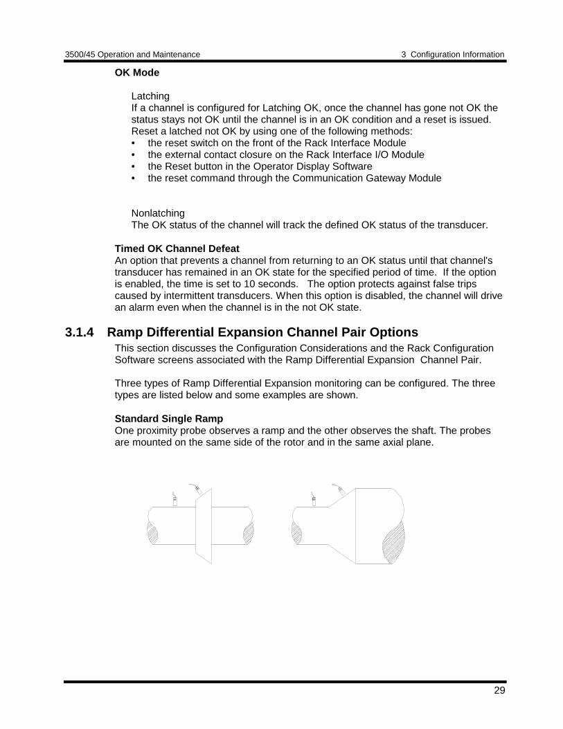
Standard Single RampOne proximity probe observes a ramp and the other observes the shaft. The probesare mounted on the same side of the rotor and in the same axial plane.
3 Configuration Information 3500/45 Operation and Maintenance
30
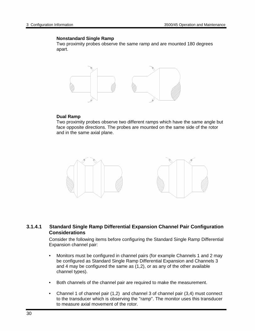
Nonstandard Single RampTwo proximity probes observe the same ramp and are mounted 180 degreesapart.
Dual RampTwo proximity probes observe two different ramps which have the same angle butface opposite directions. The probes are mounted on the same side of the rotorand in the same axial plane.
3.1.4.1 Standard Single Ramp Differential Expansion Channel Pair ConfigurationConsiderationsConsider the following items before configuring the Standard Single Ramp DifferentialExpansion channel pair:
• Monitors must be configured in channel pairs (for example Channels 1 and 2 maybe configured as Standard Single Ramp Differential Expansion and Channels 3and 4 may be configured the same as (1,2), or as any of the other availablechannel types).
• Both channels of the channel pair are required to make the measurement.
• Channel 1 of channel pair (1,2) and channel 3 of channel pair (3,4) must connectto the transducer which is observing the "ramp". The monitor uses this transducerto measure axial movement of the rotor.
3500/45 Operation and Maintenance 3 Configuration Information
31
• Channel 2 of channel pair (1,2) and channel 4 of channel pair (3,4) must beconnected to the transducer observing the "flat". This transducer measures radialmovement of the rotor. The monitor uses this measurement to correct the ramptransducer reading so that radial movement does not cause an apparent axialmovement.
• The differential expansion "composite" full-scale range is the axial rotor positioncompensated for the effect of rotor radial movement. The composite full-scalerange is selected by the user and this also determines the direct full-scale ranges.
• The ramp transducer zero position voltage depends on the transducer type, thefull-scale range, the ramp angle, and the upscale direction.
• The flat transducer zero position voltage depends only on the transducer type. Thisprobe is gapped at the midpoint of its range.
• The composite full-scale range, the ramp transducer type, and the ramp angle areinterdependent. This means that certain combinations are not allowed. As youwork on your configuration you may get various error messages and have theramp angle reset.
• The ramp transducer type and the flat transducer type can be different. However,the flat transducer's scale factor must be the same or more sensitive than the ramptransducer's scale factor. (For example, a 20 mV/mil ramp scale factor with a 200mV/mil flat scale factor is allowed. The reverse is not allowed.)
• When the composite full-scale range is modified, the setpoints associated with thisproportional value should be readjusted on both of the channels of the pair.
• The Latching OK Mode and the Not OK Channel Defeat options are notcompatible.
3 Configuration Information 3500/45 Operation and Maintenance
32
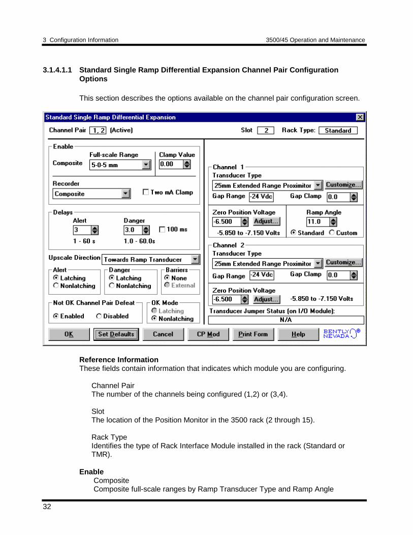
3.1.4.1.1 Standard Single Ramp Differential Expansion Channel Pair ConfigurationOptions
This section describes the options available on the channel pair configuration screen.
Reference InformationThese fields contain information that indicates which module you are configuring.
Channel PairThe number of the channels being configured (1,2) or (3,4).
SlotThe location of the Position Monitor in the 3500 rack (2 through 15).
Rack TypeIdentifies the type of Rack Interface Module installed in the rack (Standard orTMR).
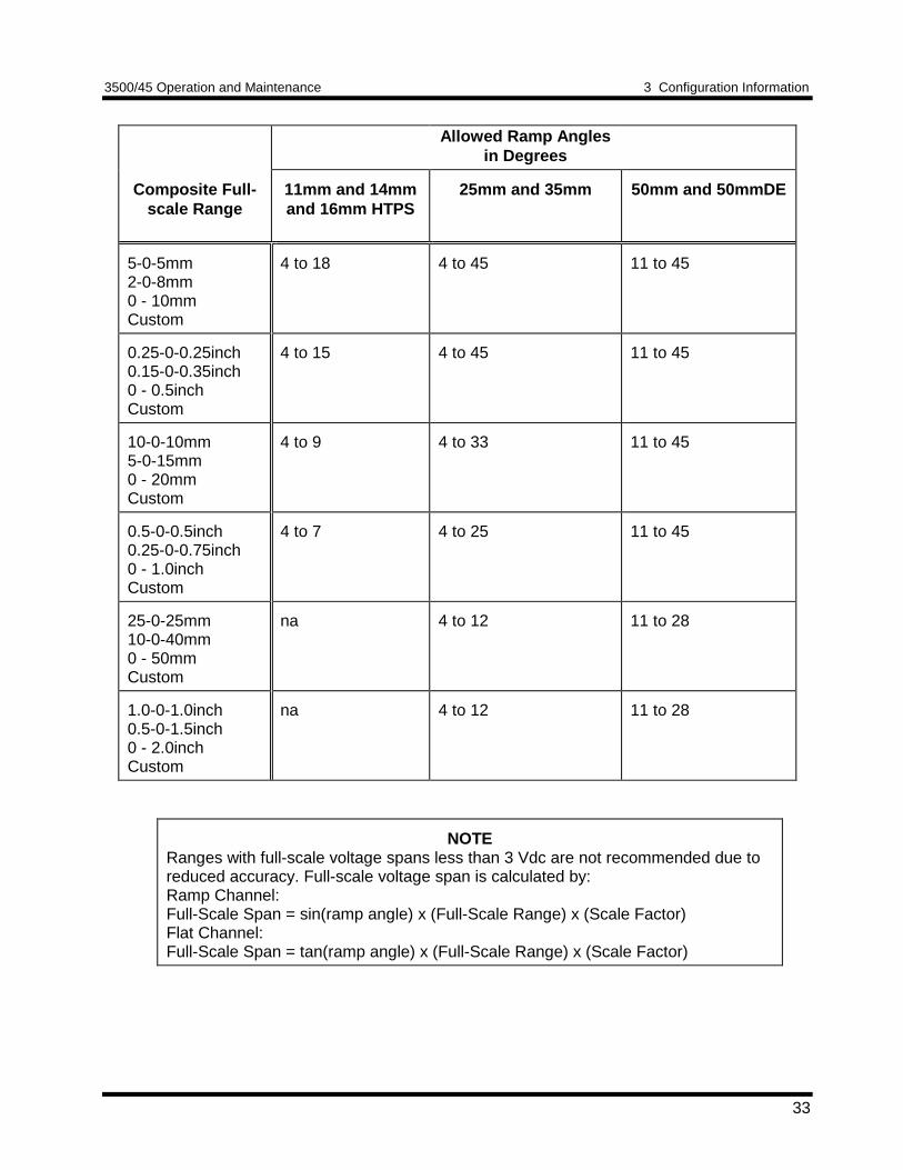
Enable Composite Composite full-scale ranges by Ramp Transducer Type and Ramp Angle
3500/45 Operation and Maintenance 3 Configuration Information
33
Allowed Ramp Anglesin Degrees
Composite Full-scale Range
11mm and 14mmand 16mm HTPS
25mm and 35mm 50mm and 50mmDE
5-0-5mm2-0-8mm0 - 10mmCustom
4 to 18 4 to 45 11 to 45
0.25-0-0.25inch0.15-0-0.35inch0 - 0.5inchCustom
4 to 15 4 to 45 11 to 45
10-0-10mm5-0-15mm0 - 20mmCustom
4 to 9 4 to 33 11 to 45
0.5-0-0.5inch0.25-0-0.75inch0 - 1.0inchCustom
4 to 7 4 to 25 11 to 45
25-0-25mm10-0-40mm0 - 50mmCustom
na 4 to 12 11 to 28
1.0-0-1.0inch0.5-0-1.5inch0 - 2.0inchCustom
na 4 to 12 11 to 28
NOTERanges with full-scale voltage spans less than 3 Vdc are not recommended due toreduced accuracy. Full-scale voltage span is calculated by:Ramp Channel:Full-Scale Span = sin(ramp angle) x (Full-Scale Range) x (Scale Factor)Flat Channel:Full-Scale Span = tan(ramp angle) x (Full-Scale Range) x (Scale Factor)
3 Configuration Information 3500/45 Operation and Maintenance
34
Clamp ValueThe value that the composite proportional value goes to when it is bypassed ordefeated (for example a problem with the transducer). The selected value can bebetween the minimum and maximum composite values. The value available from theCommunication Gateway Module is clamped to the specified value when theproportional value is invalid. The recorder outputs are also clamped to the specifiedvalue if 2mA clamp is not selected.
Recorder OutputThe proportional value sent to the 4 to 20 mA recorder. The composite proportionalvalue is the only selection. The recorder output is proportional to the measured valueof composite full-scale range. An increase in the composite proportional value whichindicates upscale on a bar graph display results in an increase in the current at therecorder output. If either channel of the channel pair is bypassed, the output will beclamped to the selected clamp value or to 2 mA (if the 2 mA clamp is selected).
DelayThe time which a proportional value must remain at or above an over alarm level orbelow an under alarm level before an alarm is declared as active.
AlertFirst level alarm that occurs when the proportional value exceeds the selectedAlert/Alarm 1 setpoint. This setpoint can be set on the Setpoint screen. The Alerttime delay is always set at one second intervals (from 1 to 60) for all availableproportional values.
DangerSecond level alarm that occurs when the proportional value exceeds the selectedDanger/Alarm 2 setpoint. This setpoint can be set on the Setpoint screen.
100 ms optionThe 100 ms (typical) option applies to the Danger time delay only and has thefollowing results:
If the 100 ms option is off ():• The Danger time delay can be set at one second intervals (from 1
through 60).• The Danger time delay can be set for any two available proportional
values.
If the 100 ms option is on ():• The Danger time delay is set to 100 ms.• The Danger time delay can only be set for the primary proportional
value.
3500/45 Operation and Maintenance 3 Configuration Information
35
Upscale DirectionTowards or away from the ramp probe. This field defines whether rotor movementtoward or away from the ramp probe corresponds to positive differential expansion (forexample upscale on a bar graph). If this field is set to "Toward Ramp Transducer",then as the rotor moves toward the ramp probe the differential expansion compositeproportional value will increase and go upscale on a bar graph.
Alarm ModeLatchingOnce an alarm is active, it will remain active even after the proportional value dropsbelow the configured setpoint level. The channel will remain in alarm until it isreset using one of the following methods:• the reset switch on the front of the Rack Interface Module• the contact on the Rack Interface I/O Module• the Reset button in the Operator Display Software• the reset command through the Communication Gateway Module
NonlatchingWhen an alarm is active, it will go inactive as soon as the proportional value dropsbelow the configured setpoint level.
Alert should be the first level alarm that occurs when the proportional valueexceeds the selected value. Danger should be the second level alarm that occurswhen the proportional value exceeds the selected value. The Alert and Dangervalues are set on the Setpoint screen.
BarriersSelect the external option if external barriers are connected between the monitor andthe transducer. Barriers are used to restrict the amount of energy that can flow into ahazardous area.
Not OK Channel Defeat When this option is disabled the channel will drive an alarm even when the channel isin the not OK state if the alarm setpoint has been exceeded for the delay time. Whenthe option is enabled this option will inhibit alarming if either channel of the channelpair goes to a not OK condition. In addition, when enabled, the not OK condition mustbe removed for 10 seconds before monitoring resumes.
OK Mode
LatchingIf a channel is configured for Latching OK, once the channel has gone not OK thestatus stays not OK until the channel is in an OK condition and a reset is issued.Reset a latched not OK by using one of the following methods:• the reset switch on the front of the Rack Interface Module• the external contact closure on the Rack Interface I/O Module• the Reset button in the Operator Display Software• the reset command through the Communication Gateway Module
3 Configuration Information 3500/45 Operation and Maintenance
36
NonlatchingThe OK status of the channel will track the defined OK status of the transducer.
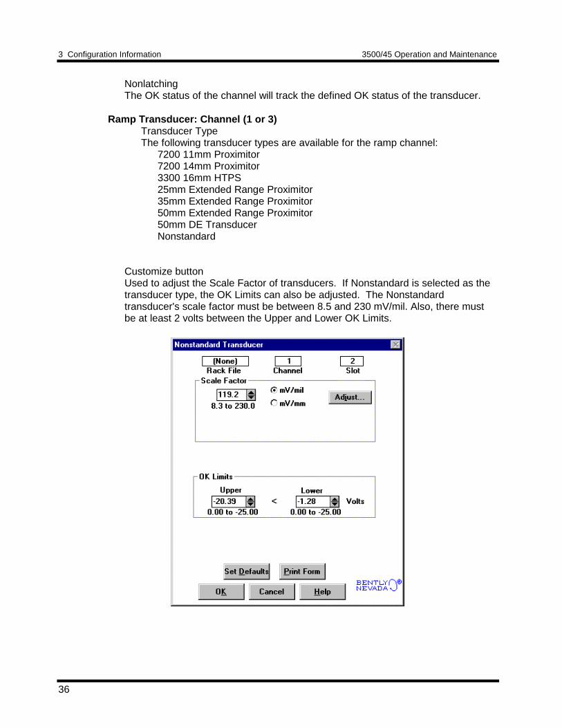
Ramp Transducer: Channel (1 or 3)Transducer TypeThe following transducer types are available for the ramp channel:
7200 11mm Proximitor7200 14mm Proximitor3300 16mm HTPS25mm Extended Range Proximitor35mm Extended Range Proximitor50mm Extended Range Proximitor50mm DE TransducerNonstandard
Customize buttonUsed to adjust the Scale Factor of transducers. If Nonstandard is selected as thetransducer type, the OK Limits can also be adjusted. The Nonstandardtransducer's scale factor must be between 8.5 and 230 mV/mil. Also, there mustbe at least 2 volts between the Upper and Lower OK Limits.
3500/45 Operation and Maintenance 3 Configuration Information
37
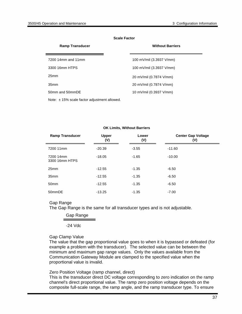
Scale Factor
Ramp Transducer Without Barriers
7200 14mm and 11mm
3300 16mm HTPS
25mm
100 mV/mil (3.3937 V/mm)
100 mV/mil (3.3937 V/mm)
20 mV/mil (0.7874 V/mm)
35mm 20 mV/mil (0.7874 V/mm)
50mm and 50mmDE 10 mV/mil (0.3937 V/mm)
Note: ± 15% scale factor adjustment allowed.
OK Limits, Without Barriers
Ramp Transducer Upper (V)
Lower (V)
Center Gap Voltage (V)
7200 11mm
7200 14mm3300 16mm HTPS
25mm
-20.39
-18.05
-12.55
-3.55
-1.65
-1.35
-11.60
-10.00
-6.50
35mm -12.55 -1.35 -6.50
50mm
50mmDE
-12.55
-13.25
-1.35
-1.35
-6.50
-7.00
Gap RangeThe Gap Range is the same for all transducer types and is not adjustable.
Gap Range
-24 Vdc
Gap Clamp ValueThe value that the gap proportional value goes to when it is bypassed or defeated (forexample a problem with the transducer). The selected value can be between theminimum and maximum gap range values. Only the values available from theCommunication Gateway Module are clamped to the specified value when theproportional value is invalid.
Zero Position Voltage (ramp channel, direct)This is the transducer direct DC voltage corresponding to zero indication on the rampchannel's direct proportional value. The ramp zero position voltage depends on thecomposite full-scale range, the ramp angle, and the ramp transducer type. To ensure
3 Configuration Information 3500/45 Operation and Maintenance
38
maximum dynamic range gap the probe as close as possible to the zero positionvoltage automatically displayed.
Adjust (ramp zero position voltage)Click this button to start a utility which helps you set the ramp direct zero positionvoltage. This utility provides active feedback from the 3500/45 monitor rack; therefore,a connection to the rack is required. Refer to Section 5.2 (Adjusting the Scale Factor,Sensitivity, Zero Position, and Cross Over Voltage).
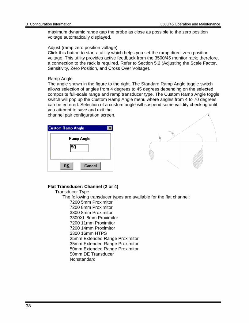
Ramp AngleThe angle shown in the figure to the right. The Standard Ramp Angle toggle switchallows selection of angles from 4 degrees to 45 degrees depending on the selectedcomposite full-scale range and ramp transducer type. The Custom Ramp Angle toggleswitch will pop up the Custom Ramp Angle menu where angles from 4 to 70 degreescan be entered. Selection of a custom angle will suspend some validity checking untilyou attempt to save and exit thechannel pair configuration screen.
Flat Transducer: Channel (2 or 4)Transducer Type
The following transducer types are available for the flat channel:7200 5mm Proximitor7200 8mm Proximitor3300 8mm Proximitor3300XL 8mm Proximitor7200 11mm Proximitor7200 14mm Proximitor3300 16mm HTPS25mm Extended Range Proximitor35mm Extended Range Proximitor50mm Extended Range Proximitor50mm DE TransducerNonstandard
3500/45 Operation and Maintenance 3 Configuration Information
39
Customize buttonUsed to adjust the Scale Factor of transducers. If Nonstandard is selected as thetransducer type, the OK Limits can also be adjusted. The nonstandardtransducer's scale factor must be between 8.5 and 230 mV/mil. Also, there mustbe at least 2 volts between the Upper and Lower OK Limits.
Scale Factor
Flat Transducer Without Barriers
3300XL 8mm, 3300 8mm,7200 5mm and 8mm
7200 14mm and 11mm3300 16mm HTPS
25mm
200 mV/mil (7.874 V/mm)
100 mV/mil (3.937 V/mm)
20 mV/mil (0.7874 V/mm)
35mm 20 mV/mil (0.7874 V/mm)
50mm and 50mm DE 10 mV/mil (0.3937 V/mm)
Note: ± 15% scale factor adjustment allowed.
3 Configuration Information 3500/45 Operation and Maintenance
40
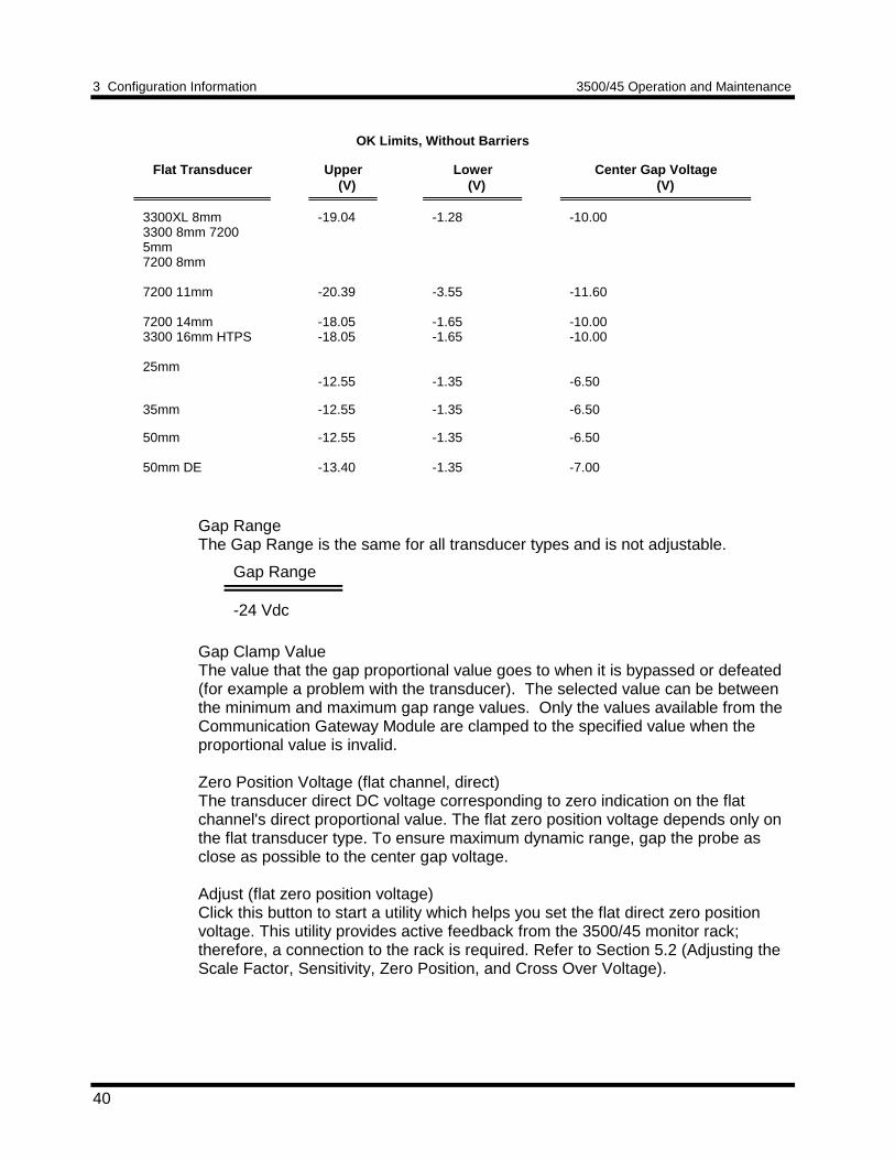
OK Limits, Without Barriers
Flat Transducer Upper (V)
Lower (V)
Center Gap Voltage (V)
3300XL 8mm3300 8mm 72005mm7200 8mm
7200 11mm
7200 14mm3300 16mm HTPS
25mm
-19.04
-20.39
-18.05-18.05
-12.55
-1.28
-3.55
-1.65-1.65
-1.35
-10.00
-11.60
-10.00-10.00
-6.50
35mm -12.55 -1.35 -6.50
50mm
50mm DE
-12.55
-13.40
-1.35
-1.35
-6.50
-7.00
Gap RangeThe Gap Range is the same for all transducer types and is not adjustable.
Gap Range
-24 Vdc
Gap Clamp ValueThe value that the gap proportional value goes to when it is bypassed or defeated(for example a problem with the transducer). The selected value can be betweenthe minimum and maximum gap range values. Only the values available from theCommunication Gateway Module are clamped to the specified value when theproportional value is invalid.
Zero Position Voltage (flat channel, direct)The transducer direct DC voltage corresponding to zero indication on the flatchannel's direct proportional value. The flat zero position voltage depends only onthe flat transducer type. To ensure maximum dynamic range, gap the probe asclose as possible to the center gap voltage.
Adjust (flat zero position voltage)Click this button to start a utility which helps you set the flat direct zero positionvoltage. This utility provides active feedback from the 3500/45 monitor rack;therefore, a connection to the rack is required. Refer to Section 5.2 (Adjusting theScale Factor, Sensitivity, Zero Position, and Cross Over Voltage).
3500/45 Operation and Maintenance 3 Configuration Information
41
Transducer Jumper Status (on I/O Module)Returns the position of the Transducer Jumper on the I/O Module. Refer toSection 4.1 (Setting the I/O Jumper) for the function of this jumper.
3.1.4.2 Nonstandard Single Ramp Differential Expansion Channel PairConfiguration ConsiderationsConsider the following items before configuring the Nonstandard Single RampDifferential Expansion channel pair:
• Monitors must be configured in channel pairs (for example Channels 1 and 2 maybe configured as Nonstandard Single Ramp Differential Expansion and Channels 3and 4 may be configured the same as (1,2), or as any of the other availablemonitor types).
• Both channels of the channel pair are required to make the measurement.
• The differential expansion full-scale range is the "composite" of the two channels.
• The differential expansion "composite" full-scale range is the axial rotor positioncompensated for the effect of rotor radial movement. The composite full-scalerange is selected by the user. The full-scale ranges for the individual transducersare determined by this selection.
• Upscale direction is the same for both transducers.
• The zero position voltages depend on the transducer type, the full-scale range, theramp angle, and the upscale direction.
• The two transducers must be the same type (same model number).
• The composite full-scale range, the transducer type, and the ramp angle areinterdependent. This means that certain combinations are not allowed.
• When the composite full-scale range is modified, the setpoints associated with thisproportional value should be readjusted on both of the channels of the pair.
• The Latching OK Mode and the Not OK Channel Defeat options are notcompatible.
3 Configuration Information 3500/45 Operation and Maintenance
42
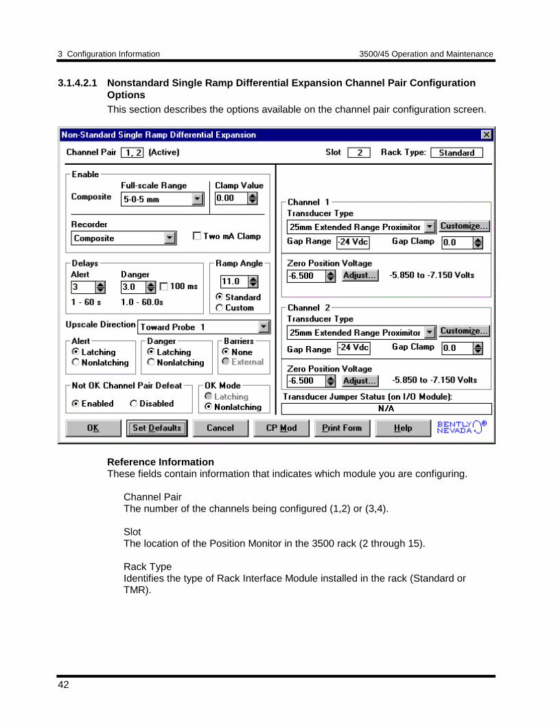
3.1.4.2.1 Nonstandard Single Ramp Differential Expansion Channel Pair ConfigurationOptionsThis section describes the options available on the channel pair configuration screen.
Reference InformationThese fields contain information that indicates which module you are configuring.
Channel PairThe number of the channels being configured (1,2) or (3,4).
SlotThe location of the Position Monitor in the 3500 rack (2 through 15).
Rack TypeIdentifies the type of Rack Interface Module installed in the rack (Standard orTMR).
3500/45 Operation and Maintenance 3 Configuration Information
43
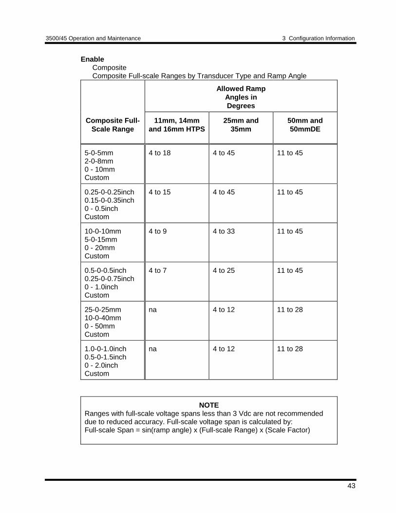
EnableCompositeComposite Full-scale Ranges by Transducer Type and Ramp Angle
Allowed RampAngles inDegrees
Composite Full-Scale Range
11mm, 14mmand 16mm HTPS
25mm and35mm
50mm and50mmDE
5-0-5mm2-0-8mm0 - 10mmCustom
4 to 18 4 to 45 11 to 45
0.25-0-0.25inch0.15-0-0.35inch0 - 0.5inchCustom
4 to 15 4 to 45 11 to 45
10-0-10mm5-0-15mm0 - 20mmCustom
4 to 9 4 to 33 11 to 45
0.5-0-0.5inch0.25-0-0.75inch0 - 1.0inchCustom
4 to 7 4 to 25 11 to 45
25-0-25mm10-0-40mm0 - 50mmCustom
na 4 to 12 11 to 28
1.0-0-1.0inch0.5-0-1.5inch0 - 2.0inchCustom
na 4 to 12 11 to 28
NOTERanges with full-scale voltage spans less than 3 Vdc are not recommendeddue to reduced accuracy. Full-scale voltage span is calculated by:Full-scale Span = sin(ramp angle) x (Full-scale Range) x (Scale Factor)
3 Configuration Information 3500/45 Operation and Maintenance
44
Clamp ValueThe value that the composite proportional value goes to when it is bypassed ordefeated (for example a problem with the transducer). The selected value can bebetween the minimum and maximum composite values. The value available from theCommunication Gateway Module is clamped to the specified value when theproportional value is invalid. The recorder outputs are also clamped to the specifiedvalue if 2mA clamp is not selected.
Recorder OutputThe proportional value sent to the 4 to 20 mA recorder. The composite proportionalvalue is the only selection. The recorder output is proportional to the measured valueof composite full-scale range. An increase in the composite proportional value whichindicates upscale on a bar graph display results in an increase in the current at therecorder output. If either channel of the channel pair is bypassed, the output will beclamped to the selected clamp value or to 2 mA (if the 2 mA clamp is selected).
DelayThe time which a proportional value must remain at or above an over alarm level orbelow an under alarm level before an alarm is declared as active.
AlertFirst level alarm that occurs when the proportional value exceeds the selectedAlert/Alarm 1 setpoint. This setpoint can be set on the Setpoint screen. The Alerttime delay is always set at one second intervals (from 1 to 60) for all availableproportional values.
DangerSecond level alarm that occurs when the proportional value exceeds the selectedDanger/Alarm 2 setpoint. This setpoint can be set on the Setpoint screen.
100 ms optionThe 100 ms (typical) option applies to the Danger time delay only and has thefollowing results:
If the 100 ms option is off ():• The Danger time delay can be set at one second intervals (from 1
through 60).• The Danger time delay can be set for any two available proportional
values.
If the 100 ms option is on ():• The Danger time delay is set to 100 ms.• The Danger time delay can only be set for the primary proportional
value.
3500/45 Operation and Maintenance 3 Configuration Information
45
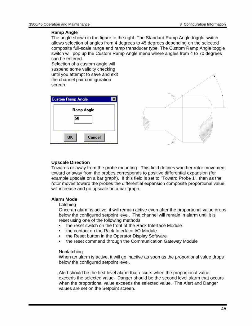
Ramp AngleThe angle shown in the figure to the right. The Standard Ramp Angle toggle switchallows selection of angles from 4 degrees to 45 degrees depending on the selectedcomposite full-scale range and ramp transducer type. The Custom Ramp Angle toggleswitch will pop up the Custom Ramp Angle menu where angles from 4 to 70 degreescan be entered.Selection of a custom angle willsuspend some validity checkinguntil you attempt to save and exitthe channel pair configurationscreen.
Upscale DirectionTowards or away from the probe mounting. This field defines whether rotor movementtoward or away from the probes corresponds to positive differential expansion (forexample upscale on a bar graph). If this field is set to "Toward Probe 1", then as therotor moves toward the probes the differential expansion composite proportional valuewill increase and go upscale on a bar graph.
Alarm ModeLatchingOnce an alarm is active, it will remain active even after the proportional value dropsbelow the configured setpoint level. The channel will remain in alarm until it isreset using one of the following methods:• the reset switch on the front of the Rack Interface Module• the contact on the Rack Interface I/O Module• the Reset button in the Operator Display Software• the reset command through the Communication Gateway Module
NonlatchingWhen an alarm is active, it will go inactive as soon as the proportional value dropsbelow the configured setpoint level.
Alert should be the first level alarm that occurs when the proportional valueexceeds the selected value. Danger should be the second level alarm that occurswhen the proportional value exceeds the selected value. The Alert and Dangervalues are set on the Setpoint screen.
3 Configuration Information 3500/45 Operation and Maintenance
46
BarriersSelect the external option if external barriers are connected between the monitor andthe transducer. Barriers are used to restrict the amount of energy that can flow into ahazardous area.
Not OK Channel DefeatWhen this option is disabled, the channel will drive an alarm even when the channel isin the not OK state if the alarm setpoint has been exceeded for the delay time. Whenenabled this option will inhibit alarming if either channel of the channel pair goes to anot OK condition. In addition, when the option is enabled, the not OK condition mustbe removed for 10 seconds before monitoring resumes.
OK ModeLatchingIf a channel is configured for Latching OK, once the channel has gone not OK thestatus stays not OK until the channel is in an OK condition and a reset is issued.Reset a latched not OK by using one of the following methods:• the reset switch on the front of the Rack Interface Module• the external contact closure on the Rack Interface I/O Module• the Reset button in the Operator Display Software• the reset command through the Communication Gateway Module
NonlatchingThe OK status of the channel will track the defined OK status of the transducer.
ChannelTransducer TypeThe following transducer types are available:
7200 11mm Proximitor7200 14mm Proximitor3300 16mm HTPS25mm Extended Range Proximitor35mm Extended Range Proximitor50mm Extended Range Proximitor50mm DE TransducerNonstandard
3500/45 Operation and Maintenance 3 Configuration Information
47
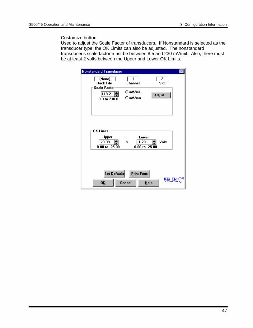
Customize buttonUsed to adjust the Scale Factor of transducers. If Nonstandard is selected as thetransducer type, the OK Limits can also be adjusted. The nonstandardtransducer's scale factor must be between 8.5 and 230 mV/mil. Also, there mustbe at least 2 volts between the Upper and Lower OK Limits.
3 Configuration Information 3500/45 Operation and Maintenance
48
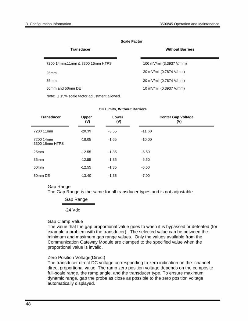
Scale Factor
Transducer Without Barriers
7200 14mm,11mm & 3300 16mm HTPS
25mm
100 mV/mil (3.3937 V/mm)
20 mV/mil (0.7874 V/mm)
35mm 20 mV/mil (0.7874 V/mm)
50mm and 50mm DE 10 mV/mil (0.3937 V/mm)
Note: ± 15% scale factor adjustment allowed.
OK Limits, Without Barriers
Transducer Upper (V)
Lower (V)
Center Gap Voltage (V)
7200 11mm
7200 14mm3300 16mm HTPS
25mm
-20.39
-18.05
-12.55
-3.55
-1.65
-1.35
-11.60
-10.00
-6.50
35mm -12.55 -1.35 -6.50
50mm
50mm DE
-12.55
-13.40
-1.35
-1.35
-6.50
-7.00
Gap RangeThe Gap Range is the same for all transducer types and is not adjustable.
Gap Range
-24 Vdc
Gap Clamp ValueThe value that the gap proportional value goes to when it is bypassed or defeated (forexample a problem with the transducer). The selected value can be between theminimum and maximum gap range values. Only the values available from theCommunication Gateway Module are clamped to the specified value when theproportional value is invalid.
Zero Position Voltage(Direct)The transducer direct DC voltage corresponding to zero indication on the channeldirect proportional value. The ramp zero position voltage depends on the compositefull-scale range, the ramp angle, and the transducer type. To ensure maximumdynamic range, gap the probe as close as possible to the zero position voltageautomatically displayed.
3500/45 Operation and Maintenance 3 Configuration Information
49
Adjust (zero position voltage, Direct)Click this button to start a utility which helps you set the ramp direct zero positionvoltage. This utility provides active feedback from the 3500/45 monitor rack;therefore, a connection to the rack is required. Refer to Section 5.2 (Adjusting theScale Factor, Sensitivity, Zero Position, and Cross Over Voltage).
Transducer Jumper Status (on I/O Module)Returns the position of the Transducer Jumper on the I/O Module. Refer toSection 4.1 (Setting the I/O Jumper) for the function of this jumper.
3.1.4.3 Dual Ramp Differential Expansion Channel Pair ConfigurationConsiderationsConsider the following items before configuring the Dual Ramp Differential Expansionchannel pair:
• Monitors must be configured in channel pairs (for example Channels 1 and 2 maybe configured as Dual Ramp Differential Expansion and Channels 3 and 4 may beconfigured the same as (1,2), or as any of the other available channel types).
• Both channels of the channel pair are required to make the measurement.
• The differential expansion full-scale range is the "composite" of the two channels.
• The differential expansion "composite" full-scale range is the axial rotor positioncompensated for the effect of rotor radial movement. The composite full-scalerange is selected by the user. The full-scale ranges for the individual transducersare determined by this selection.
• Upscale direction is referenced to the channel 1 or channel 3 probe.
• The zero position voltages depend on the transducer type, the full-scale range, theramp angle, and the upscale direction.
• The two transducers must be the same type (same model number).
• The composite full-scale range, the transducer type, and the ramp angle areinterdependent. This means that certain combinations are not allowed.
• When the composite full-scale range is modified, the setpoints associated with thisproportional value should be readjusted on both of the channels of the pair.
• The Latching OK Mode and the Not OK Channel Defeat options are notcompatible.
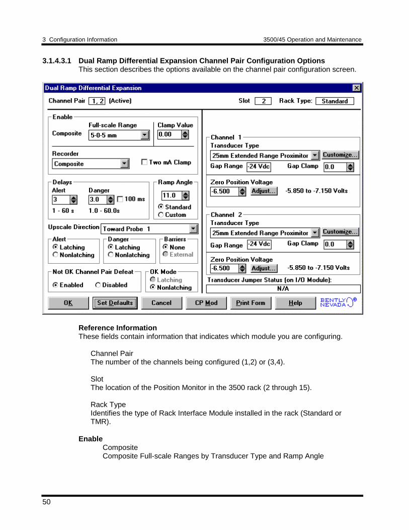
3 Configuration Information 3500/45 Operation and Maintenance
50
3.1.4.3.1 Dual Ramp Differential Expansion Channel Pair Configuration OptionsThis section describes the options available on the channel pair configuration screen.
Reference InformationThese fields contain information that indicates which module you are configuring.
Channel PairThe number of the channels being configured (1,2) or (3,4).
SlotThe location of the Position Monitor in the 3500 rack (2 through 15).
Rack TypeIdentifies the type of Rack Interface Module installed in the rack (Standard orTMR).
EnableCompositeComposite Full-scale Ranges by Transducer Type and Ramp Angle

3500/45 Operation and Maintenance 3 Configuration Information
51
Allowed RampAngles inDegrees
Composite Full-Scale Range
11mm, 14mmand 16mm HTPS
25mm and35mm
50mm and50mmDE
5-0-5mm2-0-8mm0 - 10mmCustom
4 to 18 4 to 45 11 to 45
0.25-0-0.25inch0.15-0-0.35inch0 - 0.5inchCustom
4 to 15 4 to 45 11 to 45
10-0-10mm5-0-15mm0 - 20mmCustom
4 to 9 4 to 33 11 to 45
0.5-0-0.5inch0.25-0-0.75inch0 - 1.0inchCustom
4 to 7 4 to 25 11 to 45
25-0-25mm10-0-40mm0 - 50mmCustom
na 4 to 12 11 to 28
1.0-0-1.0inch0.5-0-1.5inch0 - 2.0inchCustom
na 4 to 12 11 to 28
NOTERanges with full-scale voltage span less than 3 Vdc are not recommendeddue to reduced accuracy. Full-scale voltage span is calculated by:Full-scale Span = sin(ramp angle) x (Full-scale Range) x (Scale Factor)
3 Configuration Information 3500/45 Operation and Maintenance
52
Clamp ValueThe value that the composite proportional value goes to when it is bypassed ordefeated (for example a problem with the transducer). The selected value can bebetween the minimum and maximum composite values. The value available from theCommunication Gateway Module is clamped to the specified value when theproportional value is invalid. The recorder outputs are also clamped to the specifiedvalue if 2mA clamp is not selected.
Recorder OutputThe proportional value sent to the 4 to 20 mA recorder. The composite proportionalvalue is the only selection. The recorder output is proportional to the measured valueof composite full-scale range. An increase in the composite proportional value whichindicates upscale on a bar graph display results in an increase in the current at therecorder output. If either channel of the channel pair is bypassed, the output will beclamped to the selected clamp value or to 2 mA (if the 2 mA clamp is selected).
DelayThe time which a proportional value must remain at or above an over alarm level orbelow an under alarm level before an alarm is declared as active.
AlertFirst level alarm that occurs when the proportional value exceeds the selectedAlert/Alarm 1 setpoint. This setpoint can be set on the Setpoint screen. The Alerttime delay is always set at one second intervals (from 1 to 60) for all availableproportional values.
DangerSecond level alarm that occurs when the proportional value exceeds the selectedDanger/Alarm 2 setpoint. This setpoint can be set on the Setpoint screen.
100 ms optionThe 100 ms (typical) option applies to the Danger time delay only and has thefollowing results:
If the 100 ms option is off ():• The Danger time delay can be set at one second intervals (from 1 to
60).• The Danger time delay can be set for any two available proportional
values.
If the 100 ms option is on ():• The Danger time delay is set to 100 ms.• The Danger time delay can only be set for the primary proportional
value.
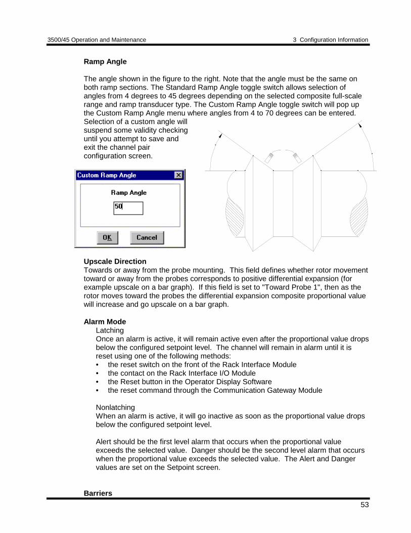
3500/45 Operation and Maintenance 3 Configuration Information
53
Ramp Angle
The angle shown in the figure to the right. Note that the angle must be the same onboth ramp sections. The Standard Ramp Angle toggle switch allows selection ofangles from 4 degrees to 45 degrees depending on the selected composite full-scalerange and ramp transducer type. The Custom Ramp Angle toggle switch will pop upthe Custom Ramp Angle menu where angles from 4 to 70 degrees can be entered.Selection of a custom angle willsuspend some validity checkinguntil you attempt to save andexit the channel pairconfiguration screen.
Upscale DirectionTowards or away from the probe mounting. This field defines whether rotor movementtoward or away from the probes corresponds to positive differential expansion (forexample upscale on a bar graph). If this field is set to "Toward Probe 1", then as therotor moves toward the probes the differential expansion composite proportional valuewill increase and go upscale on a bar graph.
Alarm ModeLatchingOnce an alarm is active, it will remain active even after the proportional value dropsbelow the configured setpoint level. The channel will remain in alarm until it isreset using one of the following methods:• the reset switch on the front of the Rack Interface Module• the contact on the Rack Interface I/O Module• the Reset button in the Operator Display Software• the reset command through the Communication Gateway Module
NonlatchingWhen an alarm is active, it will go inactive as soon as the proportional value dropsbelow the configured setpoint level.
Alert should be the first level alarm that occurs when the proportional valueexceeds the selected value. Danger should be the second level alarm that occurswhen the proportional value exceeds the selected value. The Alert and Dangervalues are set on the Setpoint screen.
Barriers
3 Configuration Information 3500/45 Operation and Maintenance
54
Select the external option if external barriers are connected between the monitor andthe transducer. Barriers are used to restrict the amount of energy that can flow into ahazardous area.
Not OK Channel DefeatWhen this option is disabled the channel will drive an alarm even when the channel isin the not OK state if the alarm setpoint has been exceeded for the delay time. Whenenabled this option will inhibit alarming if either channel of the channel pair goes to anot OK condition. In addition, when this option is enabled, the not OK condition mustbe removed for 10 seconds before monitoring resumes.
OK Mode
LatchingIf a channel is configured for Latching OK, once the channel has gone not OK thestatus stays not OK until the channel is in an OK condition and a reset is issued.Reset a latched not OK by using one of the following methods:• the reset switch on the front of the Rack Interface Module• the external contact closure on the Rack Interface I/O Module• the Reset button in the Operator Display Software• the reset command through the Communication Gateway Module
NonlatchingThe OK status of the channel will track the defined OK status of the transducer.
ChannelTransducer TypeThe following transducer types are available:
7200 11mm Proximitor7200 14mm Proximitor3300 16mm HTPS25mm Extended Range Proximitor35mm Extended Range Proximitor50mm Extended Range Proximitor50mm DE TransducerNonstandard
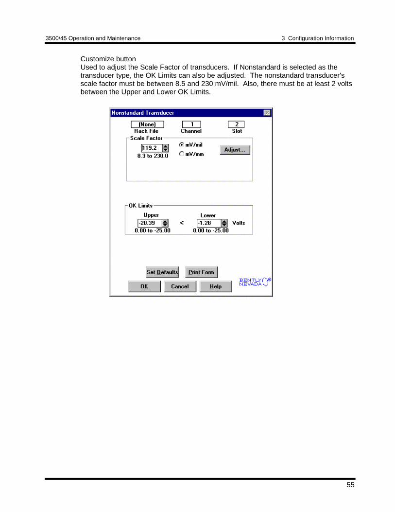
3500/45 Operation and Maintenance 3 Configuration Information
55
Customize buttonUsed to adjust the Scale Factor of transducers. If Nonstandard is selected as thetransducer type, the OK Limits can also be adjusted. The nonstandard transducer'sscale factor must be between 8.5 and 230 mV/mil. Also, there must be at least 2 voltsbetween the Upper and Lower OK Limits.
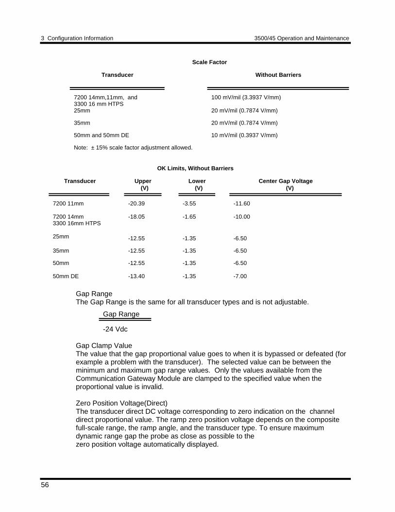
3 Configuration Information 3500/45 Operation and Maintenance
56
Scale Factor
Transducer Without Barriers
7200 14mm,11mm, and3300 16 mm HTPS25mm
100 mV/mil (3.3937 V/mm)
20 mV/mil (0.7874 V/mm)
35mm 20 mV/mil (0.7874 V/mm)
50mm and 50mm DE 10 mV/mil (0.3937 V/mm)
Note: ± 15% scale factor adjustment allowed.
OK Limits, Without Barriers
Transducer Upper (V)
Lower (V)
Center Gap Voltage (V)
7200 11mm
7200 14mm3300 16mm HTPS
25mm
-20.39
-18.05
-12.55
-3.55
-1.65
-1.35
-11.60
-10.00
-6.50
35mm -12.55 -1.35 -6.50
50mm
50mm DE
-12.55
-13.40
-1.35
-1.35
-6.50
-7.00
Gap RangeThe Gap Range is the same for all transducer types and is not adjustable.
Gap Range
-24 Vdc
Gap Clamp ValueThe value that the gap proportional value goes to when it is bypassed or defeated (forexample a problem with the transducer). The selected value can be between theminimum and maximum gap range values. Only the values available from theCommunication Gateway Module are clamped to the specified value when theproportional value is invalid.
Zero Position Voltage(Direct)The transducer direct DC voltage corresponding to zero indication on the channeldirect proportional value. The ramp zero position voltage depends on the compositefull-scale range, the ramp angle, and the transducer type. To ensure maximumdynamic range gap the probe as close as possible to thezero position voltage automatically displayed.
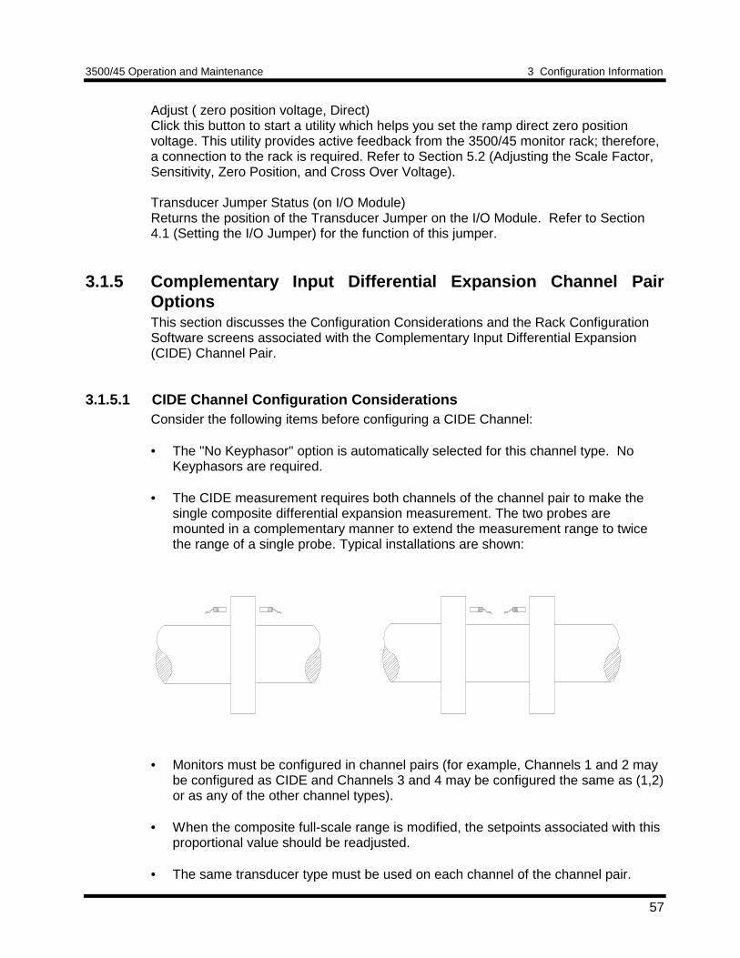
3500/45 Operation and Maintenance 3 Configuration Information
57
Adjust ( zero position voltage, Direct)Click this button to start a utility which helps you set the ramp direct zero positionvoltage. This utility provides active feedback from the 3500/45 monitor rack; therefore,a connection to the rack is required. Refer to Section 5.2 (Adjusting the Scale Factor,Sensitivity, Zero Position, and Cross Over Voltage).
Transducer Jumper Status (on I/O Module)Returns the position of the Transducer Jumper on the I/O Module. Refer to Section4.1 (Setting the I/O Jumper) for the function of this jumper.
3.1.5 Complementary Input Differential Expansion Channel PairOptionsThis section discusses the Configuration Considerations and the Rack ConfigurationSoftware screens associated with the Complementary Input Differential Expansion(CIDE) Channel Pair.
3.1.5.1 CIDE Channel Configuration ConsiderationsConsider the following items before configuring a CIDE Channel:
• The "No Keyphasor" option is automatically selected for this channel type. NoKeyphasors are required.
• The CIDE measurement requires both channels of the channel pair to make thesingle composite differential expansion measurement. The two probes aremounted in a complementary manner to extend the measurement range to twicethe range of a single probe. Typical installations are shown:
• Monitors must be configured in channel pairs (for example, Channels 1 and 2 maybe configured as CIDE and Channels 3 and 4 may be configured the same as (1,2)or as any of the other channel types).
• When the composite full-scale range is modified, the setpoints associated with thisproportional value should be readjusted.
• The same transducer type must be used on each channel of the channel pair.
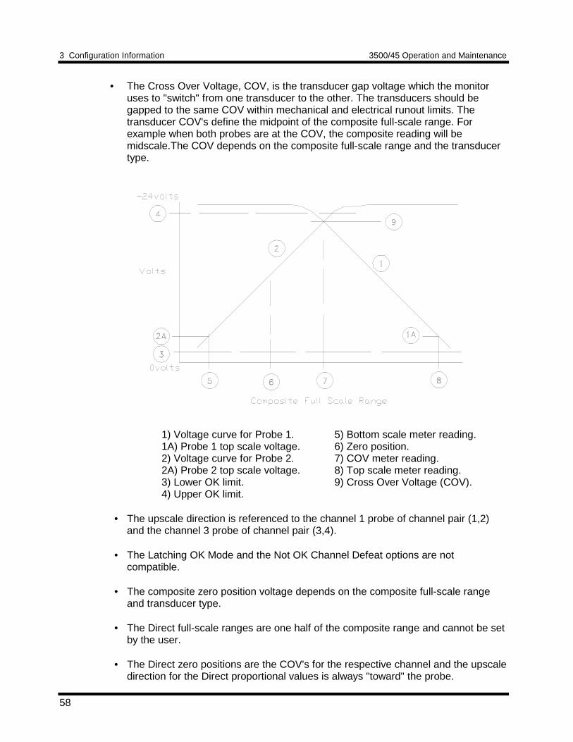
3 Configuration Information 3500/45 Operation and Maintenance
58
• The Cross Over Voltage, COV, is the transducer gap voltage which the monitoruses to "switch" from one transducer to the other. The transducers should begapped to the same COV within mechanical and electrical runout limits. Thetransducer COV's define the midpoint of the composite full-scale range. Forexample when both probes are at the COV, the composite reading will bemidscale.The COV depends on the composite full-scale range and the transducertype.
1) Voltage curve for Probe 1.1A) Probe 1 top scale voltage.2) Voltage curve for Probe 2.2A) Probe 2 top scale voltage.3) Lower OK limit.4) Upper OK limit.
5) Bottom scale meter reading.6) Zero position.7) COV meter reading.8) Top scale meter reading.9) Cross Over Voltage (COV).
• The upscale direction is referenced to the channel 1 probe of channel pair (1,2)and the channel 3 probe of channel pair (3,4).
• The Latching OK Mode and the Not OK Channel Defeat options are notcompatible.
• The composite zero position voltage depends on the composite full-scale rangeand transducer type.
• The Direct full-scale ranges are one half of the composite range and cannot be setby the user.
• The Direct zero positions are the COV's for the respective channel and the upscaledirection for the Direct proportional values is always "toward" the probe.
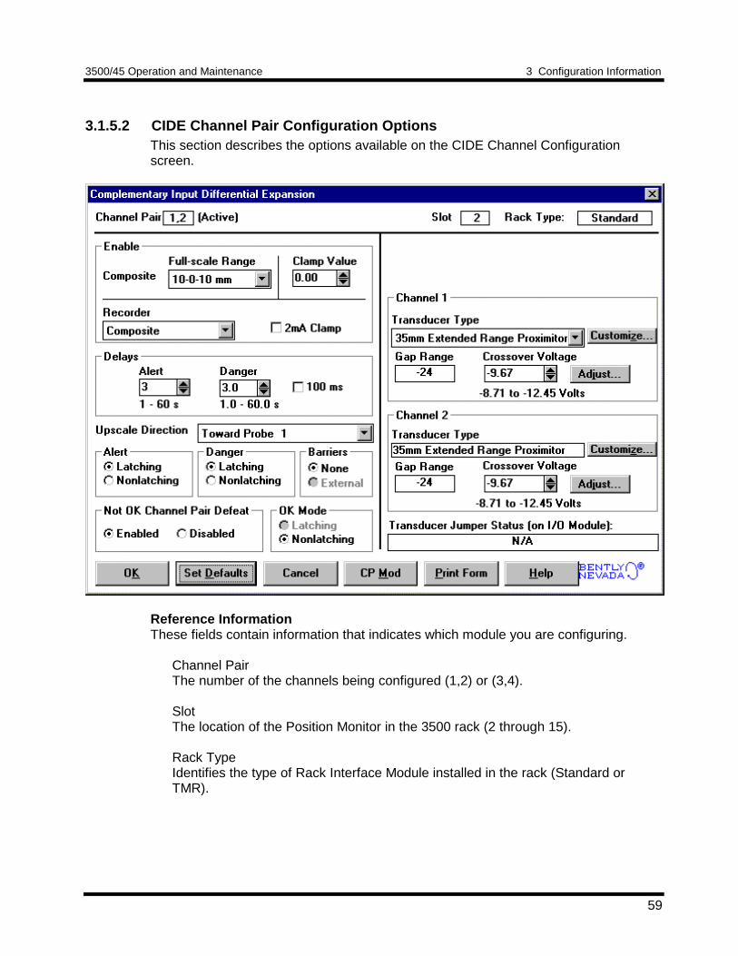
3500/45 Operation and Maintenance 3 Configuration Information
59
3.1.5.2 CIDE Channel Pair Configuration OptionsThis section describes the options available on the CIDE Channel Configurationscreen.
Reference InformationThese fields contain information that indicates which module you are configuring.
Channel PairThe number of the channels being configured (1,2) or (3,4).
SlotThe location of the Position Monitor in the 3500 rack (2 through 15).
Rack TypeIdentifies the type of Rack Interface Module installed in the rack (Standard orTMR).
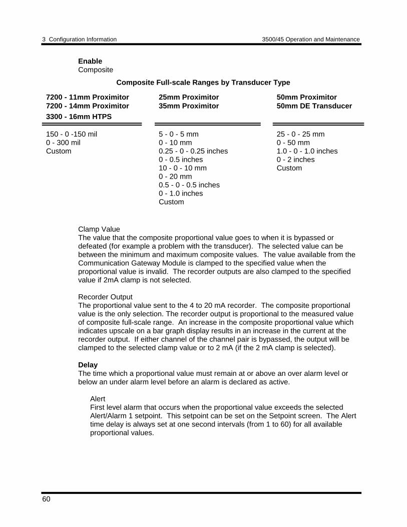
3 Configuration Information 3500/45 Operation and Maintenance
60
EnableComposite
Composite Full-scale Ranges by Transducer Type
7200 - 11mm Proximitor7200 - 14mm Proximitor3300 - 16mm HTPS
25mm Proximitor35mm Proximitor
50mm Proximitor50mm DE Transducer
150 - 0 -150 mil0 - 300 milCustom
5 - 0 - 5 mm0 - 10 mm0.25 - 0 - 0.25 inches0 - 0.5 inches10 - 0 - 10 mm0 - 20 mm0.5 - 0 - 0.5 inches0 - 1.0 inchesCustom
25 - 0 - 25 mm0 - 50 mm1.0 - 0 - 1.0 inches0 - 2 inchesCustom
Clamp ValueThe value that the composite proportional value goes to when it is bypassed ordefeated (for example a problem with the transducer). The selected value can bebetween the minimum and maximum composite values. The value available from theCommunication Gateway Module is clamped to the specified value when theproportional value is invalid. The recorder outputs are also clamped to the specifiedvalue if 2mA clamp is not selected.
Recorder OutputThe proportional value sent to the 4 to 20 mA recorder. The composite proportionalvalue is the only selection. The recorder output is proportional to the measured valueof composite full-scale range. An increase in the composite proportional value whichindicates upscale on a bar graph display results in an increase in the current at therecorder output. If either channel of the channel pair is bypassed, the output will beclamped to the selected clamp value or to 2 mA (if the 2 mA clamp is selected).
DelayThe time which a proportional value must remain at or above an over alarm level orbelow an under alarm level before an alarm is declared as active.
AlertFirst level alarm that occurs when the proportional value exceeds the selectedAlert/Alarm 1 setpoint. This setpoint can be set on the Setpoint screen. The Alerttime delay is always set at one second intervals (from 1 to 60) for all availableproportional values.
3500/45 Operation and Maintenance 3 Configuration Information
61
DangerSecond level alarm that occurs when the proportional value exceeds the selectedDanger/Alarm 2 setpoint. This setpoint can be set on the Setpoint screen.
100 ms optionThe 100 ms (typical) option applies to the Danger time delay only and has thefollowing results:
If the 100 ms option is off ():• The Danger time delay can be set at one second intervals (from 1 to 60).• The Danger time delay can be set for any two available proportional values.
If the 100 ms option is on ():• The Danger time delay is set to 100 ms.• The Danger time delay can only be set for the primary proportional value.
Upscale DirectionChannel 1 is the reference probe for channel pair (1,2) and channel 3 probe is thereference probe for channel pair (3,4). This field defines whether rotor movementtoward or away from the channel 1 probe for channel pair (1,2) or the channel 3 probefor pair (3,4) corresponds to positive differential expansion (for example upscale on abar graph). If this field is set to "Toward Probe 1", then as the rotor moves toward thechannel 1 probe the differential expansion composite proportional value will increaseand go upscale on a bar graph.
Alarm Mode
LatchingOnce an alarm is active, it will remain active even after the proportional value dropsbelow the configured setpoint level. The channel will remain in alarm until it isreset using one of the following methods:• the reset switch on the front of the Rack Interface Module• the contact on the Rack Interface I/O Module• the Reset button in the Operator Display Software• the reset command through the Communication Gateway Module
NonlatchingWhen an alarm is active, it will go inactive as soon as the proportional value dropsbelow the configured setpoint level.
Alert should be the first level alarm that occurs when the proportional valueexceeds the selected value. Danger should be the second level alarm that occurswhen the proportional value exceeds the selected value. The Alert and Dangervalues are set on the Setpoint screen.

3 Configuration Information 3500/45 Operation and Maintenance
62
BarriersSelect the external option if external barriers are connected between the monitor andthe transducer. Barriers are used to restrict the amount of energy that can flow into ahazardous area.
Not OK Channel Pair DefeatWhen this option is disabled the CIDE channel pair will drive an alarm even when thechannel pair is in the not OK state if the alarm setpoint has been exceeded for thedelay time. When enabled this option will inhibit alarming if the channel pair goes to anot OK condition. In addition, when this option is enabled, the not OK condition mustbe removed for 10 seconds before monitoring resumes.
OK ModeLatchingIf the channel pair is configured for Latching OK, once the channel pair has gonenot OK the status stays not OK until the channel is in an OK condition and a resetis issued. Reset a latched not OK by using one of the following methods:• the reset switch on the front of the Rack Interface Module• the external contact closure on the Rack Interface I/O Module• the Reset button in the Operator Display Software• the reset command through the Communication Gateway Module
NonlatchingThe OK status of the channel pair will track the defined OK status of thetransducer.
ChannelTransducer TypeThe following transducer types are available:
7200 11mm Proximitor7200 14mm Proximitor3300 16mm HTPS25mm Extended Range Proximitor35mm Extended Range Proximitor50mm Extended Range Proximitor50mm DE TransducerNonstandard
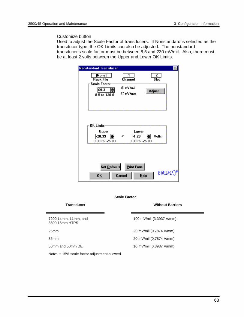
3500/45 Operation and Maintenance 3 Configuration Information
63
Customize buttonUsed to adjust the Scale Factor of transducers. If Nonstandard is selected as thetransducer type, the OK Limits can also be adjusted. The nonstandardtransducer's scale factor must be between 8.5 and 230 mV/mil. Also, there mustbe at least 2 volts between the Upper and Lower OK Limits.
Scale Factor
Transducer Without Barriers
7200 14mm, 11mm, and3300 16mm HTPS
25mm
100 mV/mil (3.3937 V/mm)
20 mV/mil (0.7874 V/mm)
35mm 20 mV/mil (0.7874 V/mm)
50mm and 50mm DE 10 mV/mil (0.3937 V/mm)
Note: ± 15% scale factor adjustment allowed.
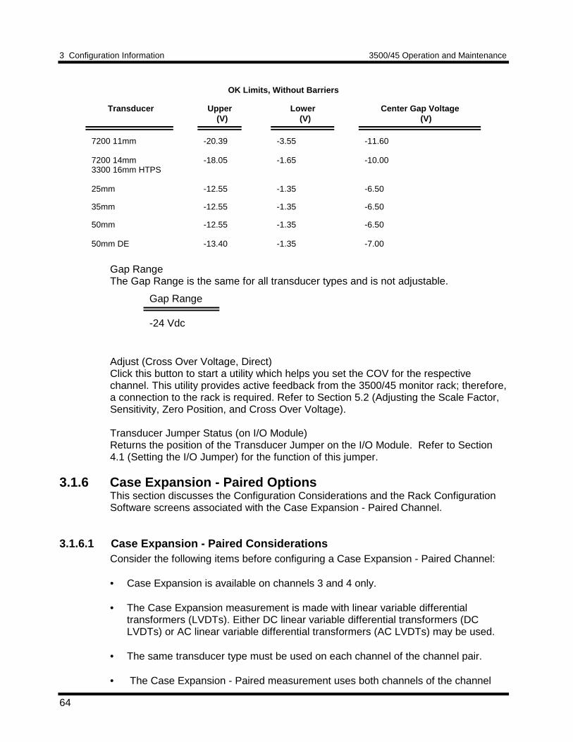
3 Configuration Information 3500/45 Operation and Maintenance
64
OK Limits, Without Barriers
Transducer Upper (V)
Lower (V)
Center Gap Voltage (V)
7200 11mm
7200 14mm3300 16mm HTPS
25mm
-20.39
-18.05
-12.55
-3.55
-1.65
-1.35
-11.60
-10.00
-6.50
35mm -12.55 -1.35 -6.50
50mm
50mm DE
-12.55
-13.40
-1.35
-1.35
-6.50
-7.00
Gap RangeThe Gap Range is the same for all transducer types and is not adjustable.
Gap Range
-24 Vdc
Adjust (Cross Over Voltage, Direct)Click this button to start a utility which helps you set the COV for the respectivechannel. This utility provides active feedback from the 3500/45 monitor rack; therefore,a connection to the rack is required. Refer to Section 5.2 (Adjusting the Scale Factor,Sensitivity, Zero Position, and Cross Over Voltage).
Transducer Jumper Status (on I/O Module)Returns the position of the Transducer Jumper on the I/O Module. Refer to Section4.1 (Setting the I/O Jumper) for the function of this jumper.
3.1.6 Case Expansion - Paired OptionsThis section discusses the Configuration Considerations and the Rack ConfigurationSoftware screens associated with the Case Expansion - Paired Channel.
3.1.6.1 Case Expansion - Paired ConsiderationsConsider the following items before configuring a Case Expansion - Paired Channel:
• Case Expansion is available on channels 3 and 4 only.
• The Case Expansion measurement is made with linear variable differentialtransformers (LVDTs). Either DC linear variable differential transformers (DCLVDTs) or AC linear variable differential transformers (AC LVDTs) may be used.
• The same transducer type must be used on each channel of the channel pair.
• The Case Expansion - Paired measurement uses both channels of the channel
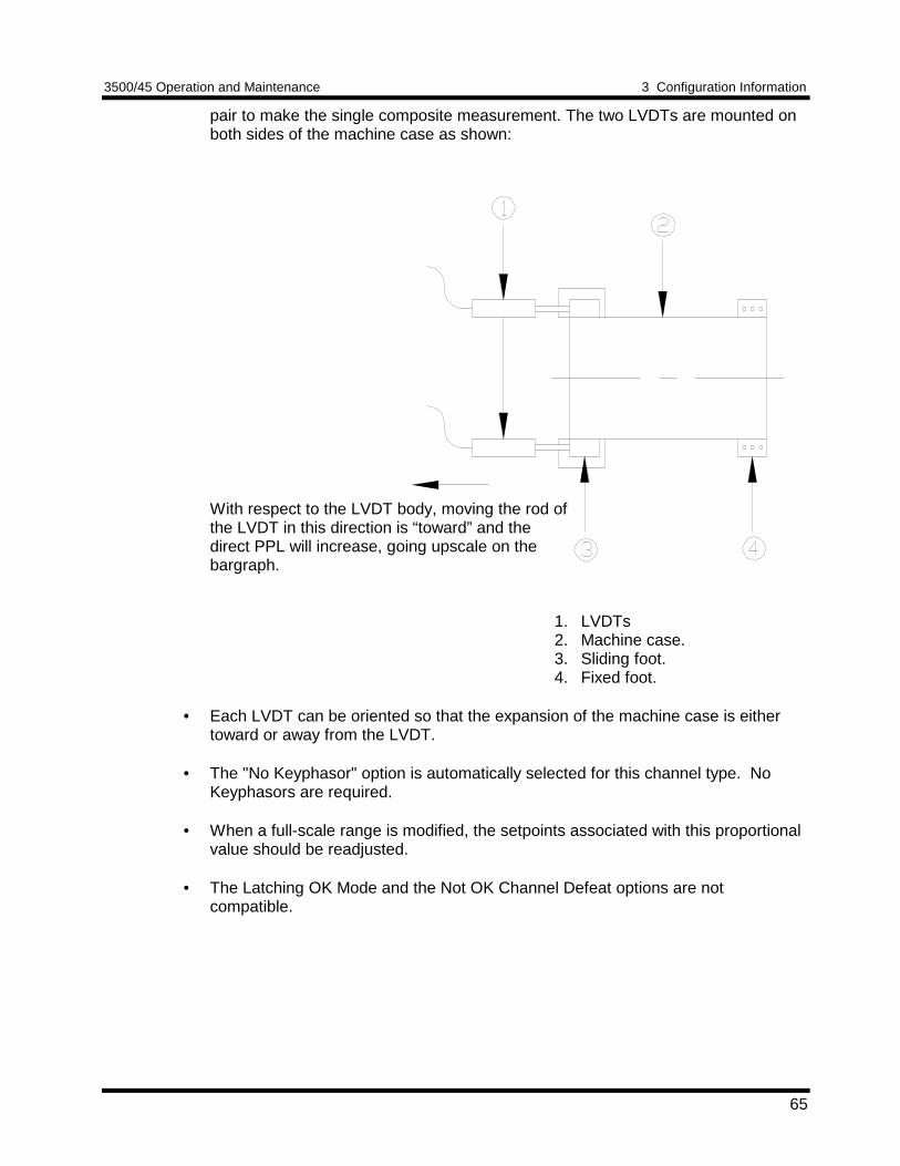
3500/45 Operation and Maintenance 3 Configuration Information
65
pair to make the single composite measurement. The two LVDTs are mounted onboth sides of the machine case as shown:
With respect to the LVDT body, moving the rod ofthe LVDT in this direction is “toward” and thedirect PPL will increase, going upscale on thebargraph.
1. LVDTs2. Machine case.3. Sliding foot.4. Fixed foot.
• Each LVDT can be oriented so that the expansion of the machine case is eithertoward or away from the LVDT.
• The "No Keyphasor" option is automatically selected for this channel type. NoKeyphasors are required.
• When a full-scale range is modified, the setpoints associated with this proportionalvalue should be readjusted.
• The Latching OK Mode and the Not OK Channel Defeat options are notcompatible.
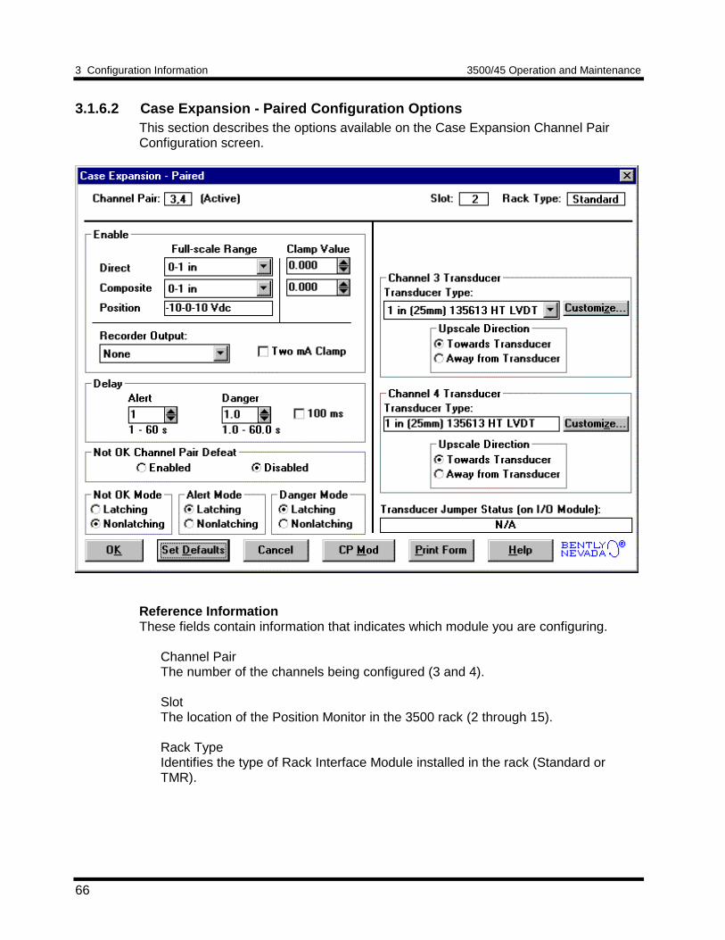
3 Configuration Information 3500/45 Operation and Maintenance
66
3.1.6.2 Case Expansion - Paired Configuration OptionsThis section describes the options available on the Case Expansion Channel PairConfiguration screen.
Reference InformationThese fields contain information that indicates which module you are configuring.
Channel PairThe number of the channels being configured (3 and 4).
SlotThe location of the Position Monitor in the 3500 rack (2 through 15).
Rack TypeIdentifies the type of Rack Interface Module installed in the rack (Standard orTMR).
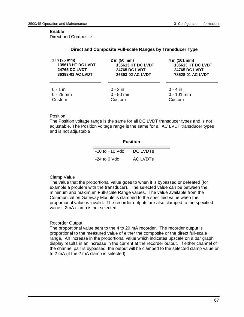
3500/45 Operation and Maintenance 3 Configuration Information
67
EnableDirect and Composite
Direct and Composite Full-scale Ranges by Transducer Type
1 in (25 mm) 135613 HT DC LVDT 24765 DC LVDT 36393-01 AC LVDT
2 in (50 mm) 135613 HT DC LVDT 24765 DC LVDT 36393-02 AC LVDT
4 in (101 mm) 135613 HT DC LVDT 24765 DC LVDT 78628-01 AC LVDT
0 - 1 in0 - 25 mmCustom
0 - 2 in0 - 50 mmCustom
0 - 4 in0 - 101 mmCustom
PositionThe Position voltage range is the same for all DC LVDT transducer types and is notadjustable. The Position voltage range is the same for all AC LVDT transducer typesand is not adjustable
Position
-10 to +10 Vdc DC LVDTs
-24 to 0 Vdc AC LVDTs
Clamp ValueThe value that the proportional value goes to when it is bypassed or defeated (forexample a problem with the transducer). The selected value can be between theminimum and maximum Full-scale Range values. The value available from theCommunication Gateway Module is clamped to the specified value when theproportional value is invalid. The recorder outputs are also clamped to the specifiedvalue if 2mA clamp is not selected.
Recorder OutputThe proportional value sent to the 4 to 20 mA recorder. The recorder output isproportional to the measured value of either the composite or the direct full-scalerange. An increase in the proportional value which indicates upscale on a bar graphdisplay results in an increase in the current at the recorder output. If either channel ofthe channel pair is bypassed, the output will be clamped to the selected clamp value orto 2 mA (if the 2 mA clamp is selected).
3 Configuration Information 3500/45 Operation and Maintenance
68
DelayThe time which a proportional value must remain at or above an over alarm levelbefore an alarm is declared as active.
AlertFirst level alarm that occurs when the proportional value exceeds the selectedAlert/Alarm 1 setpoint. This setpoint can be set on the Setpoint screen. The Alerttime delay is always set at one second intervals (from 1 to 60) for all availableproportional values.
DangerSecond level alarm that occurs when the proportional value exceeds the selectedDanger/Alarm 2 setpoint. This setpoint can be set on the Setpoint screen.
100 ms optionThe 100 ms (typical) option applies to the Danger time delay only and has thefollowing results:
If the 100 ms option is off ():• The Danger time delay can be set at one second intervals (from 1 through
60).• The Danger time delay can be set for any two available proportional values.
If the 100 ms option is on ():• The Danger time delay is set to 100 ms.
Not OK Channel Pair DefeatWhen this option is disabled the Case Expansion channel pair will drive an alarm evenwhen the channel pair is in the not OK state if the alarm setpoint has been exceededfor the delay time. When enabled this option will inhibit alarming if the channel pairgoes to a not OK condition. In addition, when this option is enabled, the not OKcondition must be removed for 10 seconds before monitoring resumes.
OK Mode
LatchingIf the channel pair is configured for Latching OK, once the channel pair has gonenot OK the status stays not OK until the channel is in an OK condition and a resetis issued. Reset a latched not OK by using one of the following methods:• the reset switch on the front of the Rack Interface Module• the external contact closure on the Rack Interface I/O Module• the Reset button in the Operator Display Software• the reset command through the Communication Gateway Module
NonlatchingThe OK status of the channel pair will track the defined OK status of thetransducer.
3500/45 Operation and Maintenance 3 Configuration Information
69
Alarm Mode
LatchingOnce an alarm is active, it will remain active even after the proportional value dropsbelow the configured setpoint level. The channel will remain in alarm until it isreset using one of the following methods:• the reset switch on the front of the Rack Interface Module• the contact on the Rack Interface I/O Module• the Reset button in the Operator Display Software• the reset command through the Communication Gateway Module
NonlatchingWhen an alarm is active, it will go inactive as soon as the proportional value dropsbelow the configured setpoint level.
Alert should be the first level alarm that occurs when the proportional valueexceeds the selected value. Danger should be the second level alarm that occurswhen the proportional value exceeds the selected value. The Alert and Dangervalues are set on the Setpoint screen.
ChannelTransducer TypeThe following transducer types are available:
1 in (25 mm) 135613 HT DC LVDT2 in (50 mm) 135613 HT DC LVDT4 in (101mm) 135613 HT DC LVDT1 in (25 mm) 24765 DC LVDT2 in (50 mm) 24765 DC LVDT4 in (101mm) 24765 DC LVDT1 in (25 mm) 36393-01 AC LVDT2 in (50 mm) 36393-02 AC LVDT4 in (101mm) 78628-01 AC LVDTNonstandard
Customize buttonUsed to adjust the Full Upscale/Downscale voltages of the DC LVDT or to adjustthe Channel Sensitivity of the AC LVDT. If Nonstandard is selected DC LVDT orAC LVDT may be selected as the transducer type. The Full Upscale/Downscalevoltage and the OK Limits can be adjusted with the nonstandard DC LVDT. TheChannel Sensitivity and the OK Limits can be adjusted with the nonstandard ACLVDT. There must be at least 2 volts between the Upper and Lower OK Limits.
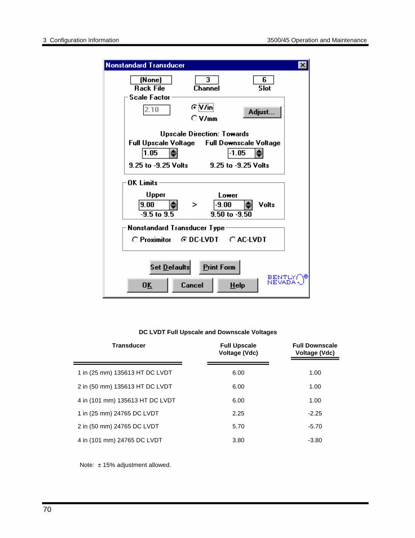
3 Configuration Information 3500/45 Operation and Maintenance
70
DC LVDT Full Upscale and Downscale Voltages
Transducer Full UpscaleVoltage (Vdc)
Full DownscaleVoltage (Vdc)
1 in (25 mm) 135613 HT DC LVDT
2 in (50 mm) 135613 HT DC LVDT
4 in (101 mm) 135613 HT DC LVDT
6.00
6.00
6.00
1.00
1.00
1.00
1 in (25 mm) 24765 DC LVDT 2.25 -2.25
2 in (50 mm) 24765 DC LVDT
4 in (101 mm) 24765 DC LVDT
5.70
3.80
-5.70
-3.80
Note: ± 15% adjustment allowed.
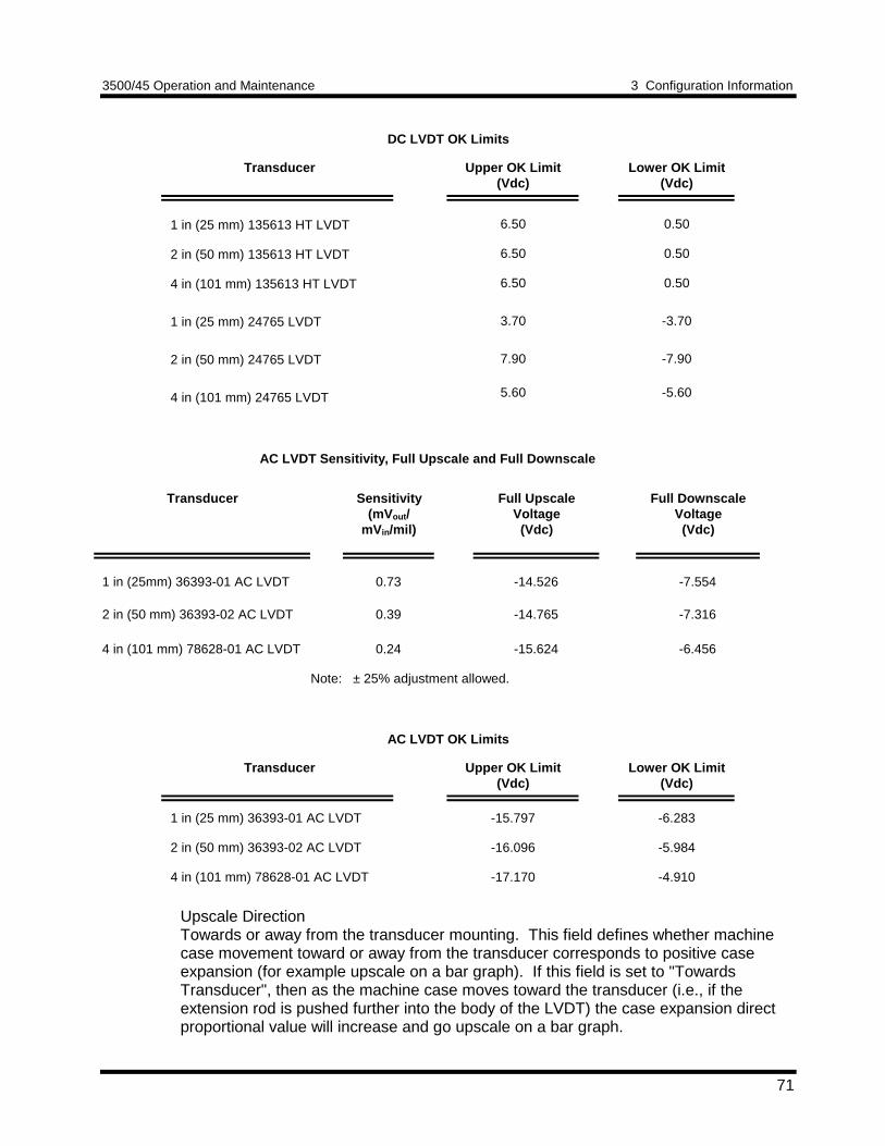
3500/45 Operation and Maintenance 3 Configuration Information
71
DC LVDT OK Limits
Transducer Upper OK Limit(Vdc)
Lower OK Limit(Vdc)
1 in (25 mm) 135613 HT LVDT
2 in (50 mm) 135613 HT LVDT
4 in (101 mm) 135613 HT LVDT
1 in (25 mm) 24765 LVDT
2 in (50 mm) 24765 LVDT
4 in (101 mm) 24765 LVDT
6.50
6.50
6.50
3.70
7.90
5.60
0.50
0.50
0.50
-3.70
-7.90
-5.60
AC LVDT Sensitivity, Full Upscale and Full Downscale
Transducer Sensitivity(mVout /
mVin/mil)
Full UpscaleVoltage
(Vdc)
Full DownscaleVoltage
(Vdc)
1 in (25mm) 36393-01 AC LVDT 0.73 -14.526 -7.554
2 in (50 mm) 36393-02 AC LVDT 0.39 -14.765 -7.316
4 in (101 mm) 78628-01 AC LVDT 0.24 -15.624 -6.456
Note: ± 25% adjustment allowed.
AC LVDT OK Limits
Transducer Upper OK Limit(Vdc)
Lower OK Limit(Vdc)
1 in (25 mm) 36393-01 AC LVDT
2 in (50 mm) 36393-02 AC LVDT
4 in (101 mm) 78628-01 AC LVDT
-15.797
-16.096
-17.170
-6.283
-5.984
-4.910
Upscale DirectionTowards or away from the transducer mounting. This field defines whether machinecase movement toward or away from the transducer corresponds to positive caseexpansion (for example upscale on a bar graph). If this field is set to "TowardsTransducer", then as the machine case moves toward the transducer (i.e., if theextension rod is pushed further into the body of the LVDT) the case expansion directproportional value will increase and go upscale on a bar graph.
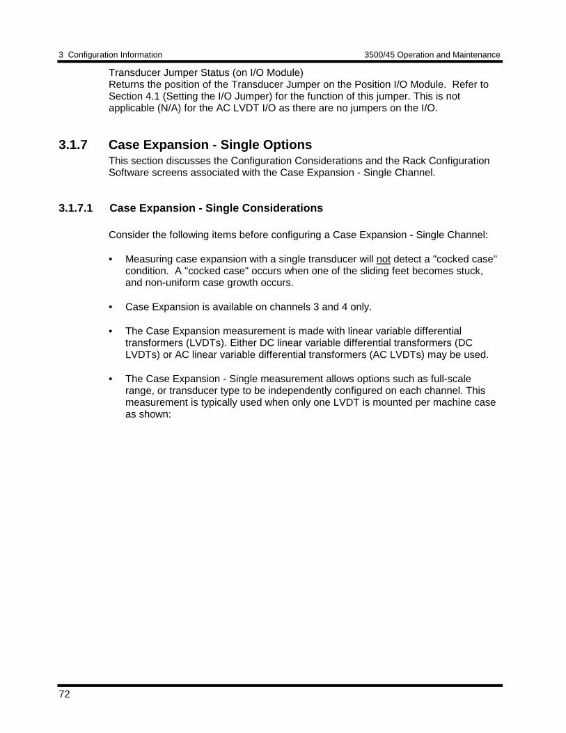
3 Configuration Information 3500/45 Operation and Maintenance
72
Transducer Jumper Status (on I/O Module)Returns the position of the Transducer Jumper on the Position I/O Module. Refer toSection 4.1 (Setting the I/O Jumper) for the function of this jumper. This is notapplicable (N/A) for the AC LVDT I/O as there are no jumpers on the I/O.
3.1.7 Case Expansion - Single OptionsThis section discusses the Configuration Considerations and the Rack ConfigurationSoftware screens associated with the Case Expansion - Single Channel.
3.1.7.1 Case Expansion - Single Considerations
Consider the following items before configuring a Case Expansion - Single Channel:
• Measuring case expansion with a single transducer will not detect a "cocked case"condition. A "cocked case" occurs when one of the sliding feet becomes stuck,and non-uniform case growth occurs.
• Case Expansion is available on channels 3 and 4 only.
• The Case Expansion measurement is made with linear variable differentialtransformers (LVDTs). Either DC linear variable differential transformers (DCLVDTs) or AC linear variable differential transformers (AC LVDTs) may be used.
• The Case Expansion - Single measurement allows options such as full-scalerange, or transducer type to be independently configured on each channel. Thismeasurement is typically used when only one LVDT is mounted per machine caseas shown:
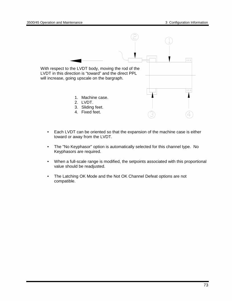
3500/45 Operation and Maintenance 3 Configuration Information
73
With respect to the LVDT body, moving the rod of theLVDT in this direction is “toward” and the direct PPLwill increase, going upscale on the bargraph.
1. Machine case.2. LVDT.3. Sliding feet.4. Fixed feet.
• Each LVDT can be oriented so that the expansion of the machine case is eithertoward or away from the LVDT.
• The "No Keyphasor" option is automatically selected for this channel type. NoKeyphasors are required.
• When a full-scale range is modified, the setpoints associated with this proportionalvalue should be readjusted.
• The Latching OK Mode and the Not OK Channel Defeat options are notcompatible.
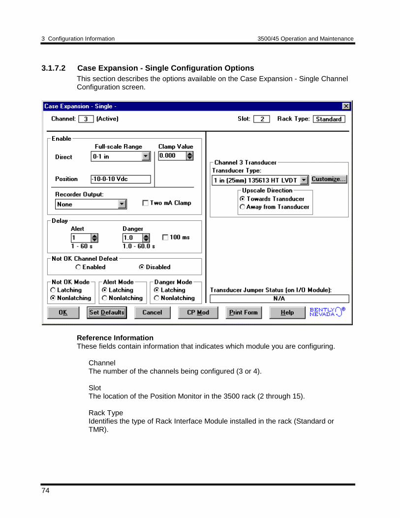
3 Configuration Information 3500/45 Operation and Maintenance
74
3.1.7.2 Case Expansion - Single Configuration OptionsThis section describes the options available on the Case Expansion - Single ChannelConfiguration screen.
Reference InformationThese fields contain information that indicates which module you are configuring.
ChannelThe number of the channels being configured (3 or 4).
SlotThe location of the Position Monitor in the 3500 rack (2 through 15).
Rack TypeIdentifies the type of Rack Interface Module installed in the rack (Standard orTMR).
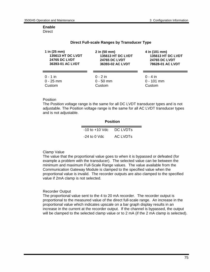
3500/45 Operation and Maintenance 3 Configuration Information
75
EnableDirect
Direct Full-scale Ranges by Transducer Type
1 in (25 mm) 135613 HT DC LVDT 24765 DC LVDT 36393-01 AC LVDT
2 in (50 mm) 135613 HT DC LVDT 24765 DC LVDT 36393-02 AC LVDT
4 in (101 mm) 135613 HT DC LVDT 24765 DC LVDT 78628-01 AC LVDT
0 - 1 in0 - 25 mmCustom
0 - 2 in0 - 50 mmCustom
0 - 4 in0 - 101 mmCustom
PositionThe Position voltage range is the same for all DC LVDT transducer types and is notadjustable. The Position voltage range is the same for all AC LVDT transducer typesand is not adjustable.
Position
-10 to +10 Vdc DC LVDTs
-24 to 0 Vdc AC LVDTs
Clamp ValueThe value that the proportional value goes to when it is bypassed or defeated (forexample a problem with the transducer). The selected value can be between theminimum and maximum Full-Scale Range values. The value available from theCommunication Gateway Module is clamped to the specified value when theproportional value is invalid. The recorder outputs are also clamped to the specifiedvalue if 2mA clamp is not selected.
Recorder OutputThe proportional value sent to the 4 to 20 mA recorder. The recorder output isproportional to the measured value of the direct full-scale range. An increase in theproportional value which indicates upscale on a bar graph display results in anincrease in the current at the recorder output. If the channel is bypassed, the outputwill be clamped to the selected clamp value or to 2 mA (if the 2 mA clamp is selected).
3 Configuration Information 3500/45 Operation and Maintenance
76
DelayThe time which a proportional value must remain at or above an over alarm levelbefore an alarm is declared as active.
AlertFirst level alarm that occurs when the proportional value exceeds the selectedAlert/Alarm 1 setpoint. This setpoint can be set on the Setpoint screen. The Alerttime delay is always set at one second intervals (from 1 to 60) for all availableproportional values.
DangerSecond level alarm that occurs when the proportional value exceeds the selectedDanger/Alarm 2 setpoint. This setpoint can be set on the Setpoint screen.
100 ms optionThe 100 ms (typical) option applies to the Danger time delay only and has thefollowing results:
If the 100 ms option is off ():• The Danger time delay can be set at one second intervals (from 1 through
60).• The Danger time delay can be set for the Direct proportional value.
If the 100 ms option is on ():• The Danger time delay is set to 100 ms.• The Danger time delay can only be set for the Direct proportional value.
Not OK Channel DefeatWhen this option is disabled the Case Expansion channel will drive an alarm evenwhen the channel is in the not OK state if the alarm setpoint has been exceeded forthe delay time. When enabled this option will inhibit alarming if the channel goes to anot OK condition. In addition, when this option is enabled, the not OK condition mustbe removed for 10 seconds before monitoring resumes.
OK Mode
LatchingIf the channel is configured for Latching OK, once the channel has gone not OKthe status stays not OK until the channel is in an OK condition and a reset isissued. Reset a latched not OK by using one of the following methods:• the reset switch on the front of the Rack Interface Module• the external contact closure on the Rack Interface I/O Module• the Reset button in the Operator Display Software• the reset command through the Communication Gateway Module
NonlatchingThe OK status of the channel will track the defined OK status of the transducer.
3500/45 Operation and Maintenance 3 Configuration Information
77
Alarm Mode
LatchingOnce an alarm is active, it will remain active even after the proportional value dropsbelow the configured setpoint level. The channel will remain in alarm until it isreset using one of the following methods:• the reset switch on the front of the Rack Interface Module• the contact on the Rack Interface I/O Module• the Reset button in the Operator Display Software• the reset command through the Communication Gateway Module
NonlatchingWhen an alarm is active, it will go inactive as soon as the proportional value dropsbelow the configured setpoint level.
Alert should be the first level alarm that occurs when the proportional valueexceeds the selected value. Danger should be the second level alarm that occurswhen the proportional value exceeds the selected value. The Alert and Dangervalues are set on the Setpoint screen.
ChannelTransducer TypeThe following transducer types are available:
1 in (25 mm) 135613 HT LVDT2 in (50 mm) 135613 HT LVDT4 in (101mm) 135613 HT LVDT1 in (25 mm) 24765 LVDT2 in (50 mm) 24765 LVDT4 in (101mm) 24765 LVDT1 in (25 mm) 36393-01 AC LVDT2 in (50 mm) 36393-02 AC LVDT4 in (101mm) 78628-01 AC LVDTNonstandard
Customize buttonUsed to adjust the Full Upscale/Downscale voltages of the DC LVDT or to adjustthe Sensitivity of the AC LVDT. If Nonstandard is selected DC LVDT or AC LVDTmay be selected as the transducer type. The Full Upscale/Downscale voltage andthe OK Limits can be adjusted with the nonstandard DC LVDT. The ChannelSensitivity and the OK Limits can be adjusted with the nonstandard AC LVDT.There must be at least 2 volts between the Upper and Lower OK Limits.
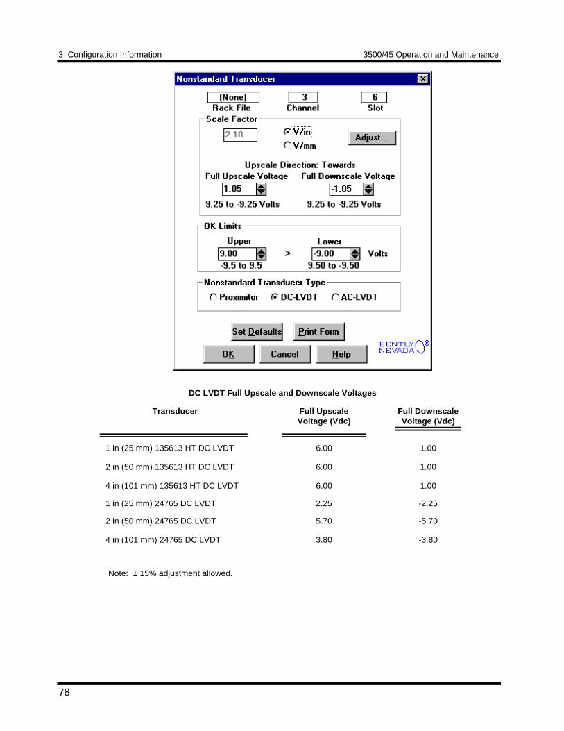
3 Configuration Information 3500/45 Operation and Maintenance
78
DC LVDT Full Upscale and Downscale Voltages
Transducer Full UpscaleVoltage (Vdc)
Full DownscaleVoltage (Vdc)
1 in (25 mm) 135613 HT DC LVDT
2 in (50 mm) 135613 HT DC LVDT
4 in (101 mm) 135613 HT DC LVDT
6.00
6.00
6.00
1.00
1.00
1.00
1 in (25 mm) 24765 DC LVDT 2.25 -2.25
2 in (50 mm) 24765 DC LVDT
4 in (101 mm) 24765 DC LVDT
5.70
3.80
-5.70
-3.80
Note: ± 15% adjustment allowed.
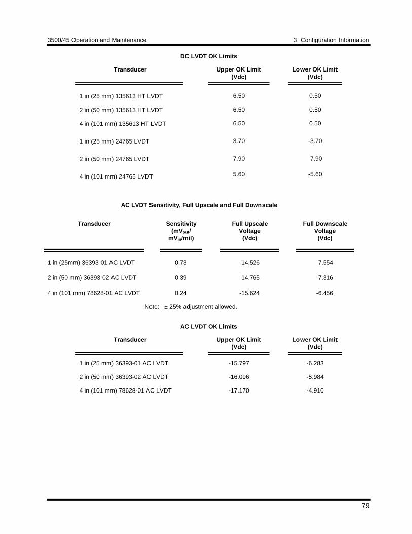
3500/45 Operation and Maintenance 3 Configuration Information
79
DC LVDT OK Limits
Transducer Upper OK Limit(Vdc)
Lower OK Limit(Vdc)
1 in (25 mm) 135613 HT LVDT
2 in (50 mm) 135613 HT LVDT
4 in (101 mm) 135613 HT LVDT
1 in (25 mm) 24765 LVDT
2 in (50 mm) 24765 LVDT
4 in (101 mm) 24765 LVDT
6.50
6.50
6.50
3.70
7.90
5.60
0.50
0.50
0.50
-3.70
-7.90
-5.60
AC LVDT Sensitivity, Full Upscale and Full Downscale
Transducer Sensitivity(mVout /
mVin/mil)
Full UpscaleVoltage
(Vdc)
Full DownscaleVoltage
(Vdc)
1 in (25mm) 36393-01 AC LVDT 0.73 -14.526 -7.554
2 in (50 mm) 36393-02 AC LVDT 0.39 -14.765 -7.316
4 in (101 mm) 78628-01 AC LVDT 0.24 -15.624 -6.456
Note: ± 25% adjustment allowed.
AC LVDT OK Limits
Transducer Upper OK Limit(Vdc)
Lower OK Limit(Vdc)
1 in (25 mm) 36393-01 AC LVDT
2 in (50 mm) 36393-02 AC LVDT
4 in (101 mm) 78628-01 AC LVDT
-15.797
-16.096
-17.170
-6.283
-5.984
-4.910
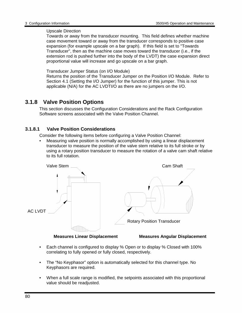
3 Configuration Information 3500/45 Operation and Maintenance
80
Upscale DirectionTowards or away from the transducer mounting. This field defines whether machinecase movement toward or away from the transducer corresponds to positive caseexpansion (for example upscale on a bar graph). If this field is set to "TowardsTransducer", then as the machine case moves toward the transducer (i.e., if theextension rod is pushed further into the body of the LVDT) the case expansion directproportional value will increase and go upscale on a bar graph.
Transducer Jumper Status (on I/O Module)Returns the position of the Transducer Jumper on the Position I/O Module. Refer toSection 4.1 (Setting the I/O Jumper) for the function of this jumper. This is notapplicable (N/A) for the AC LVDTI/O as there are no jumpers on the I/O.
3.1.8 Valve Position OptionsThis section discusses the Configuration Considerations and the Rack ConfigurationSoftware screens associated with the Valve Position Channel.
3.1.8.1 Valve Position ConsiderationsConsider the following items before configuring a Valve Position Channel:• Measuring valve position is normally accomplished by using a linear displacement
transducer to measure the position of the valve stem relative to its full stroke or byusing a rotary position transducer to measure the rotation of a valve cam shaft relativeto its full rotation.
Valve Stem Cam Shaft
AC LVDT
Rotary Position Transducer
Measures Linear Displacement Measures Angular Displacement
• Each channel is configured to display % Open or to display % Closed with 100%correlating to fully opened or fully closed, respectively.
• The “No Keyphasor” option is automatically selected for this channel type. NoKeyphasors are required.
• When a full scale range is modified, the setpoints associated with this proportionalvalue should be readjusted.
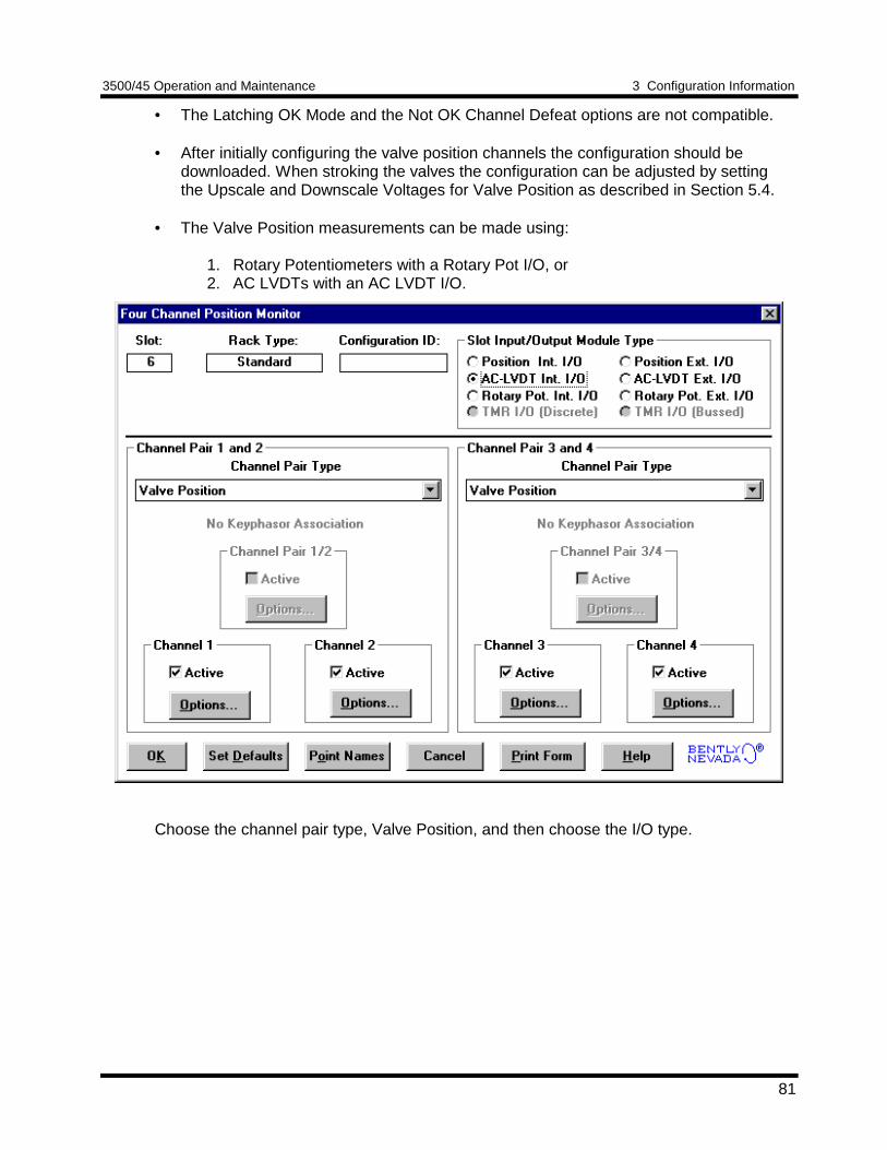
3500/45 Operation and Maintenance 3 Configuration Information
81
• The Latching OK Mode and the Not OK Channel Defeat options are not compatible.
• After initially configuring the valve position channels the configuration should bedownloaded. When stroking the valves the configuration can be adjusted by settingthe Upscale and Downscale Voltages for Valve Position as described in Section 5.4.
• The Valve Position measurements can be made using:
1. Rotary Potentiometers with a Rotary Pot I/O, or2. AC LVDTs with an AC LVDT I/O.
Choose the channel pair type, Valve Position, and then choose the I/O type.
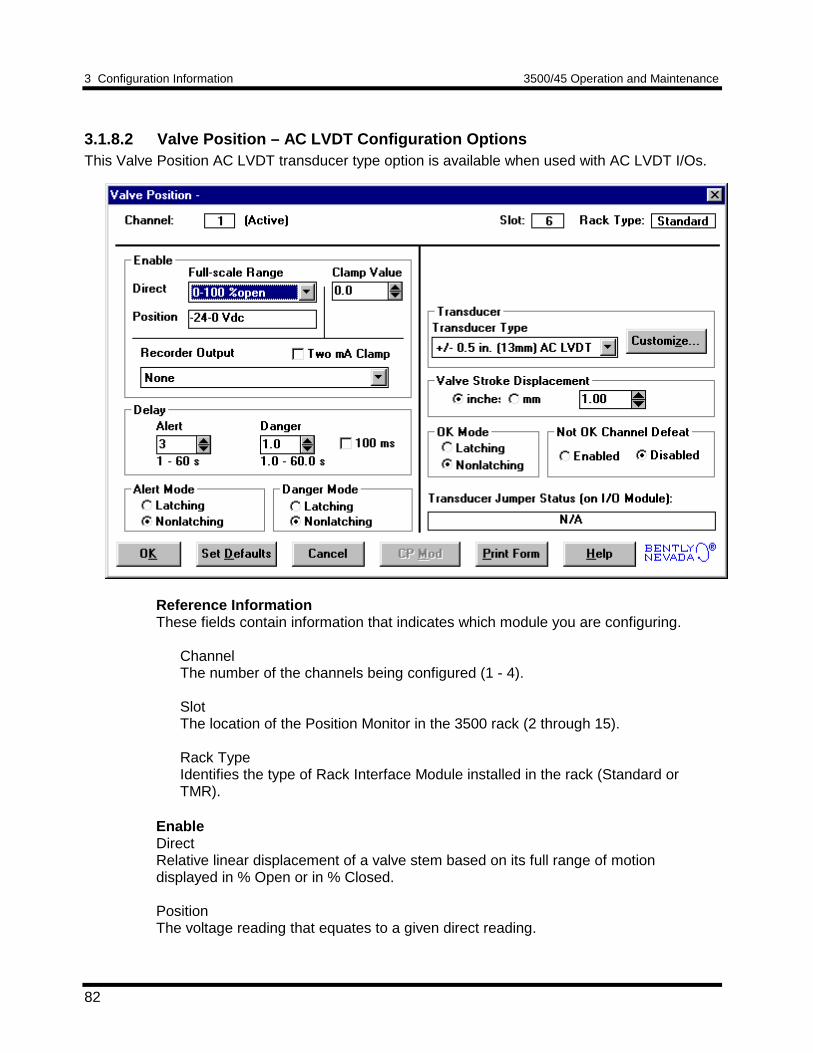
3 Configuration Information 3500/45 Operation and Maintenance
82
3.1.8.2 Valve Position – AC LVDT Configuration OptionsThis Valve Position AC LVDT transducer type option is available when used with AC LVDT I/Os.
Reference InformationThese fields contain information that indicates which module you are configuring.
ChannelThe number of the channels being configured (1 - 4).
SlotThe location of the Position Monitor in the 3500 rack (2 through 15).
Rack TypeIdentifies the type of Rack Interface Module installed in the rack (Standard orTMR).
EnableDirectRelative linear displacement of a valve stem based on its full range of motiondisplayed in % Open or in % Closed.
PositionThe voltage reading that equates to a given direct reading.
3500/45 Operation and Maintenance 3 Configuration Information
83
Clamp ValueThe value that the proportional value goes to when it is bypassed or defeated (forexample a problem with the transducer). The selected value can be between 0 and100%. The value available from the Communication Gateway Module is clamped tothe specified value when the proportional value is invalid. The recorder outputs arealso clamped to the specified value if 2mA clamp is not selected.
Recorder OutputThe proportional value sent to the 4 to 20mA recorder. The recorder output isproportional to the measured value of the direct full-scale range. An increase in theproportional value which indicates upscale on a bar graph display results in anincrease in the current at the recorder output. If the channel is bypassed, the outputwill be clamped to the selected clamp value or to 2mA (if the 2mA clamp is selected).
DelayThe time which a proportional value must remain at or above an over alarm levelbefore an alarm is declared as active.
AlertFirst level alarm that occurs when the proportional value exceeds the selectedAlert/Alarm 1 setpoint. This setpoint can be set on the Setpoint screen. The Alerttime delay is always set at one second intervals (from 1 to 60) for all availableproportional values.
DangerSecond level alarm that occurs when the proportional value exceeds the selectedDanger/Alarm 2 setpoint. This setpoint can be set on the Setpoint screen.
100 ms optionThe 100 ms (typical) option applies to the Danger time delay only and has thefollowing results:
If the 100 ms option is off ():• The Danger time delay can be set at one second intervals (from 1 through
60).• The Danger time delay can be set for the Direct proportional value.
If the 100 ms option is on ():• The Danger time delay is set to 100 ms.• The Danger time delay can only be set for the Direct proportional value.
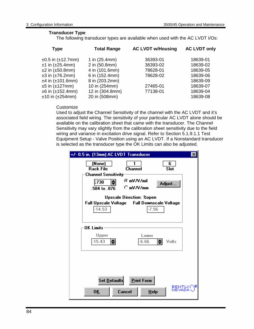
3 Configuration Information 3500/45 Operation and Maintenance
84
Transducer TypeThe following transducer types are available when used with the AC LVDT I/Os:
Type Total Range AC LVDT w/Housing AC LVDT only
±0.5 in (±12.7mm) 1 in (25.4mm) 36393-01 18639-01±1 in (±25.4mm) 2 in (50.8mm) 36393-02 18639-02±2 in (±50.8mm) 4 in (101.6mm) 78628-01 18639-05±3 in (±76.2mm) 6 in (152.4mm) 78628-02 18639-06±4 in (±101.6mm) 8 in (203.2mm) 18639-09±5 in (±127mm) 10 in (254mm) 27465-01 18639-07±6 in (±152.4mm) 12 in (304.8mm) 77138-01 18639-04±10 in (±254mm) 20 in (508mm) 18639-08
CustomizeUsed to adjust the Channel Sensitivity of the channel with the AC LVDT and it’sassociated field wiring. The sensitivity of your particular AC LVDT alone should beavailable on the calibration sheet that came with the transducer. The ChannelSensitivity may vary slightly from the calibration sheet sensitivity due to the fieldwiring and variance in excitation drive signal. Refer to Section 5.1.9.1.1 TestEquipment Setup - Valve Position using an AC LVDT. If a Nonstandard transduceris selected as the transducer type the OK Limits can also be adjusted.
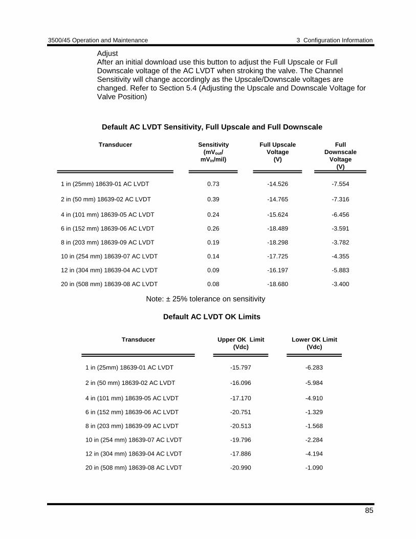
3500/45 Operation and Maintenance 3 Configuration Information
85
AdjustAfter an initial download use this button to adjust the Full Upscale or FullDownscale voltage of the AC LVDT when stroking the valve. The ChannelSensitivity will change accordingly as the Upscale/Downscale voltages arechanged. Refer to Section 5.4 (Adjusting the Upscale and Downscale Voltage forValve Position)
Default AC LVDT Sensitivity, Full Upscale and Full Downscale
Transducer Sensitivity(mVout /
mVin/mil)
Full UpscaleVoltage
(V)
FullDownscale
Voltage(V)
1 in (25mm) 18639-01 AC LVDT 0.73 -14.526 -7.554
2 in (50 mm) 18639-02 AC LVDT 0.39 -14.765 -7.316
4 in (101 mm) 18639-05 AC LVDT 0.24 -15.624 -6.456
6 in (152 mm) 18639-06 AC LVDT 0.26 -18.489 -3.591
8 in (203 mm) 18639-09 AC LVDT 0.19 -18.298 -3.782
10 in (254 mm) 18639-07 AC LVDT 0.14 -17.725 -4.355
12 in (304 mm) 18639-04 AC LVDT 0.09 -16.197 -5.883
20 in (508 mm) 18639-08 AC LVDT 0.08 -18.680 -3.400
Note: ± 25% tolerance on sensitivity
Default AC LVDT OK Limits
Transducer Upper OK Limit(Vdc)
Lower OK Limit(Vdc)
1 in (25mm) 18639-01 AC LVDT -15.797 -6.283
2 in (50 mm) 18639-02 AC LVDT -16.096 -5.984
4 in (101 mm) 18639-05 AC LVDT -17.170 -4.910
6 in (152 mm) 18639-06 AC LVDT -20.751 -1.329
8 in (203 mm) 18639-09 AC LVDT -20.513 -1.568
10 in (254 mm) 18639-07 AC LVDT -19.796 -2.284
12 in (304 mm) 18639-04 AC LVDT -17.886 -4.194
20 in (508 mm) 18639-08 AC LVDT -20.990 -1.090
3 Configuration Information 3500/45 Operation and Maintenance
86
Valve Stroke DisplacementUsed to set the actual displacement of the valve stem (stroke length). The strokelength will correlate to 0 to 100% open or closed. The stroke length can be as largeas the transducer range or as small as ½ the transducer range. For example, forthe +/-2” AC LVDT you could set the stroke length anywhere from 2 inches to 4inches.
Alarm ModeLatchingOnce an alarm is active, it will remain active even after the proportional value dropsbelow the configured setpoint level. The channel will remain in alarm until it isreset using one of the following methods:• the reset switch on the front of the Rack Interface Module• the contact on the Rack Interface I/O Module• the Reset button in the Operator Display Software• the reset command through the Communication Gateway Module
NonlatchingWhen an alarm is active, it will go inactive as soon as the proportional value dropsbelow the configured setpoint level.
Alert should be the first level alarm that occurs when the proportional valueexceeds the selected value. Danger should be the second level alarm that occurswhen the proportional value exceeds the selected value. The Alert and Dangervalues are set on the Setpoint screen.
OK ModeLatchingIf the channel is configured for Latching OK, once the channel has gone not OKthe status stays not OK until the channel is in an OK condition and a reset isissued. Reset a latched not OK by using one of the following methods:• the reset switch on the front of the Rack Interface Module• the external contact closure on the Rack Interface I/O Module• the Reset button in the Operator Display Software• the reset command through the Communication Gateway Module
NonlatchingThe OK status of the channel will track the defined OK status of the transducer.
Not OK Channel DefeatWhen this option is disabled the Valve Position channel will drive an alarm even whenthe channel is in the not OK state if the alarm setpoint has been exceeded for thedelay time. When enabled this option will inhibit alarming if the channel goes to a notOK condition. In addition, when this option is enabled, the not OK condition must beremoved for 10 seconds before monitoring resumes.
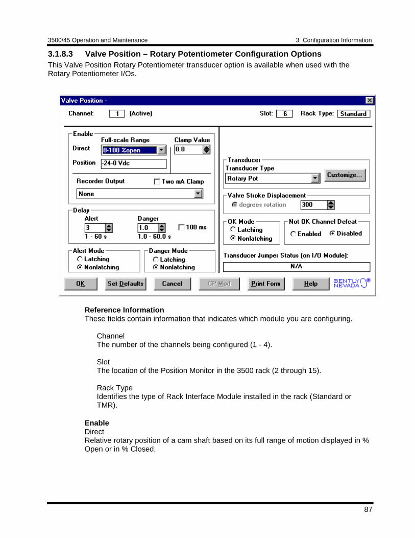
3500/45 Operation and Maintenance 3 Configuration Information
87
3.1.8.3 Valve Position – Rotary Potentiometer Configuration OptionsThis Valve Position Rotary Potentiometer transducer option is available when used with theRotary Potentiometer I/Os.
Reference InformationThese fields contain information that indicates which module you are configuring.
ChannelThe number of the channels being configured (1 - 4).
SlotThe location of the Position Monitor in the 3500 rack (2 through 15).
Rack TypeIdentifies the type of Rack Interface Module installed in the rack (Standard orTMR).
EnableDirectRelative rotary position of a cam shaft based on its full range of motion displayed in %Open or in % Closed.
3 Configuration Information 3500/45 Operation and Maintenance
88
PositionThe voltage reading that equates to a given direct reading.Clamp ValueThe value that the proportional value goes to when it is bypassed or defeated (forexample a problem with the transducer). The selected value can be between 0 and100%. The value available from the Communication Gateway Module is clamped tothe specified value when the proportional value is invalid. The recorder outputs arealso clamped to the specified value if 2mA clamp is not selected.
Recorder OutputThe proportional value sent to the 4 to 20mA recorder. The recorder output isproportional to the measured value of the direct full-scale range. An increase in theproportional value which indicates upscale on a bar graph display results in anincrease in the current at the recorder output. If the channel is bypassed, the outputwill be clamped to the selected clamp value or to 2mA (if the 2mA clamp is selected).
DelayThe time which a proportional value must remain at or above an over alarm levelbefore an alarm is declared as active.
AlertFirst level alarm that occurs when the proportional value exceeds the selectedAlert/Alarm 1 setpoint. This setpoint can be set on the Setpoint screen. The Alerttime delay is always set at one second intervals (from 1 to 60) for all availableproportional values.
DangerSecond level alarm that occurs when the proportional value exceeds the selectedDanger/Alarm 2 setpoint. This setpoint can be set on the Setpoint screen.
100 ms optionThe 100 ms (typical) option applies to the Danger time delay only and has thefollowing results:
If the 100 ms option is off ():• The Danger time delay can be set at one second intervals (from 1 through
60).• The Danger time delay can be set for the Direct proportional value.
If the 100 ms option is on ():• The Danger time delay is set to 100 ms.• The Danger time delay can only be set for the Direct proportional value.
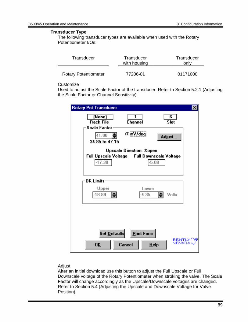
3500/45 Operation and Maintenance 3 Configuration Information
89
Transducer TypeThe following transducer types are available when used with the RotaryPotentiometer I/Os:
Transducer Transducerwith housing
Transduceronly
Rotary Potentiometer 77206-01 01171000
CustomizeUsed to adjust the Scale Factor of the transducer. Refer to Section 5.2.1 (Adjustingthe Scale Factor or Channel Sensitivity).
AdjustAfter an initial download use this button to adjust the Full Upscale or FullDownscale voltage of the Rotary Potentiometer when stroking the valve. The ScaleFactor will change accordingly as the Upscale/Downscale voltages are changed.Refer to Section 5.4 (Adjusting the Upscale and Downscale Voltage for ValvePosition)
3 Configuration Information 3500/45 Operation and Maintenance
90
Upper OK Limit Lower OK LimitRotary Potentiometer -18.893 Vdc -4.348 Vdc
Valve Stroke DisplacementUsed to set the actual full stroke rotational displacement of the cam shaft. Thestroke displacement will correlate to 0 to 100% open or closed. The strokedisplacement can be as large as 300 degrees of rotation or as small as 50 degreesof rotation.
Alarm ModeLatchingOnce an alarm is active, it will remain active even after the proportional value dropsbelow the configured setpoint level. The channel will remain in alarm until it isreset using one of the following methods:• the reset switch on the front of the Rack Interface Module• the contact on the Rack Interface I/O Module• the Reset button in the Operator Display Software• the reset command through the Communication Gateway Module
NonlatchingWhen an alarm is active, it will go inactive as soon as the proportional value dropsbelow the configured setpoint level.
Alert should be the first level alarm that occurs when the proportional valueexceeds the selected value. Danger should be the second level alarm that occurswhen the proportional value exceeds the selected value. The Alert and Dangervalues are set on the Setpoint screen.
OK ModeLatchingIf the channel is configured for Latching OK, once the channel has gone not OKthe status stays not OK until the channel is in an OK condition and a reset isissued. Reset a latched not OK by using one of the following methods:• the reset switch on the front of the Rack Interface Module• the external contact closure on the Rack Interface I/O Module• the Reset button in the Operator Display Software• the reset command through the Communication Gateway Module
NonlatchingThe OK status of the channel will track the defined OK status of the transducer.
Not OK Channel DefeatWhen this option is disabled the Valve Position channel will drive an alarm even whenthe channel is in the not OK state if the alarm setpoint has been exceeded for thedelay time. When enabled this option will inhibit alarming if the channel goes to a notOK condition. In addition, when this option is enabled, the not OK condition must beremoved for 10 seconds before monitoring resumes.
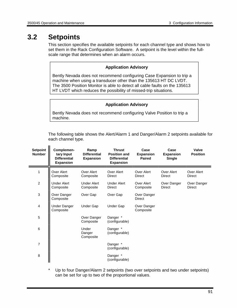
3500/45 Operation and Maintenance 3 Configuration Information
91
3.2 SetpointsThis section specifies the available setpoints for each channel type and shows how toset them in the Rack Configuration Software. A setpoint is the level within the full-scale range that determines when an alarm occurs.
Application Advisory
Bently Nevada does not recommend configuring Case Expansion to trip amachine when using a transducer other than the 135613 HT DC LVDT.The 3500 Position Monitor is able to detect all cable faults on the 135613HT LVDT which reduces the possibility of missed-trip situations.
Application Advisory
Bently Nevada does not recommend configuring Valve Position to trip amachine.
The following table shows the Alert/Alarm 1 and Danger/Alarm 2 setpoints available foreach channel type.
SetpointNumber
Complemen-tary Input
DifferentialExpansion
RampDifferentialExpansion
ThrustPosition andDifferentialExpansion
CaseExpansion
Paired
CaseExpansion
Single
ValvePosition
1 Over AlertComposite
Over AlertComposite
Over AlertDirect
Over AlertDirect
Over AlertDirect
Over AlertDirect
2 Under AlertComposite
Under AlertComposite
Under AlertDirect
Over AlertComposite
Over DangerDirect
Over DangerDirect
3 Over DangerComposite
Over Gap Over Gap Over DangerDirect
4 Under DangerComposite
Under Gap Under Gap Over DangerComposite
5 Over DangerComposite
Danger *(configurable)
6 UnderDangerComposite
Danger *(configurable)
7 Danger *(configurable)
8 Danger *(configurable)
* Up to four Danger/Alarm 2 setpoints (two over setpoints and two under setpoints)can be set for up to two of the proportional values.
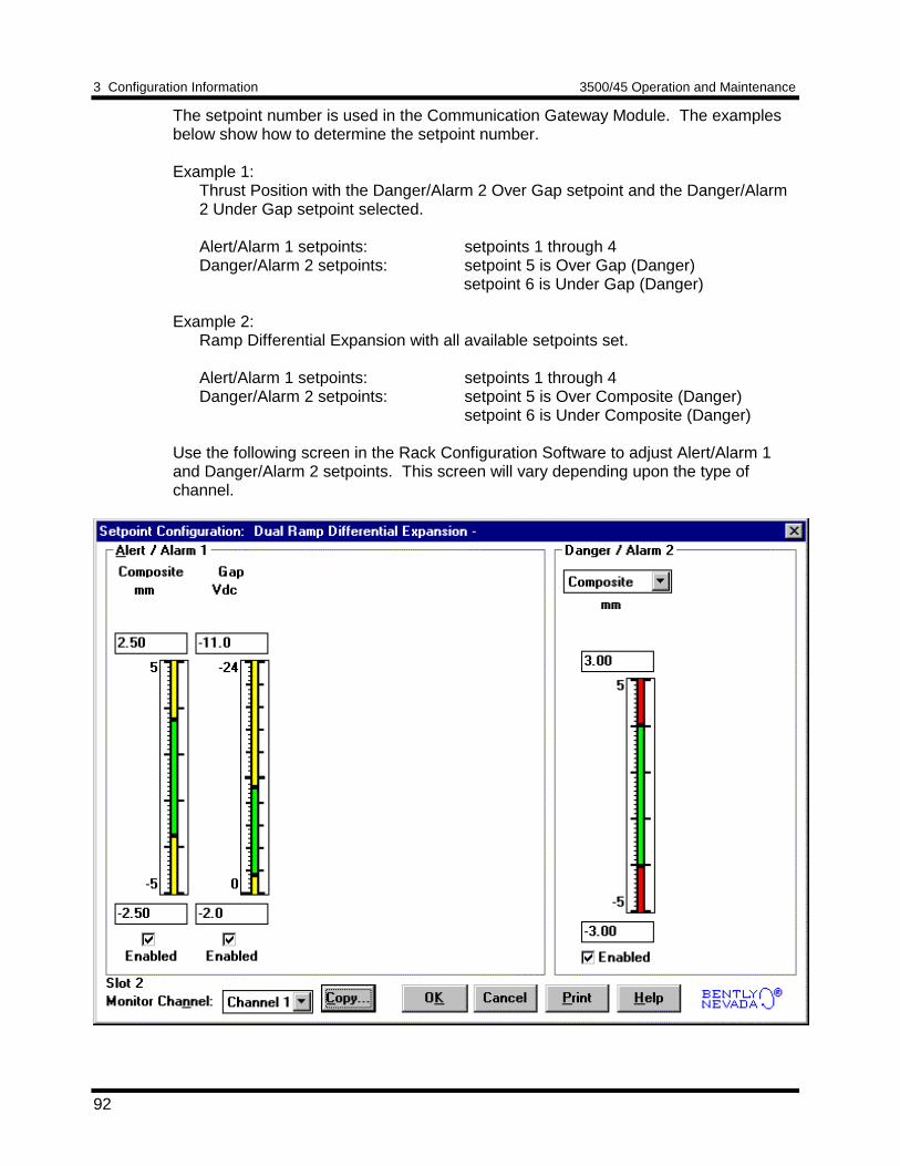
3 Configuration Information 3500/45 Operation and Maintenance
92
The setpoint number is used in the Communication Gateway Module. The examplesbelow show how to determine the setpoint number.
Example 1:Thrust Position with the Danger/Alarm 2 Over Gap setpoint and the Danger/Alarm2 Under Gap setpoint selected.
Alert/Alarm 1 setpoints: setpoints 1 through 4Danger/Alarm 2 setpoints: setpoint 5 is Over Gap (Danger)
setpoint 6 is Under Gap (Danger)
Example 2:Ramp Differential Expansion with all available setpoints set.
Alert/Alarm 1 setpoints: setpoints 1 through 4Danger/Alarm 2 setpoints: setpoint 5 is Over Composite (Danger)
setpoint 6 is Under Composite (Danger)
Use the following screen in the Rack Configuration Software to adjust Alert/Alarm 1and Danger/Alarm 2 setpoints. This screen will vary depending upon the type ofchannel.
3500/45 Operation and Maintenance 3 Configuration Information
93
Notes
1. The setpoint over and under limits can only be placed within the linear rangeof the specified transducer. For Ramp Differential Expansion the setpoint overand under limits may be less than the linear range of the transducerdepending on the ramp angle and full-scale range.
2. For Ramp Differential Expansion, Complementary Input DifferentialExpansion, and Case Expansion - Paired; the setpoints for the compositeproportional value can be set independently on each channel of the channelpair. You must adjust setpoints on both channels of the channel pair.
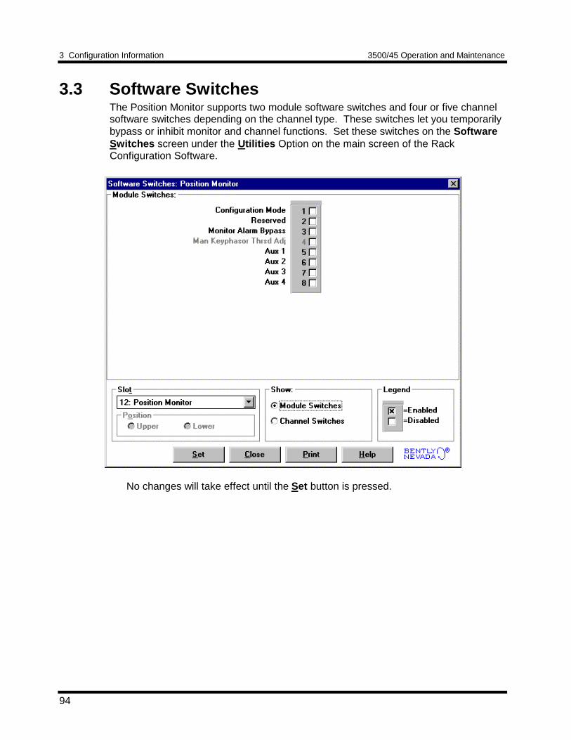
3 Configuration Information 3500/45 Operation and Maintenance
94
3.3 Software SwitchesThe Position Monitor supports two module software switches and four or five channelsoftware switches depending on the channel type. These switches let you temporarilybypass or inhibit monitor and channel functions. Set these switches on the SoftwareSwitches screen under the Utilities Option on the main screen of the RackConfiguration Software.
No changes will take effect until the Set button is pressed.
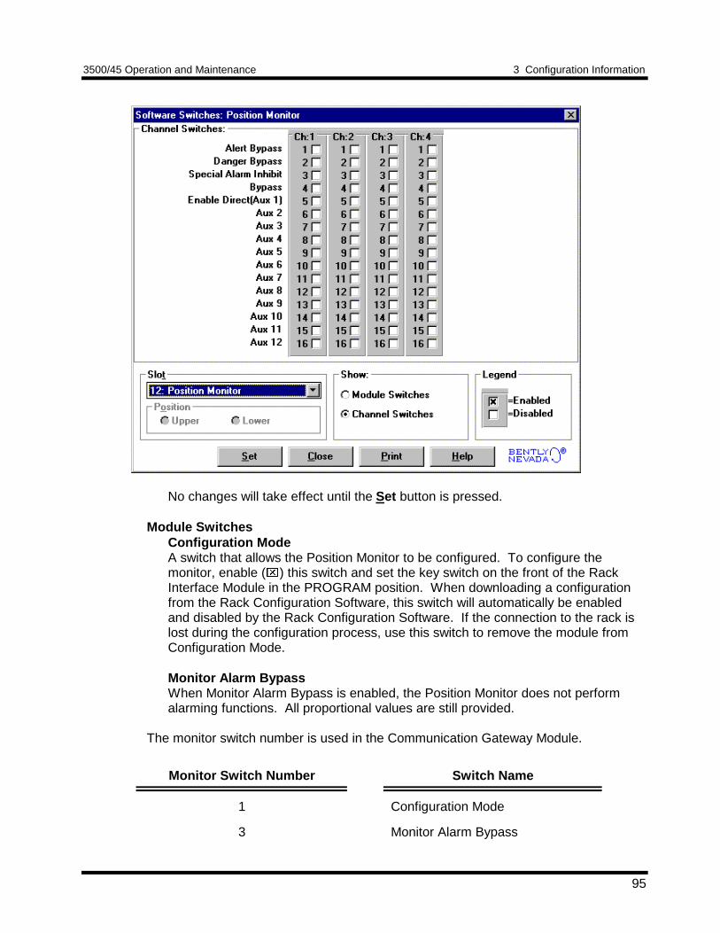
3500/45 Operation and Maintenance 3 Configuration Information
95
No changes will take effect until the Set button is pressed.
Module SwitchesConfiguration ModeA switch that allows the Position Monitor to be configured. To configure themonitor, enable () this switch and set the key switch on the front of the RackInterface Module in the PROGRAM position. When downloading a configurationfrom the Rack Configuration Software, this switch will automatically be enabledand disabled by the Rack Configuration Software. If the connection to the rack islost during the configuration process, use this switch to remove the module fromConfiguration Mode.
Monitor Alarm BypassWhen Monitor Alarm Bypass is enabled, the Position Monitor does not performalarming functions. All proportional values are still provided.
The monitor switch number is used in the Communication Gateway Module.
Monitor Switch Number Switch Name
1 Configuration Mode
3 Monitor Alarm Bypass
3 Configuration Information 3500/45 Operation and Maintenance
96
Channel Switches
NoteSet or reset both channels of the channel pair to fully implement the switchfunction for the following channel types:• Ramp Differential Expansion• Complementary Input Differential Expansion• Case Expansion - Paired
Alert BypassWhen Alert Bypass is enabled, the channel does not perform Alert alarmingfunctions.
Danger BypassWhen Danger Bypass is enabled, the channel does not perform Danger alarmingfunctions.
Special Alarm InhibitWhen Special Alarm Inhibit is enabled, all non-primary Alert alarms are inhibited.
BypassWhen Bypass is enabled, the channel provides no alarming functions and suppliesno proportional values.
NOTEFor Complementary Input Differential Expansion both channels of the channelpair will be Bypassed when the Bypass switch is set on either channel of thechannel pair. As a result, the System Event list will contain entries for bothchannels of the pair.
For Ramp Differential Expansion and Case Expansion - Paired, the ChannelBypass switch will only operate on the assigned channel. However, bypassingone channel will cause the Composite proportional value on the other channelto become invalid. The unbypassed channel will continue to return Gap orPosition and Direct (if enabled).
Enable Direct (Aux 1)A switch which enables the individual channel direct proportional values for RampDifferential Expansion and Complementary Input Differential Expansion. Thesevalues are required for setting zero position voltages, cross over voltages, andverification. When you press the Adjust button for zero position voltage or crossover voltage, the Rack Configuration Software automatically sets this switch andwill automatically reset (disable) the switch prior to downloading configuration. Thisswitch has no effect on other monitor channel types. You can operate the monitorwith the switch enabled or disabled. The Direct proportional value may be usefulfor machinery management information but it is not used for machine protection.
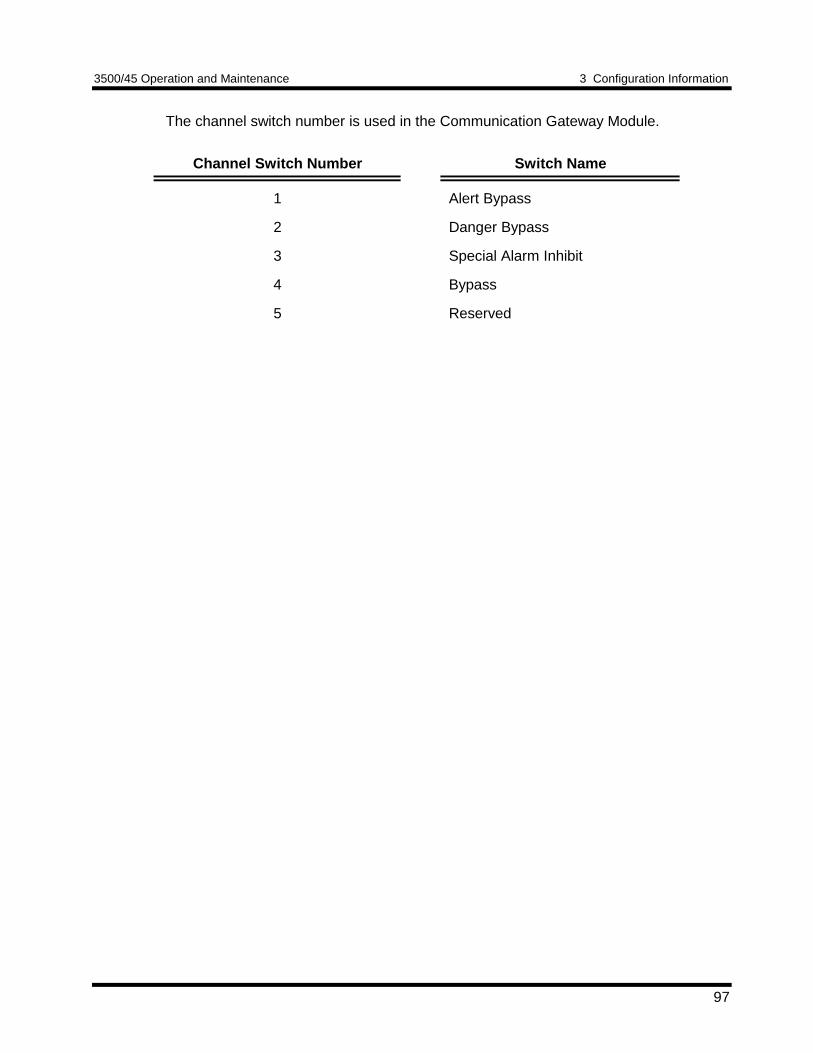
3500/45 Operation and Maintenance 3 Configuration Information
97
The channel switch number is used in the Communication Gateway Module.
Channel Switch Number Switch Name
1 Alert Bypass
2 Danger Bypass
3 Special Alarm Inhibit
4 Bypass
5 Reserved
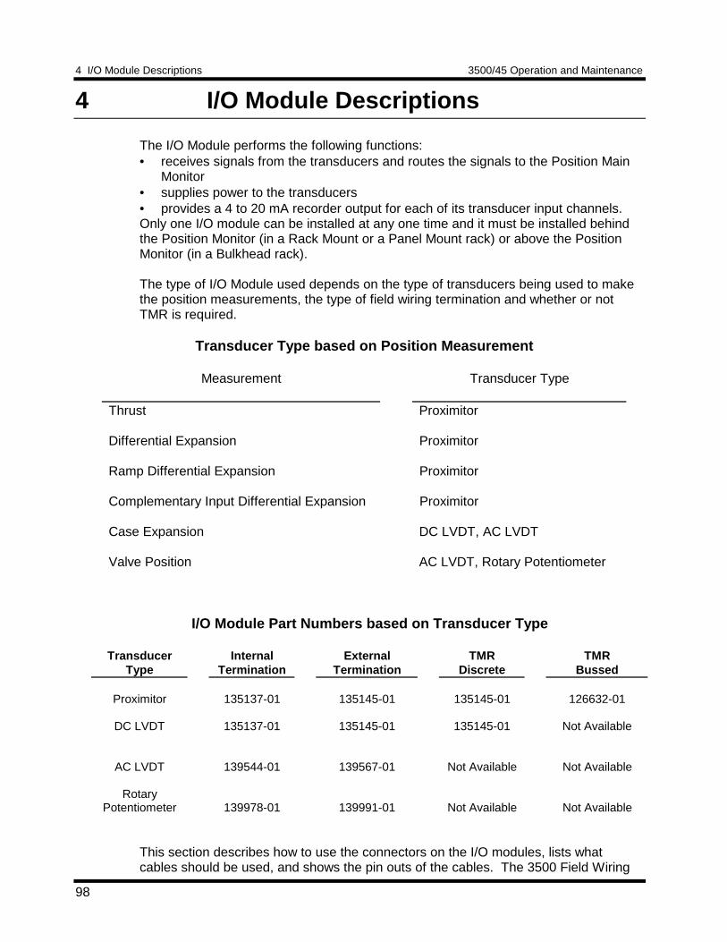
4 I/O Module Descriptions 3500/45 Operation and Maintenance
98
4 I/O Module Descriptions
The I/O Module performs the following functions:• receives signals from the transducers and routes the signals to the Position Main
Monitor• supplies power to the transducers• provides a 4 to 20 mA recorder output for each of its transducer input channels.Only one I/O module can be installed at any one time and it must be installed behindthe Position Monitor (in a Rack Mount or a Panel Mount rack) or above the PositionMonitor (in a Bulkhead rack).
The type of I/O Module used depends on the type of transducers being used to makethe position measurements, the type of field wiring termination and whether or notTMR is required.
Transducer Type based on Position Measurement
Measurement Transducer Type
Thrust Proximitor
Differential Expansion Proximitor
Ramp Differential Expansion Proximitor
Complementary Input Differential Expansion Proximitor
Case Expansion DC LVDT, AC LVDT
Valve Position AC LVDT, Rotary Potentiometer
I/O Module Part Numbers based on Transducer Type
TransducerType
InternalTermination
ExternalTermination
TMRDiscrete
TMRBussed
Proximitor 135137-01 135145-01 135145-01 126632-01
DC LVDT 135137-01 135145-01 135145-01 Not Available
AC LVDT 139544-01 139567-01 Not Available Not Available
RotaryPotentiometer 139978-01 139991-01 Not Available Not Available
This section describes how to use the connectors on the I/O modules, lists whatcables should be used, and shows the pin outs of the cables. The 3500 Field Wiring
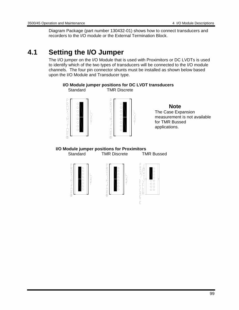
3500/45 Operation and Maintenance 4 I/O Module Descriptions
99
Diagram Package (part number 130432-01) shows how to connect transducers andrecorders to the I/O module or the External Termination Block.
4.1 Setting the I/O JumperThe I/O jumper on the I/O Module that is used with Proximitors or DC LVDTs is usedto identify which of the two types of transducers will be connected to the I/O modulechannels. The four pin connector shunts must be installed as shown below basedupon the I/O Module and Transducer type.
I/O Module jumper positions for DC LVDT transducersStandard TMR Discrete
I/O Module jumper positions for ProximitorsStandard TMR Discrete TMR Bussed
NoteThe Case Expansionmeasurement is not availablefor TMR Bussedapplications.
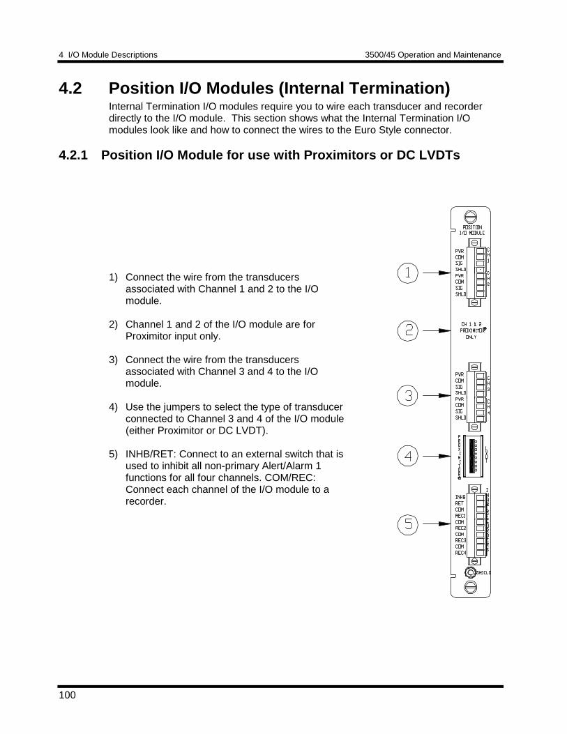
4 I/O Module Descriptions 3500/45 Operation and Maintenance
100
4.2 Position I/O Modules (Internal Termination)Internal Termination I/O modules require you to wire each transducer and recorderdirectly to the I/O module. This section shows what the Internal Termination I/Omodules look like and how to connect the wires to the Euro Style connector.
4.2.1 Position I/O Module for use with Proximitors or DC LVDTs
1) Connect the wire from the transducersassociated with Channel 1 and 2 to the I/Omodule.
2) Channel 1 and 2 of the I/O module are forProximitor input only.
3) Connect the wire from the transducersassociated with Channel 3 and 4 to the I/Omodule.
4) Use the jumpers to select the type of transducerconnected to Channel 3 and 4 of the I/O module(either Proximitor or DC LVDT).
5) INHB/RET: Connect to an external switch that isused to inhibit all non-primary Alert/Alarm 1functions for all four channels. COM/REC:Connect each channel of the I/O module to arecorder.
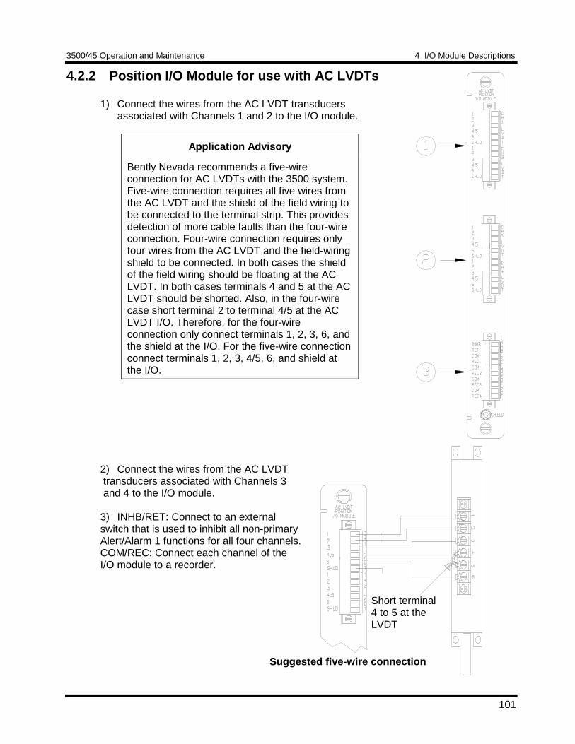
3500/45 Operation and Maintenance 4 I/O Module Descriptions
101
4.2.2 Position I/O Module for use with AC LVDTs
1) Connect the wires from the AC LVDT transducersassociated with Channels 1 and 2 to the I/O module.
Application Advisory
Bently Nevada recommends a five-wireconnection for AC LVDTs with the 3500 system.Five-wire connection requires all five wires fromthe AC LVDT and the shield of the field wiring tobe connected to the terminal strip. This providesdetection of more cable faults than the four-wireconnection. Four-wire connection requires onlyfour wires from the AC LVDT and the field-wiringshield to be connected. In both cases the shieldof the field wiring should be floating at the ACLVDT. In both cases terminals 4 and 5 at the ACLVDT should be shorted. Also, in the four-wirecase short terminal 2 to terminal 4/5 at the ACLVDT I/O. Therefore, for the four-wireconnection only connect terminals 1, 2, 3, 6, andthe shield at the I/O. For the five-wire connectionconnect terminals 1, 2, 3, 4/5, 6, and shield atthe I/O.
2) Connect the wires from the AC LVDT transducers associated with Channels 3 and 4 to the I/O module.
3) INHB/RET: Connect to an externalswitch that is used to inhibit all non-primaryAlert/Alarm 1 functions for all four channels.COM/REC: Connect each channel of theI/O module to a recorder.
Short terminal4 to 5 at theLVDT
Suggested five-wire connection
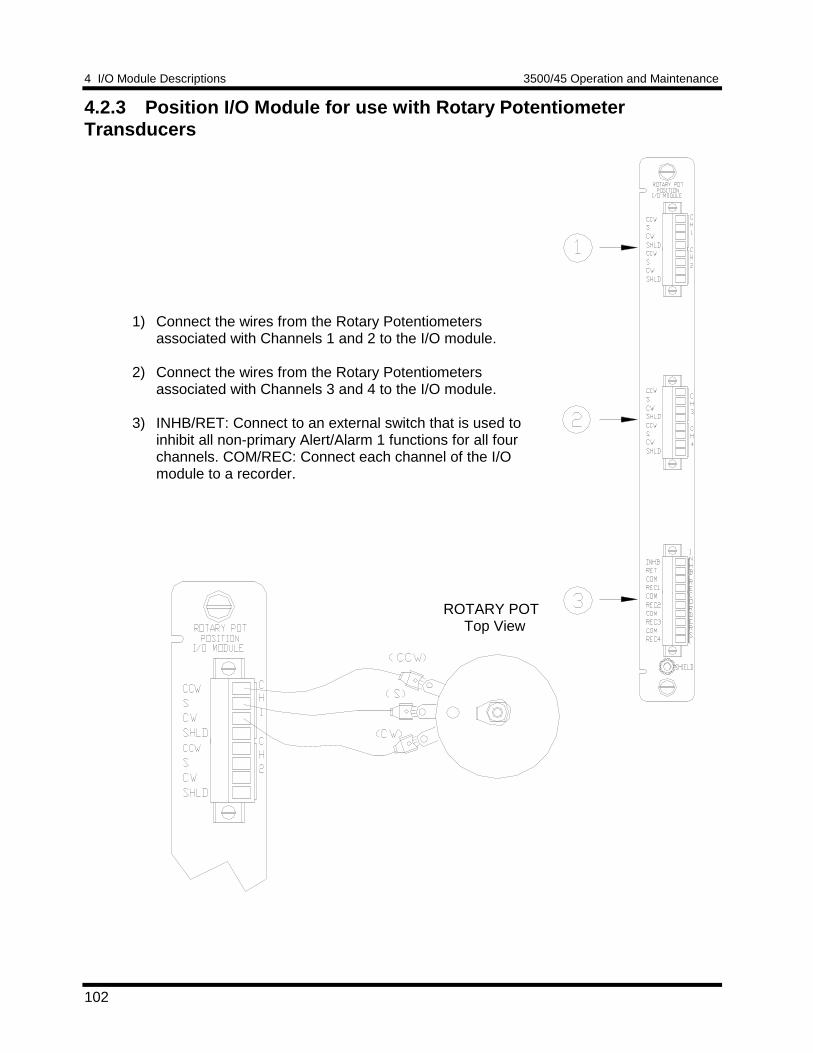
4 I/O Module Descriptions 3500/45 Operation and Maintenance
102
4.2.3 Position I/O Module for use with Rotary PotentiometerTransducers
1) Connect the wires from the Rotary Potentiometersassociated with Channels 1 and 2 to the I/O module.
2) Connect the wires from the Rotary Potentiometersassociated with Channels 3 and 4 to the I/O module.
3) INHB/RET: Connect to an external switch that is used toinhibit all non-primary Alert/Alarm 1 functions for all fourchannels. COM/REC: Connect each channel of the I/Omodule to a recorder.
ROTARY POT Top View
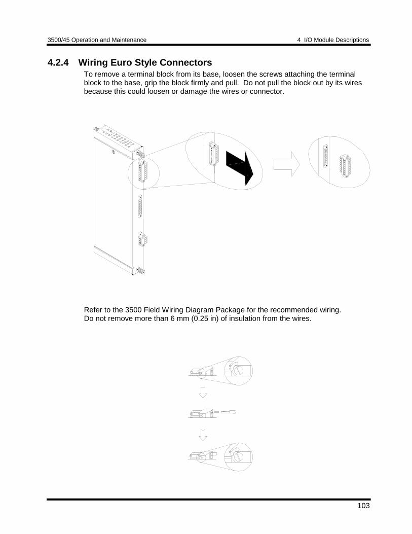
3500/45 Operation and Maintenance 4 I/O Module Descriptions
103
4.2.4 Wiring Euro Style ConnectorsTo remove a terminal block from its base, loosen the screws attaching the terminalblock to the base, grip the block firmly and pull. Do not pull the block out by its wiresbecause this could loosen or damage the wires or connector.
Refer to the 3500 Field Wiring Diagram Package for the recommended wiring.Do not remove more than 6 mm (0.25 in) of insulation from the wires.
Typical I/O module
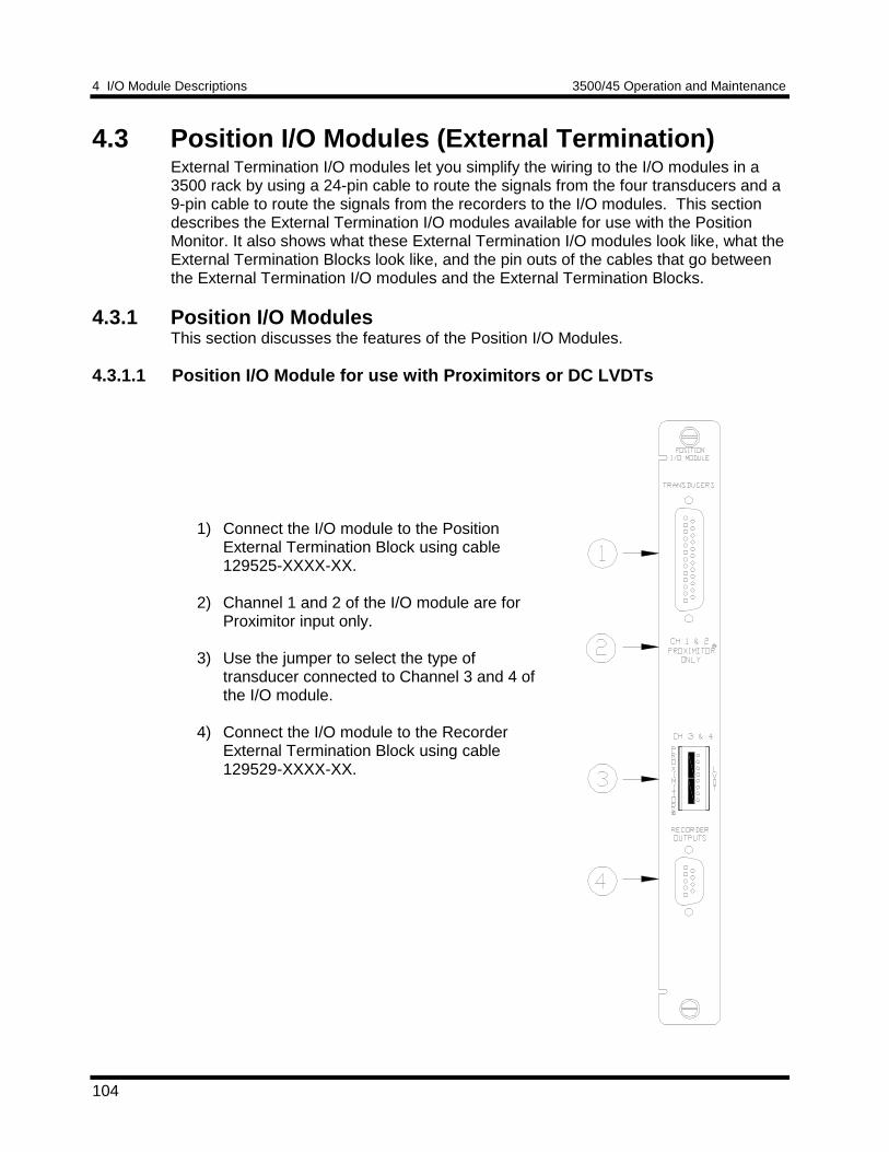
4 I/O Module Descriptions 3500/45 Operation and Maintenance
104
4.3 Position I/O Modules (External Termination)External Termination I/O modules let you simplify the wiring to the I/O modules in a3500 rack by using a 24-pin cable to route the signals from the four transducers and a9-pin cable to route the signals from the recorders to the I/O modules. This sectiondescribes the External Termination I/O modules available for use with the PositionMonitor. It also shows what these External Termination I/O modules look like, what theExternal Termination Blocks look like, and the pin outs of the cables that go betweenthe External Termination I/O modules and the External Termination Blocks.
4.3.1 Position I/O ModulesThis section discusses the features of the Position I/O Modules.
4.3.1.1 Position I/O Module for use with Proximitors or DC LVDTs
1) Connect the I/O module to the PositionExternal Termination Block using cable129525-XXXX-XX.
2) Channel 1 and 2 of the I/O module are forProximitor input only.
3) Use the jumper to select the type oftransducer connected to Channel 3 and 4 ofthe I/O module.
4) Connect the I/O module to the RecorderExternal Termination Block using cable129529-XXXX-XX.
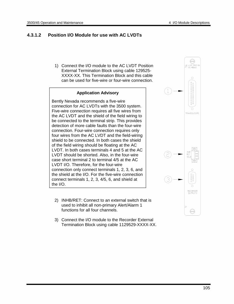
3500/45 Operation and Maintenance 4 I/O Module Descriptions
105
4.3.1.2 Position I/O Module for use with AC LVDTs
1) Connect the I/O module to the AC LVDT PositionExternal Termination Block using cable 129525-XXXX-XX. This Termination Block and this cablecan be used for five-wire or four-wire connection.
Application Advisory
Bently Nevada recommends a five-wireconnection for AC LVDTs with the 3500 system.Five-wire connection requires all five wires fromthe AC LVDT and the shield of the field wiring tobe connected to the terminal strip. This providesdetection of more cable faults than the four-wireconnection. Four-wire connection requires onlyfour wires from the AC LVDT and the field-wiringshield to be connected. In both cases the shieldof the field wiring should be floating at the ACLVDT. In both cases terminals 4 and 5 at the ACLVDT should be shorted. Also, in the four-wirecase short terminal 2 to terminal 4/5 at the ACLVDT I/O. Therefore, for the four-wireconnection only connect terminals 1, 2, 3, 6, andthe shield at the I/O. For the five-wire connectionconnect terminals 1, 2, 3, 4/5, 6, and shield atthe I/O.
2) INHB/RET: Connect to an external switch that isused to inhibit all non-primary Alert/Alarm 1functions for all four channels.
3) Connect the I/O module to the Recorder ExternalTermination Block using cable 1129529-XXXX-XX.
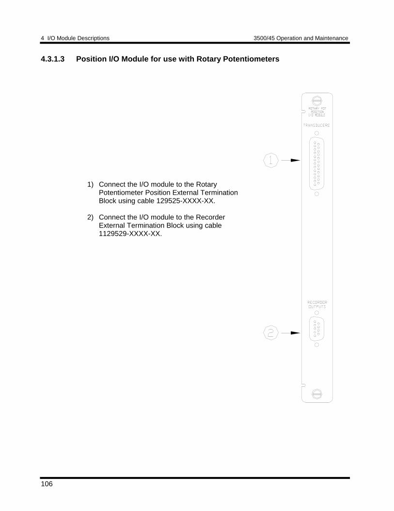
4 I/O Module Descriptions 3500/45 Operation and Maintenance
106
4.3.1.3 Position I/O Module for use with Rotary Potentiometers
1) Connect the I/O module to the RotaryPotentiometer Position External TerminationBlock using cable 129525-XXXX-XX.
2) Connect the I/O module to the RecorderExternal Termination Block using cable1129529-XXXX-XX.
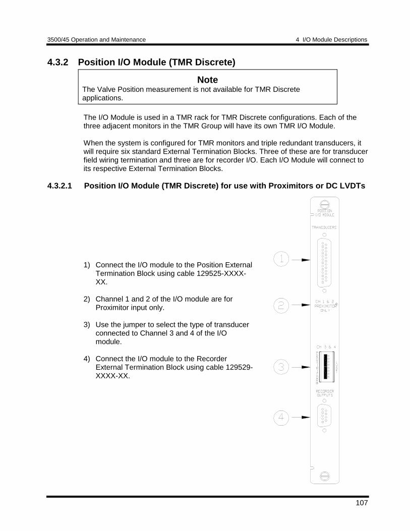
3500/45 Operation and Maintenance 4 I/O Module Descriptions
107
4.3.2 Position I/O Module (TMR Discrete)
NoteThe Valve Position measurement is not available for TMR Discreteapplications.
The I/O Module is used in a TMR rack for TMR Discrete configurations. Each of thethree adjacent monitors in the TMR Group will have its own TMR I/O Module.
When the system is configured for TMR monitors and triple redundant transducers, itwill require six standard External Termination Blocks. Three of these are for transducerfield wiring termination and three are for recorder I/O. Each I/O Module will connect toits respective External Termination Blocks.
4.3.2.1 Position I/O Module (TMR Discrete) for use with Proximitors or DC LVDTs
1) Connect the I/O module to the Position ExternalTermination Block using cable 129525-XXXX-XX.
2) Channel 1 and 2 of the I/O module are forProximitor input only.
3) Use the jumper to select the type of transducerconnected to Channel 3 and 4 of the I/Omodule.
4) Connect the I/O module to the RecorderExternal Termination Block using cable 129529-XXXX-XX.
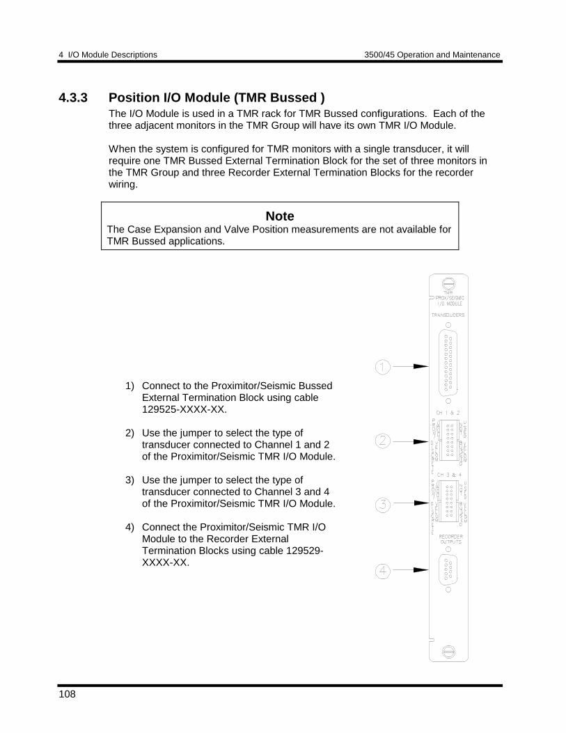
4 I/O Module Descriptions 3500/45 Operation and Maintenance
108
4.3.3 Position I/O Module (TMR Bussed )The I/O Module is used in a TMR rack for TMR Bussed configurations. Each of thethree adjacent monitors in the TMR Group will have its own TMR I/O Module.
When the system is configured for TMR monitors with a single transducer, it willrequire one TMR Bussed External Termination Block for the set of three monitors inthe TMR Group and three Recorder External Termination Blocks for the recorderwiring.
NoteThe Case Expansion and Valve Position measurements are not available forTMR Bussed applications.
1) Connect to the Proximitor/Seismic BussedExternal Termination Block using cable129525-XXXX-XX.
2) Use the jumper to select the type oftransducer connected to Channel 1 and 2of the Proximitor/Seismic TMR I/O Module.
3) Use the jumper to select the type oftransducer connected to Channel 3 and 4of the Proximitor/Seismic TMR I/O Module.
4) Connect the Proximitor/Seismic TMR I/OModule to the Recorder ExternalTermination Blocks using cable 129529-XXXX-XX.
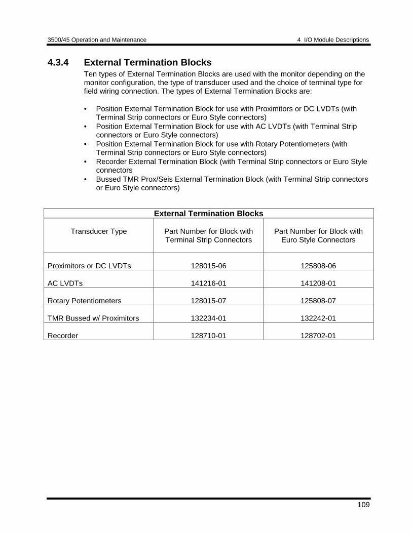
3500/45 Operation and Maintenance 4 I/O Module Descriptions
109
4.3.4 External Termination BlocksTen types of External Termination Blocks are used with the monitor depending on themonitor configuration, the type of transducer used and the choice of terminal type forfield wiring connection. The types of External Termination Blocks are:
• Position External Termination Block for use with Proximitors or DC LVDTs (withTerminal Strip connectors or Euro Style connectors)
• Position External Termination Block for use with AC LVDTs (with Terminal Stripconnectors or Euro Style connectors)
• Position External Termination Block for use with Rotary Potentiometers (withTerminal Strip connectors or Euro Style connectors)
• Recorder External Termination Block (with Terminal Strip connectors or Euro Styleconnectors
• Bussed TMR Prox/Seis External Termination Block (with Terminal Strip connectorsor Euro Style connectors)
External Termination Blocks
Transducer Type Part Number for Block withTerminal Strip Connectors
Part Number for Block withEuro Style Connectors
Proximitors or DC LVDTs 128015-06 125808-06
AC LVDTs 141216-01 141208-01
Rotary Potentiometers 128015-07 125808-07
TMR Bussed w/ Proximitors 132234-01 132242-01
Recorder 128710-01 128702-01
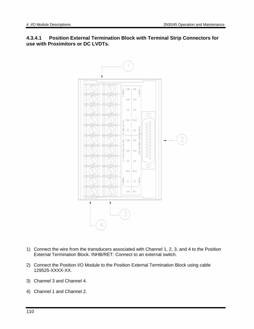
4 I/O Module Descriptions 3500/45 Operation and Maintenance
110
4.3.4.1 Position External Termination Block with Terminal Strip Connectors foruse with Proximitors or DC LVDTs.
1) Connect the wire from the transducers associated with Channel 1, 2, 3, and 4 to the PositionExternal Termination Block. INHB/RET: Connect to an external switch.
2) Connect the Position I/O Module to the Position External Termination Block using cable129525-XXXX-XX.
3) Channel 3 and Channel 4.
4) Channel 1 and Channel 2.
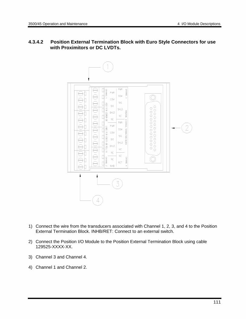
3500/45 Operation and Maintenance 4 I/O Module Descriptions
111
4.3.4.2 Position External Termination Block with Euro Style Connectors for usewith Proximitors or DC LVDTs.
1) Connect the wire from the transducers associated with Channel 1, 2, 3, and 4 to the PositionExternal Termination Block. INHB/RET: Connect to an external switch.
2) Connect the Position I/O Module to the Position External Termination Block using cable129525-XXXX-XX.
3) Channel 3 and Channel 4.
4) Channel 1 and Channel 2.
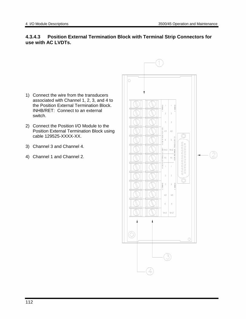
4 I/O Module Descriptions 3500/45 Operation and Maintenance
112
4.3.4.3 Position External Termination Block with Terminal Strip Connectors foruse with AC LVDTs.
1) Connect the wire from the transducersassociated with Channel 1, 2, 3, and 4 tothe Position External Termination Block.INHB/RET: Connect to an externalswitch.
2) Connect the Position I/O Module to thePosition External Termination Block usingcable 129525-XXXX-XX.
3) Channel 3 and Channel 4.
4) Channel 1 and Channel 2.
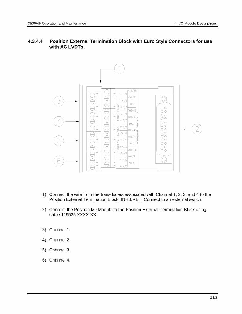
3500/45 Operation and Maintenance 4 I/O Module Descriptions
113
4.3.4.4 Position External Termination Block with Euro Style Connectors for usewith AC LVDTs.
1) Connect the wire from the transducers associated with Channel 1, 2, 3, and 4 to thePosition External Termination Block. INHB/RET: Connect to an external switch.
2) Connect the Position I/O Module to the Position External Termination Block usingcable 129525-XXXX-XX.
3) Channel 1.
4) Channel 2.
5) Channel 3.
6) Channel 4.
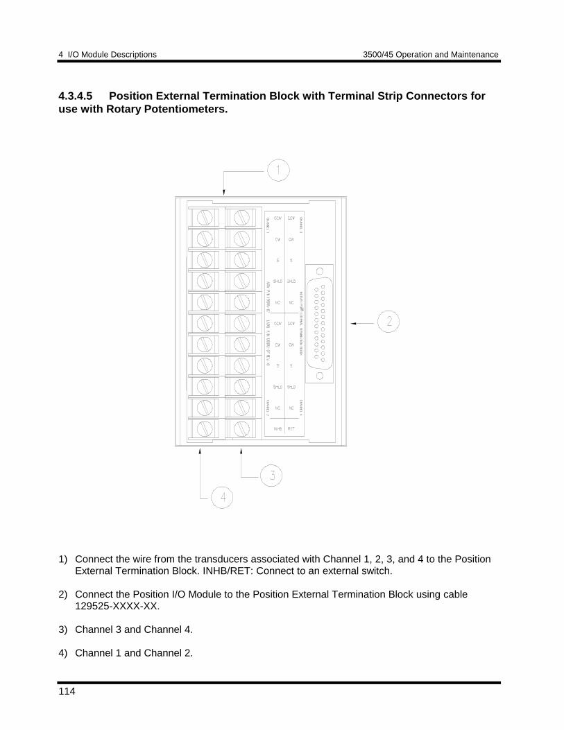
4 I/O Module Descriptions 3500/45 Operation and Maintenance
114
4.3.4.5 Position External Termination Block with Terminal Strip Connectors foruse with Rotary Potentiometers.
1) Connect the wire from the transducers associated with Channel 1, 2, 3, and 4 to the PositionExternal Termination Block. INHB/RET: Connect to an external switch.
2) Connect the Position I/O Module to the Position External Termination Block using cable129525-XXXX-XX.
3) Channel 3 and Channel 4.
4) Channel 1 and Channel 2.
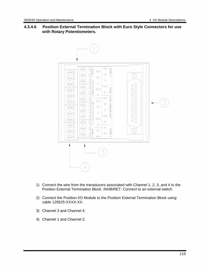
3500/45 Operation and Maintenance 4 I/O Module Descriptions
115
4.3.4.6 Position External Termination Block with Euro Style Connectors for usewith Rotary Potentiometers.
1) Connect the wire from the transducers associated with Channel 1, 2, 3, and 4 to thePosition External Termination Block. INHB/RET: Connect to an external switch.
2) Connect the Position I/O Module to the Position External Termination Block usingcable 129525-XXXX-XX.
3) Channel 3 and Channel 4.
4) Channel 1 and Channel 2.
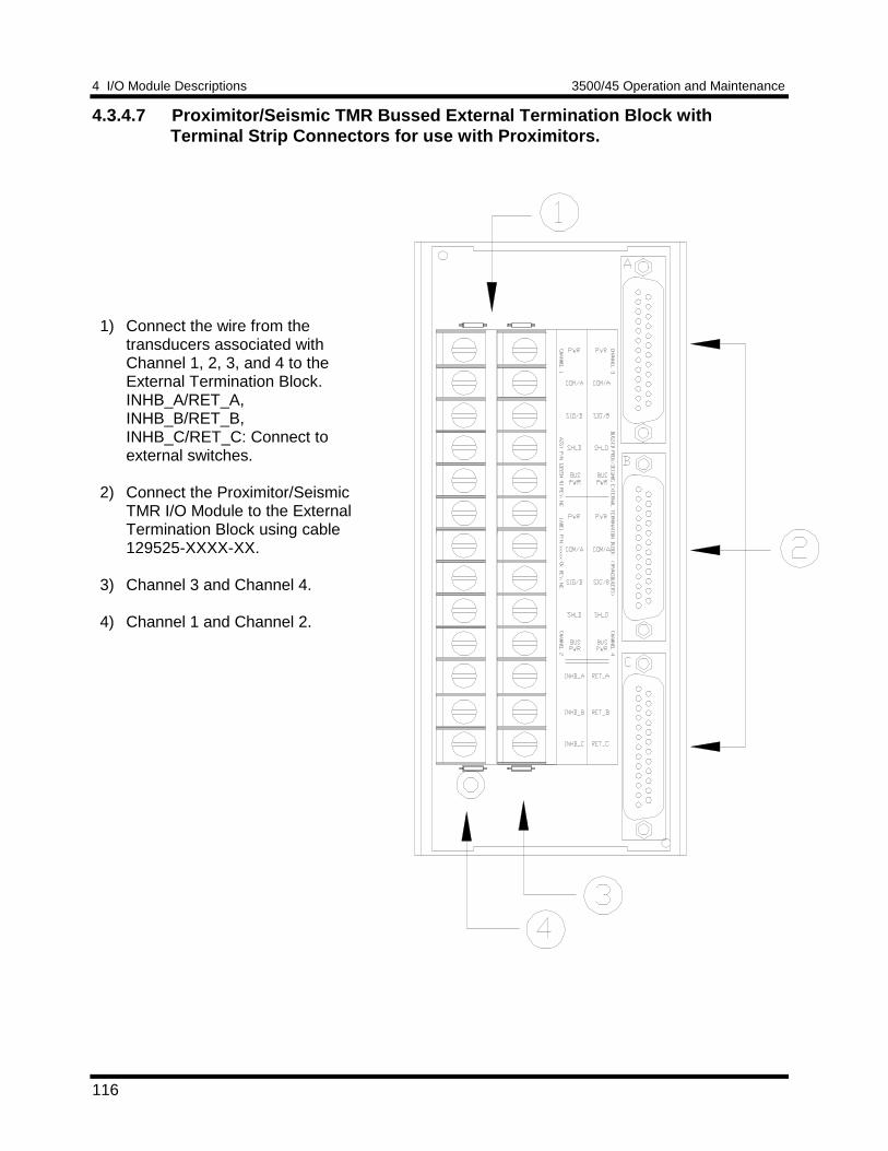
4 I/O Module Descriptions 3500/45 Operation and Maintenance
116
4.3.4.7 Proximitor/Seismic TMR Bussed External Termination Block withTerminal Strip Connectors for use with Proximitors.
1) Connect the wire from thetransducers associated withChannel 1, 2, 3, and 4 to theExternal Termination Block.INHB_A/RET_A,INHB_B/RET_B,INHB_C/RET_C: Connect toexternal switches.
2) Connect the Proximitor/SeismicTMR I/O Module to the ExternalTermination Block using cable129525-XXXX-XX.
3) Channel 3 and Channel 4.
4) Channel 1 and Channel 2.
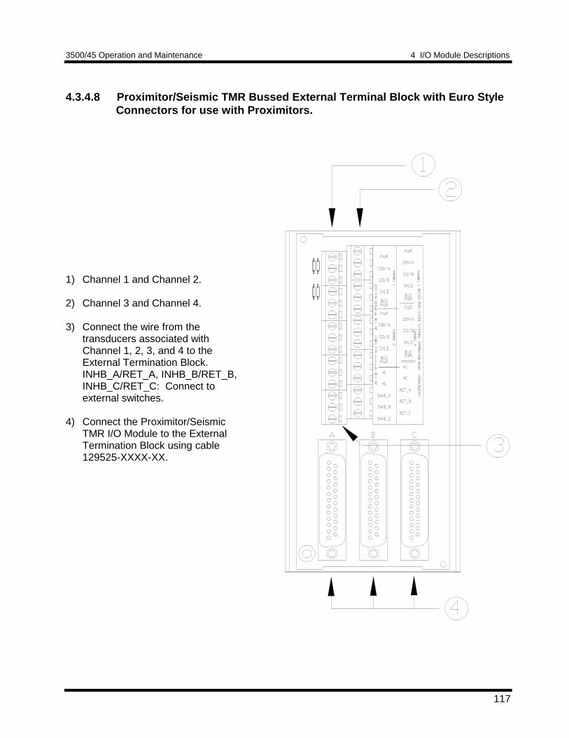
3500/45 Operation and Maintenance 4 I/O Module Descriptions
117
4.3.4.8 Proximitor/Seismic TMR Bussed External Terminal Block with Euro StyleConnectors for use with Proximitors.
1) Channel 1 and Channel 2.
2) Channel 3 and Channel 4.
3) Connect the wire from thetransducers associated withChannel 1, 2, 3, and 4 to theExternal Termination Block.INHB_A/RET_A, INHB_B/RET_B,INHB_C/RET_C: Connect toexternal switches.
4) Connect the Proximitor/SeismicTMR I/O Module to the ExternalTermination Block using cable129525-XXXX-XX.
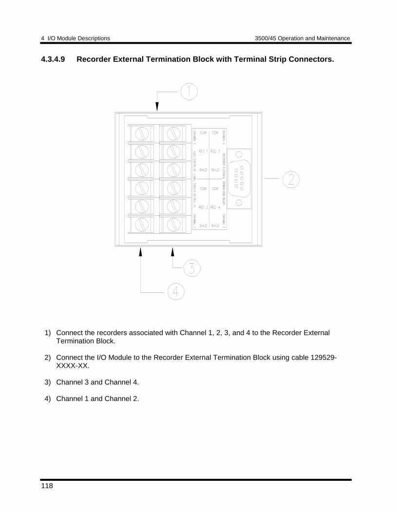
4 I/O Module Descriptions 3500/45 Operation and Maintenance
118
4.3.4.9 Recorder External Termination Block with Terminal Strip Connectors.
1) Connect the recorders associated with Channel 1, 2, 3, and 4 to the Recorder ExternalTermination Block.
2) Connect the I/O Module to the Recorder External Termination Block using cable 129529-XXXX-XX.
3) Channel 3 and Channel 4.
4) Channel 1 and Channel 2.
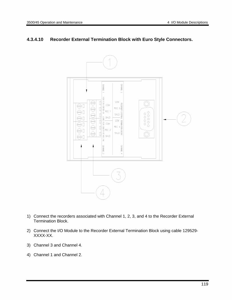
3500/45 Operation and Maintenance 4 I/O Module Descriptions
119
4.3.4.10 Recorder External Termination Block with Euro Style Connectors.
1) Connect the recorders associated with Channel 1, 2, 3, and 4 to the Recorder ExternalTermination Block.
2) Connect the I/O Module to the Recorder External Termination Block using cable 129529-XXXX-XX.
3) Channel 3 and Channel 4.
4) Channel 1 and Channel 2.
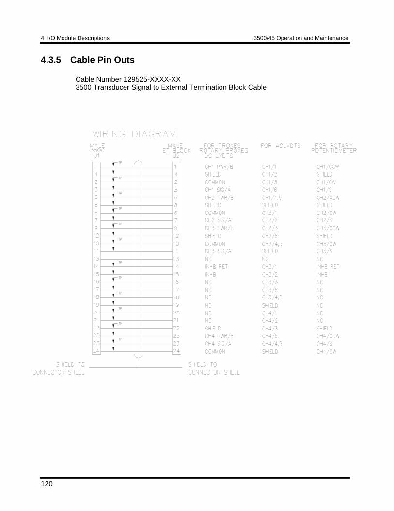
4 I/O Module Descriptions 3500/45 Operation and Maintenance
120
4.3.5 Cable Pin Outs
Cable Number 129525-XXXX-XX3500 Transducer Signal to External Termination Block Cable
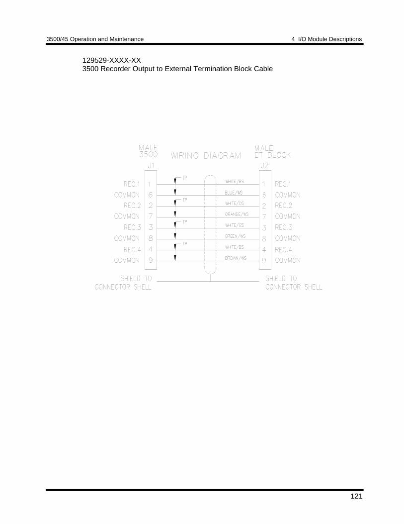
3500/45 Operation and Maintenance 4 I/O Module Descriptions
121
129529-XXXX-XX3500 Recorder Output to External Termination Block Cable
5 Maintenance 3500/45 Operation and Maintenance
122
5 Maintenance
The boards and components inside of 3500 modules cannot be repaired in the field.Maintaining a 3500 rack consists of testing module channels to verify that they areoperating correctly. Modules that are not operating correctly should be replaced with aspare.
When performed properly, this module may be installed into or removed from the rackwhile power is applied to the rack. Refer to the Rack Installation and MaintenanceManual (part number 129766-01) for proper procedure.
This section shows how to verify the operation of channels (Section 5.1); how toadjust the scale factor, channel sensitivity, zero position, and cross over voltage forthrust and differential expansion channels (Section 5.2); and how to adjust sensitivity,upscale and downscale voltage for case expansion channels (Section 5.3); how toadjust sensitivitiy, upscale and downscale voltages for valve positionchannels(Section 5.4); and how to upgrade firmware (Section 5.5) .
5.1 Verifying a 3500 Rack - Position Monitor ModuleThe 3500 Monitoring System is a precision instrument that requires no calibration.The functions of monitor channels, however, must be verified at regular intervals. Ateach maintenance interval, we recommend that you use the procedures in thissection to verify the operation of all active channels in the monitor. It is onlynecessary to verify the alarms and accuracy of channel proportional values that areactive.
3500/45 Operation and Maintenance 5 Maintenance
123
SectionNumber
Topic PageNumber
5.1.1 Choosing a Maintenance Interval 123
5.1.2 Required Test Equipment 123
5.1.3 Typical Verification Test Setup 124
5.1.4 Using the Rack Configuration Software 126
5.1.5 Thrust Position and Differential ExpansionChannels
129
5.1.6 Ramp Differential Expansion Channels 140
5.1.7 Complementary Input DifferentialExpansion Channels
156
5.1.8 Case Expansion Channels 166
5.1.9 Valve Position Channels 181
5.1.10 Verify Recorder Outputs 195
5.1.11 If a Channel Fails a Verification Test 196
5.1.1 Choosing a Maintenance IntervalUse the following approach to choose a maintenance interval:• Start with an interval of one year and then shorten the interval if any of the
following conditions apply:− the monitored machine is classified as critical− the 3500 rack is operating in a harsh environment such as in extreme
temperature• At each interval, use the results of the previous verifications and ISO Procedure
10012-1 to adjust the interval.
5.1.2 Required Test EquipmentThe verification procedures in this section require the following test equipment.
Thrust Position and Differential Expansion Channels• Power Supply (single channel)• Multimeter - 4 ½ digits
Ramp Differential Expansion Channels• Power Supply (dual channel or 2 single channel supplies)• Multimeter - 4 ½ digits
Complementary Input Differential Expansion Channels• Power Supply (dual channel or 2 single channel supplies)• Multimeter - 4 ½ digits
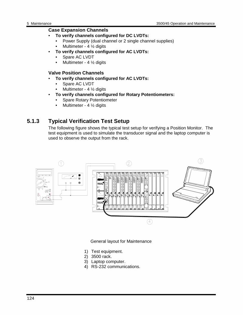
5 Maintenance 3500/45 Operation and Maintenance
124
Case Expansion Channels• To verify channels configured for DC LVDTs:
• Power Supply (dual channel or 2 single channel supplies)• Multimeter - 4 ½ digits
• To verify channels configured for AC LVDTs:• Spare AC LVDT• Multimeter - 4 ½ digits
Valve Position Channels• To verify channels configured for AC LVDTs:
• Spare AC LVDT• Multimeter - 4 ½ digits
• To verify channels configured for Rotary Potentiometers:• Spare Rotary Potentiometer• Multimeter - 4 ½ digits
5.1.3 Typical Verification Test SetupThe following figure shows the typical test setup for verifying a Position Monitor. Thetest equipment is used to simulate the transducer signal and the laptop computer isused to observe the output from the rack.
General layout for Maintenance
1) Test equipment.2) 3500 rack.3) Laptop computer.4) RS-232 communications.
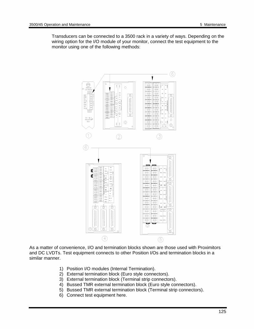
3500/45 Operation and Maintenance 5 Maintenance
125
Transducers can be connected to a 3500 rack in a variety of ways. Depending on thewiring option for the I/O module of your monitor, connect the test equipment to themonitor using one of the following methods:
As a matter of convenience, I/O and termination blocks shown are those used with Proximitorsand DC LVDTs. Test equipment connects to other Position I/Os and termination blocks in asimilar manner.
1) Position I/O modules (Internal Termination).2) External termination block (Euro style connectors).3) External termination block (Terminal strip connectors).4) Bussed TMR external termination block (Euro style connectors).5) Bussed TMR external termination block (Terminal strip connectors).6) Connect test equipment here.
5 Maintenance 3500/45 Operation and Maintenance
126
5.1.4 Using the Rack Configuration SoftwareThe laptop computer that is part of the test setup uses the Rack ConfigurationSoftware to display output from the rack and to reset certain operating parameters inthe rack. To perform the test procedures in this section you must be familiar with thefollowing features of the Rack Configuration Software:• upload, download, and save configuration files• enable and disable channels and alarms• bypass channels and alarms• display the Verification screen
The Rack Configuration and Test Utilities Guide (part number 129777-01) explainshow to perform these operations.
NoteIt is important to save the original rack configuration before doing anyMaintenance or Troubleshooting Procedures. It may be necessary duringthese procedures to change setpoints, etc. which must be restored to theiroriginal values at the conclusion of the procedures. At that time the originalconfiguration should be downloaded to the rack.
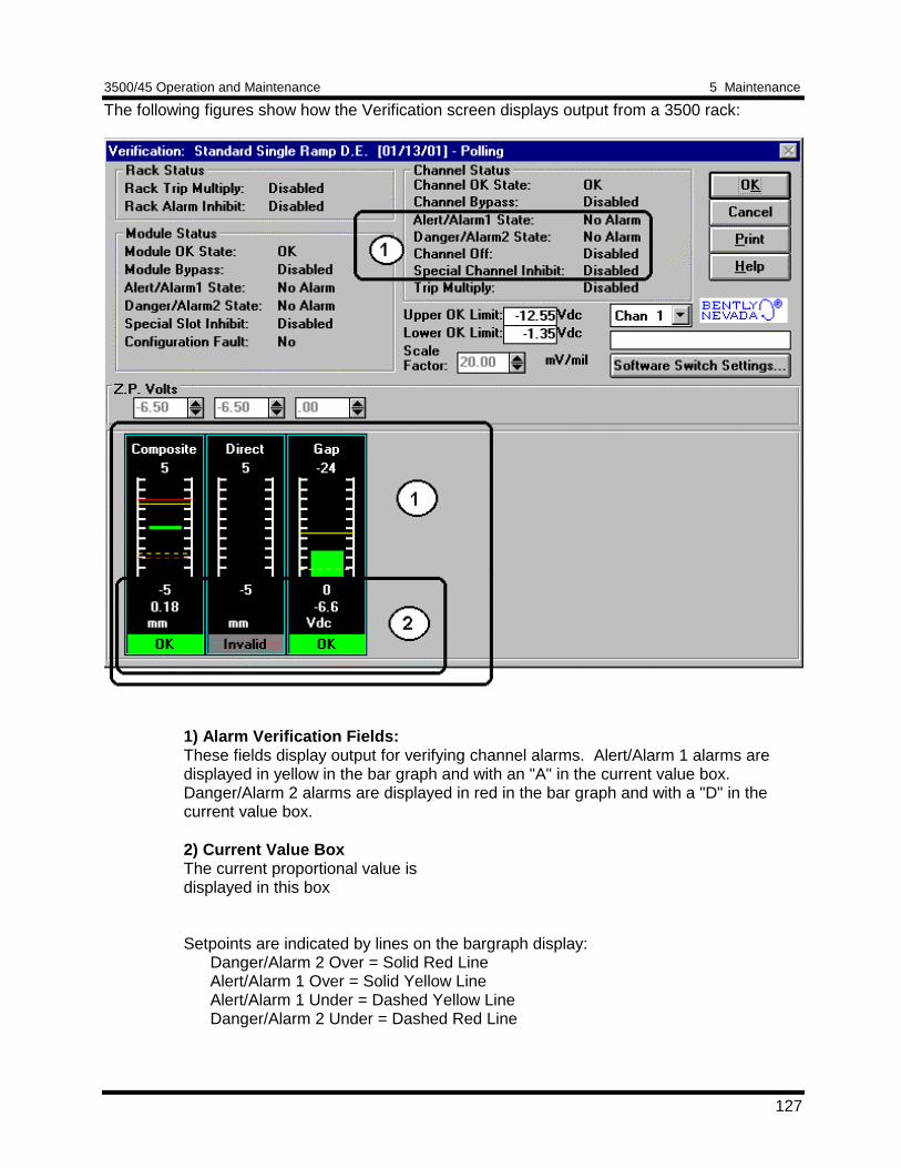
3500/45 Operation and Maintenance 5 Maintenance
127
The following figures show how the Verification screen displays output from a 3500 rack:
1) Alarm Verification Fields:These fields display output for verifying channel alarms. Alert/Alarm 1 alarms aredisplayed in yellow in the bar graph and with an "A" in the current value box.Danger/Alarm 2 alarms are displayed in red in the bar graph and with a "D" in thecurrent value box.
2) Current Value BoxThe current proportional value isdisplayed in this box
Setpoints are indicated by lines on the bargraph display:Danger/Alarm 2 Over = Solid Red LineAlert/Alarm 1 Over = Solid Yellow LineAlert/Alarm 1 Under = Dashed Yellow LineDanger/Alarm 2 Under = Dashed Red Line
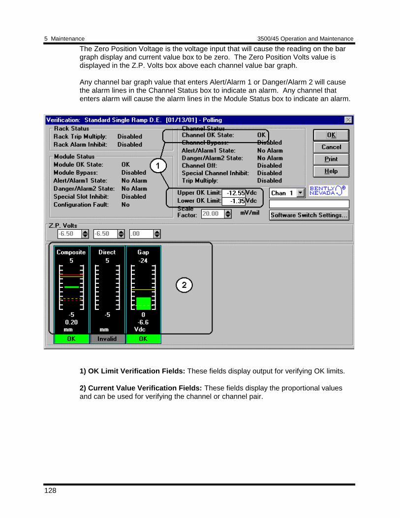
5 Maintenance 3500/45 Operation and Maintenance
128
The Zero Position Voltage is the voltage input that will cause the reading on the bargraph display and current value box to be zero. The Zero Position Volts value isdisplayed in the Z.P. Volts box above each channel value bar graph.
Any channel bar graph value that enters Alert/Alarm 1 or Danger/Alarm 2 will causethe alarm lines in the Channel Status box to indicate an alarm. Any channel thatenters alarm will cause the alarm lines in the Module Status box to indicate an alarm.
1) OK Limit Verification Fields: These fields display output for verifying OK limits.
2) Current Value Verification Fields: These fields display the proportional valuesand can be used for verifying the channel or channel pair.
3500/45 Operation and Maintenance 5 Maintenance
129
5.1.5 Thrust Position and Differential Expansion ChannelsThe following sections describe how to test alarms, verify channels, and test OK limitsfor channels configured as Thrust Position and Differential Expansion. The outputvalues and alarm setpoints are verified by varying the input DC voltage from a powersupply and observing that the correct results are reported in the Verification screen onthe test computer.
Thrust Position and Differential Expansion channels can be configured for thefollowing channel values and alarms:
Channel Values Alarms
Over Under
Direct
Gap
5.1.5.1 Test Equipment and Software Setup - Thrust Position and DifferentialExpansionThe following test equipment and software setup can be used as the initial setupneeded for all the Thrust Position and Differential Expansion channel verificationprocedures (Test Alarms, Verify Channels, and Test OK Limits).
Application Alert
Tests will exceed alarmsetpoint levels causingalarms to activate. Thiscould result in a relaycontact state change.
WARNING
High voltage present.Contact could causeshock, burns, or death.
Do not touch exposedwires or terminals.
Application Alert
Disconnecting fieldwiring will cause a notOK condition.
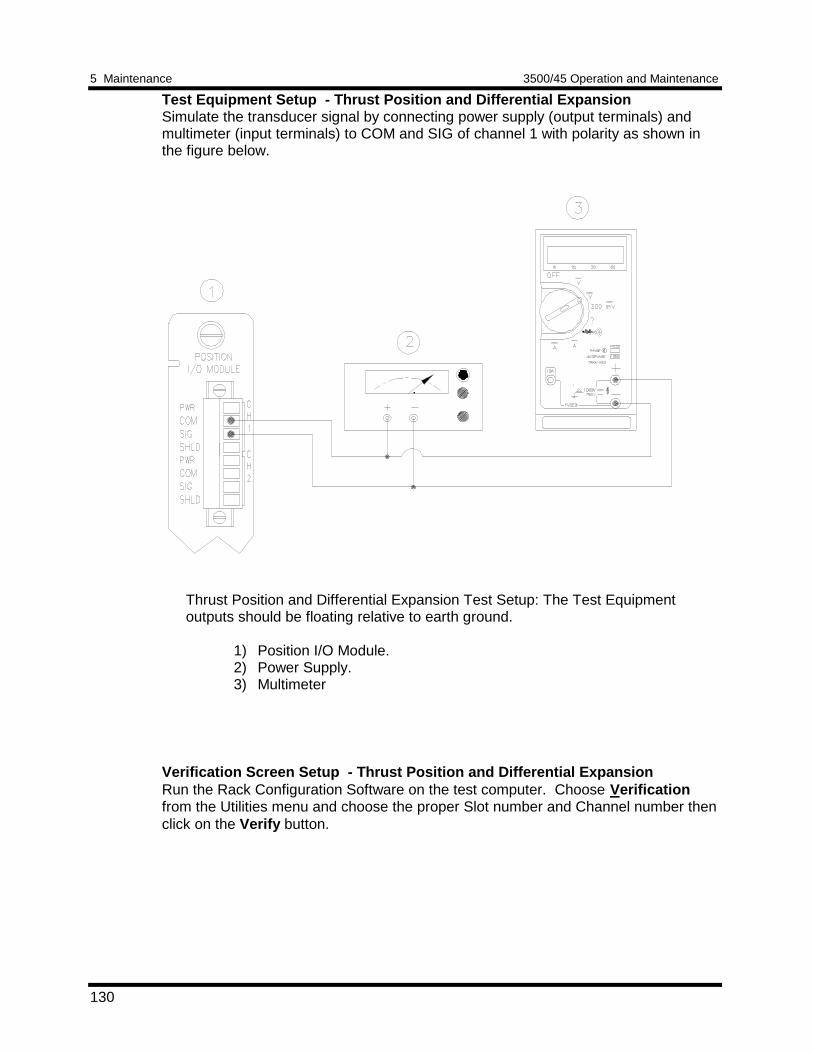
5 Maintenance 3500/45 Operation and Maintenance
130
Test Equipment Setup - Thrust Position and Differential ExpansionSimulate the transducer signal by connecting power supply (output terminals) andmultimeter (input terminals) to COM and SIG of channel 1 with polarity as shown inthe figure below.
Thrust Position and Differential Expansion Test Setup: The Test Equipmentoutputs should be floating relative to earth ground.
1) Position I/O Module.2) Power Supply.3) Multimeter
Verification Screen Setup - Thrust Position and Differential ExpansionRun the Rack Configuration Software on the test computer. Choose Verificationfrom the Utilities menu and choose the proper Slot number and Channel number thenclick on the Verify button.
3500/45 Operation and Maintenance 5 Maintenance
131
The following table directs you to the starting page of each maintenance sectionassociated with the Thrust Position and Differential Expansion Channels.
SectionNumber
Topic PageNumber
5.1.5.2 Test Alarms - Direct 131
5.1.5.2 Test Alarms - Gap 131
5.1.5.3 Verify Channel Values - Direct 134
5.1.5.3 Verify Channel Values - Gap 134
5.1.5.4 Test OK Limits 137
5.1.5.2 Test Alarms - Thrust Position and Differential ExpansionThe general approach for testing alarm setpoints is to simulate the Thrust Positionand Differential Expansion signal with a power supply. The alarm levels are tested byvarying the DC voltage and observing that the correct results are reported in theVerification screen on the test computer. It is only necessary to test those alarmparameters that are configured and being used. The general test procedure to verifycurrent alarm operation will include simulating a transducer input signal and varyingthis signal:1. to exceed over Alert/Alarm 1 and Danger/Alarm 2 Setpoints2. to drop below any under Alert/Alarm 1 and Danger/Alarm 2 Setpoints3. to produce a nonalarm condition.
Direct
1. Disconnect PWR, COM, and SIG field wiring from the channel terminals onthe I/O Module.
2. Connect test equipment and run software as described in Section 5.1.5.1
(Test Equipment and Software Setup - Thrust Position and DifferentialExpansion).
3. Adjust the power supply to produce a voltage that is within the Direct setpoint
levels on the Direct bar graph display of the Verification screen. 4. Press the RESET switch on the Rack Interface Module (RIM). Verify that the
OK LED is on, the bar graph indicator for Direct is green, and the CurrentValue Box has no alarm indication.
5. Adjust the power supply voltage such that the signal just exceeds the DirectOver Alert/Alarm 1 setpoint level. Wait for 2 or 3 seconds after the alarm timedelay expires and verify that the bar graph indicator for Direct changes colorfrom green to yellow.
5 Maintenance 3500/45 Operation and Maintenance
132
6. Press the RESET switch on the Rack Interface Module (RIM). Verify that thebar graph indicator for Direct remains yellow.
7. Adjust the power supply such that the signal just exceeds the Direct Over
Danger/Alarm 2 setpoint level. Wait for 2 or 3 seconds after the alarm timedelay expires and verify that the bar graph indicator for Direct changes colorfrom yellow to red.
8. Press the RESET switch on the Rack Interface Module (RIM). Verify that the
bar graph indicator for Direct remains red. 9. Adjust the power supply voltage such that the signal reads below the Over
Alarm setpoint levels. If the nonlatching option is configured, observe that thebar graph indicator for Direct changes color to green and that the CurrentValue Box contains no indication of alarms. Press the RESET switch on theRack Interface Module (RIM) to reset latching alarms.
10. Repeat steps 3 through 9 to test the Under Alert/Alarm 1 and Under
Danger/Alarm 2 setpoints by adjusting the power supply to exceed the UnderAlarm setpoint levels.
11. If you cannot verify any configured alarm, recheck the configured setpoints. If
the monitor still does not alarm properly or fails any other part of this test, goto Section 5.1.11 (If a Channel Fails a Verification Test).
12. Disconnect the test equipment and reconnect the PWR, COM, and SIG field
wiring to the channel terminals on the I/O Module. Verify that the OK LEDcomes on and the OK relay energizes. Press the RESET switch on the RackInterface Module (RIM) to reset the OK LED.
13. Repeat steps 1 through 12 for all configured channels.
Gap
1. Disconnect PWR, COM, and SIG field wiring from the channel terminals onthe I/O Module.
2. Connect test equipment and run software as described in Section 5.1.5.1
(Test Equipment and Software Setup - Thrust Position and DifferentialExpansion).
3. Adjust the power supply to produce a voltage that is within the Gap setpoint
levels on the Gap bar graph display.
4. Press the RESET switch on the Rack Interface Module (RIM). Verify that theOK LED is on, the bar graph indicator for Gap is green, and the Current ValueBox has no alarm indication.
5. Adjust the power supply voltage such that the signal just exceeds the Gap
Over Alert/Alarm 1 setpoint level. Wait for 2 or 3 seconds until the alarm timedelay expires and verify that the bar graph indicator for Gap changes colorfrom green to yellow.
3500/45 Operation and Maintenance 5 Maintenance
133
6. Press the RESET switch on the Rack Interface Module (RIM). Verify that the
bar graph indicator for Gap remains yellow. 7. Adjust the power supply such that the signal just exceeds the Gap Over
Danger/Alarm 2 setpoint level. Wait for 2 or 3 seconds after the alarm timedelay expires and verify that the bar graph indicator for Gap changes colorfrom yellow to red.
8. Press the RESET switch on the Rack Interface Module (RIM). Verify that the
bar graph indicator for Gap remains red. 9. Adjust the power supply voltage such that the signal reads below the Over
Alarm setpoint levels. If the nonlatching option is configured, observe that thebar graph indicator for Gap changes color to green and that the Current ValueBox contains no indication of alarms. Press the RESET switch on the RackInterface Module (RIM) to reset latching alarms.
10. Repeat steps 5 through 9 to test the Under Alert/Alarm 1 and Under
Danger/Alarm 2 setpoints by adjusting the power supply to exceed the UnderAlarm setpoint levels.
11. If you cannot verify any configured alarm, recheck the configured setpoints. If
the monitor still does not alarm properly or fails any other part of this test, goto Section 5.1.11 (If a Channel Fails a Verification Test).
12. Disconnect the test equipment and reconnect the PWR, COM, and SIG field
wiring to the channel terminals on the I/O Module. Verify that the OK LEDcomes on and the OK relay energizes. Press the RESET switch on the RackInterface Module (RIM) to reset the OK LED.
13. Repeat steps 1 through 12 for all configured channels.
5 Maintenance 3500/45 Operation and Maintenance
134
5.1.5.3 Verify Channel Values - Thrust Position and Differential ExpansionThe general approach for testing these parameters is to simulate the Thrust Positionand Differential Expansion signal with a power supply. The output values are verifiedby varying the input DC voltage and observing that the correct results are reported inthe Verification screen on the test computer.
Direct
1. Disconnect PWR, COM, and SIG field wiring from the channel terminals onthe I/O Module.
2. Connect test equipment and run software as described in Section 5.1.5.1
(Test Equipment and Software Setup - Thrust Position and DifferentialExpansion).
3. Calculate the full-scale and bottom scale values. These values can be
calculated in the following way:
Full-scale Value, Bottom-scale Value =Zero Position Voltage ± (Transducer Scale Factor X Scale Range)
NoteThe Zero Position Voltage is the voltage input that will cause the reading on thebar graph display and the Current Value Box to be zero. The Zero Position Voltsvalue is displayed in the Z.P. Volts box above each channel value bar graph.
NoteIf the bottom scale range is zero (for example 0 to 80 mil), use the Full-scaleValue formula.
NoteUse the Transducer Scale Factor displayed in the Scale Factor Box on theVerification Screen.
3500/45 Operation and Maintenance 5 Maintenance
135
If Upscale direction ( Normal for Thrust, Long for Differential Expansion ) is towardthe probe:
Full-scale =(Zero Position Voltage) + (Transducer Scale Factor X Top Meter Scale )
Bottom Scale =(Zero Position Voltage) - (Transducer Scale Factor X ABS ( Bottom Meter Scale )
Example 1 :Transducer scale factor = 200 mV/milMeter scale range = 25 - 0 - 25 milZero Position Voltage = - 9.75 Vdc
Full-scale Value = ( -9.75 ) + ( 0.200 X 25 )= -4.75 Vdc
Bottom-scale Value = ( -9.75 ) - ( 0.200 X 25 )= -14.75 Vdc
Example 2 :Transducer scale factor = 7,874 mV/mmMeter scale range = 1 - 0 - 1 mmZero Position Voltage = -10.16 Vdc
Full-scale Value = ( -10.16 ) + ( 7.874 X 1 )= -2.286 Vdc
Bottom-scale Value = ( -10.16 ) - ( 7.874 X 1 )= -18.03 Vdc
• If Upscale direction ( Normal for Thrust, Long for Differential Expansion ) isaway from the probe:
Full scale = (Zero Position Voltage) - (Transducer Scale Factor X Top Meter Scale )
Bottom Scale = (Zero Position Voltage) + (Transducer Scale Factor X ABS( Bottom Meter Scale )
Example 1 :Transducer scale factor = 200 mV/milMeter scale range = 25 - 0 - 25 milZero Position Voltage = - 9.75 Vdc
Full-scale Value = ( -9.75 ) - ( 0.200 X 25 )= -14.75 Vdc
Bottom-scale Value = ( -9.75 ) + ( 0.200 X 25 )= -4.75 Vdc
5 Maintenance 3500/45 Operation and Maintenance
136
Example 2 :Transducer scale factor = 7,874 mV/mmMeter scale range = 1 - 0 - 1 mmZero Position Voltage = -10.16 Vdc
Full-scale Value = ( -10.16 ) - ( 7.874 X 1 )= -18.03 Vdc
Bottom-scale Value = ( -10.16 ) + ( 7.874 X 1 )= -2.286 Vdc
4. Adjust the power supply voltage to match the voltage displayed in the Z.P.Volts box. The Direct bar graph display and the Current Value Box shouldread 0 mil (0 mm) ±1%.
5. Adjust the power supply voltage for the calculated full scale. Verify that the
Direct bar graph display and the Current Value Box is reading ±1% of fullscale. If the recorder output is configured, refer to Section 5.1.10 (VerifyRecorder Outputs) for steps to verify the recorder output.
6. Adjust the power supply voltage for the calculated bottom scale. Verify that
the Direct bar graph display and the Current Value Box is reading ±1% ofbottom scale. If the recorder output is configured, refer to Section 5.1.10(Verify Recorder Outputs) for steps to verify the recorder output.
7. If the reading does not meet specifications, check that the input signal is
correct. If the monitor still does not meet specifications or fails any other partof this test, go to Section 5.1.11 (If a Channel Fails a Verification Test).
8. Disconnect the test equipment and reconnect the PWR, COM, and SIG field
wiring to the channel terminals on the I/O Module. Verify that the OK LEDcomes on and the OK relay energizes. Press the RESET switch on the RackInterface Module (RIM) to reset the OK LED.
9. Repeat steps 1 through 8 for all configured channels.
Gap
1. Disconnect PWR, COM, and SIG field wiring from the channel terminals onthe I/O Module.
2. Connect test equipment and run software as described in Section 5.1.5.1
(Test Equipment and Software Setup - Thrust Position and DifferentialExpansion).
3. Adjust the power supply to produce a voltage equal to -18.00 Vdc on the Gap
bar graph display. Verify that the Gap bar graph display and the CurrentValue Box is reading ±1% of -18.00 Vdc. If the recorder output is configured,refer to Section 5.1.10 (Verify Recorder Outputs) for steps to verify therecorder output.
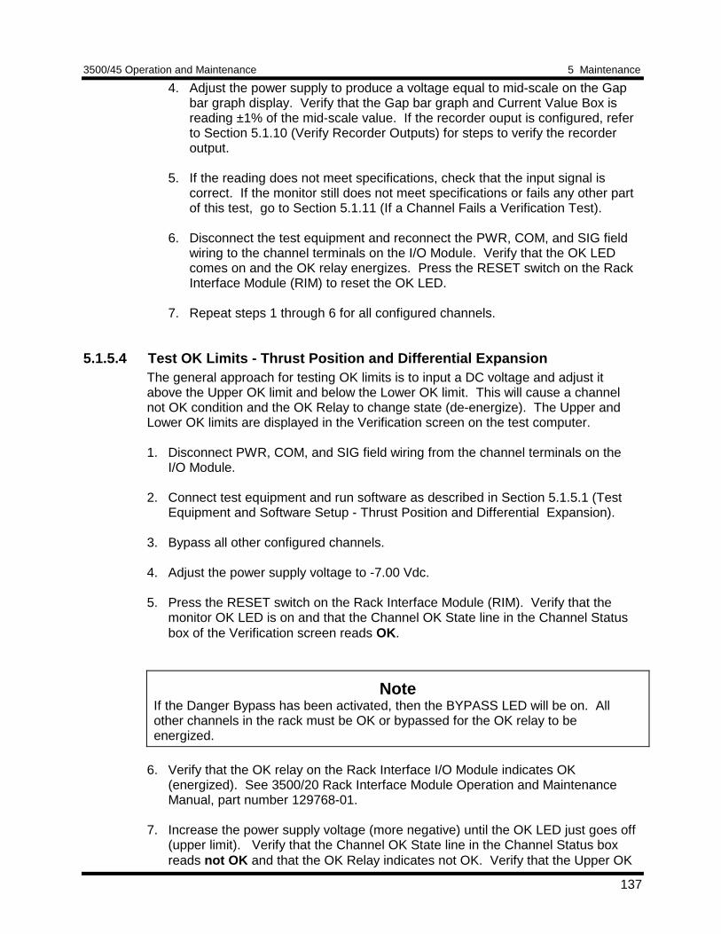
3500/45 Operation and Maintenance 5 Maintenance
137
4. Adjust the power supply to produce a voltage equal to mid-scale on the Gapbar graph display. Verify that the Gap bar graph and Current Value Box isreading ±1% of the mid-scale value. If the recorder ouput is configured, referto Section 5.1.10 (Verify Recorder Outputs) for steps to verify the recorderoutput.
5. If the reading does not meet specifications, check that the input signal is
correct. If the monitor still does not meet specifications or fails any other partof this test, go to Section 5.1.11 (If a Channel Fails a Verification Test).
6. Disconnect the test equipment and reconnect the PWR, COM, and SIG field
wiring to the channel terminals on the I/O Module. Verify that the OK LEDcomes on and the OK relay energizes. Press the RESET switch on the RackInterface Module (RIM) to reset the OK LED.
7. Repeat steps 1 through 6 for all configured channels.
5.1.5.4 Test OK Limits - Thrust Position and Differential ExpansionThe general approach for testing OK limits is to input a DC voltage and adjust itabove the Upper OK limit and below the Lower OK limit. This will cause a channelnot OK condition and the OK Relay to change state (de-energize). The Upper andLower OK limits are displayed in the Verification screen on the test computer.
1. Disconnect PWR, COM, and SIG field wiring from the channel terminals on theI/O Module.
2. Connect test equipment and run software as described in Section 5.1.5.1 (TestEquipment and Software Setup - Thrust Position and Differential Expansion).
3. Bypass all other configured channels. 4. Adjust the power supply voltage to -7.00 Vdc. 5. Press the RESET switch on the Rack Interface Module (RIM). Verify that the
monitor OK LED is on and that the Channel OK State line in the Channel Statusbox of the Verification screen reads OK.
NoteIf the Danger Bypass has been activated, then the BYPASS LED will be on. Allother channels in the rack must be OK or bypassed for the OK relay to beenergized.
6. Verify that the OK relay on the Rack Interface I/O Module indicates OK
(energized). See 3500/20 Rack Interface Module Operation and MaintenanceManual, part number 129768-01.
7. Increase the power supply voltage (more negative) until the OK LED just goes off
(upper limit). Verify that the Channel OK State line in the Channel Status boxreads not OK and that the OK Relay indicates not OK. Verify that the Upper OK
5 Maintenance 3500/45 Operation and Maintenance
138
limit voltage displayed on the Verification screen is equal to or more positive thanthe input voltage.
8. Decrease the power supply voltage (less negative) to -7.00 Vdc. 9. Press the RESET switch on the Rack Interface Module (RIM). Verify that the OK
LED comes back on, the OK relay energizes, and the Channel OK State line inthe Channel Status box reads OK.
10. Gradually decrease the power supply voltage (less negative) until the OK LED just
goes off (lower limit). Verify that the Channel OK State line in the Channel Statusbox reads not OK and that the OK Relay indicates not OK. Verify that the LowerOK limit voltage displayed on the Verification screen is equal to or more negativethan the input voltage.
11. Increase the power supply voltage (more negative) to -7.00 Vdc. 12. Press the RESET switch on the Rack Interface Module (RIM). Verify that the OK
LED comes back on, the OK relay energizes, and the Channel OK State line inthe Channel Status box reads OK.
13. If you cannot verify any configured OK limit, go to Section 5.1.11 (If a ChannelFails a Verification Test).
14. Disconnect the test equipment and reconnect the PWR, COM, and SIG field
wiring to the channel terminals on the I/O Module. Press the RESET switch onthe Rack Interface Module (RIM) and verify that the OK LED comes on and theOK relay energizes.
15. Repeat steps 1 through 14 for all configured channels. 16. Return the bypass switch for all configured channels to their original setting.
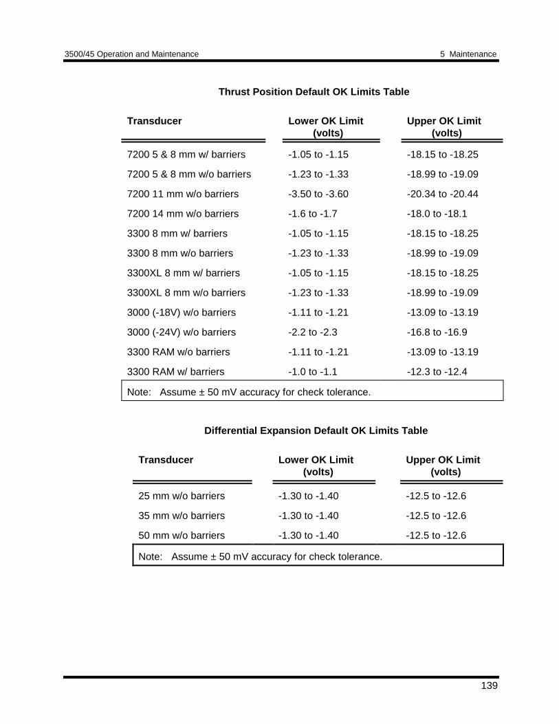
3500/45 Operation and Maintenance 5 Maintenance
139
Thrust Position Default OK Limits Table
Transducer Lower OK Limit(volts)
Upper OK Limit(volts)
7200 5 & 8 mm w/ barriers -1.05 to -1.15 -18.15 to -18.25
7200 5 & 8 mm w/o barriers -1.23 to -1.33 -18.99 to -19.09
7200 11 mm w/o barriers -3.50 to -3.60 -20.34 to -20.44
7200 14 mm w/o barriers -1.6 to -1.7 -18.0 to -18.1
3300 8 mm w/ barriers -1.05 to -1.15 -18.15 to -18.25
3300 8 mm w/o barriers -1.23 to -1.33 -18.99 to -19.09
3300XL 8 mm w/ barriers -1.05 to -1.15 -18.15 to -18.25
3300XL 8 mm w/o barriers -1.23 to -1.33 -18.99 to -19.09
3000 (-18V) w/o barriers -1.11 to -1.21 -13.09 to -13.19
3000 (-24V) w/o barriers -2.2 to -2.3 -16.8 to -16.9
3300 RAM w/o barriers -1.11 to -1.21 -13.09 to -13.19
3300 RAM w/ barriers -1.0 to -1.1 -12.3 to -12.4
Note: Assume ± 50 mV accuracy for check tolerance.
Differential Expansion Default OK Limits Table
Transducer Lower OK Limit(volts)
Upper OK Limit(volts)
25 mm w/o barriers -1.30 to -1.40 -12.5 to -12.6
35 mm w/o barriers -1.30 to -1.40 -12.5 to -12.6
50 mm w/o barriers -1.30 to -1.40 -12.5 to -12.6
Note: Assume ± 50 mV accuracy for check tolerance.
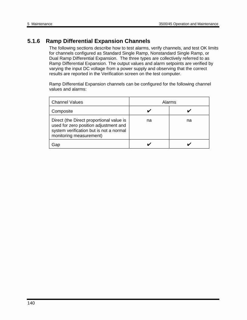
5 Maintenance 3500/45 Operation and Maintenance
140
5.1.6 Ramp Differential Expansion ChannelsThe following sections describe how to test alarms, verify channels, and test OK limitsfor channels configured as Standard Single Ramp, Nonstandard Single Ramp, orDual Ramp Differential Expansion. The three types are collectively referred to asRamp Differential Expansion. The output values and alarm setpoints are verified byvarying the input DC voltage from a power supply and observing that the correctresults are reported in the Verification screen on the test computer.
Ramp Differential Expansion channels can be configured for the following channelvalues and alarms:
Channel Values Alarms
Composite
Direct (the Direct proportional value isused for zero position adjustment andsystem verification but is not a normalmonitoring measurement)
na na
Gap
3500/45 Operation and Maintenance 5 Maintenance
141
5.1.6.1 Test Equipment and Software Setup - Ramp Differential ExpansionThe following test equipment and software setup can be used as the initial setupneeded for all the Ramp Differential Expansion channel verification procedures (TestAlarms, Verify Channels, and Test OK Limits).
WARNING
High voltage present.Contact could causeshock, burns, or death.
Do not touch exposedwires or terminals.
Application Alert
Tests will exceed alarmsetpoint levels causingalarms to activate. Thiscould result in a relaycontact state change.
Application Alert
Disconnecting fieldwiring will cause a notOK condition.
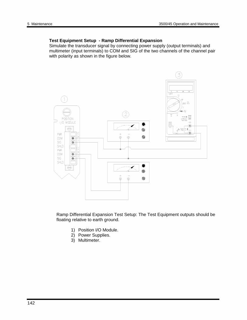
5 Maintenance 3500/45 Operation and Maintenance
142
Test Equipment Setup - Ramp Differential ExpansionSimulate the transducer signal by connecting power supply (output terminals) andmultimeter (input terminals) to COM and SIG of the two channels of the channel pairwith polarity as shown in the figure below.
Ramp Differential Expansion Test Setup: The Test Equipment outputs should befloating relative to earth ground.
1) Position I/O Module.2) Power Supplies.3) Multimeter.
3500/45 Operation and Maintenance 5 Maintenance
143
Verification Screen Setup - Ramp Differential ExpansionRun the Rack Configuration Software on the test computer. Choose SoftwareSwitches from the Utilities menu and choose the proper Slot number and Channelnumbers and enable channel switch number 5. Set the switch and Close . ChooseVerification from the Utilities menu and choose the proper Slot number and Channelnumber then click on the Verify button.
The following table directs you to the starting page of each maintenance sectionassociated with the Ramp Differential Expansion Channels.
SectionNumber
Topic PageNumber
5.1.6.2 Test Alarms - Composite 143
5.1.6.2 Test Alarms - Gap 143
5.1.6.3 Verify Channel Values -Composite/Direct
146
5.1.6.3 Verify Channel Values - Gap 146
5.1.6.4 Test OK Limits 154
5.1.6.2 Test Alarms - Ramp Differential ExpansionThe general approach for testing alarm setpoints is to simulate the Ramp DifferentialExpansion signals with a power supply. The alarm levels are tested by varying theDC voltage and observing that the correct results are reported in the Verificationscreen on the test computer. It is only necessary to test those alarm parameters thatare configured and being used. The general test procedure to verify current alarmoperation will include simulating transducer input signals and varying one or more ofthe signals:1. to exceed over Alert/Alarm 1 and Danger/Alarm 2 Setpoints and2. to drop below any under Alert/Alarm 1 and Danger/Alarm 2 Setpoints and3. to produce a nonalarm condition.
Composite
1. Disconnect PWR, COM, and SIG field wiring from the terminals of the two RampDifferential Expansion channels on the I/O Module.
2. Connect test equipment and run software as described in Section 5.1.6.1 (Test
Equipment and Software Setup - Ramp Differential Expansion). 3. Adjust the power supplies so that the Composite value is within the setpoint
levels. This can usually be done by setting the power supplies to the Direct zeroposition voltages for each channel of the channel pair. Note that the
5 Maintenance 3500/45 Operation and Maintenance
144
Direct zero position voltage is displayed over the Direct bar graph display in theVerification screen. You can check each channel of the channel pair by changingthe selected channel using the Channel dropdown list box in the Verificationscreen.
4. Press the RESET switch on the Rack Interface Module (RIM). Verify that the OKLED is on, the bar graph indicator for Composite is green, and the CompositeCurrent Value Box has no alarm indication.
5. Adjust the power supply voltages such that the signal just exceeds the Composite
Over Alert/Alarm 1 setpoint level. Wait for 2 or 3 seconds after the alarm timedelay expires and verify that the bar graph indicator for Composite changes colorfrom green to yellow.
6. Press the RESET switch on the Rack Interface Module (RIM). Verify that the bar
graph indicator for Composite remains yellow. 7. Adjust the power supply such that the signal just exceeds the Composite Over
Danger/Alarm 2 setpoint level. Wait for 2 or 3 seconds after the alarm time delayexpires and verify that the bar graph indicator for Composite changes color fromyellow to red.
8. Press the RESET switch on the Rack Interface Module (RIM). Verify that the bar
graph indicator for Composite remains red. 9. Adjust the power supply voltages such that the signal reads below the Over Alarm
setpoint levels. If the nonlatching option is configured, observe that the bar graphindicator for Composite changes color to green and that the Current Value Boxcontains no indication of alarms. Press the RESET switch on the Rack InterfaceModule (RIM) to reset latching alarms.
10. Repeat steps 3 through 9 to test the Under Alert/Alarm 1 and Under
Danger/Alarm 2 setpoints by adjusting the power supply to exceed the UnderAlarm setpoint levels.
11. If you cannot verify any configured alarm, recheck the configured setpoints. If the
monitor still does not alarm properly or fails any other part of this test, go toSection 5.1.11 (If a Channel Fails a Verification Test).
12. Disconnect the test equipment and reconnect the PWR, COM, and SIG field
wiring to the channel terminals on the I/O Module. Verify that the OK LED comeson and the OK relay energizes. Press the RESET switch on the Rack InterfaceModule (RIM) to reset the OK LED.
13. Repeat steps 1 through 12 for all configured Ramp Differential Expansion channel
pairs.
3500/45 Operation and Maintenance 5 Maintenance
145
14. Click on OK to close the Verification screen. Choose Software Switches fromthe Utilities menu. Select the proper slot and channels and disable channel switch5. Click on Set to download the new switch setting and then select Close to exit.
Gap
1. Disconnect PWR, COM, and SIG field wiring from the terminals of the two RampDifferential Expansion channels on the I/O Module.
2. Connect test equipment and run software as described in Section 5.1.6.1 (Test
Equipment and Software Setup - Ramp Differential Expansion). 3. Adjust the power supply to produce a voltage that is within the Gap setpoint levels
on the Gap bar graph display for the respective channel. 4. Press the RESET switch on the Rack Interface Module (RIM). Verify that the OK
LED is on, the bar graph indicator for Gap is green, and the Current Value Boxhas no alarm indication.
5. Adjust the power supply voltage such that the signal just exceeds the Gap Over
Alert/Alarm 1 setpoint level. Wait for 2 or 3 seconds until the alarm time delayexpires and verify that the bar graph indicator for Gap changes color from greento yellow.
6. Press the RESET switch on the Rack Interface Module (RIM). Verify that the bar
graph indicator for Gap remains yellow. 7. Adjust the power supply such that the signal just exceeds the Gap Over
Danger/Alarm 2 setpoint level. Wait for 2 or 3 seconds after the alarm time delayexpires and verify that the bar graph indicator for Gap changes color from yellowto red.
8. Press the RESET switch on the Rack Interface Module (RIM). Verify that the bar
graph indicator for Gap remains red. 9. Adjust the power supply voltage such that the signal reads below the Over Alarm
setpoint levels. If the nonlatching option is configured, observe that the bar graphindicator for Gap changes color to green and that the Current Value Box containsno indication of alarms. Press the RESET switch on the Rack Interface Module(RIM) to reset latching alarms.
10. Repeat steps 5 through 9 to test the Under Alert/Alarm 1 and Under
Danger/Alarm 2 setpoints by adjusting the power supply to exceed the UnderAlarm setpoint levels.
5 Maintenance 3500/45 Operation and Maintenance
146
11. If you cannot verify any configured alarm, recheck the configured setpoints. If themonitor still does not alarm properly or fails any other part of this test, go toSection 5.1.11 (If a Channel Fails a Verification Test).
12. Disconnect the test equipment and reconnect the PWR, COM, and SIG field
wiring to the channel terminals on the I/O Module. Verify that the OK LED comeson and the OK relay energizes. Press the RESET switch on the Rack InterfaceModule (RIM) to reset the OK LED.
13. Repeat steps 1 through 12 for the other channel of the Ramp Differential
Expansion channel pair and for other configured channels. 14. Click on OK to close the Verification screen. Choose Software Switches from
the Utilities menu. Select the proper slot and channels and disable channel switch5. Click on Set to download the new switch setting and then select Close to exit.
5.1.6.3 Verify Channel Values - Ramp Differential ExpansionThe general approach for testing these parameters is to simulate the transducersignals with a power supply on each channel of the channel pair. The output valuesare verified by changing the input DC voltage and observing that the correct resultsare reported in the Verification screen on the test computer.
Composite and Direct
The Composite proportional value is the differential expansion measurement which isof interest to an operator. It is calculated from the Direct proportional values from thetwo channels of the channel pair. The Direct value configuration parameters, such asfull-scale range, are automatically set by the Rack Configuration Software based onthe Composite full-scale range, ramp angle, and transducer types.
1. Disconnect PWR, COM, and SIG field wiring from the terminals of the two RampDifferential Expansion channels on the I/O Module.
2. Connect test equipment and run software as described in Section 5.1.6.1 (Test
Equipment and Software Setup - Ramp Differential Expansion).
3. Calculate the full-scale and bottom scale values using the formulas in the tablesshown in steps 3a for Standard Single Ramp DE, 3b for Nonstandard SingleRamp DE ,and 3c for Dual Ramp DE. The following abbreviations are used in thetables:
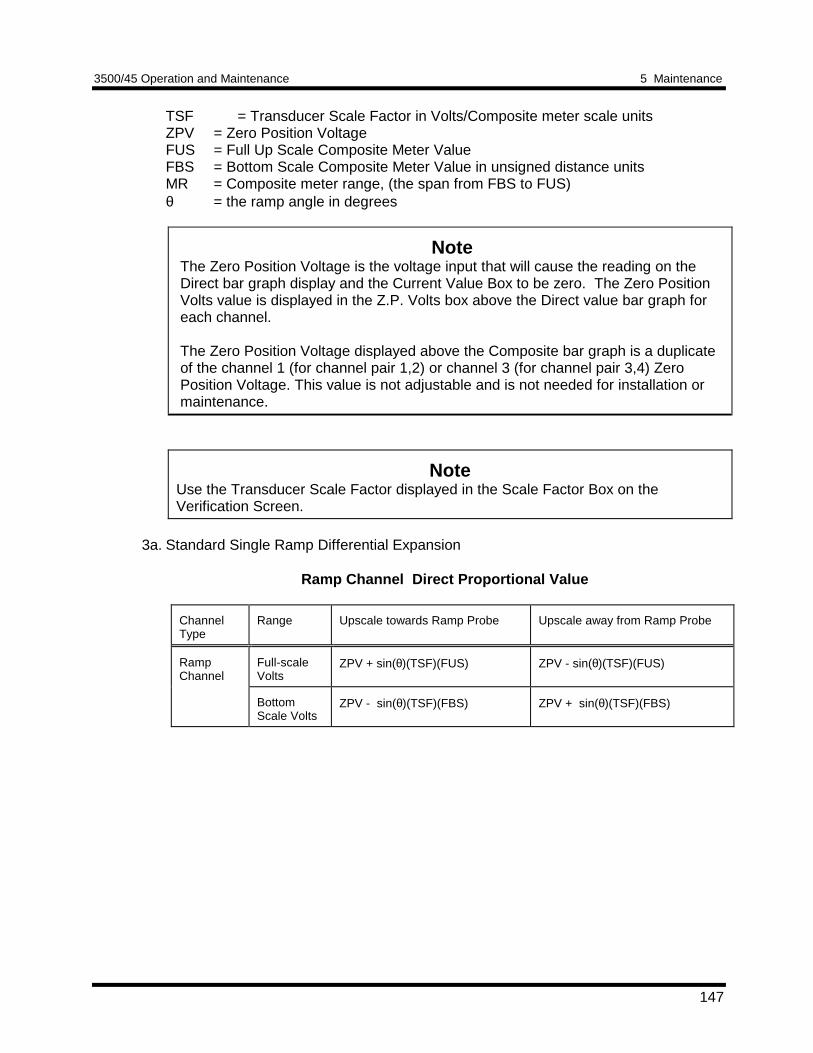
3500/45 Operation and Maintenance 5 Maintenance
147
TSF = Transducer Scale Factor in Volts/Composite meter scale unitsZPV = Zero Position VoltageFUS = Full Up Scale Composite Meter ValueFBS = Bottom Scale Composite Meter Value in unsigned distance unitsMR = Composite meter range, (the span from FBS to FUS)θ = the ramp angle in degrees
NoteThe Zero Position Voltage is the voltage input that will cause the reading on theDirect bar graph display and the Current Value Box to be zero. The Zero PositionVolts value is displayed in the Z.P. Volts box above the Direct value bar graph foreach channel.
The Zero Position Voltage displayed above the Composite bar graph is a duplicateof the channel 1 (for channel pair 1,2) or channel 3 (for channel pair 3,4) ZeroPosition Voltage. This value is not adjustable and is not needed for installation ormaintenance.
NoteUse the Transducer Scale Factor displayed in the Scale Factor Box on theVerification Screen.
3a. Standard Single Ramp Differential Expansion
Ramp Channel Direct Proportional Value
ChannelType
Range Upscale towards Ramp Probe Upscale away from Ramp Probe
RampChannel
Full-scaleVolts
ZPV + sin(θ)(TSF)(FUS) ZPV - sin(θ)(TSF)(FUS)
BottomScale Volts
ZPV - sin(θ)(TSF)(FBS) ZPV + sin(θ)(TSF)(FBS)
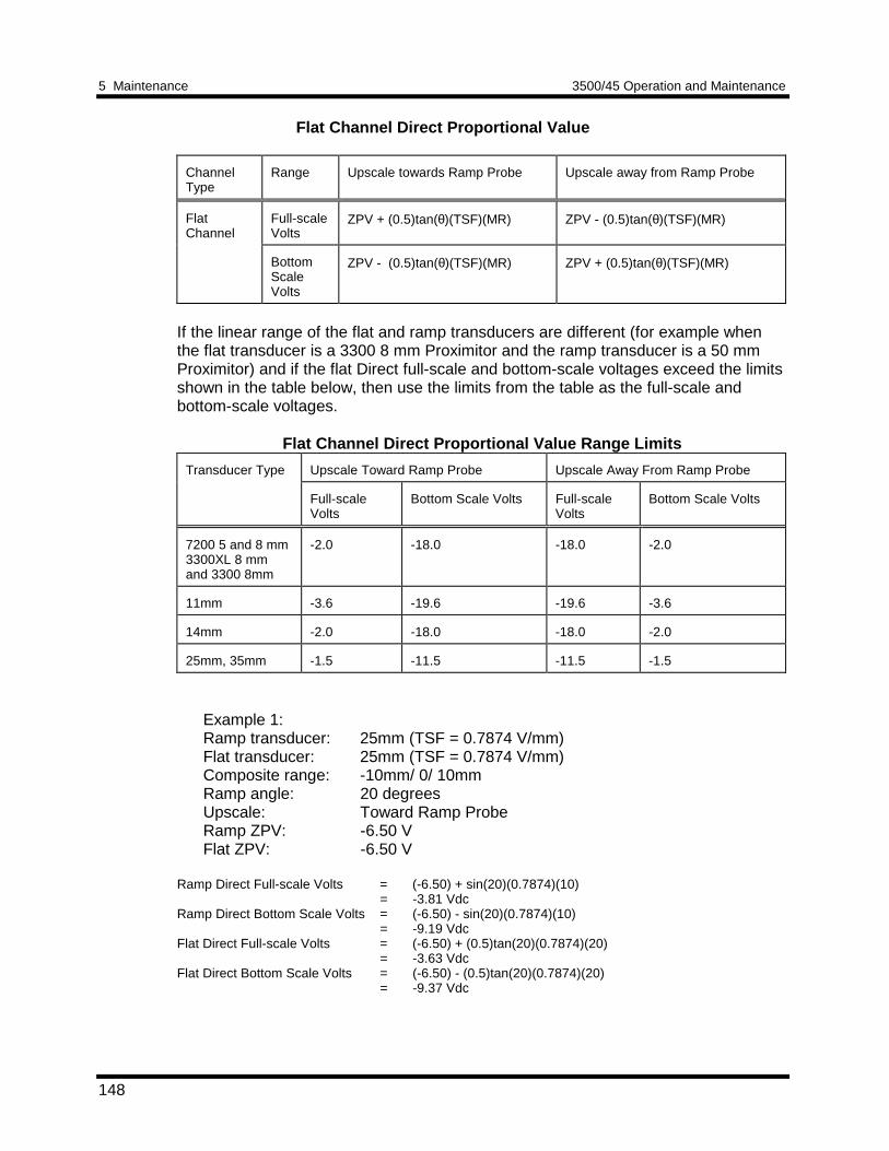
5 Maintenance 3500/45 Operation and Maintenance
148
Flat Channel Direct Proportional Value
ChannelType
Range Upscale towards Ramp Probe Upscale away from Ramp Probe
FlatChannel
Full-scaleVolts
ZPV + (0.5)tan(θ)(TSF)(MR) ZPV - (0.5)tan(θ)(TSF)(MR)
BottomScaleVolts
ZPV - (0.5)tan(θ)(TSF)(MR) ZPV + (0.5)tan(θ)(TSF)(MR)
If the linear range of the flat and ramp transducers are different (for example whenthe flat transducer is a 3300 8 mm Proximitor and the ramp transducer is a 50 mmProximitor) and if the flat Direct full-scale and bottom-scale voltages exceed the limitsshown in the table below, then use the limits from the table as the full-scale andbottom-scale voltages.
Flat Channel Direct Proportional Value Range Limits
Transducer Type Upscale Toward Ramp Probe Upscale Away From Ramp Probe
Full-scaleVolts
Bottom Scale Volts Full-scaleVolts
Bottom Scale Volts
7200 5 and 8 mm3300XL 8 mmand 3300 8mm
-2.0 -18.0 -18.0 -2.0
11mm -3.6 -19.6 -19.6 -3.6
14mm -2.0 -18.0 -18.0 -2.0
25mm, 35mm -1.5 -11.5 -11.5 -1.5
Example 1:Ramp transducer: 25mm (TSF = 0.7874 V/mm)Flat transducer: 25mm (TSF = 0.7874 V/mm)Composite range: -10mm/ 0/ 10mmRamp angle: 20 degreesUpscale: Toward Ramp ProbeRamp ZPV: -6.50 VFlat ZPV: -6.50 V
Ramp Direct Full-scale Volts = (-6.50) + sin(20)(0.7874)(10)= -3.81 Vdc
Ramp Direct Bottom Scale Volts = (-6.50) - sin(20)(0.7874)(10)= -9.19 Vdc
Flat Direct Full-scale Volts = (-6.50) + (0.5)tan(20)(0.7874)(20)= -3.63 Vdc
Flat Direct Bottom Scale Volts = (-6.50) - (0.5)tan(20)(0.7874)(20)= -9.37 Vdc
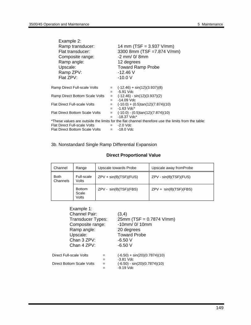
3500/45 Operation and Maintenance 5 Maintenance
149
Example 2:Ramp transducer: 14 mm (TSF = 3.937 V/mm)Flat transducer: 3300 8mm (TSF =7.874 V/mm)Composite range: -2 mm/ 0/ 8mmRamp angle: 12 degreesUpscale: Toward Ramp ProbeRamp ZPV: -12.46 VFlat ZPV: -10.0 V
Ramp Direct Full-scale Volts = (-12.46) + sin(12)(3.937)(8)= -5.91 Vdc
Ramp Direct Bottom Scale Volts = (-12.46) - sin(12)(3.937)(2)= -14.09 Vdc
Flat Direct Full-scale Volts = (-10.0) + (0.5)tan(12)(7.874)(10)= -1.63 Vdc*
Flat Direct Bottom Scale Volts = (-10.0) - (0.5)tan(12)(7.874)(10)= -18.37 Vdc*
*These values are outside the limits for the flat channel therefore use the limits from the table:Flat Direct Full-scale Volts = -2.0 VdcFlat Direct Bottom Scale Volts = -18.0 Vdc
3b. Nonstandard Single Ramp Differential Expansion
Direct Proportional Value
Channel Range Upscale towards Probe Upscale away fromProbe
BothChannels
Full-scaleVolts
ZPV + sin(θ)(TSF)(FUS) ZPV - sin(θ)(TSF)(FUS)
BottomScaleVolts
ZPV - sin(θ)(TSF)(FBS) ZPV + sin(θ)(TSF)(FBS)
Example 1:Channel Pair: (3,4)Transducer Types: 25mm (TSF = 0.7874 V/mm)Composite range: -10mm/ 0/ 10mmRamp angle: 20 degreesUpscale: Toward ProbeChan 3 ZPV: -6.50 VChan 4 ZPV: -6.50 V
Direct Full-scale Volts = (-6.50) + sin(20)(0.7874)(10)= -3.81 Vdc
Direct Bottom Scale Volts = (-6.50) - sin(20)(0.7874)(10)= -9.19 Vdc
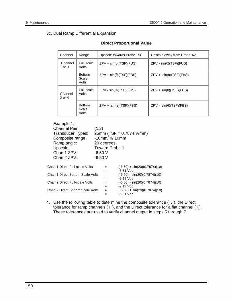
5 Maintenance 3500/45 Operation and Maintenance
150
3c. Dual Ramp Differential Expansion
Direct Proportional Value
Channel Range Upscale towards Probe 1/3 Upscale away from Probe 1/3
Channel1 or 3
Full-scaleVolts
ZPV + sin(θ)(TSF)(FUS) ZPV - sin(θ)(TSF)(FUS)
BottomScaleVolts
ZPV - sin(θ)(TSF)(FBS) ZPV + sin(θ)(TSF)(FBS)
Channel2 or 4
Full-scaleVolts
ZPV - sin(θ)(TSF)(FUS) ZPV + sin(θ)(TSF)(FUS)
BottomScaleVolts
ZPV + sin(θ)(TSF)(FBS) ZPV - sin(θ)(TSF)(FBS)
Example 1:Channel Pair: (1,2)Transducer Types: 25mm (TSF = 0.7874 V/mm)Composite range: -10mm/ 0/ 10mmRamp angle: 20 degreesUpscale: Toward Probe 1Chan 1 ZPV: -6.50 VChan 2 ZPV: -6.50 V
Chan 1 Direct Full-scale Volts = (-6.50) + sin(20)(0.7874)(10)= -3.81 Vdc
Chan 1 Direct Bottom Scale Volts = (-6.50) - sin(20)(0.7874)(10)= -9.19 Vdc
Chan 2 Direct Full-scale Volts = (-6.50) - sin(20)(0.7874)(10)= -9.19 Vdc
Chan 2 Direct Bottom Scale Volts = (-6.50) + sin(20)(0.7874)(10)= -3.81 Vdc
4. Use the following table to determine the composite tolerance (Tc ), the Directtolerance for ramp channels (Tr ), and the Direct tolerance for a flat channel (Tf).These tolerances are used to verify channel output in steps 5 through 7.
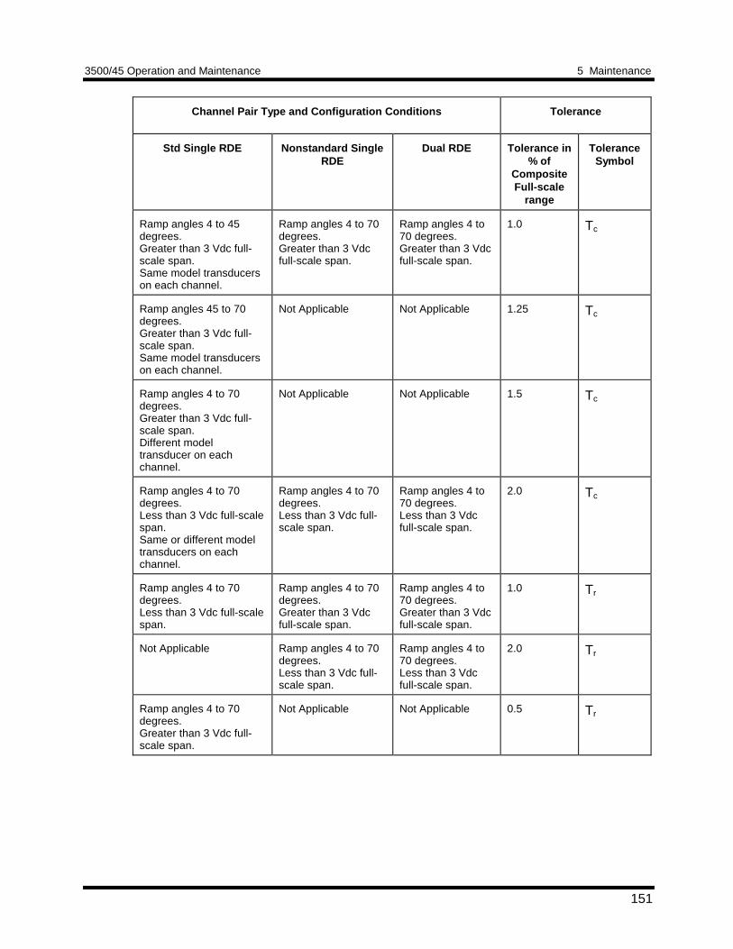
3500/45 Operation and Maintenance 5 Maintenance
151
Channel Pair Type and Configuration Conditions Tolerance
Std Single RDE Nonstandard SingleRDE
Dual RDE Tolerance in% of
CompositeFull-scale
range
ToleranceSymbol
Ramp angles 4 to 45degrees.Greater than 3 Vdc full-scale span.Same model transducerson each channel.
Ramp angles 4 to 70degrees.Greater than 3 Vdcfull-scale span.
Ramp angles 4 to70 degrees.Greater than 3 Vdcfull-scale span.
1.0 Tc
Ramp angles 45 to 70degrees.Greater than 3 Vdc full-scale span.Same model transducerson each channel.
Not Applicable Not Applicable 1.25 Tc
Ramp angles 4 to 70degrees.Greater than 3 Vdc full-scale span.Different modeltransducer on eachchannel.
Not Applicable Not Applicable 1.5 Tc
Ramp angles 4 to 70degrees.Less than 3 Vdc full-scalespan.Same or different modeltransducers on eachchannel.
Ramp angles 4 to 70degrees.Less than 3 Vdc full-scale span.
Ramp angles 4 to70 degrees.Less than 3 Vdcfull-scale span.
2.0 Tc
Ramp angles 4 to 70degrees.Less than 3 Vdc full-scalespan.
Ramp angles 4 to 70degrees.Greater than 3 Vdcfull-scale span.
Ramp angles 4 to70 degrees.Greater than 3 Vdcfull-scale span.
1.0 Tr
Not Applicable Ramp angles 4 to 70degrees.Less than 3 Vdc full-scale span.
Ramp angles 4 to70 degrees.Less than 3 Vdcfull-scale span.
2.0 Tr
Ramp angles 4 to 70degrees.Greater than 3 Vdc full-scale span.
Not Applicable Not Applicable 0.5 Tr
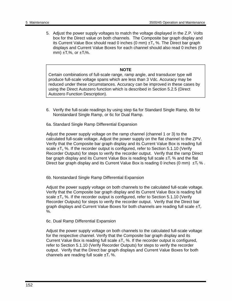
5 Maintenance 3500/45 Operation and Maintenance
152
5. Adjust the power supply voltages to match the voltage displayed in the Z.P. Voltsbox for the Direct value on both channels. The Composite bar graph display andits Current Value Box should read 0 inches (0 mm) ±Tc %. The Direct bar graphdisplays and Current Value Boxes for each channel should also read 0 inches (0mm) ±Tr%, or ±Tf%.
NOTECertain combinations of full-scale range, ramp angle, and transducer type willproduce full-scale voltage spans which are less than 3 Vdc. Accuracy may bereduced under these circumstances. Accuracy can be improved in these cases byusing the Direct Autozero function which is described in Section 5.2.5 (DirectAutozero Function Description).
6. Verify the full-scale readings by using step 6a for Standard Single Ramp, 6b forNonstandard Single Ramp, or 6c for Dual Ramp.
6a. Standard Single Ramp Differential Expansion
Adjust the power supply voltage on the ramp channel (channel 1 or 3) to thecalculated full-scale voltage. Adjust the power supply on the flat channel to the ZPV.Verify that the Composite bar graph display and its Current Value Box is reading fullscale ±Tc %. If the recorder output is configured, refer to Section 5.1.10 (VerifyRecorder Outputs) for steps to verify the recorder output. Verify that the ramp Directbar graph display and its Current Value Box is reading full scale ±Tr % and the flatDirect bar graph display and its Current Value Box is reading 0 inches (0 mm) ±Tf % .
6b. Nonstandard Single Ramp Differential Expansion
Adjust the power supply voltage on both channels to the calculated full-scale voltage.Verify that the Composite bar graph display and its Current Value Box is reading fullscale ±Tc %. If the recorder output is configured, refer to Section 5.1.10 (VerifyRecorder Outputs) for steps to verify the recorder output. Verify that the Direct bargraph displays and Current Value Boxes for both channels are reading full scale ±Tr
%.
6c. Dual Ramp Differential Expansion
Adjust the power supply voltage on both channels to the calculated full-scale voltagefor the respective channel. Verify that the Composite bar graph display and itsCurrent Value Box is reading full scale ±Tc %. If the recorder output is configured,refer to Section 5.1.10 (Verify Recorder Outputs) for steps to verify the recorderoutput. Verify that the Direct bar graph displays and Current Value Boxes for bothchannels are reading full scale ±Tr %.
3500/45 Operation and Maintenance 5 Maintenance
153
7. Verify the bottom scale readings using step 7a for Standard Single Ramp, 7b forNonstandard Single Ramp, or 7c for Dual Ramp.
7a. Standard Single Ramp Differential Expansion
Adjust the power supply voltage on the ramp channel (channel 1 or 3) to thecalculated bottom-scale voltage. Adjust the power supply on the flat channel to theZPV. Verify that the Composite bar graph display and its Current Value Box is readingbottom scale ±Tc %. If the recorder output is configured, refer to Section 5.1.10(Verify Recorder Outputs) for steps to verify the recorder output. Verify that the rampDirect bar graph display and its Current Value Box is reading bottom scale ±Tr % andthe flat Direct bar graph display and its Current Value Box is reading 0 inches (0 mm)±Tf % .
7b. Nonstandard Single Ramp Differential Expansion
Adjust the power supply voltage on both channels to the calculated bottom-scalevoltage. Verify that the Composite bar graph display and its Current Value Box isreading bottom scale ±Tc %. If the recorder output is configured, refer to Section5.1.10 (Verify Recorder Outputs) for steps to verify the recorder output. Verify thatthe Direct bar graph displays and Current Value Boxes for both channels are readingbottom scale ±Tr %.
7c. Dual Ramp Differential Expansion
Adjust the power supply voltage on both channels to the calculated bottom-scalevoltage for the respective channel. Verify that the Composite bar graph display and itsCurrent Value Box is reading bottom scale ±Tc %. If the recorder output is configured,refer to Section 5.1.10 (Verify Recorder Outputs) for steps to verify the recorderoutput. Verify that the Direct bar graph displays and Current Value Boxes for bothchannels are reading bottom scale ±Tr %.
8. If the reading does not meet specifications, check that the input signal is correctand that the monitor is correctly configured. If the monitor still does not meetspecifications or fails any other part of this test, go to Section 5.1.11 (If a ChannelFails a Verification Test).
9. Disconnect the test equipment and reconnect the PWR, COM, and SIG field
wiring to the channel terminals on the I/O Module. Verify that the OK LED comeson and the OK relay energizes. Press the RESET switch on the Rack InterfaceModule (RIM) to reset the OK LED.
10. Repeat steps 1 through 9 for all configured channel pairs. 11. Click on OK to close the Verification screen. Choose Software Switches from
the Utilities menu. Select the proper slot and channels and disable channel switch5. Click on Set to download the new switch setting and then select Close to exit.
5 Maintenance 3500/45 Operation and Maintenance
154
Gap
1. Disconnect PWR, COM, and SIG field wiring from the channel terminals on theI/O Module.
2. Connect test equipment and run software as described in Section 5.1.6.1 (Test
Equipment and Software Setup - Ramp Differential Expansion). 3. Adjust the power supply to produce a voltage equal to -18.00 Vdc on the Gap bar
graph display. Verify that the Gap bar graph display and the Current Value Box isreading ±1% of -18.00 Vdc.
4. Adjust the power supply to produce a voltage equal to mid-scale on the Gap bar
graph display. Verify that the Gap bar graph and Current Value Box is reading±1% of the mid-scale value.
5. If the reading does not meet specifications, check that the input signal is correct.
If the monitor still does not meet specifications or fails any other part of this test,go to Section 5.1.11 (If a Channel Fails a Verification Test).
6. Disconnect the test equipment and reconnect the PWR, COM, and SIG field
wiring to the channel terminals on the I/O Module. Verify that the OK LED comeson and the OK relay energizes. Press the RESET switch on the Rack InterfaceModule (RIM) to reset the OK LED.
7. Repeat steps 1 through 6 for all configured channels. 8. Click on OK to close the Verification screen. Choose Software Switches from
the Utilities menu. Select the proper slot and channels and disable channel switch5. Click on Set to download the new switch setting and then select Close to exit.
5.1.6.4 Test OK Limits - Ramp Differential ExpansionThe general approach for testing OK limits is to input a DC voltage and adjust itabove the Upper OK limit and below the Lower OK limit. This will cause a channelnot OK condition and the OK Relay to change state (de-energize). The Upper andLower OK limits are displayed in the Verification screen on the test computer. Thetable on page 156 lists the default OK limits for common transducers.
1. Disconnect PWR, COM, and SIG field wiring from the channel terminals on theI/O Module from both channels of the channel pair.
2. Connect test equipment and run software as described in Section 5.1.6.1 (Test
Equipment and Software Setup - Ramp Differential Expansion). Connect to bothchannels.
3. Verify that All other channels in the rack are OK or Bypassed. Bypass all
channels that are not OK by using the channel switches dialog in the RackConfiguration Software. Switch settings take effect when you download theconfiguration.
4. Adjust the power supply voltage to -7.00 Vdc.
3500/45 Operation and Maintenance 5 Maintenance
155
5. Press the RESET switch on the Rack Interface Module (RIM). Verify that the
monitor OK LED is on and that the Channel OK State line in the Channel Statusbox of the Verification screen reads OK.
NoteIf the Danger Bypass has been activated, then the BYPASS LED will be on. Allother channels in the rack must be OK or bypassed for the OK relay to beenergized.
6. Verify that the OK relay on the Rack Interface I/O Module indicates OK
(energized). See 3500/20 Rack Interface Module Operation and MaintenanceManual, part number 129768-01.
7. Increase the power supply voltage (more negative) until the OK LED just goes off
(upper limit). Verify that the Channel OK State line in the Channel Status boxreads not OK and that the OK Relay indicates not OK. Verify that the Upper OKlimit voltage displayed on the Verification screen is equal to or more positive thanthe input voltage.
8. Decrease the power supply voltage (less negative) to -7.00 Vdc. 9. Press the RESET switch on the Rack Interface Module (RIM). Verify that the OK
LED comes back on, the OK relay energizes, and the Channel OK State line inthe Channel Status box reads OK.
10. Gradually decrease the power supply voltage (less negative) until the OK LED just
goes off (lower limit). Verify that the Channel OK State line in the Channel Statusbox reads not OK and that the OK Relay indicates not OK. Verify that the LowerOK limit voltage displayed on the Verification screen is equal to or more negativethan the input voltage.
11. Increase the power supply voltage (more negative) to -7.00 Vdc. 12. Press the RESET switch on the Rack Interface Module (RIM). Verify that the OK
LED comes back on, the OK relay energizes, and the Channel OK State line inthe Channel Status box reads OK.
13. If you cannot verify any configured OK limit, go to Section 5.1.11 (If a Channel
Fails a Verification Test). 14. Repeat steps 2 through 13 for the other channel of the channel pair. 15. Disconnect the test equipment and reconnect the PWR, COM, and SIG field
wiring to the channel terminals on the I/O module. Press the RESET switch onthe Rack Interface Module (RIM) and verify that the OK LED comes on and theOK relay energizes
16. Repeat steps 1 through 15 for all configured channel pairs.
5 Maintenance 3500/45 Operation and Maintenance
156
17. Return the bypass switch for all configured channels to their original setting. 18. Click on OK to close the Verification screen. Choose Software Switches from
the Utilities menu. Select the proper slot and channels and disable channel switch5. Click on Set to download the new switch setting then select Close to exit.
Ramp Differential Expansion Default OK Limits Table
Transducer Lower OK Limit(volts)
Upper OK Limit(volts)
7200 5 & 8 mm w/o barriers -1.23 to -1.33 -18.99 to -19.09
3300XL 8 mm w/o barriers -1.23 to -1.33 -18.99 to -19.09
3300 8 mm w/o barriers -1.23 to -1.33 -18.99 to -19.09
7200 11 mm w/o barriers -3.50 to -3.60 -20.34 to -20.44
7200 14 mm w/o barriers3300 16mm HTPS w/o barriers
-1.6 to -1.7-1.6 to -1.7
-18.0 to -18.1-18.0 to -18.1
25 mm w/o barriers -1.30 to -1.40 -12.5 to -12.6
35 mm w/o barriers -1.30 to -1.40 -12.5 to -12.6
50 mm w/o barriers -1.30 to -1.40 -12.5 to -12.6
50mm DE w/o barriers -1.30 to - 1.40 -13.35 to - 13.45
Note: Assume ± 50 mV accuracy for check tolerance.
5.1.7 Complementary Input Differential Expansion ChannelsThe following sections describe how to test alarms, verify channels, and test OK limitsfor channels configured as Complementary Input Differential Expansion (CIDE). Theoutput values and alarm setpoints are verified by varying the input DC voltage from apower supply and observing that the correct results are reported in the Verificationscreen on the test computer.
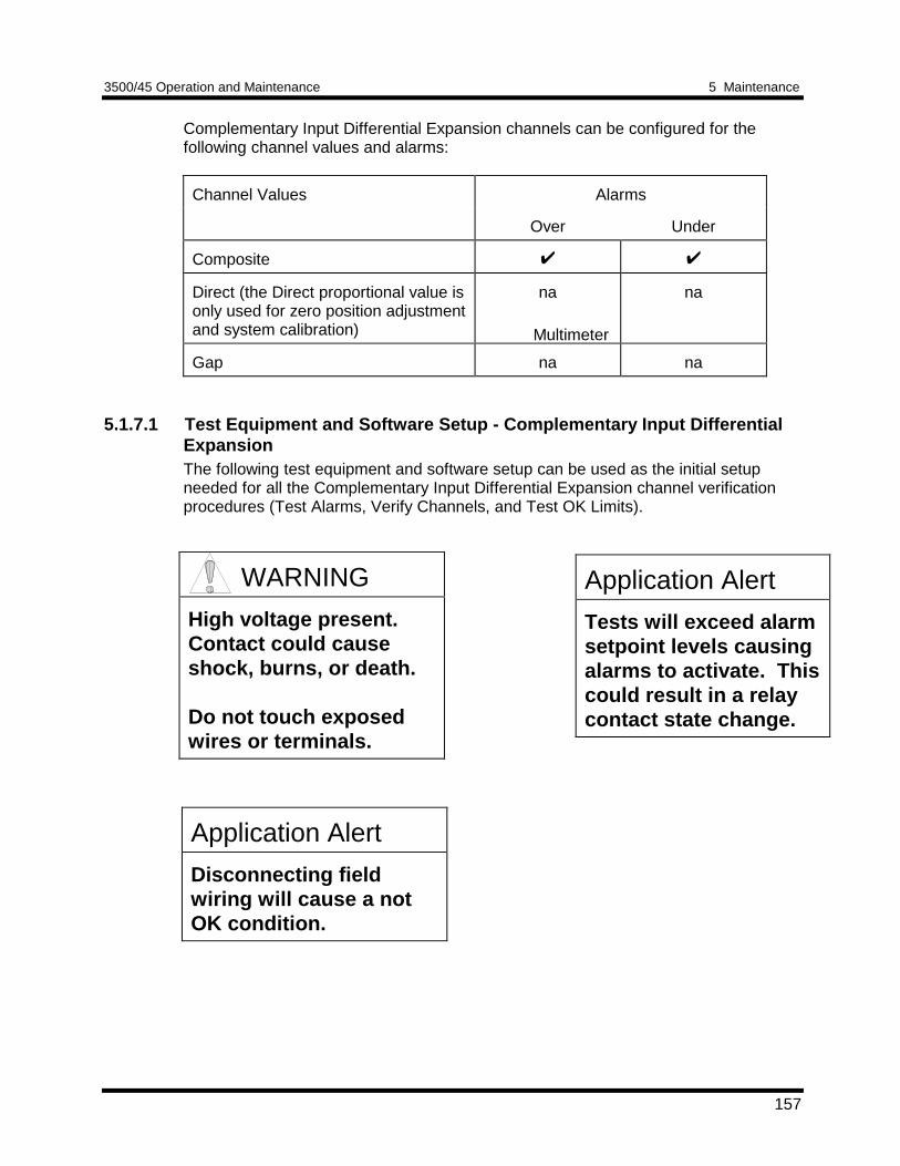
3500/45 Operation and Maintenance 5 Maintenance
157
Complementary Input Differential Expansion channels can be configured for thefollowing channel values and alarms:
Channel Values Alarms
Over Under
Composite
Direct (the Direct proportional value isonly used for zero position adjustmentand system calibration)
na na
Gap na na
5.1.7.1 Test Equipment and Software Setup - Complementary Input DifferentialExpansionThe following test equipment and software setup can be used as the initial setupneeded for all the Complementary Input Differential Expansion channel verificationprocedures (Test Alarms, Verify Channels, and Test OK Limits).
Application Alert
Tests will exceed alarmsetpoint levels causingalarms to activate. Thiscould result in a relaycontact state change.
Application Alert
Disconnecting fieldwiring will cause a notOK condition.
WARNING
High voltage present.Contact could causeshock, burns, or death.
Do not touch exposedwires or terminals.
Multimeter
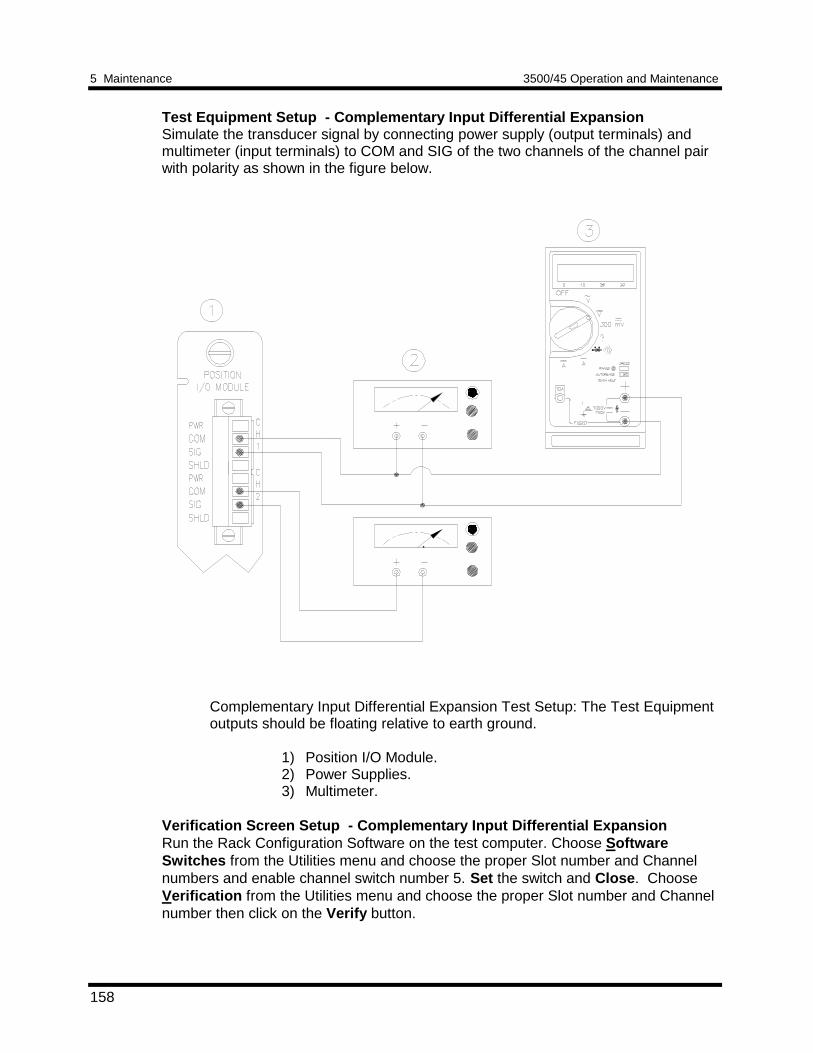
5 Maintenance 3500/45 Operation and Maintenance
158
Test Equipment Setup - Complementary Input Differential ExpansionSimulate the transducer signal by connecting power supply (output terminals) andmultimeter (input terminals) to COM and SIG of the two channels of the channel pairwith polarity as shown in the figure below.
Complementary Input Differential Expansion Test Setup: The Test Equipmentoutputs should be floating relative to earth ground.
1) Position I/O Module.2) Power Supplies.3) Multimeter.
Verification Screen Setup - Complementary Input Differential ExpansionRun the Rack Configuration Software on the test computer. Choose SoftwareSwitches from the Utilities menu and choose the proper Slot number and Channelnumbers and enable channel switch number 5. Set the switch and Close . ChooseVerification from the Utilities menu and choose the proper Slot number and Channelnumber then click on the Verify button.
3500/45 Operation and Maintenance 5 Maintenance
159
The following table directs you to the starting page of each maintenance sectionassociated with the Complementary Input Differential Expansion Channels.
SectionNumber
Topic PageNumber
5.1.7.2 Test Alarms - Composite 159
5.1.7.3 Verify Channel Values - Composite/Direct 160
5.1.7.4 Test OK Limits 164
5.1.7.2 Test Alarms - Complementary Input Differential ExpansionThe general approach for testing alarm setpoints is to simulate the ComplementaryInput Differential Expansion signals with a power supply. The alarm levels are testedby varying the DC voltage and observing that the correct results are reported in theVerification screen on the test computer. It is only necessary to test those alarmparameters that are configured and being used. The general test procedure to verifycurrent alarm operation will include simulating transducer input signals and varyingone or more of the signals:
1. to exceed over Alert/Alarm 1 and Danger/Alarm 2 Setpoints2. to drop below any under Alert/Alarm 1 and Danger/Alarm 2 Setpoints3. to produce a nonalarm condition
Composite
1. Disconnect PWR, COM, and SIG field wiring from the terminals of the two CIDEchannels on the I/O Module.
2. Connect test equipment and run software as described in Section 5.1.7.1 (Test
Equipment and Software Setup - Complementary Input Differential Expansion). 3. Adjust the power supplies so that the Composite value is within the setpoint
levels. This can usually be done by setting the power supplies to the cross overvoltages for each channel of the channel pair. Note that the cross over voltage isdisplayed over the Direct bar graph display in the Verification screen for eachchannel. You can check each channel of the channel pair by changing theselected channel using the Channel dropdown list box in the Verification screen.
4. Press the RESET switch on the Rack Interface Module (RIM). Verify that the OKLED is on, the bar graph indicator for Composite is green, and the CompositeCurrent Value Box has no alarm indication.
5. Adjust the power supply voltages such that the signal just exceeds the CompositeOver Alert/Alarm 1 setpoint level. Wait for 2 or 3 seconds after the alarm timedelay expires and verify that the bar graph indicator for Composite changes colorfrom green to yellow.
5 Maintenance 3500/45 Operation and Maintenance
160
6. Press the RESET switch on the Rack Interface Module (RIM). Verify that the bargraph indicator for Composite remains yellow.
7. Adjust the power supply such that the signal just exceeds the Composite Over
Danger/Alarm 2 setpoint level. Wait for 2 or 3 seconds after the alarm time delayexpires and verify that the bar graph indicator for Composite changes color fromyellow to red.
8. Press the RESET switch on the Rack Interface Module (RIM). Verify that the bar
graph indicator for Composite remains red. 9. Adjust the power supply voltages such that the signal reads below the Over Alarm
setpoint levels. If the nonlatching option is configured, observe that the bar graphindicator for Composite changes color to green and that the Current Value Boxcontains no indication of alarms. Press the RESET switch on the Rack InterfaceModule (RIM) to reset latching alarms.
10. Repeat steps 3 through 9 to test the Under Alert/Alarm 1 and Under
Danger/Alarm 2 setpoints by adjusting the power supply to exceed the UnderAlarm setpoint levels.
11. If you cannot verify any configured alarm, recheck the configured setpoints. If the
monitor still does not alarm properly or fails any other part of this test, go toSection 5.1.11 (If a Channel Fails a Verification Test).
12. Disconnect the test equipment and reconnect the PWR, COM, and SIG field
wiring to the channel terminals on the I/O Module. Verify that the OK LED comeson and the OK relay energizes. Press the RESET switch on the Rack InterfaceModule (RIM) to reset the OK LED.
13. Repeat steps 1 through 12 for all configured Complementary Input Differential
Expansion channel pairs. 14. Click on OK to close the Verification screen. Choose Software Switches from
the Utilities menu. Select the proper slot and channels and disable channel switch5. Click on Set to download the new switch setting and then select Close to exit.
5.1.7.3 Verify Channel Values - Complementary Input Differential ExpansionThe general approach for testing these parameters is to simulate the transducersignals with a power supply on each channel of the channel pair. The output valuesare verified by changing the input DC voltage and observing that the correct resultsare reported in the Verification screen on the test computer.
Composite and Direct
The Composite proportional value is the differential expansion measurement which isof interest to an operator. It is calculated from the Direct proportional values of thetwo channels of the channel pair. The Direct value configuration parameters, such asfull-scale range and zero position voltage are automatically set by the Rack
3500/45 Operation and Maintenance 5 Maintenance
161
Configuration Software based on the Composite full-scale range, cross over voltage,and transducer type.
1. Disconnect PWR, COM, and SIG field wiring from the terminals of the two CIDEchannels on the I/O Module.
2. Connect test equipment and run software as described in Section 5.1.7.1 (Test
Equipment and Software Setup - Complementary Input Differential Expansion). 3. Calculate the full-scale and bottom scale values using the formulas below. The
following abbreviations are used:
TSF = Transducer Scale Factor in Volts/Composite meter scale unitsCOV = Cross Over VoltageMR = Composite meter range, (the span from composite bottom scale value
to the composite full-scale value)
NoteThe Cross Over Voltage is the voltage input that will cause the reading on theDirect bar graph display and Current Value Box to be zero. The Cross OverVoltage is displayed in the COV box above the Direct value bar graph for eachchannel of the channel pair. When both channels are at the COV, theComposite bar graph display and Current Value Box should indicate midscale(for example, if the scale is 4 mm - 0 - 16 mm, a reading of 6 mm is midscale).
A value is also displayed in the Composite COV box above the Composite bargraph. This value is not adjustable and is not used for any installation ormaintenance operation.
5 Maintenance 3500/45 Operation and Maintenance
162
NoteUse the Transducer Scale Factor displayed in the Scale Factor Box on theVerification Screen for the appropriate channel when using the formulasbelow.
CIDE Direct Full Scale and Bottom Scale
Direct Full Scale = COV + (0.5)(TSF)(MR)
Direct Bottom Scale = COV
Use the above formulas for both channels of the channel pair. Note that you must usethe correct COV and TSF for the channel.
Example 1:
Channel pair: (1,2)Transducer type: 35 mm(scale factor 20 mV/mil or 20 V/inch)Composite full scale: 0.5 inch - 0 - 0.5 inchChannel 1 COV: -11.6Channel 2 COV: -11.8Upscale Direction: Towards Probe 1
Channel 1 Direct Bottom Scale = -11.6 VdcChannel 1 Direct Full Scale = (-11.6) + (0.5)(20 V/inch)(1 inch)
= -1.6 VdcChannel 2 Direct Bottom Scale = -11.8 VdcChannel 2 Direct Full Scale = (-11.8) + (0.5)(20 V/inch)(1 inch)
= -1.8 VdcComposite Full Scale = Channel 1 Direct Full Scale, with Channel
2 more negative than its COVComposite Bottom Scale = Channel 2 Direct Full Scale, with Channel
1 more negative than its COV
3500/45 Operation and Maintenance 5 Maintenance
163
Example 2:Channel pair: (3,4)Transducer type: 50 mm DE (scale factor 10 mV/mil or 0.3937V/mm
on channel 3 and 0.4055 V/mm on channel 4)Composite full scale: 10mm - 0 - 40mmChannel 3 COV: -11.64Channel 4 COV: -11.94Upscale Direction: Away from Probe 3
Channel 3 Direct Bottom Scale = -11.64 VdcChannel 3 Direct Full Scale = (-11.64) +
(0.5)(0.3937 V/mm)(50 mm)= -1.8 Vdc
Channel 4 Direct Bottom Scale = -11.94 VdcChannel 4 Direct Full Scale = (-11.94) +
(0.5)(0.4055 V/mm)(50 mm)= -1.8 Vdc
Composite Full Scale = Channel 4 Direct Full Scale, channel 3more negative than its COV
Composite Bottom Scale = Channel 3 Direct Full Scale, channel 4more negative than its COV
4. Adjust the power supply voltages to match the Cross Over Voltage displayed inthe COV box above the Direct bar graph for each channel. Verify that the Directbar graph display and the Current Value Box is reading 0 inches (0 mm) ±1% forboth channels of the channel pair. Verify that the Composite bar graph displayand Current Value Box is reading midscale ±1%.
5. Determine which channel is the upscale channel. On the upscale channel adjust
the power supply voltage to the Direct full-scale value calculated for that channel.Adjust the power supply on the other channel to be more negative than its COV.Verify that the Composite bar graph display and Current Value Box is reading fullscale ±1%. If the recorder is configured, refer to Section 5.1.10 (Verify RecorderOutputs) for steps to verify the recorder output.
6. Determine which channel is the downscale channel. On the downscale channel
adjust the power supply voltage to the Direct full-scale value calculated for thatchannel. Adjust the power supply on the other channel to be more negative thanits COV. Verify that the Composite bar graph display and Current Value Box isreading bottom scale ±1%. If the recorder is configured, refer to Section 5.1.10(Verify Recorder Outputs) for steps to verify the recorder output.
7. If the reading does not meet specifications, check that the input signal is correctand that the monitor is correctly configured. If the monitor still does not meetspecifications or fails any other part of this test, go to Section 5.1.11 (If a ChannelFails a Verification Test).
5 Maintenance 3500/45 Operation and Maintenance
164
8. Disconnect the test equipment and reconnect the PWR, COM, and SIG fieldwiring to the channel terminals on the I/O Module. Verify that the OK LED comeson and the OK relay energizes. Press the RESET switch on the Rack InterfaceModule (RIM) to reset the OK LED.
9. Repeat steps 1 through 8 for all configured channel pairs. 10. Click on OK to close the Verification screen. Choose Software Switches from
the Utilities menu. Select the proper slot and channels and disable channel switch5. Click on Set to download the new switch setting and then select Close to exit.
5.1.7.4 Test OK Limits - Complementary Input Differential ExpansionThe general approach for testing OK limits is to input a DC voltage into both channelsof the channel pair and adjust the voltages above the Upper OK limit and below theLower OK limit. This will cause a channel not OK condition and the OK Relay tochange state (de-energize). The Upper and Lower OK limits are displayed in theVerification screen on the test computer. The table on page 166 lists the default OKlimits for common transducers.
1. Disconnect PWR, COM, and SIG field wiring from the channel terminals on theI/O Module from both channels of the channel pair.
2. Connect test equipment and run software as described in Section 5.1.7.1 (Test
Equipment and Software Setup - Complementary Input Differential Expansion).Connect to both channels.
3. Verify that all other channels in the rack are OK or Bypassed. Bypass all
channels that are not OK by using the software switches in the RackConfiguration Software. Switch settings take effect when you download theconfiguration.
4. Adjust both of the power supply voltages to -9.00 Vdc. 5. Press the RESET switch on the Rack Interface Module (RIM). Verify that the
monitor OK LED is on and that the Channel OK State line in the Channel Statusbox of the Verification screen reads OK for both channels.
NoteIf the Danger Bypass has been activated, then the BYPASS LED will be on. Allother channels in the rack must be OK or bypassed for the OK relay to beenergized.
6. Verify that the OK relay on the Rack Interface I/O Module indicates OK(energized). See 3500/20 Rack Interface Module Operation and MaintenanceManual, part number 129768-01.
7. Increase both power supply voltages (more negative) until the OK LED just goes
off (upper limit). Verify that the Channel OK State line in the Channel Status boxreads not OK for both channels and that the OK Relay indicates not OK. Verify
3500/45 Operation and Maintenance 5 Maintenance
165
that the Upper OK limit voltage displayed on the Verification screen is equal to ormore positive than the input voltage.
8. Decrease both power supply voltages (less negative) to -9.00 Vdc. 9. Press the RESET switch on the Rack Interface Module (RIM). Verify that the OK
LED comes back on, the OK relay energizes, and the Channel OK State line inthe Channel Status box reads OK.
10. Gradually decrease the power supply voltage on channel 1 (or 3 for pair 3,4) (less
negative) until the OK LED just goes off (lower limit). Verify that the Channel OKState line in the Channel Status box reads not OK and that the OK Relayindicates not OK. Verify that the Lower OK limit voltage displayed on theVerification screen is equal to or more negative than the input voltage.
11. Increase the power supply voltage (more negative) to -9.00 Vdc on channel 1 (or
3 for pair 3,4). 12. Press the RESET switch on the Rack Interface Module (RIM). Verify that the OK
LED comes back on, the OK relay energizes, and the Channel OK State line inthe Channel Status box reads OK.
13. Gradually decrease the power supply voltage on channel 2 (or 4 for pair 3,4) (less
negative) until the OK LED just goes off (lower limit). Verify that the Channel OKState line in the Channel Status box reads not OK and that the OK Relayindicates not OK. Verify that the Lower OK limit voltage displayed on theVerification screen is equal to or more negative than the input voltage.
14. Increase the power supply voltage (more negative) to -9.00 Vdc on channel 2 (or
4 for pair 3,4).
15. Press the RESET switch on the Rack Interface Module (RIM). Verify that the OKLED comes back on, the OK relay energizes, and the Channel OK State line inthe Channel Status box reads OK.
16. If you cannot verify any configured OK limit, go to Section 5.1.11 (If a Channel
Fails a Verification Test). 17. Disconnect the test equipment and reconnect the PWR, COM, and SIG field
wiring to the channel terminals on the I/O module. Press the RESET switch onthe Rack Interface Module (RIM) and verify that the OK LED comes on and theOK relay energizes.
18. Return the bypass switch for all configured channels to their original setting. 19. Click on OK to close the Verification screen. Choose Software Switches from
the Utilities menu. Select the proper slot and channels and disable channel switch5. Click on Set to download the new switch setting and then select Close to exit.
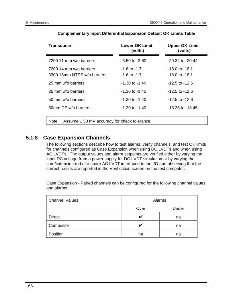
5 Maintenance 3500/45 Operation and Maintenance
166
Complementary Input Differential Expansion Default OK Limits Table
Transducer Lower OK Limit(volts)
Upper OK Limit(volts)
7200 11 mm w/o barriers -3.50 to -3.60 -20.34 to -20.44
7200 14 mm w/o barriers3300 16mm HTPS w/o barriers
-1.6 to -1.7-1.6 to -1.7
-18.0 to -18.1-18.0 to -18.1
25 mm w/o barriers -1.30 to -1.40 -12.5 to -12.6
35 mm w/o barriers -1.30 to -1.40 -12.5 to -12.6
50 mm w/o barriers -1.30 to -1.40 -12.5 to -12.6
50mm DE w/o barriers -1.30 to -1.40 -13.35 to -13.45
Note: Assume ± 50 mV accuracy for check tolerance.
5.1.8 Case Expansion ChannelsThe following sections describe how to test alarms, verify channels, and test OK limitsfor channels configured as Case Expansion when using DC LVDTs and when usingAC LVDTs. The output values and alarm setpoints are verified either by varying theinput DC voltage from a power supply for DC LVDT simulation or by varying thecore/extension rod of a spare AC LVDT interfaced to the I/O and observing that thecorrect results are reported in the Verification screen on the test computer.
Case Expansion - Paired channels can be configured for the following channel valuesand alarms:
Channel Values Alarms
Over Under
Direct na
Composite na
Position na na
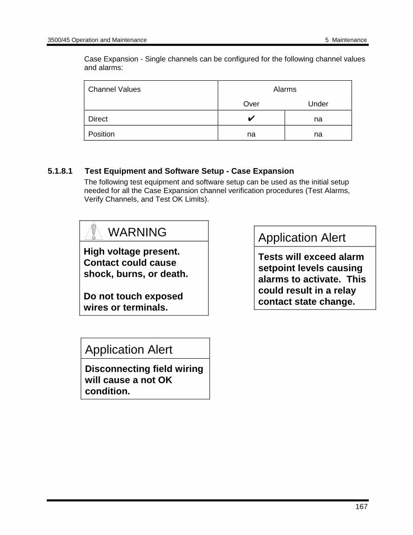
3500/45 Operation and Maintenance 5 Maintenance
167
Case Expansion - Single channels can be configured for the following channel valuesand alarms:
Channel Values Alarms
Over Under
Direct na
Position na na
5.1.8.1 Test Equipment and Software Setup - Case ExpansionThe following test equipment and software setup can be used as the initial setupneeded for all the Case Expansion channel verification procedures (Test Alarms,Verify Channels, and Test OK Limits).
Application Alert
Tests will exceed alarmsetpoint levels causingalarms to activate. Thiscould result in a relaycontact state change.
WARNING
High voltage present.Contact could causeshock, burns, or death.
Do not touch exposedwires or terminals.
Application Alert
Disconnecting field wiringwill cause a not OKcondition.
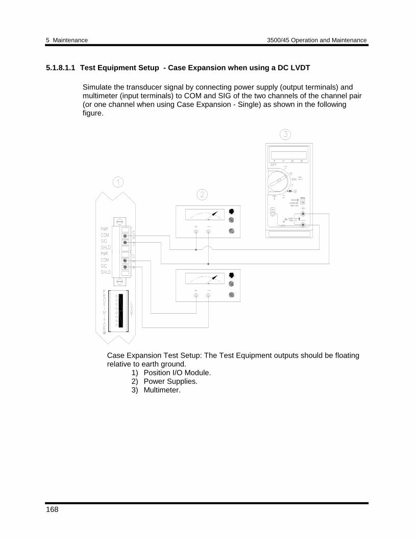
5 Maintenance 3500/45 Operation and Maintenance
168
5.1.8.1.1 Test Equipment Setup - Case Expansion when using a DC LVDT
Simulate the transducer signal by connecting power supply (output terminals) andmultimeter (input terminals) to COM and SIG of the two channels of the channel pair(or one channel when using Case Expansion - Single) as shown in the followingfigure.
Case Expansion Test Setup: The Test Equipment outputs should be floatingrelative to earth ground.
1) Position I/O Module.2) Power Supplies.3) Multimeter.
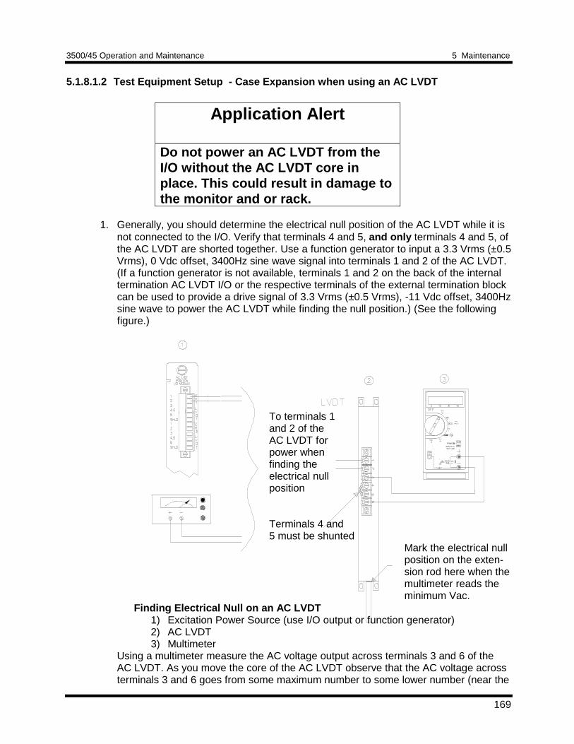
3500/45 Operation and Maintenance 5 Maintenance
169
5.1.8.1.2 Test Equipment Setup - Case Expansion when using an AC LVDT
Application Alert
Do not power an AC LVDT from theI/O without the AC LVDT core inplace. This could result in damage tothe monitor and or rack.
1. Generally, you should determine the electrical null position of the AC LVDT while it isnot connected to the I/O. Verify that terminals 4 and 5, and only terminals 4 and 5, ofthe AC LVDT are shorted together. Use a function generator to input a 3.3 Vrms (±0.5Vrms), 0 Vdc offset, 3400Hz sine wave signal into terminals 1 and 2 of the AC LVDT.(If a function generator is not available, terminals 1 and 2 on the back of the internaltermination AC LVDT I/O or the respective terminals of the external termination blockcan be used to provide a drive signal of 3.3 Vrms (±0.5 Vrms), -11 Vdc offset, 3400Hzsine wave to power the AC LVDT while finding the null position.) (See the followingfigure.)
To terminals 1and 2 of theAC LVDT forpower whenfinding theelectrical nullposition
Terminals 4 and5 must be shunted
Mark the electrical nullposition on the exten-sion rod here when themultimeter reads theminimum Vac.
Finding Electrical Null on an AC LVDT1) Excitation Power Source (use I/O output or function generator)2) AC LVDT3) Multimeter
Using a multimeter measure the AC voltage output across terminals 3 and 6 of theAC LVDT. As you move the core of the AC LVDT observe that the AC voltage acrossterminals 3 and 6 goes from some maximum number to some lower number (near the
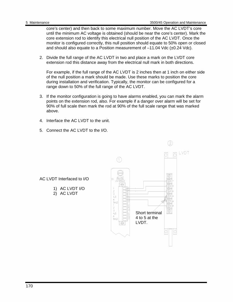
5 Maintenance 3500/45 Operation and Maintenance
170
core’s center) and then back to some maximum number. Move the AC LVDT’s coreuntil the minimum AC voltage is obtained (should be near the core’s center). Mark thecore extension rod to identify this electrical null position of the AC LVDT. Once themonitor is configured correctly, this null position should equate to 50% open or closedand should also equate to a Position measurement of –11.04 Vdc (±0.24 Vdc).
2. Divide the full range of the AC LVDT in two and place a mark on the LVDT coreextension rod this distance away from the electrical null mark in both directions.
For example, if the full range of the AC LVDT is 2 inches then at 1 inch on either sideof the null position a mark should be made. Use these marks to position the coreduring installation and verification. Typically, the monitor can be configured for arange down to 50% of the full range of the AC LVDT.
3. If the monitor configuration is going to have alarms enabled, you can mark the alarmpoints on the extension rod, also. For example if a danger over alarm will be set for90% of full scale then mark the rod at 90% of the full scale range that was markedabove.
4. Interface the AC LVDT to the unit.
5. Connect the AC LVDT to the I/O.
AC LVDT Interfaced to I/O
1) AC LVDT I/O2) AC LVDT
Short terminal4 to 5 at theLVDT.
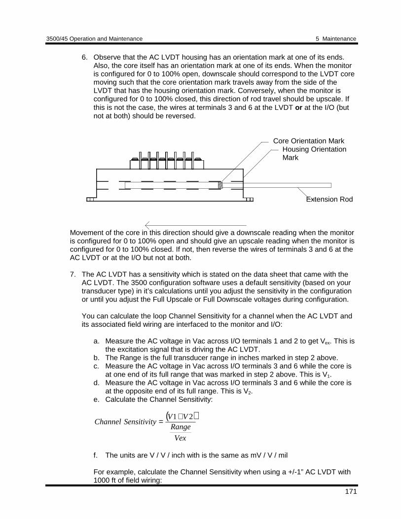
3500/45 Operation and Maintenance 5 Maintenance
171
6. Observe that the AC LVDT housing has an orientation mark at one of its ends.Also, the core itself has an orientation mark at one of its ends. When the monitoris configured for 0 to 100% open, downscale should correspond to the LVDT coremoving such that the core orientation mark travels away from the side of theLVDT that has the housing orientation mark. Conversely, when the monitor isconfigured for 0 to 100% closed, this direction of rod travel should be upscale. Ifthis is not the case, the wires at terminals 3 and 6 at the LVDT or at the I/O (butnot at both) should be reversed.
Core Orientation MarkHousing OrientationMark
Extension Rod
Movement of the core in this direction should give a downscale reading when the monitoris configured for 0 to 100% open and should give an upscale reading when the monitor isconfigured for 0 to 100% closed. If not, then reverse the wires of terminals 3 and 6 at theAC LVDT or at the I/O but not at both.
7. The AC LVDT has a sensitivity which is stated on the data sheet that came with theAC LVDT. The 3500 configuration software uses a default sensitivity (based on yourtransducer type) in it’s calculations until you adjust the sensitivity in the configurationor until you adjust the Full Upscale or Full Downscale voltages during configuration.
You can calculate the loop Channel Sensitivity for a channel when the AC LVDT andits associated field wiring are interfaced to the monitor and I/O:
a. Measure the AC voltage in Vac across I/O terminals 1 and 2 to get Vex. This isthe excitation signal that is driving the AC LVDT.
b. The Range is the full transducer range in inches marked in step 2 above.c. Measure the AC voltage in Vac across I/O terminals 3 and 6 while the core is
at one end of its full range that was marked in step 2 above. This is V1.d. Measure the AC voltage in Vac across I/O terminals 3 and 6 while the core is
at the opposite end of its full range. This is V2.e. Calculate the Channel Sensitivity:
( )
Vex
RangeVV
ySensitivitChannel21+=
f. The units are V / V / inch with is the same as mV / V / mil
For example, calculate the Channel Sensitivity when using a +/-1” AC LVDT with1000 ft of field wiring:
5 Maintenance 3500/45 Operation and Maintenance
172
1) After performing steps 1-5 above, the measured Vex=2.297Vac.2) The measured V1 = 0.974Vac3) The measured V2 = 0.971Vac4) Range=2 inches which is the full transducer range marked in 2 above5) Channel Sensitivity =
(V1 + V2)g/Range/Vex = (0.974 + 0.971) / 2 / 2.297 = 0.423mV/V/mil
Therefore, the Channel Sensitivity for this channel is 0.423 mV/V/mil
8. The Channel Sensitivity can be manually entered during configuration or it will beautomatically calculated and adjusted when you set the full upscale anddownscale voltages of the system.
9. The DC voltage output (Position PPL) at any given AC LVDT rod position isrelated to the Channel Sensitivity by the following:
( ))55.9(04.11 ××±−= dSensitvityChannelVout
where d is the distance moved from the null position and the “±” depends onwhich direction from null the rod has been moved.
5.1.8.1.3 Verification Screen Setup - Case ExpansionRun the Rack Configuration Software on the test computer. Choose Verificationfrom the Utilities menu and choose the proper Slot number and Channel number thenclick on the Verify button.
The following table directs you to the starting page of each maintenance sectionassociated with the Case Expansion Channels.
SectionNumber
Topic PageNumber
5.1.8.2 Test Alarms - Direct 173
5.1.8.2 Test Alarms - Composite 173
5.1.8.3 Verify Channel Values - Direct 175
5.1.8.3 Verify Channel Values - Composite 175
5.1.8.3 Verify Channel Values - Position 175
5.1.8.3 Test OK Limits 175
3500/45 Operation and Maintenance 5 Maintenance
173
5.1.8.2 Test Alarms - Case ExpansionThe general approach for testing alarm setpoints is to simulate the Case Expansionsignals with a power supply or with a spare AC LVDT. The alarm levels are tested byvarying the DC voltage (for DC LVDT simulation) or by moving the AC LVDT core tosimulate the case expansion and observing that the correct results are reported in theVerification screen on the test computer. It is only necessary to test those alarmparameters that are configured and being used. The general test procedure to verifycurrent alarm operation will include simulating transducer input signals and varyingone or more of the signals:
1. to exceed over Alert/Alarm 1 and Danger/Alarm 2 Setpoints2. to produce a non-alarm condition
Direct
1. Disconnect the field wiring from the channel terminals on the I/O Module. 2. Connect test equipment and run software as described in Section 5.1.8.1 (Test
Equipment and Software Setup - Case Expansion). 3. For a DC LVDT channel, adjust the power supply to produce a voltage that is
below the Direct setpoint levels on the Direct bar graph display of the Verificationscreen. For an AC LVDT channel, adjust the core/extension rod to a position thatis below the Direct setpoint levels on the rod.
4. Press the RESET switch on the Rack Interface Module (RIM). Verify that the OKLED is on, the bar graph indicator for Direct is green, and the Current Value Boxhas no alarm indication.
5. For a DC LVDT, adjust the power supply voltages such that the signal justexceeds the Direct Over Alert/Alarm 1 setpoint level. For an AC LVDT channel,adjust the extension rod to a position just beyond the Over Alert/Alarm 1 setpointmark on the rod. Wait for 2 or 3 seconds after the alarm time delay expires andverify that the bar graph indicator for Direct changes color from green to yellow.
6. Press the RESET switch on the Rack Interface Module (RIM). Verify that the bar
graph indicator for Direct remains yellow. 7. For a DC LVDT channel, adjust the power supply such that the signal just
exceeds the Direct Over Danger/Alarm 2 setpoint level. For an AC LVDT, adjustthe extension rod to a position just beyond the Direct Over Danger/Alarm 2setpoint mark on the rod. Wait for 2 or 3 seconds after the alarm time delayexpires and verify that the bar graph indicator for Direct changes color from yellowto red.
8. Press the RESET switch on the Rack Interface Module (RIM). Verify that the bar
graph indicator for Direct remains red. 9. For a DC LVDT, adjust the power supply voltages such that the signal reads
below the Over Alarm setpoint levels. For an AC LVDT, adjust the extension rodto a position below the Over Alarm setpoint marks on the rod. If the nonlatching
5 Maintenance 3500/45 Operation and Maintenance
174
option is configured, observe that the bar graph indicator for Direct changes colorto green and that the Current Value Box contains no indication of alarms. Pressthe RESET switch on the Rack Interface Module (RIM) to reset latching alarms.
10. If you cannot verify any configured alarm, recheck the configured setpoints. If the
monitor still does not alarm properly or fails any other part of this test, go toSection 5.1.11 (If a Channel Fails a Verification Test).
11. Disconnect the test equipment and reconnect the field wiring to the channel
terminals on the I/O Module. Verify that the OK LED comes on and the OK relayenergizes. Press the RESET switch on the Rack Interface Module (RIM) to resetthe OK LED.
12. Repeat steps 1 through 11 for all configured Case Expansion channels.
Composite (Case Expansion - Paired Channels only)
1. Disconnect the field wiring from the terminals of the two Case Expansion channelson the I/O Module.
2. Connect test equipment and run software as described in Section 5.1.8.1 (Test
Equipment and Software Setup - Case Expansion). 3. For DC LVDT channels, adjust the power supplies so that the Composite value is
within the setpoint levels. This can usually be done by setting the power supply to+2.5V for each channel of the channel pair. For AC LVDT channels, adjust theextension rods so that the Composite value is within the setpoint levels. You cancheck each channel of the channel pair by changing the selected channel usingthe Channel dropdown list box in the Verification screen.
4. Press the RESET switch on the Rack Interface Module (RIM). Verify that the OKLED is on, the bar graph indicator for Composite is green, and the CompositeCurrent Value Box has no alarm indication.
5. For DC LVDT channels, adjust the power supply voltages such that the signal just
exceeds the Composite Over Alert/Alarm 1 setpoint level. For AC LVDT channelsadjust the extension rods such that the signal just exceeds the Composite OverAlert/Alarm 1 setpoint level. Wait for 2 or 3 seconds after the alarm time delayexpires and verify that the bar graph indicator for Composite changes color fromgreen to yellow.
6. Press the RESET switch on the Rack Interface Module (RIM). Verify that the bar
graph indicator for Composite remains yellow. 7. For DC LVDT channels, adjust the power supply such that the signal just exceeds
the Composite Over Danger/Alarm 2 setpoint level. For AC LVDT channels, adjustthe extension rods such that the signal just exceeds the Composite OverDanger/Alarm 2 setpoint level. Wait for 2 or 3 seconds after the alarm time delayexpires and verify that the bar graph indicator for Composite changes color fromyellow to red.
3500/45 Operation and Maintenance 5 Maintenance
175
8. Press the RESET switch on the Rack Interface Module (RIM). Verify that the bargraph indicator for Composite remains red.
9. For DC LVDT channels, adjust the power supply voltages such that the signal
reads below the Over Alarm setpoint levels. For AC LVDT channels, adjust theextension rods such that the signal reads below the Over Alarm setpoint levels. Ifthe nonlatching option is configured, observe that the bar graph indicator forComposite changes color to green and that the Current Value Box contains noindication of alarms. Press the RESET switch on the Rack Interface Module (RIM)to reset latching alarms.
10. If you cannot verify any configured alarm, recheck the configured setpoints. If the
monitor still does not alarm properly or fails any other part of this test, go toSection 5.1.11 (If a Channel Fails a Verification Test).
11. Disconnect the test equipment and reconnect the field wiring to the channel
terminals on the I/O Module. Verify that the OK LED comes on and the OK relayenergizes. Press the RESET switch on the Rack Interface Module (RIM) to resetthe OK LED.
12. Repeat steps 1 through 11 for all configured Case Expansion channel pairs.
5.1.8.3 Verify Channel Values - Case ExpansionThe general approach for testing these parameters is to simulate the Case Expansiontransducer signals with a power supply or with a spare AC LVDT on each channel ofthe channel pair. The output values are verified by changing the input DC voltage (forDC LVDT channels) or by moving the spare AC LVDT core/extension rod (for ACLVDT channels) and observing that the correct results are reported in the Verificationscreen on the test computer.
Direct
1. Disconnect the field wiring from the channel terminals on the I/O Module. 2. Connect test equipment and run software as described in Section 5.1.8.1 (Test
Equipment and Software Setup - Case Expansion). 3. For DC LVDT channels, adjust the power supply voltage to match the voltage
displayed in the Upscale Voltage box. For AC LVDT channels, adjust theextension rod to the full upscale endpoint mark on the extension rod. Verify thatthe Direct bar graph display and the Current Value Box is reading ±1% of fullscale. If the recorder is configured, refer to Section 5.1.10 (Verify RecorderOutputs) for steps to verify the recorder output.
4. For DC LVDT channels, adjust the power supply voltage to match the voltage
displayed in the Downscale Voltage box. For AC LVDT channels, adjust theextension rod to the full downscale endpoint mark on the extension rod. Verify thatthe Direct bar graph display and the Current Value Box is reading ±1% of bottomscale. If the recorder is configured, refer to Section 5.1.10 (Verify RecorderOutputs) for steps to verify the recorder output.
5 Maintenance 3500/45 Operation and Maintenance
176
5. If the reading does not meet specifications, check that the input signal is correctand that the monitor is correctly configured. If the monitor still does not meetspecifications or fails any other part of this test, go to Section 5.1.11 (If a ChannelFails a Verification Test).
6. Disconnect the test equipment and reconnect the field wiring to the channel
terminals on the I/O Module. Verify that the OK LED comes on and the OK relayenergizes. Press the RESET switch on the Rack Interface Module (RIM) to resetthe OK LED.
7. Repeat steps 1 through 6 for all configured channels. Composite (Case Expansion - Paired Channels only)The Composite proportional value is the difference (magnitude only) between the twoDirect proportional values of the channel pair.
1. Disconnect the field wiring from the terminals of the two Case Expansion channelson the I/O Module.
2. Connect test equipment and run software as described in Section 5.1.8.1 (Test
Equipment and Software Setup - Case Expansion). 3. For DC LVDT channels, adjust the power supply voltage of channel 4 to match
the voltage displayed in the channel Downscale Voltage box and adjust the powersupply voltage of channel 3 to match the voltage displayed in the channel 3Downscale Voltage box. For AC LVDT channels, adjust the extension rod of thechannel 3 AC LVDT to the full downscale endpoint mark on the extension rod andadjust the extension rod of the channel 4 AC LVDT to the full downscale endpointmark on the extension rod. Verify that the Composite bar graph display and theCurrent Value Box is reading ±1% of bottom scale. If the recorder is configured,refer to Section 5.1.10 (Verify Recorder Outputs) for steps to verify the recorderoutput.
4. Adjust the power supply voltage of channel 4 to match the voltage displayed in thechannel 4 Downscale Voltage box. Calculate the channel 3 voltage which gives afull scale Composite reading using the formula below:
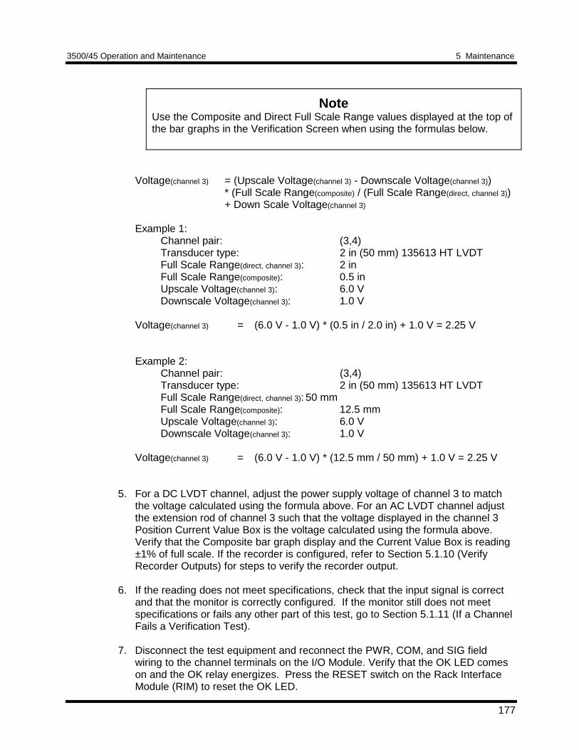
3500/45 Operation and Maintenance 5 Maintenance
177
NoteUse the Composite and Direct Full Scale Range values displayed at the top ofthe bar graphs in the Verification Screen when using the formulas below.
Voltage(channel 3) = (Upscale Voltage(channel 3) - Downscale Voltage(channel 3))* (Full Scale Range(composite) / (Full Scale Range(direct, channel 3))+ Down Scale Voltage(channel 3)
Example 1:Channel pair: (3,4)Transducer type: 2 in (50 mm) 135613 HT LVDTFull Scale Range(direct, channel 3): 2 inFull Scale Range(composite): 0.5 inUpscale Voltage(channel 3): 6.0 VDownscale Voltage(channel 3): 1.0 V
Voltage(channel 3) = (6.0 V - 1.0 V) * (0.5 in / 2.0 in) + 1.0 V = 2.25 V
Example 2:Channel pair: (3,4)Transducer type: 2 in (50 mm) 135613 HT LVDTFull Scale Range(direct, channel 3): 50 mmFull Scale Range(composite): 12.5 mmUpscale Voltage(channel 3): 6.0 VDownscale Voltage(channel 3): 1.0 V
Voltage(channel 3) = (6.0 V - 1.0 V) * (12.5 mm / 50 mm) + 1.0 V = 2.25 V
5. For a DC LVDT channel, adjust the power supply voltage of channel 3 to matchthe voltage calculated using the formula above. For an AC LVDT channel adjustthe extension rod of channel 3 such that the voltage displayed in the channel 3Position Current Value Box is the voltage calculated using the formula above.Verify that the Composite bar graph display and the Current Value Box is reading±1% of full scale. If the recorder is configured, refer to Section 5.1.10 (VerifyRecorder Outputs) for steps to verify the recorder output.
6. If the reading does not meet specifications, check that the input signal is correctand that the monitor is correctly configured. If the monitor still does not meetspecifications or fails any other part of this test, go to Section 5.1.11 (If a ChannelFails a Verification Test).
7. Disconnect the test equipment and reconnect the PWR, COM, and SIG field
wiring to the channel terminals on the I/O Module. Verify that the OK LED comeson and the OK relay energizes. Press the RESET switch on the Rack InterfaceModule (RIM) to reset the OK LED.
5 Maintenance 3500/45 Operation and Maintenance
178
8. Repeat steps 1 through 7 for all configured channels.
Position
1. Disconnect the field wiring from the channel terminals on the I/O Module. 2. Connect test equipment and run software as described in Section 5.1.8.1 (Test
Equipment and Software Setup - Case Expansion). 3. For DC LVDT channels, adjust the power supply voltage to produce a voltage
equal to -5.00 Vdc. Verify that the Position bar graph display and the CurrentValue box are reading within ±1% of -5.00 Vdc. For AC LVDT channels, adjust thespare AC LVDT extension rod to its downscale mark. Verify that the Position bargraph Display and the Current Value box are reading ±1% of the voltage shown inthe Downscale Voltage box.
4. Adjust the power supply voltage to produce a voltage equal to +5.00 Vdc. Verify
that the Position bar graph display and the Current Value Box is reading within±1% of +5.00 Vdc. For AC LVDT channels, adjust the spare AC LVDT extensionrod to its upscale mark. Verify that the Position bar graph Display and the CurrentValue box are reading ±1% of the voltage shown in the Upscale Voltage box.
5. If the reading does not meet specifications, check that the input signal is correct
and that the monitor is correctly configured. If the monitor still does not meetspecifications or fails any other part of this test, go to Section 5.1.11 (If a ChannelFails a Verification Test).
6. Disconnect the test equipment and reconnect the PWR, COM, and SIG field
wiring to the channel terminals on the I/O Module. Verify that the OK LED comeson and the OK relay energizes. Press the RESET switch on the Rack InterfaceModule (RIM) to reset the OK LED.
7. Repeat steps 1 through 6 for all configured channels.
5.1.8.4 Test OK Limits - Case ExpansionThe general approach for testing OK limits is to simulate the Case Expansion signalson both channels with power supplies or with spare AC LVDTs. The OK Limits aretested by varying the DC voltage of the power supplies (for DC LVDT simulation) orby moving the AC LVDT core to vary the voltage above the Upper OK Limit and belowthe Lower OK Limit. This will cause a channel not OK condition and the OK Relay tochange state (de-energize). The Upper and Lower OK limits are displayed in theVerification screen on the test computer. The table on page 181 lists the default OKlimits for common transducers.
1. Disconnect the field wiring from the channel terminals on the I/O Module. 2. Connect test equipment and run software as described in Section 5.1.8.1 (Test
Equipment and Software Setup - Case Expansion). Connect to both channels.
3500/45 Operation and Maintenance 5 Maintenance
179
3. Bypass all other configured channels. 4. For DC LVDT channels, adjust the power supply voltage to +2.00 Vdc. For AC
LVDT channels, adjust the spare AC LVDTs’ core/extension rod to a positionbetween the full scale endpoint marks. Verify that the Position bar graph display ofthe Verification screen reads within the OK Limits for the AC LVDT.
5. Press the RESET switch on the Rack Interface Module (RIM). Verify that the
monitor OK LED is on and that the Channel OK State line in the Channel Statusbox of the Verification screen reads OK.
NoteIf the Danger Bypass has been activated, then the BYPASS LED will be on. Allother channels in the rack must be OK or bypassed for the OK relay to be energized.
6. Verify that the OK relay on the Rack Interface I/O Module indicates OK(energized). See 3500/20 Rack Interface Module Operation and MaintenanceManual, part number 129768-01.
7. For DC LVDT channels, increase the power supply voltage (more positive) until
the OK LED just goes off (upper limit). For AC LVDT channels, adjust theextension rod so that the voltage goes more negative until the OK LED just goesoff. Verify that the Channel OK State line in the Channel Status box reads not OKand that the OK Relay indicates not OK. For the DC LVDT channels, verify thatthe Upper OK limit voltage displayed on the Verification screen is equal to or lesspositive than the input voltage. For the AC LVDT channels, verify that the UpperOK Limit voltage displayed on the Verification screen is equal to or more positivethan the voltage read in the Current Value box in the Verification screen.
8. For DC LVDT channels, decrease the power supply voltage (less positive) to+2.00 Vdc. For AC LVDT channels, adjust the spare AC LVDTs’ core/extensionrod to a position between the full scale endpoint marks.
9. Press the RESET switch on the Rack Interface Module (RIM). Verify that the OKLED comes back on, the OK relay energizes, and the Channel OK State line inthe Channel Status box reads OK.
10. For DC LVDT channels, gradually decrease the power supply voltage (less
positive) until the OK LED just goes off (lower limit). For AC LVDT channels,adjust the extension rod so that the voltage goes more positive until the OK LEDjust goes off. Verify that the Channel OK State line in the Channel Status boxreads not OK and that the OK Relay indicates not OK. For DC LVDT channels,verify that the Lower OK limit voltage displayed on the Verification screen is equalto or more positive than the input voltage. For AC LVDT channels, verify that theLower OK limit voltage displayed on the Verification screen is equal to or lesspositive than the voltage read in the Current Value box in the Verification screen.
11. For DC LVDT channels, increase the power supply voltage (more positive) to
+2.00 Vdc. For AC LVDT channels, adjust the spare AC LVDTs’ core/extensionrod to a position between the full scale endpoint marks.
5 Maintenance 3500/45 Operation and Maintenance
180
12. Press the RESET switch on the Rack Interface Module (RIM). Verify that the OK
LED comes back on, the OK relay energizes, and the Channel OK State line inthe Channel Status box reads OK.
13. If you cannot verify any configured OK limit, go to Section 5.1.11 (If a Channel
Fails a Verification Test). 14. Disconnect the test equipment and reconnect the field wiring to the channel
terminals on the I/O module. Press the RESET switch on the Rack InterfaceModule (RIM) and verify that the OK LED comes on and the OK relay energizes.
15. Repeat steps 1 through 14 for all configured channels. 16. Return the bypass switch for all configured channels to their original setting.
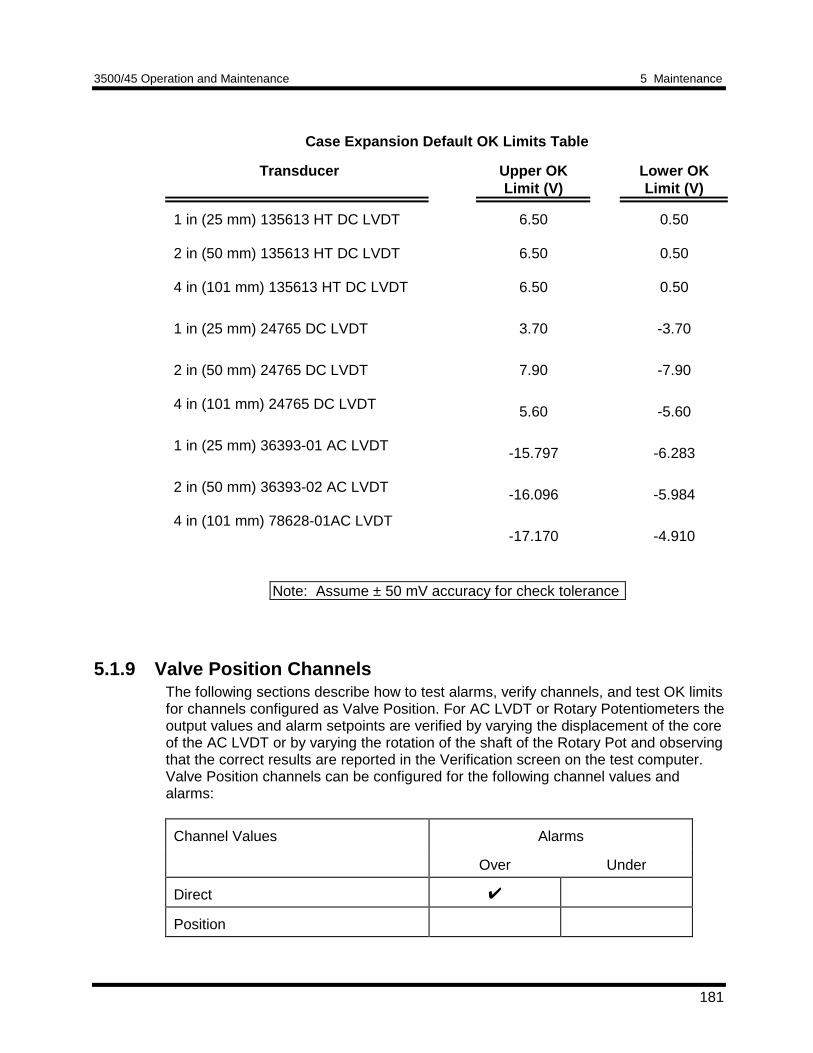
3500/45 Operation and Maintenance 5 Maintenance
181
Case Expansion Default OK Limits Table
Transducer Upper OKLimit (V)
Lower OKLimit (V)
1 in (25 mm) 135613 HT DC LVDT
2 in (50 mm) 135613 HT DC LVDT
4 in (101 mm) 135613 HT DC LVDT
1 in (25 mm) 24765 DC LVDT
2 in (50 mm) 24765 DC LVDT
4 in (101 mm) 24765 DC LVDT
1 in (25 mm) 36393-01 AC LVDT
2 in (50 mm) 36393-02 AC LVDT
4 in (101 mm) 78628-01AC LVDT
6.50
6.50
6.50
3.70
7.90
5.60
-15.797
-16.096
-17.170
0.50
0.50
0.50
-3.70
-7.90
-5.60
-6.283
-5.984
-4.910
5.1.9 Valve Position ChannelsThe following sections describe how to test alarms, verify channels, and test OK limitsfor channels configured as Valve Position. For AC LVDT or Rotary Potentiometers theoutput values and alarm setpoints are verified by varying the displacement of the coreof the AC LVDT or by varying the rotation of the shaft of the Rotary Pot and observingthat the correct results are reported in the Verification screen on the test computer.Valve Position channels can be configured for the following channel values andalarms:
Channel Values Alarms
Over Under
Direct
Position
Note: Assume ± 50 mV accuracy for check tolerance
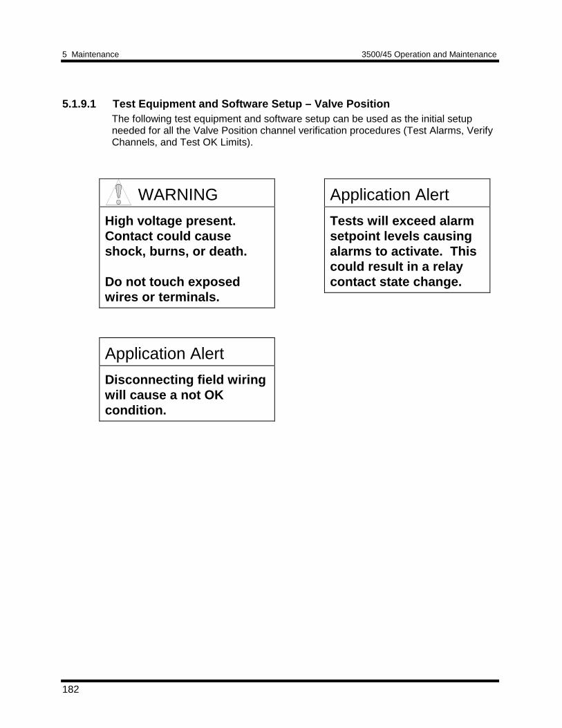
5 Maintenance 3500/45 Operation and Maintenance
182
5.1.9.1 Test Equipment and Software Setup – Valve PositionThe following test equipment and software setup can be used as the initial setupneeded for all the Valve Position channel verification procedures (Test Alarms, VerifyChannels, and Test OK Limits).
Application Alert
Tests will exceed alarmsetpoint levels causingalarms to activate. Thiscould result in a relaycontact state change.
WARNING
High voltage present.Contact could causeshock, burns, or death.
Do not touch exposedwires or terminals.
Application Alert
Disconnecting field wiringwill cause a not OKcondition.
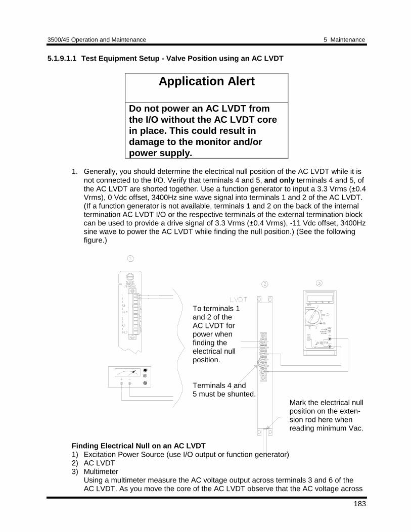
3500/45 Operation and Maintenance 5 Maintenance
183
5.1.9.1.1 Test Equipment Setup - Valve Position using an AC LVDT
Application Alert
Do not power an AC LVDT fromthe I/O without the AC LVDT corein place. This could result indamage to the monitor and/orpower supply.
1. Generally, you should determine the electrical null position of the AC LVDT while it isnot connected to the I/O. Verify that terminals 4 and 5, and only terminals 4 and 5, ofthe AC LVDT are shorted together. Use a function generator to input a 3.3 Vrms (±0.4Vrms), 0 Vdc offset, 3400Hz sine wave signal into terminals 1 and 2 of the AC LVDT.(If a function generator is not available, terminals 1 and 2 on the back of the internaltermination AC LVDT I/O or the respective terminals of the external termination blockcan be used to provide a drive signal of 3.3 Vrms (±0.4 Vrms), -11 Vdc offset, 3400Hzsine wave to power the AC LVDT while finding the null position.) (See the followingfigure.)
To terminals 1and 2 of theAC LVDT forpower whenfinding theelectrical nullposition.
Terminals 4 and5 must be shunted.
Mark the electrical nullposition on the exten-sion rod here whenreading minimum Vac.
Finding Electrical Null on an AC LVDT1) Excitation Power Source (use I/O output or function generator)2) AC LVDT3) Multimeter
Using a multimeter measure the AC voltage output across terminals 3 and 6 of theAC LVDT. As you move the core of the AC LVDT observe that the AC voltage across
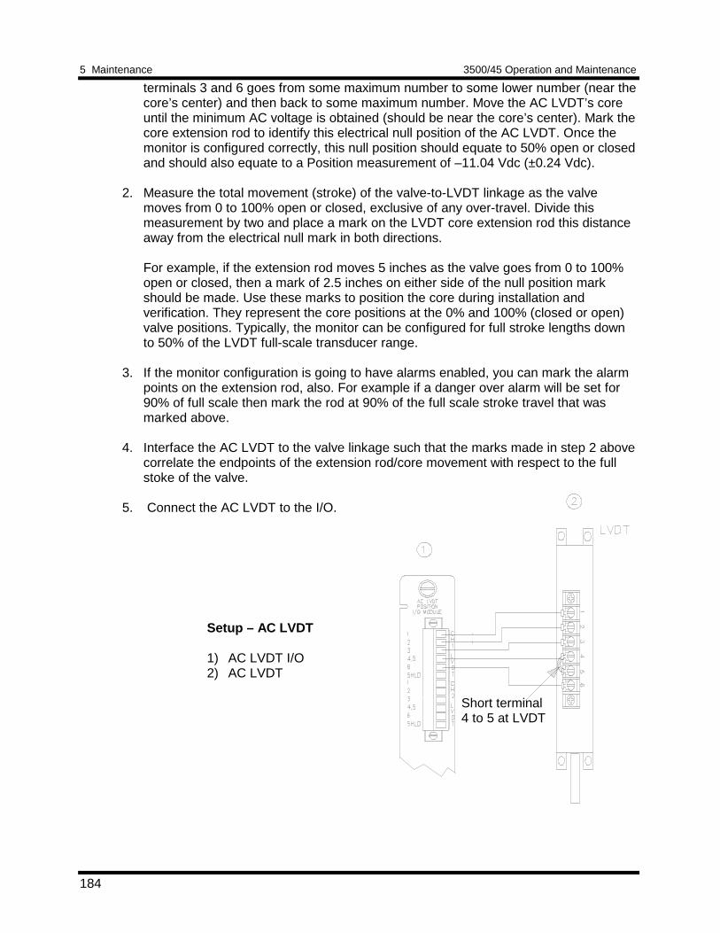
5 Maintenance 3500/45 Operation and Maintenance
184
terminals 3 and 6 goes from some maximum number to some lower number (near thecore’s center) and then back to some maximum number. Move the AC LVDT’s coreuntil the minimum AC voltage is obtained (should be near the core’s center). Mark thecore extension rod to identify this electrical null position of the AC LVDT. Once themonitor is configured correctly, this null position should equate to 50% open or closedand should also equate to a Position measurement of –11.04 Vdc (±0.24 Vdc).
2. Measure the total movement (stroke) of the valve-to-LVDT linkage as the valvemoves from 0 to 100% open or closed, exclusive of any over-travel. Divide thismeasurement by two and place a mark on the LVDT core extension rod this distanceaway from the electrical null mark in both directions.
For example, if the extension rod moves 5 inches as the valve goes from 0 to 100%open or closed, then a mark of 2.5 inches on either side of the null position markshould be made. Use these marks to position the core during installation andverification. They represent the core positions at the 0% and 100% (closed or open)valve positions. Typically, the monitor can be configured for full stroke lengths downto 50% of the LVDT full-scale transducer range.
3. If the monitor configuration is going to have alarms enabled, you can mark the alarmpoints on the extension rod, also. For example if a danger over alarm will be set for90% of full scale then mark the rod at 90% of the full scale stroke travel that wasmarked above.
4. Interface the AC LVDT to the valve linkage such that the marks made in step 2 abovecorrelate the endpoints of the extension rod/core movement with respect to the fullstoke of the valve.
5. Connect the AC LVDT to the I/O.
Setup – AC LVDT
1) AC LVDT I/O2) AC LVDT
Short terminal4 to 5 at LVDT
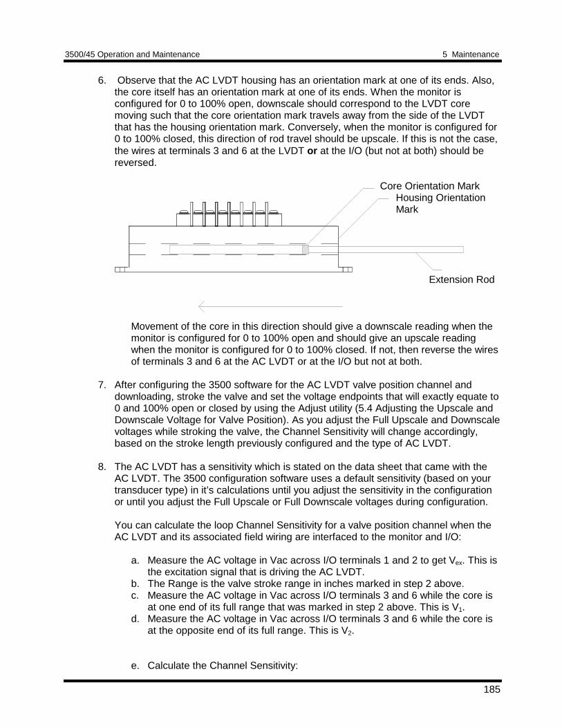
3500/45 Operation and Maintenance 5 Maintenance
185
6. Observe that the AC LVDT housing has an orientation mark at one of its ends. Also,the core itself has an orientation mark at one of its ends. When the monitor isconfigured for 0 to 100% open, downscale should correspond to the LVDT coremoving such that the core orientation mark travels away from the side of the LVDTthat has the housing orientation mark. Conversely, when the monitor is configured for0 to 100% closed, this direction of rod travel should be upscale. If this is not the case,the wires at terminals 3 and 6 at the LVDT or at the I/O (but not at both) should bereversed.
Core Orientation MarkHousing OrientationMark
Extension Rod
Movement of the core in this direction should give a downscale reading when themonitor is configured for 0 to 100% open and should give an upscale readingwhen the monitor is configured for 0 to 100% closed. If not, then reverse the wiresof terminals 3 and 6 at the AC LVDT or at the I/O but not at both.
7. After configuring the 3500 software for the AC LVDT valve position channel anddownloading, stroke the valve and set the voltage endpoints that will exactly equate to0 and 100% open or closed by using the Adjust utility (5.4 Adjusting the Upscale andDownscale Voltage for Valve Position). As you adjust the Full Upscale and Downscalevoltages while stroking the valve, the Channel Sensitivity will change accordingly,based on the stroke length previously configured and the type of AC LVDT.
8. The AC LVDT has a sensitivity which is stated on the data sheet that came with theAC LVDT. The 3500 configuration software uses a default sensitivity (based on yourtransducer type) in it’s calculations until you adjust the sensitivity in the configurationor until you adjust the Full Upscale or Full Downscale voltages during configuration.
You can calculate the loop Channel Sensitivity for a valve position channel when theAC LVDT and its associated field wiring are interfaced to the monitor and I/O:
a. Measure the AC voltage in Vac across I/O terminals 1 and 2 to get Vex. This isthe excitation signal that is driving the AC LVDT.
b. The Range is the valve stroke range in inches marked in step 2 above.c. Measure the AC voltage in Vac across I/O terminals 3 and 6 while the core is
at one end of its full range that was marked in step 2 above. This is V1.d. Measure the AC voltage in Vac across I/O terminals 3 and 6 while the core is
at the opposite end of its full range. This is V2.
e. Calculate the Channel Sensitivity:
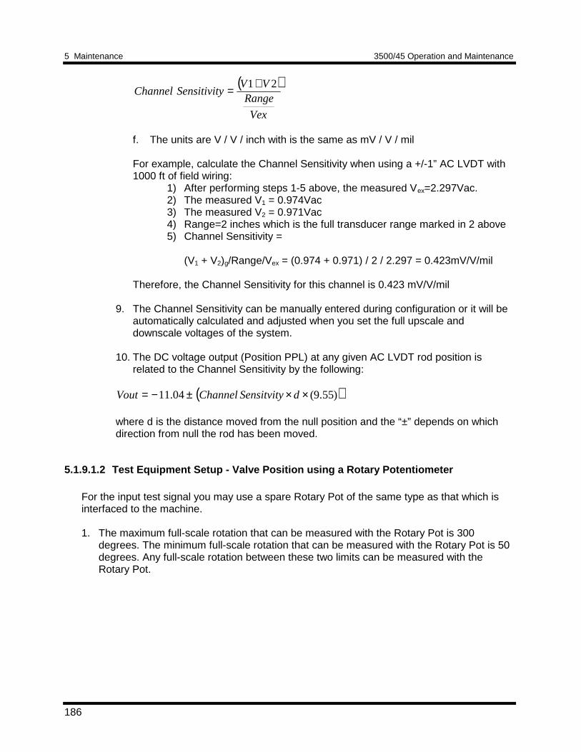
5 Maintenance 3500/45 Operation and Maintenance
186
( )
Vex
RangeVV
ySensitivitChannel21+=
f. The units are V / V / inch with is the same as mV / V / mil
For example, calculate the Channel Sensitivity when using a +/-1” AC LVDT with1000 ft of field wiring:
1) After performing steps 1-5 above, the measured Vex=2.297Vac.2) The measured V1 = 0.974Vac3) The measured V2 = 0.971Vac4) Range=2 inches which is the full transducer range marked in 2 above5) Channel Sensitivity =
(V1 + V2)g/Range/Vex = (0.974 + 0.971) / 2 / 2.297 = 0.423mV/V/mil
Therefore, the Channel Sensitivity for this channel is 0.423 mV/V/mil
9. The Channel Sensitivity can be manually entered during configuration or it will beautomatically calculated and adjusted when you set the full upscale anddownscale voltages of the system.
10. The DC voltage output (Position PPL) at any given AC LVDT rod position isrelated to the Channel Sensitivity by the following:
( ))55.9(04.11 ××±−= dSensitvityChannelVout
where d is the distance moved from the null position and the “±” depends on whichdirection from null the rod has been moved.
5.1.9.1.2 Test Equipment Setup - Valve Position using a Rotary Potentiometer
For the input test signal you may use a spare Rotary Pot of the same type as that which isinterfaced to the machine.
1. The maximum full-scale rotation that can be measured with the Rotary Pot is 300degrees. The minimum full-scale rotation that can be measured with the Rotary Pot is 50degrees. Any full-scale rotation between these two limits can be measured with theRotary Pot.
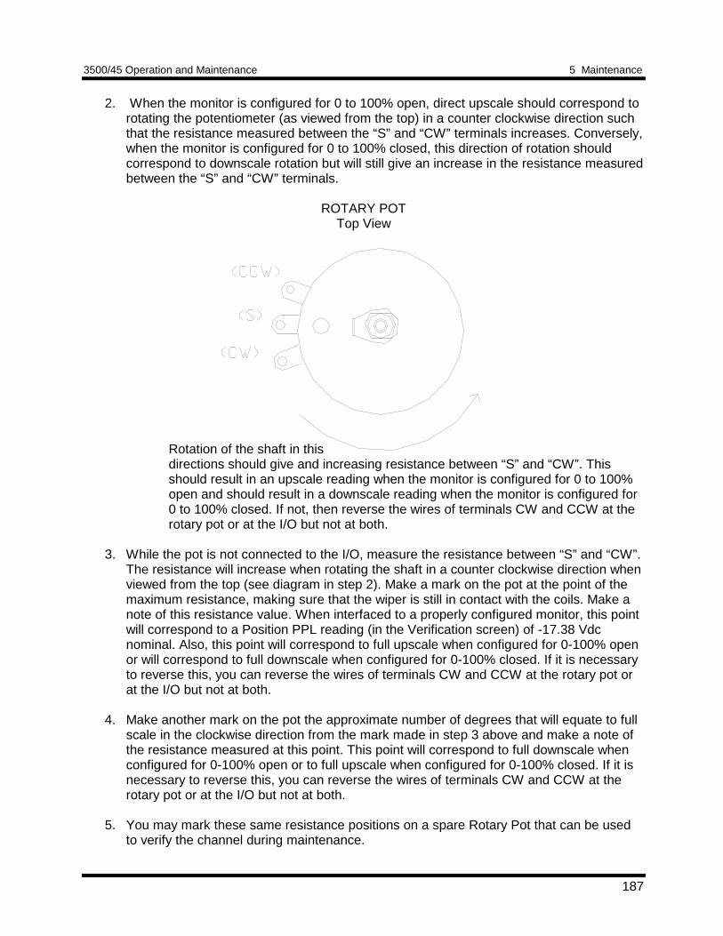
3500/45 Operation and Maintenance 5 Maintenance
187
2. When the monitor is configured for 0 to 100% open, direct upscale should correspond torotating the potentiometer (as viewed from the top) in a counter clockwise direction suchthat the resistance measured between the “S” and “CW” terminals increases. Conversely,when the monitor is configured for 0 to 100% closed, this direction of rotation shouldcorrespond to downscale rotation but will still give an increase in the resistance measuredbetween the “S” and “CW” terminals.
ROTARY POTTop View
Rotation of the shaft in thisdirections should give and increasing resistance between “S” and “CW”. Thisshould result in an upscale reading when the monitor is configured for 0 to 100%open and should result in a downscale reading when the monitor is configured for0 to 100% closed. If not, then reverse the wires of terminals CW and CCW at therotary pot or at the I/O but not at both.
3. While the pot is not connected to the I/O, measure the resistance between “S” and “CW”.The resistance will increase when rotating the shaft in a counter clockwise direction whenviewed from the top (see diagram in step 2). Make a mark on the pot at the point of themaximum resistance, making sure that the wiper is still in contact with the coils. Make anote of this resistance value. When interfaced to a properly configured monitor, this pointwill correspond to a Position PPL reading (in the Verification screen) of -17.38 Vdcnominal. Also, this point will correspond to full upscale when configured for 0-100% openor will correspond to full downscale when configured for 0-100% closed. If it is necessaryto reverse this, you can reverse the wires of terminals CW and CCW at the rotary pot orat the I/O but not at both.
4. Make another mark on the pot the approximate number of degrees that will equate to fullscale in the clockwise direction from the mark made in step 3 above and make a note ofthe resistance measured at this point. This point will correspond to full downscale whenconfigured for 0-100% open or to full upscale when configured for 0-100% closed. If it isnecessary to reverse this, you can reverse the wires of terminals CW and CCW at therotary pot or at the I/O but not at both.
5. You may mark these same resistance positions on a spare Rotary Pot that can be usedto verify the channel during maintenance.
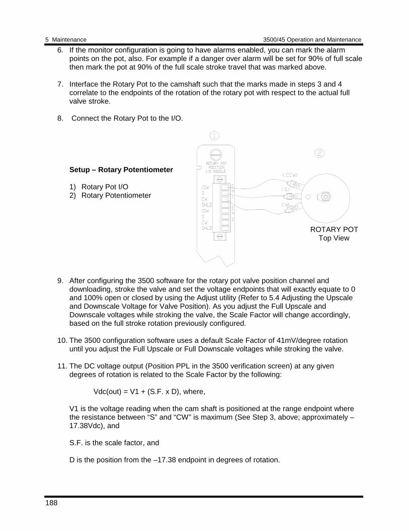
5 Maintenance 3500/45 Operation and Maintenance
188
6. If the monitor configuration is going to have alarms enabled, you can mark the alarmpoints on the pot, also. For example if a danger over alarm will be set for 90% of full scalethen mark the pot at 90% of the full scale stroke travel that was marked above.
7. Interface the Rotary Pot to the camshaft such that the marks made in steps 3 and 4correlate to the endpoints of the rotation of the rotary pot with respect to the actual fullvalve stroke.
8. Connect the Rotary Pot to the I/O.
Setup – Rotary Potentiometer
1) Rotary Pot I/O2) Rotary Potentiometer
ROTARY POT Top View
9. After configuring the 3500 software for the rotary pot valve position channel anddownloading, stroke the valve and set the voltage endpoints that will exactly equate to 0and 100% open or closed by using the Adjust utility (Refer to 5.4 Adjusting the Upscaleand Downscale Voltage for Valve Position). As you adjust the Full Upscale andDownscale voltages while stroking the valve, the Scale Factor will change accordingly,based on the full stroke rotation previously configured.
10. The 3500 configuration software uses a default Scale Factor of 41mV/degree rotationuntil you adjust the Full Upscale or Full Downscale voltages while stroking the valve.
11. The DC voltage output (Position PPL in the 3500 verification screen) at any givendegrees of rotation is related to the Scale Factor by the following:
Vdc(out) = V1 + (S.F. x D), where,
V1 is the voltage reading when the cam shaft is positioned at the range endpoint wherethe resistance between “S” and “CW” is maximum (See Step 3, above; approximately –17.38Vdc), and
S.F. is the scale factor, and
D is the position from the –17.38 endpoint in degrees of rotation.
3500/45 Operation and Maintenance 5 Maintenance
189
5.1.9.1.3 Verification Screen Setup - Valve PositionRun the Rack Configuration Software on the test computer. Choose Verification fromthe Utilities menu and choose the proper Slot number and Channel number then clickon the Verify button.
The following table directs you to the starting page of each maintenance sectionassociated with the Case Expansion Channels.
SectionNumber
Topic PageNumber
5.1.9.2 Test Alarms 189
5.1.9.3 Verify Channel Values 190
5.1.9.4 Test OK Limits 192
5.1.9.2 Test Alarms – Valve PositionThe general approach for testing alarm setpoints is to simulate the Valve Positionsignals with a spare AC LVDT, or with a spare rotary potentiometer. The alarm levelsare tested by moving the AC LVDT core or by rotating the Rotary Pot shaft tosimulate the valve movement and observing that the correct results are reported inthe Verification screen on the test computer. It is only necessary to test those alarmparameters that are configured and being used. The input test signals will be varied:
1. to exceed over Alert/Alarm 1 and Danger/Alarm 2 Setpoints,2. to produce a non-alarm condition.
Direct
1. Disconnect the field wiring from the channel terminals on the I/O Module. 2. Connect test equipment and run software as described in Section5.1.9.1 (Test
Equipment and Software Setup – Valve Position).
3. For an AC LVDT channel adjust the core/extension rod to a position that is belowthe Direct setpoint marks on the rod. For a Rotary Pot channel adjust the shaft toa position that is below the Direct setpoint marks on the pot.
4. Press the RESET switch on the Rack Interface Module (RIM). Verify that the OKLED is on, the bar graph indicator for Direct is green, and the Current Value Boxhas no alarm indication.
5. For an AC LVDT channel adjust the extension rod to a position just beyond theDirect Alert/Alarm 1 mark on the extension rod. For a Rotary Pot channel adjustthe shaft to a position just beyond the Direct Alert/Alarm 1 mark on the Pot. Waitfor 2 or 3 seconds after the alarm time delay expires and verify that the bar graphindicator for Direct changes color from green to yellow.
5 Maintenance 3500/45 Operation and Maintenance
190
6. Press the RESET switch on the Rack Interface Module (RIM). Verify that the bargraph indicator for Direct remains yellow.
7. For an AC LVDT channel adjust the extension rod to a position just beyond theDirect Danger/Alarm 2 mark on the extension rod. For a Rotary Pot channel adjustthe shaft to a position just beyond the Direct Danger/Alarm 2 mark on the Pot.Wait for 2 or 3 seconds after the alarm time delay expires and verify that the bargraph indicator for Direct changes color from yellow to red.
8. Press the RESET switch on the Rack Interface Module (RIM). Verify that the bargraph indicator for Direct remains red.
9. For an AC LVDT channel adjust the extension rod to a position just below theDirect Alarm marks on the extension rod. For a Rotary Pot channel adjust theshaft to a position just below the Direct Alarm marks on the Pot. If the non-latching option is configured, observe that the bar graph indicator for Directchanges color to green and that the Current Value Box contains no indication ofalarms. Press the RESET switch on the Rack Interface Module (RIM) to resetlatching alarms.
10. If you cannot verify any configured alarm, recheck the configured setpoints. If themonitor still does not alarm properly or fails any other part of this test, go toSection 5.1.11 (If a Channel Fails a Verification Test).
11. Disconnect the test equipment and reconnect the field wiring to the channelterminals on the I/O Module. Verify that the OK LED comes on and the OK relayenergizes. Press the RESET switch on the Rack Interface Module (RIM) to resetthe OK LED.
12. Repeat steps 1 through 16 for all configured Valve Position channels.
5.1.9.3 Verify Channel Values – Valve PositionThe general approach for testing these parameters is to simulate the Valve Positionsignals with a spare AC LVDT, or with a spare Rotary Potentiometer. The outputvalues are verified by moving the spare AC LVDT core or rotating the spare RotaryPot shaft to simulate the valve movement and observing that the correct results arereported in the Verification screen on the test computer.
Direct
1. Disconnect the field wiring from the channel terminals on the I/O Module. 2. Connect test equipment and run software as described in Section 5.1.9.1(Test
Equipment and Software Setup – Valve Position).
3. For an AC LVDT channel adjust the extension rod to the full upscale endpointmark on the extension rod. For a Rotary Pot channel adjust the shaft to the fullupscale endpoint mark on the Pot. Verify that the Direct bar graph display and theCurrent Value Box is reading ± 1% of full scale for AC LVDT channels or ± 2% of
3500/45 Operation and Maintenance 5 Maintenance
191
full scale for Rotary Potentiometer channels. If the recorder is configured, refer toSection 5.1.10 (Verify Recorder Outputs) for steps to verify the recorder output.
4. For an AC LVDT channel adjust the extension rod to the full downscale endpointmark on the extension rod. For a Rotary Pot channel adjust the shaft to the fulldownscale endpoint mark on the pot. Verify that the Direct bar graph display andthe Current Value Box is reading ± 1% of full scale dor AC LVDT channels orreading ± 2% of full scale for Rotary Pot channels. If the recorder is configured,refer to Section 5.1.10 (Verify Recorder Outputs) for steps to verify the recorderoutput.
5. If the reading does not meet specifications, check that the input signal is correct
and that the monitor is correctly configured. If the monitor still does not meetspecifications or fails any other part of this test, go to Section 5.1.11 (If a ChannelFails a Verification Test).
6. Disconnect the test equipment and reconnect the field wiring to the channel
terminals on the I/O Module. Verify that the OK LED comes on and the OK relayenergizes. Press the RESET switch on the Rack Interface Module (RIM) to resetthe OK LED.
7. Repeat steps 1 through 6 for all configured channels.
Position
1. Disconnect the field wiring from the channel terminals on the I/O Module. 2. Connect test equipment and run software as described in Section 5.1.9.1 (Test
Equipment and Software Setup – Valve Position).
3. For an AC LVDT channel adjust the extension rod to the full downscale endpointmark on the extension rod. For a Rotary Pot channel adjust the shaft to the fulldownscale endpoint mark on the pot. Verify that the Position bar graph displayand the Current Value Box is reading the configured full downscale voltage ± 1%full scale for AC LVDT channels or ± 2% of full scale for Rotary Pot channels.
4. For an AC LVDT channel adjust the extension rod to the full upscale endpointmark on the extension rod. For a Rotary Pot channel adjust the shaft to the fullupscale endpoint mark on the pot. Verify that the Position bar graph display andthe Current Value Box is reading the configured full upscale voltage ± 1% of fullscale for AC LVDT channels or ± 2% of full scale for Rotary Pot channels.
5. If the reading does not meet specifications, check that the input signal is correctand that the monitor is correctly configured. If the monitor still does not meetspecifications or fails any other part of this test, go to Section 5.1.11 (If a ChannelFails a Verification Test).
6. Disconnect the test equipment and reconnect the field wiring to the channel
terminals on the I/O Module. Verify that the OK LED comes on and the OK relayenergizes. Press the RESET switch on the Rack Interface Module (RIM) to resetthe OK LED.
5 Maintenance 3500/45 Operation and Maintenance
192
7. Repeat steps 1 through 6 for all configured channels.
5.1.9.4 Test OK Limits – Valve PositionThe general approach for testing OK Limits is to open or short the field wiring of theAC LVDT or the Rotary Potentiometer. (In addition, the 1in, 2in, and 4in AC LVDTscan be OK limit tested by moving the extension rod/core of the transducer to causethe voltage to exceed the OK limits.) This will cause a channel not OK condition andthe OK Relay to change state (de-energize). The Upper and Lower OK limits aredisplayed in the Verification screen on the test computer. The table at the end of thissection lists the default OK limits for common transducers.
1. Run software as described in Section 5.1.9.1 (Test Equipment and SoftwareSetup – Valve Position).
2. Bypass all other configured channels.
3. For an AC LVDT channel adjust the core to a position between the full scaleendpoint marks. Verify that the Position bar graph display in the Verificationscreen reads within the OK Limits for the AC LVDT. For a Rotary Pot channeladjust the shaft to a position between the full scale endpoint marks on the pot.Verify that the Position bar graph display in the Verification screen reads withinthe OK Limits for the Rotary Pot.
4. Press the RESET switch on the Rack Interface Module (RIM). Verify that the
monitor OK LED is on and that the Channel OK State line in the Channel Statusbox of the Verification screen reads OK.
NoteIf the Danger Bypass has been activated, then the BYPASS LED will be on. All otherchannels in the rack must be OK or bypassed for the OK relay to be energized.
5. Verify that the OK relay on the Rack Interface I/O Module indicates OK(energized). See 3500/20 Rack Interface Module Operation and MaintenanceManual, part number 129768-01.
6. For a Rotary Pot channel open CW or CCW of the field wiring and verify that theOK LED goes off. (You may, for a 1in, 2in, or 4in AC LVDT channel, disconnectthe extension rod from the valve linkage and adjust the extension rod to increasethe voltage (less negative) until the OK LED just goes off.) Verify that the ChannelOK State line in the Channel Status box reads not OK and that the OK Relayindicates not OK. Verify that the Lower OK limit voltage displayed on theVerification screen is equal to or just below (more negative than) the input voltage.
7. Reconnect the field wiring and/or adjust the extension rod position of the AC
LVDT or reconnect the field wiring to the pot and adjust the pot shaft position tothose positions set in step 3 above.
8. Press the RESET switch on the Rack Interface Module (RIM). Verify that the OK
3500/45 Operation and Maintenance 5 Maintenance
193
LED comes back on, the OK relay energizes, and the Channel OK State line inthe Channel Status box reads OK.
9. For an AC LVDT channel open terminal 1 and 2 at the AC LVDT or at the I/O and
verify that the OK LED goes off. (You may, for a 1in, 2in, and 4in AC LVDTchannel adjust the extension rod to decrease the voltage (more negative) until theOK LED just goes off.) For a Rotary Pot channel open “S” of the field wiring andverify that the OK LED goes off. Verify that the Channel OK State line in theChannel Status box reads not OK and that the OK Relay indicates not OK. Verifythat the Upper OK limit voltage displayed on the Verification screen is equal to orjust above (less negative than) the input voltage.
10. Reconnect the field wiring and/or adjust the extension rod position of the AC
LVDT or reconnect the field wiring to the pot and adjust the pot shaft position tothose positions set in step 3 above.
11. Press the RESET switch on the Rack Interface Module (RIM). Verify that the OKLED comes back on, the OK relay energizes, and the Channel OK State line inthe Channel Status box reads OK.
12. For an AC LVDT channel short terminal 1 to terminal 2 at the AC LVDT or at theI/O and verify that the OK LED goes off. Verify that the Channel OK State line inthe Channel Status box reads not OK and that the OK Relay indicates not OK.
13. For an AC LVDT remove the short and adjust the extension rod position of the ACLVDT to that position set in step 3 above.
14. Press the RESET switch on the Rack Interface Module (RIM). Verify that the OKLED comes back on, the OK relay energizes, and the Channel OK State line inthe Channel Status box reads OK.
15. For an AC LVDT open terminal 3 or 6 at the AC LVDT or at the I/O and verify thatthe OK LED goes off. Verify that the Channel OK State line in the Channel Statusbox reads not OK and that the OK Relay indicates not OK.
16. For an AC LVDT reconnect the field wiring and/or adjust the extension rodposition of the AC LVDT that position set in step 3 above.
17. Press the RESET switch on the Rack Interface Module (RIM). Verify that the OKLED comes back on, the OK relay energizes, and the Channel OK State line inthe Channel Status box reads OK.
18. If you cannot verify any configured OK limit, go to Section 5.1.11 (If a Channel
Fails a Verification Test).
19. Repeat steps 1 through 18 for all configured channels. 20. Return the bypass switch for all configured channels to their original setting.
Valve Position Transducer OK Limits
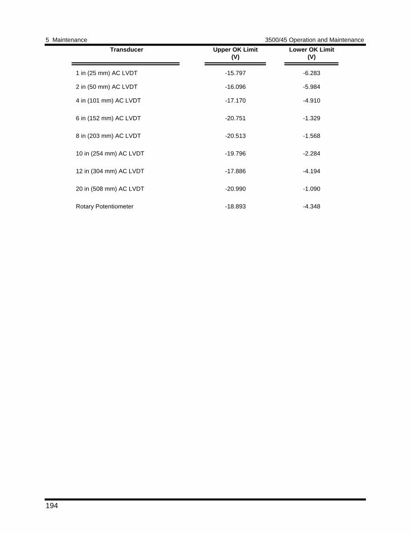
5 Maintenance 3500/45 Operation and Maintenance
194
Transducer Upper OK Limit(V)
Lower OK Limit(V)
1 in (25 mm) AC LVDT
2 in (50 mm) AC LVDT
4 in (101 mm) AC LVDT
6 in (152 mm) AC LVDT
8 in (203 mm) AC LVDT
10 in (254 mm) AC LVDT
12 in (304 mm) AC LVDT
20 in (508 mm) AC LVDT
Rotary Potentiometer
-15.797
-16.096
-17.170
-20.751
-20.513
-19.796
-17.886
-20.990
-18.893
-6.283
-5.984
-4.910
-1.329
-1.568
-2.284
-4.194
-1.090
-4.348
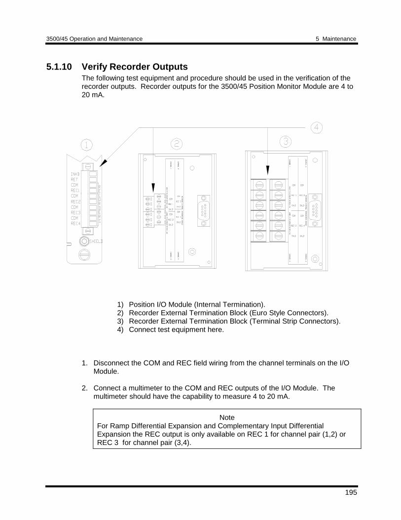
3500/45 Operation and Maintenance 5 Maintenance
195
5.1.10 Verify Recorder OutputsThe following test equipment and procedure should be used in the verification of therecorder outputs. Recorder outputs for the 3500/45 Position Monitor Module are 4 to20 mA.
1) Position I/O Module (Internal Termination).2) Recorder External Termination Block (Euro Style Connectors).3) Recorder External Termination Block (Terminal Strip Connectors).4) Connect test equipment here.
1. Disconnect the COM and REC field wiring from the channel terminals on the I/OModule.
2. Connect a multimeter to the COM and REC outputs of the I/O Module. The
multimeter should have the capability to measure 4 to 20 mA.
NoteFor Ramp Differential Expansion and Complementary Input DifferentialExpansion the REC output is only available on REC 1 for channel pair (1,2) orREC 3 for channel pair (3,4).
5 Maintenance 3500/45 Operation and Maintenance
196
3. If the proportional value is not Gap: Set the proportional value that the recorder is configured for to full-scale. (Referto the proportional value of the channel pair type you are testing in the VerifyChannel Values portion of this manual). Verify that the recorder output is reading20 mA ±1%. Go to step 4.
If the proportional value is Gap:Set the Gap proportional value to -18.00 Vdc. (Refer to the proportional value ofthe channel pair type you are testing in the Verify Channel Values portion of thismanual.) Verify that the recorder output is reading 20 mA ±1%.
4. Set the proportional value that the recorder is configured for to mid-scale. Verifythat the recorder output is reading 12 mA ±1%.
5. If you cannot verify the recorder output, the recorder configuration and
connections should be checked. If the monitor recorder output still does not verifyproperly, go to Section 5.1.11 (If a Channel Fails a Verification Test).
6. Disconnect the multimeter and reconnect the COM and REC field wiring to the
channel terminals on the I/O Module. 7. Repeat steps 1 through 6 for all configured recorder channels.
5.1.11 If a Channel Fails a Verification TestWhen handling or replacing circuit boards, always be sure to adequately protectagainst damage from Electrostatic Discharge (ESD). Always wear a proper wriststrap and work on a grounded conductive work surface.
1. Save the configuration for the module using the Rack Configuration Software. 2. Replace the module with a spare. Refer to the installation section in the 3500
Monitoring System Rack Installation and Maintenance Manual (part number129766-01).
3. Return the faulty board to Bently Nevada Corporation for repair. 4. Download the configuration for the spare module using the Rack Configuration
Software. 5. Verify the operation of the spare.
5.2 Adjusting the Scale Factor, Sensitivity, ZeroPosition, and Cross Over VoltageThis section shows how to adjust the transducer scale factor or channel sensitivity,the transducer zero position, the cross over voltages (for CIDE monitor channels),and how to implement the Direct Autozero function for Ramp Differential Expansionchannels. The Scale Factor Adjustment can be used to accommodate any deviations
3500/45 Operation and Maintenance 5 Maintenance
197
in transducer scale factor as measured on the installed transducers. The ChannelSensitivity adjustment can be used to accommodate any deviations in AC LVDTsensitivity as indicated on the calibration sheet that came with particular AC LVDTand any deviations due the field wiring. Do not use the procedure to compensate forerrors within the monitor and the I/O module. If a monitor does not meetspecifications, exchange it with a spare and return the faulty module to Bently NevadaCorporation for repair. The newly installed spare module should be properlyconfigured and tested.
Adjusting the scale factor affects the readings of all configured parametersassociated with the channel. If you change the scale factor, be sure to use the newvalue when calculating inputs for verification of channel values.
Adjusting the channel sensitivity affects the readings of all configured parametersassociated with the channel. If you change the channel sensitivity, be sure to use thenew value when calculating inputs for verification of channel values.
The Zero Position Adjustment is used for Thrust, Differential Expansion, and RampDifferential Expansion measurements. Adjust the zero position after the probe isgapped and its target is in the proper position.
Cross Over Voltage adjustment is used for Complementary Input DifferentialExpansion. Adjust the Cross Over Voltages for each channel of the channel pair afterthe probes have been gapped with the target in the proper position.
The Direct Autozero function can be used to zero offset error for the Directproportional values of Ramp Differential Expansion channels. This function can onlybe used when the full-scale voltage span is less than 3.0 Vdc.
All of the adjustment procedures consist of using the Rack Configuration Software toupload the configuration from the rack, change the scale factor, channel sensitivity,zero position, cross over voltage, or Autozero an RDE channel and the download thenew configuration back to the rack. You can adjust these settings using the followingmethods:
• enter a new value in the scale factor box on the transducer screen, in the channelsensitivity box on the transducer screen, in the zero position box or the cross overvoltage box on the Channel Options screen (or Channel Pair Options screen).
• Use Adjust and then enter a new value in the scale factor box, the zero positionbox, or the cross over voltage box. View the effect of your change by observingthe proportional value in the current values box.
• Use Adjust next to the zero position voltage box to use the Direct Autozerofunction for Ramp Differential Expansion channels.
The advantage of using the Adjust screen is that you can use the bar graphs to seethe effect of your adjustments on the output signals of the channel. The followingprocedures show how to use the methods.
5 Maintenance 3500/45 Operation and Maintenance
198
5.2.1 Adjusting the Scale Factor or Channel Sensitivity1. Connect the configuring computer to the rack using one of the methods listed in
the 3500 Monitoring System Rack Configuration and Utilities Guide (part number129777-01).
2. Run the Rack Configuration Software. 3. Initiate communication with the rack by clicking on the Connect option in the File
menu and then selecting the connection method that you used in step 1. 4. Upload the configuration from the rack by clicking on the Upload option in the File
menu. 5. Click on the Options button on the 3500 System Configuration screen. 6. Select the monitor you want to adjust. The Monitor screen will appear. 7. Select the Options button under the appropriate Channel or Channel Pair. The
configured Channel or Channel Pair Options screen will appear. 8. Select the Customize button in the Transducer Selection box. A Transducer
screen will appear. 9. Enter a value for scale factor or the channel sensitivity in the Scale Factor or
Channel Sensitivity box. If you go to the Adjust screen by selecting Adjust , besure to adjust the input to the channel away from the Zero Position so you canadjust the scale factor/channel sensitivity and see the results.
10. Return to the 3500 System Configuration screen by clicking on the OK buttons of
the successive screens. The new scale factor or channel sensitivity is now addedto the configuration for this channel.
11. Download the new configuration to the appropriate monitor by selecting
Download from the File menu. The new setting for scale factor or channelsensitivity will take effect when the “Download successful” prompt appears.
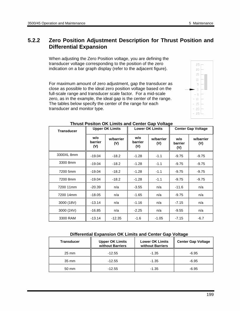
3500/45 Operation and Maintenance 5 Maintenance
199
5.2.2 Zero Position Adjustment Description for Thrust Position andDifferential Expansion
When adjusting the Zero Position voltage, you are defining thetransducer voltage corresponding to the position of the zeroindication on a bar graph display (refer to the adjacent figure).
For maximum amount of zero adjustment, gap the transducer asclose as possible to the ideal zero position voltage based on thefull-scale range and transducer scale factor. For a mid-scalezero, as in the example, the ideal gap is the center of the range.The tables below specify the center of the range for eachtransducer and monitor type.
Thrust Positon OK Limits and Center Gap Voltage
TransducerUpper OK Limits Lower OK Limits Center Gap Voltage
w/obarrier
(V)
w/barrier(V)
w/obarrier
(V)
w/barrier(V)
w/obarrier
(V)
w/barrier(V)
3300XL 8mm -19.04 -18.2 -1.28 -1.1 -9.75 -9.75
3300 8mm -19.04 -18.2 -1.28 -1.1 -9.75 -9.75
7200 5mm -19.04 -18.2 -1.28 -1.1 -9.75 -9.75
7200 8mm -19.04 -18.2 -1.28 -1.1 -9.75 -9.75
7200 11mm -20.39 n/a -3.55 n/a -11.6 n/a
7200 14mm -18.05 n/a -1.65 n/a -9.75 n/a
3000 (18V) -13.14 n/a -1.16 n/a -7.15 n/a
3000 (24V) -16.85 n/a -2.25 n/a -9.55 n/a
3300 RAM -13.14 -12.35 -1.6 -1.05 -7.15 -6.7
Differential Expansion OK Limits and Center Gap Voltage
Transducer Upper OK Limitswithout Barriers
Lower OK Limitswithout Barriers
Center Gap Voltage
25 mm -12.55 -1.35 -6.95
35 mm -12.55 -1.35 -6.95
50 mm -12.55 -1.35 -6.95
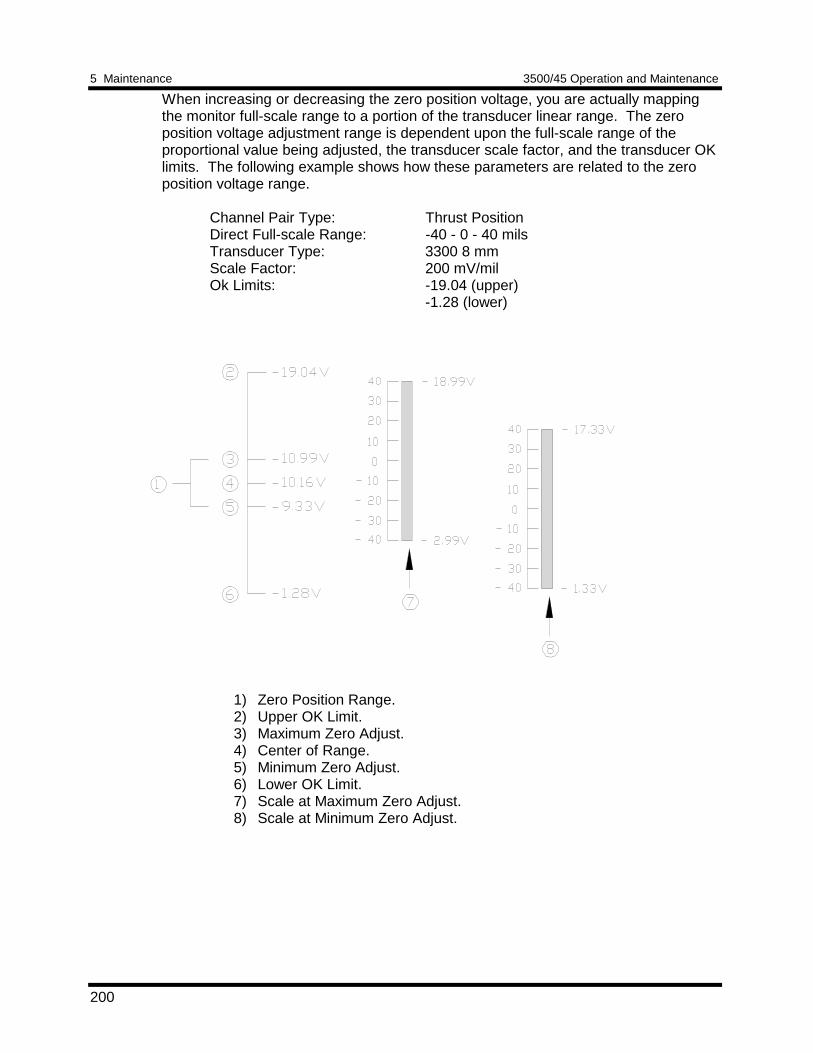
5 Maintenance 3500/45 Operation and Maintenance
200
When increasing or decreasing the zero position voltage, you are actually mappingthe monitor full-scale range to a portion of the transducer linear range. The zeroposition voltage adjustment range is dependent upon the full-scale range of theproportional value being adjusted, the transducer scale factor, and the transducer OKlimits. The following example shows how these parameters are related to the zeroposition voltage range.
Channel Pair Type: Thrust PositionDirect Full-scale Range: -40 - 0 - 40 milsTransducer Type: 3300 8 mmScale Factor: 200 mV/milOk Limits: -19.04 (upper)
-1.28 (lower)
1) Zero Position Range.2) Upper OK Limit.3) Maximum Zero Adjust.4) Center of Range.5) Minimum Zero Adjust.6) Lower OK Limit.7) Scale at Maximum Zero Adjust.8) Scale at Minimum Zero Adjust.
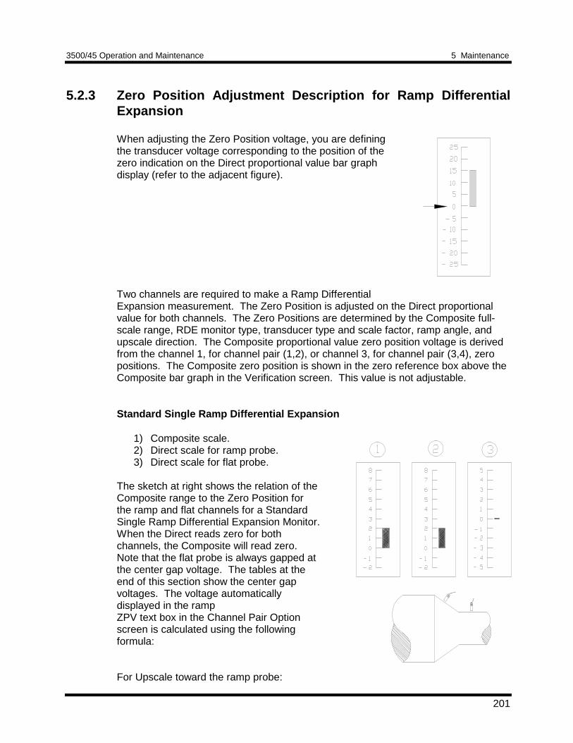
3500/45 Operation and Maintenance 5 Maintenance
201
5.2.3 Zero Position Adjustment Description for Ramp DifferentialExpansion
When adjusting the Zero Position voltage, you are definingthe transducer voltage corresponding to the position of thezero indication on the Direct proportional value bar graphdisplay (refer to the adjacent figure).
Two channels are required to make a Ramp DifferentialExpansion measurement. The Zero Position is adjusted on the Direct proportionalvalue for both channels. The Zero Positions are determined by the Composite full-scale range, RDE monitor type, transducer type and scale factor, ramp angle, andupscale direction. The Composite proportional value zero position voltage is derivedfrom the channel 1, for channel pair (1,2), or channel 3, for channel pair (3,4), zeropositions. The Composite zero position is shown in the zero reference box above theComposite bar graph in the Verification screen. This value is not adjustable.
Standard Single Ramp Differential Expansion
1) Composite scale.2) Direct scale for ramp probe.3) Direct scale for flat probe.
The sketch at right shows the relation of theComposite range to the Zero Position forthe ramp and flat channels for a StandardSingle Ramp Differential Expansion Monitor.When the Direct reads zero for bothchannels, the Composite will read zero.Note that the flat probe is always gapped atthe center gap voltage. The tables at theend of this section show the center gapvoltages. The voltage automaticallydisplayed in the rampZPV text box in the Channel Pair Optionscreen is calculated using the followingformula:
For Upscale toward the ramp probe:
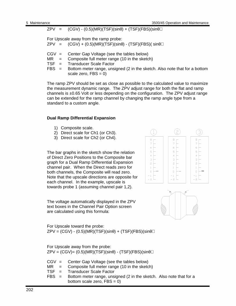
5 Maintenance 3500/45 Operation and Maintenance
202
ZPV = (CGV) - (0.5)(MR)(TSF)(sinθ) + (TSF)(FBS)(sinθ)
For Upscale away from the ramp probe:ZPV = (CGV) + (0.5)(MR)(TSF)(sinθ) - (TSF)(FBS)( sinθ)
CGV = Center Gap Voltage (see the tables below)MR = Composite full meter range (10 in the sketch)TSF = Transducer Scale FactorFBS = Bottom meter range, unsigned (2 in the sketch. Also note that for a bottom
scale zero, FBS = 0)
The ramp ZPV should be set as close as possible to the calculated value to maximizethe measurement dynamic range. The ZPV adjust range for both the flat and rampchannels is ±0.65 Volt or less depending on the configuration. The ZPV adjust rangecan be extended for the ramp channel by changing the ramp angle type from astandard to a custom angle.
Dual Ramp Differential Expansion
1) Composite scale.2) Direct scale for Ch1 (or Ch3).3) Direct scale for Ch2 (or Ch4).
The bar graphs in the sketch show the relationof Direct Zero Positions to the Composite bargraph for a Dual Ramp Differential Expansionchannel pair. When the Direct reads zero forboth channels, the Composite will read zero.Note that the upscale directions are opposite foreach channel. In the example, upscale istowards probe 1 (assuming channel pair 1,2).
The voltage automatically displayed in the ZPVtext boxes in the Channel Pair Option screenare calculated using this formula:
For Upscale toward the probe:ZPV = (CGV) - (0.5)(MR)(TSF)(sinθ) + (TSF)(FBS)(sinθ)
For Upscale away from the probe:ZPV = (CGV)= (0.5)(MR)(TSF)(sinθ) - (TSF)(FBS)(sinθ)
CGV = Center Gap Voltage (see the tables below)MR = Composite full meter range (10 in the sketch)TSF = Transducer Scale FactorFBS = Bottom meter range, unsigned (2 in the sketch. Also note that for a
bottom scale zero, FBS = 0)
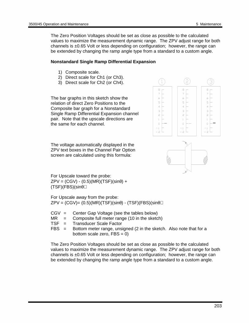
3500/45 Operation and Maintenance 5 Maintenance
203
The Zero Position Voltages should be set as close as possible to the calculatedvalues to maximize the measurement dynamic range. The ZPV adjust range for bothchannels is ±0.65 Volt or less depending on configuration; however, the range canbe extended by changing the ramp angle type from a standard to a custom angle.
Nonstandard Single Ramp Differential Expansion
1) Composite scale.2) Direct scale for Ch1 (or Ch3).3) Direct scale for Ch2 (or Ch4).
The bar graphs in this sketch show therelation of direct Zero Positions to theComposite bar graph for a NonstandardSingle Ramp Differential Expansion channelpair. Note that the upscale directions arethe same for each channel.
The voltage automatically displayed in theZPV text boxes in the Channel Pair Optionscreen are calculated using this formula:
For Upscale toward the probe:ZPV = (CGV) - (0.5)(MR)(TSF)(sinθ) +(TSF)(FBS)(sinθ)
For Upscale away from the probe:ZPV = (CGV)= (0.5)(MR)(TSF)(sinθ) - (TSF)(FBS)(sinθ)
CGV = Center Gap Voltage (see the tables below)MR = Composite full meter range (10 in the sketch)TSF = Transducer Scale FactorFBS = Bottom meter range, unsigned (2 in the sketch. Also note that for a
bottom scale zero, FBS = 0)
The Zero Position Voltages should be set as close as possible to the calculatedvalues to maximize the measurement dynamic range. The ZPV adjust range for bothchannels is ±0.65 Volt or less depending on configuration; however, the range canbe extended by changing the ramp angle type from a standard to a custom angle.
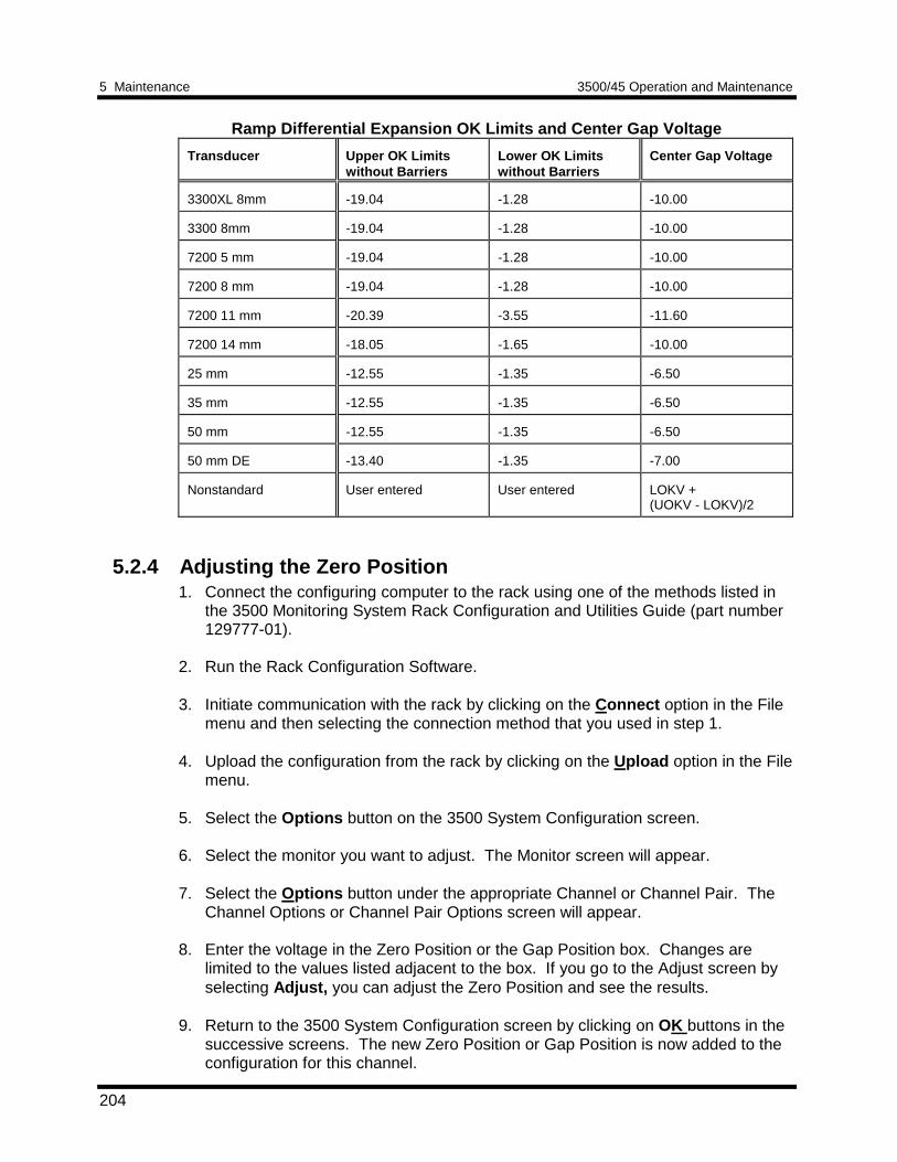
5 Maintenance 3500/45 Operation and Maintenance
204
Ramp Differential Expansion OK Limits and Center Gap Voltage
Transducer Upper OK Limitswithout Barriers
Lower OK Limitswithout Barriers
Center Gap Voltage
3300XL 8mm -19.04 -1.28 -10.00
3300 8mm -19.04 -1.28 -10.00
7200 5 mm -19.04 -1.28 -10.00
7200 8 mm -19.04 -1.28 -10.00
7200 11 mm -20.39 -3.55 -11.60
7200 14 mm -18.05 -1.65 -10.00
25 mm -12.55 -1.35 -6.50
35 mm -12.55 -1.35 -6.50
50 mm -12.55 -1.35 -6.50
50 mm DE -13.40 -1.35 -7.00
Nonstandard User entered User entered LOKV +(UOKV - LOKV)/2
5.2.4 Adjusting the Zero Position1. Connect the configuring computer to the rack using one of the methods listed in
the 3500 Monitoring System Rack Configuration and Utilities Guide (part number129777-01).
2. Run the Rack Configuration Software. 3. Initiate communication with the rack by clicking on the Connect option in the File
menu and then selecting the connection method that you used in step 1. 4. Upload the configuration from the rack by clicking on the Upload option in the File
menu.
5. Select the Options button on the 3500 System Configuration screen. 6. Select the monitor you want to adjust. The Monitor screen will appear. 7. Select the Options button under the appropriate Channel or Channel Pair. The
Channel Options or Channel Pair Options screen will appear. 8. Enter the voltage in the Zero Position or the Gap Position box. Changes are
limited to the values listed adjacent to the box. If you go to the Adjust screen byselecting Adjust, you can adjust the Zero Position and see the results.
9. Return to the 3500 System Configuration screen by clicking on OK buttons in the
successive screens. The new Zero Position or Gap Position is now added to theconfiguration for this channel.
3500/45 Operation and Maintenance 5 Maintenance
205
10. Download the new configuration to the appropriate monitor by selecting the
Download option in the File menu and then selecting the appropriate monitor.The new setting for Zero Position will take effect when the “Download successful”prompt appears.
5.2.5 Direct Autozero Function Description
The Direct Autozero function is used to reduce offset errors for Ramp DifferentialExpansion channels where the full-scale voltage span is less than 3 Volts.
For Ramp Differential Expansion channels certain combinations of full-scale range,ramp angle, and transducer type can result in small full-scale voltage spans. Forthese full-scale ranges very small offset errors in the data acquistion path can resultin excessive measurement error.
Example: Dual Ramp Differential Expansion channel pairComposite Full-scale Range: -5 mm / 0 / 5 mmRange Angle: 4 DegreesTransducers: 35 mm (scale factor = 0.7874 V/mm)
The full-scale voltage span: = sin(4°) x (0.7874 V/mm) x (10 mm)= 0.55 Volts
Use the Direct Autozero function after the probe has been gapped and secured at thezero position voltage, the transducers are connected to the monitor in their finaloperating connections, and the 3500 monitor rack has been warmed up for at leastone-half hour in its normal operating environment. You will need at least a 4 ½ digitmultimeter. The multimeter is used to measure the transducer input voltage. Youmust make a Direct connection to the rack using the Rack Configuration Software toperform the procedure.
5.2.6 Procedure for Direct Autozero
1. Connect the configuring computer to the rack using the Direct connection methodlisted in the 3500 Monitoring System Rack Configuration and Utilities Guide (partnumber 129777-01).
2. Run the Rack Configuration Software. 3. Initiate communication with the rack by clicking on the Connect option in the File
menu. Select the Direct connection method. 4. Upload the configuration from the rack by clicking on the Upload option in the File
menu. 5. Select the Options button on the 3500 System Configuration screen. 6. Select the Position monitor you want to adjust. The Monitor screen will appear.
5 Maintenance 3500/45 Operation and Maintenance
206
7. Select the Options button under the appropriate Ramp Differential ExpansionChannel Pair. The Channel Pair Options screen will appear.
8. Verify that the probe is gapped so that the actual transducer voltage for the
channel you are adjusting is set within the zero position adjustment range listedbeneath the Zero Position Voltage box. Changes are limited to the adjustmentrange.
9. Select Adjust next to the Zero Position Voltage box. The ZPV Adjust screen will
appear. 10. Measure the transducer input voltage with the digital multimeter. Enter the
measured zero position voltage in the Direct ZPV box. Make sure you enter thevalue to 0.001 Volt resolution.
11. Select the Direct Autozero button. A dialog box will appear. Read the
information in the dialog box and select Yes if you are ready to continue. 12. Verify that the Direct bar graph and the Direct current value box is reading 0.00
within the applicable tolerance. See section 5.1.6.3 (Verify Channel Values -Ramp Differential Expansion).
13. Return to the 3500 System Configuration screen by clicking on OK buttons in the
successive screens. The Autozero adjustment is now added to the configurationfor this channel.
14. Download the new configuration to the appropriate monitor by selecting the
Download option in the File menu and then selecting the appropriate monitor.The new Autozero adjustment will take effect when the “Download successful”prompt appears.
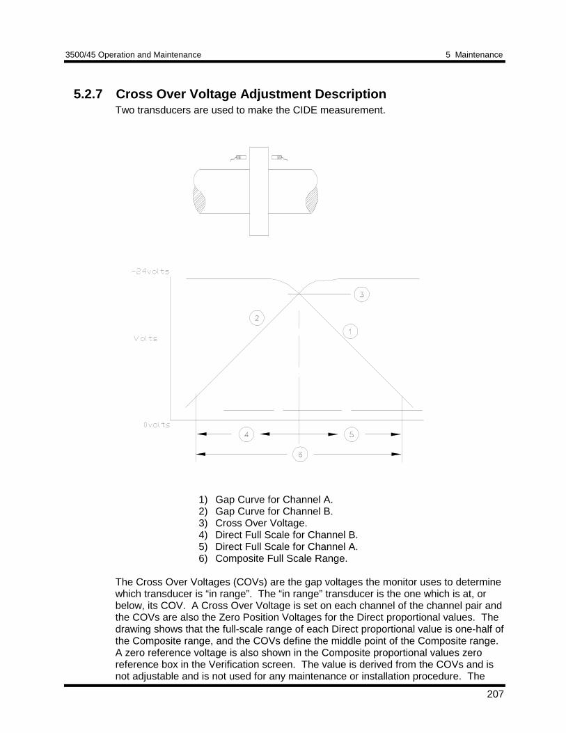
3500/45 Operation and Maintenance 5 Maintenance
207
5.2.7 Cross Over Voltage Adjustment DescriptionTwo transducers are used to make the CIDE measurement.
1) Gap Curve for Channel A.2) Gap Curve for Channel B.3) Cross Over Voltage.4) Direct Full Scale for Channel B.5) Direct Full Scale for Channel A.6) Composite Full Scale Range.
The Cross Over Voltages (COVs) are the gap voltages the monitor uses to determinewhich transducer is “in range”. The “in range” transducer is the one which is at, orbelow, its COV. A Cross Over Voltage is set on each channel of the channel pair andthe COVs are also the Zero Position Voltages for the Direct proportional values. Thedrawing shows that the full-scale range of each Direct proportional value is one-half ofthe Composite range, and the COVs define the middle point of the Composite range.A zero reference voltage is also shown in the Composite proportional values zeroreference box in the Verification screen. The value is derived from the COVs and isnot adjustable and is not used for any maintenance or installation procedure. The
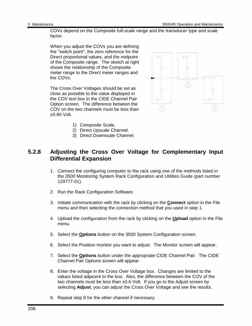
5 Maintenance 3500/45 Operation and Maintenance
208
COVs depend on the Composite full-scale range and the transducer type and scalefactor.
When you adjust the COVs you are definingthe “switch point”, the zero reference for theDirect proportional values, and the midpointof the Composite range. The sketch at rightshows the relationship of the Compositemeter range to the Direct meter ranges andthe COVs.
The Cross Over Voltages should be set asclose as possible to the value displayed inthe COV text box in the CIDE Channel PairOption screen. The difference between theCOV on the two channels must be less than±0.60 Volt.
1) Composite Scale.2) Direct Upscale Channel.3) Direct Downscale Channel.
5.2.8 Adjusting the Cross Over Voltage for Complementary InputDifferential Expansion
1. Connect the configuring computer to the rack using one of the methods listed inthe 3500 Monitoring System Rack Configuration and Utilities Guide (part number129777-01).
2. Run the Rack Configuration Software. 3. Initiate communication with the rack by clicking on the Connect option in the File
menu and then selecting the connection method that you used in step 1. 4. Upload the configuration from the rack by clicking on the Upload option in the File
menu. 5. Select the Options button on the 3500 System Configuration screen. 6. Select the Position monitor you want to adjust. The Monitor screen will appear. 7. Select the Options button under the appropriate CIDE Channel Pair. The CIDE
Channel Pair Options screen will appear. 8. Enter the voltage in the Cross Over Voltage box. Changes are limited to the
values listed adjacent to the box. Also, the difference between the COV of thetwo channels must be less than ±0.6 Volt. If you go to the Adjust screen byselecting Adjust , you can adjust the Cross Over Voltage and see the results.
9. Repeat step 8 for the other channel if necessary.
3500/45 Operation and Maintenance 5 Maintenance
209
10. Return to the 3500 System Configuration screen by clicking on OK buttons in thesuccessive screens. The new Cross Over Voltage is now added to theconfiguration for this channel.
11. Download the new configuration to the appropriate monitor by selecting theDownload option in the File menu and then selecting the appropriate monitor.The new setting for Cross Over Voltage will take effect when the “Downloadsuccessful” prompt appears.
5.3 Adjusting the Upscale and Downscale Voltagefor Case ExpansionThe sensitivity of the 24765 DC LVDT can vary as must as ±15%. The sensitivity ofAC LVDTs with field wiring can vary as much as 20%. If you use a 24765 DC LVDT oran AC LVDT to measure case expansion, install the LVDT and then use thisprocedure to adjust the upscale and downscale voltage for the channel. If you use the135613 HT DC LVDT, it is not normally necessary to perform this procedure.
To adjust the Upscale and Downscale Voltages:1. Connect the configuring computer to the rack using one of the methods listed in
the 3500 Monitoring System Rack Configuration and Utilities Guide (part number129777-01).
2. Run the Rack Configuration Software. 3. Initiate communication with the rack by clicking on the Connect option in the File
menu and then selecting the connection method that you used in step 1. 4. Upload the configuration from the rack by clicking on the Upload option in the File
menu. 5. Click on the Options button on the 3500 System configuration screen. 6. Select the monitor you want to adjust. The Monitor screen will appear. 7. Select the Options button under the appropriate Channel or Channel Pair. The
configured Channel or Channel Pair Options screen will appear. 8. Select the Customize button in the Transducer Selection box. A Transducer
screen will appear.
9. Select the Adjust button. The Adjust screen for the selected channel will appear. 10. Loosen and adjust the LVDT or core mounting components such that the core
position can be adjusted manually throughout the entire expansion range.
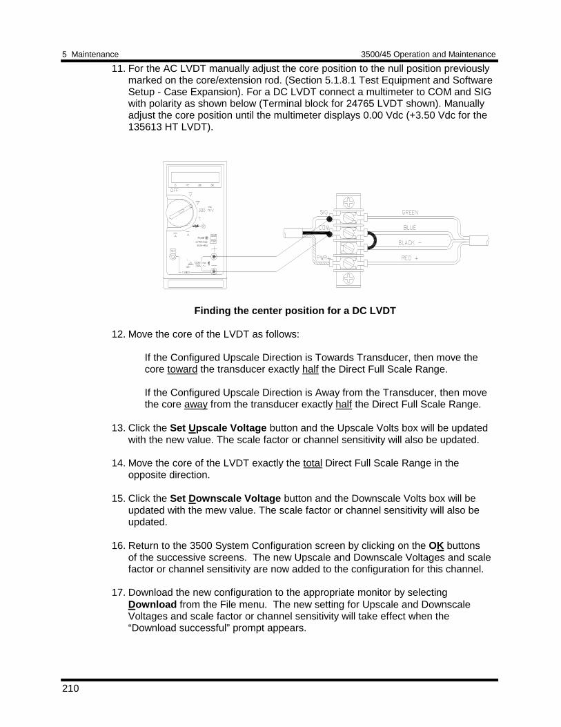
5 Maintenance 3500/45 Operation and Maintenance
210
11. For the AC LVDT manually adjust the core position to the null position previouslymarked on the core/extension rod. (Section 5.1.8.1 Test Equipment and SoftwareSetup - Case Expansion). For a DC LVDT connect a multimeter to COM and SIGwith polarity as shown below (Terminal block for 24765 LVDT shown). Manuallyadjust the core position until the multimeter displays 0.00 Vdc (+3.50 Vdc for the135613 HT LVDT).
Finding the center position for a DC LVDT
12. Move the core of the LVDT as follows:
If the Configured Upscale Direction is Towards Transducer, then move thecore toward the transducer exactly half the Direct Full Scale Range.
If the Configured Upscale Direction is Away from the Transducer, then movethe core away from the transducer exactly half the Direct Full Scale Range.
13. Click the Set Upscale Voltage button and the Upscale Volts box will be updated
with the new value. The scale factor or channel sensitivity will also be updated. 14. Move the core of the LVDT exactly the total Direct Full Scale Range in the
opposite direction. 15. Click the Set Downscale Voltage button and the Downscale Volts box will be
updated with the mew value. The scale factor or channel sensitivity will also beupdated.
16. Return to the 3500 System Configuration screen by clicking on the OK buttons
of the successive screens. The new Upscale and Downscale Voltages and scalefactor or channel sensitivity are now added to the configuration for this channel.
17. Download the new configuration to the appropriate monitor by selectingDownload from the File menu. The new setting for Upscale and DownscaleVoltages and scale factor or channel sensitivity will take effect when the“Download successful” prompt appears.
3500/45 Operation and Maintenance 5 Maintenance
211
5.4 Adjusting the Upscale and Downscale Voltagefor Valve PositionInstall the AC LVDT or the Rotary Potentiometer (Refer to Section 5.1.9 ValvePosition Channels).Then use this procedure to adjust the upscale and downscalevoltage for the channel. Note: You must have downloaded an initial configuration,including an appropriate stroke length before you can adjust the Upscale andDownscale Voltages.
To adjust the Upscale and Downscale Voltages:
1. Connect the configuring computer to the rack using one of the methods listed inthe 3500 Monitoring System Rack Configuration and Utilities Guide (part number129777-01).
2. Run the Rack Configuration Software. 3. Initiate communication with the rack by clicking on the Connect option in the File
menu and then selecting the connection method that you used in step 1. 4. Upload the configuration from the rack by clicking on the Upload option in the File
menu. 5. Click on the Options button on the 3500 System configuration screen. 6. Select the monitor you want to adjust. The Monitor screen will appear.
7. Select the Options button under the appropriate Channel. The configuredChannel Options screen will appear.
9. Select the Customize button in the Transducer Selection box. A Transducer
screen will appear.
10. Select the Adjust button. The Adjust screen for the selected channel will appear.
11. With the valve at one of it’s endpoint positions (either fully open or fully closed)click the appropriate Set Upscale Voltage or Set Downscale Voltage button andthe appropriate Volts box will be updated with the new value. The scale factor orchannel sensitivity will also be updated.
12. Stroke the valve (move the valve to its opposite endpoint position, i.e. if the valvewas fully opened, close it; if the valve was fully closed, open it.)
13. Set the opposite full scale voltage endpoint from that which was set in step 11above using a similar method as that in step 11. The appropriate Volts box will beupdated. The scale factor or channel sensitivity will also be updated.
14. Return to the 3500 System Configuration screen by clicking on the OK buttonsof the successive screens. The new Upscale and Downscale Voltages and thescale factor or channel sensitivity are now added to the configuration for thischannel.
5 Maintenance 3500/45 Operation and Maintenance
212
15. Download the new configuration to the appropriate monitor by selectingDownload from the File menu. The new setting for Upscale and DownscaleVoltages and the scale factor or channel sensitivity will take effect when the“Download successful” prompt appears.
16. Stroke the valve again while viewing the Verification screen to verify the fullupscale and full downscale voltages.
5.5 Performing Firmware UpgradesOccasionally it may be necessary to replace the original firmware that is shipped with the3500/45 Position Monitor. The following instructions describe how to remove the existingfirmware and replace it with upgrade firmware. The monitor will need to be reconfiguredusing the 3500 Rack Configuration software after having its firmware upgraded.
The Following items will be required to perform a firmware upgrade to the monitor:Large Flathead ScrewdriverGrounding Wrist Strap*IC Removal Tool*Upgrade Firmware IC*
*Refer to Section 7 (Ordering Information) for part numbers. Users may use their owngrounding wrist strap or IC removal tool.
5.5.1 Installation ProcedureThe following steps should be followed to complete the monitor firmware upgrade(Detailed instructions for some of the steps listed below are provided on the followingpages. Please review completely before proceeding.):
Ensure that the monitor’s configuration is saved using the 3500 RackConfiguration software.
Refer to 1.2 (Handling and Storing Considerations) before handling the monitor orthe upgrade firmware IC.
Remove the monitor from the 3500 Rack.
Remove the Top Shield from the monitor.
Remove the original firmware IC from the monitor PWA.
Install the upgrade firmware IC into the socket on the monitor PWA.
Replace the monitor Top Shield.
Install the upgrade firmware IC into the socket on the monitor PWA.
Replace the monitor Top Shield.
Replace the monitor into the 3500 system.
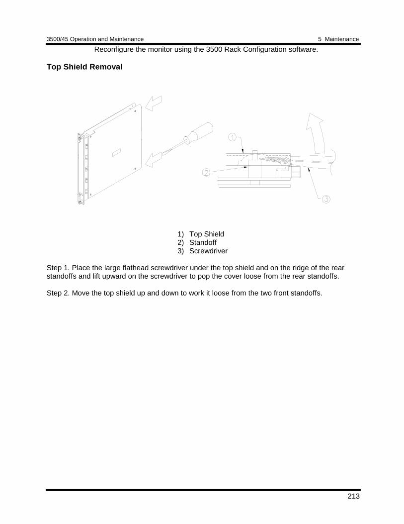
3500/45 Operation and Maintenance 5 Maintenance
213
Reconfigure the monitor using the 3500 Rack Configuration software.
Top Shield Removal
1) Top Shield2) Standoff3) Screwdriver
Step 1. Place the large flathead screwdriver under the top shield and on the ridge of the rearstandoffs and lift upward on the screwdriver to pop the cover loose from the rear standoffs.
Step 2. Move the top shield up and down to work it loose from the two front standoffs.
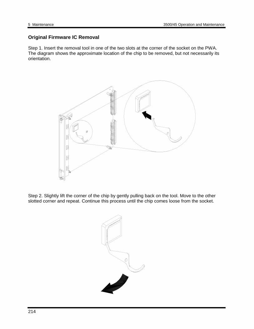
5 Maintenance 3500/45 Operation and Maintenance
214
Original Firmware IC Removal
Step 1. Insert the removal tool in one of the two slots at the corner of the socket on the PWA.The diagram shows the approximate location of the chip to be removed, but not necessarily itsorientation.
Step 2. Slightly lift the corner of the chip by gently pulling back on the tool. Move to the otherslotted corner and repeat. Continue this process until the chip comes loose from the socket.
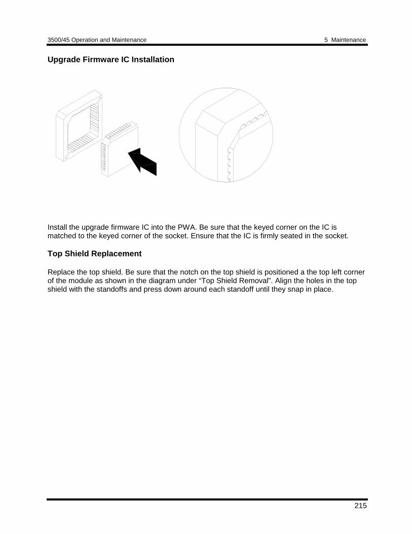
3500/45 Operation and Maintenance 5 Maintenance
215
Upgrade Firmware IC Installation
Install the upgrade firmware IC into the PWA. Be sure that the keyed corner on the IC ismatched to the keyed corner of the socket. Ensure that the IC is firmly seated in the socket.
Top Shield Replacement
Replace the top shield. Be sure that the notch on the top shield is positioned a the top left cornerof the module as shown in the diagram under “Top Shield Removal”. Align the holes in the topshield with the standoffs and press down around each standoff until they snap in place.
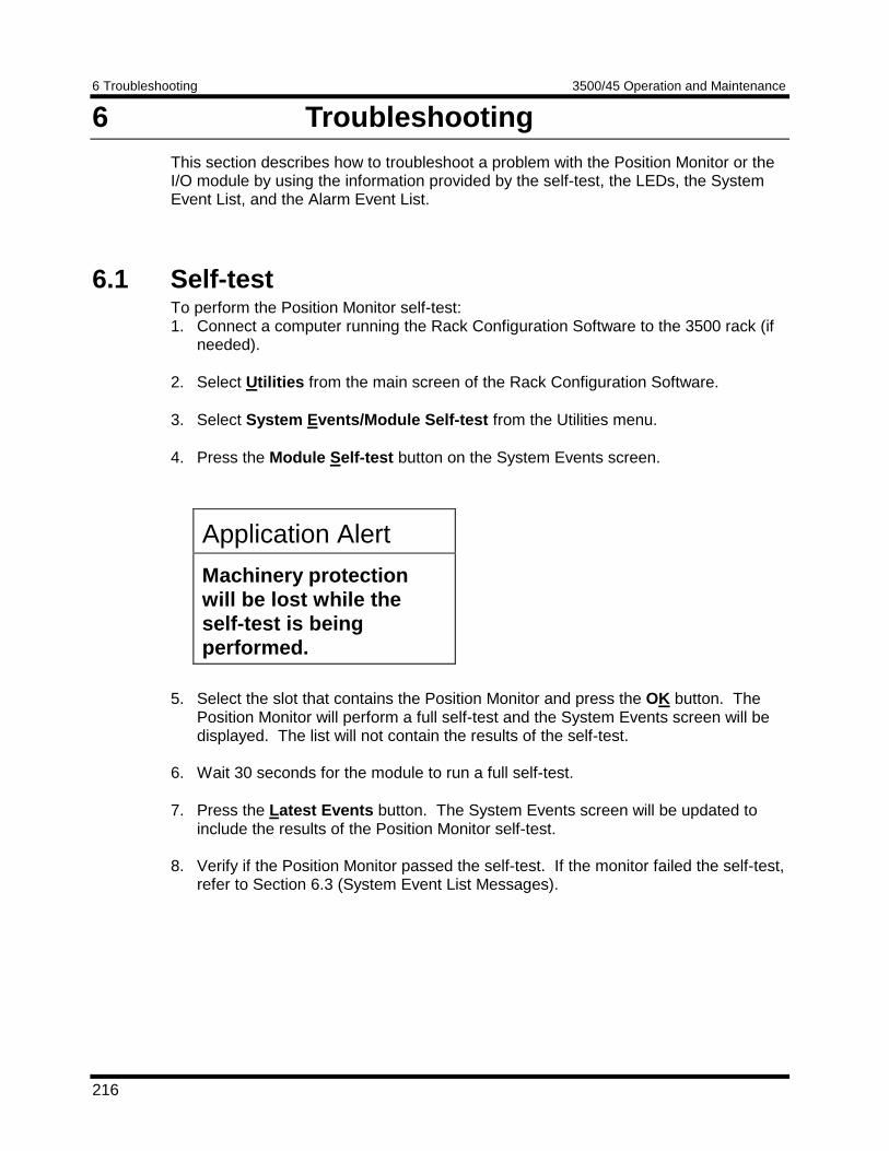
6 Troubleshooting 3500/45 Operation and Maintenance
216
6 TroubleshootingThis section describes how to troubleshoot a problem with the Position Monitor or theI/O module by using the information provided by the self-test, the LEDs, the SystemEvent List, and the Alarm Event List.
6.1 Self-testTo perform the Position Monitor self-test:1. Connect a computer running the Rack Configuration Software to the 3500 rack (if
needed). 2. Select Utilities from the main screen of the Rack Configuration Software. 3. Select System Events/Module Self-test from the Utilities menu. 4. Press the Module Self-test button on the System Events screen.
5. Select the slot that contains the Position Monitor and press the OK button. ThePosition Monitor will perform a full self-test and the System Events screen will bedisplayed. The list will not contain the results of the self-test.
6. Wait 30 seconds for the module to run a full self-test. 7. Press the Latest Events button. The System Events screen will be updated to
include the results of the Position Monitor self-test. 8. Verify if the Position Monitor passed the self-test. If the monitor failed the self-test,
refer to Section 6.3 (System Event List Messages).
Application Alert
Machinery protectionwill be lost while theself-test is beingperformed.
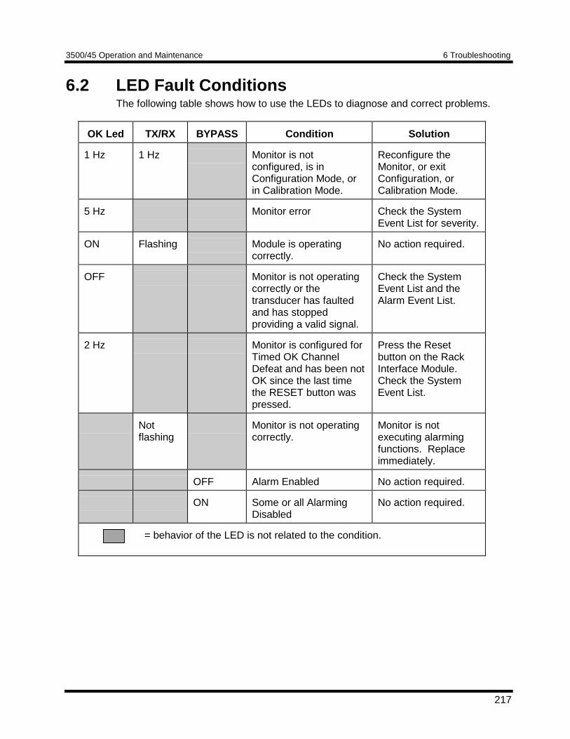
3500/45 Operation and Maintenance 6 Troubleshooting
217
6.2 LED Fault ConditionsThe following table shows how to use the LEDs to diagnose and correct problems.
OK Led TX/RX BYPASS Condition Solution
1 Hz 1 Hz Monitor is notconfigured, is inConfiguration Mode, orin Calibration Mode.
Reconfigure theMonitor, or exitConfiguration, orCalibration Mode.
5 Hz Monitor error Check the SystemEvent List for severity.
ON Flashing Module is operatingcorrectly.
No action required.
OFF Monitor is not operatingcorrectly or thetransducer has faultedand has stoppedproviding a valid signal.
Check the SystemEvent List and theAlarm Event List.
2 Hz Monitor is configured forTimed OK ChannelDefeat and has been notOK since the last timethe RESET button waspressed.
Press the Resetbutton on the RackInterface Module.Check the SystemEvent List.
Notflashing
Monitor is not operatingcorrectly.
Monitor is notexecuting alarmingfunctions. Replaceimmediately.
OFF Alarm Enabled No action required.
ON Some or all AlarmingDisabled
No action required.
= behavior of the LED is not related to the condition.
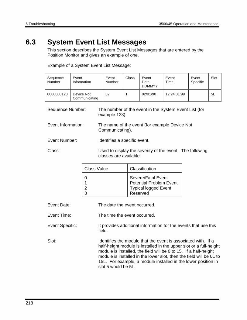
6 Troubleshooting 3500/45 Operation and Maintenance
218
6.3 System Event List MessagesThis section describes the System Event List Messages that are entered by thePosition Monitor and gives an example of one.
Example of a System Event List Message:
SequenceNumber
EventInformation
EventNumber
Class EventDateDDMMYY
EventTime
EventSpecific
Slot
0000000123 Device NotCommunicating
32 1 02/01/90 12:24:31:99 5L
Sequence Number: The number of the event in the System Event List (forexample 123).
Event Information: The name of the event (for example Device NotCommunicating).
Event Number: Identifies a specific event.
Class: Used to display the severity of the event. The followingclasses are available:
Class Value Classification
0123
Severe/Fatal EventPotential Problem EventTypical logged EventReserved
Event Date: The date the event occurred.
Event Time: The time the event occurred.
Event Specific: It provides additional information for the events that use thisfield.
Slot: Identifies the module that the event is associated with. If ahalf-height module is installed in the upper slot or a full-heightmodule is installed, the field will be 0 to 15. If a half-heightmodule is installed in the lower slot, then the field will be 0L to15L. For example, a module installed in the lower position inslot 5 would be 5L.
3500/45 Operation and Maintenance 6 Troubleshooting
219
The following System Event List Messages may be placed in the list by the PositionMonitor and are listed in numerical order. If an event marked with a star (*) occurs, thePosition Monitor will stop alarming. If you are unable to solve any problems, contactyour nearest Bently Nevada Corporation office.
Flash Memory FailureEvent Number: 11Event Classification: Severe/FatalAction: Replace the Monitor Module as soon as possible.
EEPROM Memory FailureEvent Number: 13Event Classification: Severe/Fatal or Potential ProblemAction: Replace the Monitor Module as soon as possible.
Device Not CommunicatingEvent Number: 32Event Classification: Potential ProblemAction: Check to see if one of the following components is faulty:
• the Monitor Module• the rack backplane
Device Is CommunicatingEvent Number: 33Event Classification: Potential ProblemAction: Check to see if one of the following components is faulty:
• the Monitor Module• the rack backplane
* Neuron FailureEvent Number: 34Event Classification: Severe / Fatal EventAction: Replace the Monitor Module immediately.
Monitor Module will stop alarming.
* I/O Module MismatchEvent Number: 62Event Classification: Severe / Fatal EventAction: Verify that the type of I/O module installed matches what was selected in
the software. If the correct I/O module is installed, there may be a faultwith the Monitor Module or the Monitor I/O module.Monitor Module will stop alarming.
6 Troubleshooting 3500/45 Operation and Maintenance
220
I/O Module CompatibleEvent Number: 63Event Classification: Severe / Fatal EventAction: Verify that the type of I/O module installed matches what was selected in
the software. If the correct I/O module is installed, there may be a faultwith the Monitor Module or the Monitor I/O module.
* Fail I/O Jumper CheckEvent Number: 64Event Classification: Severe / Fatal EventAction: Verify that the type of I/O module installed matches what was selected in
the software. If the correct I/O module is installed, there may be a faultwith the Monitor Module or the Monitor I/O module.Monitor Module will stop alarming.
Pass I/O Jumper CheckEvent Number: 65Event Classification: Severe / Fatal EventAction: Verify that the type of I/O module installed matches what was selected in
the software. If the correct I/O module is installed, there may be a faultwith the Monitor Module or the Monitor I/O module.
Fail Main Board +5V-A (Fail Main Board +5V - upper Power Supply)Event Number: 100Event Classification: Potential ProblemAction: Verify that noise from the power source is not causing the problem. If the
problem is not caused by noise, check to see if one of the followingcomponents is faulty:• the Monitor Module• the Power Supply installed in the upper slot
Pass Main Board +5V-A (Pass Main Board +5V - upper Power Supply)Event Number: 101Event Classification: Potential ProblemAction: Verify that noise from the power source is not causing the problem. If the
problem is not caused by noise, check to see if one of the followingcomponents is faulty:• the Monitor Module• the Power Supply installed in the upper slot
3500/45 Operation and Maintenance 6 Troubleshooting
221
Fail Main Board +5V-B (Fail Main Board +5V - lower Power Supply)Event Number: 102Event Classification: Potential ProblemAction: Verify that noise from the power source is not causing the problem. If the
problem is not caused by noise, check to see if one of the followingcomponents is faulty:• the Monitor Module• the Power Supply installed in the lower slot
Pass Main Board +5V-B (Pass Main Board +5V - lower Power Supply)Event Number: 103Event Classification: Potential ProblemAction: Verify that noise from the power source is not causing the problem. If the
problem is not caused by noise, check to see if one of the followingcomponents is faulty:• the Monitor Module• the Power Supply installed in the lower slot
* Fail Main Board +5V-AB (Fail Main Board +5V - upper and lower PowerSupplies)
Event Number: 104Event Classification: Severe/Fatal EventAction: Verify that noise from the power source is not causing the problem. If the
problem is not caused by noise, check to see if one of the followingcomponents is faulty:• the Monitor Module• the Power Supply installed in the upper slot• the Power Supply installed in the lower slotMonitor Module will stop alarming.
Pass Main Board +5V-AB (Pass Main Board +5V - upper and lower PowerSupplies)
Event Number: 105Event Classification: Severe/Fatal EventAction: Verify that noise from the power source is not causing the problem. If the
problem is not caused by noise, check to see if one of the followingcomponents is faulty:• the Monitor Module• the Power Supply installed in the upper slot• the Power Supply installed in the lower slot
6 Troubleshooting 3500/45 Operation and Maintenance
222
Fail Main Board +15V-A (Fail Main Board +15V - upper Power Supply)Event Number: 106Event Classification: Potential ProblemAction: Verify that noise from the power source is not causing the problem. If the
problem is not caused by noise, check to see if one of the followingcomponents is faulty:• the Monitor Module• the Power Supply installed in the upper slot
Pass Main Board +15V-A (Pass Main Board +15V - upper Power Supply)Event Number: 107Event Classification: Potential ProblemAction: Verify that noise from the power source is not causing the problem. If the
problem is not caused by noise, check to see if one of the followingcomponents is faulty:• the Monitor Module• the Power Supply installed in the upper slot
Fail Main Board +15V-B (Fail Main Board +15V - lower Power Supply)Event Number: 108Event Classification: Potential ProblemAction: Verify that noise from the power source is not causing the problem. If the
problem is not caused by noise, check to see if one of the followingcomponents is faulty:• the Monitor Module• the Power Supply installed in the lower slot
Pass Main Board +15V-B (Pass Main Board +15V - lower Power Supply)Event Number: 109Event Classification: Potential ProblemAction: Verify that noise from the power source is not causing the problem. If the
problem is not caused by noise, check to see if one of the followingcomponents is faulty:• the Monitor Module• the Power Supply installed in the lower slot
3500/45 Operation and Maintenance 6 Troubleshooting
223
* Fail Main Board +15V-AB (Fail Main Board +15V - upper and lower PowerSupplies)
Event Number: 110Event Classification: Severe/Fatal EventAction: Verify that noise from the power source is not causing the problem. If the
problem is not caused by noise, check to see if one of the followingcomponents is faulty:• the Monitor Module• the Power Supply installed in the upper slot• the Power Supply installed in the lower slotMonitor Module will stop alarming.
Pass Main Board +15V-AB (Pass Main Board +15V - upper and lower PowerSupplies)
Event Number: 111Event Classification: Severe/Fatal EventAction: Verify that noise from the power source is not causing the problem. If the
problem is not caused by noise, check to see if one of the followingcomponents is faulty:• the Monitor Module• the Power Supply installed in the upper slot• the Power Supply installed in the lower slot
Fail Main Board -24V-A (Fail Main Board -24V - upper Power Supply)Event Number: 112Event Classification: Potential ProblemAction: Verify that noise from the power source is not causing the problem. If the
problem is not caused by noise, check to see if one of the followingcomponents is faulty:• the Monitor Module• the Power Supply installed in the upper slot
Pass Main Board -24V-A (Pass Main Board -24V - upper Power Supply)Event Number: 113Event Classification: Potential ProblemAction: Verify that noise from the power source is not causing the problem. If the
problem is not caused by noise, check to see if one of the followingcomponents is faulty:• the Monitor Module• the Power Supply installed in the upper slot
6 Troubleshooting 3500/45 Operation and Maintenance
224
Fail Main Board -24V-B (Fail Main Board -24V - lower Power Supply)Event Number: 114Event Classification: Potential ProblemAction: Verify that noise from the power source is not causing the problem. If the
problem is not caused by noise, check to see if one of the followingcomponents is faulty:• the Monitor Module• the Power Supply installed in the lower slot
Pass Main Board -24V-B (Pass Main Board -24V - lower Power Supply)Event Number: 115Event Classification: Potential ProblemAction: Verify that noise from the power source is not causing the
problem. If the problem is not caused by noise, check to see if one ofthe following components is faulty:• the Monitor Module• the Power Supply installed in the lower slot
* Fail Main Board -24V-AB (Fail Main Board -24V - upper and lower PowerSupplies)
Event Number: 116Event Classification: Severe/Fatal EventAction: Verify that noise from the power source is not causing the problem. If the
problem is not caused by noise, check to see if one of the followingcomponents is faulty:• the Monitor Module• the Power Supply installed in the upper slot• the Power Supply installed in the lower slotMonitor Module will stop alarming.
Pass Main Board -24V-AB (Pass Main Board -24V - upper and lower PowerSupplies)
Event Number: 117Event Classification: Severe/Fatal EventAction: Verify that noise from the power source is not causing the problem. If the
problem is not caused by noise, check to see if one of the followingcomponents is faulty:• the Monitor Module• the Power Supply installed in the upper slot• the Power Supply installed in the lower slot
3500/45 Operation and Maintenance 6 Troubleshooting
225
Fail Main Board +5VA-A (Fail Main Board +5V Analog - upper Power Supply)Event Number: 122Event Classification: Potential ProblemAction: Verify that noise from the power source is not causing the problem. If the
problem is not caused by noise, check to see if one of the followingcomponents is faulty:• the Monitor Module• the Power Supply installed in the upper slot
Pass Main Board +5VA-A (Pass Main Board +5V Analog - upper Power Supply)Event Number: 123Event Classification: Potential ProblemAction: Verify that noise from the power source is not causing the problem. If the
problem is not caused by noise, check to see if one of the followingcomponents is faulty:• the Monitor Module• the Power Supply installed in the upper slot
Fail Main Board +5VA-B (Fail Main Board +5V Analog - lower Power Supply)Event Number: 124Event Classification: Potential ProblemAction: Verify that noise from the power source is not causing the problem. If the
problem is not caused by noise, check to see if one of the followingcomponents is faulty:• the Monitor Module• the Power Supply installed in the lower slot
Pass Main Board +5VA-B (Pass Main Board +5V Analog - lower Power Supply)Event Number: 125Event Classification: Potential ProblemAction: Verify that noise from the power source is not causing the problem. If
the problem is not caused by noise, check to see if one of the followingcomponents is faulty:• the Monitor Module• the Power Supply installed in the lower slot
6 Troubleshooting 3500/45 Operation and Maintenance
226
* Fail Main Board +5VA-AB (Fail Main Board +5V Analog - upper and lower PowerSupplies)
Event Number: 126Event Classification: Severe/Fatal EventAction: Verify that noise from the power source is not causing the problem. If the
problem is not caused by noise, check to see if one of the followingcomponents is faulty:• the Monitor Module• the Power Supply installed in the upper slot• the Power Supply installed in the lower slotMonitor Module will stop alarming.
Pass Main Board +5VA-AB (Pass Main Board +5V Analog - upper and lower PowerSupplies)
Event Number: 127Event Classification: Severe/Fatal EventAction: Verify that noise from the power source is not causing the problem. If the
problem is not caused by noise, check to see if one of the followingcomponents is faulty:• the Monitor Module• the Power Supply installed in the upper slot• the Power Supply installed in the lower slot
* Configuration FailureEvent Number: 301Event Classification: Severe/Fatal EventAction: Download a new configuration to the Monitor Module. If the problem still
exists, replace the Monitor Module immediately.Monitor Module will stop alarming.
Configuration FailureEvent Number: 301Event Classification: Potential ProblemAction: Download a new configuration to the Monitor Module. If the problem still
exists, replace the Monitor Module as soon as possible.
* Module Entered Cfg Mode (Module Entered Configuration Mode)Event Number: 302Event Classification: Typical Logged EventAction: No action required.
Monitor Module will stop alarming.
3500/45 Operation and Maintenance 6 Troubleshooting
227
Software Switches ResetEvent Number: 305Event Classification: Potential Problem or Typical Logged EventAction: Download the software switches to the Monitor Module. If the software
switches are not correct, replace the Monitor Module as soon aspossible.
Internal Cal Reset (Internal Calibration Reset)Event Number: 307Event Classification: Severe/Fatal EventEvent Specific: Ch pair xAction: Replace Monitor Module immediately.
Monitor TMR PPL Failed (Monitor TMR Proportional value Failed)Event Number: 310Event Classification: Potential ProblemAction: Replace the Monitor Module.
Monitor TMR PPL Passed (Monitor TMR Proportional value Passed)Event Number: 311Event Classification: Potential ProblemAction: Replace the Monitor Module.
Module RebootEvent Number: 320Event Classification: Typical Logged EventAction: No action required.
* Module Removed from RackEvent Number: 325Event Classification: Typical Logged EventAction: No action required.
Monitor Module will stop alarming.
Module Inserted in RackEvent Number: 326Event Classification: Typical Logged EventAction: No action required.
Device Events LostEvent Number: 355Event Classification: Typical Logged EventAction: No action required.
This may be due to the removal of the Rack Interface Module for anextended period of time.
6 Troubleshooting 3500/45 Operation and Maintenance
228
Module Alarms LostEvent Number: 356Event Classification: Typical Logged EventAction: No action required.
This may be due to the removal of the Rack Interface Module for anextended period of time.
* Module Entered Calibr. (Module Entered Calibration Mode)Event Number: 365Event Classification: Typical Logged EventAction: No action required.
Monitor Module will stop alarming.
Module Exited Calibr. (Module Exited Calibration Mode)Event Number: 366Event Classification: Typical Logged EventAction: No action required.
Pass Module Self-testEvent Number: 410Event Classification: Typical Logged EventAction: No action required.
* Enabled Ch Bypass (Enabled Channel Bypass)Event Number: 416Event Classification: Typical logged eventEvent Specific: Ch xAction: No action required.
Alarming has been inhibited by this action.
Disabled Ch Bypass (Disabled Channel Bypass)Event Number: 417Event Classification: Typical logged eventEvent Specific: Ch xAction: No action required.
* Enabled Alert BypassEvent Number: 420Event Classification: Typical logged eventEvent Specific: Ch xAction: No action required.
Alarming has been inhibited by this action.
3500/45 Operation and Maintenance 6 Troubleshooting
229
Disabled Alert BypassEvent Number: 421Event Classification: Typical logged eventEvent Specific: Ch xAction: No action required.
* Enabled Danger BypassEvent Number: 422Event Classification: Typical logged eventEvent Specific: Ch xAction: No action required.
Alarming has been inhibited by this action.
Disabled Danger BypassEvent Number: 423Event Classification: Typical logged eventEvent Specific: Ch xAction: No action required.
* Enabled Special Inh (Enabled Special Inhibit)Event Number: 424Event Classification: Typical logged eventEvent Specific: Ch xAction: No action required.
Alarming has been inhibited by this action.
Disabled Special Inh (Disabled Special Inhibit)Event Number: 425Event Classification: Typical logged eventEvent Specific: Ch xAction: No action required.
* Enabled Mon Alarm Bypass (Enabled monitor alarm bypass)Event Number: 426Event Classification: Typical logged eventAction: No action required.
Monitor Module will stop alarming.
Disabled Mon Alarm Bypass (Disabled monitor alarm bypass)Event Number: 427Event Classification: Typical logged eventAction: No action required.
6 Troubleshooting 3500/45 Operation and Maintenance
230
Enabled Direct PPL (Enabled the Direct proportional value for a Ramp orComplementary Input Differential Expansion Channel usingthe software channel switch)
Event Number: 428Event Classification: Typical logged eventEvent Specific: Ch xAction: No action required.
Disabled Direct PPL (Disabled the Direct proportional value for a Ramp orComplementary Input Differential Expansion Channel usingthe software channel switch)
Event Number: 429Event Classification: Typical logged eventEvent Specific: Ch xAction: No action required.
* Fail Slot Id TestEvent Number: 461Event Classification: Severe/Fatal EventAction: Verify that the Monitor Module is fully inserted in the rack. If the Monitor
Module is installed correctly, check to see if one of the followingcomponents is faulty:• the Monitor Module• the rack backplaneMonitor Module will stop alarming.
Pass Slot Id TestEvent Number: 462Event Classification: Severe/Fatal EventAction: Verify that the Monitor Module is fully inserted in the rack. If the Monitor
Module is installed correctly, check to see if one of the followingcomponents is faulty:• the Monitor Module• the rack backplane
* Enabled Test SignalEvent Number: 481Event Classification: Typical logged eventAction: No action required.
Monitor Module will stop alarming.
Disabled Test SignalEvent Number: 482Event Classification: Typical logged eventAction: No action required.
3500/45 Operation and Maintenance 6 Troubleshooting
231
DSP Reset AttemptedEvent Number: 501Event Classification: Severe / Fatal EventEvent Specific: Ch pair xAction: If the message is seen repeatedly in the System Event List, then replace
the Monitor Module immediately.
* DSP Self-test FailureEvent Number: 502Event Classification: Severe / Fatal EventEvent Specific: Ch pair xAction: Replace the Monitor Module immediately.
Monitor Module will stop alarming.
Fail I/O +15V-A (Fail I/O Module +15V - upper Power Supply)Event Number: 554Event Classification: Potential ProblemAction: Verify that noise from the power source is not causing the problem. If
the problem is not caused by noise, check to see if one of the followingcomponents is faulty:• the I/O Module• the Monitor Module• the Power Supply installed in the upper slot
Pass I/O +15V-A (Pass I/O Module +15V - upper Power Supply)Event Number: 555Event Classification: Potential ProblemAction: Verify that noise from the power source is not causing the problem. If
the problem is not caused by noise, check to see if one of the followingcomponents is faulty:• the I/O Module• the Monitor Module• the Power Supply installed in the upper slot
Fail I/O +15V-B (Fail I/O Module +15V - lower Power Supply)Event Number: 556Event Classification: Potential ProblemAction: Verify that noise from the power source is not causing the problem. If
the problem is not caused by noise, check to see if one of the followingcomponents is faulty:• the I/O Module• the Monitor Module• the Power Supply installed in the lower slot
6 Troubleshooting 3500/45 Operation and Maintenance
232
Pass I/O +15V-B (Pass I/O Module +15V - lower Power Supply)Event Number: 557Event Classification: Potential ProblemAction: Verify that noise from the power source is not causing the problem. If
the problem is not caused by noise, check to see if one of the followingcomponents is faulty:• the I/O Module• the Monitor Module• the Power Supply installed in the lower slot
* Fail I/O +15V-AB (Fail I/O Module +15V - upper and lower PowerSupplies)
Event Number: 558Event Classification: Severe/Fatal EventAction: Verify that noise from the power source is not causing the problem. If
the problem is not caused by noise, check to see if one of the followingcomponents is faulty:• the I/O Module• the Monitor Module• the Power Supply installed in the upper slot• the Power Supply installed in the lower slot
Pass I/O +15V-AB (Pass I/O Module +15V - upper and lower PowerSupplies)
Event Number: 559Event Classification: Severe/Fatal EventAction: Verify that noise from the power source is not causing the problem. If
the problem is not caused by noise, check to see if one of the followingcomponents is faulty:• the I/O Module• the Monitor Module• the Power Supply installed in the upper slot• the Power Supply installed in the lower slot
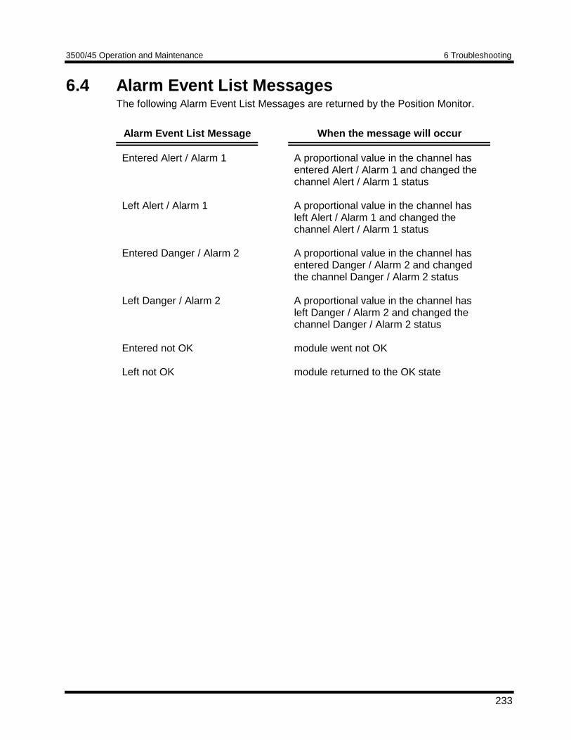
3500/45 Operation and Maintenance 6 Troubleshooting
233
6.4 Alarm Event List MessagesThe following Alarm Event List Messages are returned by the Position Monitor.
Alarm Event List Message When the message will occur
Entered Alert / Alarm 1
Left Alert / Alarm 1
Entered Danger / Alarm 2
Left Danger / Alarm 2
Entered not OK
Left not OK
A proportional value in the channel hasentered Alert / Alarm 1 and changed thechannel Alert / Alarm 1 status
A proportional value in the channel hasleft Alert / Alarm 1 and changed thechannel Alert / Alarm 1 status
A proportional value in the channel hasentered Danger / Alarm 2 and changedthe channel Danger / Alarm 2 status
A proportional value in the channel hasleft Danger / Alarm 2 and changed thechannel Danger / Alarm 2 status
module went not OK
module returned to the OK state
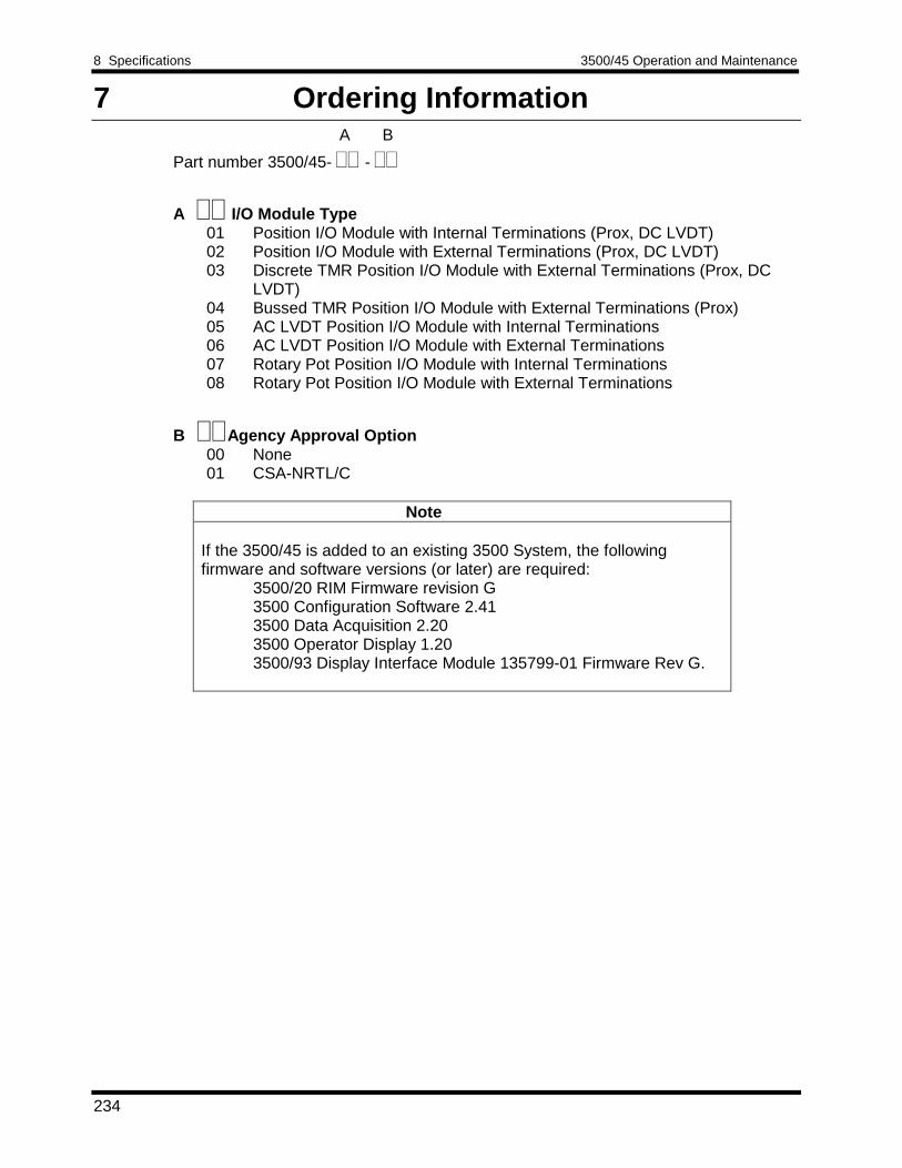
8 Specifications 3500/45 Operation and Maintenance
234
7 Ordering Information
A I/O Module Type01 Position I/O Module with Internal Terminations (Prox, DC LVDT)02 Position I/O Module with External Terminations (Prox, DC LVDT)03 Discrete TMR Position I/O Module with External Terminations (Prox, DC
LVDT)04 Bussed TMR Position I/O Module with External Terminations (Prox)05 AC LVDT Position I/O Module with Internal Terminations06 AC LVDT Position I/O Module with External Terminations07 Rotary Pot Position I/O Module with Internal Terminations08 Rotary Pot Position I/O Module with External Terminations
B Agency Approval Option00 None01 CSA-NRTL/C
Note
If the 3500/45 is added to an existing 3500 System, the followingfirmware and software versions (or later) are required:
3500/20 RIM Firmware revision G3500 Configuration Software 2.413500 Data Acquisition 2.203500 Operator Display 1.203500/93 Display Interface Module 135799-01 Firmware Rev G.
A B
Part number 3500/45- -
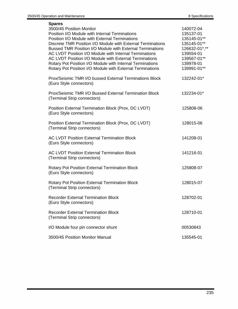
3500/45 Operation and Maintenance 8 Specifications
235
Spares3500/45 Position Monitor 140072-04Position I/O Module with Internal Terminations 135137-01Position I/O Module with External Terminations 135145-01**Discrete TMR Position I/O Module with External Terminations 135145-01**Bussed TMR Position I/O Module with External Terminations 126632-01*,**AC LVDT Position I/O Module with Internal Terminations 139554-01AC LVDT Position I/O Module with External Terminations 139567-01**Rotary Pot Position I/O Module with Internal Terminations 139978-01Rotary Pot Position I/O Module with External Terminations 139991-01**
Prox/Seismic TMR I/O bussed External Terminations Block 132242-01*(Euro Style connectors)
Prox/Seismic TMR I/O Bussed External Termination Block 132234-01*(Terminal Strip connectors)
Position External Termination Block (Prox, DC LVDT) 125808-06(Euro Style connectors)
Position External Termination Block (Prox, DC LVDT) 128015-06(Terminal Strip connectors)
AC LVDT Position External Termination Block 141208-01(Euro Style connectors)
AC LVDT Position External Termination Block 141216-01(Terminal Strip connectors)
Rotary Pot Position External Termination Block 125808-07(Euro Style connectors)
Rotary Pot Position External Termination Block 128015-07(Terminal Strip connectors)
Recorder External Termination Block 128702-01(Euro Style connectors)
Recorder External Termination Block 128710-01(Terminal Strip connectors)
I/O Module four pin connector shunt 00530843
3500/45 Position Monitor Manual 135545-01
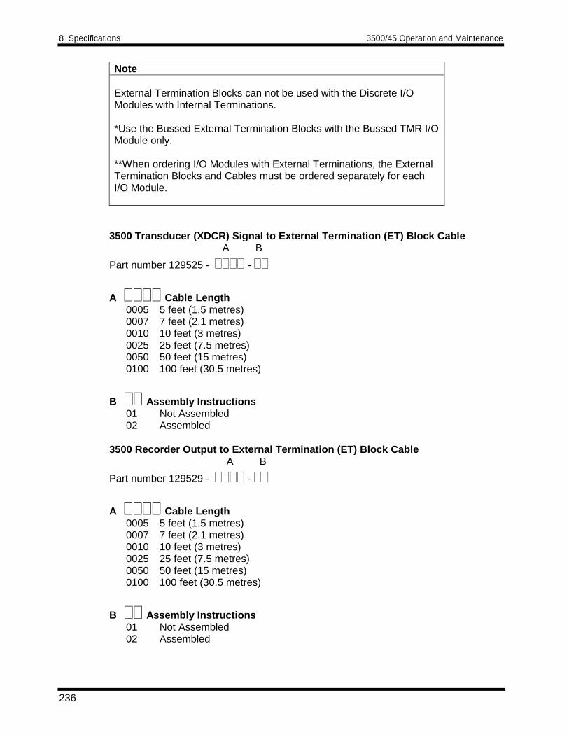
8 Specifications 3500/45 Operation and Maintenance
236
Note
External Termination Blocks can not be used with the Discrete I/OModules with Internal Terminations.
*Use the Bussed External Termination Blocks with the Bussed TMR I/OModule only.
**When ordering I/O Modules with External Terminations, the ExternalTermination Blocks and Cables must be ordered separately for eachI/O Module.
3500 Transducer (XDCR) Signal to External Termination (ET) Block CableA B
Part number 129525 - -
A Cable Length0005 5 feet (1.5 metres)0007 7 feet (2.1 metres)0010 10 feet (3 metres)0025 25 feet (7.5 metres)0050 50 feet (15 metres)0100 100 feet (30.5 metres)
B Assembly Instructions01 Not Assembled02 Assembled
3500 Recorder Output to External Termination (ET) Block CableA B
Part number 129529 - -
A Cable Length0005 5 feet (1.5 metres)0007 7 feet (2.1 metres)0010 10 feet (3 metres)0025 25 feet (7.5 metres)0050 50 feet (15 metres)0100 100 feet (30.5 metres)
B Assembly Instructions01 Not Assembled02 Assembled
3500/45 Operation and Maintenance 8 Specifications
237
8 Specifications
INPUTS
Signal: Accepts from 1 to 4 signal inputs.
Input Impedance: 10 kΩ (Proximitor)1 MΩ (DC LVDT)137 kΩ (AC LVDT)200 kΩ (Rotary Pot)
Power: 7.7 watts using Position I/O.8.5 Watts typical using AC LVDT I/O5.6 Watts typical using Rotary Pot I/O
Sensitivity:
Thrust: 3.94 mV/µm (100 mV/mil) or7.87 mV/µm (200 mV/mil)
Differential Expansion: 0.394 V/mm (10 mV/mil) or0.787 V/mm (20 mV/mil)
Ramp Differential Expansion:0.394 V/mm (10 mV/mil) or0.787 V/mm (20 mV/mil) or3.94 V/mm (100 mV/mil) or7.874 V/mm (200 mV/mil)
Complementary Input Differential Expansion:0.394 V/mm (10 mV/mil) or0.787 V/mm (20 mV/mil) or3.94 V/mm (100 mV/mil)
Case Expansion:DC LVDTs (when used with +15 Vdc supply):
0.05 V/mm (1.25 mV/mil) or0.08 V/mm (2.10 mV/mil) or0.10 V/mm (2.50 mV/mil) or0.20 V/mm (5.00 mV/mil) or0.21 V/mm (5.40 mV/mil) or0.24 V/mm (6.00 mV/mil)
AC LVDTs:28.74 mV/V/mm (0.73mV/V/mil) or15.35 mV/V/mm (0.39 mV/V/mil) or9.45 mV/V/mm (0.24 mV/V/mil)
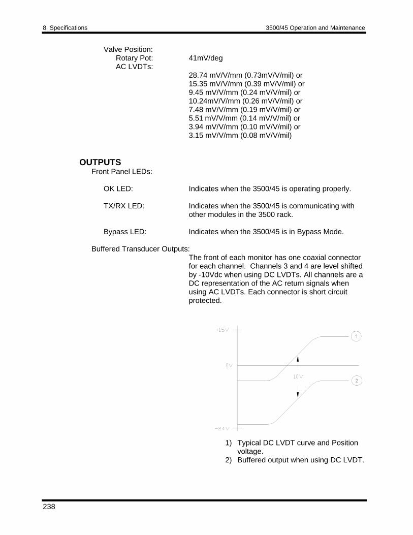
8 Specifications 3500/45 Operation and Maintenance
238
Valve Position:Rotary Pot: 41mV/degAC LVDTs:
28.74 mV/V/mm (0.73mV/V/mil) or15.35 mV/V/mm (0.39 mV/V/mil) or9.45 mV/V/mm (0.24 mV/V/mil) or10.24mV/V/mm (0.26 mV/V/mil) or7.48 mV/V/mm (0.19 mV/V/mil) or5.51 mV/V/mm (0.14 mV/V/mil) or3.94 mV/V/mm (0.10 mV/V/mil) or3.15 mV/V/mm (0.08 mV/V/mil)
OUTPUTSFront Panel LEDs:
OK LED: Indicates when the 3500/45 is operating properly.
TX/RX LED: Indicates when the 3500/45 is communicating withother modules in the 3500 rack.
Bypass LED: Indicates when the 3500/45 is in Bypass Mode.
Buffered Transducer Outputs:The front of each monitor has one coaxial connectorfor each channel. Channels 3 and 4 are level shiftedby -10Vdc when using DC LVDTs. All channels are aDC representation of the AC return signals whenusing AC LVDTs. Each connector is short circuitprotected.
1) Typical DC LVDT curve and Positionvoltage.
2) Buffered output when using DC LVDT.
3500/45 Operation and Maintenance 8 Specifications
239
Buffered Transducer Output Impedance: 550 Ω ( Proximitor, DC LVDTs)
Transducer Power Supply: -24 Vdc (Proximitor)+15 Vdc (DC LVDT)-12.38Vdc (with Rotary Pot connected) 3.3 Vrms, 3400 Hz sine wave (AC LVDT)
Recorder: +4 to +20 mA. Values are proportional to monitor fullscale. Individual recorder values are provided foreach channel except Ramp and CIDE. Monitoroperation is unaffected by short circuits on recorderoutputs.
Recorder Voltage Compliance (current output):0 to +12 Vdc range across load. Load resistance is 0to 600 Ω.
Resolution 0.3662 µA per bit± 0.25% error at room temperature± 0.7% error over temperature rangeupdate rate 100 ms or less
SIGNAL CONDITIONINGSpecified at +25o C (77o F)
Thrust and Differential Expansion:Frequency Response:
Direct Filter: -3 dB at 1.2 Hz.Gap Filter: -3 dB at 0.41 Hz.
Accuracy: Within ± 0.33% of full scale typical, ± 1%maximum.
Case Expansion:Frequency Response:
Direct Filter: -3 dB at 1.2 Hz.Position Filter: -3 dB at 0.41 Hz.
Accuracy: Within ± 0.33% of full scale typical, ± 1%maximum.
Valve Position:Frequency Response:
Direct Filter: -3 dB at 1.2 Hz.Position Filter: -3 dB at 0.41 Hz.
Accuracy: Within ± 0.33% of full scale typical, ± 1%maximum.
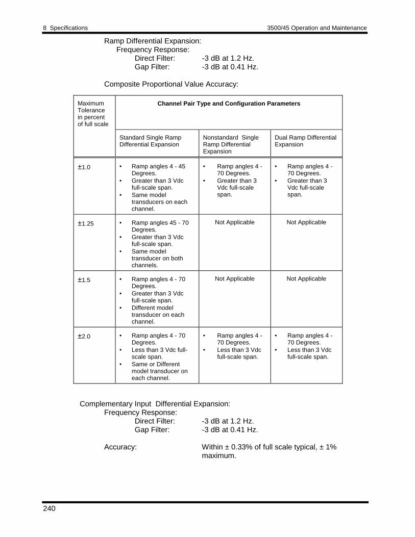
8 Specifications 3500/45 Operation and Maintenance
240
Ramp Differential Expansion:Frequency Response:
Direct Filter: -3 dB at 1.2 Hz.Gap Filter: -3 dB at 0.41 Hz.
Composite Proportional Value Accuracy:
MaximumTolerancein percentof full scale
Channel Pair Type and Configuration Parameters
Standard Single RampDifferential Expansion
Nonstandard SingleRamp DifferentialExpansion
Dual Ramp DifferentialExpansion
±1.0 • Ramp angles 4 - 45Degrees.
• Greater than 3 Vdcfull-scale span.
• Same modeltransducers on eachchannel.
• Ramp angles 4 -70 Degrees.
• Greater than 3Vdc full-scalespan.
• Ramp angles 4 -70 Degrees.
• Greater than 3Vdc full-scalespan.
±1.25 • Ramp angles 45 - 70Degrees.
• Greater than 3 Vdcfull-scale span.
• Same modeltransducer on bothchannels.
Not Applicable Not Applicable
±1.5 • Ramp angles 4 - 70Degrees.
• Greater than 3 Vdcfull-scale span.
• Different modeltransducer on eachchannel.
Not Applicable Not Applicable
±2.0 • Ramp angles 4 - 70Degrees.
• Less than 3 Vdc full-scale span.
• Same or Differentmodel transducer oneach channel.
• Ramp angles 4 -70 Degrees.
• Less than 3 Vdcfull-scale span.
• Ramp angles 4 -70 Degrees.
• Less than 3 Vdcfull-scale span.
Complementary Input Differential Expansion:Frequency Response:
Direct Filter: -3 dB at 1.2 Hz.Gap Filter: -3 dB at 0.41 Hz.
Accuracy: Within ± 0.33% of full scale typical, ± 1%maximum.
3500/45 Operation and Maintenance 8 Specifications
241
ALARMSAlarm Setpoints: Alert setpoints can be set on the following values:
Thrust: Direct and GapDifferential Expansion: Direct and GapRamp Differential Expansion: Composite andGapCIDE: CompositeCase Expansion - Paired: Direct and CompositeCase Expansion - Single: DirectValve Position: Direct
Danger setpoints can be set on the following values:Thrust: Direct and GapDifferential Expansion: Direct and GapRamp Differential Expansion: CompositeCIDE: CompositeCase Expansion - Paired: Direct and CompositeCase Expansion - Single: DirectValve Position: Direct
All alarm setpoints are set using software configuration.Alarms are adjustable and can normally be set from 0 to100% of Full Scale for each measured value. However, thereare setpoint limits based on transducer type. In some casesthe combination of full scale range and zero position voltagecan cause the full scale or bottom scale voltage to exceedthe setpoint limit. In this case the setpoint range is restrictedand does not include the entire measurement range.Accuracy of alarms are to within 0.13% of the desired value.
Alarm Time Delays: Alarm delays can be programmed using software, and canbe set as follows:
Alert: From 1 to 60 seconds in 1 second intervalsDanger: 0.1 seconds (typical) or from 1 to 60 seconds in 1 second
intervals
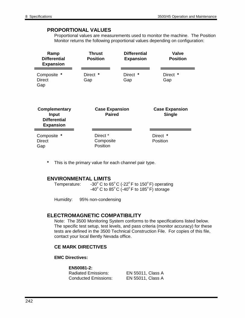
8 Specifications 3500/45 Operation and Maintenance
242
PROPORTIONAL VALUESProportional values are measurements used to monitor the machine. The PositionMonitor returns the following proportional values depending on configuration:
RampDifferentialExpansion
ThrustPosition
DifferentialExpansion
ValvePosition
Composite *DirectGap
Direct *Gap
Direct *Gap
Direct *Gap
ComplementaryInput
DifferentialExpansion
Case ExpansionPaired
Case ExpansionSingle
Composite *DirectGap
Direct *CompositePosition
Direct *Position
* This is the primary value for each channel pair type.
ENVIRONMENTAL LIMITSTemperature: -30o C to 65o C (-22o F to 150o F) operating
-40o C to 85o C (-40o F to 185o F) storage
Humidity: 95% non-condensing
ELECTROMAGNETIC COMPATIBILITYNote: The 3500 Monitoring System conforms to the specifications listed below.The specific test setup, test levels, and pass criteria (monitor accuracy) for thesetests are defined in the 3500 Technical Construction File. For copies of this file,contact your local Bently Nevada office.
CE MARK DIRECTIVES
EMC Directives:
EN50081-2:Radiated Emissions: EN 55011, Class AConducted Emissions: EN 55011, Class A
3500/45 Operation and Maintenance 8 Specifications
243
EN50082-2:Electrostatic Discharge: EN 61000-4-2, Criteria BRadiated Susceptibility: ENV 50140, Criteria AConducted Susceptibility: ENV 50141, Criteria A
Electrical Fast Transient: EN 61000-4-4, Criteria BSurge Capability: EN 61000-4-5, Criteria BMagnetic Field: EN 61000-4-8, Criteria A
Power Supply Dip: EN 61000-4-11, Criteria BRadio Telephone: ENV 50204, Criteria B
Low Voltage Directives:Safety Requirements: EN61010-1
HAZARDOUS AREA APPROVALSCSA-NRTL/C:When used with Class I, Division 2, Groups A through DInternal/External TerminationI/O Modules
PHYSICALMonitor Module:
Dimensions (Height x Width x Depth):241.3 mm x 24.4 mm x 241.8 mm(9.50 in x 0.96 in x 9.52 in)
Weight: 0.91 kg (2.0 lbs)
I/O Modules:Dimensions (Height x Width x Depth):
241.3 mm x 24.4 mm x 99.1 mm(9.50 in x 0.96 in x 3.90 in)
Weight: 0.45 kg (1.0 lb.)
RACK SPACE REQUIREMENTSMain Board: 1 full-height front slot
I/O Modules: 1 full-height rear slot