Embed Size (px)
Citation preview
OWNER’S MANUAL & OPERATING INSTRUCTIONS
10006 Santa Fe Springs RoadSanta Fe Springs CA 90670
USA / 1 (877) 338-0999www.championpowerequipment.com
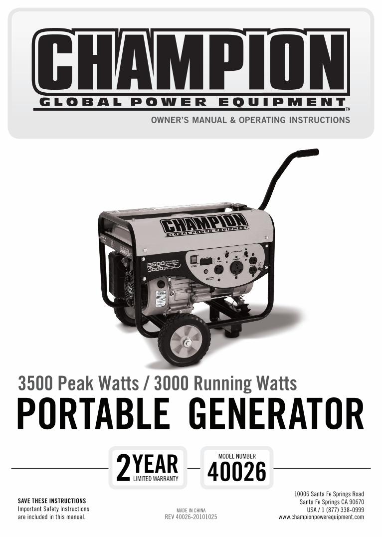
3500 Peak Watts / 3000 Running Watts
PORTABLE GENERATOR
sAvE THEsE INsTRuCTIONsImportant Safety Instructionsare included in this manual.
MADE IN CHINAREV 40026-20101025
40026MODEL NUMBER
2yEARLIMITED WARRANTY

Have questions or need assistance?Do not return this product to the store!
WE ARE HERE TO HELP!Visit our website:
www.championpowerequipment.comfor more info:
• Product Info & Updates• Frequently Asked Questions
• Tech Bulletins• Product Registration
– or –
Call our Customer Care Team Toll-Free at:
1-877-338-0999
40026
PORTABLE GENERATORTABLE Of CONTENTsIntroduction . . . . . . . . . . . . . . . . . . . . . . . . . . . . 1
Introduction . . . . . . . . . . . . . . . . . . . . . . . . . . 1Portable Power Generator . . . . . . . . . . . . . . . . . 1Accessories . . . . . . . . . . . . . . . . . . . . . . . . . . 1This Booklet . . . . . . . . . . . . . . . . . . . . . . . . . . 1
Manual Conventions . . . . . . . . . . . . . . . . . . . . . . . 2Safety Rules . . . . . . . . . . . . . . . . . . . . . . . . . . . . 3Controls and Features . . . . . . . . . . . . . . . . . . . . . 5
Generator . . . . . . . . . . . . . . . . . . . . . . . . . . . . 5Power Panel . . . . . . . . . . . . . . . . . . . . . . . . . . 6Parts Included . . . . . . . . . . . . . . . . . . . . . . . . 7
Wheel Kit . . . . . . . . . . . . . . . . . . . . . . . . . . 7Spark Arrester Kit . . . . . . . . . . . . . . . . . . . . 7Other . . . . . . . . . . . . . . . . . . . . . . . . . . . . 7
Assembly . . . . . . . . . . . . . . . . . . . . . . . . . . . . . . 8Remove the Generator from the Shipping Carton . 8Install the Wheel Kit . . . . . . . . . . . . . . . . . . . . 8Install the Support Leg . . . . . . . . . . . . . . . . . . 8Install the Handles . . . . . . . . . . . . . . . . . . . . . 8Install the Spark Arrester . . . . . . . . . . . . . . . . . 9Add Engine Oil . . . . . . . . . . . . . . . . . . . . . . . . 9Add Fuel . . . . . . . . . . . . . . . . . . . . . . . . . . . 10Grounding . . . . . . . . . . . . . . . . . . . . . . . . . . 10
Operation . . . . . . . . . . . . . . . . . . . . . . . . . . . . . 11Generator Location . . . . . . . . . . . . . . . . . . . . 11Grounding . . . . . . . . . . . . . . . . . . . . . . . . . . 11Surge Protection . . . . . . . . . . . . . . . . . . . . . . 11Starting the Engine . . . . . . . . . . . . . . . . . . . . 11Connecting Electrical Loads . . . . . . . . . . . . . . 11Stopping the Engine . . . . . . . . . . . . . . . . . . . 12Do Not Overload Generator . . . . . . . . . . . . . . . 12
Capacity . . . . . . . . . . . . . . . . . . . . . . . . . 12Power Management . . . . . . . . . . . . . . . . . . 12
Wattage Reference Chart . . . . . . . . . . . . . . . . 12
Maintenance and Storage . . . . . . . . . . . . . . . . . . 13Engine Maintenance . . . . . . . . . . . . . . . . . . . 13
Oil . . . . . . . . . . . . . . . . . . . . . . . . . . . . . 13Spark Plugs . . . . . . . . . . . . . . . . . . . . . . . 13Air Filter . . . . . . . . . . . . . . . . . . . . . . . . . 13Spark Arrester . . . . . . . . . . . . . . . . . . . . . 14Cleaning . . . . . . . . . . . . . . . . . . . . . . . . . 14Adjustments . . . . . . . . . . . . . . . . . . . . . . . 14Maintenance Schedule . . . . . . . . . . . . . . . . 14
Generator Maintenance . . . . . . . . . . . . . . . . . 15Storage . . . . . . . . . . . . . . . . . . . . . . . . . . . . 15
Generator Storage . . . . . . . . . . . . . . . . . . . 15Specifications . . . . . . . . . . . . . . . . . . . . . . . . . . 16
Engine Specifications . . . . . . . . . . . . . . . . . . 16Generator Specifications . . . . . . . . . . . . . . . . 16Fuel . . . . . . . . . . . . . . . . . . . . . . . . . . . . . . 16Oil . . . . . . . . . . . . . . . . . . . . . . . . . . . . . . . 16Spark Plugs . . . . . . . . . . . . . . . . . . . . . . . . . 16Valve Clearance . . . . . . . . . . . . . . . . . . . . . . . 16Parts Diagram . . . . . . . . . . . . . . . . . . . . . . . . 17Parts List . . . . . . . . . . . . . . . . . . . . . . . . . . . 18Wiring Diagram . . . . . . . . . . . . . . . . . . . . . . . 19
Troubleshooting . . . . . . . . . . . . . . . . . . . . . . . . . 20Warranty . . . . . . . . . . . . . . . . . . . . . . . . . . . . . 21
Warranty Qualifications . . . . . . . . . . . . . . . . . 21Repair/Replacement Warranty . . . . . . . . . . . . . 21Do Not Return The Unit ToThe Place Of Purchase . . . . . . . . . . . . . . . . . . 21Warranty Exclusions . . . . . . . . . . . . . . . . . . . . 21
Normal Wear . . . . . . . . . . . . . . . . . . . . . . 21Installation, Use and Maintenance . . . . . . . . 21Other Exclusions . . . . . . . . . . . . . . . . . . . . 21Limits of Implied Warranty and Consequential Damage . . . . . . . . . . . . . . . . . . . . . . . . . . 21
Contact Information . . . . . . . . . . . . . . . . . . . . 21Address . . . . . . . . . . . . . . . . . . . . . . . . . . 21Customer Service . . . . . . . . . . . . . . . . . . . 21Technical Service . . . . . . . . . . . . . . . . . . . 21
Emission Control System Warranty . . . . . . . . . . 22
3500 Peak Watts / 3000 Running Watts
1 REV 40026-20101025
ENGLISH 40026
IntroductionCongratulations on your purchase of a Champion
Power Equipment generator . CPE designs and builds
generators to strict specifications . With proper use and
maintenance, this generator will bring years of satisfying
service .
Portable Power GeneratorThis unit is a gasoline engine driven, alternating current
(AC) generator . It is designed to supply electrical power
for lighting, appliances, tools and similar equipment .
Record the model and serial numbers as well as date and place of purchase for future reference . Have this
information available when ordering parts and when making technical or warranty inquiries .
AccessoriesChampion Power Equipment manufactures and sells
accessories designed to help you get the most from
your purchase . To find out more about our covers, power
cables and storm kits, please visit our web site at:
www.championpowerequipment.com
This BookletEvery effort has been made to ensure the accuracy and
completeness of the information in this manual . We reserve
the right to change, alter and/or improve the product and
this document at any time without prior notice .
Champion Power Equipment support
Model Number
Serial Number
Date of Purchase
Purchase Location
1 (877) 338-0999
40026
For Oil Type see ‘Add Engine Oil‘ section . For Fuel Type see ‘Add Fuel‘ section .
INTROduCTION
REV 40026-20101025 2
40026 ENGLISH
This manual uses the following symbols to help differentiate between different kinds of information . The safety symbol
is used with a key word to alert you to potential hazards in operating and owning power equipment .
Follow all safety messages to avoid or reduce the risk of serious injury or death .
MANuAL CONvENTIONs
CAUTION indicates a potentially hazardous situation which, if not avoided, may result in minor or moderate injury .
CAuTION
CAUTION used without the safety alert symbol indicates a potentially hazardous situation which, if not avoided, may result in property damage .
CAuTIONDANGER indicates an imminently hazardous situation which, if not avoided, will result in death or serious injury .
dANGER
WARNING indicates a potentially hazardous situation which, if not avoided, could result in death or serious injury .
WARNINGIf you have questions regarding your generator, we can help . Please call our help line at 1 (877) 338-0999
NOTE
3 REV 40026-20101025
ENGLISH 40026
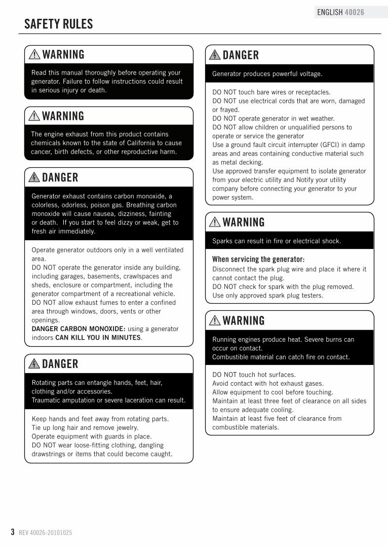
sAfETy RuLEs
The engine exhaust from this product contains chemicals known to the state of California to cause cancer, birth defects, or other reproductive harm .
Read this manual thoroughly before operating your generator . Failure to follow instructions could result in serious injury or death .
Generator exhaust contains carbon monoxide, a colorless, odorless, poison gas . Breathing carbon monoxide will cause nausea, dizziness, fainting or death . If you start to feel dizzy or weak, get to fresh air immediately .
Operate generator outdoors only in a well ventilated area .DO NOT operate the generator inside any building, including garages, basements, crawlspaces and sheds, enclosure or compartment, including the generator compartment of a recreational vehicle .DO NOT allow exhaust fumes to enter a confined area through windows, doors, vents or other openings .DANGER CARBON MONOXIDE: using a generator indoors CAN KILL YOU IN MINUTES .
Rotating parts can entangle hands, feet, hair, clothing and/or accessories . Traumatic amputation or severe laceration can result .
Keep hands and feet away from rotating parts .Tie up long hair and remove jewelry .Operate equipment with guards in place .DO NOT wear loose-fitting clothing, dangling drawstrings or items that could become caught .
Generator produces powerful voltage .
DO NOT touch bare wires or receptacles .DO NOT use electrical cords that are worn, damaged or frayed .DO NOT operate generator in wet weather .DO NOT allow children or unqualified persons to operate or service the generatorUse a ground fault circuit interrupter (GFCI) in damp areas and areas containing conductive material such as metal decking .Use approved transfer equipment to isolate generator from your electric utility and Notify your utility company before connecting your generator to your power system .
Sparks can result in fire or electrical shock .
When servicing the generator:Disconnect the spark plug wire and place it where it cannot contact the plug .DO NOT check for spark with the plug removed .Use only approved spark plug testers .
Running engines produce heat . Severe burns can occur on contact . Combustible material can catch fire on contact .
DO NOT touch hot surfaces .Avoid contact with hot exhaust gases .Allow equipment to cool before touching .Maintain at least three feet of clearance on all sides to ensure adequate cooling .Maintain at least five feet of clearance from combustible materials .
dANGER
dANGER
dANGER
WARNING
WARNING
WARNING
WARNING
REV 40026-20101025 4
40026 ENGLISH
sAfETy RuLEs
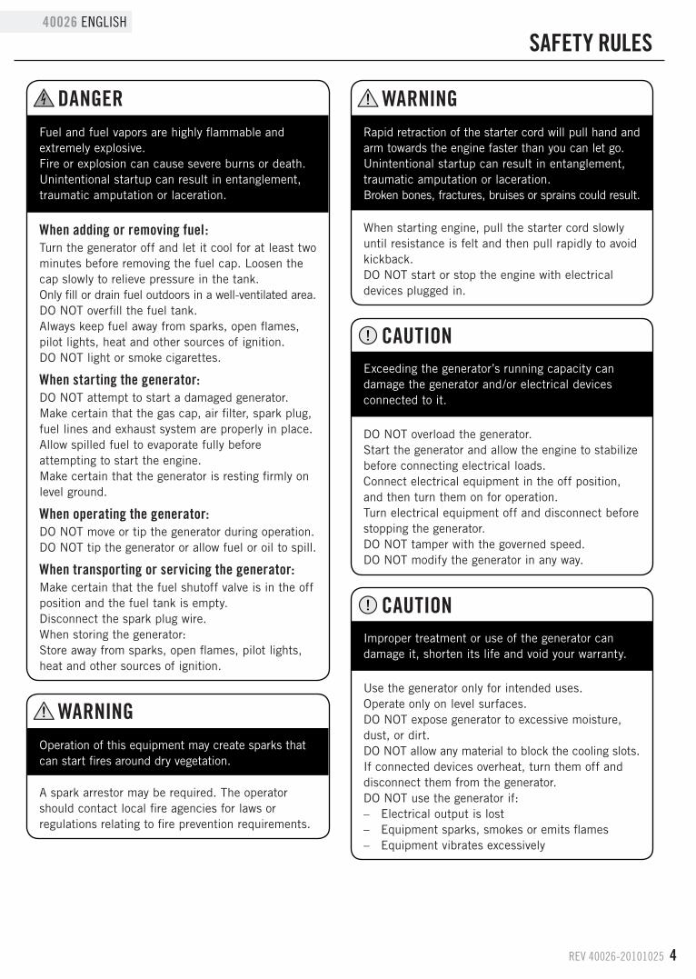
Fuel and fuel vapors are highly flammable and extremely explosive . Fire or explosion can cause severe burns or death . Unintentional startup can result in entanglement, traumatic amputation or laceration .
When adding or removing fuel:Turn the generator off and let it cool for at least two minutes before removing the fuel cap . Loosen the cap slowly to relieve pressure in the tank .Only fill or drain fuel outdoors in a well-ventilated area .DO NOT overfill the fuel tank .Always keep fuel away from sparks, open flames, pilot lights, heat and other sources of ignition .DO NOT light or smoke cigarettes .
When starting the generator:DO NOT attempt to start a damaged generator . Make certain that the gas cap, air filter, spark plug, fuel lines and exhaust system are properly in place .Allow spilled fuel to evaporate fully before attempting to start the engine .Make certain that the generator is resting firmly on level ground .
When operating the generator:DO NOT move or tip the generator during operation .DO NOT tip the generator or allow fuel or oil to spill .
When transporting or servicing the generator:Make certain that the fuel shutoff valve is in the off position and the fuel tank is empty .Disconnect the spark plug wire .When storing the generator:Store away from sparks, open flames, pilot lights, heat and other sources of ignition .
Rapid retraction of the starter cord will pull hand and arm towards the engine faster than you can let go . Unintentional startup can result in entanglement, traumatic amputation or laceration . Broken bones, fractures, bruises or sprains could result .
When starting engine, pull the starter cord slowly until resistance is felt and then pull rapidly to avoid kickback .DO NOT start or stop the engine with electrical devices plugged in .
Exceeding the generator’s running capacity can damage the generator and/or electrical devices connected to it .
DO NOT overload the generator .Start the generator and allow the engine to stabilize before connecting electrical loads .Connect electrical equipment in the off position, and then turn them on for operation .Turn electrical equipment off and disconnect before stopping the generator .DO NOT tamper with the governed speed . DO NOT modify the generator in any way .
Improper treatment or use of the generator can damage it, shorten its life and void your warranty .
Use the generator only for intended uses .Operate only on level surfaces .DO NOT expose generator to excessive moisture, dust, or dirt .DO NOT allow any material to block the cooling slots .If connected devices overheat, turn them off and disconnect them from the generator .DO NOT use the generator if: – Electrical output is lost – Equipment sparks, smokes or emits flames – Equipment vibrates excessively
Operation of this equipment may create sparks that can start fires around dry vegetation .
A spark arrestor may be required . The operator should contact local fire agencies for laws or regulations relating to fire prevention requirements .
CAuTION
WARNING
WARNINGdANGER
CAuTION
5 REV 40026-20101025
ENGLISH 40026
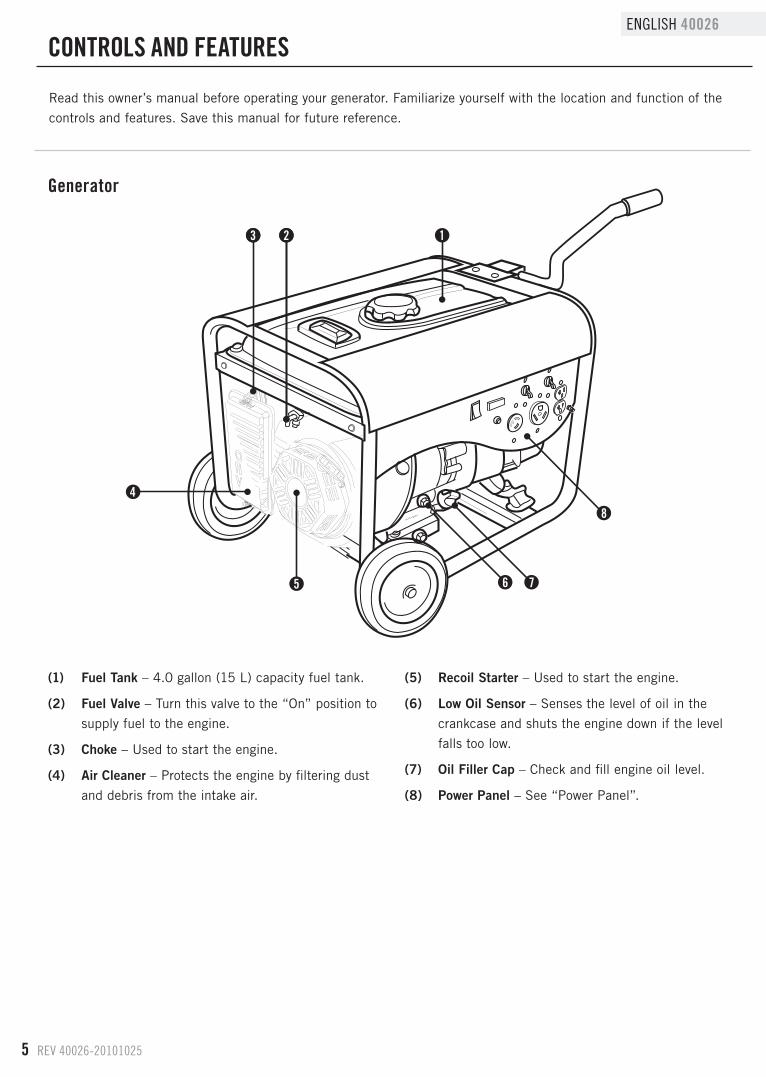
Read this owner’s manual before operating your generator . Familiarize yourself with the location and function of the
controls and features . Save this manual for future reference .
(1) Fuel Tank – 4 .0 gallon (15 L) capacity fuel tank .
(2) Fuel Valve – Turn this valve to the “On” position to
supply fuel to the engine .
(3) Choke – Used to start the engine .
(4) Air Cleaner – Protects the engine by filtering dust
and debris from the intake air .
(5) Recoil Starter – Used to start the engine .
(6) Low Oil Sensor – Senses the level of oil in the
crankcase and shuts the engine down if the level
falls too low .
(7) Oil Filler Cap – Check and fill engine oil level .
(8) Power Panel – See “Power Panel” .
Generator
CONTROLs ANd fEATuREs
1
5
4
6 7
8
2223
REV 40026-20101025 6
40026 ENGLISH
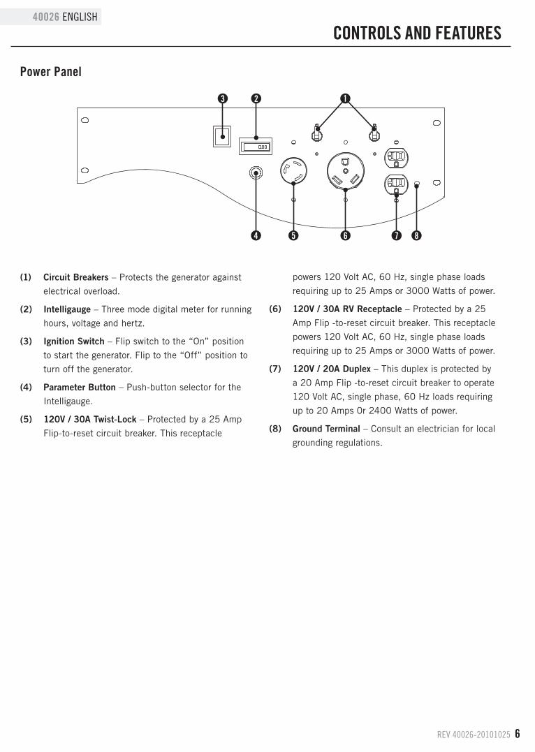
Power Panel
2
4 5
1
(1) Circuit Breakers – Protects the generator against
electrical overload .
(2) Intelligauge – Three mode digital meter for running
hours, voltage and hertz .
(3) Ignition Switch – Flip switch to the “On” position
to start the generator . Flip to the “Off” position to
turn off the generator .
(4) Parameter Button – Push-button selector for the
Intelligauge .
(5) 120V / 30A Twist-Lock – Protected by a 25 Amp
Flip-to-reset circuit breaker . This receptacle
powers 120 Volt AC, 60 Hz, single phase loads
requiring up to 25 Amps or 3000 Watts of power .
(6) 120V / 30A RV Receptacle – Protected by a 25
Amp Flip -to-reset circuit breaker . This receptacle
powers 120 Volt AC, 60 Hz, single phase loads
requiring up to 25 Amps or 3000 Watts of power .
(7) 120V / 20A Duplex – This duplex is protected by
a 20 Amp Flip -to-reset circuit breaker to operate
120 Volt AC, single phase, 60 Hz loads requiring
up to 20 Amps 0r 2400 Watts of power .
(8) Ground Terminal – Consult an electrician for local
grounding regulations .
CONTROLs ANd fEATuREs
3
6 7 8
7 REV 40026-20101025
ENGLISH 40026
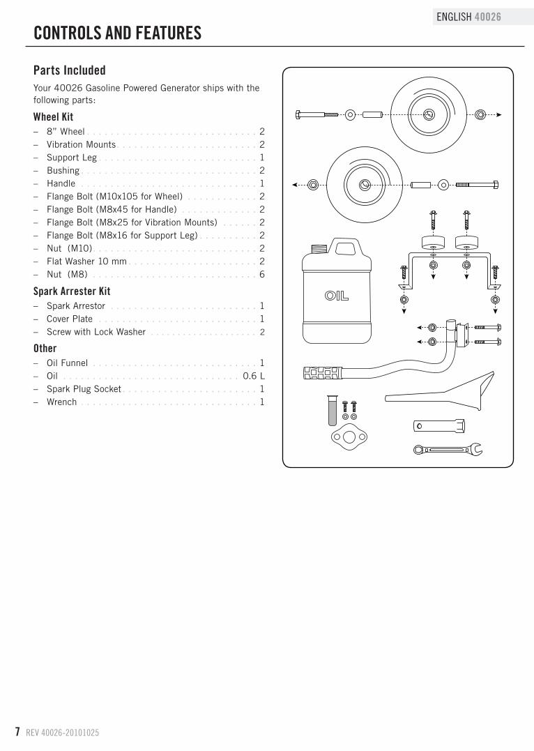
Parts IncludedYour 40026 Gasoline Powered Generator ships with the following parts:
Wheel Kit – 8” Wheel . . . . . . . . . . . . . . . . . . . . . . . . . . . . . 2 – Vibration Mounts . . . . . . . . . . . . . . . . . . . . . . . . 2 – Support Leg . . . . . . . . . . . . . . . . . . . . . . . . . . . 1 – Bushing . . . . . . . . . . . . . . . . . . . . . . . . . . . . . . 2 – Handle . . . . . . . . . . . . . . . . . . . . . . . . . . . . . . 1 – Flange Bolt (M10x105 for Wheel) . . . . . . . . . . . . 2 – Flange Bolt (M8x45 for Handle) . . . . . . . . . . . . . 2 – Flange Bolt (M8x25 for Vibration Mounts) . . . . . . 2 – Flange Bolt (M8x16 for Support Leg) . . . . . . . . . . 2 – Nut (M10) . . . . . . . . . . . . . . . . . . . . . . . . . . . . 2 – Flat Washer 10 mm . . . . . . . . . . . . . . . . . . . . . . 2 – Nut (M8) . . . . . . . . . . . . . . . . . . . . . . . . . . . . 6
spark Arrester Kit – Spark Arrestor . . . . . . . . . . . . . . . . . . . . . . . . . 1 – Cover Plate . . . . . . . . . . . . . . . . . . . . . . . . . . . 1 – Screw with Lock Washer . . . . . . . . . . . . . . . . . . . . 2
Other – Oil Funnel . . . . . . . . . . . . . . . . . . . . . . . . . . . . 1 – Oil . . . . . . . . . . . . . . . . . . . . . . . . . . . . . . 0 .6 L – Spark Plug Socket . . . . . . . . . . . . . . . . . . . . . . . 1 – Wrench . . . . . . . . . . . . . . . . . . . . . . . . . . . . . . 1
CONTROLs ANd fEATuREs
REV 40026-20101025 8
40026 ENGLISH
Your generator requires some assembly . This unit ships
from our factory without oil . It must be properly serviced
with fuel and oil before operation .
If you have any questions regarding the assembly of your
generator, call our help line at 1 (877) 338-0999 . Please
have your serial number and model number available .
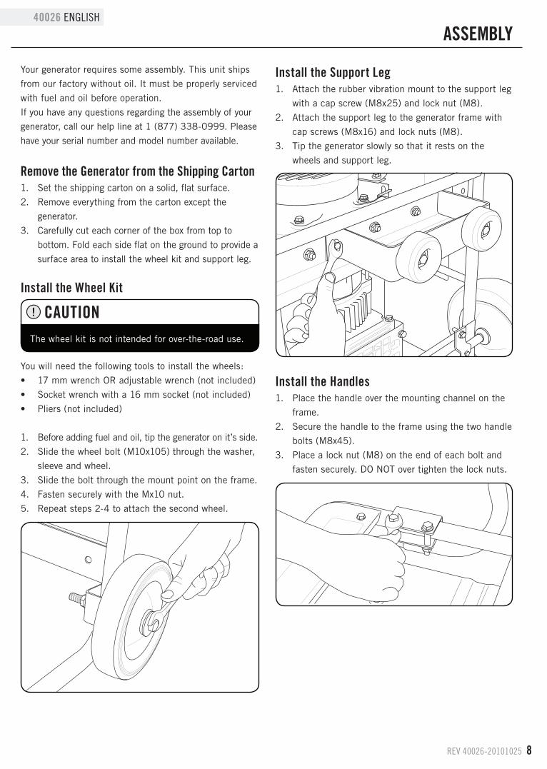
Remove the Generator from the shipping Carton1 . Set the shipping carton on a solid, flat surface .
2 . Remove everything from the carton except the
generator .
3 . Carefully cut each corner of the box from top to
bottom . Fold each side flat on the ground to provide a
surface area to install the wheel kit and support leg .
Install the Wheel Kit
You will need the following tools to install the wheels:
• 17 mm wrench OR adjustable wrench (not included)
• Socket wrench with a 16 mm socket (not included)
• Pliers (not included)
1 . Before adding fuel and oil, tip the generator on it’s side .
2 . Slide the wheel bolt (M10x105) through the washer,
sleeve and wheel .
3 . Slide the bolt through the mount point on the frame .
4 . Fasten securely with the Mx10 nut .
5 . Repeat steps 2-4 to attach the second wheel .
Install the support Leg1 . Attach the rubber vibration mount to the support leg
with a cap screw (M8x25) and lock nut (M8) .
2 . Attach the support leg to the generator frame with
cap screws (M8x16) and lock nuts (M8) .
3 . Tip the generator slowly so that it rests on the
wheels and support leg .
The wheel kit is not intended for over-the-road use .
CAuTION
Install the Handles1 . Place the handle over the mounting channel on the
frame .
2 . Secure the handle to the frame using the two handle
bolts (M8x45) .
3 . Place a lock nut (M8) on the end of each bolt and
fasten securely . DO NOT over tighten the lock nuts .
AssEMBLy
9 REV 40026-20101025
ENGLISH 40026
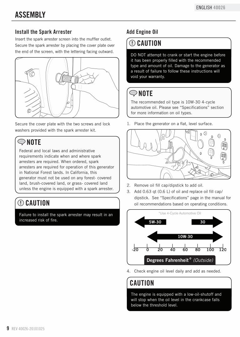
1 . Place the generator on a flat, level surface .
2 . Remove oil fill cap/dipstick to add oil .
3 . Add 0 .63 qt (0 .6 L) of oil and replace oil fill cap/
dipstick . See “Specifications” page in the manual for
oil recommendations based on operating conditions .
4 . Check engine oil level daily and add as needed .
The recommended oil type is 10W-30 4-cycle automotive oil . Please see “Specifications” section for more information on oil types .
NOTE
The engine is equipped with a low-oil-shutoff and will stop when the oil level in the crankcase falls below the threshold level .
CAuTION
Failure to install the spark arrester may result in an increased risk of fire .
CAuTION
Install the spark ArresterInsert the spark arrester screen into the muffler outlet .
Secure the spark arrester by placing the cover plate over
the end of the screen, with the lettering facing outward .
Secure the cover plate with the two screws and lock
washers provided with the spark arrester kit .
Federal and local laws and administrative requirements indicate when and where spark arresters are required . When ordered, spark arresters are required for operation of this generator in National Forest lands . In California, this generator must not be used on any forest- covered land, brush-covered land, or grass- covered land unless the engine is equipped with a spark arrester .
NOTE
Add Engine Oil
DO NOT attempt to crank or start the engine before it has been properly filled with the recommended type and amount of oil . Damage to the generator as a result of failure to follow these instructions will void your warranty .
CAuTION
AssEMBLy
REV 40026-20101025 10
40026 ENGLISH
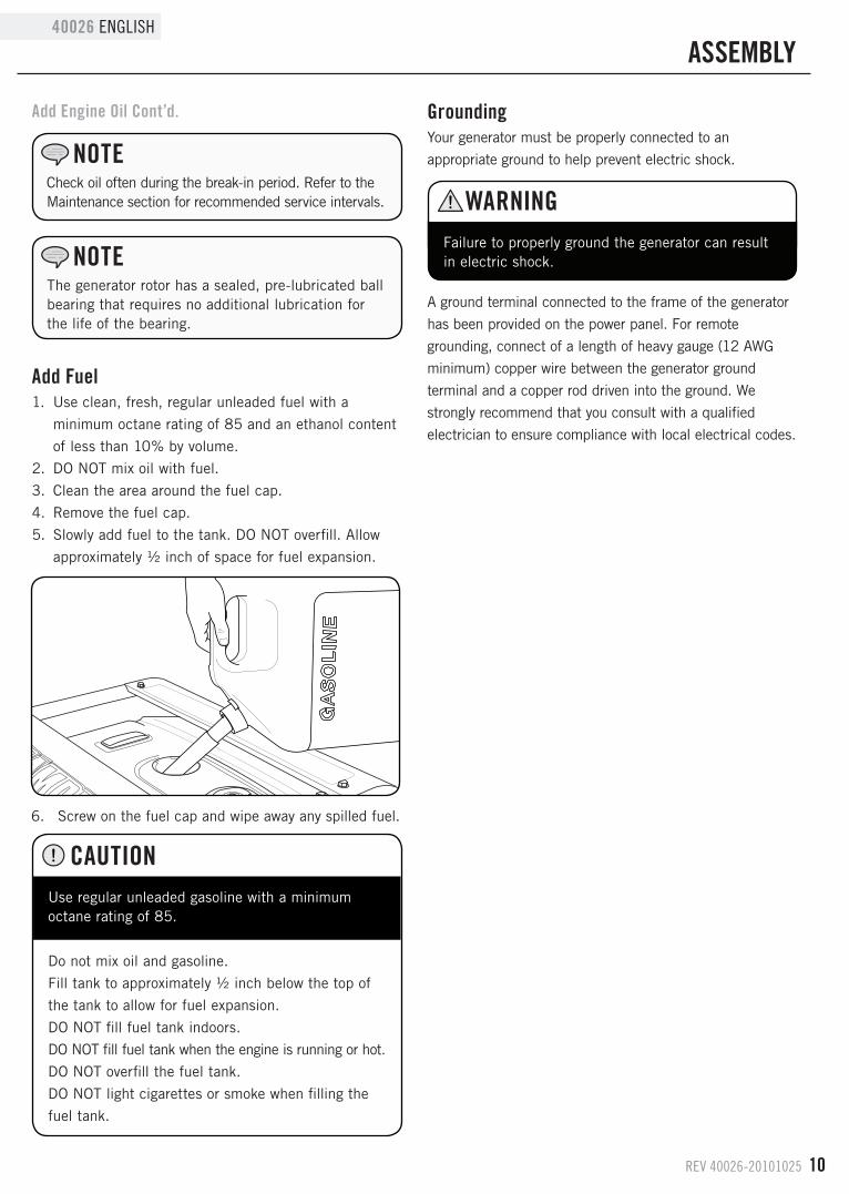
Add fuel1 . Use clean, fresh, regular unleaded fuel with a
minimum octane rating of 85 and an ethanol content
of less than 10% by volume .
2 . DO NOT mix oil with fuel .
3 . Clean the area around the fuel cap .
4 . Remove the fuel cap .
5 . Slowly add fuel to the tank . DO NOT overfill . Allow
approximately ½ inch of space for fuel expansion .
GroundingYour generator must be properly connected to an
appropriate ground to help prevent electric shock .
A ground terminal connected to the frame of the generator
has been provided on the power panel . For remote
grounding, connect of a length of heavy gauge (12 AWG
minimum) copper wire between the generator ground
terminal and a copper rod driven into the ground . We
strongly recommend that you consult with a qualified
electrician to ensure compliance with local electrical codes .
6 . Screw on the fuel cap and wipe away any spilled fuel .
Failure to properly ground the generator can result in electric shock .
Check oil often during the break-in period . Refer to the Maintenance section for recommended service intervals .
NOTE
The generator rotor has a sealed, pre-lubricated ball bearing that requires no additional lubrication for the life of the bearing .
NOTE
WARNING
Use regular unleaded gasoline with a minimum octane rating of 85 .
Do not mix oil and gasoline .
Fill tank to approximately ½ inch below the top of
the tank to allow for fuel expansion .
DO NOT fill fuel tank indoors .
DO NOT fill fuel tank when the engine is running or hot .
DO NOT overfill the fuel tank .
DO NOT light cigarettes or smoke when filling the
fuel tank .
CAuTION
Add Engine Oil Cont’d.
AssEMBLy
11 REV 40026-20101025
ENGLISH 40026
Generator LocationPlease consult your local authority . In some areas,
generators must be registered with the local utility .
Generators used at construction sites may be subject to
additional rules and regulations .
This generator must have at least five feet of clearance
from combustible material . Leave at least three feet
of clearance on all sides of the generator to allow for
adequate cooling, maintenance and servicing .
Place the generator in a well-ventilated area . DO NOT
place the generator near vents or intakes where exhaust
fumes could be drawn into occupied or confined
spaces . Carefully consider wind and air currents when
positioning generator .
GroundingThe generator system ground connects the frame to the
ground terminals on the power panel .
surge Protection
Electronic devices, including computers and many
programmable appliances use components that are
designed to operate within a narrow voltage range and
may be affected by momentary voltage fluctuations .
While there is no way to prevent voltage fluctuations, you
can take steps to protect sensitive electronic equipment .
1. Install UL1449, CSA-listed, plug-in surge suppressors
on the outlets feeding your sensitive equipment.
Surge suppressors come in single- or multi-outlet
styles . They’re designed to protect against virtually
all short-duration voltage fluctuations .
2. Obtain an Uninterruptible Power Supply (UPS) device.
Most UPS devices come with a rechargeable battery
between the electronic equipment and power supply
source . The device buffers the voltage and protects
against virtually all short-duration voltage fluctuations .
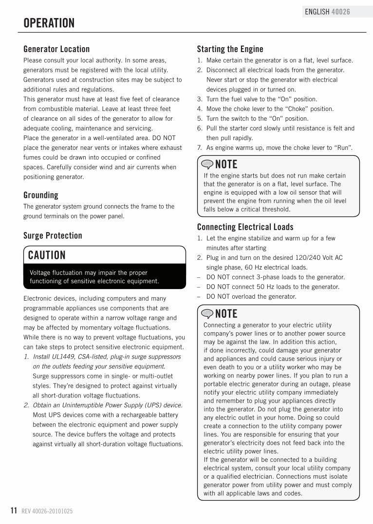
Voltage fluctuation may impair the proper functioning of sensitive electronic equipment .
starting the Engine1 . Make certain the generator is on a flat, level surface .
2 . Disconnect all electrical loads from the generator .
Never start or stop the generator with electrical
devices plugged in or turned on .
3 . Turn the fuel valve to the “On” position .
4 . Move the choke lever to the “Choke” position .
5 . Turn the switch to the “On” position .
6 . Pull the starter cord slowly until resistance is felt and
then pull rapidly .
7 . As engine warms up, move the choke lever to “Run” .
If the engine starts but does not run make certain that the generator is on a flat, level surface . The engine is equipped with a low oil sensor that will prevent the engine from running when the oil level falls below a critical threshold .
NOTE
CAuTION
OPERATION
Connecting Electrical Loads1 . Let the engine stabilize and warm up for a few
minutes after starting
2 . Plug in and turn on the desired 120/240 Volt AC
single phase, 60 Hz electrical loads .
– DO NOT connect 3-phase loads to the generator .
– DO NOT connect 50 Hz loads to the generator .
– DO NOT overload the generator .
Connecting a generator to your electric utility company’s power lines or to another power source may be against the law . In addition this action, if done incorrectly, could damage your generator and appliances and could cause serious injury or even death to you or a utility worker who may be working on nearby power lines . If you plan to run a portable electric generator during an outage, please notify your electric utility company immediately and remember to plug your appliances directly into the generator . Do not plug the generator into any electric outlet in your home . Doing so could create a connection to the utility company power lines . You are responsible for ensuring that your generator’s electricity does not feed back into the electric utility power lines .If the generator will be connected to a building electrical system, consult your local utility company or a qualified electrician . Connections must isolate generator power from utility power and must comply with all applicable laws and codes .
NOTE
REV 40026-20101025 12
40026 ENGLISH
stopping the Engine1 . Turn off and unplug all electrical loads . Never start or
stop the generator with electrical devices plugged in
or turned on .
2 . Let the generator run at no-load for several minutes
to stabilize internal temperatures of the engine and
generator .
3 . Turn the ignition switch to the “Off” position .
4 . Turn the fuel valve to the “Off” position .
OPERATION
do Not Overload GeneratorCapacityFollow these simple steps to calculate the running and
starting watts necessary for your purposes .
1 . Select the electrical devices you plan on running at
the same time .
2 . Total the running watts of these items . This is
the amount of power you need to keep your items
running .
3 . Identify the highest starting wattage of all devices
identified in step 1 . Add this number to the number
calculated in step 2 . Surge wattage is the extra
burst of power needed to start some electric driven
equipment . Following the steps listed under “Power
Management” will guarantee that only one device will
be starting at a time .
Power ManagementUse the following formula to convert voltage and
amperage to watts:
Volts x Amps = Watts
To prolong the life of your generator and attached
devices, follow these steps to add electrical load:
1 . Start the generator with no electrical load attached
2 . Allow the engine to run for several minutes to stabilize .
3 . Plug in and turn on the first item . It is best to attach
the item with the largest load first .
4 . Allow the engine to stabilize .
5 . Plug in and turn on the next item .
6 . Allow the engine to stabilize .
7 . Repeat steps 5-6 for each additional item .
Never exceed the specified capacity when adding loads to the generator .
NOTE
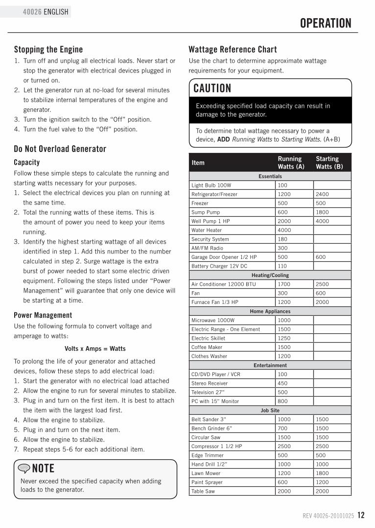
Wattage Reference ChartUse the chart to determine approximate wattage
requirements for your equipment .
Item Running Watts (A)
Starting Watts (B)
Essentials
Light Bulb 100W 100
Refrigerator/Freezer 1200 2400
Freezer 500 500
Sump Pump 600 1800
Well Pump 1 HP 2000 4000
Water Heater 4000
Security System 180
AM/FM Radio 300
Garage Door Opener 1/2 HP 500 600
Battery Charger 12V DC 110
Heating/Cooling
Air Conditioner 12000 BTU 1700 2500
Fan 300 600
Furnace Fan 1/3 HP 1200 2000
Home Appliances
Microwave 1000W 1000
Electric Range - One Element 1500
Electric Skillet 1250
Coffee Maker 1500
Clothes Washer 1200
Entertainment
CD/DVD Player / VCR 100
Stereo Receiver 450
Television 27” 500
PC with 15” Monitor 800
Job Site
Belt Sander 3” 1000 1500
Bench Grinder 6” 700 1500
Circular Saw 1500 1500
Compressor 1 1/2 HP 2500 2500
Edge Trimmer 500 500
Hand Drill 1/2” 1000 1000
Lawn Mower 1200 1800
Paint Sprayer 600 1200
Table Saw 2000 2000
Exceeding specified load capacity can result in damage to the generator .
To determine total wattage necessary to power a device, ADD Running Watts to Starting Watts. (A+B)
CAuTION
13 REV 40026-20101025
ENGLISH 40026
The owner/operator is responsible for all periodic
maintenance .
Complete all scheduled maintenance in a timely manner .
Correct any issue before operating the generator .
Never operate a damaged or defective generator .
Tampering with the factory set governor will void your warranty .
Engine MaintenanceTo prevent accidental starting, remove and ground spark
plug wire before performing any service .
OilChange oil when the engine is warm . Refer to the oil specifi cation to select the proper grade of oil for your operating environment .1 . Remove the oil drain plug with a 15 mm socket and
extension .2 . Allow the oil to drain completely .3 . Replace the drain plug .4 . Remove oil fi ll cap/dipstick to add oil .5 . Add 0 .63 qt (0 .6 L) of oil and replace oil fi ll
cap/dipstick .6 . Dispose of used oil at an approved waste
management facility .
Air filter1 . Remove the snap-on cover holding the air fi lter to
the assembly .
2 . Remove the foam element .
3 . Wash in liquid detergent and water . Squeeze
thoroughly dry in a clean cloth .
4 . Saturate in clean engine oil .
5 . Squeeze in a clean, absorbent cloth to remove all
excess oil .
6 . Place the fi lter in the assembly .
7 . Reattach the air fi lter cover and snap in place .
spark Plugs1 . Remove the spark plug cable from the spark plug .
2 . Use the spark plug tool that shipped with your
generator to remove the plug .
3 . Inspect the electrode on the plug . It must be clean and
not worn to produce the spark required for ignition .
4 . Make certain the spark plug gap is 0 .7 – 0 .8 mm or
(0 .028 – 0 .031 in .) .
5 . Refer to the spark plug recommendation chart when
replacing the plug .
6 . Carefully thread the plug into the engine .
7 . Use the spark plug tool to fi rmly install the plug .
8 . Attach the spark plug wire to the plug .
For service or parts assistance, contact our help line at 1 (877) 338-0999
NOTE
Maintenance, replacement, or repair of emission control devices and systems may be performed by any non-road engine repair establishment or individual .
NOTE
WARNING
WARNING
Improper maintenance will void your warranty .
WARNING
Oil Cont’d.
0.7 - 0.8 mm0.028 - 0.031 in.
MAINTENANCE ANd sTORAGE
REV 40026-20101025 14
40026 ENGLISH
AdjustmentsThe air-fuel mixture is not adjustable . Tampering with
the governor can damage your generator and your
electrical devices and will void your warranty . CPE
recommends that you contact our service line at
1 (877) 338-0999 for all other service and/or
adjustment needs .
Maintenance scheduleFollow the service intervals indicated in the following
maintenance schedule .
Service your generator more frequently when operating
in adverse conditions .
Contact our help line at 1 (877) 338-0999 to locate the
nearest Champion Power Equipment certified service
dealer for your generator or engine maintenance needs .
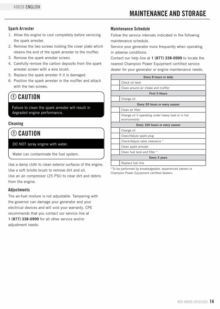
*To be performed by knowledgeable, experienced owners or Champion Power Equipment certified dealers .
Use a damp cloth to clean exterior surfaces of the engine .
Use a soft bristle brush to remove dirt and oil .
Use an air compressor (25 PSI) to clear dirt and debris
from the engine .
Every 8 hours or daily
Check oil level
Clean around air intake and muffler
First 5 Hours
Change oil
Every 50 hours or every season
Clean air filter
Change oil if operating under heavy load or in hot environments
Every 100 hours or every season
Change oil
Clean/Adjust spark plug
Check/Adjust valve clearance *
Clean spark arrester
Clean fuel tank and filter *
Every 3 years
Replace fuel line
Cleaning
DO NOT spray engine with water .
CAuTION
Water can contaminate the fuel system .
spark Arrester1 . Allow the engine to cool completely before servicing
the spark arrester .
2 . Remove the two screws holding the cover plate which
retains the end of the spark arrester to the muffler .
3 . Remove the spark arrester screen .
4 . Carefully remove the carbon deposits from the spark
arrester screen with a wire brush .
5 . Replace the spark arrester if it is damaged .
6 . Position the spark arrester in the muffler and attach
with the two screws .
Failure to clean the spark arrester will result in degraded engine performance .
CAuTION
MAINTENANCE ANd sTORAGE
15 REV 40026-20101025
ENGLISH 40026
Generator MaintenanceMake certain that the generator is kept clean and stored
properly . Only operate the unit on a flat, level surface in
a clean, dry operating environment . DO NOT expose the
unit to extreme conditions, excessive dust, dirt, moisture
or corrosive vapors .
storageThe generator should be started at least once every 14
days and allowed to run for at least 20 minutes . For
longer term storage, please follow these guidelines .
Generator storage1 . Allow the engine to cool completely before storage .
2 . Clean the generator according to the instructions in
the Maintenance section .
3 . Turn off the fuel supply at the Fuel Valve .
4 . Drain all fuel completely from the fuel line and
carburetor to prevent gum from forming .
5 . Add a fuel stabilizer into the fuel tank .
6 . Change the oil .
7 . Remove the spark plug and pour about ½ ounce
of oil into the cylinder . Crank the engine slowly to
distribute the oil and lubricate the cylinder .
8 . Reattach the spark plug .
9 . Store the unit in a clean, dry place out of direct
sunlight .
Use a damp cloth to clean exterior surfaces of the generator .
Use a soft bristle brush to remove dirt and oil .
Use an air compressor (25 PSI) to clear dirt and debris
from the generator .
Inspect all air vents and cooling slots to ensure that they
are clean and unobstructed .
DO NOT use a garden hose to clean the generator .
Water can enter the generator through the cooling slots and damage the generator windings .
MAINTENANCE ANd sTORAGE
CAuTION
REV 40026-20101025 16
40026 ENGLISH
Engine specifications – Engine . . . . . . . . . . . . . . . . . . . . 196 cc OHV CPE
valve Clearance – Intake: 0 .13-0 .17 mm (0 .005 – 0 .007 in .)
– Exhaust: 0 .18-0 .22 mm (0 .007 – 0 .009 in .)
OilUse 4-Cycle automotive oil .
Oil capacity is 0 .63 qt qt (0 .6 L) .
Please reference the following chart for recommended
oil types for use in the generator .
fuelFuel capacity is 4 gallons (15 L) . Use regular unleaded
gasoline with a minimum octane rating of 85 and an
ethanol content of less than 10% by volume .
Generator specifications – Running Wattage . . . . . . . . . . . . . . . . . 3000 Watts
– Starting Wattage . . . . . . . . . . . . . . . . . 3500 Watts
– AC Voltage . . . . . . . . . . . . . . . . . . . . . . . . . 120 V
– Phase . . . . . . . . . . . . . . . . . . . . . . . . . . . . Single
– Frequency . . . . . . . . . . . . . . . . . . . . . . . . . 60 Hz
– Fuel Capacity . . . . . . . . . . . . . . . . 4 gallons (15 L)
– Weight . . . . . . . . . . . . . . . . . 113 .54 lbs . (51 .5 kg)
– Height . . . . . . . . . . . . . . . . . . . 20 .3 in . (51 .5 cm)
– Width . . . . . . . . . . . . . . . . . . 23 .97 in . (60 .9 cm)
– Length . . . . . . . . . . . . . . . . . . . . 30 .3 in . (77 cm)
spark PlugsRecommended replacement spark plug:
– NGK BR6ES or equivalentMake certain the spark plug gap is 0 .7 - 0 .8 mm or
(0 .028 - 0 .031 in .) .
sPECIfICATIONs
17 REV 40026-20101025
ENGLISH 40026
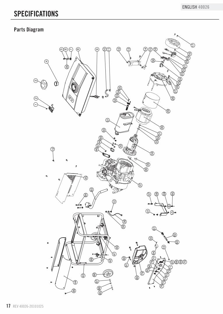
Parts diagram
sPECIfICATIONs
REV 40026-20101025 18
40026 ENGLISH Parts List
# Part Number Description Qty1 GB819-2000-S5-6 Screw M5x10 2
2 ST168FD-1160100 Fuel Meter Assembly 1
3 ST168FD-1160200 Fuel Tank Cap 1
4 ST168F-1160500 Fuel Filter 1
5 GB5789-86-FB6-20 Flange Bolt M6x20 4
6 ST02FD-04100014 Washer 6 .5 mm 4
7 ST168FD-1163000 Tank Rubber 4
8 ST02FD-04010000 Fuel Tank 1
9 ST168FD-1160400 Fuel Valve 1
10 ST168FD-1160002A Fuel Line 1
11 ST188FD-1070006A Clip 2
12 GB5789-86-FB6-12 Flange Bolt M6x12 11
13 GB5789-86-FB8-20 Flange Bolt M8x20 3
14 ST02FD-1150100 Muffler Stay (II) 1
15 ST168FD-1100002B Muffler Stay (I) 1
16 ST168FD-1150230 Terminal 1
17 GB5789-86-FB5-12 Flange Bolt M5x12 3
18 ST02FD-1152002-2 Generator End Cover 1
19 GB5789-86-FB5-16 Flange Bolt M5x16 2
20 ST168FD-1152031 AVR 1
21 GB5781-86-B5-16 Bolt M5x16 3
22 GB93-87-SW5 Lock Washer 5 3
23 GB90-85-W5 Washer 5 mm 3
24 ST02FD-1152035 Brush Assembly 1
25 GB5789-86-FB6-158 Flange Bolt M6x158 4
26 GB93-87-SW6 Lock Washer 6 mm 8
27 GB90-85-W6 Washer 6 mm 4
28 ST02FD-1152032 End Cover 1
29 ST02FD-1152001 Stator Cover 1
30 ST02FD-1152020-cpe Stator Assembly 1
31 GB5789-86-FB8-233 Flange Bolt M8x233 1
32 GB93-87-SW8 Lock Washer 8 mm 3
33 GB90-85-W8 Washer 8 mm 1
34 ST02FD-1152010 Rotor Comp 1
35 ST02FD-02100012 Build Up (A) 1
36 ST02FD-02100011 Build Up (B) 1
37 ST168FD-II-01000000-G Engine 1
38 ST02FD-1151207-M Ground 1
39 GB6177-86-N6 Nut M6 1
40 ST02FD-1151300B Bottom Rubber (I) 2
41 GB6177-86-N8 Nut M8 14
42 ST02FD-1151300A Bottom Rubber (II) 2
43 ST02FD-03631000 Frame 1
44 ST168FD-1151301 Frame Wing 2
45 ST02FD-1151002 Muffler Cover 1
46 ST168FD-1090006 Air Cleaner Stay 1
# Part Number Description Qty47 GB5789-86-FB6-8 Flange Bolt M6x8 1
48 ST168F-1100200-G Muffler Gasket 1
49 GB97 .1-85-W8 Washer 8 mm 2
50 GB6170-86-N8 Nut M8 2
51 ST168FD-1100000-G Muffler 1
52 ST188FD-1180121 Spark Arrester Assembly
1
53 ST188FD-1100010-88 Spark Arrester Cover 1
54 GB93-87-SW5 Lock Washer 5 mm 2
55 GB5789-86-FB5-15 Flange Bolt M5x15 3
56 ST02FD-1151036 Plate Pinch 1
57 GB5789-86-FB8-16 Flange Bolt M8x16 2
58 ST05FD-03020301-60 Support leg (2 .36) 1
59 ST188FD-1743002-C Vibration Mount 2
60 GB5789-86-FB8-32 Flange Bolt M8x25 2
61 ST05FD-1170003-B Build Up 1
62 ST05FD-1151209-1 Conduit 1
63 ST02FD-1151201 Build Up 1
64 OV01-00000000-1 Transition 1
65 2630-120 Intelliguage 1
66 GB818-85-S4-14 Screw M4x14 6
67 GB5781-86-B6-22 Bolt M6x22 1
68 GB97 .1-85-W6 Washer 6 mm 2
69 GB859-86-SW6 Lock Washer 6 mm 2
70 GB41-86-N6 Nut M6 2
71 ST02FD-1151200C Receptacle 5-20R 1
72 1010 Receptacle RV 1
73 0220 L5-30R Receptacle 1
74 2631 Touch Switch 1
75 ST02FD-1151205A Engine switch 1
76 ST02FD-05031900 Control Panel 1
77 ST05FD-1151202-20 AC .20A CIRCUIT BREAKERS
1
78 ST05FD-1151202-25 AC .25A CIRCUIT BREAKERS
1
79 ST168FD-1151201-R Control Box 1
80 ST188FD-1020001 Grommet 1
81 GB97 .1-85-W5 Washer 5 mm 3
82 GB818-85-S5-38 Screw M5x38 3
83 ST02FD-1151400 Handle 1
84 GB5789-86-FB8-45 Flange Bolt M8x45 2
85 GB5780-2000-B10-105 Bolt M10x105 2
86 GB96-85-P10 Flat Washer 10 mm 2
87 ST02FD-03621001 Bush10 .5x58 .5 2
88 ST177FD-1152300 8 in Wheel 2
89 GB/T6182-2000-N10 Nut M10 2
90 GB5789-86-FB6-12 Flange Bolt M6x12 8
19 REV 40026-20101025
ENGLISH 40026
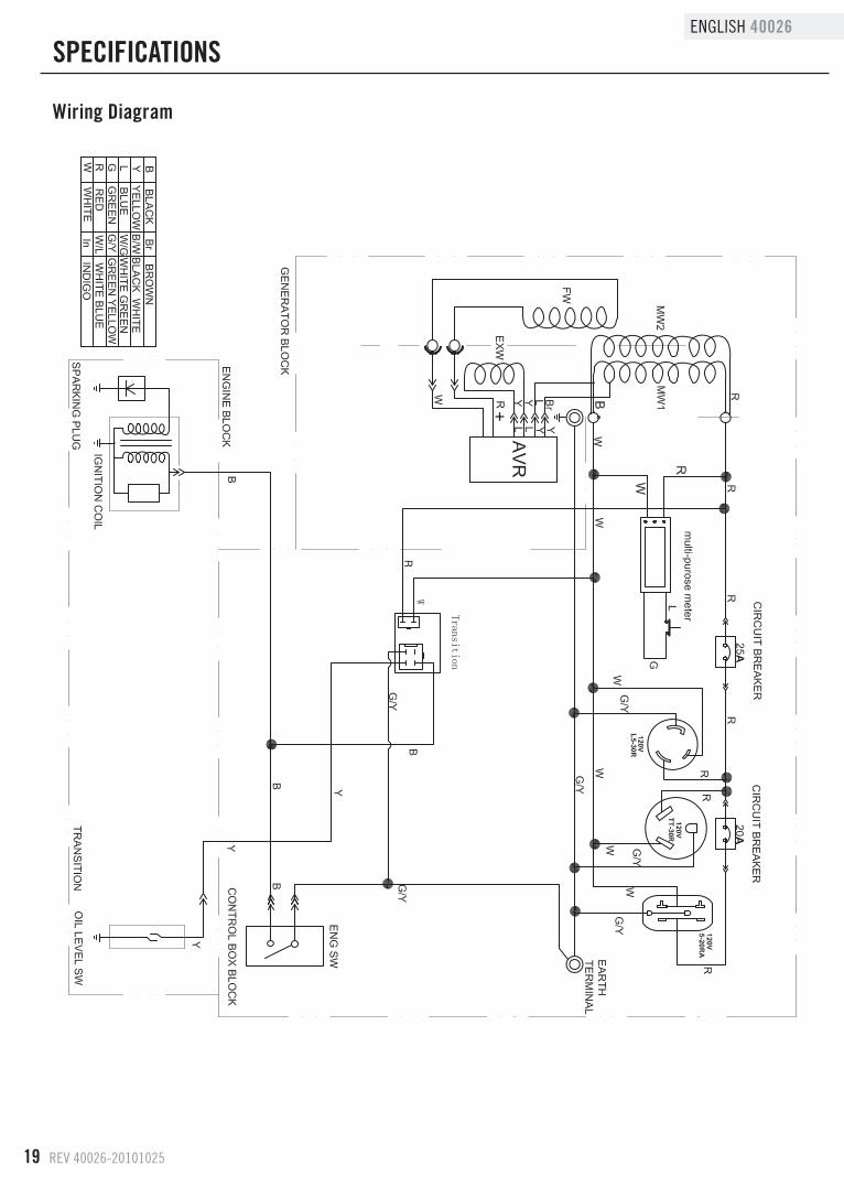
Wiring diagram
sPECIfICATIONs
REV 40026-20101025 20
40026 ENGLISH
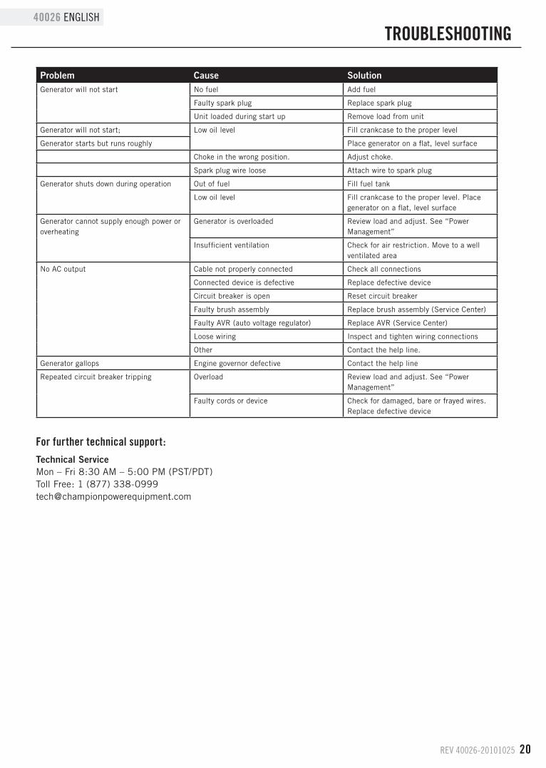
TROuBLEsHOOTING
Problem Cause SolutionGenerator will not start No fuel Add fuel
Faulty spark plug Replace spark plug
Unit loaded during start up Remove load from unit
Generator will not start; Low oil level Fill crankcase to the proper level
Generator starts but runs roughly Place generator on a flat, level surface
Choke in the wrong position . Adjust choke .
Spark plug wire loose Attach wire to spark plug
Generator shuts down during operation Out of fuel Fill fuel tank
Low oil level Fill crankcase to the proper level . Place generator on a flat, level surface
Generator cannot supply enough power or overheating
Generator is overloaded Review load and adjust . See “Power Management”
Insufficient ventilation Check for air restriction . Move to a well ventilated area
No AC output Cable not properly connected Check all connections
Connected device is defective Replace defective device
Circuit breaker is open Reset circuit breaker
Faulty brush assembly Replace brush assembly (Service Center)
Faulty AVR (auto voltage regulator) Replace AVR (Service Center)
Loose wiring Inspect and tighten wiring connections
Other Contact the help line .
Generator gallops Engine governor defective Contact the help line
Repeated circuit breaker tripping Overload Review load and adjust . See “Power Management”
Faulty cords or device Check for damaged, bare or frayed wires . Replace defective device
for further technical support:
Technical ServiceMon – Fri 8:30 AM – 5:00 PM (PST/PDT)Toll Free: 1 (877) 338-0999tech@championpowerequipment .com
21 REV 40026-20101025
ENGLISH 40026
WARRANTyCHAMPION POWER EQUIPMENT
2 YEAR LIMITED WARRANTY
Warranty QualificationsChampion Power Equipment (CPE) will register this warranty upon receipt of your Warranty Registration Card and a copy of your sales receipt from one of CPE’s retail locations as proof of purchase .Please submit your warranty registration and your proof of purchase within ten (10) days of the date of purchase .
Repair/Replacement WarrantyCPE warrants to the original purchaser that the mechanical and electrical components will be free of defects in material and workmanship for a period of one year (parts and labor) and two years (parts) from the original date of purchase (90 days (parts and labor) and 180 days (parts) for commercial & industrial use) . Transportation charges on product submitted for repair or replacement under this warranty are the sole responsibility of the purchaser . This warranty only applies to the original purchaser and is not transferable .
do Not Return The unit To The Place Of PurchaseContact CPE’s Technical Service and CPE will troubleshoot any issue via phone or e-mail . If the problem is not corrected by this method, CPE will, at its option, authorize evaluation, repair or replacement of the defective part or component at a CPE Service Center . CPE will provide you with a case number for warranty service . Please keep it for future reference . Repairs or replacements without prior authorization, or at an unauthorized repair facility, will not be covered by this warranty .
Warranty ExclusionsThis warranty does not cover the following repairs and equipment:
Normal WearGenerators need periodic parts and service to perform well . This warranty does not cover repair when normal use has exhausted the life of a part or the equipment as a whole .
Installation, use and MaintenanceThis warranty will not apply to parts and/or labor if this generator is deemed to have been misused, neglected, involved in an accident, abused, loaded beyond the generator’s limits, modified, installed improperly or connected incorrectly to any electrical component .
Installation, use and Maintenance Cont’d. Normal maintenance such as spark plugs, air filters, adjustments, fuel system cleaning and obstruction due to buildup is not covered by this warranty .
Other ExclusionsThis warranty excludes: – Cosmetic defects such as paint, decals, etc . – Wear items such as filter elements, o-rings, etc . – Accessory parts such as starting batteries, and
storage covers . – Failures to due acts of God and other force majeure
events beyond the manufacturer’s control . – Problems caused by parts that are not original
Champion Power Equipment parts .This warranty does not apply to generators used for prime power in place of a utility .
Limits of Implied Warranty and Consequential damageChampion Power Equipment disclaims any obligation to cover any loss of time, use of this product, freight, or any incidental or consequential claim by anyone from using this generator . THIS WARRANTY IS IN LIEU OF ALL OTHER WARRANTIES, EXPRESS OR IMPLIED, INCLUDING WARRANTIES OF MERCHANTABILITY OR FITNESS FOR A PARTICULAR PURPOSE . A unit provided as an exchange will be subject to the warranty of the original unit . The length of the warranty governing the exchanged unit will remain calculated by reference to the purchase date of the original unit .This warranty gives you certain legal rights which may change from state to state . Your state may also have other rights you may be entitled to that are not listed within this warranty .
Contact InformationAddressChampion Power Equipment, Inc .Customer Service10006 Santa Fe Springs Rd .Santa Fe Springs, CA 90670www .championpowerequipment .com
Customer serviceMon – Fri 8:30 AM – 5:00 PM (PST/PDT)Toll Free:1 (877) 338-0999Fax no .: 1 (562) 236-9429
Technical serviceMon – Fri 8:30 AM – 5:00 PM (PST/PDT)Toll Free: 1 (877) 338-0999tech@championpowerequipment .com
WARRANTy
REV 40026-20101025 22
40026 ENGLISH
WARRANTy
Champion Power Equipment, Inc (CPE), and the united states Environment Protection Agency (u.s. EPA.)
Emission Control system WarrantyYour Champion Power Equipment (CPE) engine complies with U .S . EPA emission regulations .
yOuR WARRANTy RIGHTs ANd OBLIGATIONs:The US EPA AND CPE are pleased to explain the Federal Emission Control Systems Warranty on your 1997 and later small off-road engine . New engines must be designed, built and equipped, at the time of sale, to meet U .S . EPA regulations for small non-road engines . CPE must warrant the emission control system on your small off-road engine for the period of time listed below, provided there has been no abuse, neglect, unapproved modification, or improper maintenance of your small off-road engine .
Your emission control system may include parts such as the carburetor, fuel-injection system, the ignition system, catalytic converter and fuel lines . Also included may be hoses, belts, connectors and other emission related assemblies . Where a warrantable condition exits, CPE will repair your small off-road engine at no cost to you including diagnosis, parts and labor .
MANufACTuRER’s EMIssION CONTROL sysTEM WARRANTy COvERAGE:This emission control system is warranted for two years, subject to provisions set forth below . If, during the warranty period, emission related part on your engine is defective in materials or workmanship, the part will be repaired or replaced by CPE .
OWNER WARRANTy REsPONsIBILITIEs:As the small off-road engine owner, you are responsible for the performance of the required maintenance listed in your Owner’s Manual . CPE recommends that you retain all your receipts covering maintenance on your small off-road engine, but CPE cannot deny warranty solely for the lack of receipts or for your failure to ensure the performance of all scheduled maintenance .
As the small off-road engine owner, you should however be aware that CPE may deny you warranty coverage if your small, off-road engine or a part has failed due to abuse, neglect, improper maintenance or unapproved modifications.
You are responsible for presenting your small off-road engine to an Authorized CPE service outlet, CPE dealer or CPE, Santa Fe Springs, Ca . as soon as a problem exists . The warranty repairs should be completed in a reasonable amount of time, not to exceed 30 days .
If you have any questions regarding your warranty rights and responsibilities, you should contact:
Champion Power Equipment, Inc.ATTN: Customer Service
10006 Santa Fe Springs RoadSanta Fe Springs, CA 90670
Tel: 1-877-338-0999
The emission warranty is a defects warranty . Defects are judged on normal engine performance . The warranty is not related to an in-use emission test .
23 REV 40026-20101025
ENGLISH 40026
WARRANTy
EMIssION CONTROL sysTEM WARRANTyThe following are specific provisions relative to your Emission Control System Warranty Coverage.
Emission Control System Warranty (ECS Warranty) for 1997 and later model year engines):
1. APPLICABILITY: This warranty shall apply to 1997 and later model year engines) . The ECS Warranty Period shall begin on the date the new engine or equipment is delivered to its original, end-use purchaser, and shall continue
for 24 consecutive months thereafter .
2. GENERAL EMISSIONS WARRANTY COVERAGE CPE warrants to the original, end-use purchaser of the new engine or equipment and to each subsequent
purchaser that each of its small off-road engines is:
a . Designed, built and equipped so as to conform at the time of sale with applicable regulations under section
213 of the Clean Air Ac, as amended, 42 U .S .C . 7401 et seq .
b . Free from defects in materials and workmanship that cause the failure of a warranted part to be identical in all
material respects to the part as described in the engine manufacturer’s application for certification for a period
of two years .
3. THE WARRANTY ON EMISSION-RELATED PARTS WILL BE INTERPRETED AS FOLLOWS:a . Any warranted part that is not scheduled for replacement as required maintenance in the Owners Manual shall
be warranted for the ECS Warranty Period . If any such part fails during the ECS Warranty Period, it shall be
repaired or replaced by CPE according to Subsection “d” below . Any such part repaired or replaced under the
ECS Warranty shall be warranted for any remainder of the ECS Warranty Period .
b . Any warranted, emissions-related part which is scheduled only for regular inspection as specified in the Owners
Manual shall be warranted for the ECS Warranty Period . A statement in such written instructions to the effect
of “repair or replace as necessary”, shall not reduce the ECS Warranty Period . Any such part repaired or
replaced under the ECS Warranty shall be warranted for the remainder of the ECS Warranty Period .
c . Any warranted, emissions-related part which is scheduled for replacement as required maintenance in the
Owner’s Manual shall be warranted for the period of time prior to the first scheduled replacement point for
that part . If the part fails prior to the first scheduled replacement, the part shall be repaired or replaced
by CPE according to Subsection “d” below . Any such emissions-related part repaired or replaced under the
ECS Warranty, shall be warranted for the remainder of the ECS Warranty Period prior to the first scheduled
replacement point for such emissions-related part .
d . Repair or replacement of any warranted, emissions-related part under this ECS Warranty shall be performed at
no charge to the owner at a CPE Authorized Service Outlet .
e . The owner shall not be charged for diagnostic labor which leads to the determination that a part covered by the
ECS Warranty is in fact defective, provided that such diagnostic work is performed at a CPE Authorized Service
Outlet .
f . CPE shall be liable for damages to other original engine components or approved modifications proximately
caused by a failure under warranty of an emission-related part covered by the ECS Warranty .
g . Throughout the ECS Warranty Period, CPE shall maintain a supply of warranted emission-related parts
sufficient to meet the expected demand for such emission-related parts .
h . Any CPE Authorized and approved emission-related replacement part may be used in the performance of any
ECS Warranty maintenance or repair and will be provided without charge to the owner . Such use shall not
reduce CPE’s warranty obligation .
i . Unapproved add-on or modified parts may not be used to modify or repair a CPE engine . Such use voids this
ECS Warranty and shall be sufficient grounds for disallowing an ECS Warranty claim . CPE shall not be liable
hereunder for failures of any warranted parts of a CPE engine caused by the use of such an unapproved add-on
or modified part .
REV 40026-20101025 24
40026 ENGLISH
WARRANTy
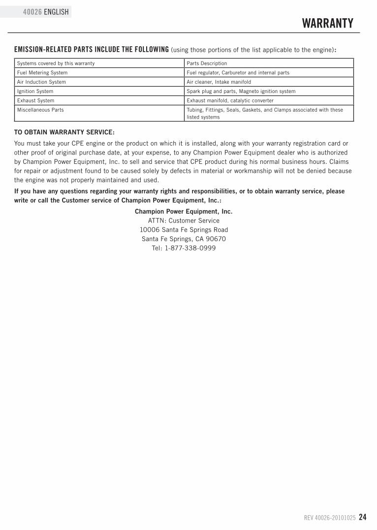
EMIssION-RELATEd PARTs INCLudE THE fOLLOWING (using those portions of the list applicable to the engine) :
TO OBTAIN WARRANTY SERVICE:
You must take your CPE engine or the product on which it is installed, along with your warranty registration card or other proof of original purchase date, at your expense, to any Champion Power Equipment dealer who is authorized by Champion Power Equipment, Inc . to sell and service that CPE product during his normal business hours . Claims for repair or adjustment found to be caused solely by defects in material or workmanship will not be denied because the engine was not properly maintained and used .
If you have any questions regarding your warranty rights and responsibilities, or to obtain warranty service, please write or call the Customer service of Champion Power Equipment, Inc.:
Champion Power Equipment, Inc.ATTN: Customer Service
10006 Santa Fe Springs RoadSanta Fe Springs, CA 90670
Tel: 1-877-338-0999
Systems covered by this warranty Parts Description
Fuel Metering System Fuel regulator, Carburetor and internal parts
Air Induction System Air cleaner, Intake manifold
Ignition System Spark plug and parts, Magneto ignition system
Exhaust System Exhaust manifold, catalytic converter
Miscellaneous Parts Tubing, Fittings, Seals, Gaskets, and Clamps associated with these listed systems