Embed Size (px)
Citation preview

3486 IEEE TRANSACTIONS ON MICROWAVE THEORY AND TECHNIQUES, VOL. 54, NO. 9, SEPTEMBER 2006
Monostatic Reflectivity Measurement of RadarAbsorbing Materials at 310 GHz
Anne Lönnqvist, Aleksi Tamminen, Juha Mallat, and Antti V. Räisänen, Fellow, IEEE
Abstract—This paper presents monostatic reflectivity measure-ments of radar absorbing materials at 310 GHz in a phase-holo-gram-based compact range. The radar cross-section methodwas used and the backscattered reflection was measured withhorizontal and vertical polarizations in plane-wave conditions.Transmission was also studied. The reflectivity was measured overan incidence angle of 0 –45 . The reflectivity of Thomas KeatingTerahertz RAM at normal incidence was found to be 56 dB—thesmallest of the studied materials. The reflectivity of carpet ma-terial measured was also below 40 dB and it was found to besuitable for use as an absorber. The results are in line with thoseavailable from previous studies of reflectivity and complementthem with new materials, frequency, and angle information.
Index Terms—Compact range, monostatic reflectivity, radar ab-sorbing materials, radar cross-section (RCS) method.
I. INTRODUCTION
RADAR absorbing materials are needed to suppress un-wanted reflections, e.g., in compact test ranges and to min-
imize radar cross section (RCS) of a target. Absorbers can alsobe used as beam dumps in quasi-optical systems and as cali-bration loads in radiometers [1], [2]. Application-specific ab-sorbing materials have been designed for these different pur-poses. Attenuation can be caused by electric or magnetic lossesand by the structure of the absorber.
In this paper, attention is concentrated on absorbers, whichcan be used when building a compact antenna or RCS measure-ment range for submillimeter wavelengths. Characteristics ofabsorbing materials need to be known when building a compactrange. With proper placement of absorbers, the amount of ab-sorbers needed can be minimized and low reflectivity level of thebackground can be assured. Possible standing waves can also besuppressed. For this purpose, we have characterized four com-mercially available radar absorbing materials and three carpets.The use of carpets as absorbers at submillimeter wavelengths isappealing due to their low price compared to the commerciallyavailable absorbing materials.
In most of the absorbers used in anechoic chambers,carbon-impregnated polyurethane foam is used to provide
Manuscript received January 23, 2006; revised June 1, 2006. This work wassupported in part by the Academy of Finland and Tekes under their Centre-of-Excellence Program. The work of A. Lönnqvist was supported by the Grad-uate School in Electronics, Telecommunication, and Automation, by the Jennyand Antti Wihuri Foundation, by the Foundation of the Finnish Society of Elec-tronic Engineers, by the Nokia Foundation, by the Foundation of Technology(Finland), and by the Emil Aaltonen Foundation.
The authors are with MilliLab, Radio Laboratory, The Smart and Novel Ra-dios Research Unit, Helsinki University of Technology, Espoo FI-02015 TKK,Finland (e-mail: [email protected]).
Digital Object Identifier 10.1109/TMTT.2006.881023
loss. The absorbers are usually shaped so that the geometricaltransformation from the free space to lossy medium providesa dielectric gradient and reduces reflections. Pyramidal andwedge-shaped painted absorbers are commonly used. A layerof low reflection paint is used to provide protection and toreduce the amount of carbon dust in the measurement range.These kinds of absorbers scatter more energy to the directionssatisfying the grating equation, as shown with measurementsin [3] for pyramidal and wedge-shaped absorbers below 18GHz and in [4] for a wedge-shaped Far-Infrared RadiationAbsorbing Material (FIRAM) at 584 GHz. However, usuallyelectromagnetic simulations cannot exactly predict the scat-tering behavior of absorbers and, therefore, it needs to beverified with measurements before designing their placementin a compact range.
Earlier, bistatic, and specular measurements of the absorbersinvestigated here have been carried out at MilliLab, HelsinkiUniversity of Technology, Espoo, Finland [5], [6]. However,these measurements were done in near field conditions. Nowthe campaign is completed with monostatic compact range mea-surements, where the absorber sample is placed into a plane-wave region and measured over an angle range of 45 fromthe normal of the absorber. The transmission of the absorbersis also measured. In [1] and [2], the reflectivity has been mea-sured only in the direction of the normal of the absorber, but forcompact antenna test range (CATR) design, more informationon the characteristics of the absorber are needed.
In the RCS method [7] used here, the absorber sample isfastened on a heavy metal backing plate, the plate is installedon a rotating fixture, and the RCS pattern of the ensemble isrecorded. The perfect reflection from the backside of the platecan be used as a reference and the characteristics of the ab-sorber can be evaluated by comparing the reflection from theabsorber to the reference. Since the result is obtained by com-paring these two reflections, the absolute amplitude of the RCSpattern does not need to be calibrated. The measurement rangeitself will be presented in more detail in Section II. In Section III,details of the absorber materials and the measurement are de-scribed. The results, discussion, and conclusion are presentedin Sections IV–VI, respectively.
II. COMPACT RCS MEASUREMENT RANGE
The measurement range used for absorber characterizationhas originally been designed for measuring RCS of scaledmodels [8]. In a compact range, we are able to evaluate the ab-sorber samples in more realistic conditions than with near-fieldmeasurements. The plane-wave region needed for RCS evalu-ation is created with a phase hologram [9], which transforms
0018-9480/$20.00 © 2006 IEEE
LÖNNQVIST et al.: MONOSTATIC REFLECTIVITY MEASUREMENT OF RADAR ABSORBING MATERIALS AT 310 GHz 3487
Fig. 1. Hologram-based test range. (RX = receiver; TX = transmitter).
Fig. 2. Closer view of the radar setup.
the spherical wave radiated by the feed into a plane wave. Asa diffractive element, the phase hologram is narrowband sowhen wanting to cover a wide range, several holograms needto be designed and manufactured. The region where the scaledmodel, or here, a sample of an absorber, is placed is what iscalled the quiet zone (QZ). The setup is shown in Fig. 1. Thedistance from the receiver/transmitter to the hologram and alsofrom the hologram to the target is 1 m.
The phase hologram is realized as a groove structure on athin Teflon plate. In this case, the phase-hologram operation isoptimized for operation at 310 GHz, which is suitable for ourcompact ranges. The changing depth of the grooves causes thephase modulation of the transmitted field. The hologram struc-ture of size 28 cm 24 cm was fabricated on a 5-mm-thickTeflon plate. The amplitude and phase variations of the QZ fieldare approximately 2 dB and 10 peak-to-peak, respectively. Thediameter of the QZ is 12 cm. Outside the QZ, the amplitude ofthe field drops quickly, approximately 10 dB when moving froma distance of 6 cm ( diameter) to 8 cm from the axis of theQZ.
The instrumentation is based on a millimeter-wave vectornetwork analyzer (AB Millimètre MVNA-8–350) with submil-limeter-wave extensions. Corrugated horns are used as transmit-ting and receiving antennas. A dielectric slab with 3-dB powerdivision is used as a directional coupler. The load absorber,which is made of Thomas Keating Terahertz (TK THz) RAM, isplaced on a translation stage to enable its proper placement. TKTHz RAM is also used around the transmitter and receiver, ascan be seen in Fig. 2. Additional absorbers were placed aroundthe setup before measurements to reduce reflections.
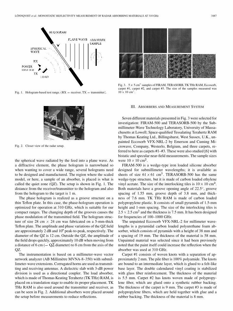
Fig. 3. 5� 5 cm samples of FIRAM, TERASORB, TK THz RAM, Eccosorb,carpet #1, carpet #2, and carpet #3. The size of the samples measured was10� 10 cm .
III. ABSORBERS AND MEASUREMENT SYSTEM
Seven different materials presented in Fig. 3 were selected forinvestigation: FIRAM-500 and TERASORB-500 by the Sub-millimeter-Wave Technology Laboratory, University of Massa-chusetts at Lowell; Space-qualified Tessalating Terahertz RAMby Thomas Keating Ltd., Billingshurst, West Sussex, U.K., un-painted Eccosorb VFX-NRL-2 by Emerson and Cuming Mi-crowave, Company, Westerlo, Belgium, and three carpets, re-ferred to here as carpets #1–#3. These were also studied [6] withbistatic and specular near-field measurements. The sample sizeswere 10 10 cm .
FIRAM-500 is a wedge-type iron loaded silicone absorberdesigned for submillimeter wavelengths; it is available assheets of size 61 61 cm . TERASORB-500 has the samewedge-type structure, but it is made of carbon loaded ethylenevinyl acetate. The size of the interlocking tiles is 10 10 cm .Both materials have a groove opening angle of 22.5 , groovespacing of 1.55 mm, groove depth of 3.8 mm, and thick-ness of 7.6 mm. TK THz RAM is made of carbon loadedpolypropylene plastic. It consists of small pyramids of 1.5-mmheight and 1-mm spacing. The size of the interlocking tiles is2.5 2.5 cm and the thickness is 7.5 mm. It has been designedfor frequencies of 100–1000 GHz.
The unpainted Eccosorb VFX-NRL-2 for millimeter wave-lengths is a pyramidal carbon loaded polyurethane foam ab-sorber, which consists of pyramids with a height of 38 mm anda spacing of 19 mm. The thickness of the material is 58 mm.Unpainted material was selected since it had been previouslynoted that the paint itself could increase the reflection when theabsorber was used at 310 GHz.
Carpet #1 consists of woven knots with a separation of ap-proximately 2 mm. The pile fiber is 100% polyamide. The knotsare bound to an intermediate layer, which is glued to a felt-likebase layer. The double calendared vinyl coating is stabilizedwith glass fiber reinforcement. The thickness of the materialis 5.5 mm. Carpet #2 has knots woven made of polypropy-lene fiber, which are glued onto a synthetic rubber backing.The thickness of the carpet is 9 mm. The carpet #3 is made ofpolypropylene fibers, which are held together with glue and arubber backing. The thickness of the material is 8 mm.

3488 IEEE TRANSACTIONS ON MICROWAVE THEORY AND TECHNIQUES, VOL. 54, NO. 9, SEPTEMBER 2006
Fig. 4. Sample of FIRAM-500 placed on a sample holder. Front and backviews. On the metal plate, the laser beam also used to assure accurate align-ment of the sample can be seen (indicated with an arrow).
Fig. 5. Reflection pattern of FIRAM-500 at horizontal polarization at 310 GHz.Grey line = wedges vertically, black line = wedges horizontally.
The sample of the absorber was placed on a sample holder(see Fig. 4). The support is a column made of extruded poly-styrene foam (Styrofoam). The dielectric constant of Styrofoamwas measured and found to be 1.048 at 310 GHz. Thus, the re-flections from the support column are so low that with currentmeasurement setup, it is not possible to separate them from thebackground reflection. We have been able to measure RCS downto 42 decibels relative to a squre meter (dBsm) for the verticalpolarization and 36 dBsm for the horizontal polarization [8].
The support column itself was placed on a rotation/translationstage, which enables rotation of the target and also movement ofthe target in the -direction. The reflection from the absorber isseparated from the background reflection by moving the targetin the -direction and, as a result, a periodic response is ob-tained. The field component caused by the moving absorber canbe evaluated from the variation of the amplitude and the phase[8].
An aluminum plate was placed behind the absorber sample.A laser beam was used to assure proper alignment of the plateand absorber. The beam was pointed to the aluminum plate froma distance of 1.2 m and the position of the plate was tuned untilthe transmitted and reflected beams converged. It was calculatedthat the angular alignment precision was better than 0.12 .
The transmission of the absorbers at 310 GHz was measuredduring QZ testing. The measured amplitude of the QZ field with
Fig. 6. Reflection pattern of TERASORB-500 at horizontal polarization at310 GHz. Grey line = wedges vertically, black line = wedges horizontally.
Fig. 7. Reflection pattern of TK THz RAM at horizontal polarization at310 GHz.
Fig. 8. Reflection pattern of Eccosorb VFX-NRL-2 and carpet #1 (grey line)at horizontal polarization at 310 GHz.
Fig. 9. Reflection patterns of two different samples of carpet #1.
an absorber (without the metal back plate) placed in front of thefield probe was compared to the amplitude without the absorber.The measured amplitude was averaged over 120 samples takenin a period of 1 min.
IV. MEASUREMENT RESULTS
The reflectivity of the absorber samples was measured overan incidence angle of 0 –45 . The measurements were doneboth at horizontal and vertical polarization at 310 GHz. Thewedge-type absorbers were measured in two positions, i.e.,

LÖNNQVIST et al.: MONOSTATIC REFLECTIVITY MEASUREMENT OF RADAR ABSORBING MATERIALS AT 310 GHz 3489
TABLE IMAXIMA AND MINIMA OF REFLECTIVITES OF THE INVESTIGATED MATERIALS AT 310 GHz
wedges horizontally and wedges vertically. Measured patternsfor FIRAM, TERASORB, TK THz RAM, Eccosorb, and carpet#1 are shown in Figs. 5–9. The maxima and minima of thereflectivity and transmission of all the materials investigatedare gathered in Table I. We were able to measure the reflectivitydown to 70 dB compared to the reflection from the reference.
When the wedges of FIRAM are vertical, i.e., against thepolarization, the absorber forms a reflection grid according toBragg’s equation (1)
(1)
where is the distance between wedges (i.e., parallel slits), isthe angle of the maxima, is an integer, and is the wavelength.Peaks predicted by (1) can be seen around angles 18 ( 40 dB)and 39 ( 45 dB) (see Fig. 5).
Between these maxima, the reflectivity level is below60 dB. The level of reflectivity in the direction of the normal
of the absorber is 31 dB. When the wedges are horizontal,the reflectivity is below 60 dB, except in the direction ofthe normal of the absorber it is a maximum of 30 dB. Thetransmission is quite high, i.e., 24 dB.
TERASORB has a fingerlike pattern at both positions (seeFig. 6). The performance is clearly better near the normal ofthe absorber when the wedges are vertical, i.e., against the po-larization, i.e., 41 dB versus 29 dB when the wedges arehorizontal. The peaks caused by the grid structure can be seen,but their level is a lot lower than for FIRAM, approximately
50 dB. The transmission is also lower, i.e., 33 dB.The fingerlike structure of the reflection pattern caused by the
pyramidal structure of TK RAM can be seen in Fig. 7. The levelof reflectivity in the direction of the normal of the absorber is
51 dB and below 50 dB in the other directions. The trans-mission is low, below 50 dB.
The same kind of fingerlike pattern was not seen when mea-suring Eccosorb (see Fig. 8). At submillimeter wavelengths, thepyramids of Eccosorb are very large compared to wavelength,therefore the diffraction peaks are so close to each other thatthey cannot be seen in Fig. 8. As the absorber is made of foammaterial, its structure is also not as uniform as, for example,the structure of TK RAM. The reflectivity of Eccosorb is low,below 50 dB for all angles, and the transmission is also below
50 dB. Overall performance of the Eccosorb absorber is ade-quate for use at submillimeter wavelengths.
The monostatic reflectivity level of carpet #1 is about thesame to all directions (see Figs. 8 and 9), i.e., it scatters en-ergy to all directions. The reflectivity is surprisingly low, below
40 dB. The transmission of carpet #1 is higher than that forcommercial absorbers, i.e., 17 dB. The levels of reflectivity ofdifferent samples of the same material are alike, as can be seenin Fig. 9. The samples are from different manufacturing batchesand also the color of the samples is different. The reflection pat-tern of carpet #2 is very similar. It does have one advantage,the transmission is lower, approximately 25 dB. Carpet #3 hasthe worst performance with the reflection in the direction of thenormal of the carpet being 20 dB, which can partly be due toits high transmission, measured to be 5 dB, so the metal platecan partly be seen through the carpet. To the other directions,the performance is about the same as for the other carpets, i.e.,scatters to all directions.
V. DISCUSSION
In these monostatic measurements, TK THz RAM performedbest among the materials investigated. Clearly it works better tocertain reflection angles and with proper placement of the ab-sorbers, reflectivity level better than 60 dB can be expected.In [2], the reflection in the direction of the normal has beenmeasured to be 48 dB at 406 GHz, and in [1], 42 dB at576 GHz and 35 dB at 672 GHz, thus the result obtained here;
51– 56 dB at 310 GHz is very well in line with the previousmeasurements. In [1] and [2], there was no information on re-flectivity to other angles than in the direction of the normal ofthe absorber.
Eccosorb VFX-NRL-2 also performed very well. It seemsto scatter energy to all directions just like the carpet materialsinvestigated. In [6], the material was investigated without thepyramids, i.e., the flat side of the absorber was measured, so theresults cannot be compared. Also, as stated in [3], if the pyra-mids are large compared to wavelength, even though absorbertips tend to scatter coherently, the absorber walls built of severalabsorber panels scatter incoherently and the reflectivity level ofa wall is considerably lower than that of a single panel, or ashere, part of one panel.
From the carpet materials, the best choice would be carpet #2due to its high attenuation in transmission measurements and

3490 IEEE TRANSACTIONS ON MICROWAVE THEORY AND TECHNIQUES, VOL. 54, NO. 9, SEPTEMBER 2006
low overall reflectivity level. This carpet had the best perfor-mance among the carpets also in bistatic measurements. Thematerial is inexpensive compared to the commercial absorbermaterials (by the order of tens of times). Since the need of ab-sorbing material in a large-sized compact range can be over500 m , this type of difference reduces the costs significantly.The reflectivity is still higher than for the best materials so theplacement of the carpets has to be designed carefully when usingthem together with better absorber materials.
The performance of TERASORB and FIRAM is strongly po-larization dependent. For both, the performance is good whenexcluding the peaks caused by the wedge-type structure. Withthis kind of material, even more attention has to be paid to properplacement since even a small mistake in placement can causea 20-dB difference. These absorbers did not perform as goodas expected. However, this can be due to their design, whichwas optimized to frequencies higher than 500 GHz. For FIRAM,the reflection in the direction of the normal was approximately
30 dB at 310 GHz and, in [4], it was measured to be approxi-mately 38 dB at 584 GHz. TERASORB and FIRAM are attheir best when used with one polarization only. In compactranges, this very seldom is the situation.
The reflection coming back to the transmitter was not mea-sured in [6] so it is not possible to do a direct comparison ofthe results, but the order of superiority is the same as in [6]with the exception of Eccosorb, which was measured withoutthe pyramids in the previous study. In the far-field situation, themaximum measured reflectivity is clearly lower than what wasmeasured with near-field measurements. In the monostatic mea-surements reported here, it was possible to eliminate the effectof background reflections better than those reported in [6] and,furthermore, direct coupling was not a problem in the measure-ments reported here. For compact ranges, absorber measure-ments done in plane-wave conditions can be estimated to re-semble a real-life situation better than results of measurementsdone in the near field of the absorber.
The test samples were relatively small and they filled the QZalmost entirely. Even though the metal plate was totally coveredwith the absorber, diffraction from the edges could have causedsome uncertainty to the measurement result though any clear in-dication of this kind of phenomena was not found. Getting largersamples of the materials to the tests or a smaller QZ diameterwould eliminate the possibility of this kind of effect showing inthe measurement results.
In the future, also making bistatic measurements in far-fieldconditions would be of interest. With a phase hologram setupcontaining two holograms on a moving axis, this would be pos-sible. This kind of measurement would give a better under-standing of the scattering behavior of the absorber. The cross-polarization performance of absorbers should also be tested.Low reflectivity may be due to energy transforming from onepolarization to another.
In this study, we have tested absorbers at only one frequency,namely, at 310 GHz. This is due to the narrowband behaviorof our hologram-based RCS measurement setup. However, webelieve that the results obtained are useful, and also demonstratehow a relatively simple measurement setup can be used to testabsorbers in far-field conditions at submillimeter wavelengths.
VI. CONCLUSION
Monostatic reflectivity of a set of absorbing materials was in-vestigated at 310 GHz at an angle range from the normal of theabsorber to 45 . As expected, TK THz RAM manufactured byThomas Keating Ltd. was found to have the best performance.Eccosorb VFX-NRL-2 also performed well, better than 50-dBattenuation to all angles. This is better than expected for an ab-sorber that is designed for the millimeter-wave region. The Ec-cosorb material investigated here was unpainted so carbon dustcan cause trouble in some applications. Since its pyramids arelarge compared to wavelength and absorber walls scatter inco-herently, it can be expected to perform even better when a largeabsorber wall is built.
A floor carpet had the next best performance, over 40-dBattenuation to all angles. This can be found adequate at least forthe noncritical places in the compact range. A combination ofall of these three, i.e., TK THz RAM, Eccosorb, and carpets, is agood compromise. Use of the carpets considerably brings downthe costs of building a measurement range.
ACKNOWLEDGMENT
The authors thank the members of the Millimeter WaveGroup, MilliLab/TKK Radio Laboratory, Helsinki Universityof Technology, Espoo, Finland, for their support and usefulconversations during this study. The authors also thank J. Häklifor the transmission measurements. The authors further thankE. Noponen for designing the hologram used in these experi-ments.
REFERENCES
[1] A. Murk, N. Kämpfer, and N. J. Keen, “Baseline measurements witha 650 GHz radiometer,” in Proc. 2nd Millim. Wave Technol. Applicat.:Antennas, Circuits, Syst, Workshop, Espoo, Finland, May 27-29, 1998,pp. 121–126.
[2] A. Murk, N. Kämpfer, and N. J. Keen, “Baseline issues in an airborne650 GHz radiometer,” in COST-712 Microw. Tech. Meteorol. Work-shop, Bern, Switzerland, Dec. 1999, pp. 42–51.
[3] B. T. DeWitt and W. D. Burnside, “Electromagnetic scattering by pyra-midal and wedge absorber,” IEEE Trans. Antennas Propag., vol. 36, no.7, pp. 971–984, Jul. 1988.
[4] R. H. Giles, A. J. Gatesman, J. Fitzgerald, S. Fisk, and J. Waldman,“Tailoring artificial dielectric materials at terahertz frequencies,” inProc. 4th Int. Space Terahertz Technol. Symp., Los Angeles, CA, Apr.1993, pp. 124–133.
[5] J. Säily, J. Mallat, and A. V. Räisänen, “Reflectivity measurements ofseveral commercial absorbers in the 200–600 GHz range,” Electron.Lett., vol. 37, no. 3, pp. 143–145, 2001.
[6] J. Säily and A. V. Räisänen, “Characterization of submillimeter waveabsorbers from 200–600 GHz,” Int. J. Infrared Millim. Waves, vol. 25,no. 1, pp. 71–88, Jan. 2004.
[7] E. F. Knott, J. F. Shaeffer, and M. T. Tuley, Radar Cross Section, 2nded. Norwood, MA: Artech House, 1993.
[8] A. Lönnqvist, J. Mallat, and A. V. Räisänen, “Phase hologram basedcompact RCS test range at 310 GHz for scale models,” IEEE Trans.Microw. Theory Tech., vol. 54, no. 1, pp. 2391–2397, Jan. 2006.
[9] J. Meltaus, J. Salo, E. Noponen, M. M. Salomaa, V. Viikari, A. Lön-nqvist, T. Koskinen, J. Säily, J. Häkli, J. Ala-Laurinaho, J. Mallat, andA. V. Räisänen, “Millimeter-wave beam shaping using holograms,”IEEE Trans. Microw. Theory Tech., vol. 51, no. 4, pp. 1274–1280, Apr.2003.

LÖNNQVIST et al.: MONOSTATIC REFLECTIVITY MEASUREMENT OF RADAR ABSORBING MATERIALS AT 310 GHz 3491
Anne Lönnqvist was born in Somero, Finland, in1977. She received the Master of Science (Tech.)(with honors) and Licentiate of Science (Tech.)degrees in electrical engineering from the HelsinkiUniversity of Technology (TKK), Espoo, Finland,in 2001 and 2004, respectively, and is currentlyworking toward the Doctor of Science (Tech.) degreeat TKK.
Since 2000, she has been a Research Assistantand Research Engineer with the Radio Laboratory,TKK. Her current research interests include mil-
limeter-wave measurement techniques with a focus on hologram applications.
Aleksi Tamminen was born in Ruotsinpyhtää,Finland, in 1982. He received the Bachelor’s (Tech.)degree in electrical engineering from the HelsinkiUniversity of Technology (TKK), Espoo, Finland, in2005 , and is currently working toward the Master ofScience (Tech.) degree at TKK.
He is currently a Research Assistant involvedwith millimeter-wave measurement projects with theRadio Laboratory, TKK.
Juha Mallat was born in Lahti, Finland, in 1962. Hereceived the Master of Science (Tech.) (with honors),Licentiate of Science (Tech.), and Doctor of Science(Tech.) degrees in electrical engineering from theHelsinki University of Technology (TKK), Espoo,Finland, in 1986, 1988, and 1995, respectively.
Since 1985, he has been with the Radio Labo-ratory (and its Millimeter Wave Group), TKK, as aResearch Assistant, Senior Teaching Assistant, andResearch Associate until 1994. From 1995 to 1996,he was a Project Manager and Coordinator involved
with an education project between TKK and the Turku Institute of Technology.Since 1997, he has been a Senior Scientist with the Millimetre Wave Labora-tory of Finland (MilliLab), European Space Agency (ESA) External Laboratory,Helsinki, TKK, with the exception of a period of one year from 2001 to 2002when he served as a Professor (protem) of radio engineering with TKK. Hisresearch interests and experience cover various topics in radio-engineering ap-plications and measurements, especially in millimeter-wave frequencies. He hasalso been involved in building and testing millimeter-wave receivers for spaceapplications.
Antti V. Räisänen (S’76–M’81–SM’85–F’94)received the Master of Science (Tech.), Licentiateof Science (Tech.), and Doctor of Science (Tech.)degrees in electrical engineering from the HelsinkiUniversity of Technology (HUT), Espoo, Finland, in1973, 1976, and 1981, respectively.
In 1989, he was appointed Professor Chairof Radio Engineering, HUT, after holding thesame position as an Acting Professor in 1985 and1987–1989. He has been a Visiting Scientist andProfessor with the Five College Radio Astronomy
Observatory (FCRAO), University of Massachusetts at Amherst (1978–1981),Chalmers University of Technology, Göteborg, Sweden (1983), Departmentof Physics, University of California at Berkeley (1984–1985), Jet PropulsionLaboratory, California Institute of Technology, Pasadena (1992–1993), andParis Observatory and University of Paris 6 (2001–2002). He currently super-vises research in millimeter-wave components, antennas, receivers, microwavemeasurements, etc. at the Radio Laboratory, HUT, and Millimetre WaveLaboratory of Finland (MilliLab—European Space Agency (ESA) ExternalLaboratory). The Smart and Novel Radios Research Unit (SMARAD), HUT(which he leads), obtained in 2001 the national status of Center of Excellencein Research from The Academy of Finland after competition and internationalreview. He has authored and coauthored over 400 scientific or technical papersand six books, most recently, Radio Engineering for Wireless Communicationand Sensor Applications (Artech House, 2003). He also coauthored the chapter“Radio-Telescope Receivers” in Radio Astronomy (Cygnus-Quasar Books,1986, 2nd ed.).
Dr. Räisänen was secretary general of the 12th European Microwave Confer-ence in 1982. He was chairman of the IEEE Microwave Theory and Techniques(MTT)/Antennas and Propagation (AP) Chapter in Finland from 1987 to 1992.He was conference chairman for the 22nd European Microwave Conference in1992, and for the “ESA Workshop on Millimeter Wave Technology and Appli-cations” in 1998. From 1995 to 1997, he served on the Research Council forNatural Sciences and Engineering, Academy of Finland. From 1997 to 2000, hewas vice-rector for research and international relations of HUT. From 2002 to2005, he was an associate editor for the IEEE TRANSACTIONS ON MICROWAVE
THEORY AND TECHNIQUES.