Embed Size (px)
Citation preview

(NASA-CR-}64Zf_3) NGNL INLAR R@T__RnYNA_ [C S
A_!4LY_[q Final R_eport (Texas A_M univ.)
'_o p CSCL 13[
,_ 3/37
Ngg-14_44
NONLINEAR ROTORDYNAMICS ANALYSIS
prepared for
George C. Marshall
Space Flight CenterAlabama 35812
under
CONTRACT NAS8 - 37465
Principal Investigator
Sherif T. Noah
Mechanical Engineering Department
Texas A&M University
College Station, Texas 77843
February 1991
https://ntrs.nasa.gov/search.jsp?R=19920005126 2018-06-02T18:45:48+00:00Z
TABLE OF CONTENTS
ABSTRACT
I. INTRODUCTION
• Background
• Objectives and Outline of Study
II. ANALYSIS METHODS AND RESULTS
• STEADY STATE RESPONSE AND STABILITY
(i) One and Two Dimensional Systems
(ii) Multi-Disk Rotor Systems
• NONLINEAR TRANSIENT ANALYSIS
III. CONCLUSIONS AND RECOMMENDATIONS
• SUMMARY AND CONCLUSIONS
(i) Steady State Analysis
(ii) Transient Analysis
• RECOMMENDATIONS
ACKNOWLEDGEMENT
REFERENCES
APPENDIX A
"Bifurcation Analysis for a Modified Jeffcott Rotor
with Bearing Clearances"
APPENDIX B
"Response and Bifurcation Analysis of MDOF Rotor
System with a Strong Nonlinearity"
APPENDIX C
"A Convolution Approach for the Transient Analysis
of Locally Nonlinear Rotor Systems"
Page
i
1
1
2
4
4
4
7
7
12
12
12
14
19
21
21
24
46
82

ABSTRACT
Effective analysis tools have been developed for predicting the nonlinear
rotordynamic behavior of the SSME turbopumps under steady and transient operating
conditions. Using these methods, preliminary parametric studies have been conducted on
both generic and actual HPOTP (high pressure oxygen turbopumps) models. In particular,
a novel modified harmonic balance/alternating Fourier transform (HB/AFT) method was
developed and used to conduct a preliminary study of the effects of fluid, bearing and seal
forces on the unbalanced response of a Multi-disk rotor in presence of bearing clearances.
A cornputer program was developed and made available to NASA, Marshall. The method
makes it possible to determine periodic, sub-, super- synchronous and chaotic responses of
a rotor system. The method also yields information about the stability of the obtained
response, thus allowing bifurcation analyses. This provides a more effective capability for
predicting the response under transient conditions by searching in proximity of resonance
peaks. Preliminary results were also obtained for the nonlinear transient response of an
actual HPOTP model using an efficient, newly developed numerical method based on
convolution integration. A computer program was developed and made available to NASA
Marshal Flight Center. Currently, the HB/AFT is being extended for determining the
aperiodic response of nonlinear systems. Initial results shows the method to be promising.
5_

I. INTRODUCTION
Background:
Modern mechanical systems are being recently designed for higher performance,
reliability and smooth operation within compact configuration. These requirements often
cause significant nonlinear effects which could not be predicted with linear models.
Therefore, a more complete picture of their nonlinear dynamic characteristics is required
to enhance their efficient design, refinement, monitoring or maintenance.
Modern complex rotating machinery, such as the turbopumps of the space shuttle
main engines (SSME), contain various sources of strong nonlinearities. These include
clearances and nonlinearity of rolling elements, rubbing in splines and in built-up rotor
segments, rubbing at seals and rotor blades, viscous damping and various fluid effects.
Observed nonlinear behavior of actual rotor systems include jump discontinuities [I], large
subsynchronous motion, [2] - [4], quasi-periodic and possible chaotic motion [5]. As stated
by Nataraj and Nelson [6], the future developments in modern machines heavily depends
on the ability to identify, understand mathematically and analyze systems involving nonlinear
components. This is particularly the case for the proper development, monitoring and
analysis of the SSME turbopumps.
Quite often, it is essential to determine the steady state periodic response of rotor
systems in the form of self excited limit cycles or forced motion due to rotating imbalance.
Accurate prediction of the nonlinear periodic responses and their stability plays a central
role in developing a complete picture of the dynamic behavior of nonlinear rotor systems
as function of their parameters.

Severalmethodshaverecently beenadvancedfor determining the periodic response
of low order nonlinear rotor systems,[7] - [10]. For application to large, multi-disk rotor
systems,Nataraj and Nelson [6] developed a periodic solution method based on a
collocation approach for the responseof the rotor. They utilized a subsystemapproach to
reducethe sizeof the resulting systemof algebraicequations. Ehrich [11] recently analyzed
high order subharmonicresponseand chaos [12] using numerical integration for Jeffcott
rotor with a bearing clearance.
Few analystshave addressedthe stability of periodic or subharmonicresponsesof
nonlinear rotor systemsdespite its considerablesignificancein predicting the responseof
modern, high performance systems. Most of the stability or bifurcation analyseswere
concentratedon one dimensional (rectilinear) problemswhere solution forms are assumed
a priori (Shaw and Holmes [13], and Natsiavaas[14]). Theseapproachesare very difficult
or not feasible to extend to the two dimensional nonlinear rotor problems.
Complete characterization of the dynamic behavior must include determining the
steady state responsesand their bifurcation as function of the system parameters. In
addition, the transient responseof the nonlinear systemhasto bedetermined aspart of any
complete dynamic analysisof the system.
Objectives and Outline of Study
The main objective of this study was to develop reliable and efficient analytical-
computational methods of the nonlinear dynamic analysis of large, rotor-housing systems
such as the turbopumps of the space shuttle main engines (SSME), and some aspects were
then examined to be of the nonlinear behavior of a general multi-disk rotor-housing system.
2

In the present study, HB (Harmonic Balance)/AFT (Alternating Frequency-Time)
method has been developed. Using the method, a study is made of the dynamics and
stability of simplified models of the HPOTP (High Pressure Oxygen Turbo Pump) of the
SSME (Space Shuttle Main Engine) including clearances between the bearings' outer races
and their supports. The method employs an explicit Jacobian form in an iterative procedure
which ensures convergence at all parameter values. A dynamic reduction technique [15] is
used with the HBM to reduce the system nonlinear differential equations to linear algebraic
equations involving only the nonlinear coordinates.
A recently developed convolution approach by the present author for the non-linear
transient analysis was carefully tested against direct integration techniques and proved more
robust and efficient. Using the HB/AFT method, the response resonances of a multiple-
disk rotor as function of the rotor spinning speed (critical speeds) can be located. The
convolution approach can then be used effectively to determine the transient response in
passing through these critical speeds.

II. ANALYSIS METHODS AND RESULTS
STEADY STATE RESPONSE AND STABILITY
(i) One and Two Dimcnsi0nal Systems:
The dynamic behavior of strongly nonlinear mechanical systems with piecewise-linear
or piecewise-smooth nonlinearities is studied using a newly developed HB (Harmonic
Balance) with an AFT (Alternating Frequency Time) robust and efficient algorithm.
employing the harmonic balance approach,
transformed to nonlinear algebraic equations.
By
arethe nonlinear differential equations
Two iterative techniques are available for
solving the nonlinear algebraic equations. These are the Newton-Raphson method and a
certain version of the Quasi-Newton Algorithm. The Newton-Raphson algorithm requires
a laborious and complex calculation of a Jacobian matrix and has a narrow range of initial
guesses for achieving convergence. However, the algorithm has superior convergence speed
as compared to the corresponding Quasi-Newton method.
The development of the method and its application to an oscillator interacting
through a gap with a flexible stop (see Figure 1) can be found in a paper [16], accepted for
publication in the Journal of Applied Mechanics of the American Society of Mechanical
Engineers (ASME). The method was also applied to a modified Jeffcott rotor model (see
Figure 2) supported on bearings, with clearances (see appendix [A] which was also published
as a paper in "Nonlinear Dynamics", [17]).
A bifurcation analysis method, based on Flouqet's theory, was also developed for
determining the stability of the obtained periodic solutions. For the stability analysis,
Poincare mapping is utilized to obtain the fixed points corresponding to the periodic
4

Figure l-a Oscillator with a gap
v
Figure l-b Piecewise-linear restoring force of
oscillator

y2
Figure 2. Jeffcott rotor model with a bearing
clearance,
solutions (or limit cycles). Small perturbation around the periodic solutions (fixed points)
is performed in order to analyze their stability. A first order Jacobian around a fixed point
is calculated using numerical integration to obtain the associated monodromy matrix. The
eigenvalues of the monodromy matrix are analyzed to determine the bifurcation type (cyclic
fold, secondary Hopf or period multiplying).
The bifurcation analysis allows determining ranges of parameters at which the
response of a given rotor system would become subsynchronous or chaotic.
(ii) Multi-Disk Rotor Systems
The HB/AFT method was also applied to a two-disk rotor system (see Figure 3)
containing a bearing clearance [18,19]. The method generalizes the author's early work
[20,21]. Results were obtained for the synchronous, sub-synchronous and chaotic response
of the system. The bifurcation analysis developed for this case was also used for predicting
the onset of qualitative changes in the dynamic behavior of the system. The extended
HB/AFT and bifurcation analysis extended for application to the two-disk rotor system
considered, as well as the sample results obtained, are included in Appendix B. The work
in this appendix was also accepted for publication in "Nonlinear Dynamics" Journal [18].
A computer program for this case was developed and made available to NASA, Marshall
which, if needed, can be readily modified for modeling the turbopumps of the SSME.
NONLINEAR TRANSIENT ANALYSIS
A convolution approach first reported by Noah [22] and Noah, el. al. [23] was further
refined and applied to the transient analysis of the generic model shown in Figure 4. A
general purpose computer program is written based on this approach, along with a user

LI
KB
radial clearance
L2 1.3
Figure 3. Multi-disk rotor model with a bearing clearance.

ROTOR
I-lOUSING
z F2 ,., F, Fs
1 2 13 14 15 16 17 18 19 20
(
Ksz, Ksz,
ROTOR: Shaft diameter: OD = 3.0 inches,
Material: Steel, E = 3.0 x l0 t psi
Joint length = 3.0 inches
Rotor length = 27.0 inches
HOUSING: Housing/rotor weight ratio = 6/1
(EI)R = 1.1928 × l0 s lb in s
(EI)H = 2.4 × 10⁸ Ib in _
F, (0 = '_ e¢__os¢t
F,(t) = m, e¢' sinett
F_(t) = m_e¢2_osetY,(t) = 'm ed_si.¢t
F,(t) = m_e¢'_oset
Ksz, = 4.0 x 10 4 Ib/in
Ksyt = 5.0 x 10⁴ Ib/in
Ksz, = 5.0 × 10 4 Ib/in
KsY2 = 1.5 × l0 s lb/in
KG = 5.0 × l0 s Ib/in
C_ = 0.0
ID = 0.0 inch
Figure 4. The generic model of the SSME turbopump

manual and was provided to NASA, Marshall.
The convolution approach can be applied to a locally nonlinear general rotor housing
system with rotor imbalance during start-up or shut-down.
coordinates are used to represent both housing and rotor.
In the present work, eigen-
The local nonlinearities were
taken as bearing deadband clearances at the rolling element bearings which support the
rotor in its housing. The integral formulation of the rotor motion is represented by its
transition matrix and that of the housing by a convolution integral (based on the housing's
impulse response).
The convoluted impulse response can only be applied to a system of uncoupled
equations while the transition matrix formulation, in addition, can be applied to coupled
equations. The transition matrix can therefore be applied to coupled dynamical systems
represented by their physical coordinates or, in case of rotors, coupled by the gyroscopic
terms in otherwise decoupled modal representation.
Sample of the various tests conducted on the convolution method, to test its accuracy
and efficiency, is presented in Figures 5 and 6 for the generic model of Figure 4 under
transient loading. It can be seen that the method is more robust and efficient than direct
numerical integration.
More complete presentation of the method and the transient response is included in
Appendix C. A paper [24] was also published based on this appendix in the ASME Journal
of Applied Mechanics.
10

50O
--. 40O1:3Z00i,I
3O0 -
laJ
1--
200
o_(D
IO0
LINEAR
+ DUHAMEL INTEGRAL
-*-- TRANSITION MATRIX
-•- RUNGE KU'rI'A
--e-- HYBRID
i
i
#
g
i
t
i
#
J
i
n
!
r
i
i
• /
• /
ii •
• /
- ° .... If /
_ _r ........... I _
0 I I I I I J
0.0 0.2 0.4 0.8 0.8 1.0 1.2
TIME STEP SIZE (X 1000 SECOND)
1,4
Figure 5. Accuracy of hybrid method and Runge Kutta method
4oo
zOobJ_9
w
o_
_oo -1
200 -
100 -
NONLINEAR
+ HYBRID
-.I.- RUNGE KLITTA
II
I
\ /
\ /
\ /
tI
II
II
Il
I
! ! I I : I (
0.0 0.2 0.4 0.6 0.8 1.0 1.2
TIME STEP SiZE (X 1000 SECOND)
1.4
Figure 6. CPU time of hybrid method and Runge Kutta method
Ii
III. CONCLUSIONS AND RECOMMENDATIONS
SUMMARY AND CONCLUSIONS
(i) Steady State Analysis:
A robust iterative numerical procedure based on the HBM/AFT method has been
developed for obtaining the periodic response of a large rotor/housing system containing
bearing clearances. Modern bifurcation theory is utilized to characterize the dynamic
behavior of the system. A bifurcation analysis method is developed which provides
boundaries of parameter regions at which rotor whirling pattern changes its shape rapidly,
resulting in the occurrence of subharmonic, aperiodic or possible chaotic motion.
Results on the effects of parameters on a SDOF (Single Degree of Freedom) system
with piecewise-linear response show that, for some combinations of these parameters, the
system response exhibits both period doubling and saddle-node bifurcations. Chaotic motion
was also observed for finite stiffness ratios. The stability analysis, along with the harmonic
balance-based method provide a very powerful tool for better understanding of the behavior
of systems with clearances.
The main results obtained using the HBM/AFT approach with a nonlinear Jeffcott
rotor 1 with a bearing clearance can be summarized as follows [17]:
1. Increasing the dimensionless support stiffness ratio, *,, causes flip bifurcation
to occur which produces period doubled whirling motion (subsynchronous
motion).
1A Computer program based on this work was submitted to NASA, Marshall.
12

2. For the same a and a nondimensional frequency_ ratio, t_, an increase in the
damping ratio, ¢, leads to elimination of the subharmonic motion.
3. With higher values of a, chaotic whirling motion is feasible.
4. Limited results obtained concerning the effect of Coulomb friction indicate
that the coefficient of friction, g, has little effect on the subharmonic
response. However, higher g could eliminate the subharmonics near flip
(period doubling) bifurcation boundaries.
5. Increasing the nondimensional cross coupling stiffness ratio _, leads to a Hopf
bifurcation which could result in a.periodic whirling.
A further developed HBM, using a DFT (Discrete Fourier Transform)/IDFT
(Inverse Discrete Fourier Transform), is employed to obtain the steady-state periodic
response for MDOF (multi-degree of freedom) rotor systems with bearing clearances
(piecewise-linear type nonlinearity). 2 A dynamic reduction (impedance) technique [15] is
utilized to reduce the system to only those of the nonlinear coordinates. The stability
analysis is performed via perturbation of the obtained periodic solutions. The reduced and
approximated system parameters (mass, damping, and stiffness) are calculated from the
determined harmonic coefficients.
A simple MDOF rotor system with a bearing clearance is used for illustration of the
method. The results obtained show that: i) the HB/AFT method, as developed here, is
robust and efficient; ii) the method leads to accurate bifurcation boundaries for nonlinear
MDOF rotor systems and, furthermore; iii) the method can in general be applied to MDOF
rotor systems with piecewise-smooth or polynomial type nonlinearities at the bearing
2A computer program based on this work was submitted to NASA, Marshall.
13

supports.
In summary, the major advantages of the HB/AFT approach are:
a) it can provide steady-state periodic solution as well as steady-state quasi-
period solutions using modified DFT/IDFT algorithms.
b) its formulation is neither problem nor response pattern dependent, except for
selecting the least appropriate numbers of harmonics for the Fourier
expansions.
c) it can drastically reduce the computational time while providing high
computational accuracy. Especially for nonlinear MDOF systems with lower
damping, this approach is much more powerful in delineating the steady-state
solutions efficiently.
d) it enables perturbation of the determined periodic solution so that the
resulting linear ordinary differential equation with periodic coefficient would
yield information about the stability employing Floquet theory. Approximate,
but accurate, stability information can then be obtained.
e) using modern dynamical theory, detailed bifurcation boundaries and their type
(such as flip, Hopf and fold) can be easily calculated from the perturbed
periodic solution as function of the system parameters.
f) by observing the unstable solutions, bifurcation boundaries can be easily
obtained as function of system parameters.
(ii) Transient Analysis:
The hybrid convolution approach, further developed in this study, is shown to provide
an efficient and accurate closed form integral formulation for determining the transient
14

response of linear systems coupled through local nonlinearities associated with friction and
clearances. A typical application in which the present method proved quite effective is the
determination of the transient response of a generic model of the high pressure oxygen
turbopump (HPOTP) of a space shuttle main engine (SSME) in presence of bearing
clearances (see Appendix C). 3
The use of the transition matrix is successful in allowing the representation of rotor-
system involving skew-symmetric matrices of gyroscopic loads or other nonconservative
systems with general velocity dependent matrices. A convolution integral would represent
quite effectively other systems with normal modes, such as the housing of the HPOTP or
other non-rotating, proportionally damped structures. An application is also made to a
generic model of the high pressure oxygen turbopump (HPOTP) of a space shuttle main
engine (SSME) in the presence of bearing clearances, constituting the local nonlinearities.
Two iterative techniques, the Jacobi method and the Gauss-Seidel method, were
studied. Both were able to correct the predicted coupling forces and converge to the correct
force magnitudes with a desired accuracy. The Gau_s-Seid¢l method is more efficient in
CPU time especially for a system with large time step and large external forces. For a
system with very small external forces, the advantage will not be significant. However, the
solution has to be formulated differently so as to accommodate a given type of nonlinear
component. If the convolution method is applied to a system with a specific nonlinear
component only, Gauss-Seidel scheme could be a better choice. On the other hand, the
Jac0bi scheme is more flexible in its application. Once the equations of a rotor and its
housing are derived, they are ready for use with almost all other types of coupling
3A computer program based on this work was submitted to NASA, Marshall.
lq

components.
A generic model of the HPOTP of the SSME was used to test the transient method
and conduct parametric studies, typical of nonlinear rotor/housing systems with bearing
clearances.
As typical of the effectiveness of the convolution method, firstly, the accuracy and
CPU time are studied using both the hybrid convolution approach and Runge Kutta 4th
order method. The results show for the given triangular load used in [24] and included in
Appendix C that:
1. For a fixed tolerance (1 x 10-s), the hybrid convolution method is faster and
more accurate.
hybrid method.
The CPU time for the Runge Kutta is 1.42 times of the
For more meaningful comparison, the accuracies of the
Runge Kutta and convolution methods are made closer by reducing the
allowable tolerance for the Runge Kutta to 1 x 10 14. The CPU time for the
Runge Kutta increases quickly from 1.42 times of the hybrid method's CPU
to 4.23 times.
2. The hybrid convolution method is also more robust than the Runge Kutta
method. The Runge Kutta algorithm failed to converge for time increments
greater than 2 x 10 -5 seconds. However, the hybrid method will diverge when
the time step size is larger than 3.3 x 10 -5 seconds.
Secondly, the convolution method is shown to have the potential as a useful tool for
determining transient response. For the generic model of the HPOTP, three nonstationary
cases have been studied [25]. One is a linear model with no gap. In this case, a closed form
solution can be used directly. The other two are nonlinear cases with small and large gaps
16

(gap size 5 x 10 .4 and 1 x 10.3 inches respectively). The gaps are considered as the small and
large bearing clearances. The study shows:
1. The reaction force in the deceleration period is much higher than that in the
acceleration period. One of the reasons is that the response in the
deceleration period has more time to build up since the absolute value of the
deceleration is smaller than that of the acceleration.
2. The small gap reduces the approximate first linear critical speed by 9%.
However, the large gap reduces the speed by 18%.
3. The small gap reduces the amplitude of the peak bearing forces at the first
critical speed of the linear case by 45.2% in bearing 1 and 30.6% in bearing
2. The large gap reduces the amplitude of the peak bearing forces at the first
critical speed of the linear case by 49.8% in bearing and 34.9% in bearing 2.
The larger gap causes more reduction in peak forces.
4. In contrast to the first critical speed, the second critical speed and its
corresponding peak forces in the two bearings in the deceleration period of
these three cases are not significantly influenced by the existence or the size
of the gap. The average reductions are 0.9% for critical speeds and 2.4% for
the corresponding forces.
5. The peak force at the second critical speed is higher than that at the first
critical speed. The ratio is 1.78 and 3.94 times in bearings 1 and 2,
respectively, for the linear case. For the nonlinear case, the ratios are much
higher. For the small gap, the ratios are 3.4 and 5.8 in bearing 1 and 2,
17

respectively. For the large gap, the ratios are 3.7 and 6.2 in bearing 1 and 2,
respectively.
The convolution formulation allows accommodating with ease changes in the
nonlinear or linear coupling parameters among the various linear subsystems involved.
Besides bearing clearances, other cases of local nonlinearities involving dry friction and
impacts were also studied in [25].
18

RECOMMENDATIONS
The newly devisedHB/AFT method proved to be effective in obtaining the steady
state solutions for multi-disk rotor systems. Although the impedance (dynamic
condensation) method [22,15] is utilized to reduce the systems' equations, the reduction was
only possible in physical coordinate systems. In order to adopt the method to generalized
coordinate systems, modal representation utilizing a drastically truncated set of modes will
be necessary. Further development of the HB/AFT method should be made in order to
allow for better reduction techniques in modal coordinates. In addition, the so called
internal resonances (in which nonrational relation between the various modes exists) need
to be investigated as related to the turbopumps of the SSME.
Further study is needed to complete the development of a preliminary method
obtained in this study concerning quasi-periodic response, and to generalize the HB/AFT
method to conduct parametric studies on the SSME turbopumps under various operating
conditions.
Modern studies have revealed the significance of predicting what is labeled "crisis".
This is a generalization of the jump behavior in nonlinear systems. A preliminary study was
made and limited results were obtained during the course of the present study. It is
recommended that further study be pursued in which the "crisis behavior" in piecewise-
smooth systems (specially in applications to rotordynamics) is peculiar. In this connection,
the HB/AFT method could prove to be very effective.
For the transient analysis, further work should be made on the analysis and behavior
of rotor systems with bearing clearances and rubs. This could include the following:
a. Use approximate methods to replace local nonlinearities with linear
19
components and then use closed form convolution representation for the
solutions.
b. Use other possible iterative techniques, possibly incorporating the Gauss-
Seidel technique.
c. Develop other means of increasing the efficiency of the method, including the
use of predictor-corrector and other algorithms.
d. Adapt the HB/AFT method to determine domains of attractions of the
nonlinear rotor system.
e. Extend the method for application to other local nonlinearities, e.g. Coulomb
friction rubs at seals, turbine blades, rotor shrink fits and to impacts due to
intermittent contacts.
f. Conduct parametric studies of the turbopumps of the SSME using the current
and modified versions of the computer programs provided to NASA, Marshall,
developed in this study to examine the significance of the various nonlinear
phenomena.
g. Explore the HB/AFT method role in experimental verification, identification,
and monitoring of the SSME systems.
Finally, direct comparison should be made of the techniques reported here to those
currently used throughout industry. It is anticipated that the techniques described here will
yield more information about the dynamic behavior of nonlinear rotor systems in an efficient
and systematic manner.
2O

ACKNOWLEDGEMENT
This work was carried out as part of a research project supported by NASA, Marshall
Flight Center, under Contract No. NAS8-37465. The authors are grateful to Thomas Fox,
the technical monitor, for his enthusiastic support and interest.
REFERENCES
. Ehrich, F. F., 1966, "Subharmonic Vibrations of Rotors in Bearing Clearances,"
ASME paper No. 66-MD-1.
. Bently, D., 1979, "Forced Subrotative Speed Dynamic Action of Rotating Machinery,"
ASME paper No. 74-PET-16.
. Muszynska, A., 1984, "Partial Lateral Rotor to Stator Rubs," Proceedings of the Inst.
Mech. Engrs. 3rd Intl. Conf. on Vibrations in Rotating Machinery, Univ. of York, 11-
13 Sept., pp. 327-335.
o Beatty, R. F., 1985, "Differentiating Rotor Response Due to Radial Rubbing,"
(ASME) Journal of Vibration, Acoustics, Stress and Reliability in Design, Vol. 107,
pp. 151-160.
5. Neilson, R. D., and Barr, A. D. S., 1988, "Response of Two Elastically Supported
Rigid Rotors Sharing a Common Discontinuously Non-linear Support," Proceedings
of the Institution of Mechanical Engineers, Heriot-Watt University, 13-15 Sept., pp.
589-598.
. Nataraj, C. and Nelson, H. D., 1987, "Periodic Solutions in Rotor Dynamic Systems
with Nonlinear Supports: A General Approach," American Society Mechanical
Engineers Design Conference, October.
. Yamamoto, T. T., 1954, "On Critical Speeds of a Shaft," Memoirs of the Faculty of
Engineering, Nagoya (Japan) University, Vol. 6, No. 2
. Childs, D. W., 1982, "Fractional-Frequency Rotor Motion due to Nonsymmetric
Clearance Effects," ASME Journal of Ener_ and Power, Vol. 104, pp. 533-541.
21

.
10.
11.
12.
13.
14.
15.
16.
17.
18.
19.
20.
Saito, S., 1985, "Calculation of Nonlinear Unbalance Response of Horizontal Jeffcott
Rotors Supported by Ball Bearings with Radial Clearances," ASME paper No. 85-DET-33.
Choi, Y. S. and Noah, S. T., 1987, "Nonlinear Steady-State Response of a Rotor-
Support System," ASME Journal of Vibration. Acoustics. Stress and Reliability in
D_, Vol. 109, pp. 255-261.
Ehrich, F. F., 1988, "High Order Subharmonic Response of High Speed Rotors in
Bearing Clearance," ASME Journal of Vibration, Acoustics, Stress and Reliability in
D_, Vol. 110, pp. 9-16.
Ehrich, F. F., 1990, "Some Observations of Chaotic Vibration Phenomena in High
Speed Rotor-Dynamics," accepted for publication in the ASME J, of Vibration and
Acoustics.
Shaw, S. W. and Holmes, J. P., 1983, "A Periodically Forced Piecewise-Linear
Oscillator," Journal of Sound and Vibration, Vol. 108, pp. 129-155.
Natsiavas, S., 1989, "Periodic Response and Stability of Oscillators with Symmetric
Trilinear Restoring Force. Journal of Soond and Vibration, Vol. 134, pp. 315-331.
Fan, U. J. and Noah, S. T., 1990, "Vibration Analysis of Rotor Systems Using
Reduced Subsystem Models," AIAA Journal of Propulsion and Power, Vol. 102, pp.360-368.
Kim, Y. B. and Noah, S. T., 1990, "Stability and Bifurcation Analysis of Oscillatorswith Piecewise-linear Characteristics: A General Approach," accepted for publication
in the ASME J. of Applied Mechanics.
Kim, Y. B. and Noah, S. T., 1990, "Bifurcation Analysis for a Modified Jeffcott Rotor
with a Bearing Clearance," Nonlinear Dynamics Journal, Vol. 1, pp. 221-241. Also
presented at the llth U.S. National Congress of Applied Mechanics, May 21-25,
1990, Universityi of Arizona, Tucson, AZ.
Kim, Y. B. and Noah, S. T., 1991, "Response and Bifurcation Analysis of MDOF
Rotor System with a Strong Nonlinearity," to appear in N0nlin¢ar Dynamics.
Kim, Y. B. and Noah, S. T., 1990, "Bifurcation Analysis for a Multi-Disk Rotor
System with Bearing Clearances," presented at the Third Conference on Nonlinear
Vibrations, Stability and Dynamics of Structures and Mechanisms, VPI and State
University, Blacksburg, VA, June 25-27.
Kim, Y. B., Noah, S. T. and Choi, Y. S., 1990, "Periodic Response of Multi Disk
Rotors with Bearing Clearances," Journal of Sound and Vibration, Vol. 143, No. 3.
22

21.
22.
23.
24.
25.
Kim, Y. B. and Noah, S. T., 1989, "Steady-State Analysis of a Nonlinear Rotor-
Housing System," to appear in ASME Journal of Torb0machinery, also presented at
the Gas Turbine and Aeroengine Congress, June 11-14, 1990, Brussel, Belgium.
Paper No. 90-GT-328.
Noah, S. T., 1986, "Hybrid Methods for Rotordynamic Analysis," Final NASA Report,
G. C. Marshall Space Flight Center, Alabama, under contract No. NAS8-36182,
December, 1986.
Noah, S. T., Chiang, I. F., and Kim, Y. B., 1988, "Dynamic Analysis of Nonlinear
Rotor/Housing Systems," MSFC Advanced High Pressure O2/H 2 Technology
Conference Proceedings, G. Marshall Space Flight Center, Huntsville, Alabama.
Chiang, I. F. and Noah, S. T., 1990, "A Convolution Approach for the Transient
Analysis of Locally Nonlinear Rotor Systems," ASME J. Applied Mechanics. Also
presented at the ASME Winter Annual meeting, November, 1990, Dallas, Texas.
Chiang, I. F., "Efficient Transient Analysis of Mechanical Systems with Local
Nonlinearities," Ph.D. Dissertation, Mechanical Engineering Dept., Texas A&M
University, August, 1990.
23

APPENDIX A
"Bifurcation Analysis for a Modified Jeffcott Rotor with Bearing Clearances," Kim, Y.B. and
Noah, S.T., Nonlinear Dynamics, Vol. 1, pp. 221-241, 1990.
24

Bifurcation Analysis for a Modified Jeffcott Rotor with BearingClearances
Y. B. KIM and S. T. NOAH
Mechanical Engineering Department, Texas A&M University, College Station, TX 77843-3123, U.S.A.
Abstract. A HB (Harmonic Balance)/AFT (Alternating Frequency/Time) technique is developed to obtain synchronous
and subsynchronous whirling motions of a horizontal Jeffcott rotor with bearing clearances. The method utilizes an explicit
Jacobian form for the iterative process which guarantees convergence at all parameter values. The method is shown to
constitute a robust and accurate numerical scheme for the analysis of two dimensional nonlinear rotor problems. The
stability analysis of the steady-state motions is obtained using perturbed equations about the periodic motions. The Floquet
multipliers of the associated Monodromy matrix are determined using a new discrete HB/AFT method. Flip bifurcation
boundaries were obtained which facilitated detection of possible rotor chaotic (irregular) motion as parameters of the
system are changed. Quasi-periodic motion is also shown to occur as a result of a secondary Hopf bifurcation due to
increase of the destabilizing cross-coupling stiffness coefficienls in the rotor model.
Key words: Nonlinear. rotor, clearance, chaos.
1. Introduction
Many rotor dynamic systems exhibit nonlinear behavior due to bearing clearances, squeeze film
dampers, seals and fluid dynamics effects. Nonlinear rotor systems involving bearing clearances
were studied by several investigators. Bently [1] used a simple horizontal rotor model with a
bearing clearance to explain the occurrence of subharmonics in his experimental results. Childs [2]
used a perturbation technique to study the occurrence of subharmonics, assuming small non-
linearity for the bearing clearance. Saito [3] utilized a harmonic balance method (HBM) along
with a fast Fourier transform (FFT) procedure, which was originally used by Yamauchi [4]. to
explain some nonlinear characteristics in a Jeffcott rotor on nonlinear supports. Choi and Noah [5]
also used the HBM with FFT to show the occurrence of super and subharmonics in a rotor in
presence of a bearing clearance. In [3] and [5], numerical differentiation was used within each
iterative cycle. This did frequently lead to difficulties in getting consistent convergence in all
parameter ranges. A numerical approach based on a collocation technique was adopted by
Nataraj and Nelson [6] and used to obtain periodic whirling motions in nonlinear rotor systems. In
their approach, the calculation of eigenvalues and eigenvectors is required to obtain steady-state
rotor whirling motions. This could have the disadvantage of making the numerical process more
elaborate and lengthy. Nevertheless, the method appears to be versatile and effective. Ehrich [7]
used numerical integration to show the occurrence of higher subharmonics (up to 9th order) in a
high speed rotor system with a bearing clearance,
Simulations revealing aperiodic whirling motion were reported by Childs [8]. Day [9]
proposed an interpretation involving a 'nonlinear natural frequency' to explain the occurrence of
aperiodic motion obtained using the multiple scales method.
Nonlinear Dynamics 1: 221-241, 1990
(_) 1990 Kluwer Academic Publishers. Printed in the Netherlands.
25

222 Y. B. KIM AND S. T. NOAH
Few analysts have addressed the stability of periodic or subharmonic responses of nonlinear
rotor systems despite its considerable significance in the development and analysis of modern high
performance rotor systems. Most of the stability or bifurcation analyses were concentrated on one
dimensional problems where motion patterns are assumed apriori (Shaw and Holmes [10] and
Natsiavas [11]). These approaches could be proved unfeasible to extend to two dimensional
nonlinear rotor problems in which, say, whirling motion involving intermittent contact with a
bearing clearance would occur.
This paper addresses the response and stability of a modified Jeffcott rotor system with a
discontinuous nonlinearity (bearing clearances). The paper consists of two parts. First, a modified
HBM is developed which combines an exact Jacobian matrix and a Galerkin procedure to
formulate a robust iterative procedure for determining the periodic solutions. Second, a new
approach for the stability analysis of the periodic whirling is developed and applied to conduct
bifurcation analysis of the rotor system and search for possible chaotic responses.
Equations of Motion
The equations of motion for a horizontal Jeffcott rotor with bearing clearances (refer to Figure 1)can be written as
mX"+cX'+ksX+Q,Y+d_kbX 1 _/X 2+ y2 -i't_kb Y 1 _/X 2+ y2
2= meco cos _ot, (la)
GAP w
y2
Fig. 1. Jeffcon rotor model with bearing clearances (refer to [7]).
26

__3A MODIFIED JEFFCO'['[ ROTOR ")'_
mY"+cY'+k_Y-Q,X+_khY 1 _/Xz+ Y: V_X"+ Y z
= mew" sin tot -mg, (lb)
where k, is the shaft stiffness, Q, is the cross coupling stiffness, c is the system damping, _t is the
friction coefficient, 6 is the radial clearance of the bearing. A prime represents a derivative with
respect to time t and
y21, "k/X"+ y2>a ,
To study the effect of the parameters on the behavior of the system, the following
nondimensional groups are introduced: w, = KV'-K_, K = 4k, kb/(V/-_ + V/-_) 2, x = X/e, y = Y/e,
v7l) = to/w,, (= c/2m%, y = QJK, a = kb/k _, _5" = ,5/e, & = g/w',e, r* = +)2 and v0 = wt.
Here v represents the subharmonic ratios. (v = 1 for harmonic and superharmonic cases, and
v = n for an nth subharmonic case.) Equation (1) can now be written as
2_'v v 2 (1 + 2£ + _ ./+ l) z 4a
2_'v v 2 (1 + v'-8)"
9 + --if- Y + _2 4a
2
II 1) 2x + r -_ Y + T(O) - t.tF(O) = cos u0,
2 21; 2 • V
y - y -_ x + F( O) + tz T( O) = v smv0-&-_,
(2a)
(2b)
where a dot represents a derivative with respect to the nondimensional time 0 and • is unity if r*
is greater than 6*, otherwise it is zero. T(O) and F(O) are given by the following expressions.
T(O)=_ vnz x 1_L V x *y
2 (1+X/'-_)2 ( t_* )F(0)=* _2 4 y 1 _ ,
where
_={1, Vx--_+y2>6 *,0, Vex5+ ),,:_<t_* .
After reaching the steady-state, and assuming periodic whirl, the solution forms of x and y can be
represented as
N
x(O) = axo + _, (a_. cos nO - b_. sin nO). (3a)n=l
N
y(O) = %0 + _ (ay, cos nO - by, sin nO). (3b)tl=l
The nonlinear restoring forces of T(O) and F(O) are also expressed as
27

224 Y. B. KIM AND S. T. NOAH
T(O) = c., + _ (G. cos nO - d_,, sin nO), (4a)n=l
N
F(O) = c, o + _'_ (cy. cos nO - d_,, sin nO) . (4b)n=l
In equations (3) and (4), N represents the maximum number of harmonic terms considered.
Inserting equations (3) and (4) into (2), and equating the coefficients of sin(n0) and cos(n0) on
both sides of the equations, one arrives at the following implicitly nonlinear algebraic equations
for the constant series terms
2 )2 2v (1 + v'-ff vg(1) = ft., 4a ax° + T _ ayo + Cxo - M.Cyo = 0 (5)
g(2) = _2 (1 + v'-ff) 2 v v4a aY° -- _/ -_ axO + CyO + I'LCxo + _ _ = 0, (6)
for the trigonometric series terms
g(4n - 1)= -n2a.. - --2(vn v 2 (1 + v-if):
lq b_. + lq2 4a
2v
a_,,, + "y -_ ay,, + cx. - la,Cy n - xlS(n)v 2 =0
(7)
. 2_vn v 2 (1 + x/-ff) 2
g(4n) = n'b_. lq a_. _2 4a
l.t
b.. - 3' -_ byn - d_. + M, dyn = 0 (8)
g(4n + 1) = --n2ay. --2_vn v 2 (1 + x/-'d) 2 v'-
by., + It: 4a ay. - 7 -_ a,,. + Cy. +/zcx. = 0 (9)
2_vn v 2 (1 + v'_) 2 v 2g(4n + 2) = n2by. l-I ay. + _2 4a by. + y --_ b_. - dyn - ixd_. - xlY(n) v 2 = 0.
(10)
In the above equations, qr(n) is unity if n = v, otherwise W(n) has zero value, and n = 1, 2 ..... N.
Let the unknown vector P of the displacement coefficients be defined as
p = [ax0, a,.0, axl, bxl, ayl, bvl. ..... a_N, b_u] r (lla)
and the unknown restoring vector Q of the force coefficients be expressed as
Q = [cx0, cyo, c_1, d_,, cy 1, dr1. ..... CvN,. d,.N] r,. (llb)
where T stands for the transpose. The Newton-Raphson method can be used for this two-
dimensional rotor problem to solve for the unknown vectors P and Q. Alternatively, using
equations (5)-(10) another iterative scheme such as the Broyden method [12] can be used to
obtain the steady-state solutions in which calculation of the Jacobian matrix would be avoided.
Broyden method converges more slowly (usually it requires more iteration steps) but possesses
28

A MODIFIED JEFFCO'Iq" ROTOR 225
larger radii of convergence for initial guesses. In this study, Newton-Raphson method is used,
since an explicit form of the Jacobian was made available.
Newton-Raphson Approach
Equations (5)-(10) are nonlinear algebraic equations whose solutions yield P. A system of linear
equations for the correction increments AP of the unknown coefficients can be written as
[J]AP + G = O, (12)
where [J] = [0G/0P] is the associated Jacobian (matrix of first order derivatives) whose elements
are listed in Appendix A, and G is a (4N + 2) column vector whose element g(1),..., g(4n + 2)
are given by equations (5)-(10).
Using an AFT method [13], the nonlinear force vector Q can readily be obtained from the
unknown vector P. An IDFT is first employed to obtain discrete displacements of x and y from P
which in turn are used to calculate corresponding discrete values of the nonlinear forces. A DFT
procedure is then used to calculate the Q vector from these discrete nonlinear forces. As Q is a
function of P, the Jacobian matrix, [J], has the components of 0Q/dP which are expressed as
M-t 2_rlr 2_'nr0c_, _ 1 _'_ A, cos '-M-- cos --M--oa,, t M ,-=o
M-1 2wlr 2¢rnroct. _ 1 B, cos --if- cos--if-bay t M ,=0
M-I
Ob .t M ,=o
M-I
Oby I M ,=o
M-t 27rlr 2trnr Od., 1 m_Od.. _ 1 _, A cos--_sin---M--, Ob_t - M _,=oOaxt m ,=o "
M- 1 27rlr 27mrOd .... 1 _ B, cos_.____sin_MOa_.t M ,=o
u-I 27rlr 2_'nrOc,., _ 1 _'_ C, cos _ cos ---M--cga_t M ,=o
M-I
Oby t M ,=o
B, sin
A, sin
B r sin
27mrCOS
M
M-I
1 _ C, smM r=O
2 wlr 2 Tcnr
--if- cos
M-I
M- I 2 _rlr 2wnr OC,,. _ 1 _,Ocv,, _ 1 _ D, cos --M-- cos---M-- ' obvt M ,=0Oa,.t M ,=o
M-I
u-t 27rlr 2trnr Od_. _ I _,Od,,, _ 1 _'. C, cos --M--- sin ---M-- ' Ob_l M ,=oOaxt M ,=o
2 _lr 27mr
sin
M-I
M-t 27fir 27mr Ody._ 1 _,Od.,..a M1 _, D, cos ---M---sin M Ob,.t M ,=o-a_.t ,=o
2 "lr n r
COS _ ,M
D r sin
2rrlr 2¢rnr
--if- cos----if-
C, sin
D r sin (13)
n, 1 = 1 "_ N, where
Iv: (1+ v-if) 2 (1+ V-if) 2
A, = Ufl: 4a 4a ,'
29

226 Y. B. KIM AND S. T. NOAH
i b' 2- _--5 (1 +v'-_)'4aB,= (5*(x 2 + y2)(-s'")xy], ,
v'- (1 + x/-'K)2 6,(x z + y2)(_32)XV ]C, = I1" 4a " r '
v-(I + v'-ff)" v" (I +w"-ff)-D,=
4a 1] 2 4a a*(X 2 + y2)(-3/2)X2]r
and M is the total number of discrete data points in the time domain. More details about the
calculation procedure can be found in Appendix B.
The procedure of using the Newton-Raphson method to determine a periodic solution can be
summed up as follows:
(1) Assume an initial value, p(0), of the coefficient vector P.
(2) At a given iteration step, evaluate Q(kl from P(_) by using the AFT method.
(3) Calculate [J] and G.
(4) Solve equation (12) to determine the correction vector Ap.
(5) End iteration if (AP (kl- AP _k-_) is within a specified error bound, otherwise set p(_-+l) =
p(k)+ Apckl and return to step (2). For obtaining possible multiple solutions, different
initial guesses could be selected at step (1).
Stability Analysis
One of the advantages of the HBM with an AFT procedure is that it readily provides stability
criteria as well as information concerning bifurcation behavior. In rotor systems, stability and
bifurcation analysis of a given periodic solution can offer valuable design inputs to avoid sudden
change of behavior, irregular (chaotic) motion, and dangerous subsynchronous or supersynchron-
ous vibrations. To investigate the stability behavior of a 2¢r-periodic solution, eigenvalues of the
associated monodromy matrix are utilized [14].
For the stability analysis, the second order nonlinear ordinary differential equations of the
present two dimensional problem are perturbed about the determined periodic solution under
consideration. This leads to the following perturbed equations
2_'v v: (1 + x,'-ff) 2 v:
A.f + _ A.f + 112 4a Ax + "y -'_ Ay + AAx - BAy + l,tCAx -#DAy = 0, (14a)
2_'v v z (1 + v-d): v"Ay + _ A9 + 112 4a Ay- y _ Ax - CAx + DAy + _AAx- l.tBAy = 0, (14b)
where A, B, C, and D have the same expressions as given previously. Equations (14) are ordinary
differential equations with periodic coefficients, since A, B, C, and D are 27r-periodic. Equations
(14a) and (14b) are cast in first order form, or
0 = [u(O)]p, (15)
where p = fax, Ay, A_/, A f] T, and [u(0)] is the matrix defined as
3O

A MODIFIED JEFFCO'FI" ROTOR 227
0 1 0
0 0 ,0 1
- 20[u(O)]= -q,(O) -q2(O) - _ 0
o - 2_v
\-q._(O) -q_(O)
(16)
and
v: (1 + v"ff) 2
qt(O) = 0--Z- 4a + A + I.tC
21;
q2(0) = 3, --_ - B- I.tD
2i;
q3(0) = -3' _-_ - C +/zA
v 2 (1 + x,"ff) 2
q4(O) = I12 4a + D - I.tB .
Let the monodromy matrix be denoted by [R], and satisfy the following ordinary differential
matrix equation
in] = [u(0)l[n] ; In(0)] = [fl, (17)
where [I] is the identity matrix. Without loss of generality, the initial conditions are assumed as
the identity matrix. The monodromy matrix can be calculated by integrating equation (17)
numerically from time 0 to one period, 2rr. The eigenvalues of the monodromy matrix are the
Fioquet multipliers which are used to determine the stability of the 27r-periodic solutions as
follows, [15],
1. If all the multipliers are located within the unit circle, the system is stable.
2. If one of the multipliers leave the unit circle through -1, this indicates period multiplying
bifurcations.
3. If one of the multipliers leaves the unit circle through +1, this could indicate bifurcations,
possibly including a saddle node.
4. If a pair of complex conjugate multipliers is leaving the unit circle, a Hopf, or a secondary
Hopf bifurcation could occur.
Numerical Results and Discussion
Among the seven nondimensional parameters (_, _', 7, a, 6*, _b, _t), the magnitudes of 6*= 30
and _b = 30 × stiffness (=(1 + x/-d)2/4a) were selected so as to satisfy the condition that the rotor
center offset equals to the clearance (normal tightening condition [2]). The other five parameters
were varied. The normal tightening condition not only reduces the number of parameter variation
effects to be studied, but also fulfills the same whirling motions which were reported experimental-
ly. This condition is necessary for intermittent rotor/bearing contacts to occur, constituting the
31

228 Y. B. KIM AND S. T. NOAH
main nonlinearity of the system in the v direction. Figures 2, 3, and 4 display the same whirling
shapes as obtained by Ehrich [7] within the same parameter ranges, as will be discussed below.
Periodic Response
The accuracy of the HBM/AFT utilizing a Newton-Raphson algorithm (hereafter the HBM/AFT
is used to indicate the HBM/AFT with Newton-Raphson for convenience) is compared with
numerical integration (4th order Runge-Kutta) as shown in Figures 2, 3 and 4. Figure 2 shows a
period-1 whirling orbit at 1) = 1.1. The figure shows very good accuracy of the HBM/AFT. Figures
3, 4 show a period-2 (2nd subharmonic) and a period-3 (3rd subharmonic) whirling response at
= 2.2 and f_ = 3.2, respectively. Again, these figures show the HBM/AFT method to be very
accurate. Note that small discrepancies in higher subharmonic orbits are due to truncation of
higher harmonic terms in the assumed steady state solutions. For the results presented herein, up
to 4 harmonic terms were considered which combined good accuracy with high computational
efficiency. The other iterative scheme of Broyden also converges to the same orbits as shown in
Figures 2, 3, and 4 with comparable accuracy. The major difference between these two methods is
that the HBM/AFT converges much faster than the Broyden but requires more narrow domain of
-141,11.
-ILl--
-ll_a m
-.I, II-
_u
\\
¢
./.J
! I-1 o 1
X
Fig. 2. Orbit-1 whirling motion (a = 25, _"= 0.02, ll = 1.1, y = 0, # = 0) --HBM;... Runge-Kutta.
32

A MODIFIED JEFFCOq"F ROTOR 229
-,Ill _
37
Fig. 3. Orbit-2 whirling motion (a = 25, _ = 0.02, fl = 2.2, 3' = 0, pt = 0) -- HBM;... Runge-Kutta.
initial guesses and more complicated formulations involving Jacobian calculation. However, with
the HBM/AF"F previously calculated results can be used to guess next initial starts for consecutive
calculation. It was therefore concluded that the HBM/AFT method constitutes more effective
means of obtaining bifurcation boundaries.
Bifurcation Behavior
One of the major advantages of implementing the HBM/AFT method is that it can readily lead to
a procedure which yields stability and bifurcation boundaries at which qualitative changes in rotor
whirling occur.
First, effects of the magnitudes of the stiffness ratio a and critical damping _" were
investigated. The results show that an increase in a causes period doubling through flip
bifurcation. Boundaries between stable period-1 whirling motion and stable period-2 orbits are
shown in Figure 5. In this figure, a stable period-1 orbit exists outside of each curve and period-2
orbits exist inside of each curve. This figure also reveals that higher _ may eliminate dangerous
period-2 orbits with the same frequency. This result well agree with previous results [16].
Figure 6 shows the same a and sr influence on flip bifurcation with tl = 1.6-3.0. The figure
33

230 Y. B. KIM AND S. T. NOAH
-f
X
0._ 1410
Fig. 4. Orbit-3 whirling motion (a = 25, _"= 0.02, fl = 3.2. 3, = 0, _z = 0) --HBM:... Runge-Kutta.
0.8
0,7
0.8
0.5
%.._ 0.4
0.3
0.2
0.1
0.0J
1.4, i i i T , _ i
1.6 1.8 2.0 2.2 2.4 2,6 2.8 3.G 3.2
Fig. 5. First flip bifurcation boundaries in _r- 11 plane ('), = 0, _, = 0).
c_=25
(_=20
c_=15
3.4
34

_0-
A MODIFIED JEFFCOT']" ROTOR 231
8-
Q-
4-
2-
'\ (=0.03
, // ..------_ (=0.05 .....
,, , // // ///_ _ U U ' ,l y
, %
3.02.2
fZ
Fig. 6(a). First flip bifurcation boundaries in a - I/ plane (f) = 1.6-3,0, y = 0, # = 0).
fl
Fig. 6(b). First flip bifurcation boundaries in a-fl plane (0=2.55-3.0. 3,=0, # =0); P_ =period-1 whirling;
P= = period-2 whirling.
reveals that there are two types of period-2 orbits possible in the range of lq = 2.5-3.0, since there
are two flip boundary branches with fixed l/. Next, the maximum magnitudes of Floquet
multipliers are calculated for 1_ = 2.7 for different values of a and _"as shown in Figure 7. In this
figure, there are two types of period-2 orbits (denoted as type A and type B) which are possible
with _"less than 0.1. These two types of period-2 whirling motions are confirmed by numerical
integration as shown in Figure 8. Type A response could be considered to be more dangerous
since it has larger amplitude. Further increase of a leads to another flip bifurcation (2nd flip
bifurcation) as shown in Figure 9. This figure shows a similar _"effect as that observed in Figure 5.
In this figure period-4 orbit exists outside of each curve and period-2 orbit is located inside of each
curve. It is interesting to note that at the range of f'/= 1.8-2.2, higher subharmonics are difficult
35

232 Y B. KIN] AND S. T. NOAH
1.2-
1ol "
us 1.0-
0.9-
0.8 -
0.7
t
A TYPE ,'7/ ',.,
/ ", / BTYPr ' / ,//'.'," ./ ..... \ ,,_" _.9','!;,.,', 'e X,',,7./.',,
- -4 _ - 7 -'_ ................. '"_ _"(- -/- - - °/i, \ ,, . ,a n_ ,dr' .f
_,'lt.,_', ', '--""" t4,,,"L../
_%_1' '_,,............. _ <=0.051 , "_--, _=o.o7'. d=O.1 ."
1 ;3
(2
Fig. 7. Maximum magnitude of Floquet mutipliers near 1st flip bifurcation boundaries (fl = 2.7, 3' = 0, I1 = 0).
-28
-27 -
-20 -
-31
-32
-34
--- A "lhtl;_
11- 0
X
Fig. 8. Two type orbit-2 whiring motion (It = 2.7, _"= 0.03, 3"= 0, /a = 0).
1000-
400-
200-
(=0.1
/ \/ ,
\
.' " " " x\, (=0.07
a I • • %_/,, ,_ /' '," ","_ (-005
/I,_ , _7 _.'- "
1/,// \ ,,',3(,.'/ --o.o3\ ,,,
."/ X , _X
,V \ "-.%
1.11 ,:o _', ,', ' '2.tl 2.B
f_Fig. 9. 2nd flip bifurcation boundaries (3' = 0, /_ = 0).
3.0
36

A MODIFIED JEFFCOq"T ROTOR 233
tO obtain unless a has very high value, which approaches an impact condition. From Figure 9 it is
predicted that by increasing t_, further sequences of period doubling occur leading to irregular (or
chaotic) whirling motion of the nonlinear rotor svstem studied herein. Figures 10 (a)-(c) show this
period doubling process at D, = 1.6. Figure 10 (d) shows chaotic whirling with a high o_value. This
chaotic motion is quite different from aperiodic whirling motion (which is discussed later). The
occurrence of both types of motion is confirmed by stroboscopic snap plots at every forcing
period, which is similar to the Poincar6 maps in one dimensional problems.
The important characteristics of chaotic motion in the present rotor system are associated
with its violent vibration which might cause severe rotor-stator interaction. Chaotic motion is also
characterized by a wide-band, continuous frequency content which might lead to adverse
conditions of fatigue or excitation of other coupled structures to the rotor. A remedy of this
-27 -
-28-
-_10-
\\
\
l/
X
Fig. 10(a). Orbit-1 whirling motion (fl = 1.6, a = 10, _"= 0.1, 3' = 0, _ = 0).
X
Fig. 10(b). Orbit-2 whirling motion (fl --- 1.6, a = 40, _ = 0.1, 3' = 0, ,u = 0).
37

234 Y. B. KIM AND S. T. NOAH
-24-
-26-
-28-
X
Fig. 10(c). Orbit-4 whirling motion (11 = 1.6, a = 50, _" = 0.1, _ = 0, # = 0).
situation could be to increase the critical damping or to decrease the shaft-to-support stiffness
ratio.
The effect of the friction coefficient, /_, between rotor and stator, is investigated and the
results are shown in Figure 11 for fl = 1.5. The figure shows that higher Iz tends to stabilize
whirling near the flip bifurcation boundary. However, it is apparent that/z has little effect on the
whirling magnitude or stability within stable orbit regions. Figure 12 shows a critical example
revealing how/z affects the whirling motion near the first flip bifurcation boundary region. The
figure shows that by increasing /z the period-2 orbit becomes period-1 orbit but the whirling
amplitude does not change. Therefore, in critical situations, subharmonic vibration could be
eliminated by increasing the magnitude of/1.
38

-25.5
-25.5
-27.5
-28.5
-29.5 -
A MODIFIED JEFFCOTT ROTOR 235
o- * •
• o • • *• *
i_- * %
dL_g-.-_,. ",%",.• .,,-" • .-._i_ "_d_"
_.%._..-" ..
Io._ oi_ o19 .oX
Fig. 10(e). A stroboscopic snap shot of chaotic whirling motion (fl-- 1.6, a = 100, _[= 0.1, 3, = 0, p. = 0).1.6-
_=14.2 c_=14.4 a=14.6
,.4-_ ,;.." _'U?." ,/ / ."'/_ c_=14.8
1.,2-
,, \ ! '/ \ / \/i _=_0_,o ---:-)---_-T--_=? ----
/zFig. 11. Maximum magnitude of Floquet multipliers near 1st flip bifurcation boundaries (fl = 1.5, _ = 0.11, 3' = 0).
-26.5
-27.5 -
-28.5-
-292, -
-30.5-
,, / \
"_o.1
, , 1 --._o.5-2 -1 0 1
X
Fig. 12. Effect of p. (ll= 1.5, _"=0.11, a = 14.4, 3,=0) --tx =0.1; --- _a =0.5.
39

236 Y. B. KIM AND S. T. NOAH
1.1
0.g
0.5-
0.3-
(=0.5,e- •
(=0.4
(=0.30- ..... •
(=0.2
-0 ..... .._
I i I i ! 1 t i ;
1.7 1.8 1.g 2.0 2.1 2.2 2.3 2.4 2.5
Fig. 13. Hopf bifurcation boundaries (a = 1, # = 0).
Finally the effect of the cross coupling stiffness, 7, is investigated and the results are shown in
Figure 13. It is seen that the change in 3' results in a different type of bifurcation. A Hopf
bifurcation can exist in this case (two complex conjugate multipliers leave the unit circle while the
other two remain inside of the unit circle). In Figure 13, the period-1 orbit exists below each line
and a Hopf bifurcation occurs above that line. A Hopf bifurcation produces aperiodic (or
quasi-periodic) motion as shown in Figure 14. The figure shows that the aperiodic motion has two
different frequency components (which are incommensurate) and much larger whirling amplitude
than the period-1 orbit.
-28°
-_.°
-26-,
-24 -
-23-
X
_._ "v=t).39
7=0.40
Fig. 14(a). Aperiodic whirling motion due to Hopf bifurcation (a = 1, # = 0) --- 3, = 0.39; --'y = 0.40.
40

A MODIFIED JEFFCOTT ROTOR 237
1.4-_
EL
"d6;
0
o_
E
i1.0 -_
1
o.8-_I
0.6--4
0.4_
• q
0.0
0.0 0.5 1.0
NondimesionaI frequency
Forcing frequency
Y
I
1.5
Fig. 14(b). Power spectrum of aperiodic whirling motion (a = 1, /1 = 0, 3' = 0.40).
Conclusion
A robust iterative numerical procedure based on the HBM/AFT method has been presented for
obtaining the periodic responses of a rotor system on nonlinear supports. Modern bifurcation
theory is utilized to characterize the dynamic behavior of the system. A bifurcation analysis
method is developed which provides boundaries of parameter regions at which rotor whirling
change its shape rapidly, resulting in the occurrence of subharmonic, aperiodic or possible chaotic
motion.
The results of this study lead to the following observations concerning the dynamic behavior
of the nonlinear, modified Jeffcott rotor model considered herein as function of its dimensionless
parameters:1. Increasing the bearing to shaft stiffness ratio, a, increases the degree of nonlinearity which
makes it possible for a flip bifurcation to occur, possibly producing a sequence of period
doubling motions.2. For the same a and I1, an increase in _"leads to elimination of the subharmonic motion.
3. With high values of a, occurrence of chaotic whirling motion is possible. This follows from
(1)•
4. For the parameters considered herein, the coefficient of friction, p., has little effect on the
subharmonic response• However, higher # could eliminate the subharmonics near existing
flip bifurcation boundaries.
5. Increasing the cross coupling coefficient, T, could cause a Hopf bifurcation to occur which
may lead to aperiodic whirling• A more systematic investigation of the quasi-periodic
response of nonlinear rotor systems is needed. A nonzero value of 3, is necessary for the
occurrence of aperiodic solution. This is since in this case a limit cycle can exist in absence of
imbalance forces. A quasi-periodic response then occurs in presence of an imbalance force
involving a frequency related to that of the limit cycle and the forcing frequency, or
rotational speed of the shaft.
41

238 Y. B. KIM AND S. T. NOAH
Acknowledgement
This work was carried out as part of a research project supported by NASA, Marshall Flight
Center under contract No. NAS8-37465. The authors are grateful to Thomas Fox, the technical
monitor, for his enthusiastic support and interest.
Appendix
Elements of the Jacobian matrix, [J]
Og4n- 1 2 dCxn OCYn
J4n-l.4n-I - Oax, - -n + t_ + Oax---_ - At Oa_,
Og4n - I C3Cxn OCy,
J4n-l.4n - Obx. - -nt2 + Ob.---_- At Obx.
c)gan_ 1 CgCxn OCyn
J4n-i.4n+l - Oay, - t3 + Oay-----_- tz Oar n
Og4.-I Ocx. Ocy.
J4.-1,4.+:- Oby. - Oby. -At "Oby.
Og4n Odx. Odw
J4n 4. Og4n 2 Od_. Ody., = Obx.-n -t_- Ob_---_+ At Obj.
Og4n Odx. Od_.
J4.,4.+1- Oay. Oay. + At 0_
J4n 4.+2 dg4n Odx. Ody.' - Oby_ - t3 Oby n + _ Oby.
c)g4n + 1
J4n + 1,4.- 1 -- C)ax"
OCyn OCxn
-- --t3 + cga_'_'_ + At aax_
Og4. +_ Ocy. Oct.
J,-+,.,°-
J4n + l ,4n + l
ag4n + 1
Oayn
2 OCyn OCxn
-- n + t_ + Oay----_+ At Oar,
Og4n+ l OCyn OCxn
J4n+l,4n+2 - Oby n - -nt2 + _ + At Oby.
Og4n+2 bdy. Od_
_ Og4n+2 Ody. Od_.
J4n.,-2,4n Obj. -- t3 Obj. At Obx.
42

_ g4n -. 2
J4n.,- 2,4.* ! - C]ay n
ag4. + 2
J4.+2.4.*: - 3by.
where
v: (1 + v'a) 2
ll- _-_2 4a
-- -nl 2
-n
3dy. ad_.
3ayn Oayn
3dr. 3d_.
-- II Oby n I'_ -Ob_.,
6
t3=Y _-_-
A MODIFIED JEFFCOTI" ROTOR 239
Appendix B
Calculation of elements of [J]
Using
(T(x,Y) =iff_ _-_2 (1 + X/-ff)24 xl _6"
2 (1 + V,-ff)2 (F(x, y)=_ fl2 4 y 1
the incremental form is expressed as
OT OT )AT(x, y)= -_x Ax +-_y Ay = AAx- BAy
ON ON )aF(x, y)= _x Ax + _y 5y =-CAx + DAy
where
v-' { (1 + v'-ff) 2 (l+v'-ff)26.(x2+y:)-3,:y: }A = _ _--j 4 4
}V 8*(X 2 + y2)-3/2xyB=-_ _-_ 4
v: { (l + xf-d)" 8.(x2 + y2)-3/2xy }C=-O-_ 4
v" { (1 + v'-if): (1 + v'-ff) 2D=_-_ 4 4 a*(X 2 + y2)-3'2X2} •
Also, the Ax and Ay are
C)X
Ax-3a_o
___Aaxo+_ ( 3x 3x Abx. ).=t _ Aa,, Obx.
N
= AGo + _'_ (AG. cos nO - Abe.n=l
(B1)
(B2)
(B3)
(B4)
sin nO),
(B5)
43

240 Y. B. KIM AND S. T. NOAH
by Aa,o+ L (by Aa,.. 0y ) xAy= Oa_o .=1 Oa._,. - Ob,,----_Aby" =Aa_°+ _ (Aa,.cosnO-Aby. sinnO).
"=_ (B6)
Similarly, from equation (4). AT and AF can be expressed as
N
AT = AGo + _ (AG. cos nO - Ad_° sin nO), (B7)n=l
/V
AF = ACyo + _ (Acy. cos nO - Ady. sin nO), (B8)tl=]
From equations (B3), (B4), (B7) and (B8), and using Galerkin's method, one can get the
following expressions for determining the elements of [J]. (The utilization of Galerkin's method
rather than DFT and IDFT makes it much easier to obtain the OQ/OP for the present two
dimensional system.)
A Aa_o + _ (Aa_. cos nO - Abe. sin nO cos 0..... sin 0} r dOn=l
- B Aay o + _ (Aay. cos nO - Aby n sin nO) {cos 0,...n=l
,sin nO } r dO =
A AGo + _ (AG. cos nO - Ad_. sin nO) {cos 0,... , sin nO} r dO, (B9)n=l
- C Aa_o+ _ (Aa.. cos nO - Ab_. sin nO) {cos0 ..... sinnO}rdOn=l
+ D Aay o+ _ (Aay. COSnO-Ab_.. sin nO) {cos0 ....n=l
, sin nO} r dO =
A Acy o + _'_ (Acy. cos nO - Ad,. sin nO) {cos 0..... sin nO} r dO, (B10)n=l
where the upper limit of integration, T, is 2zr. Using equations (B9), (B10), the first derivatives,
OQ/OP, for the Jacobian matrix are obtained as listed in equations (13) in text.
References
1. Bently, D., 'Forced subrotative speed dynamic action of rotating machineD". ASME paper No. 74-PET-16; Petroleum
Mechanical Engineering Conference, Dallas, Texas, 1974.
2. Childs, D. W., 'Fractional-frequency rotor motion due to nonsymmetric clearance effects', ASME Journal of Energy
and Power 104, 1982, 533-541.
3. Saito, S., 'Calculation of nonlinear unbalance response of horizontal Jeffcott rotors supported by ball bearings with
radial clearances', ASME paper No. 85-DET-33, 1985.
4. Yamauchi, S., 'The nonlinear vibration of flexible rotors, 1st report, Development of a new analysis technique', JSME
49, No. 446, Series C, 1983, 1862-1868.
5. Choi, Y. S. and S. T. Noah, 'Nonlinear steady-state response of a rotor-support system', ASME Journal of Vibration,
Acoustics, Stress, and Reliability in Design 109, 1987, 255-261.
44

A MODIFIED JEFFCO'rq" ROTOR 241
6. Nataraj, C. and H. D. Nelson. "Periodic solutions in rotor dynamic systems with nonlinear supports: A general
approach', ASME Design Conference. Oct. 1987.
7. Ehrich, F. F., High order subharmonic response of high speed rotors in bearing clearance'. ASME Journal of
Vibration, Acoustics, Stress. and Reliability in Design 110, 1988, 9-16.
8. Childs, D. W., 'Rotordynamic characteristics of the HPOTP (High Pressure Oxygen Turbopump) of the SSME (Space
Shuttle Main Engine)', Turbomachinery Laboratories Report (Texas A&M Univ,) FD-I-84, 1984.
9. Day, WB., 'Asymptotic expansions in nonlinear rotordynamics', Quarterly of Applied Mathematics 44, 1987, 779-792.
10. Shaw, S. W. and J. P. Holmes, "A periodically forced piecewise-linear oscillator', Journal of Sound and Vibration 108,
1983, 129-155.
11. Natsiavas, S., 'Periodic response and stability of oscillators with symmetric trilinear restoring force', Journal of Sound
and Vibration 134, 1989. 315-331.
12. Dennis, Jr., J. E., and J. J. More, 'Quasi-Newton method, motivation and theory', SlAM Review 19, 1977, 46-88.
13. Kim, Y. B. and Noah. S. T., "Stability and bifurcation analysis of oscillators with piecewise-smooth characteristics: A
general approach', accepted for publication in ASME J. of Applied Mechanics, 1990.
14. Hale, J. K., Oscillators in Nonlinear Systems, McGraw-Hill, New York, 1963.
15. Guckenheimer J and J. P. Holmes, Nonlinear Oscillations, Dynamical Systems, and Bifurcation of Vector Fields,
Springer-Verlag, 1983.
16. Kim, Y. B. and Noah, S. T., 'Steady-state analysis of a nonlinear rotor-housing system', to appear in ASME Journal of
Turbomachinery, 1989. Also ASME paper No. 90-GT-328.
45

APPENDIX B
"Response and Bifurcation Analysis of MDOF Rotor System with a Strong Nonlinearity,"
Kim, Y.B. and Noah, S.T., to appear in Nonlinear Dynamics, 1991.
46

ABSTRACT
A new HB (harmonic Balance)/AFT (Alternating Frequency Time) method
is further developed to obtain synchronous and subsynchronous whirling response
of nonlinear MDOF rotor systems. Using the HBM, the nonlinear differential
equations of a rotor system can be transformed to algebraic equations with unknown
harmonic coefficients. A technique is applied to reduce the algebraic equations to
only those of the nonlinear coordinates. Stability analysis of the periodic solutions
is performed via perturbation of the solutions. To further reduce the computational
time for the stability analysis, the reduced system parameters (mass, damping, and
stiffness) are calculated in terms of the already known harmonic coefficients. For
illustration, a simple MDOF rotor system with a piecewise-linear bearing clearance
is used to demonstrate the accuracy of the calculated steady-state solutions and
their bifurcation boundaries. Employing ideas from modern dynamics theory, the
example MDOF nonlinear rotor system is shown to exhibit subsynchronous, quasi-
periodic and chaotic whirling motions.
INTRODUCTION
There has recently been a tendency to increase the power and efficiency of
rotating machinery. Smooth running of such machinery is often of great importance
both for mechanical reliability and for user satisfaction. Consequently various
rotordynamic effects, which in some cases may be due to existing nonlinearities,
become increasingly important in the design and operation of such machinery.
A nonlinearity such as due to bearing clearances or rotor/stator rubs may sig-
47
nificantly alter the vibrational response. In the past, some aspects of the associated
phenomena have been considered for simple rotor systems [I,2,3], experimentally
[4] or analytically [5,6,7]. Day [2] and Neilson and Barr [3] showed possible occur-
rence of quasi-periodic whirling of rotors in presence of bearing clearances. Other
investigators [1,4,5,6,7] also showed subsynchronous whirling motion occurring with
nonlinear rotors. Very few studies were performed however for multi.degree of free-
dom (MDOF) nonlinear rotor systems.
Nataraj and Nelson [8] adopted a collocation approach and the Guyan reduction
technique to obtain the steady-state whirling motion of a MDOF rotor system
with squeeze film dampers. Despite of the complex calculation involved and
lack of any stability analysis, their method is one of few existing approaches for
determining the steady-state motion of MDOF nonlinear rotor systems. Ehrich
[9] demonstrated experimentally that "chaotic" motion does occur in a high speed
MDOF turbomachinery.
The present study consists of two main parts : i) First, the new har-
monic balance method (HBM), with alternating DFT(Discrete Fourier Trans-
form)/IDFT(Inverse Discrete Fourier Transform), is adapted for obtaining the pe-
riodic steady-state whirling motion of a MDOF rotor with bearing clearances. This
approach has the advantage of offering robust convergent solution algorithms during
the iteration process. Stability analysis using the present ttBM can yield parame-
ter ranges for which quasi-periodic whirling motion would occur, ii) Secondly, the
stability analysis for nonlinear MDOF rotor systems is performed based on per-
turbation involving the harmonic coefficients of the periodic solutions. Through
application of modern dynamic theory, all possible parameter ranges for the sud-
48

5
den change of whirling motion (i.e. bifurcation) can be obtained. This stability
approach can be extended for any MDOF rotor systems with piecewise-smooth
or polynomiai-type nonlinearities. Another advantage of this approach is that it
enables predicting parameter ranges in which chaotic rotor whirling would occur.
SYSTEM REDUCTION
A typical multi-disk rotor system with nonlinear bearings is considered. For
a finite element (FE) formulation of the nonlinear rotor system, the rotor shaft
segments are modeled as Euler beam elements taking shaft rotation effects into
account [10]. An assumed axisymmetric geometry of the rotor shaft elements leads
to the same mass and stiffness matrices in the X-Y and X-Z planes. If internal
damping is neglected, the system equations of motion can be expressed in terms of
the assembled mass, damping and stiffness matrices [M], [C] and [K] as
[M] i + fC]q + [K]q = fu + f. (1)
where q - [y,z] T and y, z denote the 2Lx1 assembled state vectors in the X-Y
and X-Z planes, where L is the total number of nodes. [C] has nonzero off-diagonal
elements including damping opposing the motion of the disks and gyroscopic terms
which couple the motion in the two planes. [K] has also nonzero off-diagonal
elements due to rubbing and other coupling forces between rotor and stator. The
vector fu represents the vector of the disks' mass imbalances and side forces on
the disks, while the vector fn denotes the force vector at the nonlinear bearing. In
particular, the nonlinear restoring forces in the y, z-directions on the bearing with
49

clearances,at the node j, are expressed as
`5
fu, = kbyj(1 - .,j/yj2 -4- zj 2 ) (2 - a)
,5
= kb j(1 JUJ + ) (2- b)
where kb is the bearing stiffness and/5 is the clearance between bearing outer race
and stator. The bearing forces f_, or fz, will vanish if `5 is larger than the radial
displacement, otherwise the bearing forces will be as given by equation (2).
In equation (1), the matrix size becomes 4Lx4L, where L is the total number
of nodes. This may require a very large core size and much computation time
to calculate the dynamics of the nonlinear rotor-bearing systeml In linear rotor
dynamics, system matrix reduction techniques, such as the component mode
method [11] or the Guyan reduction technique, could give a reduced form of the
dynamic equation of motion. As an another approach, the impedance method [12]
can reduce the number of equations of motion to obtain forced responses at specific
locations of the system from those of "master", (kept) degrees of freedom. This
reduction is exact and does not involve any approximation. In a similar fashion,
large nonlinear rotor dynamical equations can be reduced to obtain steady-state
response at bearing location using the ]:iBM. This is achieved by using a version of
an impedance formulation in which the system is reduced to its displacements at the
bearing clearances. (see [12] and [20]). In the present study, the impedance method
is applied to each of the harmonic components of the assumed periodic solution.
Extending the procedure developed by Kim and Noah [141, a periodic solution
for the motion of the rotor is represented by a finite Fourier series expansion. For
5O

7
the displacementof the i th node (i=1,2,...,L), one can write
N
y,= _o_+ z.,,a;_ cos-- - b_ sinp) (3-,)v v
N
i _'_( r_w_ i rungz, = _0..+ _,aL cos-- - b_zsinp ) (a - b)12 V
where v is the subharmonic ratio, which is unity for harmonic and superharmonic
cases, or an integer other than unity for subharmonic cases, and w is the shaft
rotational frequency. Since the motion is periodic, the nonlinear restoring force can
be written as
fuJ = C3ou+ (cJ_u cos d.u sin --v v
n=l
where j denotes the j,h bearing node (j=l,2,...,m). The advantage of introducing
equation (4) is to avoid the difficulties which would arise if standard harmonic
balance procedure is directly applied to equation (2). The denominator term of
equation (2) would not then be easily expressed in harmonic terms resulting from
using equations (3-a) and (3-b).
Substituting equations (3) and (4) into equation (1) and equating the coeffi-
cients of similar harmonic terms lead to the following algebraic relationships :
constant terms
[K]A ° = C O (5)
where A ° and C ° represent the constant Fourier coefficients of equations (3)
and (4), respectively, and both are of size 4L×1.
51

8
cosine terms
-(n-5-_2)[MJAn-(_'_)[C]B"+[K]A" = C"+F,o (,_= 1,2,...,at) (6)P /J
where A n and B n represent the n th cosine and sine coefficient vectors,
respectively, both of 4×1 dimension, C" denotes the n th cosine coefficient
vector of f., while Fuc represents the cosine coefficient of the imbalance and
side force vector F,.
sine terms
(n--_-_2)[M]B'_-(nW)[C]A'_-[K]An=D"+Fu. (n = 1,2,...,N)(7)V 1¢
where vectors A,B are the same in equation (6), D n denotes the n th sine
coefficient vector of fn, and Fus is the sine term of the imbalance and side force
vector Fu.
At this stage, one can reduce equations (5),(6) and (7) using the impedance
reduction technique, only retaining the coordinates at the bearing nodes. For the
constant terms, equation (5) can be partitioned as
([gkk] [gk l[K,_] [K,_]) (A_) =(C_)Ar0 co (8)
where the subscripts "r" and "k" denote reduced out and kept coordinates, respec-
tively. By applying the elimination procedure, the constant terms can be repre-
sented in the reduced form
t 0[K ]Ak = (9)
where [K_] is the reduced stiffness matrix of the rotor and A_, C_ are both 2m× 1
vectors, where m is the total number of bearings. The rt th cosine and sine harmonic
52

terms canbe reduced in a similar fashion to yield
! n n V[I[Skk]nA k = C k + (10)
SIwhere [ kl,],_ is the reduced matrix involving system mass, damping and stiffness
matrices, A_ is the n t_ Fourier coefficient vector of equation (3) at the bearing, C_,
is the n th Fourier coefficient vector of equation (4) and U" is the reduced vector
involving imbalance and side forces. Here A_, C_, U" are all 4×1 vectors for
each n.
Combining equations (9) and (10), the following assembled matrix is obtained
[T]Ak = Ck + Y (11)
where IT] is a 2m(2N+l)×2m(2N+l) matrix, Ak, and Ck are 2m(2N+l) vectors
which represent the trigonometric Fourier coefficients of equations (3) and (4) at
the bearing node, respectively, and V is the total sum of the reduced imbalance
force vector. It is noted here that the total dimension of the system equations is
reduced from 4L to 4mN+2m. For a multi-degree of freedom rotor, L is very large in
comparison with m (number of bearing nodes) and N (number of retained harmonic
terms), so the system is significantly reduced for obtaining the steady-state response
of the nonlinear rotor system. Another advantage of the reduction technique using
the HBM is that stability analysis of the periodic response of multi-degree of freedom
rotor systems can be made highly efficient by considering only truncated harmonic
terms. This is discussed in the section further below on stability analysis.
In equation (11), the only unknown vector is A.k. The vector Ck can be
calculated using DFT and IDFT relations since Ck is a nonlinear function of Ak.
This procedure is described next.
53

10
Calculation of Ck from Ak
To determine Ck from Ak, it is necessary to first calculate the discrete
y and z values of y_ = [y(At), y(2At),...,y((M ÷ 1)A_)] T and z_ =
[z(At), z(2At),...,z((M + 1)At)] T, where At is any discrete time steps, M÷I
is the total number of discrete points, and superscript T denotes the transpose.
Using IDFT, the discrete displacements, yA and zA, can be obtained as
yA -[VA]Ayk (12-
zA = [Vz_]A,k (12 -- b)
where
I 1 0 ... 1 0 )
1 cos At/v - sin At/v ... cos At/v -- sin At/v[Vz_] = .... • . (13)
1 cosMA_/v -sinMAt/v ... cosMAt/v -sinMAt/v
and in which Ayk, A.k denote the cosine and sine parts of Ak, respectively. The
discrete nonlinear restoring force fyA, fzA can be obtained using equations (2) and
(12) as
frz_ = fy(yA, zz_) (14 - a)
f,z_ = f,(yz_,z_) (14- b)
where
fyA = [yv(At),fu(2At),...,fv((M + 1)At)] T (15- a)
f,a = [f_(At),f,(2At),...,fz((M + 1)At)] T (15- b)
As Ck is the Fourier coefficients of fy_, and f.,u, DFT offers the following expression
2Ck - [Z ]f(V Ak) 06)
M+I
54

where
[Z_] =o15 0.5 0.5 ... 0.5
_osA_/v cos2At/, ... cos(M + _)_/_,
• • •. "
-sinN_t/_, -sin2:VAt/_ ... -sin(U+l)jVA_/-
and f is the sum of fy and f,.
11
(17)
From equation (11), one can solve the nonlinear algebraic equation by a
successive iteration procedure• Newton-Raphson scheme is one of the favorable
techniques for obtaining steady-state solutions since it has rank two convergence.
The disadvantage of this method is that it requires calculation of an explicit form
of the 3acobian which is not simply obtainable in multi-degree of freedom systems.
However, since the problem only involves nonlinear bearing coordinates, the explicit
form of the 3acobian can be obtained using the DFT and IDFT procedure. One
of the techniques to avoid calculation of the Jacobian is to utilize the forward
differentiation [6] which replaces the use of the Jacobian [14]• From the authors
experience, forward differentiation poses the difficulty of requiring control of the
differentiation length for each parameter and obtaining the probable convergence
values near the resonance responses. Moreover, forward differentiation convergence
rate is much slower than when directly using the explicit 3acobian formulation.
Therefore, in this study an explicit Jacobian formulation is utilized to enhance the
computational efficiency and to guarantee convergence for all parameter ranges•
Another iterative scheme, where calculation of a Jacobian is not required, is to
use the quasi-Newton method [15]. Although this method avoids calculation of the
Jacobian, its convergence is much slower when applied to nonlinear multi-degree of
freedom rotor systems•
55

12
Newton-Raphson Method
To apply the Newton-Raphson method to determine the unknown vector Ak,
equation (11) can be put in the form
G = [T]Ak- Ck--V = 0 (18)
In using the Newton-Raphson algorithm, the following derivative is needed (using
equation (16))
0Ck 2 0f(V_,Ak)- (19)
OAk M + 1 [ZA] OAk
It follows from equations (16) and (18) that the Jacobian column vector of G is
given explicitly by the relation
C_Ck
[J3 = [T] + 0A-----; (20)
since [J] = _ and Ak is the only unknown vector. The Newton-Raphson
algorithm for the unknown vector Ak with an initial guess A(k°) can be described
as
[J]AAk (p) + G (v) = 0 (21)
where the superscript, p, denotes the pth iteration number. The above algorithm
terminates after r iterations, so that
tG(r)I <e (22)
where e is small number, and A (r) is a final solution.
STABILITY ANALYSIS
56

13
From the previous section, the steady-state, harmonic or subharmonic whirling
responses, are obtained utilizing the present HBM formulation. As the steady-
state whirling responses are calculated using Newton-Raphson technique, a stability
analysis is necessary to check whether the obtained responses are' stable. Mttltiple
solutions could exist for a given set of parameters. Some of these solutions could
become unstable and bifurcate to other forms of solutions.
If the nonlinear rotor system is of small number of degrees of freedom, it is
straightforward to perform a stability analysis through perturbation of the periodic
solution obtained [13]. However, if the nonlinear rotor system possesses large
number of degrees of freedom, excessive computational time would be required
to check the stability or to obtain bifurcation information. This is since for the
stability analysis, the procedure would involve integration of a large matrix in
order to calculate the monodromy matrix for the perturbed equations with periodic
coefficients. In the present paper, a more efficient stability analysis method for
MDOF nonlinear rotor systems is presented.
From equation (10), the reduced system matrix with the n th harmonic terms
is rewritten as
I 1'1 !1 U n[S'kk], Ak = Ck + (23)
where [S_k]n is the reduced system matrix, A_ is the vector which represents the
Fourier coefficients of displacement at the nonlinear bearing node, C_, is the vector
of Fourier coefficients of the nonlinear restoring forces and U" is the reduced vector
involving the imbalance and side forces. The unknown vectors A_ and C_ in
equation (23), which were already obtained by the HBM method, have the following
57

14
elementsrn m m rn 1T
--- brty, anz, z
Lj-l- j=l j=l j=l
= dny, Cnz,- j=l i=1 i=1
where T denotes a transpose, j represents all the jth bearing nodes, and m is
the total number of bearings. As equation (23) represents the reduced system
matrix involving only the nodes at the nonlinear bearings, all the coefficients of
A_ are in general coupled, i.e. the off-diagonal terms of [S_k],_ matrix have non-
zero elements. At jth nonlinear bearing node, the damping and restoring force are
affected by all the damping and stiffness coefficients, Cij, Kij, (i,j = 1,2, ...,m),
respectively. Therefore, coupled terms in damping and stiffness coefficients can lead
to the following equations
m Trt
M_j_j + _ Cyji_ti + _ K_jiyi = hJ + U_ (26)i=1 i=1
M_iZ_j + __, Czjir:i + _/'i'zjizi = L-j + u_ (27)i=1 i=1
where M, C and K represent reduced mass, damping and stiffness coefficients
matrix, respectively, ]uj, ]_j denote nonlinear restoring forces in the y, z-direction
and subscript j represents the j_h nonlinear bearing node. It is noted here that the
Fourier coefficients of f_ and fu are represented by C_, in equation (23). The next
step is to calculate each reduced mass, damping and stiffness coefficients from the
reduced system matrix [S_k],_.
From the previous section, the displacement of the jth bearing node can be
represented by only the n th harmonic component as
• wt . w_yi = a_ cosn-- - b_ sinn-- (28 - a)
58

15
• cot wt_ = aL cosn -- - bL sinn -- (2s - a)
v v
where j=l,2,...,m. Inserting equations (28) into equation (26) and (27), the
following relations can be arrived at :
-(v-_)2M_I + Kyl
C nw- _l--y
0
0
-Cyl v "•"( r_w _2 I_4"-;-) _vJ_1- Kyl •.. 0
• • °
0 ... -(-_-)2Mzm + Kz_... C "n.t.t2
-- z'D'l, 1./
0110
nw _2 All -- KzmV ] a.vat Z'tn
x
any
bL dL
b,,L \ d,_'L
+ U n (29)
As equation (23) and (29) are the same, all reduced mass, damping and stiffness
coefficients of equations (26) and (27) can be calculated from the matrix [S_¢k],_ in
equation (23)•
Equations (26) and (27) can now be rewritten as
hvj = _lj + Yi + yi M_,j Myjz=l i=1
(30)
'_.__--_".Kzj__.., z_ M..if_jU'Mzj= _J+ Z _ + .._- o (31)hzj
i=1 i=1
Equations (30) and (31) are the reduced system equations to be utilized for the
stability analysis of the steady-state whirling motion• It is noted here that the
system equations are reduced from 2L to 2m where L is the total number of nodes,
including the number of bearing nodes, m. Therefore, for MDOF nonlinear rotor
systems, the reduction of system equations has the effect of rendering the stability
analysis significantly more efficient.
59

as
16
Perturbation of equations (30) and (31) can be obtained using Taylor expansion
Ohyj m Ohyj . cqhyj cqfyj Ay i
i--1 i=1
i= 1 i= 1 Oyj
where j -- 1,2,...,m.
Equations (32) and (33) are transformed into a system of first order equations
with
u = [Ayj, Azj, A_j, A_j] r (j = 1,2,...,rn) (34)
The resulting variational equations can be written in the following form :
--[W(_)] u (35)
where u e R 4"_ and W(t) is a 4mx4m matrix. The stability problem of the
prescribed motion can be formulated as the local stability analysis for u = O. The
fundamental matrix [Z(t)] for the ordinary differential equation (35) with periodic
coefficients is related to [Z(t + T)], which is also a fundamental matrix by [18]
+ T)] = (36)
where IS] is referred to as the monodromy matrix for the system. The monodromy
matrix IS] can be produced by evaluating the matrix [Z] at the end of one period
for the system. The Floquet multipliers, or the eigenvaiues, #, of S determine the
stability of the system. When all the multipliers are of absolute value less than
unity except for some with absolute value of unity, then the system is located at the
6O

17
stability boundary. Three different types of loss of stability of a periodic solution
can occur [19] for the system considered when one or more # are given by
i) _t=l, saddle-node or transcritical
ii) g=-l, period multiplying
iii) # = c_ + i/3 1#81=1, secondary Hopf bifurcation
The bifurcation can be super- or subcritical.
AN EXAMPLE MDOF ROTOR SYSTEM
To demonstrate the application and computational efficiency of the new
HBM/AFT, the method is applied to a simple MDOF model shown in Figure 1.
The equations of motion of the rotor are formulated using the finite element method
(FEM), employing Euler beam elements. The rotor is supported on a linear bearing
at the left and by a nonlinear bearing with a gap at the middle. The rotor is sub-
jected to imbalance forces and a constant direction side force. The detailed rotor
configuration is shown in Table 1.
First, the whirling orbit at the nonlinear bearing is obtained for a rotor with
2000 rad/sec rotational speed, as shown in Figure 2. The solid line in this figure
represents the HBM solution which is seen to be accurate. The minor discrepancies
between the numerical integration and the HBM solutions are due to : i) truncation
errors in assuming a finite number of harmonics for the steady-state solution and for
the nonlinear restoring force. This error can be reduced by retaining larger number
of harmonic terms, ii) errors introduced by the Guyan reduction.
A more comphcated subsynchronous whirling motion at a rotor spinning speed
61

18
of 1600rad/sec is shownin Figure 3. The solid fine representsthe responseobtained
by the HBM, while the dotted Line stands for the solution of direct numerical
integration. The results show good agreement between the ]IBM and the numerical
integration methods. In most of the simulations, only four harmonic terms were
considered in obtaining the whirling response. This results in drastic reduction in
the computational time in comparison with direct numerical integration.
Another characteristic of the behavior of the nonlinear rotor is the sudden
change of its whirling shape with small changes of certain parameters. This is due
to bifurcation whose study is very important since it can lead to a sudden change
from synchronous to subsynchronous motion (including subharmonic or quasi-
periodic motion) or vice versa. To better understand the nonlinear MDOF rotor
characteristics with bearing clearances, stability charts, or bifurcation boundary
plots, axe utilized. Figure 4-a shows the effects of the gap (clearance) and mass
eccentricity on Hopf bifurcation boundaries. The regions marked by "A" indicates
quasi-periodic whirling motion. These regions were obtained using present stability
analysis method which indicated a Hopf bifurcation at their boundaries. Region B
indicates a stable harmonic whirling motion, i.e. all the roots of the monodromy
matrix are located within the unit disk. To confirm these stability boundaries,
numerical integration was performed for a selected set of parameter values, and the
results are displayed in Figure 4-b and 4-c. These results show that the stability
analysis developed here is quite accurate. The figure shows that for the range of
parameters utilized, a complicated quasi-periodic whirling motion can be eliminated
by decreasing the bearing clearance, while changing the bearing stiffness does not
affect the motion.
62

19
Figure 5-a shows effects of the rotational speed and side force on the flip (period
multiplying) bifurcation boundaries. Region A of this figure represents the primary
stable whirling motion (i.e. the stable whirling when the rotor does not contact
the gap), region B is the subsynchronous whirling of order 1/4 which can cause
violent whirring motion, region C is the subsynchronous whirling with order 1/3,
and region D shows the secondary stable synchronous whirling motion (i.e. the
stable whirling when the rotor stays in contact with the supports through the gap).
Numerical integrations for the orbits in each regions are also performed to confirm
the bifurcation boundaries as shown in Figures 5-b-e. Since the MDOF rotor system
displays a 550 rad/sec critical speed with the rotational speeds around 3 or 4 times
this critical speed, the subsynchronous whirling motions might, therfore, occur.
Another interesting phenomenon emerging from the results in regions B and C is
that the motions can bifurcate further by increasing the side force (i.e. by period
doubling or tripling according to the side force variation). As the HBM can handle
only finite number of low order subharmonic terms (so that chaotic whirling motion,
which possesses a large number of low order subharmonics, can not be obtained
using the HB/AFT method), numerical integration is used to study further flip
bifurcation in the region C, as shown in Figures 6-a-e. Since region B has similar
flip bifurcation pattern, the results of this region is not included here. Shown in
Figure 6-a is the primary stable whirling motion. By increasing the side force,
the shape of whirling orbits continue to change until subsynchronous motion with
order 1,/3 is achieved. This is shown in Figure 6-b. Further increase of the side force
results in bifurcation to subsynchronous motions of order 1/9 and 1/27, as shown in
Figures 6-c and d, respectively. With a small increase of the side force beyond these
subsynchronous regions, whirling can become almost non-periodic ("chaotic") as
63

2O
shown in Figure 6-e. Figure f-f, which shows the response spectra of that in Figure
6-e, clearly indicates chaotic motion. The reversed bifurcation (i.e. inverse process
of above bifurcation from primary stable whirling to chaos) begins to occur suddenly
("crisis") by changing from chaotic motion to secondary stable whirling when the
side force is increased, as shown in Figure 7.
Figure 8 shows the effects of the mass eccentricity and side force on the fllp
bifurcation boundaries. The region marked by A has a primary stable harmonic
whirring, while region B has a subsynchronous whirling shape. The figure shows
that the primary whirling shape does not change its motion very rapidly with
the eccentricity or with the amount of imbalance. However, the secondary stable
whirling becomes unstable for the same side force. All bifurcation regions were
confirmed using numerical integration. The results of the comparisons are not
included here since they display similar whirling shapes as those of Figure 5. Figure
9 shows the effects of clearance and the side force on the flip bifurcation boundaries.
The regions A,B, and C of this figure have the same whirling motions as those in
Figure 7. The figure shows that larger side force is needed to cause primary or
secondary stable harmonic whirling when the gap size is increased.
CONCLUDING REMARKS
A further developed HBM, using DFT/IDFT, is employed to obtain the steady-
state periodic response for MDOF rotor systems with bearing clearances (piecewise-
linear nonlinearity). The Guyan reduction technique is utilized to reduce the system
to the nonlinear coordinates. The stability analysis is performed via perturbation
of the obtained periodic solutions. The reduced and approximated system param-
64

21
eters (mass, damping, and stiffness) are calculated from the determined harmonic
coefficients.
A simple MDOF rotor system with a bearing clearance is used for illustration of
the method. The results obtained show that i) the HBM method, as developed here,
is robust and efficient, ii) the method leads to accurate bifurcation boundaries for
nonlinear MDOF rotor systems. Furthermore, the method can in general be applied
to MDOF rotor systems with piecewise-smooth or polynomial type nonlinearities
at the bearing supports.
If the system possesses quasi-periodic response for a given set of parameters,
the present HB/AFT approach cannot be used to obtain the corresponding whirling
motion. However, a modified DFT, which is now under study, is believed to be able
to produce quasi-periodic whirling motions.
ACKNOWLEDGMENT
This work was carried out as part of a research project supported by NASA,
Marshall Flight Center under contract No. NAS8-37465. The authors are grateful
to Thomas Fox, the technical monitor, for his enthusiastic support and interest.
REFERENCES
1. Ehrich, F.F., 1966, "Subharmonic Vibration of Motors in Bearing Clearance,"
ASME paper 66-MD-1.
2. Day, W.B., 1985, "Nonlinear Rotordynamics Analysis," NASA report CR
65

171425.
22
3. Neilson, R.D. and Barr, A.D.S., 1984, "Spectral Features of the Response of
a Rigid Rotor Mounted on Discontinuously Nonlinear Supports," 7th world
congress on the theory of machines and mechanics, Seville, pp. 1799-1803.
4. Bently, D.E., 1974, "Forced Subrotative Speed Dynamic Action of Rotating
Machinery," ASME paper 74-PET-16. Clearance," ASME paper 66-MD-1.
5. Childs, D.W., 1982, "Fractional Frequency Rotor Motion Due to Nonsymmetric
Clearance Effects," ASME J. of Eng. Power, Vol. 104., pp. 533-541.
6. Choi, Y.S. and Noah, S.T., 1987, " Nonlinear Steady-state Response of a
Rotor-support System," ASME Journal of Vibration, Acoustics, Stress, And
Reliability in Design Vol. 109, pp. 255-261.
7. Kim, Y.B. and Noah, S.T., 1989, "Bifurcation Analysis for a Modified Jeffcott
Rotor with a Bearing Clearance," accepted for publication in Journal of
Nonlinear Dynamics.
8. Nataraj, C. and Nelson, H.D., "Periodic Solutions in Rotor Dynamic Systems
with Nonlinear Supports : A General Support," ASME Design Conference,
Oct. 1987.
9. Ehrich, F.F., 1989, "High Order Subharmonic Response of High Speed Rotors
in Bearing Clearance," ASME J. of Vibration, Acoustics, Stress, and Reliability
in Design, Vol. 110, pp.9-16.
10. Nelson, H.D. and McVaugh, 1976, "The dynamics of Rotor-Bearing Systems
66

23
Using Finite Elements," ASME J. of Engineering ]or Industry, Vol. 98, pp.593-
600.
1I. Rouch, K.E. and Kao, J.S., 1980, "Dynamic Reduction in Rotor Dynamics
by the Finite Element Method," ASME J. of Mechanical Design, Vol. 102,
pp.360-368.
12. Fan, U.J. and Noah, S.T., 1989, "Vibration Analysis of Rotor Systems Using
Reduced Subsystem Models," AIAA J. of Propulsion and Power, Vol. 5,
number 5, pp. 602-609.
13. Kim, Y.B. and Noah, S.T., 1989, "Stability and Bifurcation Analysis of
Oscillators with Piecewise-linear Characteristics : A General Approach,"
accepted for publication in ASME Journal of Applied Mechanic_.
14. Kim Y.B. and Noah S.T., 1989, "Steady-State Analysis of a Nonlinear Rotor-
Housing System," to appear in ASME J. of Turbornachinery.
15. Dennis, Jr., J.E. and More, J.J., 1977, "Quasi-Newton Methods, Motivation
and Theory," SIAM Review, Vol. 19, pp.46-88.
16. Davis, L.B., Wolfe, E.A. and Betty, R.F., 1984, "Housing Flexibility Effects
on Rotor Stability," MSFC Advanced High Pressure 02/H2 Technology Con-
ference Proceedings, G.M. Space Flight Center ; Huntsville, Alabama, June
27-29.
17. Muszynska, A., 1984, "Partial Lateral Rotor to Stator Rubs," Proceedings in
Rotating Machinery, Univ. of York, Sept., pp.327-335.
67

18. Meirovitch, L., 1979,
York.
Methods of Analytical D_,namics,
24
McGraw-Hill, New
19. Guckenheimer, J. and Holmes, P., 1983, Nonlinear Oscillations, Dynamical
Systems and Bifurcations of Vector Fields, Springer-Verlag, New York.
20. Noah, S.T., 1984, "Rotordynamic Analysis of the SSME Turbopumps Using
Reduced Models," Report on NASA Contract NAS8-34505, Texas A&M Uni-
versity, Sept.
68

Figure I. MDOF rotor model w_th a piecewiJe-linem"
bearing dearance
Z
f
1.1
Y
L3
69

Figure 2. Comparison betweenHBM and numerical integration
(speed--2000 tad/see, gap=3 ram, side force--1400 N,
eccentricity=l ram, damping=10 N-see/m, bearing stiff.--tE+06 N/m)
['IBM ;... Numerical integration
0°00_" --
70

Figure 3. Comparison between HBM and numerical integration
(speed=f600 rad/sec, ga.p=3 mm, side force=1400 N,
eccentricity=23 mm, damping=f0 N-sec/m, herring stiff.--IE+06 N/m)
I-IBM ;... Numerical integration
t_
0.13
0o_
0.03
-O,02
--0.07
-0.12-0.07 -0.02 0.03 0.08
Y
71

Figure 4. Effectof gap and eccentricityon Hopf bifurc,ttionboundaries
(speed=2300 rad/sec, side force=2800 N. damping=10 N-m/sec)
(b) - Region A (gap=3 ram, ecc.=20 ram) ;
(c) - Region B (gap=3 ram, ecc.=40 ram)
(a)
1.2-
1.0-
0.8-
roO.S-
Z:O.4-
0.2-
0.00.00
2
3
B 4
06 {r/m)
ff A 2 STIFF.=2E+0S (N/m)
3 STIFF.-3E+06 (N/m)
4 STIFF.=4E+08 (N/m)
i I I i i
0.02 0.04 0.06 0.08 O.10
GAP (cm)
0.12
72
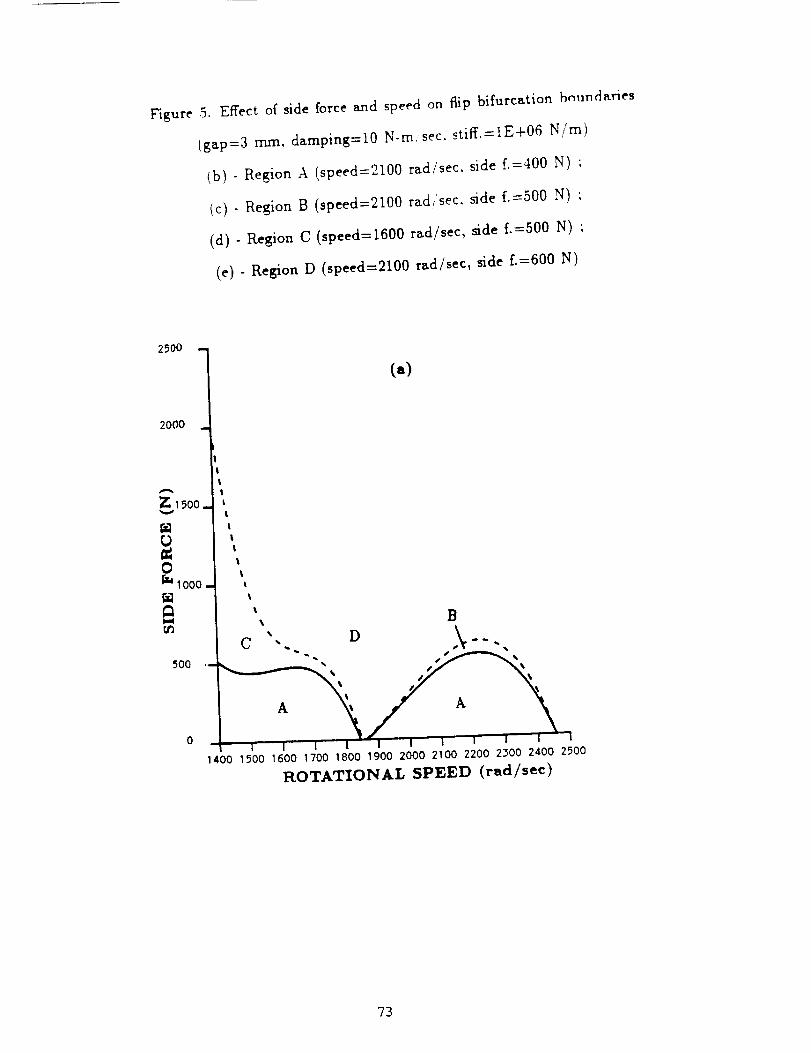
Figure 5. Effect of side force and speed on flip bifurcation bnundetries
(gap=3 ram, damping=10 N-re:see. stiff.=IE+06 N/m)
(b) - Region A (speed=2100 red�see, side f.=400 N) ;
(c) - Region B (speed=2100 red/see, side f.=500 N) ;
(d) - Region C (speed=1600 red�see, side f.-500 N) ;
(e) - Region D (speed=2100 red/see, side f.=600 N)
2500
2000m
Z;15oo_
rjgl0_IOOO =
5O0
IItI
I|
t
l
It
I
%C ,
(,,)
B
1400 1500 1600 1700 1800 1900 2000 2100 2200 2300 2400 2500
ROTATIONAL SPEED (tad/see)
73

0.00007
0°00005
0.0OOO3
0.00001
-.00001
-.00003
-.00005
(b)
I I I I ! i I I I
• 02988 .02990 .02992 .02996 .02998 .03002 .03004• 02994 .03000
Y
(=),
.0OOO65
.00_5
•000025
.0000C5
- .000015
- .000035
- .000055
.0298 .0299 .0200 .0301
Y
.0302
Figure 5, Contlnued
"74

(d) l
0.00005.
0.00003-
0.00001
-.00001
-. 00003
- • 00005
0.00014 J
.03004 .03006 • 03008 .0301 2 • 03014.03010
¥
(e)
.03018 .03020
,03016
0.00004
X
-.00006
.0298 .0299 .0300 .0301
Y
Figure 5, Continued
75

Figure 6. Flip bifurcationprocess with speed of 1600 rad/sec
(a) - primary stable whirling motion (side f.=450 N) ;
(b) - subsynchronous whirling motion _vith order 1/3 (side f.=500 N) ;
(c) - subsynchronous whirling motion _-ith order 1/9 (side £=527 N) ;
(d) - subsynchronous whirling motion with order 1/27 (side f.=535 N) ;
(e) - chtLotic whirling motion (side £=550 N) ;
(f) - power spectrum of chaotic motion (side f.=550 N)
(=)
O. 00010-
0.00005.
O. 00000'
-i00005'
-=00010,
-,,00015
0.00015.
0.00010,
0.00005,
.02935
y
(b)
.0298 .0299 .0300
Y
•0301 .0_02
76

O. 0001 5
0.00010
O. 00005
O. 00000
-.00005
-.DO010
-.DO015
0.00015 t0.00010
0.00005 1
0.00000
-.00005
-.00010
-.00015
.02980
I!
\• 0297 .0298
(c) t
.02990 .0300
Y
(d)
.0299 .0300
Y
.03010 .03020
•0301 .0302 .0303
Figure 6, Continued
77

0.00015
0.00010
0.00005
0.00000
-.00005
-.00010
i(e)
• 0296 .0297 .0298 .0299 .0300 .0301 .0302 .0503 .0304
Y
/,
(f)
L
2000
FKEQUENCY
Figure 6, Continued
78

Figure 7. Bifurcation plot due to side force
(gap=0.03 cm, damping 10 N-sec/m. stiff.=lE+06 N/m, speed=1600 rad/sec)
PI primary synchronous whirling motion
P3 subsynchronous whirling motion with order 1/3
P9 subsynchronous whirling motion with order 1/9
P1' secondary synchronous whirling motion
HBM(stable solution) ; .... HBM(unstable solution); o numerical integration
_J
NI
.OOO057
.O000B4- P1
400
o*I,F
I I ' I
SIDE FORCE (N)
79

Figure 8. Effect of side force and eccentricity on _p bifurcation boundaries
(speed=2100 rad/sec, gap=0.03 cm. dasuping=10 N-sec/m, stiff.=lE+06 N/m)
A pr/rna_ whirring ; B subsynchronous whirling ; C secondar7 whirring
520
500
C
B
420
A
4OO.0009 .0010 .0011 .0012 .0013 .0014
ECCENTRICITY (crn)
•0015
8O

Figure 9. Effect of side force and gap on flip bifurcation boundaries
(speed=2100 rad/sec, eccentricity=0.001 cm, damping=f0 N-sec/m, stiff.=IE+06 N/m)
A primar_ whirling ;B subsynchronous whirling ; C jecondar_ whirling
600"
55O
t._
0
u..
l,l
50O
4..50
400
_K_0
C
B
A
300
250
,022 .024 • 026 .028 .030 .032
GAP (cm)
.0_4
81

APPENDIX C
"A Convolution Approach for the Transient Analysis of Locally Nonlinear Rotor Systems,"
ASME Journal of Applied Mechanics, Vol. 57, pp. 731-737, 1990.
82

I. F. ChiangGraduateStudent.
S. T. NoahAssociateI_'ofessor.
Mern. ASME.
MechanicalEngineeringDepartment,Texas A&M University,
College Station,TX 77843
A ConvolutionApproachfor theTransientAnalysisof LocallyNonlinearRotorSystemsA computationally efficient convolution method, based on discretized impulse re-sponse and transition matrix integral formulations, is developed for the transient
analysis of complex linear structures interacting through strong local nonlinearities.
In the formulation, the coupling forces due to the nonlinearities are treated as external
forces acting on the coupled subsystems. Iteration is utilized to determine their
magnitudes at each time increment. The method is applied to a generic rotor-housing
model representing a turbopump of a space shuttle main engine ( SSME). In that
model, the local nonlinearity is due to clearances between the rotor bearing outer
races and the carrier attached to the housing. As compared to the fourth-order
Runge-Kutta numerical integration methods, the convolution approach proved moreefficient and robust for the same accuracy requirement. This is due to the closed-
form formulation of the convolution approach which allows for the use of relatively
larger time increments and for a reduction in the roundoff errors.
Introduction
The use of a direct numerical integration for determiningthe transient response of coupled nonlinear rotor-flexible hous-
ing systems may require excessive computational time and in-volve unacceptable computational roundoff errors. To remedythese problems, different procedures have been developed byanalysts to determine the transient response of large order rotorsystems. The procedures can be recognized as falling underone of two basic approaches: those using physical or modal
coordinates of the complete system and those using the co-ordinates of the individuals components of the system. Themethods also differ in the numerical integration methods se-lected for the analysis.
Rouch and Kao (1980) employed Guyan (static) reductionmethod to arrive at a reduced size model in terms of the re-maining physical coordinates. Accuracy of the results could
be expected to be acceptable, since the rotor is basically a trainof mass-stiffness subsystems. Nordmann (1975) attempted tominimize the inaccuracy of static condensation by applyingthe static reduction technique to an arbitrarily substructuredrotor system and then assembling the reduced substructures toform a reduced system. The procedure is very laborious and
no guarantees of accuracy axe apparent.
Contributed by the Applied Mechanics Division of Tl.ll_ A.gspJC.J_,_ SOC_en'
oF M_c_zc._ ENCn,_Zl.5 for presentation at the Winter Annual Meeting,Dallas, Texas. Nov. 25-30, 1990,
Discussion on this paper should be addressed to the Technical Editor, LeonM. Keer, The Technological Institute, Northwestern University, EvanSton, iL
60208, and will be accel_ed until two months after final publication of the Wiper
i[self in the Joupaoa. oF A.PPI._D MECRA>nCS. Manuscript received by the ASMEApplied Mechanics Division, Oct. 10, 1988; final revision. Sept. 27, 1989.
Paper No. 90-WA/APM-21.
Journal o! Applied Mechanics
Childs (1978) utilized free-interface modes of the varioussystem components to represent the assembled turbopumps ofa space shuttle main engine (SSME). The method, using fourth-order Runge-Kutta integration, does not allow for size reduc-tion of the housing model while maintaining sufficient modal
coordinates for accurate representation of the housing. Nelson
et al. (1982), on the other hand, uses fixed-interface complexcomponent modes to assemble a reduced size model. For sys-tems with a large number of coupling points among the com-ponents, the approach suffers from an introduction of higherfrequencies resulting from an excessive number of constraintsimposed at the coupling (or boundary) points, In a transientanalysis, this will necessitate employing much smaller timeincrements and consequently will lead to excessive computa-tional time.
Only a few analysts have presented techniques for the generaltransient analysis of large nonlinear rotor systems. Adams(1980) used a normal mode representation for the rotor interms of its undamped, free symmetric modes and treated
gyroscopic and nonlinear terms as pseudo-external loads. Themethod presented by Childs (1978) makes use of a similarprocedure to couple the rotor to its flexible housing. Nelson
et at. (1982) developed a general computer code for the tran-
sient analysis of large rotor systems. The user may utilize time-
step integration in the constrained-rotor (fixed-interface) modal
space. Again, all connection points, including those at thenonlinearities, must be constrained, leading to the same short-
comings described previously.Spanos et at. (1988) considered linear systems analyzed as
decoupled subsystems. The accelerations at the interface arepredicted at the beginning of each time step. The accelerationsof the interface and interior nodes are then calculated and
SEPTEMBER 1990, Vol. 57 / 731
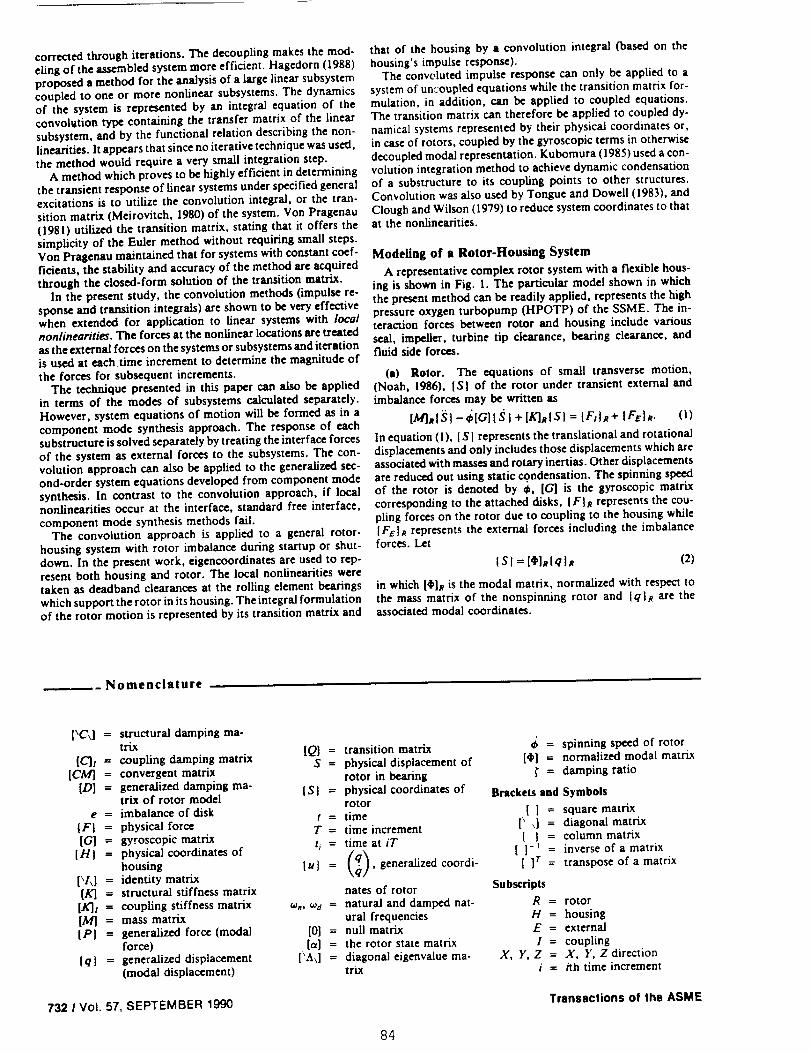
corrected through iterations. The decoupling makes the mod-
eling of the assembled system more efficient. Hagedorn (1988)proposed a method for the analysis of a large linear subsystemcoupled to one or more nonlinear subsystems. The dynamicsof the system is represented by an integral equation of theconvolution type containing the transfer matrix of the linear
subsystem, and by the functional relation describing the non-iinearities. It appears that since no iterative technique was used,the method would require a very small integration step.
A method which proves to be highly efficient in determiningthe transient response of linear systems under specified generalexcitations is to utilize the convolution integral, or the tran-
sition matrix (Meirovitch, 1980) of the system. Von Pragenau(1981) utilized the transition matrix, stating that it offers the
simplicity of the Euler method without requiring small steps.Von Pragenau maintained that for systems with constant coef-ficients, the stability and accuracy of the method are acquiredthrough the closed-form solution of the transition matrix.
In the present study, the convolution methods (impulse re-sponse and transition integrals) are shown to be very effective
when extended for application to linear systems with localnonlinearities. The forces at the nonlinear locations are treated
as the external forces on the systems or subsystems and iterationis used at each time increment to determine the magnitude ofthe forces for subsequent increments.
The technique presented in this paper can also be appliedin terms of the modes of subsystems calculated separately.
However, system equations of motion will be formed as in acomponent mode synthesis approach. The response of each
substructure is solved separately by treating the interface forcesof the system as external forces to the subsystems. The con-volution approach can also be applied to the generalized sec-
ond-order system equations developed from component mode
synthesis. In contrast to the convolution approach, if localnonlinearities occur at the interface, standard free interface,component mode synthesis methods fail.
The convolution approach is applied to a general rotor-housing system with rotor imbalance during startup or shut-
down. In the present work, eigencoordinates are used to rep-resent both housing and rotor. The local nonlinearities weretaken as deadband clearances at the roiling element bearingswhich support the rotor in its housing. The integral formulationof the rotor motion is represented by its transition matrix and
that of the housing by a convolution integral (based on thehousing's impulse response).
The convoluted impulse response can only be applied to a
system of uncoupled equations while the transition matrix for-
mulation, in addition, can be applied to coupled equations.
The transition matrix can therefore be applied to coupled dy-namical systems represented by their physical coordinates or,
in case of rotors, coupled by the gyroscopic terms in otherwise
decoupled modal representation. Kubomura (1985) used a con-volution integration method to achieve dynamic condensationof a substructure to its coupling points to other structures.Convolution was also used by Tongue and Dowell (1983), and
Ciough and Wilson (1979) to reduce system coordinates to thatat the nonlinearities.
Modeling of a Rotor-Housing System
A representative complex rotor system with a flexible hous-
ing is shown in Fig. I. The particular model shown in whichthe present method can be readily applied, represents the high
pressure oxygen turbopump (HPOTP) of the SSME. The in-
teraction forces between rotor and housing include various
seal, impeller, turbine tip clearance, bearing clearance, andfluid side forces.
Ca) Rotor. The equations of small transverse motion,
(Noah, 1986), [S] of the rotor under transient external and
imbalance forces may be written as
IM]slS}- OIG-'] I._ )+ IKI_IS} = IF/)R+ IF_]_. (I)
In equation (!)0 I S I represents the translational and rotational
displacements and only includes those displacements which are
associated with masses and rotary inertias. Other displacementsare reduced out using static condensation. The spinning speedof the rotor is denoted by _, [G] is the gyroscopic matrix
corresponding to the attached disks, IF}R represents the cou-pling forces on the rotor due to coupling to the housing while
IFE]_ represents the external forces including the imbalanceforces. Let
I SI = [¢]RIqIR (2)
in which [_]R is the modal matrix, normalized with respect to
the mass matrix of the nonspirming rotor and [q}R are theassociated modal coordinates.
Nomenclature
[\C\] = structural damping ma-trix
[Cb = coupling damping matrix [Q} =S=
[CA'/] = convergent matrix
[D] = generalized damping ma-trix of rotor model IS} =
e = imbalance of diskt =
{F} = physical force T =[G] = gyroscopic matrix
[H] = physical coordinates of t, =
housing I u } =
[x/x] = identity matrix
[K] = structural stiffness matrix
[K]/ = coupling stiffness matrix _., _d =
[M] = mass matrix{P] = generalized force (modal [0] =
force) [a] =
{ q ] = generalized displacement [_A\] =
(modal displacement)
transition matrix 6 = spinning speed of rotor
physical displacement of [¢I,] = normalized modal matrix
rotor in bearing _" = damping ratio
physical coordinates of Brackets and Symbolsrotortime [ ] = square matrixtime increment [\ \] = diagonal matrixtime at it [ ] = column matrix
, generalized coordi- [ = transpose of a matrix
nares of rotor Subscripts
natural and damped nat- R = rotorurai frequencies H = housing
null matrix E = external
the rotor state matrix I = couplingdiagonal eigenvalue ma- X, Y, Z = X, Y, Z directiontrix i = /th time increment
732 I Vol. 57, SEPTEMBER 1990 Transactions of the ASME
84
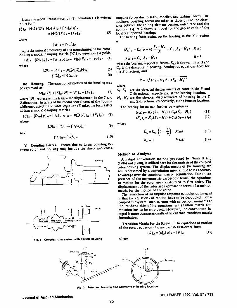
Using the modal transformation (2), equation (1) is writtenin the form
[_1_- [)]rd[G]_Icl']s[ d )R + ['A\]s( q ] s
= [4']r(lF_l R+ IFtl_) (3)
where
['Ad_ = [_,o.2dR.
,o, is the natural frequency of the nonspinning of the rotor.Adding a modal damping matrix [\C\] to equation (3) yields
{#]It+[D]RIqIR+[\A\]R[qlR=[_]T([F/}R+ IFEIR) (4)
where
[Db = ['C,l_- [_]r,_[61,d¢'lR (5)
['CJ_ = ['2/'_.d,_. (6)
(b) Housing. The equation of motion of the housing maybe expressed as
[MIMHI + [EI.IHI = [FIIH+ IF_lx C/)
where (HI represents the transverse displacement in the YandZ-directions. In terms of the modal coordinates of the housingwhile uncoupled to the rotor, equation (7) takes the form (afteradding a modal damping matrix)
[0IH+ [DIHI (I }H+ [_Ad.lqln = [4'I_(IF:IH+ [FEIH)
where
[D]H= ['CdH = [_2/'_.dn
iS)
(9)
and
[_A\].= P_.:JH. (10)
(c) Conpling Forees. Forces due to linear coupling be-tween rotor and housing may include the direct and cross-
turbines
• Fig. 1 Complex rotor syslem with |lexlb|s housing
coupling forces due to seals, impeller, and turbine forces. Thenonlinear coupling forces are taken as those due to the clear-ance between the rolling element bearing outer race and thehousing. Figure 2 shows a model for the gap at each of theloosely supported bearings.
The bearing force acting on the housing in the Y-directionis
Sr-Hr +Co(,_r-/'Ir) R_-6(Fc)r =KdR-(5) R
(FG) r=Ca( Sr- lClr) R <-6
where the bearing support stiffness, KG, is shown in Fig. 3 andCo is the damping in bearing. Analogous equations hold forthe Z-direction, and
R: %/ (Sr-Hr)2 + ($z-Hz) 2
where
St, Sz are the physical displacements of rotor in the Y andZ directions, respectively, at the bearing location.
Hr, Hz are the physical displacements of housing in the Yand Z directions, respectively, at the bearing location.
The bearing forces can further be written as
(Fo) r= Ko( Sr- Hr) + Co( S r-121r) (!1)
(Fc)z=l_o(Sz-l'lz)+Co(Sz-l;tz) (12)
where
](G---]¢O (l - _) R_'_ (13)
/_c=0 RSS. (14)
Method of Analysis
A hybrid convolution method proposed by Noah et al.,(1986) and (1988), is utilized here for the analysis of the coupledrotor-housing system. The displacements of the housing arebest represented by a convolution integral due to its accuracyadvantage over the transition matrix formulation. Due to thepresence of the unsymmetric gyroscopic terms, the equationsof motion for the rotor are transformed to first order. Thedisplacements of the rotor are expressed in terms of transitionmatrix for the motion of the rotor.
The restriction of an impulse response convolution integralis that the equations of motion have to be decoupled. For acoupled subsystem, such as rotor with gyroscopic moments atthe left-hand side of its equations, a transition matrix for-mulation has to be employed. However, the convolution in-tegral is more computationally efficient than transition matrixformulation.
Transition Matrix for the Rotor. The equations of motionof the rotor, equation (4), are cast in first-order form,
[ u }R= [a]R[ u ]R + [P}_ (15)
where
housing
Y
c_ _/_
Fig. 2
Z
Rotor and housing displacements el beadng location
housing
= y
Journal o! Applied Mechanics SEPTEMBER 1990, Vol. 57 I 733
85
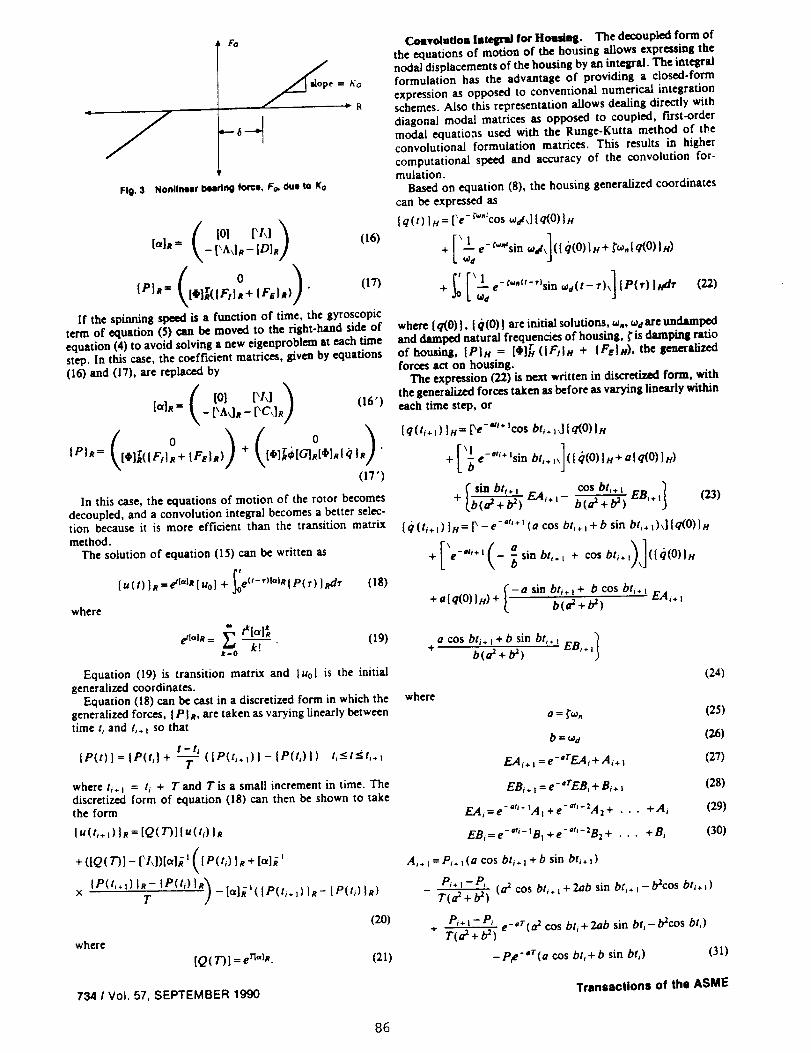
1to
= Ka
Fig. 3 Nonlinear beadng force, Fo, due to Ka
[0l [\i\)
\_ t'A,].-tD],] (16)
If the spinning speed isa function of time, the gyroscopic
term of equation (5) can be moved to the right-handsideof
equation (4)to avoid solvinga new eigenproblem at each time
step. In this case, the coefficient matrices, given by equations
06) and (17), are replaced by
{alR= - [\AdR - [\C\]R) (16')
( )( o )IPI_= [4qar({FH_+ {F_IR) + (_]T¢'{G]eI4'IR{qIs "
(17 ')
In this case, the equations of motion of the rotor becomesdecoupled, and a convolution integral becomes a better selec-tion because it is more efficient than the transition matrixmethod.
The solution of equation (15) can be written as
lu(t)}s=etI°l_{uo} + e('-')l_lRlP(r)lRdr (18)
where
k! (19)k=0
Equation (19) is transition matrix and luol is the initialgeneralized coordinates.
Equation (18) can be east in a discretized form in which the
generalized forces, I PIR. are taken as varying linearly betweentime t, and t,.) so that
t -- I i
{P(t) } = [P(t,] + "-7- ( [P(ti. t) ] - [P(t,)] ) t_<__t<t_÷ :
where t,÷ : = t_ + T and T is a small increment in time. Thediscretized form of equation (18) can then be shown to takethe form
I u(t,. ,) I_ = {Q( 731{u(t_) IR
+ ([Q(7)1 - ['Id)la]_'([P(t/) }R + [a]_ 'N
x {P(t,÷:)IR- {P(t_)l,_)T - 1'']'_ :( IP(ti. :) }R- IP(ti) }R)
(20)
where
[Q( 7")] = e rlabt. (21)
734 / Vol. 57, SEPTEMBER 1990
Coavolutlom Integral fo¢ Homtag. The decoupled form ofthe equations of motion of the housing allows expressing the
nodal displacements of the housing by an integral. The integralformulation has the advantage of providing a closed-formexpression as opposed to conventional numerical integration
schemes. Also this representation allows dealing directly with
diagonal modal matrices as opposed to coupled, first-ordermodal equatioas used with the Runge-Kutta method of the
convolutional formulation matrices. This results in highercomputational speed and accuracy of the convolution for-mulation.
Based on equation (8), the housing generalized coordinates
can be expressed as
{q (t)Is = [\e- r_":COS _¢.'_J {q(O) ]n
e- r_"sin _'¢_.I q(O) l t c)+['I -d,](l 0(0)}H+
+ _ ['le-"'-"sin.,(t-r),]{P(r)lsdr (22)
where (q(0)1, Iq(0)Iare initialsolutions,oJ.,¢o_areundamped
and damped naturalfrequenciesof housing, _'isdamping ratio
of housing, {Pln = [4']r ({F/In + {Faln). the generalized
forcesact on housing.
The expression(22)isnext writtenin discretizedform, with
the generalizedforcestaken as before as varying linearlywithin
each time step,or
( q(t/+ :) }H= [Xe-*'l+ :cos bti. z_] [q(0)}H
e -aq+ Isi n+['_ bli. l,]( [ *(O) ]H+ a' q(O) }H)
I sin bti" : c°s bti+ ' 1+ b(a=+b3) F_Ai+: b(oZ+b_) EBb.: (23)
I c/(t/. :) l_/= [X -e-"i_ : (a cos bt/. : + b sin bti+:)\llq(0)} H
[' (° 1]+ • -'ti÷l -- _sinbti. t + cosbti.: (Iq(0)} H\
+a(q(0)Jx)+ _-a sin bt/.)+ b cos bL÷= EA/.,b(a=+b_)L
a cos bt_.:+b sin bt,.: )+ b(a_+l_) EB,.,
where
(24)
a = _'w. (25)
b = _,# (26)
EA,. == e-'rEA, + Ai+ : (27)
EB, + : = e-=rEB_ + B,+ : (28)
EA/=e -_'/- :At +e-°"-:A_+ • • • +A, (29)
EBi = e- _i- _B: + e-*_'- 2B: + . . . + B_ (30)
A,. : = Pi. :(a cos bti. : + b sin bti ÷ : )
Pi + ! -- Pl
T(a_ + b_ ) (a _ cos bt,+ : + 2ab sin bti. : - b_cos bt,.. : )
P'*:-P_ e-°r(a _ cos bt_+ 2ab sin bt,-b_cos bt,)+ T(a_+b _)
-Pte-'r(a cos b6 + b sin bt_) (31)
Transactions of the ASME
86

B, . t = P+ . _( a sin bt, . i - b cos bt, . : )
P,,t-PiTfa2 + b2 ) (a 2 sin bt, . i - 2ab cos bt , + t -/_sin bt i. i)
P'+ _- P' e-°r ( a: sin bt,- 2ab cos bt,- b:sin bt,)+ T(a_+b :)
-P#-'r(a sin bt,- b cos bti) (32)
P is element of vector IPI.
The Coupling Forces. The coupling forces actingon the
housing are given by
{Ftln= [K]_({SI- {HI)+ [CD({._I- {HI) (33)
and those on the rotor axe
IF, I_= - IF:IH
where [K]: and [C]t axe the coupling stiffness and dampingmatrices, respectively. The coupling stiffness matrix includes
the updated bilinear bearing stiffness at each iteration.
The Computational Procedure. For the responses at time
t = t,÷ i, the coupling forces between the housing and rotoraxe unknown. An iterative technique is used to calculate these
forces. The following iterative loop is used in both the hybrid
and Runge-Kutta methods:
If the responses at t = t_ axe known and responses at t = t,.
are desired, then:(a) Set IFt(t+÷0} = IFi(t_)}.
Co) Calculate IPIR and I Pin-
(c) Solve lu(ti+l)lRand Iq(t+÷l)ln, Iq(t,÷t)lHbythehy-
brid method (or the Runge-Kutta method). Calculate the Eu-
clidean norm of {u(ti÷l)lR and Iq(t_+t)ln.
(d) Transfer lu(h+Dl# and Iq(ti+Dl#, Iq(t,÷+)ln back
to physical coordinates, then a new connection force {F_(t+÷ t) }can be calculated.
(e) If the Euclidean norms of two consecutive iterations
of both rotor and housing are close enough then stop the
iteration and go to step It'), otherwise go to Co).
(f) Move a time increment and go to (a) until t reaches aspecified time for terminating the run.
The Convergence of Hybrid Method. Rewrite the couplingforces as the function of the generalized coordinates, equations(20), (23), and (24) can be arranged as the following form:
_(k)\
/u(t,+l, _ (u(t,.l)'i-l"_
/od,2,;'*'? : tct<× /o.2;;"-"/ +l l (34)Xq (t,÷,)'*'/ kq (t,÷,)'*-'V
where k stands for kth iteration at a given time t,. _, [CM] is
the convergent matrix (Isaacson and Keller, 1966), I cl is vectorwith known values, and
([Sl} [$2}_ (35)
[C/V/q= _[S31 IS4]/where
(0 0)[Sll = In} x - [¢>I_[RI_{¢IR- [¢ir{cb{OlR
(o o)1S21= In} x [OlrlK]t[Oln[OlrlCb[Ol
Joumal of Applied Mechanics
R7
[{r2114,l_{ghl_IR[r'2ll_lrlC]:l_lR'_
tsm:
/'-tn]t+gama+b, -tnlt+++tcja+]. is41=and
( ,°,,+')[rl]= [c+l_' (IQ(7")I- 1'1,1)--_ - ['1\1
[\ sin bt,+t AC cos bt+., AS,][_1 = t,(a_ + M) _(aa+M)
\ -a sin bti+ _+b cos bt_+_[731= b(_+_) AC
acos bti+ t + b sin bt,+ _ ]+ AS,
where
AC=a cos bt,+ _+b sin bti+_
1
- T(az+l_) (a_ cos bt++_+2ab sin bt_+_- b_cos bt,+_)
e-aT
+ T(aZ+b_) (a _ cos bti+2ab sin bti-b_cos bt_)
AS = a sin bt,+ _ - b cos bt_+
1
T(a_ + _) (a_ sin bt,÷_- 2ab cos bt,÷_- b_sinbt,+_)
_-oT
(a_ sin bt_-2ab cos bt_-_sin bt_).+ T(d+b_)
Equation (34) is in the form of the Jacobi iterative method
(simultaneous iterations),see (Isaacsonand Keller,1966).The
convergent matrix, [CM] may not be fixed at a given time
t= t,._as in an ordinary linearsystem because matrix [K]zmay
change during the iteration if the switch between two slopeareas in Fig. 3 exists.[Kitwillbe updated because the nonlinear
bearing stiffness, KG, changes. In this ease, there are two con-vergence rates during the iteration at that given time.
Equation (34) will converge if and only if all eigenvalues of[CA4] are less than one in absolute value. An alternative wayto check the convergence is that the iterative method will con-
verge if, for any matrix norm (Euclidean, maximum, etc.),I[CM]l < 1. Uncommon c&ses occur where convergence cri-
teria are met within one region in Fig. 3 and not the other. Inthat case, overall convergence at a given time t,. t might occurdepending on the pattern of movement from one region to theother. In any case, the convergence rate and size of the incre-
ment T will determine the outcome for acceptable accuracy.The rate of convergence, CR, is defined as the following:
CR - - log o([CMI)
where # ([CMI) isthe spectralradius of [CM] defined by
o([CM]) - max I hi I
where X+ are the eigenvalues of [CM].Let the initial error be defined as the norm of the vector of
the difference between the exact solution and an initial guess
at the beginning of iteration. The number of iterations, v,required to reduce the initial error by the factor 10 -m is in-
versely proportional to CR and is defined as
nlv_ _.
CR
SEPTEMBER 1990, Vol. 57 I 735

ROTOR: Sh_t _smete¢:. OD = T.26 × 10-1m, [D = 0.0m
MLteri_: E ffi2.0_84 x 10:*N/m:
Jc4nt k.Dgtl,= 7.26 × 10-:m
Rotor lentq, h,. 6,8,58 x 10-tin
HOUSING: Hnuins./rotot weilb t rMio = 6/l
(El)x- 8.6947 × l_Nm'
(ET)H= 1.7494 x 10'iNn@
F,(t) = ,,*,e_:co,_t Kss,= 7.oOsx tO'N/m Cc =o.o.¢'3(t) = m,e@_d_ Kill = 8.7563 x lO¢Y/m
F,(i) = rn_(@Ico,@( KS;,',* 8.7563 x ]0'Ar/m
F,(|) = m=e41nnjl Ksy,= 2.6289 x 10'N/m
¥*(0 = ms_¢ _' A'_ = S.;S63 x IO'N/_F.(0 - [email protected]#,t # _ 0.0127mm
F_.4 W,e gem,re mo_
Application and Discussion
The present convolution method is appfied to a modifiedversion of a rotor model proposed by Davis et al. (1984). The
model was proposed to represent a simplified generic model
of the SSME turbopumps. The parameters and coefficients ofthe present generic model (shown in Fig. 4) are given in Tables1 and 2. The imbalance forces are taken as shown on Fig. 4.
Response of the generic rotor-housing model at the bearinglocation is determined for the hypothetical startup-shutdown
case shown in Fig.5. For various time increments, At, a corn.parison ismade of the errors and computer CPU time (on aVAX 8650) between the resultsobtained using Runge-Kutta
fourth-order method and those using the presentconvolutionmethod.
Comparisons of the CPU time,are made with comparable
errors of the resultsof using both methods. The errors is
measured attime t = 0.01seconds and definedas the following
Error - I V=- V!IV==I
where V¢_ isthe exact solution of the rotor and housing dis-placements in vector form and V representsthe displacements
of rotor and housing atthe corresponding time invector form.
The "exact" solution is calculated using the hybrid con-volution method with a very small time increment, 2 x 10⁻⁷seconds and tolerance = I x I0-_2. The tolerance is the
absolute value of the differenceof the displacement and ve-locitynorms of rotor and housing describedin step(e)of the
computational procedure.
As shown in Figs.6 and 7, with the toleranceequals to l
× I0-_ seconds, the hybrid convolution method isfasterand
more accurate.For more meaningful comparison, the accur-
aciesof the Runge-Kutta and convolution methods are made
closerby reducing the allowabletolerancefor the Runge-Kuttato I x I0- _ seconds and I x I0- ,4seconds. The CPU time
for the Runge-Kutta increasesquickly from 1.42times of the
736 / Vol. 57, SEPTEMBER 1990
T_ _ paran_un o! the ¢enedc mode4
[_,k (K_) I ('')
-1 °- i9.0175 O.O_IM
Moment d inertia (Kt.m_)
Polu Di_m_tricLl
3.1635x I0-_ 1.7964x 10-s2.1806x I0-] 1.1411x I0-_1.1363 x I0 -_ 5.7373 x 10 -_
TaMe 2 CoMtlkllents of the genetic mockd
] Kyy, A'zz Kxy, h'_'x Cvr, Cz_
(N/,_) (N/m) (Jr ,ec/m)Disk
1 1.7513 x 10_ 2.6269 x 10'2 -1.5566 x 10_ -7.0050 x l0 s3 1.5236 x 10e 3.3274 × 10s
1.1033x I041.7513x I0_
4.0279x I0:
I)bk
I
2
3
Sideforce(N)
Y-direction Z-direction
2.2019 × 10⁴ q_ -1.2482 × 10⁻⁴ _2.7210 x 10-4 _ 3.2387 x 10⁻⁴ ¢_
1.0_82 x 10-4 _ 0
,_ (r_/sec)
;
4001
0.3 0.6 0.9
Fig. 6 Running speed of rolo_
Time (see)
hybrid method's CPU to 4.23 times (with a time increment of2 x 10-s).For the closestaccuracies,the CPU time of the
Runge-Kutta is 4.23 times that of the hybrid method. The
hybrid convolutionmethod isalsomore robust than the Runge-
Kutta method. The Runge-Kutta algorithm failedto convergefor time increments greaterthan 2 × I0-_ seconds. However,
the hybrid method win diverge when the increment used islargerthan 3.3 × I0 -s seconds.
Concluding Remarks
The convolution integral and transition matrix methods are
represented in closed form. They generate less roundoff errorsand require less numerical computation time in comparisonwith the Runge-Kutta fourth-order method. Moreover, theyare more robust than the Runge-Kutta method since they willconverge for larger time-step size.
The hybrid convolution approach developed in this study isshown to provide an efficient and accurate closed-form integral
formulation for determining the transient response of linear
systems coupled through local nonlinearities. A typical appli-cation in which the present method proved quite effective isthe determination of the wansient response of a generic model
of the high pressure oxygen turbopump (HPOTP) of a spaceshuttlemain engine (SSME) inpresence of bearing clearances,
constitutingthe local nonlinearities.Substantial savings in
computation time were achieved as compared with directnu-
merical integrationtechniques.The use of the transitionmatrix allows the representation
of rotors involving skew-symmetric matrices of gyroscopic
loads or other nonconservative systems with general velocity
coefficientmatrices.A convolution integralwould represent
quiteeffectivelyother systems with classicalmodes, such as
Transactions of the ASME
88

0 7
0.!0.5
°' 7
I'_ 0.3-
0.2
0.1
0.0
0.0
Fig. 8
40O
LEGEND
+ HYEIRID (TOL-I.E-8)
--4" RUNG[ KuTTA CTOL-UE-8)
-t- RUNG[ KUTTA (TOLwl.E-12)
-,_- RUNG[ KUTTA (TOL-LE-14)
//
/
[ i i _ i
0.5 1,0 1.5 2.0 2.5
TIME STEP SIZE (X 10000 SECOND)
Accurecy ot by'odd method end Runoo-Kutts methods
t3.0
Z00
200-
:Da.tO
I00-
LEGEND
"-0- _ CroL.-LE-8)-4,- RUNG[ gurvA CrCX..-_.E-8)-_1 .o RUNG[ KUTTA (TOt--I,[-12)
--O'- I_NGE KUTTA ('1"Or.-1.[-14)\
\
\
4k _'-
"- "h3.._
I 2 3
TiME STEP SIZE (X 10000 SECOND)
FiO. 7 CPU time of hylxld method end Run_Kuttx mtho_
the housing of the HPOTP or other nonrotating, proportion.
ally damped structures. The convolution formulation allows
accommodating with ease changes in the nonlinear or linear
coupling parameters among the various linear subsystems in-
volved.
Possible improvement of the method could be achieved
through other alternative or optimization for the iteration pro-
cedure utilized in this study. The methods described in this
study is believed to be capable of handling any type of local
nonlinearity. For an impact case at the bearing, for example,
iteration over the contact force could be replaced by iteration
to establish contact/no-contact at each increment and then
reverse the impact velocity. Applications of the present method
to systems with various types of local nonlinearities could be
worthwhile.
AcknowledgmentThis work was carried out as part of a research project
supported by NASA, Marshall Flight Center, under contract
No. NAS8-36293. The authors are grateful to Thomas Fox,
the technical monitor, for his enthusiastic support and interest.
ReferencesAdams, M. L., 19110, "Non-linear Dynamtcs of Flexible Mudti-Beatgn8 Re-
lots," Journal of Sound and Yibralion, VOl. 7], I>P. 129-144.Chikh, D. W., 1978, "The Space Shuttle Main F._ High Pressure Fuel
Tur_p-Rmordymunic InstabilityProbtma," A,._MEJowrnalofEnfi_
for Power, VOl. 100,pp, 48-$I.
Clough,R, W., and Wilson,E. L., 1979,"DTnamic _ of Larle $tr_c-ruralSystemsWith Local Nonlimmritics,"Comlmtee Medmds in_ Me-
clumKa_F.ngi_, Vet. 17 18, pp. 107-129.Davis, L. B., Wolfe, E. A., and Bentty, R. F., 1984. "Housing Flem'bility
Effects on go¢or Stability," MSFC Advanced Hilh Pressure O2/H2 Technoio_Omfmmee Proce_lir_, G. Mantbxll Space Flight Center, H_, Ale.Haledom, P., Sdmman, W., 1918, "On the Dynamics of Larle Slmems
With Localized_," ASME Jota_uo.or _ M_, Vol.
55,PP. 946-951,
lw_son, E., and Ig.¢_, H, B., 1966, Aawl,v'_J of Numeefeal Methods, JohnWiley tnd Sons,New York.
Kubomurt, K., 198L "Trsmi_t Loads Anaiy_s by Dynamic CondemaUion,"
ASME Jotn_u. oF _ _cs, Vol. 52, pp. 559-_4.M¢irovitch, L., 1980, Computational Methods m Slructural Dynamics, Sijth-
off and Noordhoff.
NdJo_, H. D., Mendmm, W. L., Fleming, D. P., and KJ.scak, A. F., 1982,"Nordinenr AnAlySiS of Ro¢or Bearing Systems Using Component Mode Syn.thesis, ASME Paper No. 82-GT-303.
Noah, S. T., 1986, "Hybrid Methods for Ro¢ofdymunic An_ysis," Fina/NASA Report, G. C. Marshall Space Flight Center, Ala., under Contrac'_ No.NAS_36182, Dec. 1956.
Noah, S. T., Cbia_, !. F., and Kim, Y. B., 1988, "Dynam_ Antlym ofNonlinear Romr/Homi_ Systems," MSFC Advanced High Pressure O._HaT=hnolou Confe*en= Proceedials, G. Marshall Space Flilht Center, Hunu-vilk, Ale.
Noah, S. T., Fan, U. J., C'boL Y.-S., and Fox, T., 1986, "Efficient TransientAmdysb Methods for the Space Shuttle Main Enl_ne Turbopumps," NASAConference on Advanced Earth-to-Orbits Propulsion Tcch., G. Marshall Slmc¢Fillet C.em_r, Huntsville, Ale., May 1]--15.
Nordmxna, R., 1975. "EilK'nvalu_ and R_onan_ Frequency Forms of Tur-Ix)rotors with Sleeve Bearings Crank Excitation, External, and Internal Damp-ing," Ma_hln¢ Dymunics Group, Technical Ul_y_ly DiJ'mlRJIdz, F.R.G.
gouch, K. E., end Kao, J. $., 19@0, "Dynamic Reduction m Ro¢or Dynamicsby the Finite Element Method," ASME Jo_u4._u.oF MEcm_,mc_k D_ao_, Vol.102, pp. 360-368.
Spoor, P. D., C.ao, T. T., Janoblon, C. A., Jr., and Nelson, D. A. R., Jr.,1988, "De¢oupled D_ Al_]ysis of Combined Systems by herative Deter-ruination of Interface Ao:_'ka'tfions," Earthquake En_u,g,enng and StructuralDynamics, Vol. 16, pp. 491-500.
Tongue, B. H., and Do,ell,E. H., 1983, "Component Mode Analysis ofNoa/inear, Nonconse_rative Syaems," ASME lOtrtJ_L oe AeeLmo M_cm*.mcs,Vol. 50, pp. 204--209.
Yon Prqeaan, G. L., 1951, "Larl_eStep Integration for Linear DynamicSystems," Conference Proc, IEEE Southen_ern '81, reprint Apr,
Journal of Applied Mechanics
89
SEPTEMBER 1990, Vol. 57/737

Report Documentation Page
1. Report No. 2. Government Accession No.
4. Title and Subtitle
Nonlinear Rotordynamics Analysis
7. Author(s)
Sherif T. Noah
9. Performing Organization Name and Address
_rshall Space Flight Center
Alabama 35812
12. Sponsoring Agency Name and Address
National Aeronautics & Space Administration
Washington, DC 20546-0001
3. Recipient's Catalog No.
5. Report Date
February, 1991
6 Performing Organization Code
8. Performing Organization Report No
10. Work Unit No.
11. Contract or Grant No,
NAS8-37465
13. Type of Report and Period Covered
Final
14. Sponsoring Agency Code
15. Supplementary Notes
16. Abstract
Effective analysis tools have been developed for predicting the nonlinear rotor-
dynamic behavior of the SSM_ turbopumps under steady and transient operating condi-
tions. Using these methods, preliminary parametric studies have been conducted on
both generic and actual HPOTP (high pressure oxygen turbopumps) models. In particul_
a novel modified harmonic balance/alternating Fourier transform (HB/AFT) method was
developed and used to conduct a preliminary study of the effects of fluid, bearing
and seal forces on the unbalanced response of a Multi-disk rotor in presence of
bearing clearances. A computer program was developed and made available to NASA,
Marshall. The method makes it possible to determine periodic, sub-, super-synchro-
nous and chaotic responses of a rotor syst_n. The method also yields information
about the stability of the obtained response, thus allowing bifurcation analyses.
This provides a more effective capability for predicting the response under transienl
conditions by searching in proximity of resonance peaks. Preliminary results were
also obtained for the nonlinear transient response of an actual HPOTP model using an
efficient, newly developed numerical method.based on convolution __t_ration=. _A
computer program was developed and made avallab, le .r_.ONASA Marsr_l.£ _±lgn_ Lsen_er.Cur_ the HB/AFT is belng extended for oeternurs_g _ne aperlcxllc response oz
17. Key Words (Suggested by Author(s))no_ sy_ 18. Oistdbution Statement
Initial results shows the method to be pra &sing.
19. Security Classif. (of this report) 20. Security Classff. (of this page)
21. No. of pages [22.
Price
.*f
NASA FORM 162:6 OCT 86