Embed Size (px)
Citation preview
333428GEN
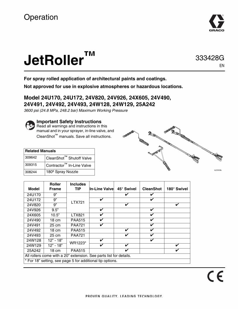
Operation
JetRoller™
For spray rolled application of architectural paints and coatings.
Not approved for use in explosive atmospheres or hazardous locations.
Model 24U170, 24U172, 24V820, 24V926, 24X605, 24V490, 24V491, 24V492, 24V493, 24W128, 24W129, 25A2423600 psi (24.8 MPa, 248.2 bar) Maximum Working Pressure
Important Safety InstructionsRead all warnings and instructions in this manual and in your sprayer, in-line valve, and CleanShot™ manuals. Save all instructions.
Related Manuals309642 CleanShot™ Shutoff Valve
309315 Contractor™ In-Line Valve
308244 180º Spray Nozzle
ModelRoller Frame
IncludesTIP In-Line Valve 45° Swivel CleanShot 180° Swivel
24U170 9”
LTX721
24U172 9”
24V820 9”
24V926 9.5”
24X605 10.5” LTX821
24V490 18 cm PAA515
24V491 25 cm PAA721
24V492 18 cm PAA515
24V493 25 cm PAA721
24W128 12” - 18”WR1223*
24W129 12” - 18”
25A242 18 cm PAA515
All rollers come with a 20” extension. See parts list for details. * For 18” setting, see page 5 for additional tip options.
ti23593b
Warnings
2 333428G
WarningsThe following warnings are for the setup, use, grounding, maintenance, and repair of this equipment. The exclamation point sym-bol alerts you to a general warning and the hazard symbols refer to procedure-specific risks. When these symbols appear in the body of this manual or on warning labels, refer back to these Warnings. Product-specific hazard symbols and warnings not cov-ered in this section may appear throughout the body of this manual where applicable.
DANGER6
ELECTROCUTION HAZARD To avoid death or serious injury, avoid contact with power lines.
WARNINGWARNINGWARNINGWARNINGFIRE AND EXPLOSION HAZARD Flammable fumes, such as solvent and paint fumes, in work area can ignite or explode. To help prevent fire and explosion:• Use equipment only in well ventilated area.• Eliminate all ignition sources; such as pilot lights, cigarettes, portable electric lamps, and plastic drop cloths
(potential static arc). • Keep work area free of debris, including solvent, rags and gasoline.• Do not plug or unplug power cords, or turn power or light switches on or off when flammable fumes are present.• Ground all equipment in the work area. See Grounding instructions.• Use only grounded hoses.• Hold gun firmly to side of grounded pail when triggering into pail. Do not use pail liners unless they are anti-static
or conductive.• Stop operation immediately if static sparking occurs or you feel a shock. Do not use equipment until you iden-
tify and correct the problem.• Keep a working fire extinguisher in the work area.
SKIN INJECTION HAZARD High-pressure spray is able to inject toxins into the body and cause serious bodily injury. In the event that injection occurs, get immediate surgical treatment.• Do not aim the gun at, or spray any person or animal.• Keep hands and other body parts away from the discharge. For example, do not try to stop leaks with any part of
the body.• Always use the nozzle tip guard. Do not spray without nozzle tip guard in place.• Use Graco nozzle tips.• Use caution when cleaning and changing nozzle tips. In the case where the nozzle tip clogs while spraying, fol-
low the Pressure Relief Procedure for turning off the unit and relieving the pressure before removing the nozzle tip to clean.
• Do not leave the unit energized or under pressure while unattended. When the unit is not in use, turn off the unit and follow the Pressure Relief Procedure for turning off the unit.
• Check hoses and parts for signs of damage. Replace any damaged hoses or parts.• This system is capable of producing 3600 psi. Use Graco replacement parts or accessories that are rated a min-
imum of 3600 psi.• Always engage the trigger lock when not spraying. Verify the trigger lock is functioning properly.• Verify that all connections are secure before operating the unit.• Know how to stop the unit and bleed pressure quickly. Be thoroughly familiar with the controls.
Setup
333428G 3
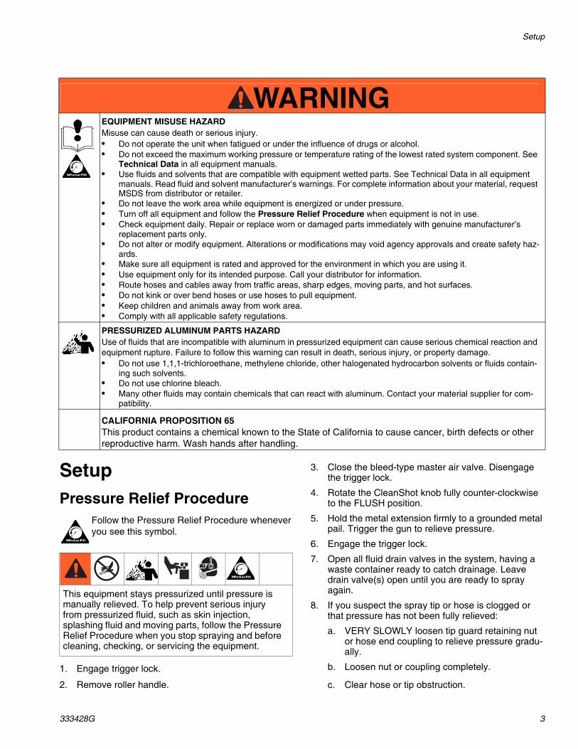
SetupPressure Relief Procedure
Follow the Pressure Relief Procedure whenever you see this symbol.
1. Engage trigger lock.
2. Remove roller handle.
3. Close the bleed-type master air valve. Disengage the trigger lock.
4. Rotate the CleanShot knob fully counter-clockwise to the FLUSH position.
5. Hold the metal extension firmly to a grounded metal pail. Trigger the gun to relieve pressure.
6. Engage the trigger lock.
7. Open all fluid drain valves in the system, having a waste container ready to catch drainage. Leave drain valve(s) open until you are ready to spray again.
8. If you suspect the spray tip or hose is clogged or that pressure has not been fully relieved:
a. VERY SLOWLY loosen tip guard retaining nut or hose end coupling to relieve pressure gradu-ally.
b. Loosen nut or coupling completely.
c. Clear hose or tip obstruction.
EQUIPMENT MISUSE HAZARDMisuse can cause death or serious injury.• Do not operate the unit when fatigued or under the influence of drugs or alcohol.• Do not exceed the maximum working pressure or temperature rating of the lowest rated system component. See
Technical Data in all equipment manuals.• Use fluids and solvents that are compatible with equipment wetted parts. See Technical Data in all equipment
manuals. Read fluid and solvent manufacturer’s warnings. For complete information about your material, request MSDS from distributor or retailer.
• Do not leave the work area while equipment is energized or under pressure. • Turn off all equipment and follow the Pressure Relief Procedure when equipment is not in use.• Check equipment daily. Repair or replace worn or damaged parts immediately with genuine manufacturer’s
replacement parts only.• Do not alter or modify equipment. Alterations or modifications may void agency approvals and create safety haz-
ards.• Make sure all equipment is rated and approved for the environment in which you are using it.• Use equipment only for its intended purpose. Call your distributor for information.• Route hoses and cables away from traffic areas, sharp edges, moving parts, and hot surfaces.• Do not kink or over bend hoses or use hoses to pull equipment.• Keep children and animals away from work area.• Comply with all applicable safety regulations.
PRESSURIZED ALUMINUM PARTS HAZARDUse of fluids that are incompatible with aluminum in pressurized equipment can cause serious chemical reaction and equipment rupture. Failure to follow this warning can result in death, serious injury, or property damage.• Do not use 1,1,1-trichloroethane, methylene chloride, other halogenated hydrocarbon solvents or fluids contain-
ing such solvents.• Do not use chlorine bleach.• Many other fluids may contain chemicals that can react with aluminum. Contact your material supplier for com-
patibility.
CALIFORNIA PROPOSITION 65 This product contains a chemical known to the State of California to cause cancer, birth defects or other reproductive harm. Wash hands after handling.
WARNINGWARNINGWARNINGWARNING
This equipment stays pressurized until pressure is manually relieved. To help prevent serious injury from pressurized fluid, such as skin injection, splashing fluid and moving parts, follow the Pressure Relief Procedure when you stop spraying and before cleaning, checking, or servicing the equipment.
Setup
4 333428G
ti23592a
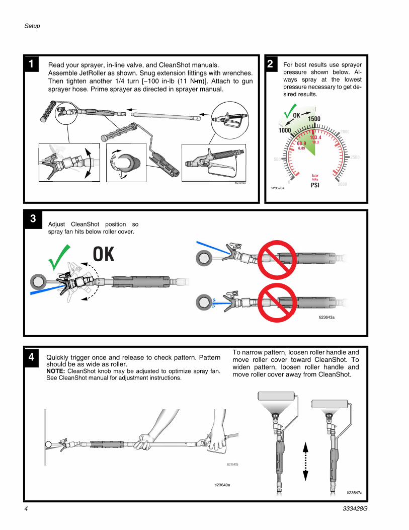
1 Read your sprayer, in-line valve, and CleanShot manuals. Assemble JetRoller as shown. Snug extension fittings with wrenches.Then tighten another 1/4 turn [~100 in-lb (11 N•m)]. Attach to gunsprayer hose. Prime sprayer as directed in sprayer manual.
500
2000
2500
30000
500
2000
2500
30000barMPa
1000
OK
PSI
68.96.89
103.410.3
1500
2 For best results use sprayerpressure shown below. Al-ways spray at the lowestpressure necessary to get de-sired results.
ti23598a
OK
Adjust CleanShot position sospray fan hits below roller cover.
ti23643a
ti23640b
Quickly trigger once and release to check pattern. Patternshould be as wide as roller. NOTE: CleanShot knob may be adjusted to optimize spray fan.See CleanShot manual for adjustment instructions.
To narrow pattern, loosen roller handle andmove roller cover toward CleanShot. Towiden pattern, loosen roller handle andmove roller cover away from CleanShot.
ti23640a
ti23647a
3
4
Setup
333428G 5
50%
12-24"ti23630b
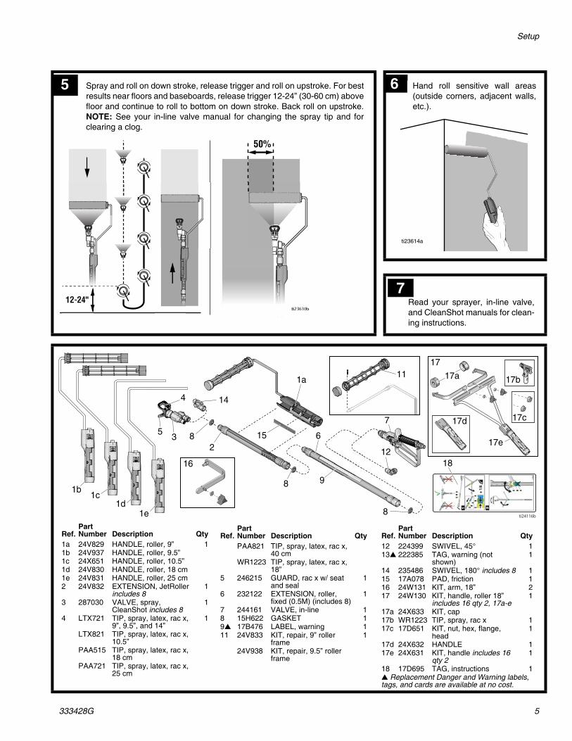
Spray and roll on down stroke, release trigger and roll on upstroke. For bestresults near floors and baseboards, release trigger 12-24” (30-60 cm) abovefloor and continue to roll to bottom on down stroke. Back roll on upstroke.NOTE: See your in-line valve manual for changing the spray tip and forclearing a clog.
5 Hand roll sensitive wall areas(outside corners, adjacent walls,etc.).
6
ti23614a
1a
1b
15
11
23
144
5 6
8
16
8
8
18
9
12
7
17
17a 17b
17c17d
17e
ti24116b
1c1d
1e
Ref.Part Number Description Qty
12 224399 SWIVEL, 45° 113 222385 TAG, warning (not
shown)1
14 235486 SWIVEL, 180° includes 8 115 17A078 PAD, friction 116 24W131 KIT, arm, 18” 217 24W130 KIT, handle, roller 18”
includes 16 qty 2, 17a-e1
17a 24X633 KIT, cap17b WR1223 TIP, spray, rac x 117c 17D651 KIT, nut, hex, flange,
head1
17d 24X632 HANDLE 117e 24X631 KIT, handle includes 16
qty 21
18 17D695 TAG, instructions 1 Replacement Danger and Warning labels, tags, and cards are available at no cost.
Ref.Part Number Description Qty
1a 24V829 HANDLE, roller, 9” 11b 24V937 HANDLE, roller, 9.5”1c 24X651 HANDLE, roller, 10.5”1d 24V830 HANDLE, roller, 18 cm1e 24V831 HANDLE, roller, 25 cm2 24V832 EXTENSION, JetRoller
includes 81
3 287030 VALVE, spray, CleanShot includes 8
1
4 LTX721 TIP, spray, latex, rac x, 9”, 9.5”, and 14”
1
LTX821 TIP, spray, latex, rac x, 10.5”
PAA515 TIP, spray, latex, rac x, 18 cm
PAA721 TIP, spray, latex, rac x, 25 cm
Ref.Part Number Description QtyPAA821 TIP, spray, latex, rac x,
40 cmWR1223 TIP, spray, latex, rac x,
18”5 246215 GUARD, rac x w/ seat
and seal1
6 232122 EXTENSION, roller, fixed (0.5M) (includes 8)
1
7 244161 VALVE, in-line 18 15H622 GASKET 19 17B476 LABEL, warning 111 24V833 KIT, repair, 9” roller
frame1
24V938 KIT, repair, 9.5” roller frame
Read your sprayer, in-line valve,and CleanShot manuals for clean-ing instructions.
7
All written and visual data contained in this document reflects the latest product information available at the time of publication. Graco reserves the right to make changes at any time without notice.
Original instructions. This manual contains English. MM 333428Graco Headquarters: Minneapolis
International Offices: Belgium, China, Japan, Korea
GRACO INC. AND SUBSIDIARIES • P.O. BOX 1441 • MINNEAPOLIS MN 55440-1441 • USA
Copyright 2014, Graco Inc. All Graco manufacturing locations are registered to ISO 9001.www.graco.com
Revision G, August 2017
Graco Standard WarrantyGraco warrants all equipment referenced in this document which is manufactured by Graco and bearing its name to be free from defects in material and workmanship on the date of sale to the original purchaser for use. With the exception of any special, extended, or limited warranty published by Graco, Graco will, for a period of twelve months from the date of sale, repair or replace any part of the equipment determined by Graco to be defective. This warranty applies only when the equipment is installed, operated and maintained in accordance with Graco’s written recommendations.
This warranty does not cover, and Graco shall not be liable for general wear and tear, or any malfunction, damage or wear caused by faulty installation, misapplication, abrasion, corrosion, inadequate or improper maintenance, negligence, accident, tampering, or substitution of non-Graco component parts. Nor shall Graco be liable for malfunction, damage or wear caused by the incompatibility of Graco equipment with structures, accessories, equipment or materials not supplied by Graco, or the improper design, manufacture, installation, operation or maintenance of structures, accessories, equipment or materials not supplied by Graco.
This warranty is conditioned upon the prepaid return of the equipment claimed to be defective to an authorized Graco distributor for verification of the claimed defect. If the claimed defect is verified, Graco will repair or replace free of charge any defective parts. The equipment will be returned to the original purchaser transportation prepaid. If inspection of the equipment does not disclose any defect in material or workmanship, repairs will be made at a reasonable charge, which charges may include the costs of parts, labor, and transportation.
THIS WARRANTY IS EXCLUSIVE, AND IS IN LIEU OF ANY OTHER WARRANTIES, EXPRESS OR IMPLIED, INCLUDING BUT NOT LIMITED TO WARRANTY OF MERCHANTABILITY OR WARRANTY OF FITNESS FOR A PARTICULAR PURPOSE.
Graco’s sole obligation and buyer’s sole remedy for any breach of warranty shall be as set forth above. The buyer agrees that no other remedy (including, but not limited to, incidental or consequential damages for lost profits, lost sales, injury to person or property, or any other incidental or consequential loss) shall be available. Any action for breach of warranty must be brought within two (2) years of the date of sale.
GRACO MAKES NO WARRANTY, AND DISCLAIMS ALL IMPLIED WARRANTIES OF MERCHANTABILITY AND FITNESS FOR A PARTICULAR PURPOSE, IN CONNECTION WITH ACCESSORIES, EQUIPMENT, MATERIALS OR COMPONENTS SOLD BUT NOT MANUFACTURED BY GRACO. These items sold, but not manufactured by Graco (such as electric motors, switches, hose, etc.), are subject to the warranty, if any, of their manufacturer. Graco will provide purchaser with reasonable assistance in making any claim for breach of these warranties.
In no event will Graco be liable for indirect, incidental, special or consequential damages resulting from Graco supplying equipment hereunder, or the furnishing, performance, or use of any products or other goods sold hereto, whether due to a breach of contract, breach of warranty, the negligence of Graco, or otherwise.
FOR GRACO CANADA CUSTOMERSThe Parties acknowledge that they have required that the present document, as well as all documents, notices and legal proceedings entered into, given or instituted pursuant hereto or relating directly or indirectly hereto, be drawn up in English. Les parties reconnaissent avoir convenu que la rédaction du présente document sera en Anglais, ainsi que tous documents, avis et procédures judiciaires exécutés, donnés ou intentés, à la suite de ou en rapport, directement ou indirectement, avec les procédures concernées.
Graco InformationFor the latest information about Graco products, visit www.graco.com.
For patent information, see www.graco.com/patents.
TO PLACE AN ORDER, contact your Graco distributor or call 1-800-690-2894 to identify the nearest distributor.