Embed Size (px)
Citation preview
Operation / Data Log
332305G 41
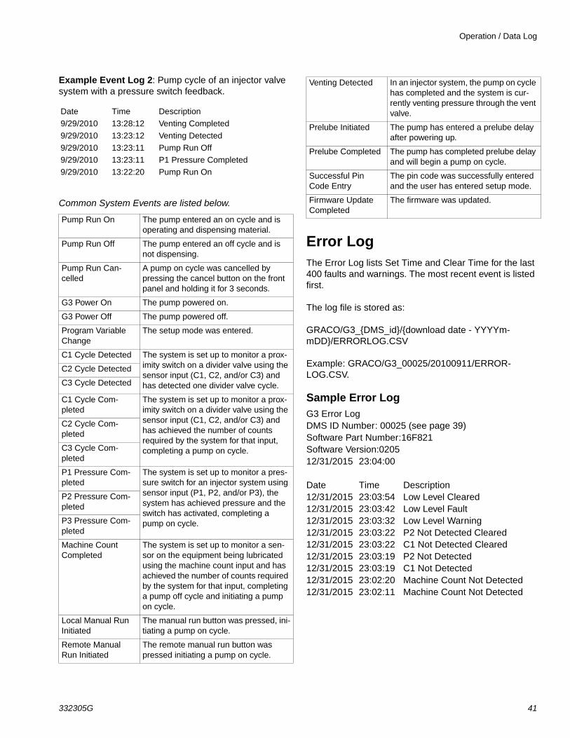
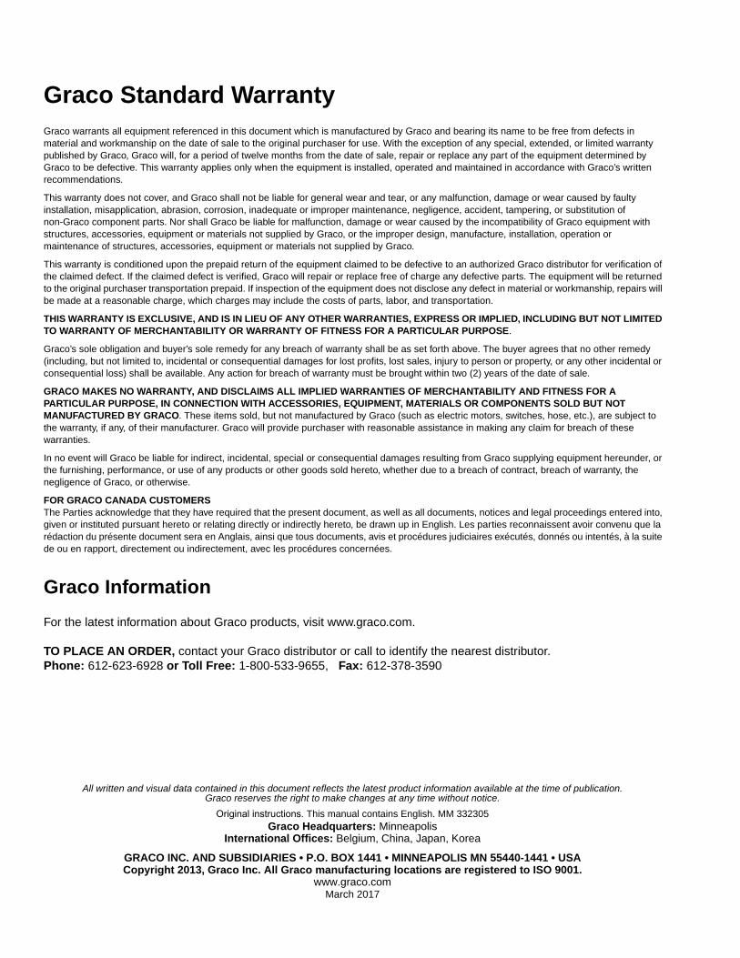
Example Event Log 2: Pump cycle of an injector valve system with a pressure switch feedback.
Common System Events are listed below.
Error Log The Error Log lists Set Time and Clear Time for the last 400 faults and warnings. The most recent event is listed first.
The log file is stored as:
GRACO/G3_{DMS_id}/{download date - YYYYm-mDD}/ERRORLOG.CSV
Example: GRACO/G3_00025/20100911/ERROR-LOG.CSV.
Sample Error Log
Date Time Description
9/29/2010 13:28:12 Venting Completed
9/29/2010 13:23:12 Venting Detected
9/29/2010 13:23:11 Pump Run Off9/29/2010 13:23:11 P1 Pressure Completed
9/29/2010 13:22:20 Pump Run On
Pump Run On The pump entered an on cycle and is operating and dispensing material.
Pump Run Off The pump entered an off cycle and is not dispensing.
Pump Run Can-celled
A pump on cycle was cancelled by pressing the cancel button on the front panel and holding it for 3 seconds.
G3 Power On The pump powered on.
G3 Power Off The pump powered off.
Program Variable Change
The setup mode was entered.
C1 Cycle Detected The system is set up to monitor a prox-imity switch on a divider valve using the sensor input (C1, C2, and/or C3) and has detected one divider valve cycle.
C2 Cycle Detected
C3 Cycle Detected
C1 Cycle Com-pleted
The system is set up to monitor a prox-imity switch on a divider valve using the sensor input (C1, C2, and/or C3) and has achieved the number of counts required by the system for that input, completing a pump on cycle.
C2 Cycle Com-pleted
C3 Cycle Com-pleted
P1 Pressure Com-pleted
The system is set up to monitor a pres-sure switch for an injector system using sensor input (P1, P2, and/or P3), the system has achieved pressure and the switch has activated, completing a pump on cycle.
P2 Pressure Com-pleted
P3 Pressure Com-pleted
Machine Count Completed
The system is set up to monitor a sen-sor on the equipment being lubricated using the machine count input and has achieved the number of counts required by the system for that input, completing a pump off cycle and initiating a pump on cycle.
Local Manual Run Initiated
The manual run button was pressed, ini-tiating a pump on cycle.
Remote Manual Run Initiated
The remote manual run button was pressed initiating a pump on cycle.
Venting Detected In an injector system, the pump on cycle has completed and the system is cur-rently venting pressure through the vent valve.
Prelube Initiated The pump has entered a prelube delay after powering up.
Prelube Completed The pump has completed prelube delay and will begin a pump on cycle.
Successful Pin Code Entry
The pin code was successfully entered and the user has entered setup mode.
Firmware Update Completed
The firmware was updated.
G3 Error LogDMS ID Number: 00025 (see page 39)Software Part Number:16F821Software Version:020512/31/2015 23:04:00
Date Time Description12/31/2015 23:03:54 Low Level Cleared12/31/2015 23:03:42 Low Level Fault12/31/2015 23:03:32 Low Level Warning12/31/2015 23:03:22 P2 Not Detected Cleared12/31/2015 23:03:22 C1 Not Detected Cleared12/31/2015 23:03:19 P2 Not Detected12/31/2015 23:03:19 C1 Not Detected12/31/2015 23:02:20 Machine Count Not Detected 12/31/2015 23:02:11 Machine Count Not Detected
Operation / Data Log
42 332305G
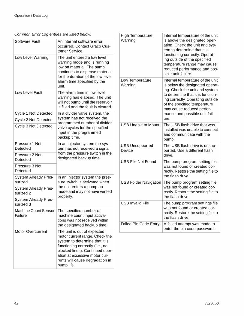
Common Error Log entries are listed below.
Software Fault An internal software error occurred. Contact Graco Cus-tomer Service.
Low Level Warning The unit entered a low level warning mode and is running low on material. The pump continues to dispense material for the duration of the low level alarm time specified by the unit.
Low Level Fault The alarm time in low level warning has elapsed. The unit will not pump until the reservoir is filled and the fault is cleared.
Cycle 1 Not Detected In a divider valve system, the system has not received the programmed number of divider valve cycles for the specified input in the programmed backup time.
Cycle 2 Not Detected
Cycle 3 Not Detected
Pressure 1 Not Detected
In an injector system the sys-tem has not received a signal from the pressure switch in the designated backup time.
Pressure 2 Not Detected
Pressure 3 Not Detected
System Already Pres-surized 1
In an injector system the pres-sure switch is activated when the unit enters a pump on mode and may not have vented properly.
System Already Pres-surized 2
System Already Pres-surized 3
Machine Count Sensor Failure
The specified number of machine count input activa-tions was not received within the designated backup time.
Motor Overcurrent The unit is out of expected motor current range. Check the system to determine that it is functioning correctly (i.e., no blocked lines). Continued oper-ation at excessive motor cur-rents will cause degradation in pump life.
High Temperature Warning
Internal temperature of the unit is above the designated oper-ating. Check the unit and sys-tem to determine that it is functioning correctly. Operat-ing outside of the specified temperature range may cause reduced performance and pos-sible unit failure.
Low Temperature Warning
Internal temperature of the unit is below the designated operat-ing. Check the unit and system to determine that it is function-ing correctly. Operating outside of the specified temperature may cause reduced perfor-mance and possible unit fail-ure.
USB Unable to Mount The USB flash drive that was installed was unable to connect and communicate with the pump.
USB Unsupported Device
The USB flash drive is unsup-ported. Use a different flash drive.
USB File Not Found The pump program setting file was not found or created cor-rectly. Restore the setting file to the flash drive.
USB Folder Navigation The pump program setting file was not found or created cor-rectly. Restore the setting file to the flash drive.
USB Invalid File The pump program settings file was not found or created cor-rectly. Restore the setting file to the flash drive.
Failed Pin Code Entry A failed attempt was made to enter the pin code password.
Operation / Data Log
332305G 43
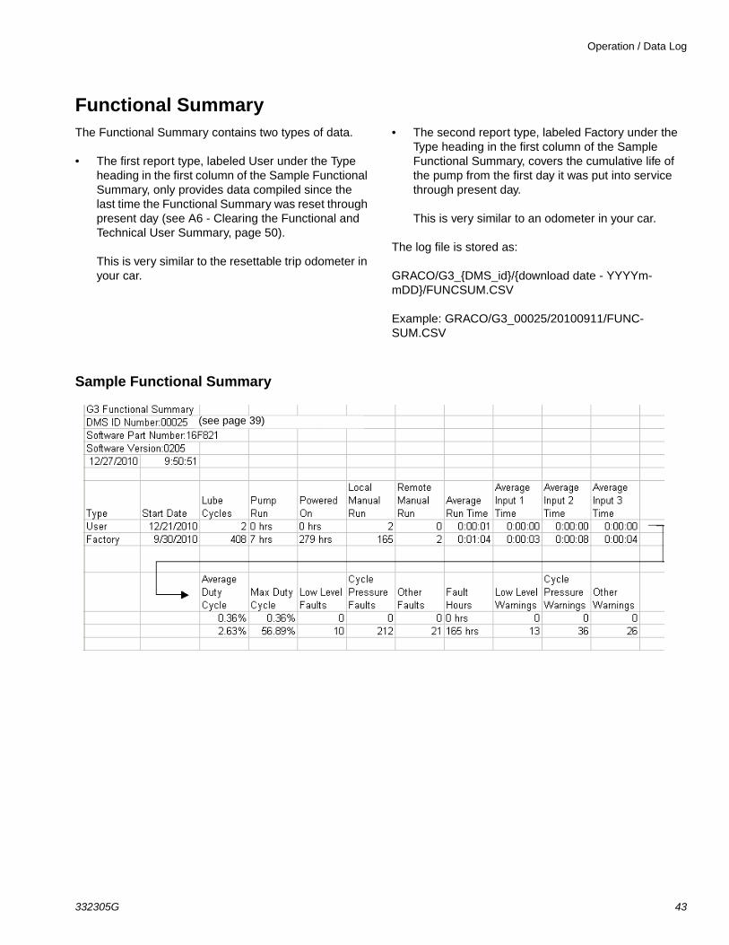
Functional SummaryThe Functional Summary contains two types of data.
• The first report type, labeled User under the Type heading in the first column of the Sample Functional Summary, only provides data compiled since the last time the Functional Summary was reset through present day (see A6 - Clearing the Functional and Technical User Summary, page 50).
This is very similar to the resettable trip odometer in your car.
• The second report type, labeled Factory under the Type heading in the first column of the Sample Functional Summary, covers the cumulative life of the pump from the first day it was put into service through present day.
This is very similar to an odometer in your car.
The log file is stored as:
GRACO/G3_{DMS_id}/{download date - YYYYm-mDD}/FUNCSUM.CSV
Example: GRACO/G3_00025/20100911/FUNC-SUM.CSV
Sample Functional Summary
(see page 39)
Operation / Data Log
44 332305G
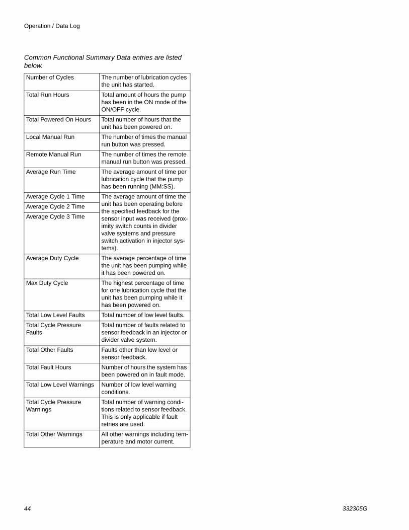
Common Functional Summary Data entries are listed below.
Number of Cycles The number of lubrication cycles the unit has started.
Total Run Hours Total amount of hours the pump has been in the ON mode of the ON/OFF cycle.
Total Powered On Hours Total number of hours that the unit has been powered on.
Local Manual Run The number of times the manual run button was pressed.
Remote Manual Run The number of times the remote manual run button was pressed.
Average Run Time The average amount of time per lubrication cycle that the pump has been running (MM:SS).
Average Cycle 1 Time The average amount of time the unit has been operating before the specified feedback for the sensor input was received (prox-imity switch counts in divider valve systems and pressure switch activation in injector sys-tems).
Average Cycle 2 Time
Average Cycle 3 Time
Average Duty Cycle The average percentage of time the unit has been pumping while it has been powered on.
Max Duty Cycle The highest percentage of time for one lubrication cycle that the unit has been pumping while it has been powered on.
Total Low Level Faults Total number of low level faults.
Total Cycle Pressure Faults
Total number of faults related to sensor feedback in an injector or divider valve system.
Total Other Faults Faults other than low level or sensor feedback.
Total Fault Hours Number of hours the system has been powered on in fault mode.
Total Low Level Warnings Number of low level warning conditions.
Total Cycle Pressure Warnings
Total number of warning condi-tions related to sensor feedback. This is only applicable if fault retries are used.
Total Other Warnings All other warnings including tem-perature and motor current.
Operation / Data Log
332305G 45
Technical SummaryThe Technical Summary contains two types of data.
• The first report only provides data compiled since the Pump Summary was reset to present day (see A6 - Clearing the Functional and Technical User Summary).
This is very similar to the resettable trip odometer in your car.
• The second is a report that covers the cumulative life of the pump from the first day it was put into ser-vice to present day.
This is very similar to an odometer in your car.
The log file is stored as:
GRACO/G3_{DMS_id}/{download date - YYYYm-mDD}/TECHSUM.CSV
Example: GRACO/G3_00025/20100911/TECH-SUM.CSV
Common Technical Summary Data entries are listed below.
Sample Technical Summary
Average Input Board Voltage (DC)
The average input voltage mea-sured by the internal circuit board.
Peak Input Board Voltage (DC)
The peak input voltage measured by the internal circuit board.
Average Motor Current The average motor current mea-sured by the unit.
Peak Motor Current The peak motor current mea-sured by the unit.
Average Internal Tem-perature
The average internal temperature seen by the unit.
Peak Internal Tempera-ture
The peak internal temperature seen by the unit.
Low Internal Tempera-ture
The lowest internal temperature seen by the unit.
G3 Technical SummaryDMS ID Number: 00025 (see page 39)Software Part Number:16F821Software Version: 020512/27/2010
9:50:51
Latest Values Temp Voltage31C 23.877
Type Start Date Average Board Voltage
Peak Board Voltage
Average Motor Current
Peak Motor Current
Average Internal Temp
Peak Internal Temp
Low Internal Temp
User 12/21/2010
23.877 23.877 0.062 0.062 30C 35C 28C
Factory 9/30/2010 22.804 23.877 1.091 0.362 33C 42C -10C
Advanced Programming
46 332305G
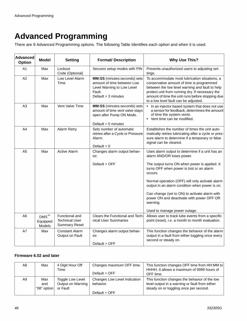
Advanced ProgrammingThere are 9 Advanced Programming options. The following Table Identifies each option and when it is used.
Firmware 6.02 and later
Advanced Option
Model Setting Format/ Description Why Use This?
A1 Max Lockout Code (Optional)
Secures setup modes with PIN Prevents unauthorized users to adjusting set-tings.
A2 Max Low Level Alarm Time
MM:SS (minutes:seconds) sets amount of time between Low Level Warning to Low Level Fault.Default = 3 minutes
To accommodate most lubrication situations, a conservative amount of time is programmed between the low level warning and fault to help protect unit from running dry. If necessary the amount of time the unit runs before stopping due to a low level fault can be adjusted.
A3 Max Vent Valve Time MM:SS (minutes:seconds) sets amount of time vent valve stays open after Pump ON Mode.
Default = 5 minutes
• In an injector based system that does not use a sensor for feedback, determines the amount of time the system vents.
• Vent time can be modified.
A4 Max Alarm Retry Sets number of automatic retries after a Cycle or Pressure Alarm.
Default = 0
Establishes the number of times the unit auto-matically retries lubricating after a cycle or pres-sure alarm to determine if a temporary or false signal can be cleared.
A5 Max Active Alarm Changes alarm output behav-ior.
Default = OFF
Uses alarm output to determine if a unit has an alarm AND/OR loses power.
The output turns ON when power is applied. It turns OFF when power is lost or an alarm occurs.
Normal operation (OFF) will only activate alarm output in an alarm condition when power is on.
Can change (set to ON) to activate alarm with power ON and deactivate with power OFF OR warning.
Used to manage power outage.
A6 DMS™ Equipped Models
Functional and Technical User Summary Reset
Clears the Functional and Tech-nical User Summaries
Allows user to track lube events from a specific point (reset), i.e. a month to month evaluation.
A7 Max Constant Alarm Output on Fault
Changes alarm output behav-ior.
Default = OFF
This function changes the behavior of the alarm output in a fault from either toggling once every second or steady on.
A8 Max 4 Digit Hour Off Time
Changes maximum OFF time.
Default = OFF
This function changes OFF time from HH:MM to HHHH. It allows a maximum of 9999 hours of OFF time.
A9 Max and
“08” option
Toggle Low Level Output on Warning or Fault
Changes Low Level Indication behavior.
Default = OFF
This function changes the behavior of the low level output in a warning or fault from either steady on or toggling once per second.
Advanced Programming
332305G 47
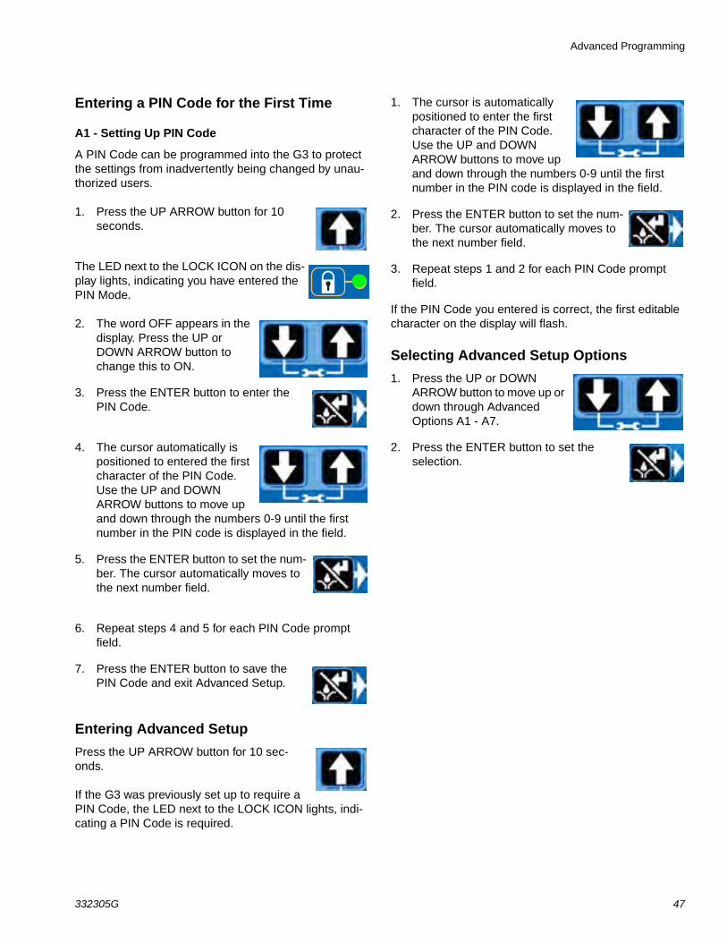
Entering a PIN Code for the First Time
A1 - Setting Up PIN Code
A PIN Code can be programmed into the G3 to protect the settings from inadvertently being changed by unau-thorized users.
1. Press the UP ARROW button for 10 seconds.
The LED next to the LOCK ICON on the dis-play lights, indicating you have entered the PIN Mode.
2. The word OFF appears in the display. Press the UP or DOWN ARROW button to change this to ON.
3. Press the ENTER button to enter the PIN Code.
4. The cursor automatically is positioned to entered the first character of the PIN Code. Use the UP and DOWN ARROW buttons to move up and down through the numbers 0-9 until the first number in the PIN code is displayed in the field.
5. Press the ENTER button to set the num-ber. The cursor automatically moves to the next number field.
6. Repeat steps 4 and 5 for each PIN Code prompt field.
7. Press the ENTER button to save the PIN Code and exit Advanced Setup.
Entering Advanced Setup
Press the UP ARROW button for 10 sec-onds.
If the G3 was previously set up to require a PIN Code, the LED next to the LOCK ICON lights, indi-cating a PIN Code is required.
1. The cursor is automatically positioned to enter the first character of the PIN Code. Use the UP and DOWN ARROW buttons to move up and down through the numbers 0-9 until the first number in the PIN code is displayed in the field.
2. Press the ENTER button to set the num-ber. The cursor automatically moves to the next number field.
3. Repeat steps 1 and 2 for each PIN Code prompt field.
If the PIN Code you entered is correct, the first editable character on the display will flash.
Selecting Advanced Setup Options
1. Press the UP or DOWN ARROW button to move up or down through Advanced Options A1 - A7.
2. Press the ENTER button to set the selection.
Advanced Programming
48 332305G
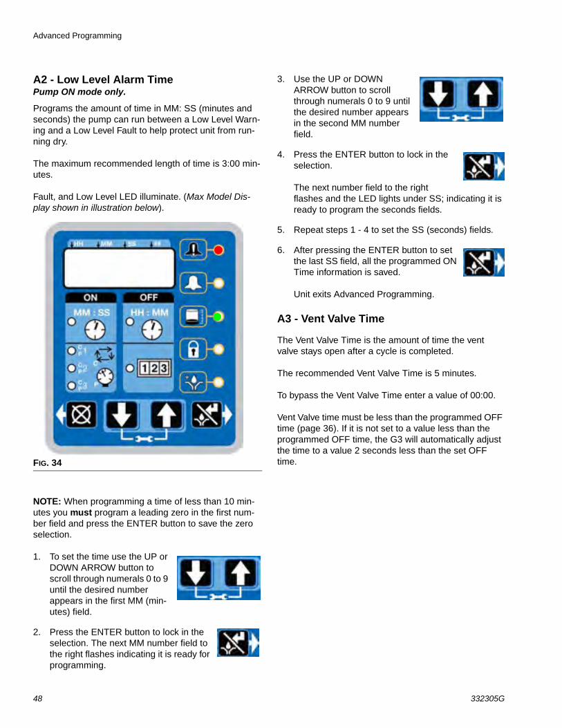
A2 - Low Level Alarm TimePump ON mode only.
Programs the amount of time in MM: SS (minutes and seconds) the pump can run between a Low Level Warn-ing and a Low Level Fault to help protect unit from run-ning dry.
The maximum recommended length of time is 3:00 min-utes.
Fault, and Low Level LED illuminate. (Max Model Dis-play shown in illustration below).
NOTE: When programming a time of less than 10 min-utes you must program a leading zero in the first num-ber field and press the ENTER button to save the zero selection.
1. To set the time use the UP or DOWN ARROW button to scroll through numerals 0 to 9 until the desired number appears in the first MM (min-utes) field.
2. Press the ENTER button to lock in the selection. The next MM number field to the right flashes indicating it is ready for programming.
3. Use the UP or DOWN ARROW button to scroll through numerals 0 to 9 until the desired number appears in the second MM number field.
4. Press the ENTER button to lock in the selection.
The next number field to the right flashes and the LED lights under SS; indicating it is ready to program the seconds fields.
5. Repeat steps 1 - 4 to set the SS (seconds) fields.
6. After pressing the ENTER button to set the last SS field, all the programmed ON Time information is saved.
Unit exits Advanced Programming.
A3 - Vent Valve Time
The Vent Valve Time is the amount of time the vent valve stays open after a cycle is completed.
The recommended Vent Valve Time is 5 minutes.
To bypass the Vent Valve Time enter a value of 00:00.
Vent Valve time must be less than the programmed OFF time (page 36). If it is not set to a value less than the programmed OFF time, the G3 will automatically adjust the time to a value 2 seconds less than the set OFF time.FIG. 34
Advanced Programming
332305G 49
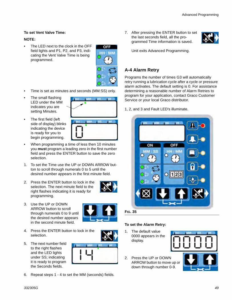
To set Vent Valve Time:
NOTE:
• The LED next to the clock in the OFF field lights and P1, P2, and P3, indi-cating the Vent Valve Time is being programmed.
• Time is set as minutes and seconds (MM:SS) only.
• The small flashing LED under the MM indicates you are setting Minutes.
• The first field (left side of display) blinks indicating the device is ready for you to begin programming.
• When programming a time of less then 10 minutes you must program a leading zero in the first number field and press the ENTER button to save the zero selection.
1. To set the Time use the UP or DOWN ARROW but-ton to scroll through numerals 0 to 5 until the desired number appears in the first minute field.
2. Press the ENTER button to lock in the selection. The next minute field to the right flashes indicating it is ready for programming.
3. Use the UP or DOWN ARROW button to scroll through numerals 0 to 9 until the desired number appears in the second minute field.
4. Press the ENTER button to lock in the selection.
5. The next number field to the right flashes and the LED lights under SS; indicating it is ready to program the Seconds fields.
6. Repeat steps 1 - 4 to set the MM (seconds) fields.
7. After pressing the ENTER button to set the last seconds field, all the pro-grammed Time information is saved.
Unit exits Advanced Programming.
A-4 Alarm Retry
Programs the number of times G3 will automatically retry running a lubrication cycle after a cycle or pressure alarm activates. The default setting is 0. For assistance determining a reasonable number of Alarm Retries to program for your application, contact Graco Customer Service or your local Graco distributor.
1, 2, and 3 and Fault LED’s illuminate.
To set the Alarm Retry:
1. The default value 0000 appears in the display.
2. Press the UP or DOWN ARROW button to move up or down through number 0-9.
FIG. 35
Advanced Programming
50 332305G
3. When the correct number displays, press the ENTER button to set the num-ber.
4. Repeat 2 - 3 to set the remaining fields.
5. Press the ENTER button to exit Advanced Programming.
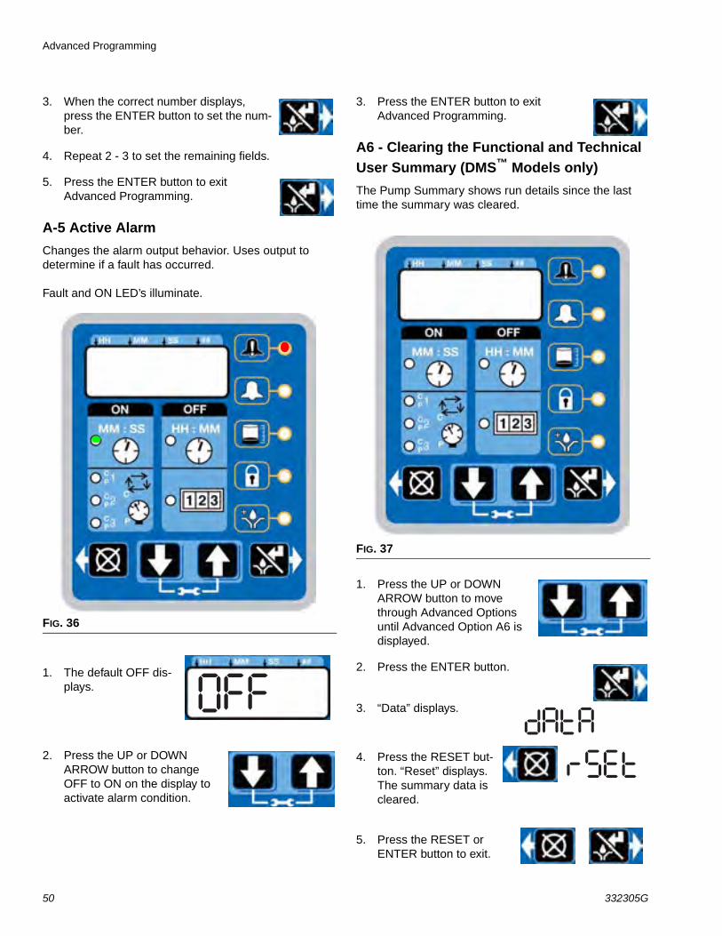
A-5 Active Alarm
Changes the alarm output behavior. Uses output to determine if a fault has occurred.
Fault and ON LED’s illuminate.
1. The default OFF dis-plays.
2. Press the UP or DOWN ARROW button to change OFF to ON on the display to activate alarm condition.
3. Press the ENTER button to exit Advanced Programming.
A6 - Clearing the Functional and Technical User Summary (DMS™ Models only)
The Pump Summary shows run details since the last time the summary was cleared.
1. Press the UP or DOWN ARROW button to move through Advanced Options until Advanced Option A6 is displayed.
2. Press the ENTER button.
3. “Data” displays.
4. Press the RESET but-ton. “Reset” displays. The summary data is cleared.
5. Press the RESET or ENTER button to exit.
FIG. 36
FIG. 37
Advanced Programming
332305G 51
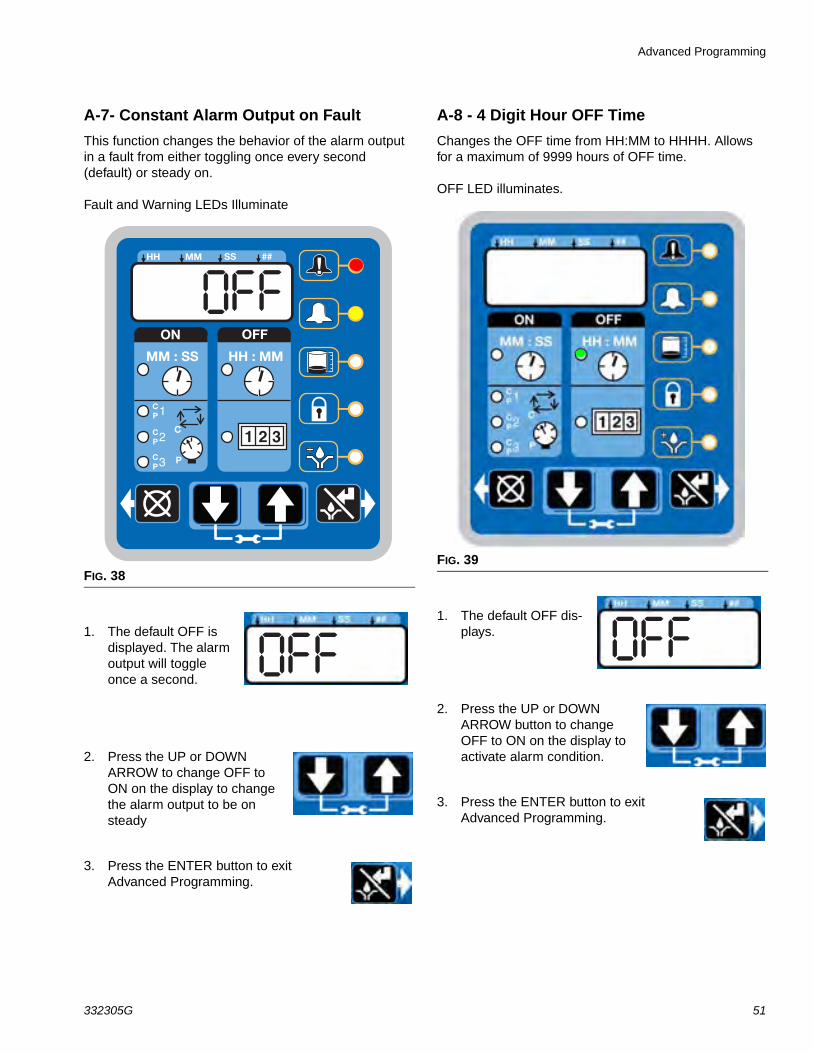
A-7- Constant Alarm Output on Fault
This function changes the behavior of the alarm output in a fault from either toggling once every second (default) or steady on.
Fault and Warning LEDs Illuminate
1. The default OFF is displayed. The alarm output will toggle once a second.
2. Press the UP or DOWN ARROW to change OFF to ON on the display to change the alarm output to be on steady
3. Press the ENTER button to exit Advanced Programming.
A-8 - 4 Digit Hour OFF Time
Changes the OFF time from HH:MM to HHHH. Allows for a maximum of 9999 hours of OFF time.
OFF LED illuminates.
1. The default OFF dis-plays.
2. Press the UP or DOWN ARROW button to change OFF to ON on the display to activate alarm condition.
3. Press the ENTER button to exit Advanced Programming.
FIG. 38
ON OFF
!
1 2 3
HH MM SS ##
MM : SS HH : MM
2
3
1
P
CCP
CP
CP
FIG. 39
Advanced Programming
52 332305G
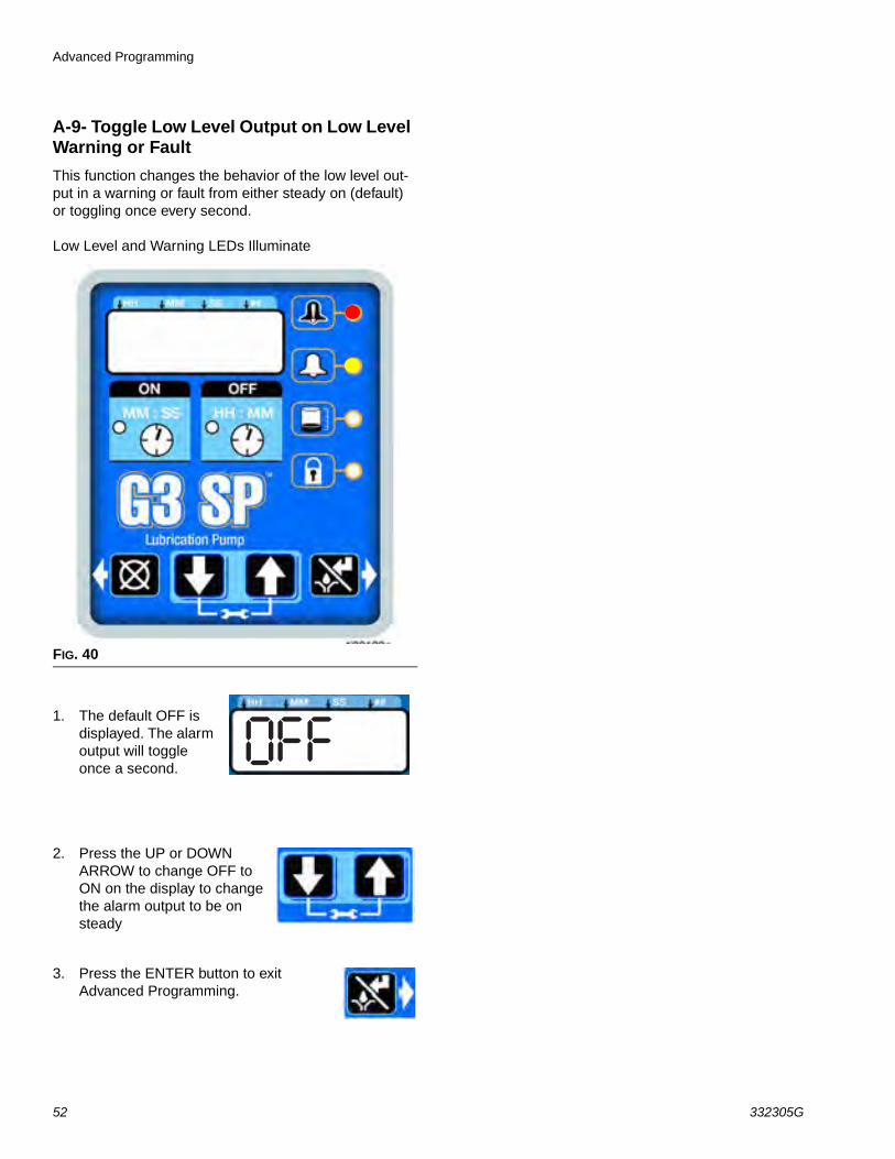
A-9- Toggle Low Level Output on Low Level Warning or Fault
This function changes the behavior of the low level out-put in a warning or fault from either steady on (default) or toggling once every second.
Low Level and Warning LEDs Illuminate
1. The default OFF is displayed. The alarm output will toggle once a second.
2. Press the UP or DOWN ARROW to change OFF to ON on the display to change the alarm output to be on steady
3. Press the ENTER button to exit Advanced Programming.
FIG. 40
Run Mode
332305G 53
Run Mode
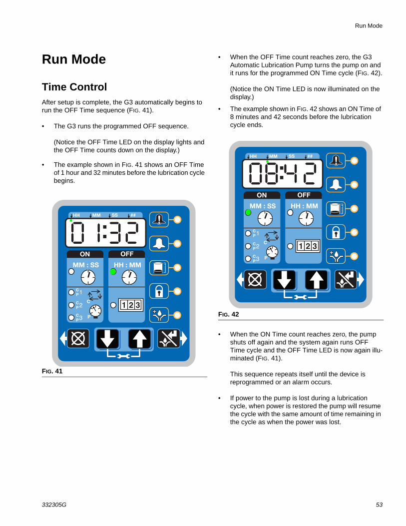
Time ControlAfter setup is complete, the G3 automatically begins to run the OFF Time sequence (FIG. 41).
• The G3 runs the programmed OFF sequence.
(Notice the OFF Time LED on the display lights and the OFF Time counts down on the display.)
• The example shown in FIG. 41 shows an OFF Time of 1 hour and 32 minutes before the lubrication cycle begins.
• When the OFF Time count reaches zero, the G3 Automatic Lubrication Pump turns the pump on and it runs for the programmed ON Time cycle (FIG. 42).
(Notice the ON Time LED is now illuminated on the display.)
• The example shown in FIG. 42 shows an ON Time of 8 minutes and 42 seconds before the lubrication cycle ends.
• When the ON Time count reaches zero, the pump shuts off again and the system again runs OFF Time cycle and the OFF Time LED is now again illu-minated (FIG. 41).
This sequence repeats itself until the device is reprogrammed or an alarm occurs.
• If power to the pump is lost during a lubrication cycle, when power is restored the pump will resume the cycle with the same amount of time remaining in the cycle as when the power was lost.
FIG. 41
ON OFF
!
1 2 3
HH MM SS ##
MM : SS HH : MM
2
3
1
P
CCP
CP
CP
FIG. 42
ON OFF
!
1 2 3
HH MM SS ##
MM : SS HH : MM
2
3
1
P
CCP
CP
CP
Run Mode
54 332305G
Lubrication Mode (Pump ON) Controls
In Max models the Lubrication Mode (Pump ON) can be controlled by either cycle and/or pressure sensors.
If cycle and/or pressure controls have been set to some-thing other than OFF the display will alternate between cycles (C1, C2, C3) and/or active sensors (P1, P2, P3) and Backup Time.
If cycle or pressure controls have been set to OFF then the Lubrication Mode (Pump ON) will be controlled by On Time (see Time Control, page 53).
With cycle and/or pressure controls set, the lubrication cycle (Pump ON) is ended by meeting all required cycle and/or pressure settings.
Cycle Control
• A set number of triggered counts in a cycle based system (C1). Typically a proximity switch connected to a divider valve.
• The LED next to the appropriate sensor (C/P1, C/P2, C/P3) illuminates.
• The display indicates the sensor (C1, C2, C3) and the remaining cycles for that sensor (FIG. 43).
The example shown in FIG. 43 shows sensor C1 with 5 cycles remaining.
Pressure Control
• A single triggered count in a pressure based system (P1). Typically a pressure switch on the end of a line of injectors.
• The LED next to the appropriate sensor (C/P1, C/P2, C/P3) illuminates (FIG. 44 and FIG. 45).
• The display indicates the sensor (P1, P2, P3) and whether the pressure switch for that sensor has been triggered or not.
- 01 = pressure switch has not been triggered - 00 = pressure switch is triggered.
The example shown in FIG. 44 shows sensor P1 with a pressure switch that has been triggered.
FIG. 45 (page 55) shows sensor P2 with a pres-sure switch that has NOT been triggered.
FIG. 43
ON OFF
!
1 2 3
HH MM SS ##
MM : SS HH : MM
2
3
1
P
CCP
CP
CP
FIG. 44
ON OFF
!
1 2 3
HH MM SS ##
MM : SS HH : MM
2
3
1
P
CCP
CP
CP
Run Mode
332305G 55
Backup Time
• In both Cycle and Pressure modes a Backup Time (maximum run time) has been set.
• The LED(s) next to all programmed sensors (C/P1, C/P2, C/P3) illuminate.
• The display shows time remaining until a fault.
The example shown in FIG. 46 shows 14 min-utes and 33 seconds left until the fault occurs.
• If all cycle and/or pressure requirements are met the unit exits the lubrication cycle (Pump ON) and enter the rest cycle (Pump OFF).
Rest Mode (Pump OFF) Controls
In Max models the Rest Mode (Pump OFF) is controlled by machine counts.
If the Machine Count is set to a value greater than 0000 and the Backup Time option is activated, the display will alternate between Machine Counts and Backup Time.
If Machine Count has been set to a value greater than 0000 and the Backup Time option is NOT activated, the display will only show the number of Machines Counts remaining.
FIG. 45
ON OFF
!
1 2 3
HH MM SS ##
MM : SS HH : MM
2
3
1
P
CCP
CP
CP
FIG. 46
ON OFF
!
1 2 3
HH MM SS ##
MM : SS HH : MM
2
3
1
P
CCP
CP
CP
Run Mode
56 332305G
With machine count set, the Rest Cycle (Pump OFF) is ended when the machine count reaches zero (0000).
Machine Count
• A set number of triggered counts.
• The LED next to 1-2-3 illuminates (FIG. 47).
• The display indicates the number of machine counts remaining.
The example shown in FIG. 47 shows the remaining number of machine counts is 0045.
Backup Time
In Machine Count mode, if a Backup Time (maximum rest time) has been set:
• The LED next to 1-2-3 illuminates (FIG. 48).
• The display shows the amount of time remain-ing till a fault.
The example shown in FIG. 48 shows 4 hours and 17 minutes remaining until a fault occurs.
• If the Machine Count requirements are met the unit will exit the Rest Mode (Pump OFF) and enter the Lubrication Mode (Pump ON).
OFF Time
In Max models if the Machine Count is set to 0000 then Reset Mode (Pump OFF) is controlled with OFF Time (see Time Control, page 53).
FIG. 47
ON OFF
!
1 2 3
HH MM SS ##
MM : SS HH : MM
2
3
1
P
CCP
CP
CP
FIG. 48
ON OFF
!
1 2 3
HH MM SS ##
MM : SS HH : MM
2
3
1
P
CCP
CP
CP
Run Mode
332305G 57
Additional Controls
Venting
In Max models a Vent Time can be set using the Advanced Programming mode (page 48). This is typi-cally done in a Pressure Based System (P1) to allow injectors to reset.
• Unit vents for a set amount of time (not dis-played).
• The LED’s next to C/P1, C/P2, C/P3 flash while unit is venting.
• If Machine Count is set, the display will alternate between machine counts remaining and backup time (Max Model Rest Mode, page 55).
• If Machine Count has been set the LED next to 1-2-3 illuminates (FIG. 47, page 56).
• If Machine Count has not been set the display shows OFF Time (See Time Control, page 53).
• If Machine Count has not been set the LED next to the clock in the OFF field illuminates (See Time Control, page 53).
Prelube / Prelube Delay
In all models a power OFF/ON cycle can be controlled with the Prelube and Prelube Delay functions.
Prelube
The Prelube function has been selected. Prelube delay is set to 00:00:
• Power to the unit cycles OFF then ON.
• Unit immediately begins a lubrication cycle.
• Max Model - display shows Cycle/Pres-sure/Backup Time (See Max Model Lubrication Mode Controls, page 54).
Prelube Delay
The Prelube function has been selected. Prelube delay is set to something other than 00:00:
• Power to the unit cycles OFF then ON.
• Unit immediately begins the Prelube Delay count down until the lubrication cycle begins.
• The LED next to the clock in the OFF field is illu-minated (FIG. 49).
• The Prelube LED lights (FIG. 49).
• The display shows time remaining until lubrica-tion cycle begins. The example shown in FIG. 49 shows 8 minutes and 14 seconds left until a lubrication cycle begins.
Manual Run Cycle
To run an extra (non-programmed) lubrica-tion cycle, push the Manual Start button.
NOTE: Manual Run option is not available while unit is in Vent Mode.
FIG. 49
ON OFF
!
1 2 3
HH MM SS ##
MM : SS HH : MM
2
3
1
P
CCP
CP
CP
Alarms: Firmware Versions 6.01 and Below
58 332305G
Alarms: Firmware Versions 6.01 and BelowAny time a Fault / Warning occurs, a combination of LED’s will illuminate to notify you there is a problem and help identify the kind of Fault / Warning has occurred.
• Faults and Warnings will not automatically clear.
• To clear an fault, press and hold the RESET button on the display button pad for 3 seconds.
• To clear a warning press and immediately release the RESET button.
Fault / Warning ScenariosThe following pages describe the most likely fault / warnings you could receive.
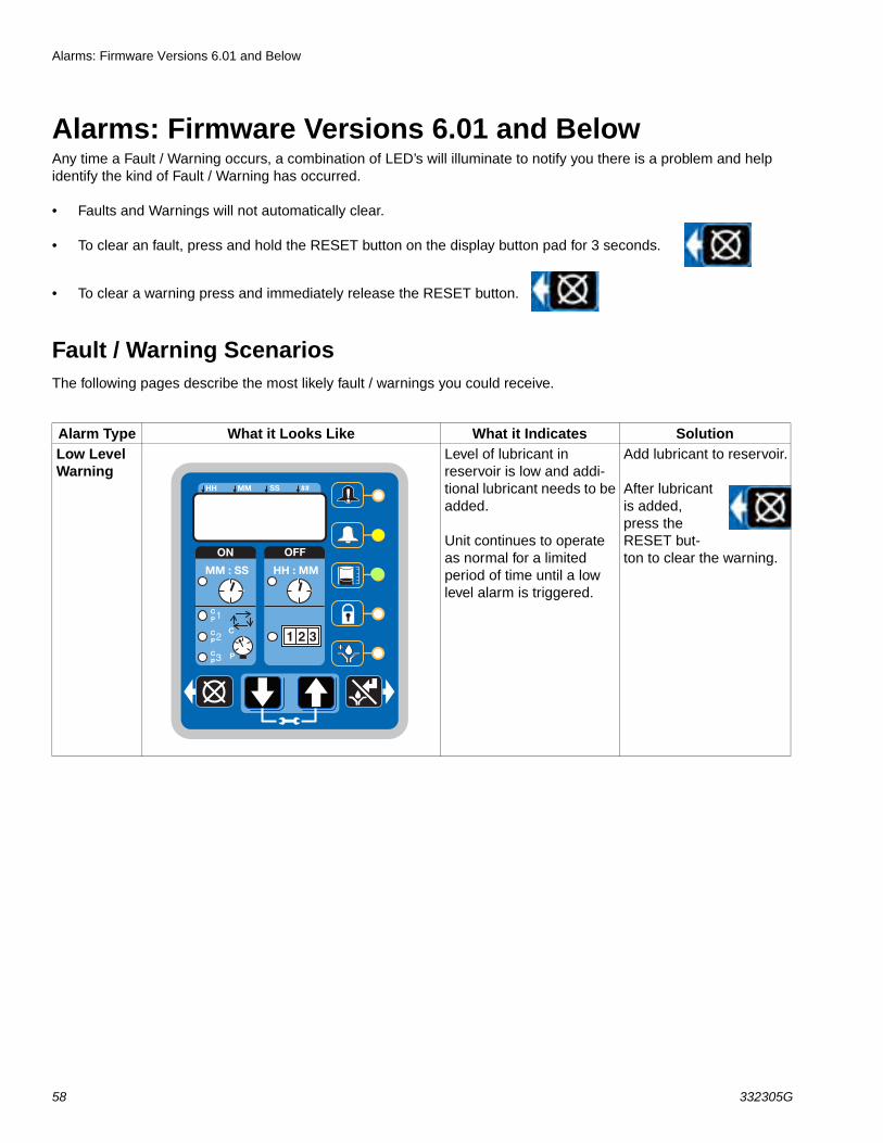
Alarm Type What it Looks Like What it Indicates SolutionLow Level Warning
Level of lubricant in reservoir is low and addi-tional lubricant needs to be added.
Unit continues to operate as normal for a limited period of time until a low level alarm is triggered.
Add lubricant to reservoir.
After lubricant is added, press the RESET but-ton to clear the warning.ON OFF
!
1 2 3
HH MM SS ##
MM : SS HH : MM
2
3
1
P
CCP
CP
CP
Alarms: Firmware Versions 6.01 and Below
332305G 59
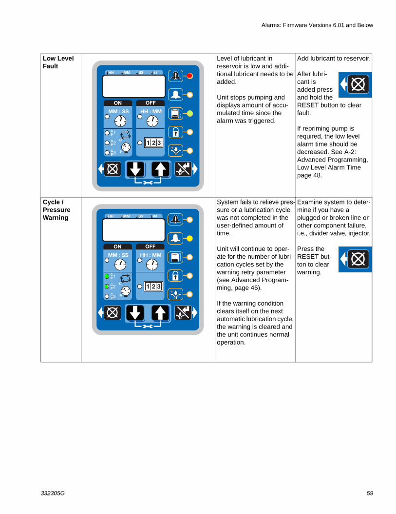
Low Level Fault
Level of lubricant in reservoir is low and addi-tional lubricant needs to be added.
Unit stops pumping and displays amount of accu-mulated time since the alarm was triggered.
Add lubricant to reservoir.
After lubri-cant is added press and hold the RESET button to clear fault.
If repriming pump is required, the low level alarm time should be decreased. See A-2: Advanced Programming, Low Level Alarm Time page 48.
Cycle / Pressure Warning
System fails to relieve pres-sure or a lubrication cycle was not completed in the user-defined amount of time.
Unit will continue to oper-ate for the number of lubri-cation cycles set by the warning retry parameter (see Advanced Program-ming, page 46).
If the warning condition clears itself on the next automatic lubrication cycle, the warning is cleared and the unit continues normal operation.
Examine system to deter-mine if you have a plugged or broken line or other component failure, i.e., divider valve, injector.
Press the RESET but-ton to clear warning.
ON OFF
!
1 2 3
HH MM SS ##
MM : SS HH : MM
2
3
1
P
CCP
CP
CP
ON OFF
!
1 2 3
HH MM SS ##
MM : SS HH : MM
2
3
1
P
CCP
CP
CP
Alarms: Firmware Versions 6.01 and Below
60 332305G
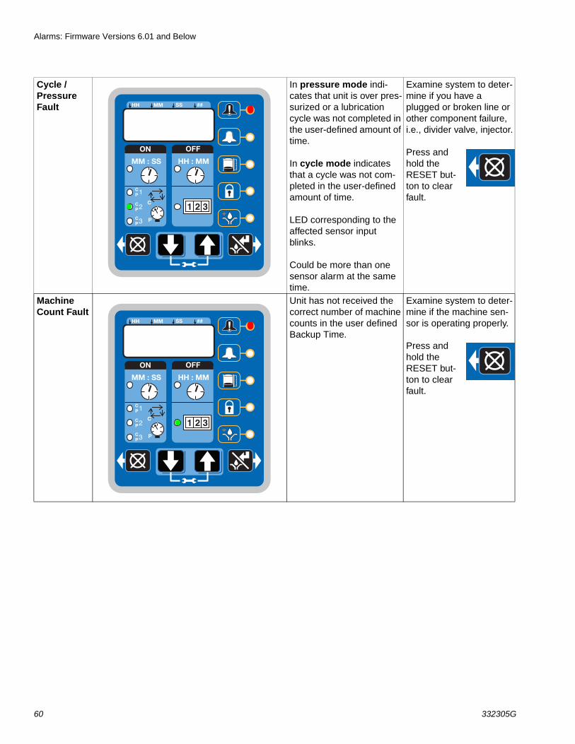
Cycle / Pressure Fault
In pressure mode indi-cates that unit is over pres-surized or a lubrication cycle was not completed in the user-defined amount of time.
In cycle mode indicates that a cycle was not com-pleted in the user-defined amount of time.
LED corresponding to the affected sensor input blinks.
Could be more than one sensor alarm at the same time.
Examine system to deter-mine if you have a plugged or broken line or other component failure, i.e., divider valve, injector.
Press and hold the RESET but-ton to clear fault.
Machine Count Fault
Unit has not received the correct number of machine counts in the user defined Backup Time.
Examine system to deter-mine if the machine sen-sor is operating properly.
Press and hold the RESET but-ton to clear fault.
ON OFF
!
1 2 3
HH MM SS ##
MM : SS HH : MM
2
3
1
P
CCP
CP
CP
ON OFF
!
1 2 3
HH MM SS ##
MM : SS HH : MM
2
3
1
P
CCP
CP
CP

Alarms: Firmware Versions 6.01 and Below
332305G 61
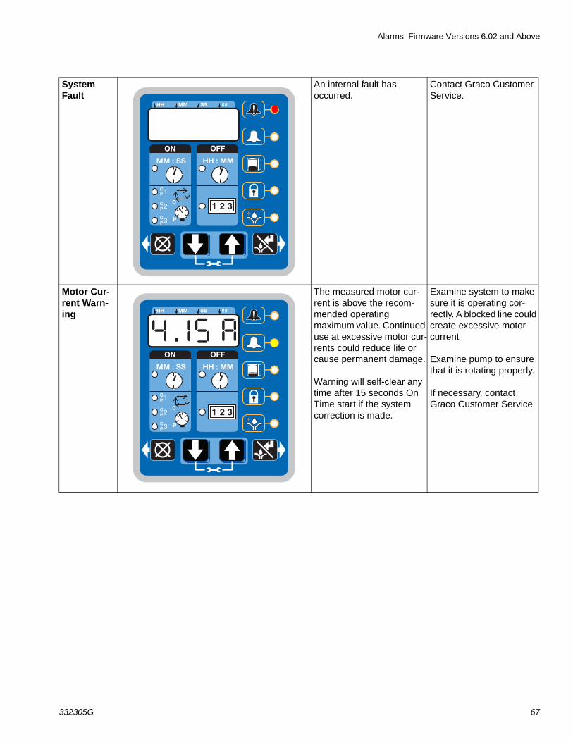
System Fault
An internal fault has occurred.
Contact Graco Customer Service.
Motor Cur-rent Warn-ing
The measured motor cur-rent is above the recom-mended operating maximum value. Continued use at excessive motor cur-rents could reduce life or cause permanent damage.
Examine system to make sure it is operating cor-rectly. A blocked line could create excessive motor current
Examine pump to ensure that it is rotating properly.
If necessary, contact Graco Customer Service.
ON OFF
!
1 2 3
HH MM SS ##
MM : SS HH : MM
2
3
1
P
CCP
CP
CP
ON OFF
!
1 2 3
HH MM SS ##
MM : SS HH : MM
2
3
1
P
CCP
CP
CP
Alarms: Firmware Versions 6.01 and Below
62 332305G
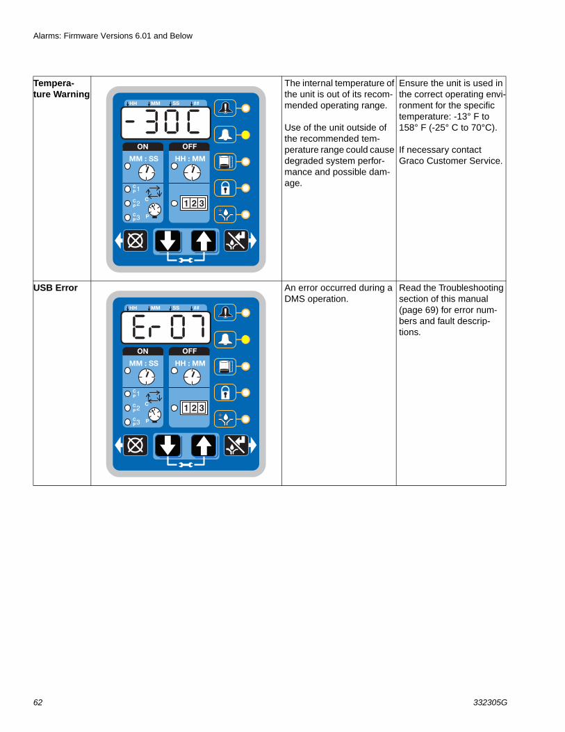
Tempera-ture Warning
The internal temperature of the unit is out of its recom-mended operating range.
Use of the unit outside of the recommended tem-perature range could cause degraded system perfor-mance and possible dam-age.
Ensure the unit is used in the correct operating envi-ronment for the specific temperature: -13° F to 158° F (-25° C to 70°C).
If necessary contact Graco Customer Service.
USB Error An error occurred during a DMS operation.
Read the Troubleshooting section of this manual (page 69) for error num-bers and fault descrip-tions.
ON OFF
!
1 2 3
HH MM SS ##
MM : SS HH : MM
2
3
1
P
CCP
CP
CP
ON OFF
!
1 2 3
HH MM SS ##
MM : SS HH : MM
2
3
1
P
CCP
CP
CP
Alarms: Firmware Versions 6.02 and Above
332305G 63
Alarms: Firmware Versions 6.02 and AboveAny time a Fault / Warning occurs, a combination of LED’s will illuminate to notify you there is a problem and help identify the kind of Fault / Warning has occurred. An error message will display and flash every 2 seconds for an alarm, temperature or current warning and every 10 seconds for all other types of warnings.
• Faults will not automatically clear.
• To clear an fault, press and hold the RESET button on the display button pad for 3 seconds.
• To clear a warning press and immediately release the RESET button.
Fault / Warning ScenariosThe following pages describe the most likely fault / warnings you could receive.
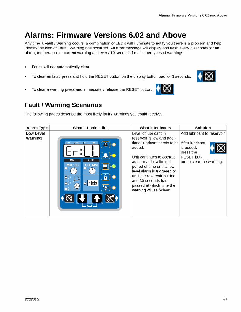
Alarm Type What it Looks Like What it Indicates SolutionLow Level Warning
Level of lubricant in reservoir is low and addi-tional lubricant needs to be added.
Unit continues to operate as normal for a limited period of time until a low level alarm is triggered or until the reservoir is filled and 30 seconds has passed at which time the warning will self-clear.
Add lubricant to reservoir.
After lubricant is added, press the RESET but-ton to clear the warning.ON OFF
!
1 2 3
HH MM SS ##
MM : SS HH : MM
2
3
1
P
CCP
CP
CP
Alarms: Firmware Versions 6.02 and Above
64 332305G
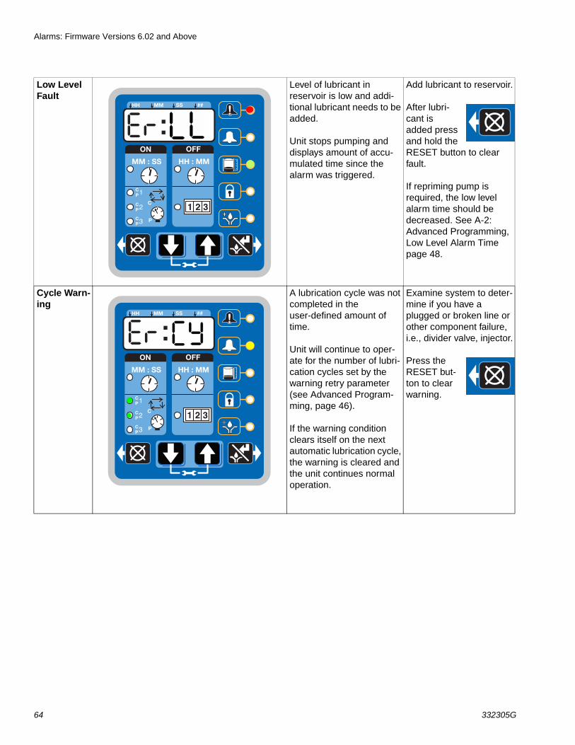
Low Level Fault
Level of lubricant in reservoir is low and addi-tional lubricant needs to be added.
Unit stops pumping and displays amount of accu-mulated time since the alarm was triggered.
Add lubricant to reservoir.
After lubri-cant is added press and hold the RESET button to clear fault.
If repriming pump is required, the low level alarm time should be decreased. See A-2: Advanced Programming, Low Level Alarm Time page 48.
Cycle Warn-ing
A lubrication cycle was not completed in the user-defined amount of time.
Unit will continue to oper-ate for the number of lubri-cation cycles set by the warning retry parameter (see Advanced Program-ming, page 46).
If the warning condition clears itself on the next automatic lubrication cycle, the warning is cleared and the unit continues normal operation.
Examine system to deter-mine if you have a plugged or broken line or other component failure, i.e., divider valve, injector.
Press the RESET but-ton to clear warning.
ON OFF
!
1 2 3
HH MM SS ##
MM : SS HH : MM
2
3
1
P
CCP
CP
CP
ON OFF
!
1 2 3
HH MM SS ##
MM : SS HH : MM
2
3
1
P
CCP
CP
CP
Alarms: Firmware Versions 6.02 and Above
332305G 65
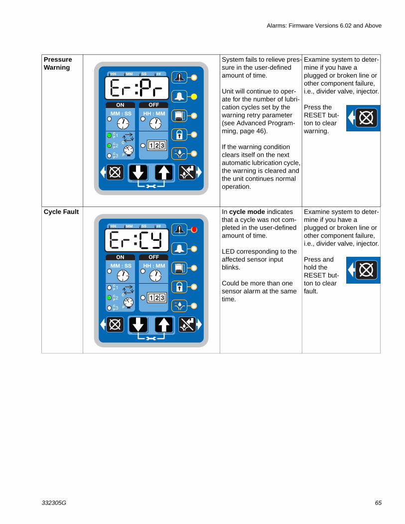
PressureWarning
System fails to relieve pres-sure in the user-defined amount of time.
Unit will continue to oper-ate for the number of lubri-cation cycles set by the warning retry parameter (see Advanced Program-ming, page 46).
If the warning condition clears itself on the next automatic lubrication cycle, the warning is cleared and the unit continues normal operation.
Examine system to deter-mine if you have a plugged or broken line or other component failure, i.e., divider valve, injector.
Press the RESET but-ton to clear warning.
Cycle Fault In cycle mode indicates that a cycle was not com-pleted in the user-defined amount of time.
LED corresponding to the affected sensor input blinks.
Could be more than one sensor alarm at the same time.
Examine system to deter-mine if you have a plugged or broken line or other component failure, i.e., divider valve, injector.
Press and hold the RESET but-ton to clear fault.
ON OFF
!
1 2 3
HH MM SS ##
MM : SS HH : MM
2
3
1
P
CCP
CP
CP
ON OFF
!
1 2 3
HH MM SS ##
MM : SS HH : MM
2
3
1
P
CCP
CP
CP
Alarms: Firmware Versions 6.02 and Above
66 332305G
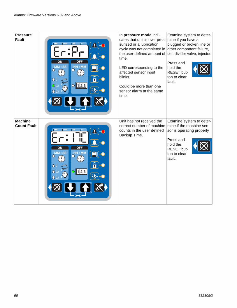
Pressure Fault
In pressure mode indi-cates that unit is over pres-surized or a lubrication cycle was not completed in the user-defined amount of time.
LED corresponding to the affected sensor input blinks.
Could be more than one sensor alarm at the same time.
Examine system to deter-mine if you have a plugged or broken line or other component failure, i.e., divider valve, injector.
Press and hold the RESET but-ton to clear fault.
Machine Count Fault
Unit has not received the correct number of machine counts in the user defined Backup Time.
Examine system to deter-mine if the machine sen-sor is operating properly.
Press and hold the RESET but-ton to clear fault.
ON OFF
!
1 2 3
HH MM SS ##
MM : SS HH : MM
2
3
1
P
CCP
CP
CP
ON OFF
!
1 2 3
HH MM SS ##
MM : SS HH : MM
2
3
1
P
CCP
CP
CP
Alarms: Firmware Versions 6.02 and Above
332305G 67
System Fault
An internal fault has occurred.
Contact Graco Customer Service.
Motor Cur-rent Warn-ing
The measured motor cur-rent is above the recom-mended operating maximum value. Continued use at excessive motor cur-rents could reduce life or cause permanent damage.
Warning will self-clear any time after 15 seconds On Time start if the system correction is made.
Examine system to make sure it is operating cor-rectly. A blocked line could create excessive motor current
Examine pump to ensure that it is rotating properly.
If necessary, contact Graco Customer Service.
ON OFF
!
1 2 3
HH MM SS ##
MM : SS HH : MM
2
3
1
P
CCP
CP
CP
ON OFF
!
1 2 3
HH MM SS ##
MM : SS HH : MM
2
3
1
P
CCP
CP
CP

Alarms: Firmware Versions 6.02 and Above
68 332305G
Tempera-ture Warning
The internal temperature of the unit is out of its recom-mended operating range.
Use of the unit outside of the recommended tem-perature range could cause degraded system perfor-mance and possible dam-age.
Ensure the unit is used in the correct operating envi-ronment for the specific temperature: -13° F to 158° F (-25° C to 70°C).
If necessary contact Graco Customer Service.
USB Error An error occurred during a DMS operation.
Read the Troubleshooting section of this manual (page 69) for error num-bers and fault descrip-tions.
ON OFF
!
1 2 3
HH MM SS ##
MM : SS HH : MM
2
3
1
P
CCP
CP
CP
ON OFF
!
1 2 3
HH MM SS ##
MM : SS HH : MM
2
3
1
P
CCP
CP
CP
Troubleshooting
332305G 69
Troubleshooting
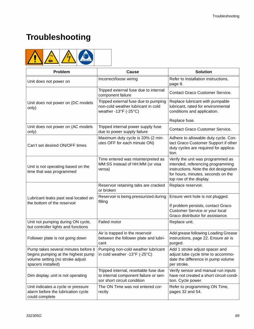
Problem Cause Solution
Unit does not power onIncorrect/loose wiring Refer to Installation instructions,
page 8.
Unit does not power on (DC models only)
Tripped external fuse due to internal component failure
Contact Graco Customer Service.
Tripped external fuse due to pumping non-cold weather lubricant in cold weather -13°F (-25°C)
Replace lubricant with pumpable lubricant, rated for environmental conditions and application.
Replace fuse.
Unit does not power on (AC models only)
Tripped internal power supply fuse due to power supply failure
Contact Graco Customer Service.
Can’t set desired ON/OFF times
Maximum duty cycle is 33% (2 min-utes OFF for each minute ON)
Adhere to allowable duty cycle. Con-tact Graco Customer Support if other duty cycles are required for applica-tion.
Unit is not operating based on the time that was programmed
Time entered was misinterpreted as MM:SS instead of HH:MM (or visa versa)
Verify the unit was programmed as intended, referencing programming instructions. Note the dot designation for hours, minutes, seconds on the top row of the display.
Lubricant leaks past seal located on the bottom of the reservoir
Reservoir retaining tabs are cracked or broken
Replace reservoir.
Reservoir is being pressurized during filling
Ensure vent hole is not plugged.
If problem persists, contact Graco Customer Service or your local Graco distributor for assistance.
Unit not pumping during ON cycle, but controller lights and functions
Failed motor Replace unit.
Follower plate is not going down Air is trapped in the reservoir between the follower plate and lubri-cant
Add grease following Loading Grease instructions, page 22. Ensure air is purged.
Pump takes several minutes before it begins pumping at the highest pump volume setting (no stroke adjust spacers installed)
Pumping non-cold weather lubricant in cold weather -13°F (-25°C)
Add 1 stroke adjust spacer and adjust lube cycle time to accommo-date the difference in pump volume per stroke.
Dim display, unit is not operatingTripped internal, resettable fuse due to internal component failure or sen-sor short circuit condition
Verify sensor and manual run inputs have not created a short circuit condi-tion. Cycle power.
Unit indicates a cycle or pressure alarm before the lubrication cycle could complete
The ON Time was not entered cor-rectly
Refer to programming ON Time, pages 32 and 54.
Troubleshooting
70 332305G
In an Injector System without sensor feedback, unit does not vent properly
Vent valve time needs to be config-ured
Refer to Advanced Programming to set ON Time, page 46.
Display acts erraticallyFaulty cycle/pressure wiring connec-tion to unit
Unplug cycle/pressure cables from G3. Plug cables in one at a time to identify the faulty connection.
USB Error 00 Flash drive was removed during operation
Keep the flash drive plugged in until the unit has completed the operation.
USB Error 07
Flash drive unable to mount (initial-ize)
• Unplug the flash drive and re-install.
• Cycle power and re-install the flash drive.
• Retry using a different flash drive.
If any of the above do not rectify the error, contact Graco Customer Ser-vice.
USB Error 11
Pump program setting file not found Verify that the pump program setting folder structure and file are stored correctly on the flash drive. See Stor-ing Pump Program Settings to the Flash Drive, page 38 for instructions.
USB Error 12
Pump program settings directory not found.
Verify that the pump program setting folder structure and file are stored correctly on the flash drive. See Stor-ing Pump Program Settings to the Flash Drive, page 38 for instructions.
USB Error 13
Bad pump program settings file The pump programs settings file is corrupt. Restore file to the flash drive. See Storing Pump Program Settings to the Flash Drive, page 38 for instructions.
All other USB errors
The following operations can be attempted if another error occurs using the USB.
• Unplug the flash drive and rein-stall.
• Cycle power and re-install the flash drive.
• Retry using a different flash drive.
If any of the above do not rectify the error, contact Graco Customer Ser-vice.
Problem Cause Solution
Maintenance
332305G 71
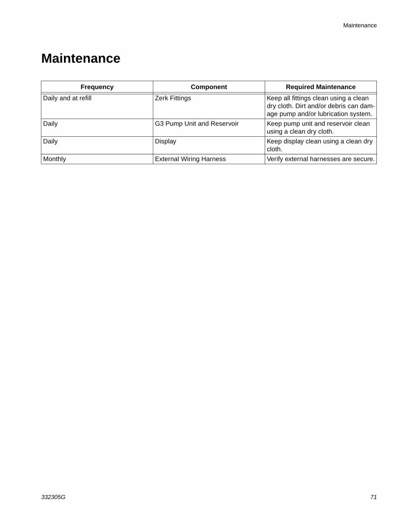
Maintenance
Frequency Component Required Maintenance
Daily and at refill Zerk Fittings Keep all fittings clean using a clean dry cloth. Dirt and/or debris can dam-age pump and/or lubrication system.
Daily G3 Pump Unit and Reservoir Keep pump unit and reservoir clean using a clean dry cloth.
Daily Display Keep display clean using a clean dry cloth.
Monthly External Wiring Harness Verify external harnesses are secure.
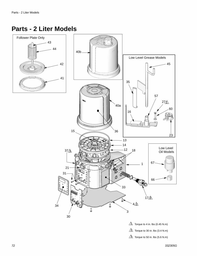
Parts - 2 Liter Models
72 332305G
Parts - 2 Liter Models
40a
44
14
1
42
13
18
17
34
36
33
37
41
21
30
15
4
3
31
Follower Plate Only43
Torque to 4 in. lbs (0.45 N.m)1
Torque to 30 in. lbs (3.4 N.m)2
Torque to 50 in. lbs (5.6 N.m)3
2
3
40b
3
45
35
27
23
1660
57
Low Level Grease Models
Low Level
66
67
1
12Oil Models
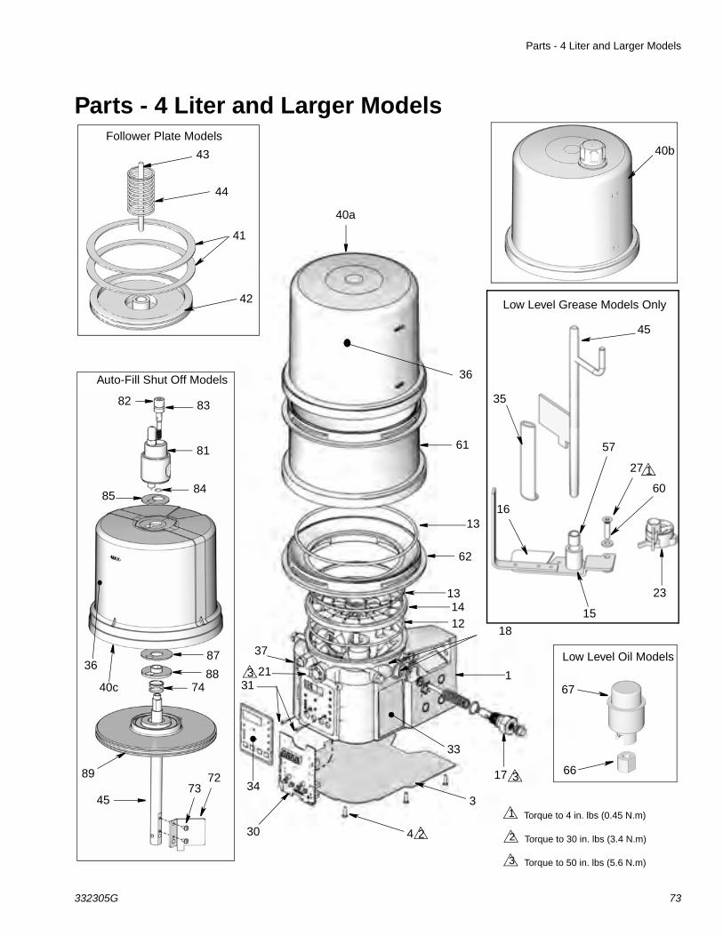
Parts - 4 Liter and Larger Models
332305G 73
Parts - 4 Liter and Larger Models
40a
44
35
14
1
41
13
18
1734
16
36
33
37
42
21
30
15
4
3
31
Follower Plate Models
43
Torque to 4 in. lbs (0.45 N.m)1
Torque to 30 in. lbs (3.4 N.m)2
Torque to 50 in. lbs (5.6 N.m)3
2
3
61
62
40b
3
27 1
45
60
23
57
Low Level Grease Models Only
67
66
Low Level Oil Models
12
13
Auto-Fill Shut Off Models
82 83
81
8485
40c
87
8874
36
89
4573
72
Parts
74 332305G
PartsRef Part Description Qty
1 BASE, three pump housing 1
3 278142 COVER, bottom, with seal 1
4 115477 SCREW, mach, torx pan hd 9
12 127079RECT-RING, included in Kit 571042, 571069, 571179
1
13 124396O-RING, 258, included in Kit 571042, 571044, 571045, 571069, 571179
2
14 PLATE, ricer 1
15 BEARING, ball 1
16
PADDLE, stirring, 2 Liter models without follower plate, included in Kit 571044
1
PADDLE, stirring, 4 Liter models and larger without follower plate
1
PADDLE, stirring, 2 Liter models with follower plate, included in Kit 571045
1
PADDLE, stirring, 4Liter models and larger with follower plate
1
17PUMP, element, included in Kit 571041
1
18 16F368SPACER, stroke adjust, included in Kit 571041
2
21 278145 PLUG, pump, 3/4-16 2
23 278136 PADDLE, low level 1
27 123025 SCREW, M6 1
30‡
258697 BOARD, circuit, Max, models 1
‡ 262463 BOARD, circuit, Max, DMS™ models
1
31 119228 SCREW, machine, flat head 2
33 16A579 LABEL, safety 1
34 16A073 LABEL, overlay 1
35
WIPER, stirring, models without fol-lower plate, included in Kit 571044
1
WIPER, stirring, models with fol-lower plate, included in Kit 571045
1
36 LABEL, brand 1
37 123741 FITTING, Zerk, grease 1
40a 24E984RESERVOIR, 2 liter, grease, included in Kit 571042, 571069
1
40b 16G021RESERVOIR, 2 liter, oil, included in Kit 571179
1
40a 24B702RESERVOIR, 4 liter, grease, included in Kit 571183
1
40b 16G020RESERVOIR, 4 Liter, oil, included in kit 571182
1
40c 17F484 RESERVOIR, 4 Liter, G3 AFSO 1
41278139 SEAL, follower plate, 2 liter models 1
16F472 SEAL, follower plate, 4 liter models 2
42 PLATE, follower 1
43 ROD, follower plate 1
44 SPRING, compression 1
45† 24D838 BAFFLE, low level, 2 liter models 1
† 24E246 BAFFLE, low level, 4 liter models 1
† 24F836 BAFFLE, low level, 8 liter models 1
† 24F923 BAFFLE, low level, 12 liter models 1
† 24F924 BAFFLE, low level, 16 liter models 1
57 117156 BEARING, sleeve 1
58 196548 LABEL 1
60 16D984 WASHER, low level models 2
61
RESERVOIR, mid-section (see quantity by size / model below)
8 Liter models 1
12 Liter models 2
16 Liter models 3
62 ADAPTER, reservoir 1
66 126417 NUT, oil 1
67 24N806 FLOAT, oil 1
Ref Part Description Qty
Parts
332305G 75
Replacement Danger and Warning labels, tags and cards are available at no cost.
Also order Ref 27, Part No. 123025 and Ref 60, Part No. 16D984
‡ Also order Ref 31, Part No. 119228 and Ref 34, Part No. 16A073
† Also order Ref. 57, Part No. 117156 when ordering this part.
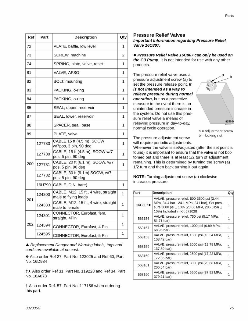
Pressure Relief Valves Important Information regarding Pressure Relief Valve 16C807.
Pressure Relief Valve 16C807 can only be used on the G3 Pump. It is not intended for use with any other products.
The pressure relief valve uses a pressure adjustment screw (a) to set the pressure release point. It is not intended as a way to relieve pressure during normal operation, but as a protective measure in the event there is an unintended pressure increase in the system. Do not use this pres-sure relief valve a means of relieving pressure in day-to-day, normal cycle operation.
The pressure adjustment screw will require periodic adjustments. Whenever the valve is set/adjusted (after the set point is found) it is important to ensure that the valve is not bot-tomed out and there is at least 1/2 turn of adjustment remaining. This is determined by turning the screw (a) 1/2 turn and then back turning it out again.
NOTE: Turning adjustment screw (a) clockwise increases pressure.
72 PLATE, baffle, low level 1
73 SCREW, machine 2
74 SPRING, plate, valve, reset 1
81 VALVE, AFSO 1
82 BOLT, mounting 1
83 PACKING, o-ring 1
84 PACKING, o-ring 1
85 SEAL, upper, reservoir 1
87 SEAL, lower, reservoir 1
88 SPACER, seal, base 1
89 PLATE, valve 1
200
127783CABLE,15 ft (4.5 m), SOOW w/7pos, 3 pin, 90 deg
1
127780CABLE, 15 ft (4.5 m), SOOW w/7 pos, 5 pin, 90 deg
1
127781CABLE, 20 ft (6.1 m), SOOW, w/7 pos, 5 pin, 90 deg
1
127782CABLE, 30 ft (9.1m) SOOW, w/7 pos, 5 pin, 90 deg
16U790 CABLE, DIN, bare) 1
201124300
CABLE, M12, 15 ft., 4 wire, straight male to flying leads
1
124333CABLE, M12, 15 ft., 4 wire, straight male to female
1
202
124301CONNECTOR, Eurofast, fem, straight, 4Pin
1
124594 CONNECTOR, Eurofast, 4 Pin 1
124595 CONNECTOR, Eurofast, 5 Pin 1
Ref Part Description Qty
Part Description Qty
16C807
VALVE, pressure relief, 500-3500 psi (3.44 MPa, 34.4 bar - 24.1 MPa, 241 bar), Set pres-sure 3000 psi + 10% (20.68 MPa, 206.8 bar + 10%) Included in Kit 571028
1
563156VALVE, pressure relief, 750 psi (5.17 MPa, 51.71 bar)
1
563157VALVE, pressure relief, 1000 psi (6.89 MPa, 68.95 bar)
1
563158VALVE, pressure relief, 1500 psi (10.34 MPa, 103.42 bar)
1
563159VALVE, pressure relief, 2000 psi (13.78 MPa, 137.89 bar)
1
563160VALVE, pressure relief, 2500 psi (17.23 MPa, 172.36 bar)
1
563161VALVE, pressure relief, 3000 psi (20.68 MPa, 206.84 bar)
1
563190VALVE, pressure relief, 5500 psi (37.92 MPa, 379.21 bar)
1
a
ti15644
b
a = adjustment screwb = locking nut
Parts
76 332305G
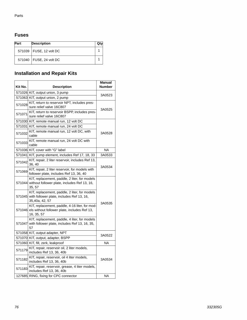
Fuses
Installation and Repair Kits
Part Description Qty
571039 FUSE, 12 volt DC 1
571040 FUSE, 24 volt DC 1
Kit No. DescriptionManual Number
571026 KIT, output union, 3 pump3A0523
571063 KIT, output union, 2 pump
571028KIT, return to reservoir NPT, includes pres-sure relief valve 16C807
3A0525571071
KIT, return to reservoir BSPP, includes pres-sure relief valve 16C807
571030 KIT, remote manual run, 12 volt DC
3A0528
571031 KIT, remote manual run, 24 volt DC
571032KIT, remote manual run, 12 volt DC, with cable
571033KIT, remote manual run, 24 volt DC with cable
571036 KIT, cover with “G” label NA
571041 KIT, pump element, includes Ref 17, 18, 33 3A0533
571042KIT, repair, 2 liter reservoir, includes Ref 13, 36, 40
3A0534571069
KIT, repair, 2 liter reservoir, for models with follower plate, includes Ref 13, 36, 40
571044KIT, replacement, paddle, 2 liter, for models without follower plate, includes Ref 13, 16, 35, 57
3A0535
571045KIT, replacement, paddle, 2 liter, for models with follower plate, includes Ref 13, 16, 35,40a, 42, 57
571046KIT, replacement, paddle, 4-16 liter, for mod-els without follower plate, includes Ref 13, 16, 35, 57
571047KIT, replacement, paddle, 4 liter, for models with follower plate, includes Ref 13, 16, 35, 57
571058 KIT, output adapter, NPT3A0522
571070 KIT, output, adapter, BSPP
571060 KIT, fill, zerk, leakproof NA
571179KIT, repair, reservoir oil, 2 liter models, includes Ref 13, 36, 40b
3A0534571182KIT, repair, reservoir, oil 4 liter models, includes Ref 13, 36, 40b
571183KIT, repair, reservoir, grease, 4 liter models, includes Ref 13, 36, 40b
127685 RING, fixing for CPC connector NA
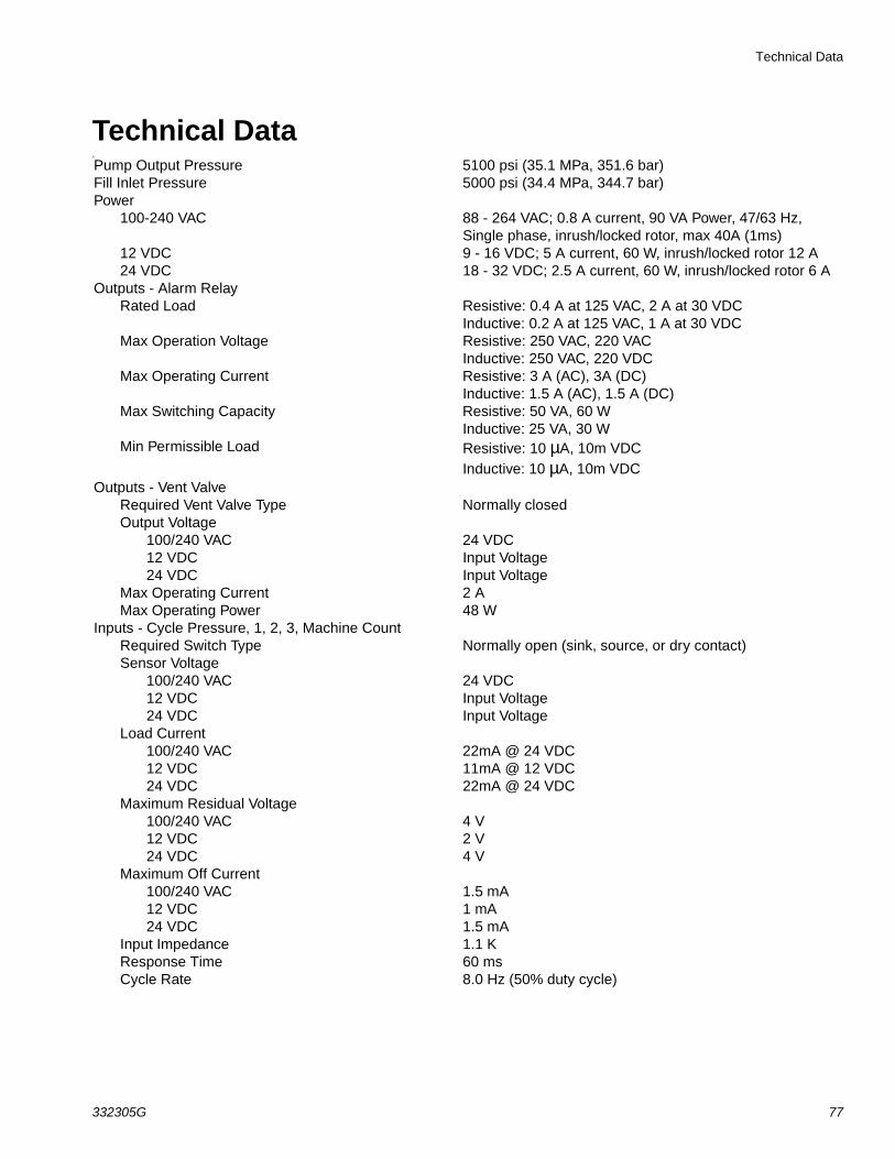
Technical Data
332305G 77
Technical DataA
Pump Output Pressure 5100 psi (35.1 MPa, 351.6 bar)Fill Inlet Pressure 5000 psi (34.4 MPa, 344.7 bar)Power
100-240 VAC 88 - 264 VAC; 0.8 A current, 90 VA Power, 47/63 Hz, Single phase, inrush/locked rotor, max 40A (1ms)
12 VDC 9 - 16 VDC; 5 A current, 60 W, inrush/locked rotor 12 A24 VDC 18 - 32 VDC; 2.5 A current, 60 W, inrush/locked rotor 6 A
Outputs - Alarm RelayRated Load Resistive: 0.4 A at 125 VAC, 2 A at 30 VDC
Inductive: 0.2 A at 125 VAC, 1 A at 30 VDCMax Operation Voltage Resistive: 250 VAC, 220 VAC
Inductive: 250 VAC, 220 VDCMax Operating Current Resistive: 3 A (AC), 3A (DC)
Inductive: 1.5 A (AC), 1.5 A (DC)Max Switching Capacity Resistive: 50 VA, 60 W
Inductive: 25 VA, 30 WMin Permissible Load Resistive: 10 µA, 10m VDC
Inductive: 10 µA, 10m VDCOutputs - Vent Valve
Required Vent Valve Type Normally closedOutput Voltage
100/240 VAC 24 VDC12 VDC Input Voltage24 VDC Input Voltage
Max Operating Current 2 AMax Operating Power 48 W
Inputs - Cycle Pressure, 1, 2, 3, Machine CountRequired Switch Type Normally open (sink, source, or dry contact)Sensor Voltage
100/240 VAC 24 VDC12 VDC Input Voltage24 VDC Input Voltage
Load Current100/240 VAC 22mA @ 24 VDC12 VDC 11mA @ 12 VDC24 VDC 22mA @ 24 VDC
Maximum Residual Voltage100/240 VAC 4 V12 VDC 2 V24 VDC 4 V
Maximum Off Current100/240 VAC 1.5 mA12 VDC 1 mA24 VDC 1.5 mA
Input Impedance 1.1 KResponse Time 60 msCycle Rate 8.0 Hz (50% duty cycle)
Technical Data
78 332305G
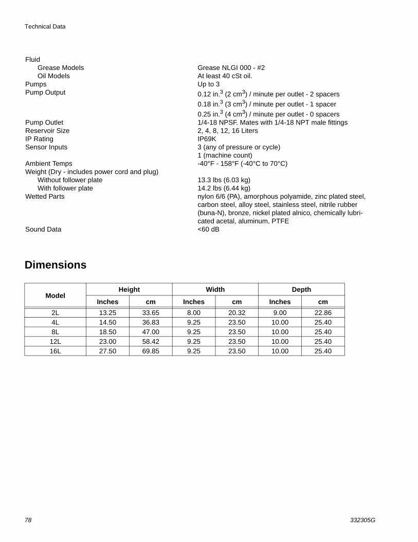
Dimensions
FluidGrease Models Grease NLGI 000 - #2Oil Models At least 40 cSt oil.
Pumps Up to 3Pump Output 0.12 in.3 (2 cm3) / minute per outlet - 2 spacers
0.18 in.3 (3 cm3) / minute per outlet - 1 spacer
0.25 in.3 (4 cm3) / minute per outlet - 0 spacersPump Outlet 1/4-18 NPSF. Mates with 1/4-18 NPT male fittingsReservoir Size 2, 4, 8, 12, 16 LitersIP Rating IP69KSensor Inputs 3 (any of pressure or cycle)
1 (machine count)Ambient Temps -40°F - 158°F (-40°C to 70°C)Weight (Dry - includes power cord and plug)
Without follower plate 13.3 lbs (6.03 kg)With follower plate 14.2 lbs (6.44 kg)
Wetted Parts nylon 6/6 (PA), amorphous polyamide, zinc plated steel, carbon steel, alloy steel, stainless steel, nitrile rubber (buna-N), bronze, nickel plated alnico, chemically lubri-cated acetal, aluminum, PTFE
Sound Data <60 dB
ModelHeight Width Depth
Inches cm Inches cm Inches cm
2L 13.25 33.65 8.00 20.32 9.00 22.864L 14.50 36.83 9.25 23.50 10.00 25.408L 18.50 47.00 9.25 23.50 10.00 25.4012L 23.00 58.42 9.25 23.50 10.00 25.4016L 27.50 69.85 9.25 23.50 10.00 25.40
Technical Data
332305G 79
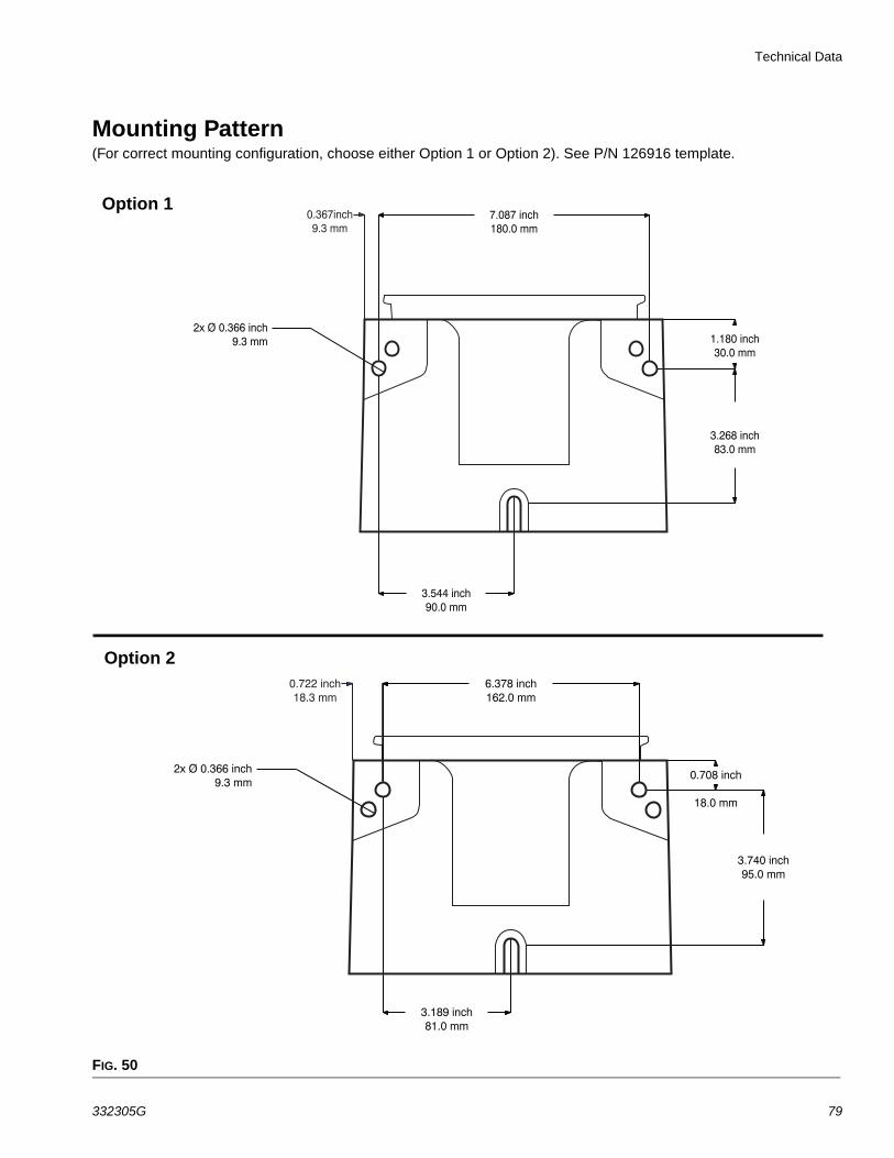
Mounting Pattern (For correct mounting configuration, choose either Option 1 or Option 2). See P/N 126916 template.
FIG. 50
0.367inch9.3 mm
2x Ø 0.366 inch9.3 mm
3.544 inch90.0 mm
7.087 inch180.0 mm
1.180 inch30.0 mm
3.268 inch83.0 mm
0.722 inch18.3 mm
2x Ø 0.366 inch9.3 mm
3.189 inch81.0 mm
6.378 inch162.0 mm
3.740 inch95.0 mm
0.708 inch
18.0 mm
Option 1
Option 2
All written and visual data contained in this document reflects the latest product information available at the time of publication. Graco reserves the right to make changes at any time without notice.
Original instructions. This manual contains English. MM 332305Graco Headquarters: Minneapolis
International Offices: Belgium, China, Japan, Korea
GRACO INC. AND SUBSIDIARIES • P.O. BOX 1441 • MINNEAPOLIS MN 55440-1441 • USACopyright 2013, Graco Inc. All Graco manufacturing locations are registered to ISO 9001.
www.graco.comMarch 2017
Graco Standard WarrantyGraco warrants all equipment referenced in this document which is manufactured by Graco and bearing its name to be free from defects in material and workmanship on the date of sale to the original purchaser for use. With the exception of any special, extended, or limited warranty published by Graco, Graco will, for a period of twelve months from the date of sale, repair or replace any part of the equipment determined by Graco to be defective. This warranty applies only when the equipment is installed, operated and maintained in accordance with Graco’s written recommendations.
This warranty does not cover, and Graco shall not be liable for general wear and tear, or any malfunction, damage or wear caused by faulty installation, misapplication, abrasion, corrosion, inadequate or improper maintenance, negligence, accident, tampering, or substitution of non-Graco component parts. Nor shall Graco be liable for malfunction, damage or wear caused by the incompatibility of Graco equipment with structures, accessories, equipment or materials not supplied by Graco, or the improper design, manufacture, installation, operation or maintenance of structures, accessories, equipment or materials not supplied by Graco.
This warranty is conditioned upon the prepaid return of the equipment claimed to be defective to an authorized Graco distributor for verification of the claimed defect. If the claimed defect is verified, Graco will repair or replace free of charge any defective parts. The equipment will be returned to the original purchaser transportation prepaid. If inspection of the equipment does not disclose any defect in material or workmanship, repairs will be made at a reasonable charge, which charges may include the costs of parts, labor, and transportation.
THIS WARRANTY IS EXCLUSIVE, AND IS IN LIEU OF ANY OTHER WARRANTIES, EXPRESS OR IMPLIED, INCLUDING BUT NOT LIMITED TO WARRANTY OF MERCHANTABILITY OR WARRANTY OF FITNESS FOR A PARTICULAR PURPOSE.
Graco’s sole obligation and buyer’s sole remedy for any breach of warranty shall be as set forth above. The buyer agrees that no other remedy (including, but not limited to, incidental or consequential damages for lost profits, lost sales, injury to person or property, or any other incidental or consequential loss) shall be available. Any action for breach of warranty must be brought within two (2) years of the date of sale.
GRACO MAKES NO WARRANTY, AND DISCLAIMS ALL IMPLIED WARRANTIES OF MERCHANTABILITY AND FITNESS FOR A PARTICULAR PURPOSE, IN CONNECTION WITH ACCESSORIES, EQUIPMENT, MATERIALS OR COMPONENTS SOLD BUT NOT MANUFACTURED BY GRACO. These items sold, but not manufactured by Graco (such as electric motors, switches, hose, etc.), are subject to the warranty, if any, of their manufacturer. Graco will provide purchaser with reasonable assistance in making any claim for breach of these warranties.
In no event will Graco be liable for indirect, incidental, special or consequential damages resulting from Graco supplying equipment hereunder, or the furnishing, performance, or use of any products or other goods sold hereto, whether due to a breach of contract, breach of warranty, the negligence of Graco, or otherwise.
FOR GRACO CANADA CUSTOMERSThe Parties acknowledge that they have required that the present document, as well as all documents, notices and legal proceedings entered into, given or instituted pursuant hereto or relating directly or indirectly hereto, be drawn up in English. Les parties reconnaissent avoir convenu que la rédaction du présente document sera en Anglais, ainsi que tous documents, avis et procédures judiciaires exécutés, donnés ou intentés, à la suite de ou en rapport, directement ou indirectement, avec les procédures concernées.
Graco Information
For the latest information about Graco products, visit www.graco.com.
TO PLACE AN ORDER, contact your Graco distributor or call to identify the nearest distributor.Phone: 612-623-6928 or Toll Free: 1-800-533-9655, Fax: 612-378-3590


![CYCLE PRESSURE - paintball-team-roterbaron.depaintball-team-roterbaron.de/technik/dye/Dye-DMC-Manual.pdf · CYCLE PRESSURE [75PSI] MAX RATE OF ... TROUBLE SHOOTING GUIDE ... residual](https://img.pdfslide.us/doc/110x75/5b8455c07f8b9a784a8c156c/cycle-pressure-paintball-team-cycle-pressure-75psi-max-rate-of-trouble.jpg)