Embed Size (px)
Citation preview
SWRU270C
Page 16 of 30
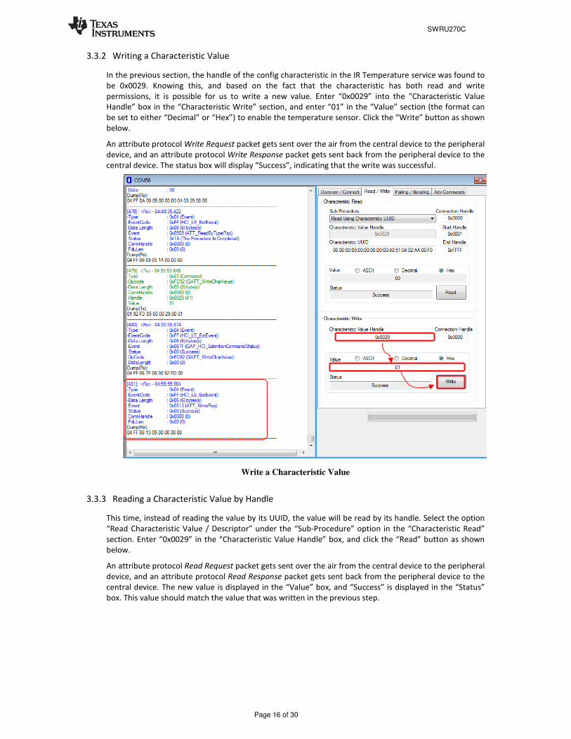
3.3.2 Writing a Characteristic Value
In the previous section, the handle of the config characteristic in the IR Temperature service was found to
be 0x0029. Knowing this, and based on the fact that the characteristic has both read and write
permissions, it is possible for us to write a new value. Enter “0x0029” into the “Characteristic Value
Handle” box in the “Characteristic Write” section, and enter “01” in the “Value” section (the format can
be set to either “Decimal” or “Hex”) to enable the temperature sensor. Click the “Write” button as shown
below.
An attribute protocol Write Request packet gets sent over the air from the central device to the peripheral
device, and an attribute protocol Write Response packet gets sent back from the peripheral device to the
central device. The status box will display “Success”, indicating that the write was successful.
Write a Characteristic Value
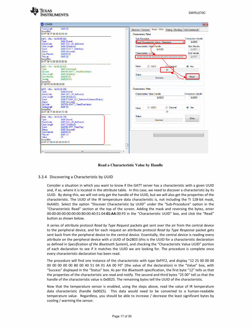
3.3.3 Reading a Characteristic Value by Handle
This time, instead of reading the value by its UUID, the value will be read by its handle. Select the option
“Read Characteristic Value / Descriptor” under the “Sub-Procedure” option in the “Characteristic Read”
section. Enter “0x0029” in the “Characteristic Value Handle” box, and click the “Read” button as shown
below.
An attribute protocol Read Request packet gets sent over the air from the central device to the peripheral
device, and an attribute protocol Read Response packet gets sent back from the peripheral device to the
central device. The new value is displayed in the “Value” box, and “Success” is displayed in the “Status”
box. This value should match the value that was written in the previous step.
SWRU270C
Page 17 of 30
Read a Characteristic Value by Handle
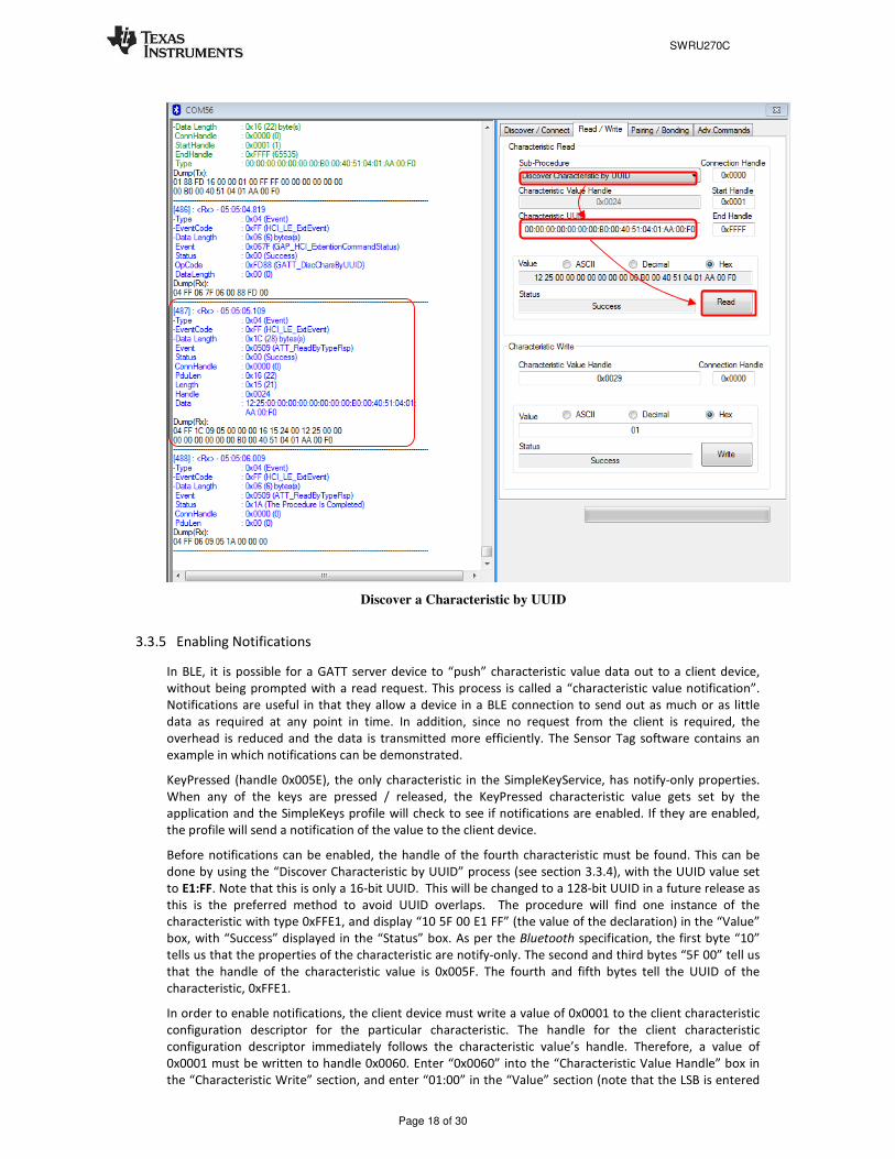
3.3.4 Discovering a Characteristic by UUID
Consider a situation in which you want to know if the GATT server has a characteristic with a given UUID
and, if so, where it is located in the attribute table. In this case, we need to discover a characteristic by its
UUID. By doing this, we will not only get the handle of the UUID, but we will also get the properties of the
characteristic. The UUID of the IR temperature data characteristic is, not including the TI 128-bit mask,
0xAA01. Select the option “Discover Characteristic by UUID” under the “Sub-Procedure” option in the
“Characteristic Read” section at the top of the screen. Adding the mask and reversing the bytes, enter
00:00:00:00:00:00:00:B0:00:40:51:04:01:AA:00:F0 in the “Characteristic UUID” box, and click the “Read”
button as shown below.
A series of attribute protocol Read by Type Request packets get sent over the air from the central device
to the peripheral device, and for each request an attribute protocol Read by Type Response packet gets
sent back from the peripheral device to the central device. Essentially, the central device is reading every
attribute on the peripheral device with a UUID of 0x2803 (this is the UUID for a characteristic declaration
as defined in Specification of the Bluetooth System), and checking the “Characteristic Value UUID” portion
of each declaration to see if it matches the UUID we are looking for. The procedure is complete once
every characteristic declaration has been read.
The procedure will find one instance of the characteristic with type 0xFFF2, and display “12 25 00 00 00
00 00 00 00 00 B0 00 40 51 04 01 AA 00 F0” (the value of the declaration) in the “Value” box, with
“Success” displayed in the “Status” box. As per the Bluetooth specification, the first byte “12” tells us that
the properties of the characteristic are read and notify. The second and third bytes “25 00” tell us that the
handle of the characteristic value is 0x0025. The remaining bytes tell the UUID of the characteristic.
Now that the temperature sensor is enabled, using the steps above, read the value of IR temperature
data characteristic (handle 0x0025). This data would need to be converted to a human-readable
temperature value. Regardless, you should be able to increase / decrease the least significant bytes by
cooling / warming the sensor.
SWRU270C
Page 18 of 30
Discover a Characteristic by UUID
3.3.5 Enabling Notifications
In BLE, it is possible for a GATT server device to “push” characteristic value data out to a client device,
without being prompted with a read request. This process is called a “characteristic value notification”.
Notifications are useful in that they allow a device in a BLE connection to send out as much or as little
data as required at any point in time. In addition, since no request from the client is required, the
overhead is reduced and the data is transmitted more efficiently. The Sensor Tag software contains an
example in which notifications can be demonstrated.
KeyPressed (handle 0x005E), the only characteristic in the SimpleKeyService, has notify-only properties.
When any of the keys are pressed / released, the KeyPressed characteristic value gets set by the
application and the SimpleKeys profile will check to see if notifications are enabled. If they are enabled,
the profile will send a notification of the value to the client device.
Before notifications can be enabled, the handle of the fourth characteristic must be found. This can be
done by using the “Discover Characteristic by UUID” process (see section 3.3.4), with the UUID value set
to E1:FF. Note that this is only a 16-bit UUID. This will be changed to a 128-bit UUID in a future release as
this is the preferred method to avoid UUID overlaps. The procedure will find one instance of the
characteristic with type 0xFFE1, and display “10 5F 00 E1 FF” (the value of the declaration) in the “Value”
box, with “Success” displayed in the “Status” box. As per the Bluetooth specification, the first byte “10”
tells us that the properties of the characteristic are notify-only. The second and third bytes “5F 00” tell us
that the handle of the characteristic value is 0x005F. The fourth and fifth bytes tell the UUID of the
characteristic, 0xFFE1.
In order to enable notifications, the client device must write a value of 0x0001 to the client characteristic
configuration descriptor for the particular characteristic. The handle for the client characteristic
configuration descriptor immediately follows the characteristic value’s handle. Therefore, a value of
0x0001 must be written to handle 0x0060. Enter “0x0060” into the “Characteristic Value Handle” box in
the “Characteristic Write” section, and enter “01:00” in the “Value” section (note that the LSB is entered

SWRU270C
Page 19 of 30
first, and the MSB is entered last and all client characteristic configurations are two-byte values). Click the
“Write Value” button. The status box will display “Success”, indicating that the write was successful.
Every time a key is pressed or released, an attribute protocol Handle Value Notification packet gets sent
from the peripheral device to the central device. With each notification, the value of the characteristic at
handle is displayed in the log window.
Note that it is also possible to send indications in the same manner if the characteristic has indication
property. In this case, the only difference is that the GATT client must respond to the indication to verify
that it received the data.
Figure 18 BTool, Enable Notifications
It is important to note that the simple GATT profile included with the BLE development kit does not
conform to any standard profile specification available from the Bluetooth SIG. The profile, including
the GATT characteristic definition, the UUID values, and the functional behavior, was developed by
Texas Instruments for use with the CC2540DK or CC2542EMK development kit, and is intended as a
demonstration of the capabilities of the Bluetooth low energy protocol.
3.4 Using BLE Security
BTool also includes the ability to make use of security features in BLE, including encryption,
authentication, and bonding.
3.4.1 Encrypting the Connection
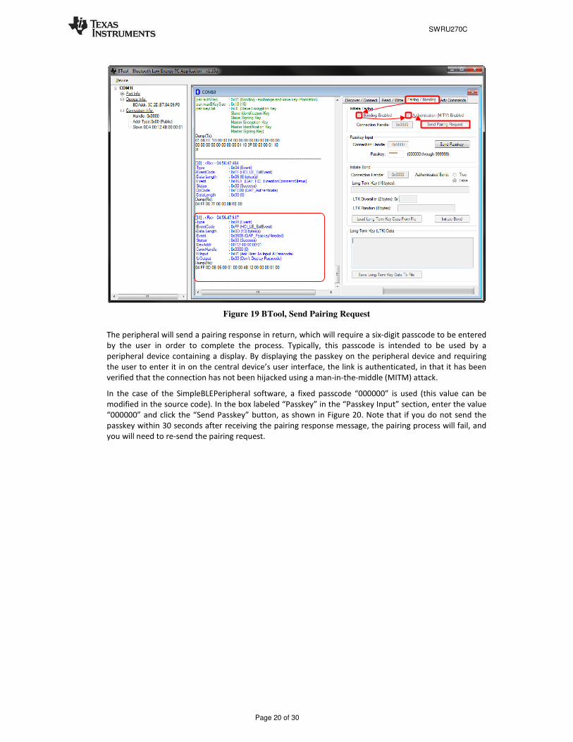
To encrypt the link, the pairing process must be initiated. Click on the “Pairing / Bonding” tab in BTool. In
the “Initiate Pairing” section at the top of the screen, check the boxes labeled “Bonding Enabled” and
“Authentication (MITM) Enabled”, and click the button “Send Pairing Request”, as shown in Figure 19.
This will send the request to the peripheral device.
+1
SWRU270C
Page 20 of 30
Figure 19 BTool, Send Pairing Request
The peripheral will send a pairing response in return, which will require a six-digit passcode to be entered
by the user in order to complete the process. Typically, this passcode is intended to be used by a
peripheral device containing a display. By displaying the passkey on the peripheral device and requiring
the user to enter it in on the central device’s user interface, the link is authenticated, in that it has been
verified that the connection has not been hijacked using a man-in-the-middle (MITM) attack.
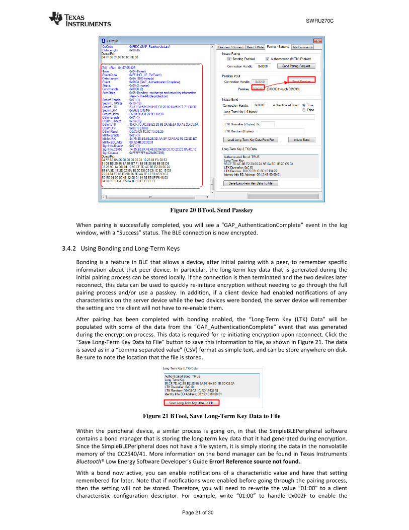
In the case of the SimpleBLEPeripheral software, a fixed passcode “000000” is used (this value can be
modified in the source code). In the box labeled “Passkey” in the “Passkey Input” section, enter the value
“000000” and click the “Send Passkey” button, as shown in Figure 20. Note that if you do not send the
passkey within 30 seconds after receiving the pairing response message, the pairing process will fail, and
you will need to re-send the pairing request.
SWRU270C
Page 21 of 30
Figure 20 BTool, Send Passkey
When pairing is successfully completed, you will see a “GAP_AuthenticationComplete” event in the log
window, with a “Success” status. The BLE connection is now encrypted.
3.4.2 Using Bonding and Long-Term Keys
Bonding is a feature in BLE that allows a device, after initial pairing with a peer, to remember specific
information about that peer device. In particular, the long-term key data that is generated during the
initial pairing process can be stored locally. If the connection is then terminated and the two devices later
reconnect, this data can be used to quickly re-initiate encryption without needing to go through the full
pairing process and/or use a passkey. In addition, if a client device had enabled notifications of any
characteristics on the server device while the two devices were bonded, the server device will remember
the setting and the client will not have to re-enable them.
After pairing has been completed with bonding enabled, the “Long-Term Key (LTK) Data” will be
populated with some of the data from the “GAP_AuthenticationComplete” event that was generated
during the encryption process. This data is required for re-initiating encryption upon reconnect. Click the
“Save Long-Term Key Data to File” button to save this information to file, as shown in Figure 21. The data
is saved as in a “comma separated value” (CSV) format as simple text, and can be store anywhere on disk.
Be sure to note the location that the file is stored.
Figure 21 BTool, Save Long-Term Key Data to File
Within the peripheral device, a similar process is going on, in that the SimpleBLEPeripheral software
contains a bond manager that is storing the long-term key data that it had generated during encryption.
Since the SimpleBLEPeripheral does not have a file system, it is simply storing the data in the nonvolatile
memory of the CC2540/41. More information on the bond manager can be found in Texas Instruments
Bluetooth® Low Energy Software Developer’s Guide Error! Reference source not found..
With a bond now active, you can enable notifications of a characteristic value and have that setting
remembered for later. Note that if notifications were enabled before going through the pairing process,
then the setting will not be stored. Therefore, you will need to re-write the value “01:00” to a client
characteristic configuration descriptor. For example, write “01:00” to handle 0x002F to enable the

SWRU270C
Page 22 of 30
periodic notifications, as was done in section 3.3.5. You should now be receiving a notification once every
five seconds. Because the devices are paired with bonding enabled, the bond manager in the
SimpleBLEPeripheral software will store the client characteristic configuration descriptor data in
nonvolatile memory.
To verify that bonding worked, you will need to disconnect and re-connect. Click on the “Discover /
Connect” tab and click the “Terminate” button at the bottom of the screen to disconnect from the
peripheral device, as shown in Figure 22. The message window will show a “GAP_TerminateLink” event
with “Success” status. In addition, the connection information in the upper-left corner of the screen will
disappear.
Figure 22 BTool, Terminate Link
At a later time, re-connect with the peripheral device following the procedure in section 3.2.4. Once
connected, you will notice that the periodic notifications are no longer enabled. This is because the
Simple GATT profile will always reset the value of the client characteristic configuration descriptor back to
“00:00” if a connection is terminated or if the device resets.
To re-initiate encryption and re-enable the periodic notifications, return to the “Pairing / Bonding” tab. In
the “Initiate Bond” section, click the “Load Long-Term Key Data From File” button, and select the file in
which the data was previously stored. The data fields will get automatically populated from the data in
the file. Click the “Initiate Bond” button to re-enable encryption, as shown in Figure 23.

SWRU270C
Page 23 of 30
Figure 23 BTool, Re-initiate Encryption
A “GAP_BondComplete” event with “Success” status will be displayed in the message window. This
indicates that the link has been re-encrypted, which can be verified by reading the fifth characteristic
value in the SimpleGATTProfile at handle 0x0032. You will also now be receiving periodic notifications of
the fourth characteristic value, as the client characteristic configuration descriptor value of the
characteristic has been restored. Any changes to the client characteristic configuration descriptor value
(i.e. turning off notifications) will be saved to nonvolatile memory and remembered for next time that
encryption is initiated using the long-term key.
3.5 Additional Sample Applications
In addition to the Sensor tagDemo application, the BLE software development kit includes project and
source code files for several additional applications and profiles, including:
• Blood Pressure Sensor- with simulated measurements
• Emulated Keyboard- press the two buttons on the sensor tag to simulate keyboard presses
• Heart Rate Sensor- with simulated measurements
• Health Thermometer- with simulated measurements
• Glucose Sensor – with simulated measurements
• SimpleBLEPeripheral - with proprietary profile which implements all various types of permissions
More information on these projects can be found in the Texas Instruments BLE Sample Applications Guide
Error! Reference source not found..

SWRU270C
Page 24 of 30
4. Programming / Debugging the CC2540 or CC2541
The CC Debugger included with the CC254XDK-MINI kit allows for debugging using IAR Embedded
Workbench for 8051, as well as for reading and writing hex files to the CC2540/41 flash memory using the
SmartRF Flash Programmer software. SmartRF Flash Programmer also has the capability to change the
IEEE address of the CC2540/41 device. The BLE software development kit includes hex files for both the
USB Dongle as well as the sensor tag. This section details the hardware setup when using the CC
Debugger, as well as information on using SmartRF Flash Programmer. Information on using IAR
Embedded Workbench for debugging can be found in the Texas Instruments Bluetooth® Low Energy
Software Developer’s Guide Error! Reference source not found..
4.1 Hardware Setup for Sensor tag
If the sensor tag is viewed with the LED on top and the coin cell battery holder at the bottom, then the set
of pins closer to the top are the ones that should be used for connecting to the debugger. Pin 1 is the pin
on the lower right side as shown in Figure 24.
Figure 24 CC2540 Sensor tag, Debug Connector
Connect the CC Debugger to the sensor tag as shown below. Be sure that the ribbon cable is oriented
properly, with the red stripe connected to pin 1 as shown in Figure 25.
Figure 25 CC2540 Sensor tag Connected to CC Debugger
Insert a coin cell battery in the sensor tag to supply power to the target. NB! Note the orientation of the
battery (+ up, - down). Next, connect the CC Debugger to the PC’s USB port and then to the sensor tag.
Note that the CC debugger will by default not supply any power, but it will sense the voltage on the target
(in this case the sensor tag) for proper level shifting of the debug signals. The status indicator LED on the
CC Debugger should turn on. If the LED is red, that means no CC2540/41 device was detected. If it is
green, then a CC2540/41 device has been detected. If the sensor tag is connected and the LED is red, try
pressing the reset button on the CC Debugger. This resets the debugger and re-checks for a CC2540/41
device. If the LED still does not turn green, re-check that all cables are securely connected. Also verify that
the CC Debugger has the latest firmware (see section 4.3).