Embed Size (px)
Citation preview
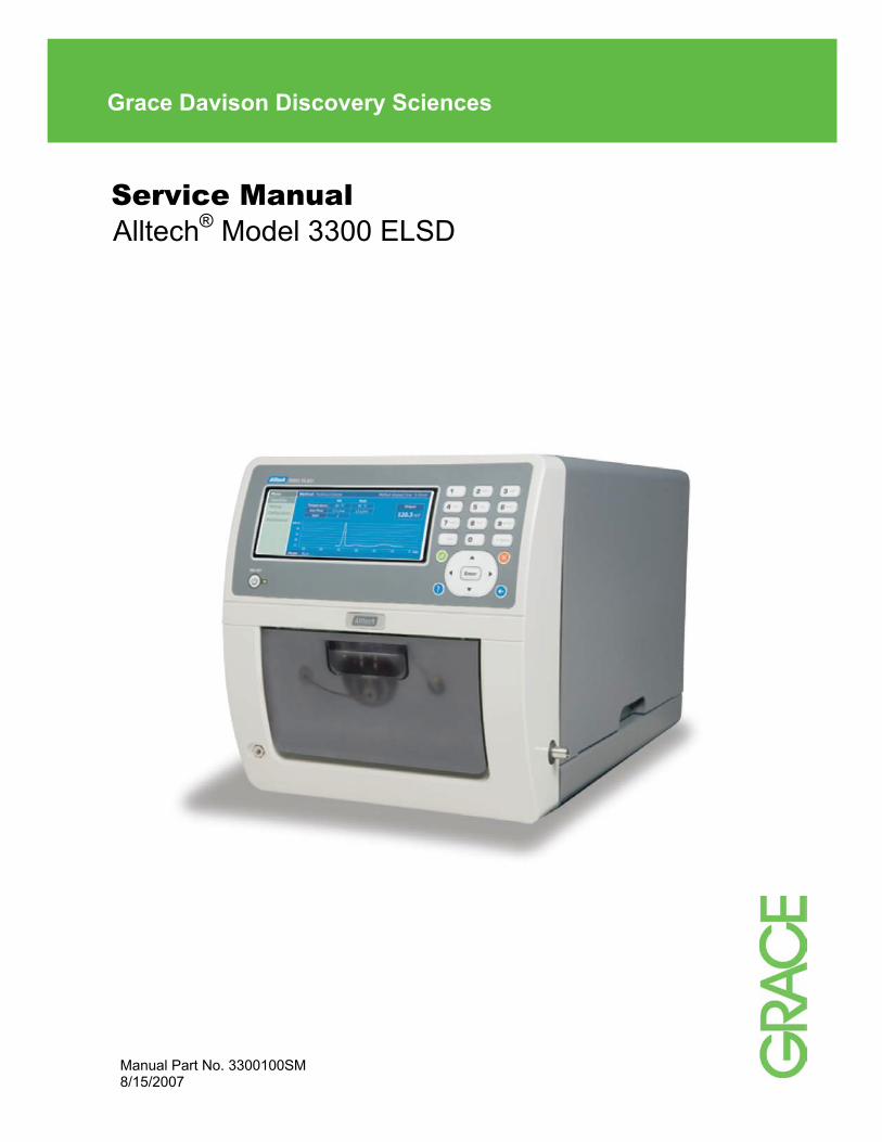
Service Manual Alltech® Model 3300 ELSD
Grace Davison Discovery Sciences
Manual Part No. 3300100SM 8/15/2007
ii
Important Safety Guidelines for the Model 3300 ELSD
Please read the following cautions and warning statements carefully before using the Model 3300 ELSD:
• Warning: The equipment must be used as specified by the manufacturer otherwise overall safety will be impaired.
• Warning: All service must be completed by qualified personnel only.
• Warning: Only use the power supply cord recommended by the manufacturer.
• Warning: Fire hazard, only use the same type and rated CERTIFIED fuse ( 250V 5A F).
• Warning: Shock hazard, disconnect power before replacing the fuse.
• Warning: Remove power cord from the power module to disconnect electrical power from the unit.
• Warning: Check the MSDS forms and dispense and dispose of all reagents in accordance with local and national regulations.
• Warning: Be sure to provide proper ventilation for all solvent vapors.
• Warning: Avoid open flames and sparks when using flammable solvents.
• Warning: If the unit is damaged and does not function properly, stop the unit safely and contact the manufacturer immediately.
• Warning: Class 3B LASER radiation inside can cause severe eye damage. Do not open or defeat interlocks. Avoid exposure to the beam.

i
Table of Contents 1. Introduction ......................................................................................................................... 4
1.1 About the Model 3300 ELSD ...................................................................................................................... 4 1.2 Principle of Operation ................................................................................................................................ 5
2. Installation ........................................................................................................................... 6 2.1 What You Will Need .................................................................................................................................... 6 2.2 Unpacking.................................................................................................................................................... 6 2.3 Controls and Features................................................................................................................................ 7
2.3.1 Front Panel....................................................................................................................................... 7 2.3.2 Back Panel ...................................................................................................................................... 8
2.4 Making Electrical and Fluid Connections................................................................................................. 9 3. Navigating the Software Interface.................................................................................... 10
3.1 Main Screen............................................................................................................................................... 10 3.2 Operation ................................................................................................................................................... 10
3.2.1 Mode ............................................................................................................................................... 10 3.2.2 Start/Stop Run ............................................................................................................................... 11 3.2.3 Lock/Unlock Detector.................................................................................................................... 11 3.2.4 Chart ............................................................................................................................................... 11
3.2.5 Autozero ......................................................................................................................................... 12
3.3 Method ....................................................................................................................................................... 12 3.3.1 New ................................................................................................................................................. 12 3.3.2 Open................................................................................................................................................ 13 3.3.3 Edit .................................................................................................................................................. 13 3.3.4 Delete.............................................................................................................................................. 14 3.3.5 Wizard............................................................................................................................................. 14
3.4 Configuration ............................................................................................................................................ 14 3.4.1 Alarm............................................................................................................................................... 14 3.4.2 Serial Number ................................................................................................................................ 15 3.4.3 Outputs........................................................................................................................................... 15 3.4.4 Display............................................................................................................................................ 15 3.4.5 Heaters............................................................................................................................................ 15 3.4.6 Date and Time ................................................................................................................................ 16 3.4.7 Language........................................................................................................................................ 16 3.4.8 Pressure Units ............................................................................................................................... 16 3.4.9 Network .......................................................................................................................................... 16 3.4.10 Timed Mode Changes ................................................................................................................... 16
ii
3.5 Maintenance .............................................................................................................................................. 17 3.5.1 Manual Control .............................................................................................................................. 17 3.5.2 Logs ................................................................................................................................................ 18 3.5.3 Tests ............................................................................................................................................... 18 3.5.4 Files................................................................................................................................................. 18 3.5.5 Service Tech .................................................................................................................................. 19 3.5.6 Calibration...................................................................................................................................... 19 3.5.7 About .............................................................................................................................................. 19 4. Routine Operation ............................................................................................................. 20
4.1 Safety ......................................................................................................................................................... 20 4.2 Operating Notes ........................................................................................................................................ 20 4.3 Selecting Initial Operating Conditions.................................................................................................... 20 4.4 Startup Sequence ..................................................................................................................................... 20 4.5 Shutdown Sequence................................................................................................................................. 21 4.6 Optimization Procedure ........................................................................................................................... 21
5. Maintenance....................................................................................................................... 22 5.1 Cleaning Mode .......................................................................................................................................... 22 5.2 Nebulizer Cleaning Procedure................................................................................................................. 22 5.3 Drift Tube Cleaning Procedure................................................................................................................ 23 5.4 Optics Cleaning Procedures.................................................................................................................... 24
5.4.1 Optics Block Cleaning Procedure ............................................................................................... 24 5.4.2 Laser Window Cleaning Procedure ............................................................................................. 25 5.4.3 Photodiode Cleaning Procedure.................................................................................................. 25 5.4.4 Pre-Amp Lens Assembly Cleaning Procedure........................................................................... 26
5.5 Fuse Replacement .................................................................................................................................... 30 6. Diagnostics and Troubleshooting ................................................................................... 31
6.1 Errors ......................................................................................................................................................... 31 6.2 Performing Diagnostic Tests................................................................................................................... 34
6.2.1 Nebulizer Gas Pressure Test........................................................................................................ 34 6.2.2 Gas Flow Test ................................................................................................................................ 35 6.2.3 Optics Test ..................................................................................................................................... 36 6.2.4 Optics Heating Test....................................................................................................................... 37 6.2.5 Heater Stability Test ...................................................................................................................... 38 6.2.6 Power Supply Test ........................................................................................................................ 39
6.3 Diagnosing Baseline Noise...................................................................................................................... 40 6.4 Troubleshooting Charts ........................................................................................................................... 41
6.5 Software Troubleshooting Procedure .................................................................................................... 44
iii
7. Appendix ............................................................................................................................ 45 7.1 Specifications............................................................................................................................................ 45 7.2 Contact Information.................................................................................................................................. 45 7.3 Replacement Parts.................................................................................................................................... 46 7.4 Service Kit ................................................................................................................................................ 46 7.5 Software Upgrade Procedures ................................................................................................................ 47
7.5.1 Complete Software Re-Installation Procedure ........................................................................... 47
7.5.1.1 FPGA Installation Procedure........................................................................................... 47
7.5.1.2 LOLO Upgrade Procedure ............................................................................................... 49
7.5.1.3 WinCE OS Initial Setup Procedure.................................................................................. 50
7.5.1.4 Application Initial Setup Procedure................................................................................ 52
7.5.2 Pen Drive Software Upgrade Procedure ..................................................................................... 54
7.6 Calibration Procedures ............................................................................................................................ 56 7.6.1 Heater Calibration.......................................................................................................................... 56 7.6.2 Gas Flow Calibration..................................................................................................................... 58 7.6.3 Laser/Preamp Calibration............................................................................................................. 59
7.7 Schematics ................................................................................................................................................ 60 7.7.1 Electronic Schematic .................................................................................................................... 60 7.7.2 Gas Flow Path................................................................................................................................ 61
7.8 Heaters, RTDs, and Thermofuses ........................................................................................................... 62 7.8.1 Checking the Heaters, RTDs, and Thermofuses ........................................................................ 62
7.8.1.1 Checking the Heaters...................................................................................................... 62
7.8.1.2 Checking the RTDs.......................................................................................................... 62
7.8.1.3 Checking the Thermofuses ............................................................................................ 63
7.8.2 Heater, RTD, and Thermofuse Replacement Procedures ......................................................... 63
7.8.2.1 Heater Replacement Procedure ...................................................................................... 63
7.8.2.2 RTD Replacement Procedure.......................................................................................... 64
7.8.2.3 Thermofuse Replacement Procedure............................................................................. 65
7.9 Model 3300 ELSD QC Procedure............................................................................................................. 66 7.10 Volatile Mobile Phase Modifiers ............................................................................................................. 67 7.11 Warranty, Returns, and Repairs ............................................................................................................. 68 7.12 Useful References.................................................................................................................................... 69

4
1. INTRODUCTION
1.1 ABOUT THE MODEL 3300 ELSD
The Alltech Model 3300 ELSD is designed for use with High Performance Liquid Chromatography (HPLC) systems to analyze any sample compound that has sufficiently lower volatility than the mobile phase. Some of its possible application areas include carbohydrates, pharmaceuticals, lipids, triglycerides, underivitized fatty and amino acids, polymers, surfactants, nutraceuticals, and combinatorial libraries.
Evaporative light scattering detection eliminates common problems associated with other HPLC detectors. Refractive Index (RI) detectors can be complicated by solvent front interferences, baseline instability, and gradient incompatibility. RI detectors can also have a less sensitive response than ELSD. Low-wavelength UV can suffer baseline drift with steep gradients and also requires that the analyte contains a chromophore. ELSD does not have these limitations. It can achieve stable baselines with multisolvent gradients for improved resolution and faster separations. Also, since ELSD response does not depend on the sample’s optical characteristics, the sample does not require a chromophore or fluorophore for detection.
The Model 3300 ELSD features the most advanced evaporative light scattering detection technology available. It provides sensitivity in the low nanogram range. An intuitive, Windows-based software interface provides a nested menu of options for detector operation, including Method Wizard for simplified method development, multiple languages, and built-in Diagnostic tests for troubleshooting. The Model 3300 ELSD also features compact, stackable dimensions, allowing it to fit easily into limited laboratory space.
5
1.2 PRINCIPLE OF OPERATION
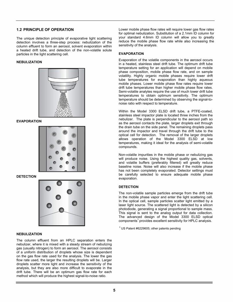
The unique detection principle of evaporative light scattering detection involves a three-step process: nebulization of the column effluent to form an aerosol, solvent evaporation within a heated drift tube, and detection of the non-volatile solute particles in the light scattering cell. NEBULIZATION EVAPORATION DETECTION
NEBULIZATION
The column effluent from an HPLC separation enters the nebulizer, where it is mixed with a steady stream of nebulizing gas (usually nitrogen) to form an aerosol. The aerosol consists of a uniform distribution of droplets whose size is dependent on the gas flow rate used for the analysis. The lower the gas flow rate used, the larger the resulting droplets will be. Larger droplets scatter more light and increase the sensitivity of the analysis, but they are also more difficult to evaporate in the drift tube. There will be an optimum gas flow rate for each method which will produce the highest signal-to-noise ratio.
Lower mobile phase flow rates will require lower gas flow rates for optimal nebulization. Substitution of a 2.1mm ID column for your standard 4.6mm ID column will allow you to greatly reduce the mobile phase flow rate while also increasing the sensitivity of the analysis.
EVAPORATION
Evaporation of the volatile components in the aerosol occurs in a heated, stainless steel drift tube. The optimum drift tube temperature setting for an application will depend on mobile phase composition, mobile phase flow rate, and on sample volatility. Highly organic mobile phases require lower drift tube temperatures for evaporation than highly aqueous mobile phases. Lower mobile phase flow rates require lower drift tube temperatures than higher mobile phase flow rates. Semi-volatile analytes require the use of much lower drift tube temperatures to obtain optimum sensitivity. The optimum temperature should be determined by observing the signal-to-noise ratio with respect to temperature. Within the Model 3300 ELSD drift tube, a PTFE-coated, stainless steel impactor plate is located three inches from the nebulizer. The plate is perpendicular to the aerosol path so as the aerosol contacts the plate, larger droplets exit through the drain tube on the side panel. The remaining droplets pass around the impactor and travel through the drift tube to the optical cell for detection. The removal of the larger droplets allows operation of the Model 3300 ELSD at low temperatures, making it ideal for the analysis of semi-volatile compounds. Non-volatile impurities in the mobile phase or nebulizing gas will produce noise. Using the highest quality gas, solvents, and volatile buffers (preferably filtered) will greatly reduce baseline noise. Noise will also increase if the mobile phase has not been completely evaporated. Detector settings must be carefully selected to ensure adequate mobile phase evaporation.
DETECTION
The non-volatile sample particles emerge from the drift tube in the mobile phase vapor and enter the light scattering cell. In the optical cell, sample particles scatter light emitted by a laser light source. The scattered light is detected by a silicon photodiode, generating a signal proportional to sample mass. This signal is sent to the analog output for data collection. The advanced design of the Model 3300 ELSD optical components1 provides excellent sensitivity for HPLC analysis. 1 US Patent #6229605; other patents pending
6
2. INSTALLATION
2.1 WHAT YOU WILL NEED
In addition to the Model 3300 ELSD detector and its accessories, the following will be needed for installation of a complete chromatographic system:
Exhaust System:
• A fume hood or other ventilation device located close to the detector to remove the detector exhaust from the laboratory.
Gas Supply:
• A supply of clean, dry nebulization gas, preferably nitrogen, regulated from 65 to 80 psig. 99.9% purity or better is recommended. The gas source can be a high-pressure gas cylinder, high-pressure liquid tank, or a nitrogen generator.
HPLC System Components:
• An HPLC pump, isocratic or gradient, capable of low-pulsation solvent delivery at a flow rate ranging from at least 0.1 to 1.5mL/min against pressures of at least 3,000 psig. Lower flow rate capabilities may be necessary for smaller bore columns.
• An autosampler or manual injection valve.
• A column capable of separating the compounds of interest. If you are uncertain which column to use, contact your Grace Davison Discovery Sciences representative or the Grace Technical Support Group for assistance (Phone: 1-800-33-SOLVE).
• A guard column or cartridge compatible with the separation column is recommended to prolong separation column lifetime.
• A column heater, if needed.
• A data system or integrator, capable of accepting analog voltage data. 0 -10mV or 0 -1000mV systems can be used.
Other:
• HPLC-grade mobile phase solvents.
• Solvent reservoirs, tubing, inlet filters, paper, etc. required for pump and data system operation. Consult the appropriate manuals for requirements.
2.2 UNPACKING
The Model 3300 ELSD detector and its accessories are shipped in the same container. Unpack components carefully, making sure all items in the list below have been included and are in good condition. Save the container and packing material for future use.
The Model 3300 ELSD shipping container should contain the following: • Model 3300 ELSD • Model 3300 ELSD Operating Manual • Model 3300 ELSD Performance Documents • Model 3300 ELSD Driver for Agilent ChemStation CD* • Power Cord • Signal Cable • PEEK Tubing: 1/16" OD x .005" ID, 10’ • SofGrip Fittings, 10/pk • Gas Tubing, 10’ • Gas Fittings: 1/8” Brass Nut and Ferrule • Drain Tubing, 5’ (Reservoir not included) • Drain Tubing Clamp • Exhaust Adaptor • Exhaust Tubing, 20’ • 14-Pin Connector • Open-End Wrench, 3/8" x 7/16" • Open-End Wrench, 1/4" x 5/16" • Hex Ball Driver, 3/32" x 5 1/4” • Hex Ball Driver, 7/64" x 4” • Drift Tube Cleaning Brush • Fuse, 5 Amp
*The 3300 ELSD Driver for Agilent ChemStation CD can be used with Agilent ChemStation to control and collect data from the 3300 ELSD. Agilent ChemStation must be purchased separately. The Model 3300 ELSD has been carefully shipped to ensure that it is received in proper condition. Any damage to the container or its contents should be reported immediately to your local distributor or to Grace Davison Discovery Sciences. Please refer to Section 7.11, Warranty, Returns, and Repairs, for more information. Refer to Section 7.3, Replacement Parts, for part numbers if replacement parts are needed.
NOTE: Make sure the exhaust system provides adequate but not excessive suction. Excessive suction can cause a noisy baseline.
NOTE: Only volatile buffers may be used in the mobile phase. Refer to Section 7.10, Volatile Mobile Phase Modifiers, for a list of
suitable buffers.
7
2.3 CONTROLS AND FEATURES
6
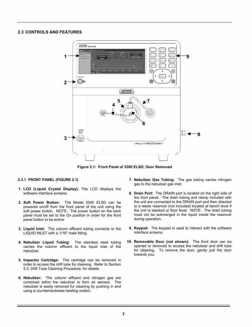
Figure 2.1: Front Panel of 3300 ELSD; Door Removed 2.3.1 FRONT PANEL (FIGURE 2.1)
1. LCD (Liquid Crystal Display): The LCD displays the software interface screens.
2. Soft Power Button: The Model 3300 ELSD can be powered on/off from the front panel of the unit using the soft power button. NOTE: The power button on the back panel must be set to the On position in order for the front panel button to be active.
3. Liquid Inlet: The column effluent tubing connects to the LIQUID INLET with a 1/16" male fitting.
4. Nebulizer Liquid Tubing: The stainless steel tubing carries the column effluent to the liquid inlet of the nebulizer.
5. Impactor Cartridge: The cartridge can be removed in order to access the drift tube for cleaning. Refer to Section 5.3, Drift Tube Cleaning Procedure, for details.
6. Nebulizer: The column effluent and nitrogen gas are combined within the nebulizer to form an aerosol. The nebulizer is easily removed for cleaning by pushing in and using a counterclockwise twisting motion.
7. Nebulizer Gas Tubing: The gas tubing carries nitrogen gas to the nebulizer gas inlet.
8. Drain Port: The DRAIN port is located on the right side of the front panel. The drain tubing and clamp included with the unit are connected to the DRAIN port and then directed to a waste reservoir (not included) located at bench level if the unit is stacked or floor level. NOTE: The drain tubing must not be submerged in the liquid inside the reservoir during operation.
9. Keypad: The keypad is used to interact with the software interface screens.
10. Removable Door (not shown): The front door can be opened or removed to access the nebulizer and drift tube for cleaning. To remove the door, gently pull the door towards you.
1
2
3
7
8
9
54
8
2.3.2 BACK PANEL (FIGURE 2.2)
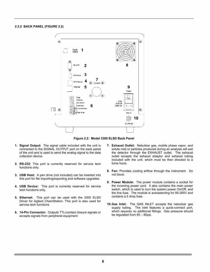
Figure 2.2: Model 3300 ELSD Back Panel 1. Signal Output: The signal cable included with the unit is
connected to the SIGNAL OUTPUT port on the back panel of the unit and is used to send the analog signal to the data collection device.
2. RS-232: This port is currently reserved for service tech functions only.
3. USB Host: A pen drive (not included) can be inserted into this port for file importing/exporting and software upgrades.
4. USB Device: This port is currently reserved for service tech functions only.
5. Ethernet: This port can be used with the 3300 ELSD Driver for Agilent ChemStation. This port is also used for service tech functions
6. 14-Pin Connector: Outputs TTL/contact closure signals or accepts signals from peripheral equipment.
7. Exhaust Outlet: Nebulizer gas, mobile phase vapor, and solute mist or particles produced during an analysis will exit the detector through the EXHAUST outlet. The exhaust outlet accepts the exhaust adaptor and exhaust tubing included with the unit, which must be then directed to a fume hood.
8. Fan: Provides cooling airflow through the instrument. Do not block.
9. Power Module: The power module contains a socket for the incoming power cord. It also contains the main power switch, which is used to turn the system power On/Off, and the line fuse. The module is autoselecting for 85-265V and contains a 5 Amp fuse.
10. Gas Inlet: The GAS INLET accepts the nebulizer gas supply tubing. The inlet features a quick-connect port, which requires no additional fittings. Gas pressure should be regulated from 65 – 80psi.
1
2
3 4
5
6
7
8
9
10
9
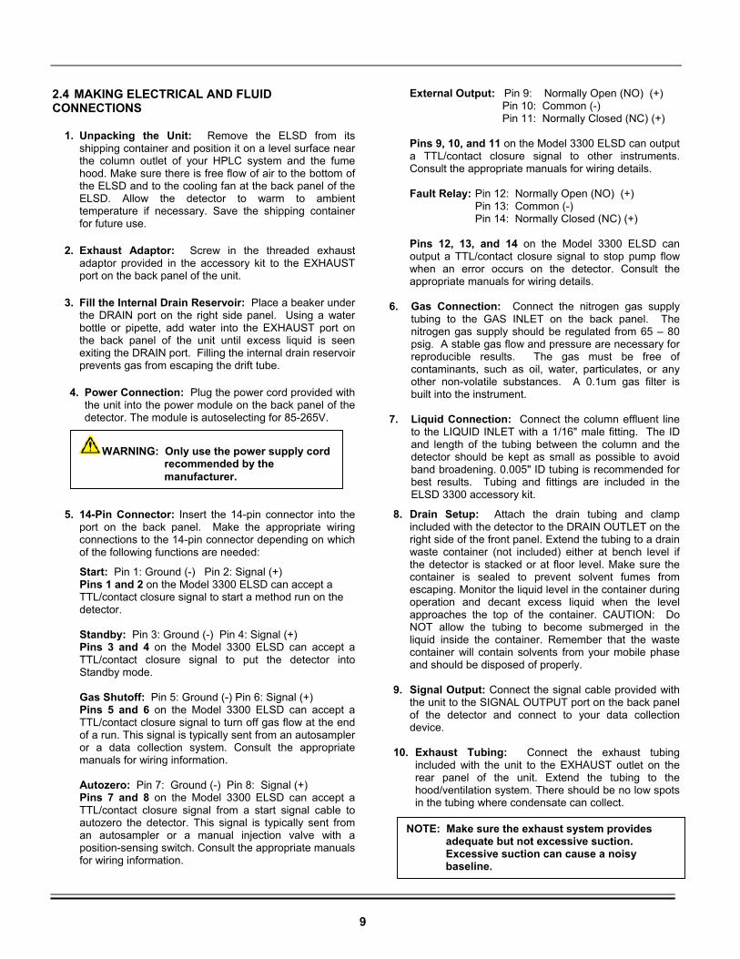
2.4 MAKING ELECTRICAL AND FLUID CONNECTIONS
1. Unpacking the Unit: Remove the ELSD from its shipping container and position it on a level surface near the column outlet of your HPLC system and the fume hood. Make sure there is free flow of air to the bottom of the ELSD and to the cooling fan at the back panel of the ELSD. Allow the detector to warm to ambient temperature if necessary. Save the shipping container for future use.
2. Exhaust Adaptor: Screw in the threaded exhaust adaptor provided in the accessory kit to the EXHAUST port on the back panel of the unit.
3. Fill the Internal Drain Reservoir: Place a beaker under the DRAIN port on the right side panel. Using a water bottle or pipette, add water into the EXHAUST port on the back panel of the unit until excess liquid is seen exiting the DRAIN port. Filling the internal drain reservoir prevents gas from escaping the drift tube.
4. Power Connection: Plug the power cord provided with the unit into the power module on the back panel of the detector. The module is autoselecting for 85-265V.
5. 14-Pin Connector: Insert the 14-pin connector into the port on the back panel. Make the appropriate wiring connections to the 14-pin connector depending on which of the following functions are needed:
Start: Pin 1: Ground (-) Pin 2: Signal (+) Pins 1 and 2 on the Model 3300 ELSD can accept a TTL/contact closure signal to start a method run on the detector.
Standby: Pin 3: Ground (-) Pin 4: Signal (+) Pins 3 and 4 on the Model 3300 ELSD can accept a TTL/contact closure signal to put the detector into Standby mode. Gas Shutoff: Pin 5: Ground (-) Pin 6: Signal (+) Pins 5 and 6 on the Model 3300 ELSD can accept a TTL/contact closure signal to turn off gas flow at the end of a run. This signal is typically sent from an autosampler or a data collection system. Consult the appropriate manuals for wiring information. Autozero: Pin 7: Ground (-) Pin 8: Signal (+) Pins 7 and 8 on the Model 3300 ELSD can accept a TTL/contact closure signal from a start signal cable to autozero the detector. This signal is typically sent from an autosampler or a manual injection valve with a position-sensing switch. Consult the appropriate manuals for wiring information.
External Output: Pin 9: Normally Open (NO) (+) Pin 10: Common (-) Pin 11: Normally Closed (NC) (+)
Pins 9, 10, and 11 on the Model 3300 ELSD can output a TTL/contact closure signal to other instruments. Consult the appropriate manuals for wiring details.
Fault Relay: Pin 12: Normally Open (NO) (+)
Pin 13: Common (-) Pin 14: Normally Closed (NC) (+)
Pins 12, 13, and 14 on the Model 3300 ELSD can output a TTL/contact closure signal to stop pump flow when an error occurs on the detector. Consult the appropriate manuals for wiring details.
6. Gas Connection: Connect the nitrogen gas supply
tubing to the GAS INLET on the back panel. The nitrogen gas supply should be regulated from 65 – 80 psig. A stable gas flow and pressure are necessary for reproducible results. The gas must be free of contaminants, such as oil, water, particulates, or any other non-volatile substances. A 0.1um gas filter is built into the instrument.
7. Liquid Connection: Connect the column effluent line
to the LIQUID INLET with a 1/16" male fitting. The ID and length of the tubing between the column and the detector should be kept as small as possible to avoid band broadening. 0.005" ID tubing is recommended for best results. Tubing and fittings are included in the ELSD 3300 accessory kit.
8. Drain Setup: Attach the drain tubing and clamp included with the detector to the DRAIN OUTLET on the right side of the front panel. Extend the tubing to a drain waste container (not included) either at bench level if the detector is stacked or at floor level. Make sure the container is sealed to prevent solvent fumes from escaping. Monitor the liquid level in the container during operation and decant excess liquid when the level approaches the top of the container. CAUTION: Do NOT allow the tubing to become submerged in the liquid inside the container. Remember that the waste container will contain solvents from your mobile phase and should be disposed of properly.
9. Signal Output: Connect the signal cable provided with
the unit to the SIGNAL OUTPUT port on the back panel of the detector and connect to your data collection device.
10. Exhaust Tubing: Connect the exhaust tubing
included with the unit to the EXHAUST outlet on the rear panel of the unit. Extend the tubing to the hood/ventilation system. There should be no low spots in the tubing where condensate can collect.
WARNING: Only use the power supply cord recommended by the manufacturer.
NOTE: Make sure the exhaust system provides adequate but not excessive suction. Excessive suction can cause a noisy baseline.
10
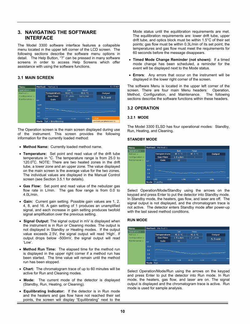
3. NAVIGATING THE SOFTWARE INTERFACE
The Model 3300 software interface features a collapsible menu located in the upper left corner of the LCD screen. The following sections describe the software menu options in detail. The Help Button, “?” can be pressed in many software screens in order to access Help Screens which offer assistance with using the software functions.
3.1 MAIN SCREEN
The Operation screen is the main screen displayed during use of the instrument. This screen provides the following information for the currently loaded method: • Method Name: Currently loaded method name.
• Temperature: Set point and read value of the drift tube temperature in °C. The temperature range is from 25.0 to 120.0oC. NOTE: There are two heated zones in the drift tube, a lower zone and an upper zone. The value displayed on the main screen is the average value for the two zones. The individual values are displayed in the Manual Control screen (see Section 3.5.1 for details).
• Gas Flow: Set point and read value of the nebulizer gas flow rate in L/min. The gas flow range is from 0.0 to 4.0L/min.
• Gain: Current gain setting. Possible gain values are 1, 2, 4, 8, and 16. A gain setting of 1 produces an unamplified signal, and each increase in gain setting produces twofold signal amplification over the previous setting.
• Signal Output: The signal output in mV is displayed when the instrument is in Run or Cleaning modes. The output is not displayed in Standby or Heating modes. If the output value exceeds 2.5V, the signal output will read ‘High’. If output drops below -500mV, the signal output will read ‘Low’.
• Method Run Time: The elapsed time for the method run is displayed in the upper right corner if a method run has been started. The time value will remain until the method run has been stopped.
• Chart: The chromatogram trace of up to 60 minutes will be active for Run and Cleaning modes.
• Mode: The current mode of the detector is displayed (Standby, Run, Heating, or Cleaning).
• Equilibrating Indicator: If the detector is in Run mode and the heaters and gas flow have not reached their set points, the screen will display “Equilibrating” next to the
Mode status until the equilibration requirements are met. The equilibration requirements are: lower drift tube, upper drift tube, and optics block must be within 1.5°C of their set points; gas flow must be within 0.3L/min of its set point; the temperatures and gas flow must meet the requirements for 60 seconds before the message disappears.
• Timed Mode Change Reminder (not shown): If a timed mode change has been scheduled, a reminder for the event will be displayed next to the Mode status.
• Errors: Any errors that occur on the instrument will be displayed in the lower right corner of the screen.
The software Menu is located in the upper left corner of the screen. There are four main Menu headers: Operation, Method, Configuration, and Maintenance. The following sections describe the software functions within these headers.
3.2 OPERATION
3.2.1 MODE
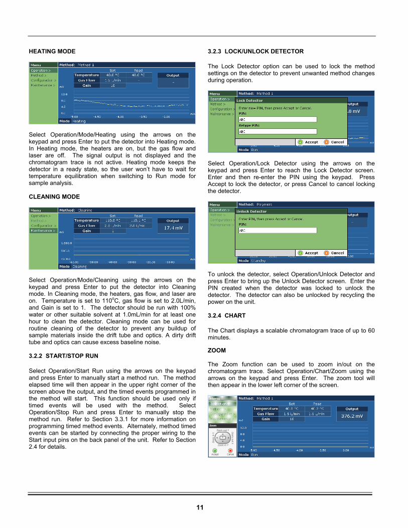
The Model 3300 ELSD has four operational modes: Standby, Run, Heating, and Cleaning. STANDBY MODE
Select Operation/Mode/Standby using the arrows on the keypad and press Enter to put the detector into Standby mode. In Standby mode, the heaters, gas flow, and laser are off. The signal output is not displayed, and the chromatogram trace is not active. The detector enters Standby mode after power-up with the last saved method conditions. RUN MODE
Select Operation/Mode/Run using the arrows on the keypad and press Enter to put the detector into Run mode. In Run mode, the heaters, gas flow, and laser are on. The signal output is displayed and the chromatogram trace is active. Run mode is used for sample analysis.
11
HEATING MODE
Select Operation/Mode/Heating using the arrows on the keypad and press Enter to put the detector into Heating mode. In Heating mode, the heaters are on, but the gas flow and laser are off. The signal output is not displayed and the chromatogram trace is not active. Heating mode keeps the detector in a ready state, so the user won’t have to wait for temperature equilibration when switching to Run mode for sample analysis. CLEANING MODE
Select Operation/Mode/Cleaning using the arrows on the keypad and press Enter to put the detector into Cleaning mode. In Cleaning mode, the heaters, gas flow, and laser are on. Temperature is set to 110oC, gas flow is set to 2.0L/min, and Gain is set to 1. The detector should be run with 100% water or other suitable solvent at 1.0mL/min for at least one hour to clean the detector. Cleaning mode can be used for routine cleaning of the detector to prevent any buildup of sample materials inside the drift tube and optics. A dirty drift tube and optics can cause excess baseline noise. 3.2.2 START/STOP RUN
Select Operation/Start Run using the arrows on the keypad and press Enter to manually start a method run. The method elapsed time will then appear in the upper right corner of the screen above the output, and the timed events programmed in the method will start. This function should be used only if timed events will be used with the method. Select Operation/Stop Run and press Enter to manually stop the method run. Refer to Section 3.3.1 for more information on programming timed method events. Alternately, method timed events can be started by connecting the proper wiring to the Start input pins on the back panel of the unit. Refer to Section 2.4 for details.
3.2.3 LOCK/UNLOCK DETECTOR
The Lock Detector option can be used to lock the method settings on the detector to prevent unwanted method changes during operation.
Select Operation/Lock Detector using the arrows on the keypad and press Enter to reach the Lock Detector screen. Enter and then re-enter the PIN using the keypad. Press Accept to lock the detector, or press Cancel to cancel locking the detector.
To unlock the detector, select Operation/Unlock Detector and press Enter to bring up the Unlock Detector screen. Enter the PIN created when the detector was locked to unlock the detector. The detector can also be unlocked by recycling the power on the unit. 3.2.4 CHART
The Chart displays a scalable chromatogram trace of up to 60 minutes. ZOOM The Zoom function can be used to zoom in/out on the chromatogram trace. Select Operation/Chart/Zoom using the arrows on the keypad and press Enter. The zoom tool will then appear in the lower left corner of the screen.
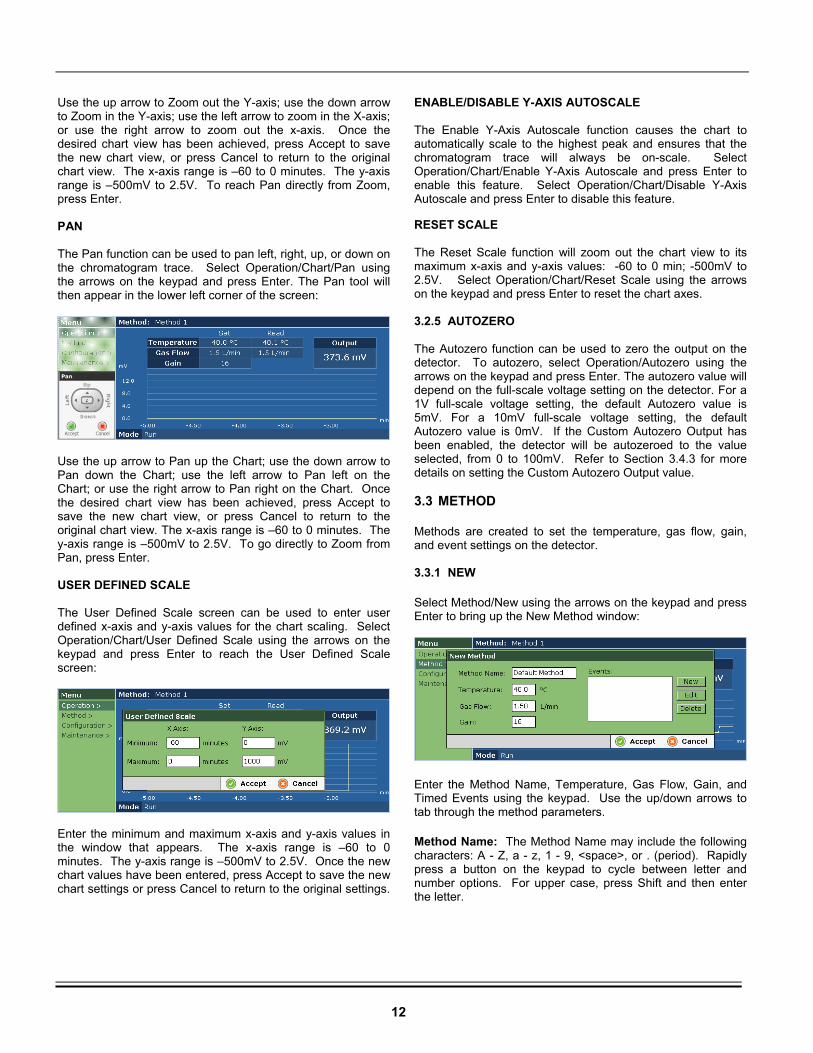
12
Use the up arrow to Zoom out the Y-axis; use the down arrow to Zoom in the Y-axis; use the left arrow to zoom in the X-axis; or use the right arrow to zoom out the x-axis. Once the desired chart view has been achieved, press Accept to save the new chart view, or press Cancel to return to the original chart view. The x-axis range is –60 to 0 minutes. The y-axis range is –500mV to 2.5V. To reach Pan directly from Zoom, press Enter. PAN The Pan function can be used to pan left, right, up, or down on the chromatogram trace. Select Operation/Chart/Pan using the arrows on the keypad and press Enter. The Pan tool will then appear in the lower left corner of the screen:
Use the up arrow to Pan up the Chart; use the down arrow to Pan down the Chart; use the left arrow to Pan left on the Chart; or use the right arrow to Pan right on the Chart. Once the desired chart view has been achieved, press Accept to save the new chart view, or press Cancel to return to the original chart view. The x-axis range is –60 to 0 minutes. The y-axis range is –500mV to 2.5V. To go directly to Zoom from Pan, press Enter. USER DEFINED SCALE The User Defined Scale screen can be used to enter user defined x-axis and y-axis values for the chart scaling. Select Operation/Chart/User Defined Scale using the arrows on the keypad and press Enter to reach the User Defined Scale screen:
Enter the minimum and maximum x-axis and y-axis values in the window that appears. The x-axis range is –60 to 0 minutes. The y-axis range is –500mV to 2.5V. Once the new chart values have been entered, press Accept to save the new chart settings or press Cancel to return to the original settings.
ENABLE/DISABLE Y-AXIS AUTOSCALE The Enable Y-Axis Autoscale function causes the chart to automatically scale to the highest peak and ensures that the chromatogram trace will always be on-scale. Select Operation/Chart/Enable Y-Axis Autoscale and press Enter to enable this feature. Select Operation/Chart/Disable Y-Axis Autoscale and press Enter to disable this feature. RESET SCALE The Reset Scale function will zoom out the chart view to its maximum x-axis and y-axis values: -60 to 0 min; -500mV to 2.5V. Select Operation/Chart/Reset Scale using the arrows on the keypad and press Enter to reset the chart axes. 3.2.5 AUTOZERO The Autozero function can be used to zero the output on the detector. To autozero, select Operation/Autozero using the arrows on the keypad and press Enter. The autozero value will depend on the full-scale voltage setting on the detector. For a 1V full-scale voltage setting, the default Autozero value is 5mV. For a 10mV full-scale voltage setting, the default Autozero value is 0mV. If the Custom Autozero Output has been enabled, the detector will be autozeroed to the value selected, from 0 to 100mV. Refer to Section 3.4.3 for more details on setting the Custom Autozero Output value. 3.3 METHOD
Methods are created to set the temperature, gas flow, gain, and event settings on the detector. 3.3.1 NEW
Select Method/New using the arrows on the keypad and press Enter to bring up the New Method window:
Enter the Method Name, Temperature, Gas Flow, Gain, and Timed Events using the keypad. Use the up/down arrows to tab through the method parameters.
Method Name: The Method Name may include the following characters: A - Z, a - z, 1 - 9, <space>, or . (period). Rapidly press a button on the keypad to cycle between letter and number options. For upper case, press Shift and then enter the letter.
13
Temperature: Enter a temperature value between 25 -120oC using the keypad.
Gas Flow: Enter a value between 0.0 – 4.0L/min using the keypad.
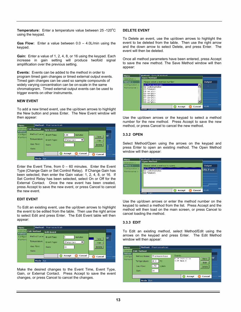
Gain: Enter a value of 1, 2, 4, 8, or 16 using the keypad. Each increase in gain setting will produce twofold signal amplification over the previous setting. Events: Events can be added to the method in order to program timed gain changes or timed external output events. Timed gain changes can be used so sample compounds of widely varying concentration can be on-scale in the same chromatogram. Timed external output events can be used to trigger events on other instruments. NEW EVENT To add a new timed event, use the up/down arrows to highlight the New button and press Enter. The New Event window will then appear:
Enter the Event Time, from 0 – 60 minutes. Enter the Event Type (Change Gain or Set Control Relay). If Change Gain has been selected, then enter the Gain value: 1, 2, 4, 8, or 16. If Set Control Relay has been selected, select On or Off for the External Contact. Once the new event has been created, press Accept to save the new event, or press Cancel to cancel the new event. EDIT EVENT To Edit an existing event, use the up/down arrows to highlight the event to be edited from the table. Then use the right arrow to select Edit and press Enter. The Edit Event table will then appear:
Make the desired changes to the Event Time, Event Type, Gain, or External Contact. Press Accept to save the event changes, or press Cancel to cancel the changes.
DELETE EVENT To Delete an event, use the up/down arrows to highlight the event to be deleted from the table. Then use the right arrow and the down arrow to select Delete, and press Enter. The event will then be deleted. Once all method parameters have been entered, press Accept to save the new method. The Save Method window will then appear:
Use the up/down arrows or the keypad to select a method number for the new method. Press Accept to save the new method, or press Cancel to cancel the new method.
3.3.2 OPEN
Select Method/Open using the arrows on the keypad and press Enter to open an existing method. The Open Method window will then appear:
Use the up/down arrows or enter the method number on the keypad to select a method from the list. Press Accept and the method will then load on the main screen, or press Cancel to cancel loading the method.
3.3.3 EDIT
To Edit an existing method, select Method/Edit using the arrows on the keypad and press Enter. The Edit Method window will then appear:
14
Use the up/down arrows to tab through the method parameters and enter a new Method Name, Temperature, Gas Flow, Gain, and/or Events using the keypad. Press Accept to save the new method settings, or press Cancel to return to the original method settings.
3.3.4 DELETE
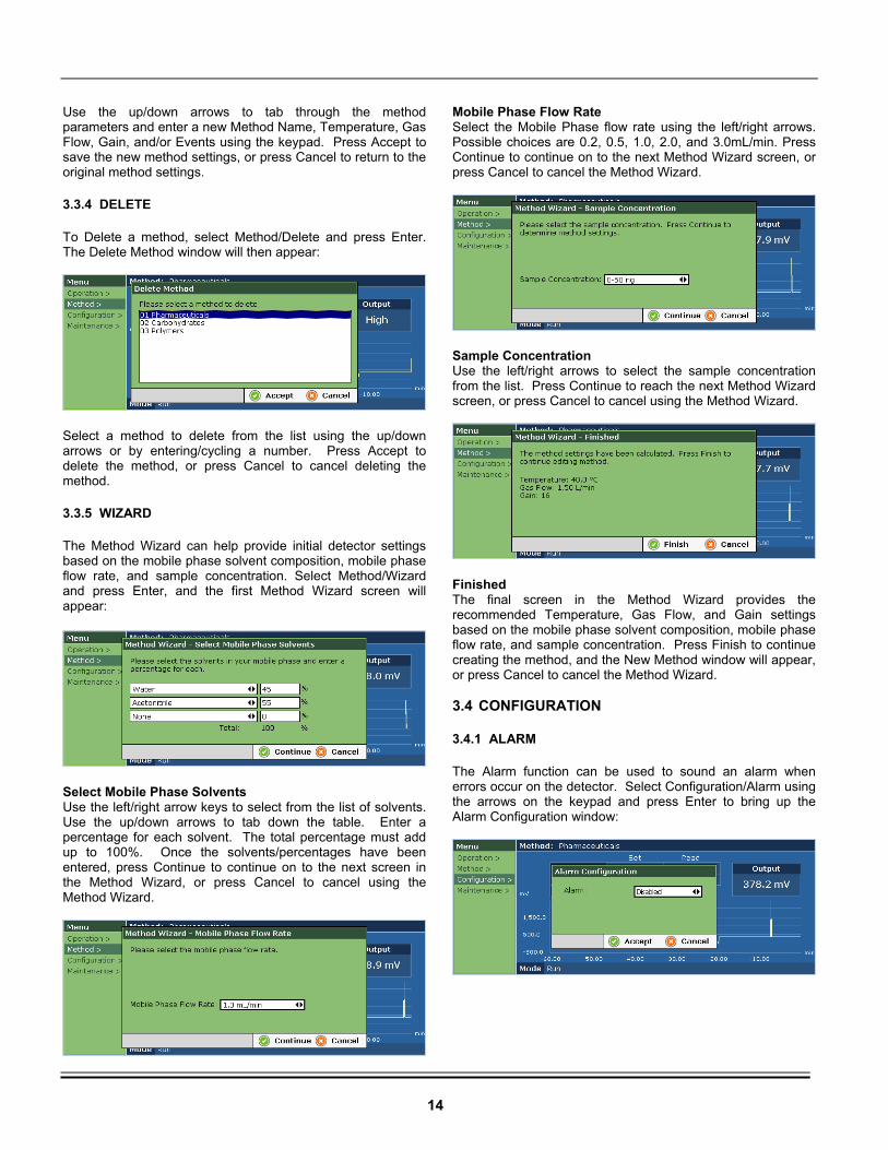
To Delete a method, select Method/Delete and press Enter. The Delete Method window will then appear:
Select a method to delete from the list using the up/down arrows or by entering/cycling a number. Press Accept to delete the method, or press Cancel to cancel deleting the method.
3.3.5 WIZARD
The Method Wizard can help provide initial detector settings based on the mobile phase solvent composition, mobile phase flow rate, and sample concentration. Select Method/Wizard and press Enter, and the first Method Wizard screen will appear:
Select Mobile Phase Solvents Use the left/right arrow keys to select from the list of solvents. Use the up/down arrows to tab down the table. Enter a percentage for each solvent. The total percentage must add up to 100%. Once the solvents/percentages have been entered, press Continue to continue on to the next screen in the Method Wizard, or press Cancel to cancel using the Method Wizard.
Mobile Phase Flow Rate Select the Mobile Phase flow rate using the left/right arrows. Possible choices are 0.2, 0.5, 1.0, 2.0, and 3.0mL/min. Press Continue to continue on to the next Method Wizard screen, or press Cancel to cancel the Method Wizard.
Sample Concentration Use the left/right arrows to select the sample concentration from the list. Press Continue to reach the next Method Wizard screen, or press Cancel to cancel using the Method Wizard.
Finished The final screen in the Method Wizard provides the recommended Temperature, Gas Flow, and Gain settings based on the mobile phase solvent composition, mobile phase flow rate, and sample concentration. Press Finish to continue creating the method, and the New Method window will appear, or press Cancel to cancel the Method Wizard. 3.4 CONFIGURATION
3.4.1 ALARM
The Alarm function can be used to sound an alarm when errors occur on the detector. Select Configuration/Alarm using the arrows on the keypad and press Enter to bring up the Alarm Configuration window:
15
Use the left/right arrows to select Enabled or Disabled. If Enabled, the alarm will sound when errors occur on the unit and will continue to sound until the errors are remedied. If Disabled, the alarm will not sound when errors occur on the unit. Press Accept to save the alarm configuration, or press Cancel to return to the original alarm configuration. 3.4.2 SERIAL NUMBER
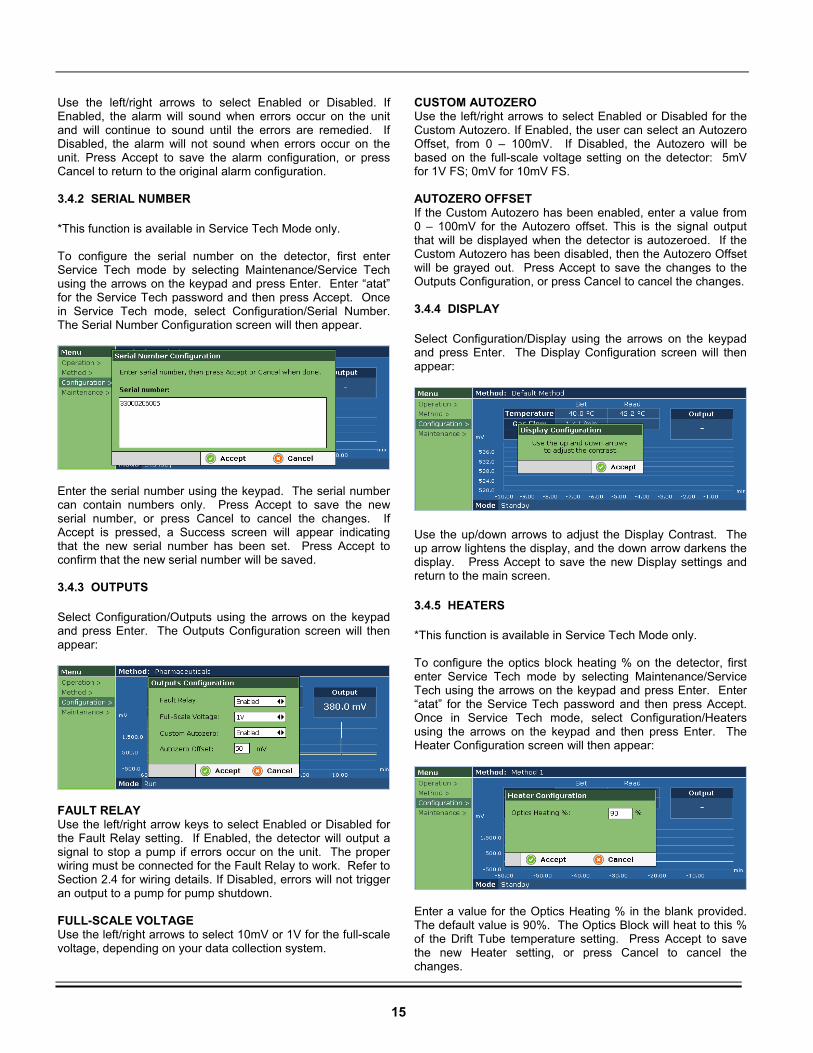
*This function is available in Service Tech Mode only. To configure the serial number on the detector, first enter Service Tech mode by selecting Maintenance/Service Tech using the arrows on the keypad and press Enter. Enter “atat” for the Service Tech password and then press Accept. Once in Service Tech mode, select Configuration/Serial Number. The Serial Number Configuration screen will then appear.
Enter the serial number using the keypad. The serial number can contain numbers only. Press Accept to save the new serial number, or press Cancel to cancel the changes. If Accept is pressed, a Success screen will appear indicating that the new serial number has been set. Press Accept to confirm that the new serial number will be saved. 3.4.3 OUTPUTS
Select Configuration/Outputs using the arrows on the keypad and press Enter. The Outputs Configuration screen will then appear:
FAULT RELAY Use the left/right arrow keys to select Enabled or Disabled for the Fault Relay setting. If Enabled, the detector will output a signal to stop a pump if errors occur on the unit. The proper wiring must be connected for the Fault Relay to work. Refer to Section 2.4 for wiring details. If Disabled, errors will not trigger an output to a pump for pump shutdown. FULL-SCALE VOLTAGE Use the left/right arrows to select 10mV or 1V for the full-scale voltage, depending on your data collection system.
CUSTOM AUTOZERO Use the left/right arrows to select Enabled or Disabled for the Custom Autozero. If Enabled, the user can select an Autozero Offset, from 0 – 100mV. If Disabled, the Autozero will be based on the full-scale voltage setting on the detector: 5mV for 1V FS; 0mV for 10mV FS. AUTOZERO OFFSET If the Custom Autozero has been enabled, enter a value from 0 – 100mV for the Autozero offset. This is the signal output that will be displayed when the detector is autozeroed. If the Custom Autozero has been disabled, then the Autozero Offset will be grayed out. Press Accept to save the changes to the Outputs Configuration, or press Cancel to cancel the changes. 3.4.4 DISPLAY
Select Configuration/Display using the arrows on the keypad and press Enter. The Display Configuration screen will then appear:
Use the up/down arrows to adjust the Display Contrast. The up arrow lightens the display, and the down arrow darkens the display. Press Accept to save the new Display settings and return to the main screen.
3.4.5 HEATERS
*This function is available in Service Tech Mode only. To configure the optics block heating % on the detector, first enter Service Tech mode by selecting Maintenance/Service Tech using the arrows on the keypad and press Enter. Enter “atat” for the Service Tech password and then press Accept. Once in Service Tech mode, select Configuration/Heaters using the arrows on the keypad and then press Enter. The Heater Configuration screen will then appear:
Enter a value for the Optics Heating % in the blank provided. The default value is 90%. The Optics Block will heat to this % of the Drift Tube temperature setting. Press Accept to save the new Heater setting, or press Cancel to cancel the changes.
16
3.4.6 DATE AND TIME
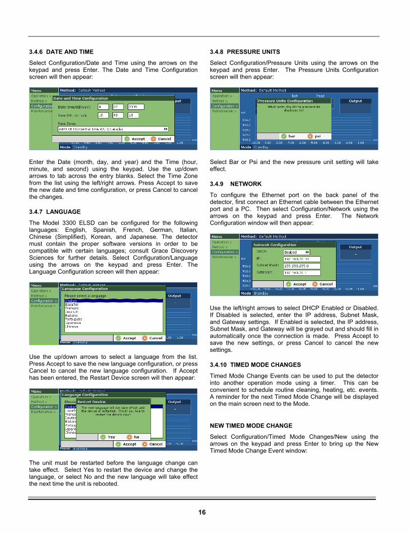
Select Configuration/Date and Time using the arrows on the keypad and press Enter. The Date and Time Configuration screen will then appear:
Enter the Date (month, day, and year) and the Time (hour, minute, and second) using the keypad. Use the up/down arrows to tab across the entry blanks. Select the Time Zone from the list using the left/right arrows. Press Accept to save the new date and time configuration, or press Cancel to cancel the changes.
3.4.7 LANGUAGE
The Model 3300 ELSD can be configured for the following languages: English, Spanish, French, German, Italian, Chinese (Simplified), Korean, and Japanese. The detector must contain the proper software versions in order to be compatible with certain languages; consult Grace Discovery Sciences for further details. Select Configuration/Language using the arrows on the keypad and press Enter. The Language Configuration screen will then appear:
Use the up/down arrows to select a language from the list. Press Accept to save the new language configuration, or press Cancel to cancel the new language configuration. If Accept has been entered, the Restart Device screen will then appear:
The unit must be restarted before the language change can take effect. Select Yes to restart the device and change the language, or select No and the new language will take effect the next time the unit is rebooted.
3.4.8 PRESSURE UNITS
Select Configuration/Pressure Units using the arrows on the keypad and press Enter. The Pressure Units Configuration screen will then appear:
Select Bar or Psi and the new pressure unit setting will take effect.
3.4.9 NETWORK
To configure the Ethernet port on the back panel of the detector, first connect an Ethernet cable between the Ethernet port and a PC. Then select Configuration/Network using the arrows on the keypad and press Enter. The Network Configuration window will then appear:
Use the left/right arrows to select DHCP Enabled or Disabled. If Disabled is selected, enter the IP address, Subnet Mask, and Gateway settings. If Enabled is selected, the IP address, Subnet Mask, and Gateway will be grayed out and should fill in automatically once the connection is made. Press Accept to save the new settings, or press Cancel to cancel the new settings.
3.4.10 TIMED MODE CHANGES
Timed Mode Change Events can be used to put the detector into another operation mode using a timer. This can be convenient to schedule routine cleaning, heating, etc. events. A reminder for the next Timed Mode Change will be displayed on the main screen next to the Mode.
NEW TIMED MODE CHANGE
Select Configuration/Timed Mode Changes/New using the arrows on the keypad and press Enter to bring up the New Timed Mode Change Event window:
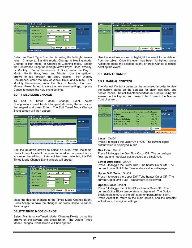
17
Select an Event Type from the list using the left/right arrows keys: Change to Standby mode, Change to Heating mode, Change to Run mode, or Change to Cleaning mode. Select the Recurrence using the left/right arrow keys: Once, Weekly, or Monthly. For a Recurrence of Once, enter the Day of Month, Month, Hour, Year, and Minute. Use the up/down arrows to tab through the entry blanks. For Weekly Recurrence, enter the Day of Week, Hour, and Minute. For Monthly Recurrence, enter the Day of Month, Hour, and Minute. Press Accept to save the new event settings, or press Cancel to cancel the new event settings.
EDIT TIMED MODE CHANGE To Edit a Timed Mode Change Event, select Configuration/Timed Mode Changes/Edit using the arrows on the keypad and press Enter. The Edit Timed Mode Change Event screen will then appear:
Use the up/down arrows to select an event from the table. Press Accept to select the event to be edited, or press Cancel to cancel the editing. If Accept has been selected, the Edit Timed Mode Change Event window will appear:
Make the desired changes to the Timed Mode Change Event. Press Accept to save the changes, or press Cancel to cancel the changes.
DELETE TIMED MODE CHANGE
Select Maintenance/Timed Mode Changes/Delete using the arrows on the keypad and press Enter. The Delete Timed Mode Changes Event screen will then appear:
Use the up/down arrows to highlight the event to be deleted from the table. Once the event has been highlighted, press Accept to delete the selected event, or press Cancel to cancel deleting the event.
3.5 MAINTENANCE
3.5.1 MANUAL CONTROL
The Manual Control screen can be accessed in order to view the current status on the detector for laser, gas flow, and heated zones. Select Maintenance/Manual Control using the arrows on the keypad and press Enter to reach the Manual Control screen:
Laser: On/Off Press 1 to toggle the Laser On or Off. The current signal output value is displayed in mV.
Gas Flow: On/Off Press 2 to toggle the Gas Flow On or Off. The current gas flow rate and nebulizer gas pressure are displayed.
Lower Drift Tube: On/Off Press 3 to toggle the Lower Drift Tube heater On or Off. The current Lower Drift Tube Temperature value is displayed.
Upper Drift Tube: On/Off Press 4 to toggle the Upper Drift Tube heater On or Off. The current Upper Drift Tube Temperature is displayed.
Optics Block: On/Off Press 5 to toggle the Optics Block heater On or Off. The current Optics Block temperature is displayed. The Optics Block heats to 90% of the drift tube temperature set point. Press Accept to return to the main screen, and the detector will return to its original settings.
18
3.5.2 LOGS
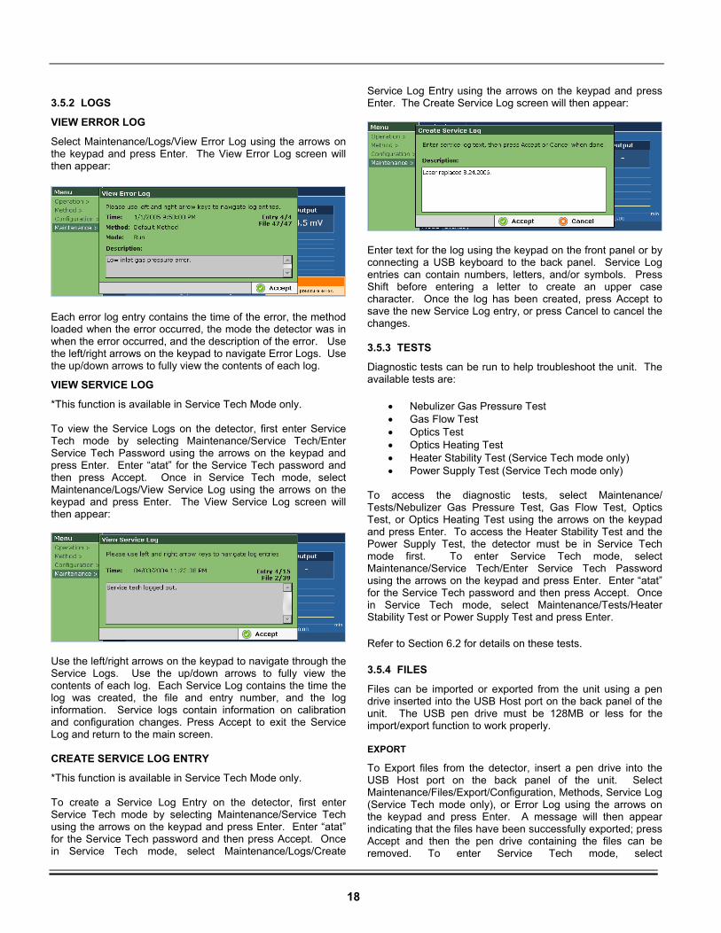
VIEW ERROR LOG
Select Maintenance/Logs/View Error Log using the arrows on the keypad and press Enter. The View Error Log screen will then appear:
Each error log entry contains the time of the error, the method loaded when the error occurred, the mode the detector was in when the error occurred, and the description of the error. Use the left/right arrows on the keypad to navigate Error Logs. Use the up/down arrows to fully view the contents of each log.
VIEW SERVICE LOG
*This function is available in Service Tech Mode only. To view the Service Logs on the detector, first enter Service Tech mode by selecting Maintenance/Service Tech/Enter Service Tech Password using the arrows on the keypad and press Enter. Enter “atat” for the Service Tech password and then press Accept. Once in Service Tech mode, select Maintenance/Logs/View Service Log using the arrows on the keypad and press Enter. The View Service Log screen will then appear:
Use the left/right arrows on the keypad to navigate through the Service Logs. Use the up/down arrows to fully view the contents of each log. Each Service Log contains the time the log was created, the file and entry number, and the log information. Service logs contain information on calibration and configuration changes. Press Accept to exit the Service Log and return to the main screen. CREATE SERVICE LOG ENTRY
*This function is available in Service Tech Mode only. To create a Service Log Entry on the detector, first enter Service Tech mode by selecting Maintenance/Service Tech using the arrows on the keypad and press Enter. Enter “atat” for the Service Tech password and then press Accept. Once in Service Tech mode, select Maintenance/Logs/Create
Service Log Entry using the arrows on the keypad and press Enter. The Create Service Log screen will then appear:
Enter text for the log using the keypad on the front panel or by connecting a USB keyboard to the back panel. Service Log entries can contain numbers, letters, and/or symbols. Press Shift before entering a letter to create an upper case character. Once the log has been created, press Accept to save the new Service Log entry, or press Cancel to cancel the changes. 3.5.3 TESTS
Diagnostic tests can be run to help troubleshoot the unit. The available tests are:
• Nebulizer Gas Pressure Test • Gas Flow Test • Optics Test • Optics Heating Test • Heater Stability Test (Service Tech mode only) • Power Supply Test (Service Tech mode only)
To access the diagnostic tests, select Maintenance/ Tests/Nebulizer Gas Pressure Test, Gas Flow Test, Optics Test, or Optics Heating Test using the arrows on the keypad and press Enter. To access the Heater Stability Test and the Power Supply Test, the detector must be in Service Tech mode first. To enter Service Tech mode, select Maintenance/Service Tech/Enter Service Tech Password using the arrows on the keypad and press Enter. Enter “atat” for the Service Tech password and then press Accept. Once in Service Tech mode, select Maintenance/Tests/Heater Stability Test or Power Supply Test and press Enter.
Refer to Section 6.2 for details on these tests.
3.5.4 FILES
Files can be imported or exported from the unit using a pen drive inserted into the USB Host port on the back panel of the unit. The USB pen drive must be 128MB or less for the import/export function to work properly. EXPORT
To Export files from the detector, insert a pen drive into the USB Host port on the back panel of the unit. Select Maintenance/Files/Export/Configuration, Methods, Service Log (Service Tech mode only), or Error Log using the arrows on the keypad and press Enter. A message will then appear indicating that the files have been successfully exported; press Accept and then the pen drive containing the files can be removed. To enter Service Tech mode, select
19
Maintenance/Service Tech using the arrows on the keypad and press Enter. Enter “atat” for the Service Tech password and then press Accept.
IMPORT
To Import files to the detector, insert a pen drive containing the files into the USB Host port on the back panel of the unit. Select Maintenance/Files/Import/Configuration or Methods and press Enter. A message will then appear indicating that the files have been successfully imported; press Accept and the pen drive can then be removed. The files to be imported must be located inside a folder named “Alltech” on the pen drive in order for the import to be successful.
3.5.5 SERVICE TECH
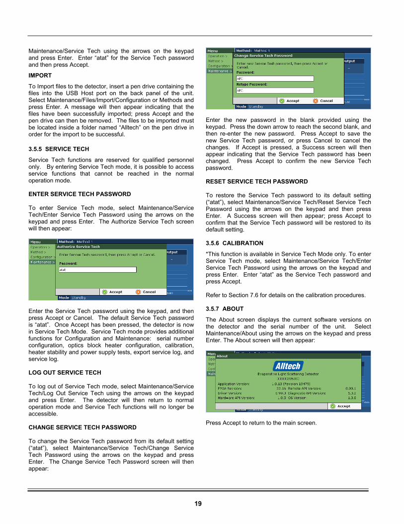
Service Tech functions are reserved for qualified personnel only. By entering Service Tech mode, it is possible to access service functions that cannot be reached in the normal operation mode. ENTER SERVICE TECH PASSWORD To enter Service Tech mode, select Maintenance/Service Tech/Enter Service Tech Password using the arrows on the keypad and press Enter. The Authorize Service Tech screen will then appear:
Enter the Service Tech password using the keypad, and then press Accept or Cancel. The default Service Tech password is “atat”. Once Accept has been pressed, the detector is now in Service Tech Mode. Service Tech mode provides additional functions for Configuration and Maintenance: serial number configuration, optics block heater configuration, calibration, heater stability and power supply tests, export service log, and service log. LOG OUT SERVICE TECH To log out of Service Tech mode, select Maintenance/Service Tech/Log Out Service Tech using the arrows on the keypad and press Enter. The detector will then return to normal operation mode and Service Tech functions will no longer be accessible. CHANGE SERVICE TECH PASSWORD To change the Service Tech password from its default setting (“atat”), select Maintenance/Service Tech/Change Service Tech Password using the arrows on the keypad and press Enter. The Change Service Tech Password screen will then appear:
Enter the new password in the blank provided using the keypad. Press the down arrow to reach the second blank, and then re-enter the new password. Press Accept to save the new Service Tech password, or press Cancel to cancel the changes. If Accept is pressed, a Success screen will then appear indicating that the Service Tech password has been changed. Press Accept to confirm the new Service Tech password. RESET SERVICE TECH PASSWORD To restore the Service Tech password to its default setting (“atat”), select Maintenance/Service Tech/Reset Service Tech Password using the arrows on the keypad and then press Enter. A Success screen will then appear; press Accept to confirm that the Service Tech password will be restored to its default setting. 3.5.6 CALIBRATION
*This function is available in Service Tech Mode only. To enter Service Tech mode, select Maintenance/Service Tech/Enter Service Tech Password using the arrows on the keypad and press Enter. Enter “atat” as the Service Tech password and press Accept. Refer to Section 7.6 for details on the calibration procedures. 3.5.7 ABOUT
The About screen displays the current software versions on the detector and the serial number of the unit. Select Maintenance/About using the arrows on the keypad and press Enter. The About screen will then appear:
Press Accept to return to the main screen.
20
4. ROUTINE OPERATION
4.1 SAFETY
Please use the following guidelines to insure safe operation of the Model 3300 ELSD:
1. Warning: Be sure to provide proper ventilation for all solvent vapors.
2. Warning: Use a fume hood or other ventilation device to prevent the inhalation of any solvent fumes expelled through the exhaust tube.
3. Warning: Avoid open flames and sparks when using flammable solvents.
4. Warning: Always power off before removing the cover.
5. Warning: Laser Radiation – Avoid exposure to beam – Class IIIB laser. 4.2 OPERATING NOTES
1. The internal drain reservoir must be filled with liquid (water) prior to using the detector. The reservoir can be filled through the EXHAUST port on the back panel. Once water is visibly draining from the DRAIN port on the right side panel, the internal drain reservoir has been filled.
2. Monitor the liquid level in the drain waste container and remove excess liquid when necessary. Never let the end of the drain tubing become submerged in the liquid inside the container.
3. Mobile phase should not be flowing when the drift tube is not at proper vaporization temperature or when the nebulizer gas is turned off.
4. Only volatile buffers are allowed in the mobile phase. Non-volatile buffer particles will be viewed as sample by the detector, causing unwanted baseline noise. Refer to Section 7.10, Volatile Mobile Phase Modifiers, for a list of suitable buffers.
4.3 SELECTING INITIAL OPERATING CONDITIONS
Use the recommendations provided by the Method Wizard for initial method settings. The Method Wizard can be reached by selecting Method/Wizard in the software interface. Refer to Section 3.3.5 for details.
Semi-Volatile Compounds
The recommendations provided by the Method Wizard are based on non-volatile sample compounds. If the sample compound is semi-volatile, it may require a lower drift tube temperature than the Method Wizard recommends. Some experimentation may be necessary.
Gradient Separations
Choose operating conditions based on the least volatile portion of the mobile phase when performing gradient separations.
Unlisted Solvents
For any solvents not listed in the Method Wizard, please refer to the solvent’s boiling point and vapor pressure in a reference book such as the Merck Index or Handbook of Chemistry and Physics. Use the temperature and gas flow rate for the solvent that most closely matches the boiling point and vapor pressure of the solvent of interest. 4.4 STARTUP SEQUENCE
1. Set up the unit as described in Section 2.4, Making Electrical and Fluid Connections.
2. Turn on the nebulizer gas supply. Set the regulator between 65 and 80 psig.
3. Power up the Model 3300 ELSD.
4. When the Operation screen appears, set up the desired method and configuration as indicated in Sections 3.3 and 3.4.
5. Put the detector into Run mode (Operation/Mode/Run).
6. Allow the detector to equilibrate. The Equilibrating indicator will appear next to the Mode in the lower left corner until the Lower Drift Tube heater, Upper Drift Tube heater, Optics Block heater, and Gas Flow reach their set points.
7. Once the detector has equilibrated, record a gas-only baseline for 10-15 minutes. Observe the signal output displayed on the front panel and on the chromatogram. You should get a stable, low-noise baseline. The noise should be in the millivolt range, within 2mV.
8. If the baseline is unstable and/or drifting, the unit may need longer equilibration time.
9. If the noise is higher than expected, you may want to perform the optics test to determine if there is a possible laser or electronics problem. Refer to Section 6.2.3 for details on the optics test.
CLASS 1 LASER PRODUCT Contains a class 3B 30mW-650nm laser. Designed to comply with 21CFR 1040.10, 1040.11, and IEC60825 with amendments as of date of manufacture. No user serviceable components inside. Refer servicing to qualified personnel.
21
10. Flush the column with mobile phase before connecting it to the detector. The length of purging will depend on how long the column was in storage and what type of sample and mobile phase were used. It is very important that the column is free from silica “fines” or other contaminants before connecting to the ELSD. The Model 3300 ELSD will detect the contaminants with great sensitivity.
11. After flushing the column, connect it to the LIQUID INLET on the left side of the front panel on the detector. The tubing between the column and the nebulizer should be a short as possible. 0.005” ID tubing is recommended.
12. Turn the pump on to the desired flow rate. Do not exceed the recommended maximum solvent rates.
13. Check connections for leaks and tighten the fittings, if necessary.
14. Observe the signal output on the display and the recorded baseline. After an initial large rise when the pump is turned on, the signal level should drop close to the “gas only” level after several minutes. If it remains high after sufficient equilibration time, the mobile phase may be contaminated (column fines, buffers, etc.), or the temperature or gas flow settings may be too low for optimal evaporation of the mobile phase. Take corrective measures and allow the system to re-equilibrate for a few minutes.
15. The detector is ready for sample analysis. The first time the Model 3300 ELSD is used, you may want to reproduce the Model 3300 ELSD QC procedure. Refer to Section 7.9 for details.
4.5 SHUTDOWN SEQUENCE
1. Turn off the mobile phase flow.
2. Allow gas only to flow for approximately five minutes to clear any remaining droplets.
3. Put the detector in Standby mode (Operation/Mode/Standby).
4. Turn off the gas supply at the source, if required.
5. Power off the ELSD using either the soft power button on the front panel, or the main power switch on the rear panel.
4.6 OPTIMIZATION PROCEDURE
1. Set the drift tube temperature, gas flow, and gain to the initial settings recommended in Section 4.3
2. Start mobile phase flow and allow the system to equilibrate.
3. Increase the drift tube temperature by 1°C increments if necessary until adequate evaporation of the mobile phase is achieved (indicated by a stable baseline).
4. Inject the sample and obtain peak areas for each of the components. Choose a sample concentration that shows a peak that is on-scale with baseline noise.
5. Change the gas flow rate in 0.2L/min increments from the recommended set point and observe the change in peak area with each change.
6. The optimal gas flow rate will produce the largest peaks with the lowest amount of baseline noise. Plot the signal-to-noise ratio vs. peak area to help in identifying the optimal gas flow rate.
NOTE: • If the ELSD will not be used for several
days, disconnect the column from the nebulizer inlet and plug the inlet. Flush the column before reconnection.
• Instrument power may be left on when the instrument is not in use. The laser may be turned off by putting the detector into Standby or Heating mode.
22
5. MAINTENANCE
5.1 CLEANING MODE
Cleaning mode can be used for routine cleaning of the detector to prevent any buildup of sample materials inside the drift tube and optics. A dirty drift tube and optics can cause excess baseline noise. To put the detector into Cleaning mode, select Operation/Mode/Cleaning and press Enter. In Cleaning mode, the heaters, gas flow, and laser are on. Temperature is set to 110oC, Gas Flow is set to 2.0L/min, and Gain is set to 1. The detector should be run with 100% water or other suitable solvent at 1.0mL/min for at least one hour to clean the detector. The detector will remain in Cleaning mode until the detector is switched to another mode.
5.2 NEBULIZER CLEANING PROCEDURE
The nebulizer can become blocked over time with sample and mobile phase materials. A dirty or blocked nebulizer can cause increased baseline noise and decreased sensitivity. The following procedure can be used to clean the nebulizer. Materials Needed:
• Open-end wrench, 1/4" x 5/16" • HPLC-grade 50:50 methanol:water solution • Sonication bath
1. Power off the unit from the back panel and disconnect the power cord.
2. Remove the front door by gently pulling it towards you from the handle and set aside.
3. Disconnect the stainless steel liquid inlet line from the nebulizer using the 1/4” wrench.
4. Disconnect the quick-connect gas tubing from the front panel. Push in, then pull out to remove the tubing.
5. Remove the nebulizer from the drift tube by pushing in and turning it firmly counterclockwise.
6. Remove the orange wear band from the nebulizer and set aside.
7. Disconnect the nebulizer gas inlet fitting (with gas tubing attached) from the nebulizer using the 5/16” wrench and set aside.
8. Place the nebulizer in a beaker filled with 50:50 methanol:water solution.
9. Sonicate the nebulizer in an ultrasonic bath for 10 minutes.
10. If the nebulizer is still completely blocked, connect a high-pressure air line to the nebulizer inlet to help remove the blockage.
11. If the nebulizer is permanently blocked or cannot be cleaned, the nebulizer should be replaced.
12. Replace the nebulizer wear band and nebulizer gas inlet fitting with gas tubing attached.
13. Replace the nebulizer back into the unit by aligning the grooves and turning clockwise until the nebulizer locks firmly into place.
14. Reattach the nebulizer gas tubing to the quick-connect fitting.
15. Reconnect the liquid inlet line to the nebulizer.
16. Replace the front door. The unit is now ready for use.
NOTE: Do NOT sonicate the orange wear band, thenebulizer gas inlet fitting, or the gas tubing.
23
5.3 DRIFT TUBE CLEANING PROCEDURE
The drift tube can become dirty over time from sample and mobile phase materials. A dirty drift tube can cause increased baseline noise and decreased sensitivity. The following procedure can be used to clean the drift tube. Materials Needed:
• Open-end wrench, 1/4" x 5/16" • Hex ball driver, 3/32" • Drift tube cleaning brush • HPLC grade water or other suitable cleaning solvent
1. Power off the unit from the back panel and disconnect the power cord.
2. Allow the detector to cool for at least 30 minutes.
3. Remove the front door by gently pulling it towards you from the handle and set aside.
4. Disconnect the stainless steel liquid inlet line from the nebulizer using the 1/4” wrench.
5. Disconnect the quick-connect gas tubing from the front panel. Push in, and then pull out to remove the tubing.
6. Remove the nebulizer from the drift tube by pushing in and turning it firmly counterclockwise. Set the nebulizer aside.
7. Use the hex ball driver to remove the two screws on the removable cartridge on the front panel of the unit. Pull out the cartridge and set aside.
8. Using water or other suitable solvents, wet the drift tube cleaning brush and carefully insert the brush into the drift tube from the front panel. NOTE: Use only the cleaning brush provided with the unit.
9. Carefully clean the sides of the drift tube with the cleaning brush, loosening any particles that adhere to the drift tube.
10. Once the drift tube has been cleaned, reinsert the impactor cartridge and tighten the screws. Make sure the drain hole is located on the bottom of the tube as it is inserted.
11. Replace the nebulizer back into the unit by aligning the grooves and turning clockwise until the nebulizer locks firmly into place.
12. Reattach the nebulizer gas tubing to the quick-connect fitting.
13. Reconnect the liquid inlet line to the nebulizer.
14. Replace the front door. The unit is now ready for use.
NOTE: Use only the drift tube cleaning brush included with the unit. This brush has been specially selected so it will not travel too far down the drift tube, which could splash the optics and result in additional noise. Do not attempt to force the brush further into the drift tube than it was designed to go.
CAUTION: The drain hole located on the bottom of the impactor cartridge must be aligned with the drain hole inside the unit when the cartridge is reinserted. Otherwise, flooding could occur inside the unit.
24
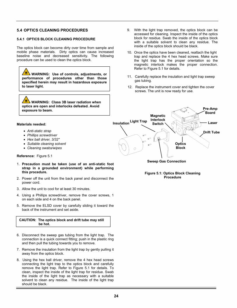
5.4 OPTICS CLEANING PROCEDURES
5.4.1 OPTICS BLOCK CLEANING PROCEDURE
The optics block can become dirty over time from sample and mobile phase materials. Dirty optics can cause increased baseline noise and decreased sensitivity. The following procedure can be used to clean the optics block. Materials needed:
• Anti-static strap • Phillips screwdriver • Hex ball driver, 3/32" • Suitable cleaning solvent • Cleaning swabs/wipes
Reference: Figure 5.1 1. Precaution must be taken (use of an anti-static foot
strap in a grounded environment) while performing this procedure.
2. Power off the unit from the back panel and disconnect the power cord.
3. Allow the unit to cool for at least 30 minutes.
4. Using a Phillips screwdriver, remove the cover screws, 1 on each side and 4 on the back panel.
5. Remove the ELSD cover by carefully sliding it toward the back of the instrument and set aside.
6. Disconnect the sweep gas tubing from the light trap. The connection is a quick connect fitting; push in the plastic ring and then pull the tubing towards you to remove.
7. Remove the insulation from the light trap by gently pulling it away from the optics block.
8. Using the hex ball driver, remove the 4 hex head screws connecting the light trap to the optics block and carefully remove the light trap. Refer to Figure 5.1 for details. To clean, inspect the inside of the light trap for residue. Swab the inside of the light trap as necessary with a suitable solvent to clean any residue. The inside of the light trap should be black.
9. With the light trap removed, the optics block can be accessed for cleaning. Inspect the inside of the optics block for residue. Swab the inside of the optics block with a suitable solvent to clean any residue. The inside of the optics block should be black.
10. Once the optics have been cleaned, reattach the light trap and replace the 4 hex head screws. Make sure the light trap has the proper orientation so the magnetic interlock makes the proper connection. Refer to Figure 5.1 for details.
11. Carefully replace the insulation and light trap sweep
gas tubing.
12. Replace the instrument cover and tighten the cover screws. The unit is now ready for use.
Light Trap
Sweep Gas Connection
Optics Block
Drift Tube
Laser
Pre-Amp Board
Magnetic InterlockSwitch
Figure 5.1: Optics Block Cleaning Procedure
Insulation
CAUTION: The optics block and drift tube may still be hot.
WARNING: Class 3B laser radiation when optics are open and interlocks defeated. Avoid exposure to beam.
WARNING: Use of controls, adjustments, orperformance of procedures other than thosespecified herein may result in hazardous exposureto laser light.
25
5.4.2 LASER WINDOW CLEANING PROCEDURE
Materials Needed:
• Anti-static strap • Phillips screwdriver • Hex ball driver, 3/32" • HPLC grade acetone • Cleaning wipes
References: Figure 5.2 and Figure 5.3 1. Precaution must be taken (use of an anti-static foot
strap in a grounded environment) while performing this procedure.
2. Power off the unit from the back panel and disconnect the power cord.
3. Allow the unit to cool for at least 30 minutes.
4. Using a Phillips screwdriver, remove the cover screws, 1 on each side and 4 on the back panel.
5. Remove the ELSD cover by carefully sliding it toward the back of the instrument and set it aside.
6. Remove the 4 screws connecting the laser to the optics mount using the hex ball driver and remove the laser. Allow the laser to hang inside the unit.
7. Remove the 4 screws on the optics mount using the hex ball driver and remove the optics mount.
8. Remove the laser window. Clean the window with acetone and cleaning wipes until no residue remains.
9. Replace the laser window.
10. Reattach the optics mount.
11. Reconnect the laser. Make sure the laser is oriented so the magnetic interlock makes the proper connection. 12. Replace the instrument cover and tighten the cover screws. The unit is now ready for use.
5.4.3 PHOTODIODE CLEANING PROCEDURE
Materials Needed:
• Anti-static strap • Phillips screwdriver • HPLC grade acetone • Cleaning wipes
References: Figure 5.2 and Figure 5.3 1. Precaution must be taken (use of an anti-static foot
strap in a grounded environment) while performing this procedure.
2. Power off the unit from the back panel and disconnect the power cord.
3. Allow the unit to cool for at least 30 minutes.
4. Using a Phillips screwdriver, remove the cover screws, 1 on each side and 4 on the back panel.
5. Remove the ELSD cover by carefully sliding it toward the back of the instrument and set it aside.
6. Disconnect the ribbon cable from the preamp board. Allow it to hang inside the unit.
7. Remove the 4 preamp cover screws using the Phillips screwdriver and remove the preamp cover.
8. Remove the preamp board screws using the Phillips screwdriver and remove the preamp board.
9. Flip the preamp board to access the photodiode sensor. Use acetone and cleaning wipes to clean the surface of the photodiode until there is no visible residue.
10. Replace the preamp board and preamp screws.
11. Replace the preamp cover and preamp cover screws.
12. Reconnect the ribbon cable to the preamp board.
13. Replace the instrument cover and tighten the cover screws. The unit is now ready for use.
CAUTION: The optics block and drift tube may still be hot.
CAUTION: The optics block and drift tube may still be hot.
WARNING: Use of controls, adjustments, orperformance of procedures other than thosespecified herein may result in hazardous exposureto laser light.
WARNING: Class 3B laser radiation when optics are open and interlocks defeated. Avoid exposure to beam.
WARNING: Use of controls, adjustments, orperformance of procedures other than thosespecified herein may result in hazardous exposureto laser light.
WARNING: Class 3B laser radiation when optics are open and interlocks defeated. Avoid exposure to beam.
26
5.4.4 PRE-AMP LENS ASSEMBLY CLEANING PROCEDURE
Materials Needed:
• Anti-static strap • Phillips screwdriver • Hex ball driver, 3/32” • Hex ball driver, 7/64” • HPLC grade acetone • Cleaning wipes
References: Figure 5.2 and Figure 5.4 1. Precaution must be taken (use of an anti-static foot
strap in a grounded environment) while performing this procedure.
2. Power off the unit from the back panel and disconnect the power cord.
3. Allow the unit to cool for at least 30 minutes.
4. Using a Phillips screwdriver, remove the cover screws, 1 on each side and 4 on the back panel.
5. Remove the ELSD cover by carefully sliding it toward the back of the instrument and set it aside.
6. Disconnect the ribbon cable from the preamp board. Allow it to hang inside the unit.
7. Remove the 4 preamp cover screws using the Phillips screwdriver and remove the preamp cover.
8. Remove the 4 preamp board screws using the Phillips screwdriver and remove the preamp board. Set the preamp board aside.
9. Remove the 4 preamp mount plate screws using the Phillips screwdriver and remove the preamp mounting plate.
10. Remove the 4 screws connected to the preamp lens assembly using the 7/64” hex driver.
11. Flip the preamp lens assembly and remove the 4 screws using the 3/32” hex driver.
12. Remove the lens and clean with acetone and cleaning wipes until no fingerprints, smudges, or dirt remain.
13. Carefully replace the lens; make sure the curved surface faces toward the aperture.
14. Replace the 4 screws to the preamp lens assembly.
15. Replace the preamp lens assembly onto the optics block with the 4 screws. 16. Replace the preamp mount plate onto the optics block with the 4 screws. 17. Replace the preamp board and the 4 preamp board screws. 18. Replace the preamp board cover and 4 preamp board cover screws. 19. Reconnect the ribbon cable to the preamp board. 20. Replace the instrument cover and tighten the cover screws. The unit is now ready for use.
CAUTION: The optics block and drift tube may still be hot.
WARNING: Class 3B laser radiation when optics are open and interlocks defeated. Avoid exposure to beam.
WARNING: Use of controls, adjustments, orperformance of procedures other than thosespecified herein may result in hazardous exposureto laser light.
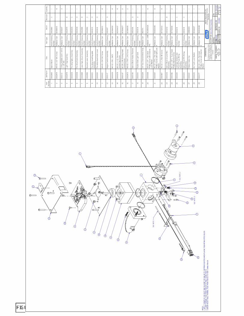
NOTE
S:1.
APPL
Y "C
HEM
PLEX
138
1 HE
AT S
INK
SILI
CONE
" OR
SIM
ILAR
TO
CART
RIDG
E HE
ATER
S W
HEN
PLAC
ING
THEM
WIT
HIN
OPTI
CS B
LOCK
.2.
CLA
MP
THER
MAL
FU
SE F
ROM
ITEM
25
TO IT
EM 1
USI
NG IT
EM 1
9.3.
MO
UNT
RES
ETTA
BLE
THER
MAL
FU
SE F
ROM
ITEM
25
TO IT
EM 1
USI
NG IT
EM 2
9.
09/1
4/06
Optic
s Bl
ock
Asse
mbl
y
0002
882
D
DESC
RIPT
ION:
DATE
:GE
NERA
L TO
LERA
NCES
DEC
IMAL
: ±.0
02"
FRAC
TION
AL:
± 1/
64"
ANGU
LAR:
±1/
2º
APPR
OVED
:DR
AWN:
CONF
IDEN
TIAL
:
This
dra
win
g is
the
prop
erty
of
Allte
chAs
soci
ates
, Inc
. An
y re
prod
uctio
ns o
rm
odifi
catio
ns o
f thi
s dr
awin
g or
its
cont
ents
with
out c
onse
nt o
f Al
ltech
ispr
ohib
ited.
Allte
ch A
ssoc
iate
s, In
c.20
51 W
auke
gan
Road
, Dee
rfie
ld, IL
600
15(8
47) 9
48-8
600
MAT
ERIA
L:
DRAW
ING
NO:
REV
BBSH
EET
1 OF
1SC
ALE:
1=1
.33
SIZE
D
P/N:
ksch
mitt
27
16
2
4
7
8
5
6
18
9
10
11
13
20
21
12
1724
26
2523
19
14
15
SEE
NOTE
1
22
3
28
SEE
NOTE
2
1
29
SEE
NOTE
3
Item
Num
ber
CM P
art
#Ti
tleRe
f. Ty
peRe
f. #
Revi
sion
Quan
tity
100
0288
3Op
tics
Blo
ckAl
ltech
Dra
win
gNu
mbe
r00
0288
3C
1
200
0247
4#
4-40
x 1
/2" S
HC S
crew
McM
aste
r-Ca
rr#
9219
6A11
0-
4
300
0311
3O-
Ring
AS5
68A-
024
(1 1/
8" ID
x 1
1/4"
OD)
McM
aste
r-Ca
rr#
9319
k147
-3
400
0297
9Li
ght
Trap
Ass
embl
yAl
ltech
Dra
win
gNu
mbe
r00
0297
9B
1
500
0300
5Pr
e-Am
p O
ptic
s As
sem
bly
Allte
ch D
raw
ing
Num
ber
0003
005
C1
600
0300
6Pr
e-Am
p Bo
ard
Asse
mbl
yAl
ltech
Dra
win
gNu
mbe
r00
0300
6D
1
700
0298
8La
ser
Opt
ic M
ount
Ass
embl
yAl
ltech
Dra
win
gNu
mbe
r00
0298
8B
1
800
0299
2M
ount
ed L
aser
Ass
embl
yAl
ltech
Dra
win
gNu
mbe
r00
0299
2C
1
900
0301
5Pr
e-Am
p m
ount
ing
plat
eas
sem
bly
Allte
ch D
raw
ing
Num
ber
0003
015
D1
1000
0301
6Pr
e-am
p sh
eetm
etal
cov
erAl
ltech
Dra
win
gNu
mbe
r00
0301
6D
1
1100
0302
1#
4-40
x 3
/4" S
HC S
crew
McM
aste
r-Ca
rr#
9219
6A11
3-
4
1200
0311
7M
agne
t Sw
itch
Asse
mbl
yAl
ltech
Dra
win
gNu
mbe
r00
0311
7O
1
1300
0303
0#
6-32
x 5
/8 L
SHC
SM
cMas
ter-
Carr
#92
196A
150
-4
1400
0327
6#
6-32
x 1
1/2
" Fla
t Hea
dSo
cket
Cap
Scr
ewM
cMas
ter-
Carr
#92
210A
157
-4
1500
0313
7#
2-56
x 1
/4L
Bind
ing
Head
Slot
ted
Scre
wM
cMas
ter-
Carr
#91
793A
077
-2
1600
0247
3#
4-40
x 7
/16"
L S
HC S
crew
McM
aste
r-Ca
rr#
9219
6A10
9-
2
1700
0313
6Op
tics
Blo
ck H
eate
r Re
tain
erAl
ltech
Dra
win
gNu
mbe
r00
0313
6O
1
1800
0301
4Ru
bber
Dis
k Li
ght S
eal
Allte
ch D
raw
ing
Num
ber
0003
014
A1
1900
0326
41/
8" T
wo
Chan
nel M
etal
Str
apM
cMas
ter-
Carr
#94
31T1
1-
1
2000
0306
6#
4-40
x 1
/4" L
Pan
Hea
dPh
illip
s Sc
rew
with
Ext
erna
lLo
ck W
ashe
r
McM
aste
r- C
ARR
P/N
9534
5A42
6-
4
2100
0306
7#
6-32
x 5
/16
L Pa
n He
adPh
illip
s Sc
rew
with
Spl
it Lo
ckW
ashe
r
McM
aste
r-Ca
rr#
9340
5A14
5-
4
2200
0196
7#
6-32
x 1
L P
an H
D Sc
rew
McM
aste
r-Ca
rr#
9177
2A15
3-
4
2300
0323
2Op
tics
Blo
ck G
roun
d W
ireAs
sem
bly
Allte
ch D
raw
ing
Num
ber
0003
232
B1
2400
0318
6#
6-32
x 3
/8" L
Tru
ss H
ead
Phill
ips
Mac
hine
Scr
ewM
cMas
ter-
Carr
#91
770A
146
-2
2500
0321
8Ca
rtrid
ge H
eate
rs a
ndTh
erm
al F
use
Wiri
ngAs
sem
bly
Allte
ch D
raw
ing
Num
ber
0003
218
C1
2600
0321
4Op
tics
Blo
ck R
TD W
iring
Asse
mbl
yAl
ltech
Dra
win
gNu
mbe
r00
0321
4C
1
2700
0022
1Ri
bbon
Cab
le C
lipM
cMas
ter-
Carr
#69
965K
91-
1
2800
0021
6#
6 To
oth
Lock
Was
her
McM
aste
r-Ca
rr#
9111
4A00
7-
1
2900
0317
7#
6-32
x 3
/8 L
Pan
Hea
dPh
illip
s Sc
rew
with
Inte
rnal
Was
her
McM
aste
r-Ca
rr#
9040
3A14
6-
1

NOTE
S:
09/1
4/06
Lase
r Op
tic M
ount
Ass
embl
y
0002
988
C
DESC
RIPT
ION:
DATE
:AP
PROV
ED:
DRAW
N:
CONF
IDEN
TIAL
:
This
dra
win
g is
the
prop
erty
of
Allte
chAs
soci
ates
, Inc
. An
y re
prod
uctio
ns o
rm
odifi
catio
ns o
f th
is d
raw
ing
or it
sco
nten
ts w
ithou
t con
sent
of
Allte
ch is
proh
ibite
d.
Allte
ch A
ssoc
iate
s, In
c.20
51 W
auke
gan
Road
, Dee
rfie
ld, I
L 60
015
(847
) 948
-860
0
MAT
ERIA
L:
DRAW
ING
NO:
REV
WM
SHEE
T1
OF 1
SCAL
E: 1
= 1
SIZE
B
P/N:
BYGE
NERA
L TO
LERA
NCES
DEC
IMAL
: .X
X ±.0
10";
.XXX
±.0
05"
FRAC
TION
AL:
± 1/
64"
ANGU
LAR:
±1/
2º63
UNL
ESS
OTHE
RWIS
E SP
ECIF
IED
Item
Num
ber
CM P
art #
Title
Ref.
Type
Ref.
#Re
visi
onQu
antit
y
100
0247
2Ø
5/16
Ape
rtur
eAl
ltech
Dra
win
g Nu
mbe
r00
0247
2B
1
200
0247
1Ø
1/4
Aper
ture
Allte
ch D
raw
ing
Num
ber
0002
471
B1
300
0249
33/
4 Re
tain
ing
Ring
McM
aste
r-Ca
rr #
9158
0A18
1-
2
400
0248
7Op
tical
Win
dow
Sea
lAl
ltech
Par
t Num
ber
0002
487
A1
500
0248
8O
ptic
al W
indo
wEd
mun
d45
639
-1
600
0247
3#
4-40
x 7
/16"
L S
HC S
crew
McM
aste
r-Ca
rr #
9219
6A10
9-
2
700
0311
7M
agne
t Sw
itch
Asse
mbl
yAl
ltech
Dra
win
g Nu
mbe
r00
0311
7O
1
800
0250
9#
4-40
SHC
S x
5/16
LM
cMas
ter-
Carr
#92
196A
107
-4
900
0332
0W
indo
w L
ock
Inse
rtAl
ltech
Dra
win
g Nu
mbe
r00
0332
0O
1
1000
0332
1#
2-56
x 1
/4"L
SHC
SM
cMas
ter-
Carr
#92
196A
077
-3
1100
0299
0La
ser
Opt
ic M
ount
Allte
ch D
raw
ing
Num
ber
0002
990
A1
1200
0298
9La
ser
Posi
tioni
ng S
pace
rAl
ltech
Dra
win
g Nu
mbe
r00
0298
9B
1
1300
0302
0M
ale
Conn
ecto
r 10
-32
Thre
ad to
1/8
Tub
e -
Push
-In
Fitt
ing
Park
er #
68M
L-2-
0-
1
2
1
6
4
5
3
8
12
11
13
7
9
10
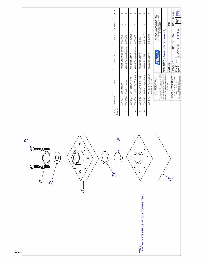
NOTE
S:1.
POSI
TION
CU
RVE
SURF
ACE
OF IT
EM 6
TOW
ARDS
ITEM
1.
09/1
4/06
Pre-
Amp
Optic
s As
sem
bly
0003
005
C
DESC
RIPT
ION:
DATE
:AP
PROV
ED:
DRAW
N:
CONF
IDEN
TIAL
:
This
dra
win
g is
the
prop
erty
of
Allte
chAs
soci
ates
, Inc
. An
y re
prod
uctio
ns o
rm
odifi
catio
ns o
f th
is d
raw
ing
or it
sco
nten
ts w
ithou
t con
sent
of
Allte
ch is
proh
ibite
d.
Allte
ch A
ssoc
iate
s, In
c.20
51 W
auke
gan
Road
, Dee
rfie
ld, I
L 60
015
(847
) 948
-860
0
MAT
ERIA
L:
DRAW
ING
NO:
REV
WM
SHEE
T1
OF 1
SCAL
E: 1
= 1
SIZE
B
P/N:
BYGE
NERA
L TO
LERA
NCES
DEC
IMAL
: .X
X ±.0
10";
.XXX
±.0
05"
FRAC
TION
AL:
± 1/
64"
ANGU
LAR:
±1/
2º63
UNL
ESS
OTHE
RWIS
E SP
ECIF
IED
4
6
3
1
2
5Ite
mNu
mbe
rCM
Par
t #Ti
tleRe
f. Ty
peRe
f. #
Revi
sion
Quan
tity
100
0300
3Le
ns M
ount
Allte
ch D
raw
ing
Num
ber
0003
003
C1
200
0300
4Pr
e-Am
p M
ount
Allte
ch D
raw
ing
Num
ber
0003
004
D1
300
0249
33/
4 Re
tain
ing
Ring
McM
aste
r-Ca
rr #
9158
0A18
1-
1
400
0006
8.3
6 ID
x .7
4 O
D Ap
ertu
reAl
ltech
Dra
win
g Nu
mbe
r00
0006
8B
1
500
0313
5AS
568A
-114
O-R
ing
McM
aste
r-Ca
rr #
9319
k24
-1
600
0199
7As
pher
ic G
lass
Len
sM
elle
s Gr
iot P
/N01
-LAG
-003
-1
700
0317
2#
6-32
X 1
/2 L
Soc
ket
Head
Cap
Scr
ewM
cMas
ter-
Carr
#92
196A
148
-4
7
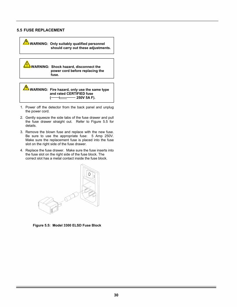
30
5.5 FUSE REPLACEMENT
1. Power off the detector from the back panel and unplug the power cord.
2. Gently squeeze the side tabs of the fuse drawer and pull the fuse drawer straight out. Refer to Figure 5.5 for details.
3. Remove the blown fuse and replace with the new fuse. Be sure to use the appropriate fuse: 5 Amp 250V. Make sure the replacement fuse is placed into the fuse slot on the right side of the fuse drawer.
4. Replace the fuse drawer. Make sure the fuse inserts into the fuse slot on the right side of the fuse block. The correct slot has a metal contact inside the fuse block.
Figure 5.5: Model 3300 ELSD Fuse Block
WARNING: Only suitably qualified personnel should carry out these adjustments.
WARNING: Shock hazard, disconnect the power cord before replacing the fuse.
WARNING: Fire hazard, only use the same type and rated CERTIFIED fuse ( 250V 5A F).
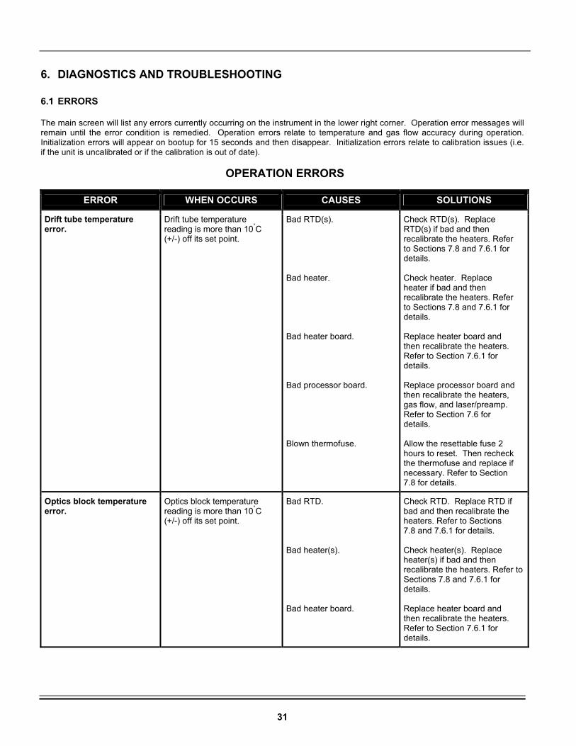
31
6. DIAGNOSTICS AND TROUBLESHOOTING
6.1 ERRORS
The main screen will list any errors currently occurring on the instrument in the lower right corner. Operation error messages will remain until the error condition is remedied. Operation errors relate to temperature and gas flow accuracy during operation. Initialization errors will appear on bootup for 15 seconds and then disappear. Initialization errors relate to calibration issues (i.e. if the unit is uncalibrated or if the calibration is out of date).
OPERATION ERRORS
ERROR WHEN OCCURS CAUSES SOLUTIONS
Drift tube temperature error.
Drift tube temperature reading is more than 10°C (+/-) off its set point.
Bad RTD(s). Bad heater. Bad heater board. Bad processor board. Blown thermofuse.
Check RTD(s). Replace RTD(s) if bad and then recalibrate the heaters. Refer to Sections 7.8 and 7.6.1 for details. Check heater. Replace heater if bad and then recalibrate the heaters. Refer to Sections 7.8 and 7.6.1 for details. Replace heater board and then recalibrate the heaters. Refer to Section 7.6.1 for details. Replace processor board and then recalibrate the heaters, gas flow, and laser/preamp. Refer to Section 7.6 for details. Allow the resettable fuse 2 hours to reset. Then recheck the thermofuse and replace if necessary. Refer to Section 7.8 for details.
Optics block temperature error.
Optics block temperature reading is more than 10°C (+/-) off its set point.
Bad RTD. Bad heater(s). Bad heater board.
Check RTD. Replace RTD if bad and then recalibrate the heaters. Refer to Sections 7.8 and 7.6.1 for details. Check heater(s). Replace heater(s) if bad and then recalibrate the heaters. Refer to Sections 7.8 and 7.6.1 for details. Replace heater board and then recalibrate the heaters. Refer to Section 7.6.1 for details.

32
OPERATION ERRORS (continued)
ERROR WHEN OCCURS CAUSES SOLUTIONS
Optics block temperature error (continued).
Optics block temperature reading is more than 10°C (+/-) off its set point.
Bad processor board. Blown thermofuse.
Replace processor board and then recalibrate the heaters, gas flow, and laser/preamp. Refer to Section 7.6 for details. Allow the resettable fuse 2 hours to reset. Then recheck the thermofuse and replace if necessary. Refer to Section 7.8 for details.
Gas flow error.
Gas flow reading is more than 0.3L/min (+/-) off its set point.
Gas source may be low or empty. Regulator pressure setting is too low. Nebulizer may be blocked. Gas leaks may exist inside unit. Bad gas flow valve and/or flow meter. Bad processor board.
Check gas source and replace if necessary. Adjust regulator pressure to 65-80psig. Clean nebulizer. Refer to Section 5.2 for details. Check gas flow path for leaks. Replace flow meter and/or valve, and then recalibrate the gas flow. Refer to Section 7.6.2 for details. Replace processor board and then recalibrate the heaters, gas flow, and laser/preamp. Refer to Section 7.6 for details.
Inlet gas pressure is low. Inlet gas pressure is lower than 40 psig.
Regulator pressure setting is too low. Gas source may be low or empty. Gas leaks may exist inside unit. Bad processor board. Bad pressure switch.
Adjust regulator pressure to 65-80psig. Replace gas source if necessary. Check gas flow path for leaks and remedy. Replace processor board and then recalibrate the heaters, gas flow, and laser/preamp. Refer to Section 7.6 for details. Replace pressure switch.
Any errors not included in this list.
Contact Grace/Alltech.

33
INITIALIZATION ERRORS
ERROR WHEN OCCURS CAUSES SOLUTIONS
The following errors occurred during initialization: The device has not been configured. Device heater, gas flow, and/or laser have not been calibrated. Please contact a technical service representative to recalibrate. Error encountered while setting temperature, gas flow, or gain.
Laser/preamp, gas flow, and/or heaters have not been calibrated.
Calibrate the heaters, gas flow, and/or laser/preamp. Refer to Section 7.6 for calibration procedures.
The following errors occurred during initialization: Device heater, gas flow, and/or laser calibration is out of date (last calibrated mm/dd/yyyy hh:mm:ss AM/PM). Please contact a technical service to recalibrate.
Unit requires its yearly recalibration.
Recalibrate the heaters, gas flow, and/or laser/preamp as needed. Refer to Section 7.6 for calibration procedures.
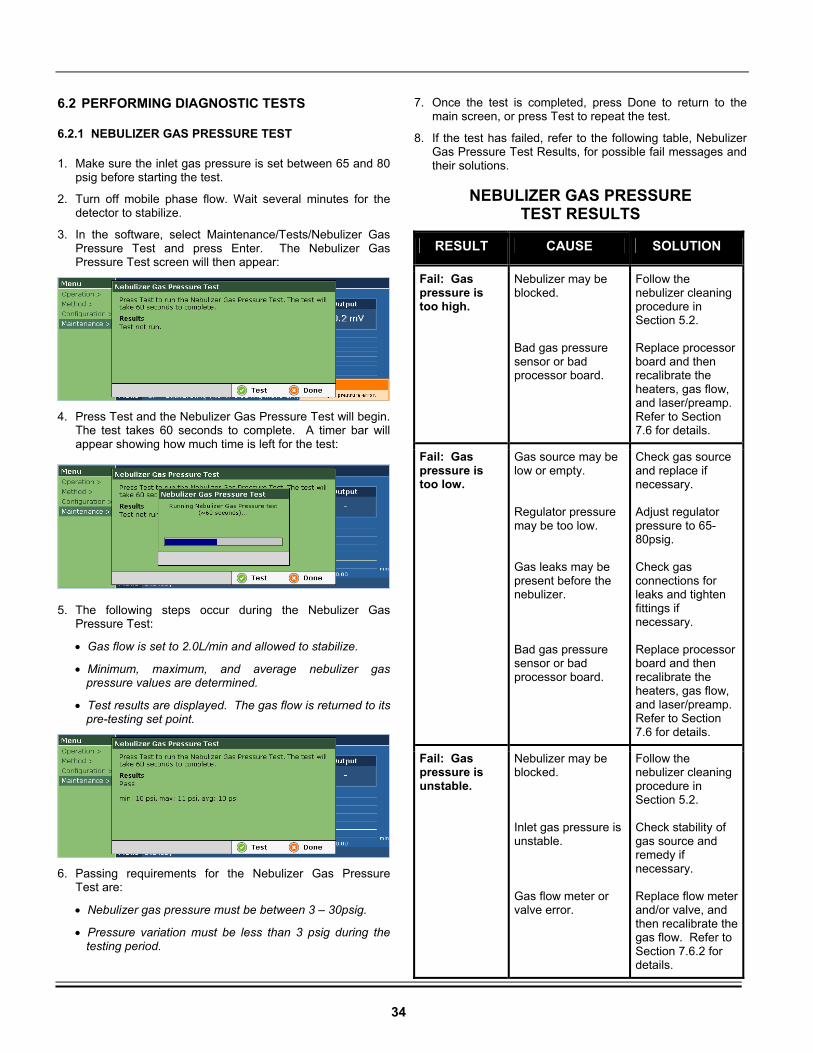
34
6.2 PERFORMING DIAGNOSTIC TESTS
6.2.1 NEBULIZER GAS PRESSURE TEST
1. Make sure the inlet gas pressure is set between 65 and 80 psig before starting the test.
2. Turn off mobile phase flow. Wait several minutes for the detector to stabilize.
3. In the software, select Maintenance/Tests/Nebulizer Gas Pressure Test and press Enter. The Nebulizer Gas Pressure Test screen will then appear:
4. Press Test and the Nebulizer Gas Pressure Test will begin. The test takes 60 seconds to complete. A timer bar will appear showing how much time is left for the test:
5. The following steps occur during the Nebulizer Gas
Pressure Test:
• Gas flow is set to 2.0L/min and allowed to stabilize.
• Minimum, maximum, and average nebulizer gas pressure values are determined.
• Test results are displayed. The gas flow is returned to its pre-testing set point.
6. Passing requirements for the Nebulizer Gas Pressure
Test are:
• Nebulizer gas pressure must be between 3 – 30psig.
• Pressure variation must be less than 3 psig during the testing period.
7. Once the test is completed, press Done to return to the main screen, or press Test to repeat the test.
8. If the test has failed, refer to the following table, Nebulizer Gas Pressure Test Results, for possible fail messages and their solutions.
NEBULIZER GAS PRESSURE
TEST RESULTS
RESULT CAUSE SOLUTION
Fail: Gas pressure is too high.
Nebulizer may be blocked. Bad gas pressure sensor or bad processor board.
Follow the nebulizer cleaning procedure in Section 5.2. Replace processor board and then recalibrate the heaters, gas flow, and laser/preamp. Refer to Section 7.6 for details.
Fail: Gas pressure is too low.
Gas source may be low or empty. Regulator pressure may be too low. Gas leaks may be present before the nebulizer. Bad gas pressure sensor or bad processor board.
Check gas source and replace if necessary. Adjust regulator pressure to 65-80psig. Check gas connections for leaks and tighten fittings if necessary. Replace processor board and then recalibrate the heaters, gas flow, and laser/preamp. Refer to Section 7.6 for details.
Fail: Gas pressure is unstable.
Nebulizer may be blocked. Inlet gas pressure is unstable. Gas flow meter or valve error.
Follow the nebulizer cleaning procedure in Section 5.2. Check stability of gas source and remedy if necessary. Replace flow meter and/or valve, and then recalibrate the gas flow. Refer to Section 7.6.2 for details.
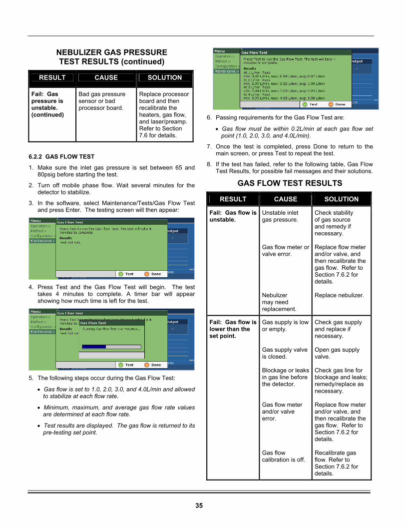
35
NEBULIZER GAS PRESSURE TEST RESULTS (continued)
RESULT CAUSE SOLUTION
Fail: Gas pressure is unstable. (continued)
Bad gas pressure sensor or bad processor board.
Replace processor board and then recalibrate the heaters, gas flow, and laser/preamp. Refer to Section 7.6 for details.
6.2.2 GAS FLOW TEST
1. Make sure the inlet gas pressure is set between 65 and 80psig before starting the test.
2. Turn off mobile phase flow. Wait several minutes for the detector to stabilize.
3. In the software, select Maintenance/Tests/Gas Flow Test and press Enter. The testing screen will then appear:
4. Press Test and the Gas Flow Test will begin. The test
takes 4 minutes to complete. A timer bar will appear showing how much time is left for the test.
5. The following steps occur during the Gas Flow Test:
• Gas flow is set to 1.0, 2.0, 3.0, and 4.0L/min and allowed to stabilize at each flow rate.
• Minimum, maximum, and average gas flow rate values are determined at each flow rate.
• Test results are displayed. The gas flow is returned to its pre-testing set point.
6. Passing requirements for the Gas Flow Test are:
• Gas flow must be within 0.2L/min at each gas flow set point (1.0, 2.0, 3.0, and 4.0L/min).
7. Once the test is completed, press Done to return to the main screen, or press Test to repeat the test.
8. If the test has failed, refer to the following table, Gas Flow Test Results, for possible fail messages and their solutions.
GAS FLOW TEST RESULTS
RESULT CAUSE SOLUTION
Fail: Gas flow is unstable.
Unstable inlet gas pressure. Gas flow meter or valve error. Nebulizer may need replacement.
Check stability of gas source and remedy if necessary. Replace flow meter and/or valve, and then recalibrate the gas flow. Refer to Section 7.6.2 for details. Replace nebulizer.
Fail: Gas flow is lower than the set point.
Gas supply is low or empty. Gas supply valve is closed. Blockage or leaks in gas line before the detector. Gas flow meter and/or valve error. Gas flow calibration is off.
Check gas supply and replace if necessary. Open gas supply valve. Check gas line for blockage and leaks; remedy/replace as necessary. Replace flow meter and/or valve, and then recalibrate the gas flow. Refer to Section 7.6.2 for details. Recalibrate gas flow. Refer to Section 7.6.2 for details.
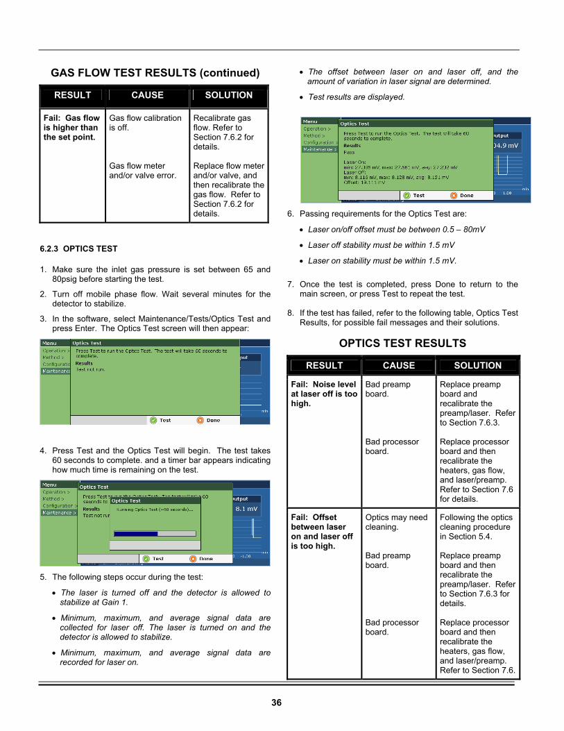
36
GAS FLOW TEST RESULTS (continued)
RESULT CAUSE SOLUTION
Fail: Gas flow is higher than the set point.
Gas flow calibration is off. Gas flow meter and/or valve error.
Recalibrate gas flow. Refer to Section 7.6.2 for details. Replace flow meter and/or valve, and then recalibrate the gas flow. Refer to Section 7.6.2 for details.
6.2.3 OPTICS TEST
1. Make sure the inlet gas pressure is set between 65 and 80psig before starting the test.
2. Turn off mobile phase flow. Wait several minutes for the detector to stabilize.
3. In the software, select Maintenance/Tests/Optics Test and press Enter. The Optics Test screen will then appear:
4. Press Test and the Optics Test will begin. The test takes 60 seconds to complete. and a timer bar appears indicating how much time is remaining on the test.
5. The following steps occur during the test:
• The laser is turned off and the detector is allowed to stabilize at Gain 1.
• Minimum, maximum, and average signal data are collected for laser off. The laser is turned on and the detector is allowed to stabilize.
• Minimum, maximum, and average signal data are recorded for laser on.
• The offset between laser on and laser off, and the amount of variation in laser signal are determined.
• Test results are displayed.
6. Passing requirements for the Optics Test are:
• Laser on/off offset must be between 0.5 – 80mV
• Laser off stability must be within 1.5 mV
• Laser on stability must be within 1.5 mV.
7. Once the test is completed, press Done to return to the
main screen, or press Test to repeat the test. 8. If the test has failed, refer to the following table, Optics Test
Results, for possible fail messages and their solutions.
OPTICS TEST RESULTS
RESULT CAUSE SOLUTION
Fail: Noise level at laser off is too high.
Bad preamp board. Bad processor board.
Replace preamp board and recalibrate the preamp/laser. Refer to Section 7.6.3. Replace processor board and then recalibrate the heaters, gas flow, and laser/preamp. Refer to Section 7.6 for details.
Fail: Offset between laser on and laser off is too high.
Optics may need cleaning. Bad preamp board. Bad processor board.
Following the optics cleaning procedure in Section 5.4. Replace preamp board and then recalibrate the preamp/laser. Refer to Section 7.6.3 for details. Replace processor board and then recalibrate the heaters, gas flow, and laser/preamp. Refer to Section 7.6.
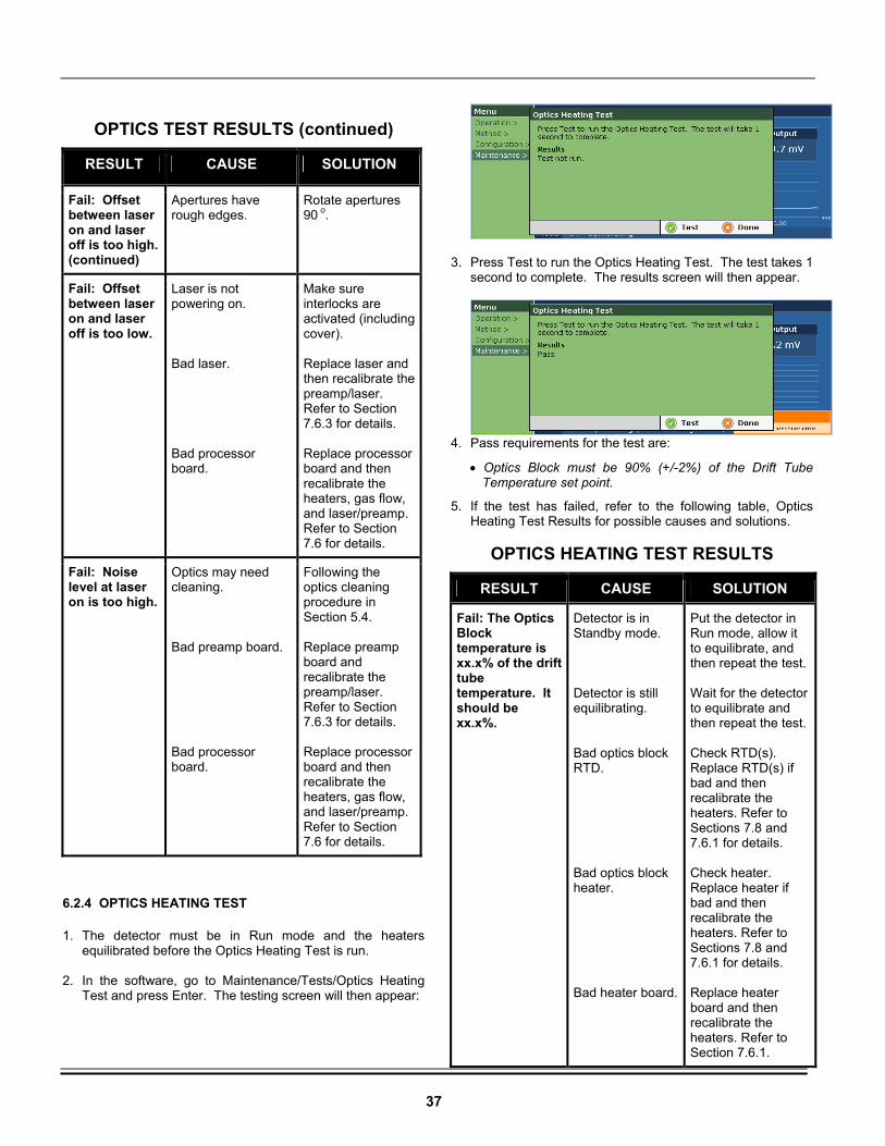
37
OPTICS TEST RESULTS (continued)
RESULT CAUSE SOLUTION
Fail: Offset between laser on and laser off is too high. (continued)
Apertures have rough edges.
Rotate apertures 90 o.
Fail: Offset between laser on and laser off is too low.
Laser is not powering on. Bad laser. Bad processor board.
Make sure interlocks are activated (including cover). Replace laser and then recalibrate the preamp/laser. Refer to Section 7.6.3 for details. Replace processor board and then recalibrate the heaters, gas flow, and laser/preamp. Refer to Section 7.6 for details.
Fail: Noise level at laser on is too high.
Optics may need cleaning. Bad preamp board. Bad processor board.
Following the optics cleaning procedure in Section 5.4. Replace preamp board and recalibrate the preamp/laser. Refer to Section 7.6.3 for details. Replace processor board and then recalibrate the heaters, gas flow, and laser/preamp. Refer to Section 7.6 for details.
6.2.4 OPTICS HEATING TEST
1. The detector must be in Run mode and the heaters equilibrated before the Optics Heating Test is run.
2. In the software, go to Maintenance/Tests/Optics Heating
Test and press Enter. The testing screen will then appear:
3. Press Test to run the Optics Heating Test. The test takes 1
second to complete. The results screen will then appear.
4. Pass requirements for the test are:
• Optics Block must be 90% (+/-2%) of the Drift Tube Temperature set point.
5. If the test has failed, refer to the following table, Optics Heating Test Results for possible causes and solutions.
OPTICS HEATING TEST RESULTS
RESULT CAUSE SOLUTION
Fail: The Optics Block temperature is xx.x% of the drift tube temperature. It should be xx.x%.
Detector is in Standby mode. Detector is still equilibrating. Bad optics block RTD. Bad optics block heater. Bad heater board.
Put the detector in Run mode, allow it to equilibrate, and then repeat the test. Wait for the detector to equilibrate and then repeat the test. Check RTD(s). Replace RTD(s) if bad and then recalibrate the heaters. Refer to Sections 7.8 and 7.6.1 for details. Check heater. Replace heater if bad and then recalibrate the heaters. Refer to Sections 7.8 and 7.6.1 for details. Replace heater board and then recalibrate the heaters. Refer to Section 7.6.1.
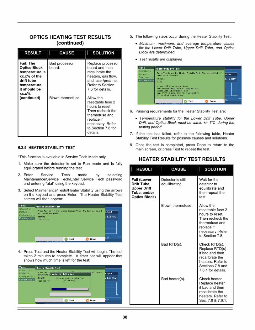
38
OPTICS HEATING TEST RESULTS
(continued)
RESULT CAUSE SOLUTION
Fail: The Optics Block temperature is xx.x% of the drift tube temperature. It should be xx.x%. (continued)
Bad processor board. Blown thermofuse.
Replace processor board and then recalibrate the heaters, gas flow, and laser/preamp. Refer to Section 7.6 for details. Allow the resettable fuse 2 hours to reset. Then recheck the thermofuse and replace if necessary. Refer to Section 7.8 for details.
6.2.5 HEATER STABILITY TEST
*This function is available in Service Tech Mode only.
1. Make sure the detector is set to Run mode and is fully equilibrated before running the test.
2. Enter Service Tech mode by selecting Maintenance/Service Tech/Enter Service Tech password and entering “atat” using the keypad.
3. Select Maintenance/Tests/Heater Stability using the arrows on the keypad and press Enter. The Heater Stability Test screen will then appear:
4. Press Test and the Heater Stability Test will begin. The test
takes 2 minutes to complete. A timer bar will appear that shows how much time is left for the test:
5. The following steps occur during the Heater Stability Test:
• Minimum, maximum, and average temperature values for the Lower Drift Tube, Upper Drift Tube, and Optics Block are determined.
• Test results are displayed
6. Passing requirements for the Heater Stability Test are:
• Temperature stability for the Lower Drift Tube, Upper Drift, and Optics Block must be within +/- 1oC during the testing period.
7. If the test has failed, refer to the following table, Heater Stability Test Results for possible causes and solutions.
8. Once the test is completed, press Done to return to the main screen, or press Test to repeat the test.
HEATER STABILITY TEST RESULTS
RESULT CAUSE SOLUTION
Fail (Lower Drift Tube, Upper Drift Tube, and/or Optics Block)
Detector is still equilibrating. Blown thermofuse. Bad RTD(s). Bad heater(s).
Wait for the detector to equilibrate and then repeat the test. Allow the resettable fuse 2 hours to reset. Then recheck the thermofuse and replace if necessary. Refer to Section 7.8. Check RTD(s). Replace RTD(s) if bad and then recalibrate the heaters. Refer to Sections 7.8 and 7.6.1 for details. Check heater. Replace heater if bad and then recalibrate the heaters. Refer to Sec. 7.8 & 7.6.1.
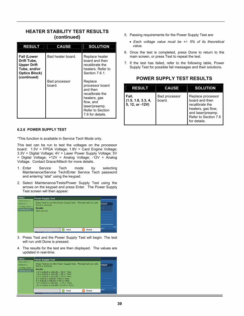
39
HEATER STABILITY TEST RESULTS (continued)
RESULT CAUSE SOLUTION
Fail (Lower Drift Tube, Upper Drift Tube, and/or Optics Block) (continued)
Bad heater board. Bad processor board.
Replace heater board and then recalibrate the heaters. Refer to Section 7.6.1. Replace processor board and then recalibrate the heaters, gas flow, and laser/preamp. Refer to Section 7.6 for details.
6.2.6 POWER SUPPLY TEST
*This function is available in Service Tech Mode only.
This test can be run to test the voltages on the processor board: 1.5V = FPGA Voltage; 1.8V = Card Engine Voltage; 3.3V = Digital Voltage; 4V = Laser Power Supply Voltage; 5V = Digital Voltage; +12V = Analog Voltage; -12V = Analog Voltage. Contact Grace/Alltech for more details.
1. Enter Service Tech mode by selecting Maintenance/Service Tech/Enter Service Tech password and entering “atat” using the keypad.
2. Select Maintenance/Tests/Power Supply Test using the arrows on the keypad and press Enter. The Power Supply Test screen will then appear:
3. Press Test and the Power Supply Test will begin. The test
will run until Done is pressed.
4. The results for the test are then displayed. The values are updated in real-time.
5. Passing requirements for the Power Supply Test are:
• Each voltage value must be +/- 5% of its theoretical value.
6. Once the test is completed, press Done to return to the main screen, or press Test to repeat the test.
7. If the test has failed, refer to the following table, Power Supply Test for possible fail messages and their solutions.
POWER SUPPLY TEST RESULTS
RESULT CAUSE SOLUTION
Fail. (1.5, 1.8, 3.3, 4, 5, 12, or -12V)
Bad processor board.
Replace processor board and then recalibrate the heaters, gas flow, and laser/preamp. Refer to Section 7.6 for details.
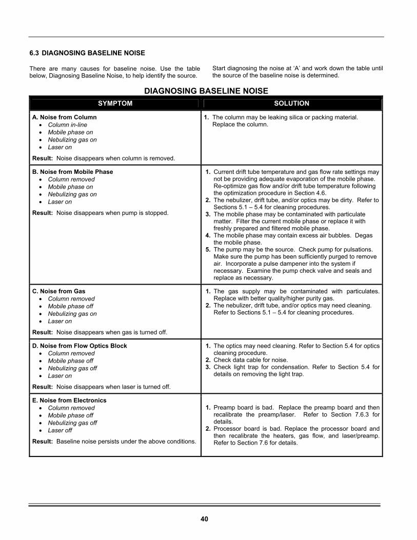
40
6.3 DIAGNOSING BASELINE NOISE
There are many causes for baseline noise. Use the table below, Diagnosing Baseline Noise, to help identify the source.
Start diagnosing the noise at ‘A’ and work down the table until the source of the baseline noise is determined.
DIAGNOSING BASELINE NOISE
SYMPTOM SOLUTION
A. Noise from Column • Column in-line • Mobile phase on • Nebulizing gas on • Laser on
Result: Noise disappears when column is removed.
1. The column may be leaking silica or packing material. Replace the column.
B. Noise from Mobile Phase • Column removed • Mobile phase on • Nebulizing gas on • Laser on
Result: Noise disappears when pump is stopped.
1. Current drift tube temperature and gas flow rate settings may not be providing adequate evaporation of the mobile phase. Re-optimize gas flow and/or drift tube temperature following the optimization procedure in Section 4.6.
2. The nebulizer, drift tube, and/or optics may be dirty. Refer to Sections 5.1 – 5.4 for cleaning procedures.
3. The mobile phase may be contaminated with particulate matter. Filter the current mobile phase or replace it with freshly prepared and filtered mobile phase.
4. The mobile phase may contain excess air bubbles. Degas the mobile phase.
5. The pump may be the source. Check pump for pulsations. Make sure the pump has been sufficiently purged to remove air. Incorporate a pulse dampener into the system if necessary. Examine the pump check valve and seals and replace as necessary.
C. Noise from Gas • Column removed • Mobile phase off • Nebulizing gas on • Laser on
Result: Noise disappears when gas is turned off.
1. The gas supply may be contaminated with particulates. Replace with better quality/higher purity gas.
2. The nebulizer, drift tube, and/or optics may need cleaning. Refer to Sections 5.1 – 5.4 for cleaning procedures.
D. Noise from Flow Optics Block • Column removed • Mobile phase off • Nebulizing gas off • Laser on
Result: Noise disappears when laser is turned off.
1. The optics may need cleaning. Refer to Section 5.4 for optics cleaning procedure.
2. Check data cable for noise. 3. Check light trap for condensation. Refer to Section 5.4 for
details on removing the light trap.
E. Noise from Electronics • Column removed • Mobile phase off • Nebulizing gas off • Laser off
Result: Baseline noise persists under the above conditions.
1. Preamp board is bad. Replace the preamp board and then
recalibrate the preamp/laser. Refer to Section 7.6.3 for details.
2. Processor board is bad. Replace the processor board and then recalibrate the heaters, gas flow, and laser/preamp. Refer to Section 7.6 for details.
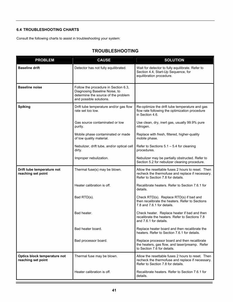
41
6.4 TROUBLESHOOTING CHARTS
Consult the following charts to assist in troubleshooting your system:
TROUBLESHOOTING
PROBLEM CAUSE SOLUTION
Baseline drift Detector has not fully equilibrated.
Wait for detector to fully equilibrate. Refer to Section 4.4, Start-Up Sequence, for equilibration procedure.
Baseline noise Follow the procedure in Section 6.3, Diagnosing Baseline Noise, to determine the source of the problem and possible solutions.
Spiking Drift tube temperature and/or gas flow rate set too low. Gas source contaminated or low purity. Mobile phase contaminated or made of low quality material. Nebulizer, drift tube, and/or optical cell dirty. Improper nebulization.
Re-optimize the drift tube temperature and gas flow rate following the optimization procedure in Section 4.6. Use clean, dry, inert gas, usually 99.9% pure nitrogen. Replace with fresh, filtered, higher-quality mobile phase. Refer to Sections 5.1 – 5.4 for cleaning procedures. Nebulizer may be partially obstructed. Refer to Section 5.2 for nebulizer cleaning procedure.
Drift tube temperature not reaching set point
Thermal fuse(s) may be blown. Heater calibration is off. Bad RTD(s). Bad heater. Bad heater board. Bad processor board.
Allow the resettable fuses 2 hours to reset. Then recheck the thermofuse and replace if necessary. Refer to Section 7.8 for details. Recalibrate heaters. Refer to Section 7.6.1 for details. Check RTD(s). Replace RTD(s) if bad and then recalibrate the heaters. Refer to Sections 7.8 and 7.6.1 for details. Check heater. Replace heater if bad and then recalibrate the heaters. Refer to Sections 7.8 and 7.6.1 for details. Replace heater board and then recalibrate the heaters. Refer to Section 7.6.1 for details. Replace processor board and then recalibrate the heaters, gas flow, and laser/preamp. Refer to Section 7.6 for details.
Optics block temperature not reaching set point
Thermal fuse may be blown. Heater calibration is off.
Allow the resettable fuses 2 hours to reset. Then recheck the thermofuse and replace if necessary. Refer to Section 7.8 for details. Recalibrate heaters. Refer to Section 7.6.1 for details.
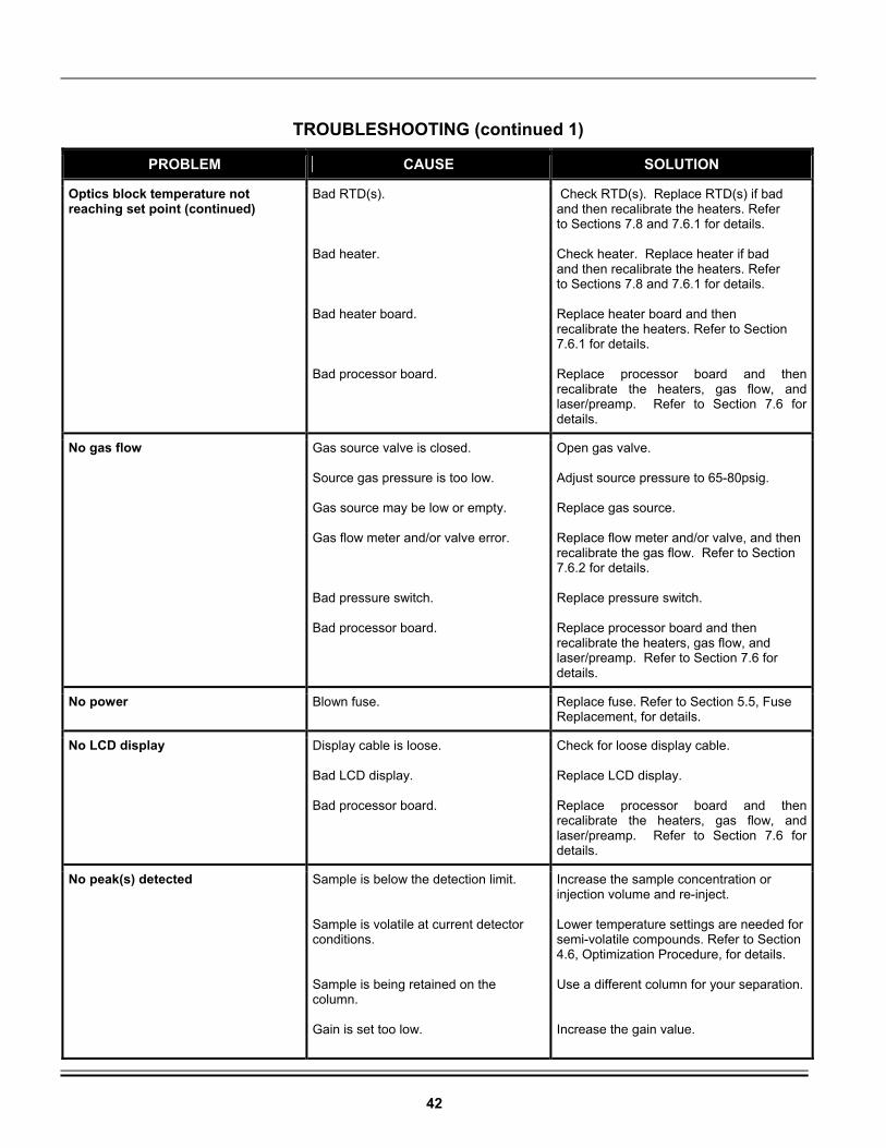
42
TROUBLESHOOTING (continued 1)
PROBLEM CAUSE SOLUTION
Optics block temperature not reaching set point (continued)
Bad RTD(s). Bad heater. Bad heater board. Bad processor board.
Check RTD(s). Replace RTD(s) if bad and then recalibrate the heaters. Refer to Sections 7.8 and 7.6.1 for details. Check heater. Replace heater if bad and then recalibrate the heaters. Refer to Sections 7.8 and 7.6.1 for details. Replace heater board and then recalibrate the heaters. Refer to Section 7.6.1 for details. Replace processor board and then recalibrate the heaters, gas flow, and laser/preamp. Refer to Section 7.6 for details.
No gas flow Gas source valve is closed. Source gas pressure is too low. Gas source may be low or empty. Gas flow meter and/or valve error. Bad pressure switch. Bad processor board.
Open gas valve. Adjust source pressure to 65-80psig. Replace gas source. Replace flow meter and/or valve, and then recalibrate the gas flow. Refer to Section 7.6.2 for details. Replace pressure switch. Replace processor board and then recalibrate the heaters, gas flow, and laser/preamp. Refer to Section 7.6 for details.
No power Blown fuse. Replace fuse. Refer to Section 5.5, Fuse Replacement, for details.
No LCD display Display cable is loose. Bad LCD display. Bad processor board.
Check for loose display cable. Replace LCD display. Replace processor board and then recalibrate the heaters, gas flow, and laser/preamp. Refer to Section 7.6 for details.
No peak(s) detected
Sample is below the detection limit. Sample is volatile at current detector conditions. Sample is being retained on the column. Gain is set too low.
Increase the sample concentration or injection volume and re-inject. Lower temperature settings are needed for semi-volatile compounds. Refer to Section 4.6, Optimization Procedure, for details. Use a different column for your separation. Increase the gain value.
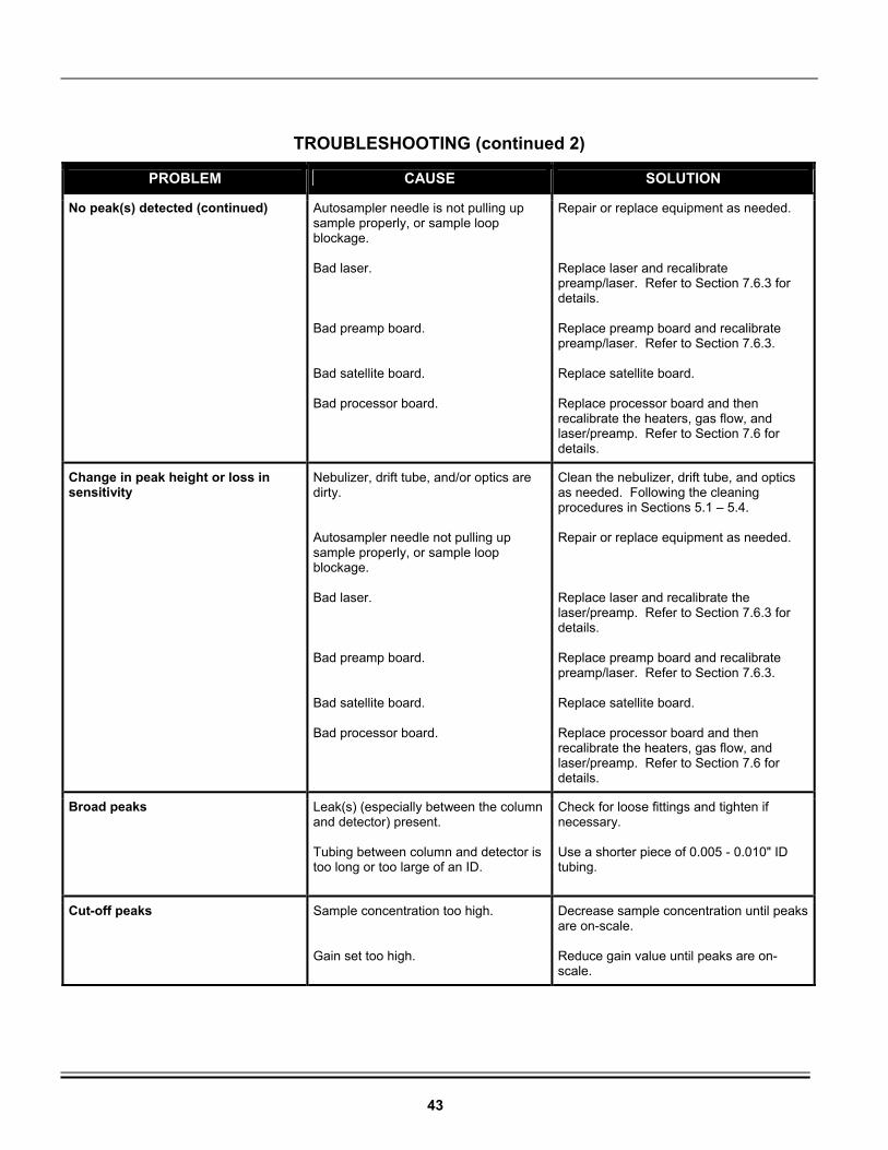
43
TROUBLESHOOTING (continued 2)
PROBLEM CAUSE SOLUTION
No peak(s) detected (continued) Autosampler needle is not pulling up sample properly, or sample loop blockage. Bad laser. Bad preamp board. Bad satellite board. Bad processor board.
Repair or replace equipment as needed. Replace laser and recalibrate preamp/laser. Refer to Section 7.6.3 for details. Replace preamp board and recalibrate preamp/laser. Refer to Section 7.6.3. Replace satellite board. Replace processor board and then recalibrate the heaters, gas flow, and laser/preamp. Refer to Section 7.6 for details.
Change in peak height or loss in sensitivity
Nebulizer, drift tube, and/or optics are dirty. Autosampler needle not pulling up sample properly, or sample loop blockage. Bad laser. Bad preamp board. Bad satellite board. Bad processor board.
Clean the nebulizer, drift tube, and optics as needed. Following the cleaning procedures in Sections 5.1 – 5.4. Repair or replace equipment as needed. Replace laser and recalibrate the laser/preamp. Refer to Section 7.6.3 for details. Replace preamp board and recalibrate preamp/laser. Refer to Section 7.6.3. Replace satellite board. Replace processor board and then recalibrate the heaters, gas flow, and laser/preamp. Refer to Section 7.6 for details.
Broad peaks Leak(s) (especially between the column and detector) present. Tubing between column and detector is too long or too large of an ID.
Check for loose fittings and tighten if necessary. Use a shorter piece of 0.005 - 0.010" ID tubing.
Cut-off peaks Sample concentration too high. Gain set too high.
Decrease sample concentration until peaks are on-scale. Reduce gain value until peaks are on-scale.
44
6.5 SOFTWARE TROUBLESHOOTING PROCEDURE
Use the following procedure to help customers troubleshoot the software on the 3300 ELSD: 1. Obtain the following information from the customer: a. A detailed description of the error, including any error messages displayed on the unit. b. Serial number of the detector. c. Software versions on the detector. The software versions on the detector can be obtained by going to Maintenance/About on the unit. d. Configuration, Error Log, and Method files exported from their unit. These files can be exported by inserting a USB pen drive (must be 128MB or less; pen drives with greater than 128MB are not compatible with the 3300 ELSD) into the USB Host port on the back panel of the unit. Then select Maintenance/Files/Export in the software to export the files. The pen drive can then be removed and the files can be sent via email to Grace/Alltech Technical Support: [email protected]. e. The information obtained from the customer will then be forwarded to the Grace/Alltech Engineering department who will provide further assistance.
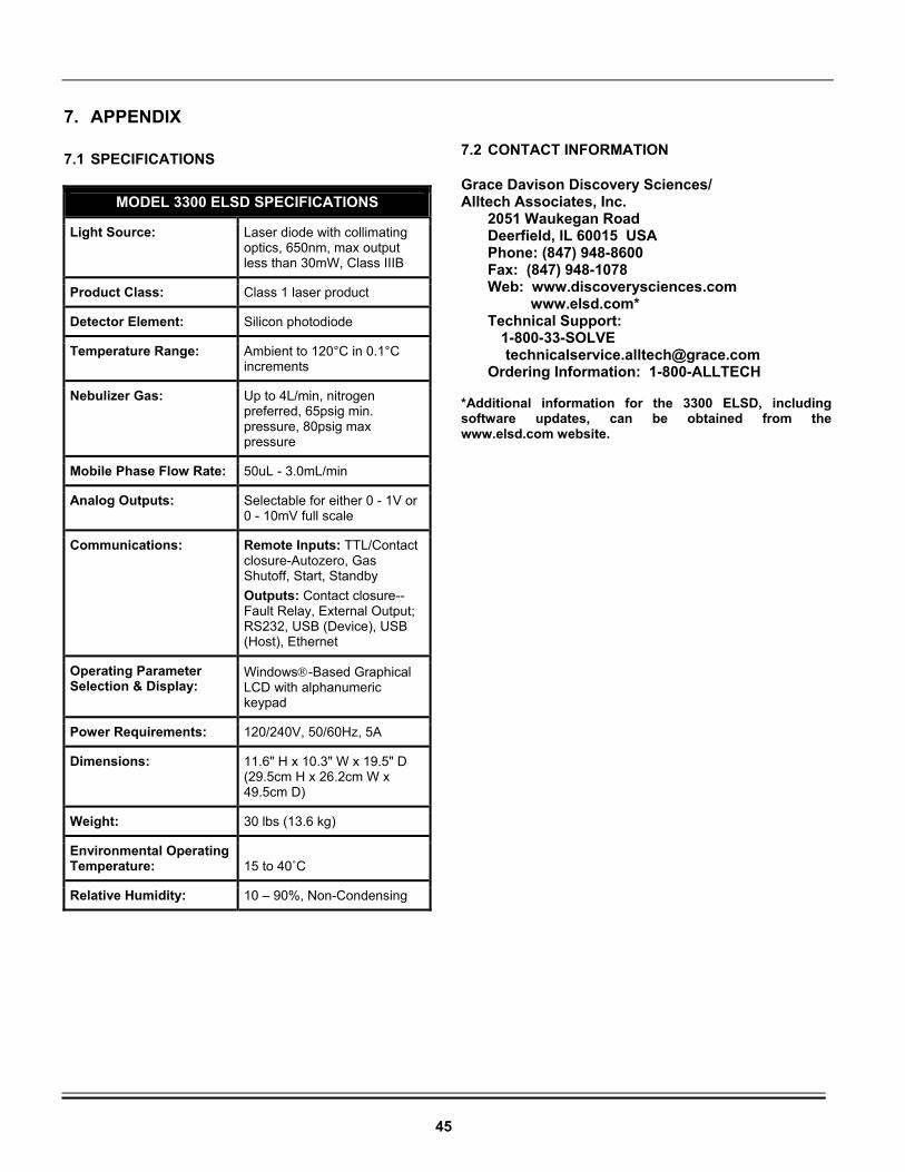
45
7. APPENDIX
7.1 SPECIFICATIONS
7.2 CONTACT INFORMATION
Grace Davison Discovery Sciences/ Alltech Associates, Inc. 2051 Waukegan Road Deerfield, IL 60015 USA Phone: (847) 948-8600 Fax: (847) 948-1078 Web: www.discoverysciences.com www.elsd.com* Technical Support: 1-800-33-SOLVE [email protected] Ordering Information: 1-800-ALLTECH *Additional information for the 3300 ELSD, including software updates, can be obtained from the www.elsd.com website.
MODEL 3300 ELSD SPECIFICATIONS
Light Source: Laser diode with collimating optics, 650nm, max output less than 30mW, Class IIIB
Product Class: Class 1 laser product
Detector Element: Silicon photodiode
Temperature Range: Ambient to 120°C in 0.1°C increments
Nebulizer Gas: Up to 4L/min, nitrogen preferred, 65psig min. pressure, 80psig max pressure
Mobile Phase Flow Rate: 50uL - 3.0mL/min
Analog Outputs: Selectable for either 0 - 1V or 0 - 10mV full scale
Communications: Remote Inputs: TTL/Contact closure-Autozero, Gas Shutoff, Start, Standby Outputs: Contact closure--Fault Relay, External Output; RS232, USB (Device), USB (Host), Ethernet
Operating Parameter Selection & Display:
Windows-Based Graphical LCD with alphanumeric keypad
Power Requirements: 120/240V, 50/60Hz, 5A
Dimensions: 11.6" H x 10.3" W x 19.5" D (29.5cm H x 26.2cm W x 49.5cm D)
Weight: 30 lbs (13.6 kg)
Environmental Operating Temperature:
15 to 40˚C
Relative Humidity: 10 – 90%, Non-Condensing
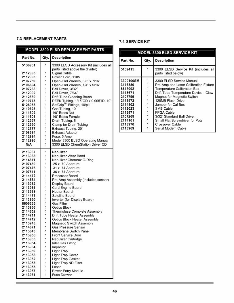
46
7.3 REPLACEMENT PARTS
MODEL 3300 ELSD REPLACEMENT PARTS
Part No. Qty. Description
5136931
2112995 2112993 2107259 2106694 2107268 2112992 2112880 2110773 5126955 2110623 2111502 2111503 2112997 2112990 3112777 2108384 2112994 2112996
N/A
1 1 1 1 1 1 1 1 1 1 1 1 1 1 1 1 1 1 1 1
3300 ELSD Accessory Kit (includes all parts listed above the divider) Signal Cable Power Cord, 110V Open-End Wrench, 3/8” x 7/16” Open-End Wrench, 1/4” x 5/16” Ball Driver, 3/32” Ball Driver, 7/64” Drift Tube Cleaning Brush PEEK Tubing, 1/16”OD x 0.005”ID, 10’SofGripTM Fittings, 10/pk Gas Tubing, 10’ 1/8” Brass Nut 1/8” Brass Ferrule Drain Tubing, 5’ Clamp for Drain Tubing Exhaust Tubing, 20’ Exhaust Adaptor Fuse, 5 Amp Model 3300 ELSD Operating Manual 3300 ELSD ChemStation Driver CD
2113967 2113968 2114811 2107480 2107476 2107511 2114472 2114584 2113962 2113961 2113963 2114471 2113960 8606365 2113966 2114652 2114711 2114712 2113943 2114671 2113643 2113956 2113965 2113954 2113964 2113959 2113958 2113952 2113953 2113955 2113957 2113951
1 1 1 1 1 1 1 1 1 1 1 1 1 1 1 1 1 1 1 1 1 1 1 1 1 1 1 1 1 1 1 1
Nebulizer Nebulizer Wear Band Nebulizer Chemraz O-Ring .25 x .79 Aperture .31 x .74 Aperture .36 x .74 Aperture Processor Board Pre-Amp Assembly (includes sensor) Display Board Card Engine Board Heater Board Satellite Board Inverter (for Display Board) Gas Filter Optics Block Thermofuse Complete Assembly Drift Tube Heater Assembly Optics Block Heater Assembly Magnetic Switch Assembly Gas Pressure Sensor Membrane Switch Panel Front Service Door Nebulizer Cartridge Inlet Gas Fitting Impactor Light Trap Light Trap Cover Light Trap Gasket Light Trap ND Filter Laser Power Entry Module Fuse Drawer
7.4 SERVICE KIT
MODEL 3300 ELSD SERVICE KIT
Part No. Qty. Description
5139415
1 3300 ELSD Service Kit (includes all parts listed below)
3300100SM 3116580 8617092 3116671 2107799 2113972 2114102 3112023 2113971 2107268 2114101 2113970 2113969
1 1 1 1 1 1 1 1 1 1 1 1 1
3300 ELSD Service Manual Pre-Amp and Laser Calibration FixtureTemperature Calibration Box Drift Tube Temperature Device - Claw Magnet for Magnetic Switch 128MB Flash Drive Jumper for Cal Box SMB Cable FPGA Cable 3/32” Standard Ball Driver Small Flat Screwdriver for Pots Crossover Cable Serial Modem Cable
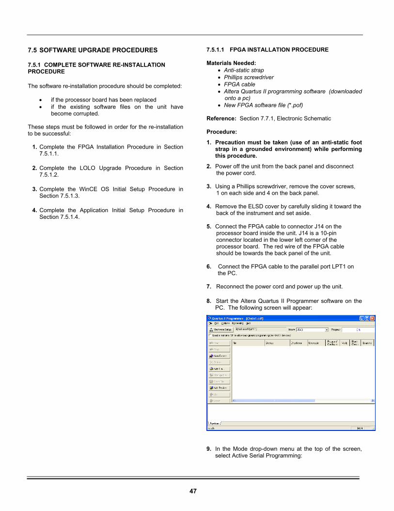
47
7.5 SOFTWARE UPGRADE PROCEDURES
7.5.1 COMPLETE SOFTWARE RE-INSTALLATION PROCEDURE
The software re-installation procedure should be completed:
• if the processor board has been replaced • if the existing software files on the unit have
become corrupted. These steps must be followed in order for the re-installation to be successful:
1. Complete the FPGA Installation Procedure in Section 7.5.1.1.
2. Complete the LOLO Upgrade Procedure in Section 7.5.1.2.
3. Complete the WinCE OS Initial Setup Procedure in Section 7.5.1.3.
4. Complete the Application Initial Setup Procedure in Section 7.5.1.4.
7.5.1.1 FPGA INSTALLATION PROCEDURE Materials Needed:
• Anti-static strap • Phillips screwdriver • FPGA cable • Altera Quartus II programming software (downloaded onto a pc) • New FPGA software file (*.pof)
Reference: Section 7.7.1, Electronic Schematic Procedure:
1. Precaution must be taken (use of an anti-static foot strap in a grounded environment) while performing this procedure.
2. Power off the unit from the back panel and disconnect the power cord. 3. Using a Phillips screwdriver, remove the cover screws, 1 on each side and 4 on the back panel. 4. Remove the ELSD cover by carefully sliding it toward the back of the instrument and set aside. 5. Connect the FPGA cable to connector J14 on the processor board inside the unit. J14 is a 10-pin connector located in the lower left corner of the processor board. The red wire of the FPGA cable should be towards the back panel of the unit. 6. Connect the FPGA cable to the parallel port LPT1 on the PC. 7. Reconnect the power cord and power up the unit.
8. Start the Altera Quartus II Programmer software on the PC. The following screen will appear:
9. In the Mode drop-down menu at the top of the screen, select Active Serial Programming:
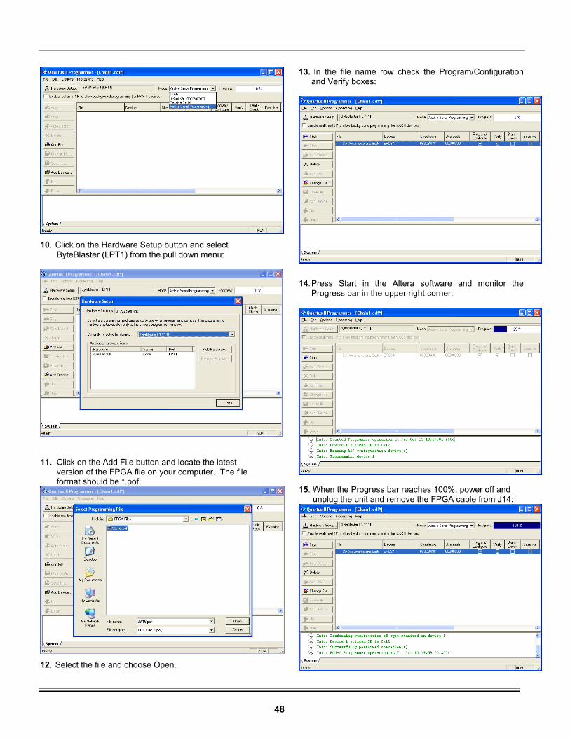
48
10. Click on the Hardware Setup button and select ByteBlaster (LPT1) from the pull down menu:
11. Click on the Add File button and locate the latest version of the FPGA file on your computer. The file format should be *.pof:
12. Select the file and choose Open.
13. In the file name row check the Program/Configuration and Verify boxes:
14. Press Start in the Altera software and monitor the Progress bar in the upper right corner:
15. When the Progress bar reaches 100%, power off and unplug the unit and remove the FPGA cable from J14:
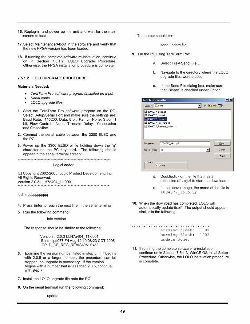
49
16. Replug in and power up the unit and wait for the main screen to load.
17. Select Maintenance/About in the software and verify that
the new FPGA version has been loaded. 18. If running the complete software re-installation, continue
on in Section 7.5.1.2, LOLO Upgrade Procedure. Otherwise, the FPGA installation procedure is complete.
7.5.1.2 LOLO UPGRADE PROCEDURE Materials Needed:
• TeraTerm Pro software program (installed on a pc) • Serial cable • LOLO upgrade files
1. Start the TeraTerm Pro software program on the PC.
Select Setup/Serial Port and make sure the settings are: Baud Rate: 115200, Data: 8 bit, Parity: None, Stop: 1 bit, Flow Control: None, Transmit Delay: 0msec/char and 0msec/line.
2. Connect the serial cable between the 3300 ELSD and the PC.
3. Power up the 3300 ELSD while holding down the “q” character on the PC keyboard. The following should appear in the serial terminal screen:
***************************************************************** LogicLoader
(c) Copyright 2002-2005, Logic Product Development, Inc. All Rights Reserved. Version 2.0.3-LLH7a404_11 0001 *****************************************************************
losh> qqqqqqqqqq
4. Press Enter to reach the next line in the serial terminal.
5. Run the following command:
info version
The response should be similar to the following: Version : 2.0.3-LLH7a404_11 0001 Build: lpd077 Fri Aug 12 10:08:23 CDT 2005 CPLD_CE_REG_REVISION: 0x32 6. Examine the version number listed in step 5. If it begins
with 2.0.5 or a larger number, the procedure can be stopped, no upgrade is necessary. If the version
begins with a number that is less than 2.0.5, continue with step 7.
7. Install the LOLO upgrade file onto the PC. 8. On the serial terminal run the following command:
update
The output should be:
send update file:
9. On the PC using TeraTerm Pro:
a. Select File->Send File…
b. Navigate to the directory where the LOLO upgrade files were placed.
c. In the Send File dialog box, make sure that ‘Binary’ is checked under Option.
d. Doubleclick on the file that has an extension of .upd to start the download.
e. In the above image, the name of the file is 1004077_lolo.up
10. When the download has completed, LOLO will automatically update itself. The output should appear similar to the following: ................................ erasing flash: 100% burning flash: 100% update done. 11. If running the complete software re-installation, continue on in Section 7.5.1.3, WinCE OS Initial Setup Procedure. Otherwise, the LOLO installation procedure is complete.
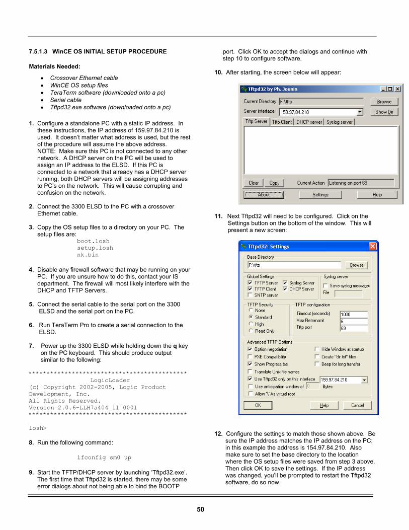
50
7.5.1.3 WinCE OS INITIAL SETUP PROCEDURE
Materials Needed:
• Crossover Ethernet cable • WinCE OS setup files • TeraTerm software (downloaded onto a pc) • Serial cable • Tftpd32.exe software (downloaded onto a pc)
1. Configure a standalone PC with a static IP address. In these instructions, the IP address of 159.97.84.210 is used. It doesn’t matter what address is used, but the rest of the procedure will assume the above address. NOTE: Make sure this PC is not connected to any other network. A DHCP server on the PC will be used to assign an IP address to the ELSD. If this PC is connected to a network that already has a DHCP server running, both DHCP servers will be assigning addresses to PC’s on the network. This will cause corrupting and confusion on the network. 2. Connect the 3300 ELSD to the PC with a crossover Ethernet cable. 3. Copy the OS setup files to a directory on your PC. The setup files are:
boot.losh setup.losh nk.bin
4. Disable any firewall software that may be running on your PC. If you are unsure how to do this, contact your IS department. The firewall will most likely interfere with the DHCP and TFTP Servers. 5. Connect the serial cable to the serial port on the 3300 ELSD and the serial port on the PC. 6. Run TeraTerm Pro to create a serial connection to the ELSD. 7. Power up the 3300 ELSD while holding down the q key on the PC keyboard. This should produce output similar to the following: ******************************************** LogicLoader (c) Copyright 2002-2005, Logic Product Development, Inc. All Rights Reserved. Version 2.0.6-LLH7a404_11 0001 ********************************************
losh>
8. Run the following command:
ifconfig sm0 up
9. Start the TFTP/DHCP server by launching ‘Tftpd32.exe’. The first time that Tftpd32 is started, there may be some error dialogs about not being able to bind the BOOTP
port. Click OK to accept the dialogs and continue with step 10 to configure software. 10. After starting, the screen below will appear:
11. Next Tftpd32 will need to be configured. Click on the Settings button on the bottom of the window. This will present a new screen:
12. Configure the settings to match those shown above. Be sure the IP address matches the IP address on the PC; in this example the address is 154.97.84.210. Also make sure to set the base directory to the location where the OS setup files were saved from step 3 above. Then click OK to save the settings. If the IP address was changed, you’ll be prompted to restart the Tftpd32 software, do so now.
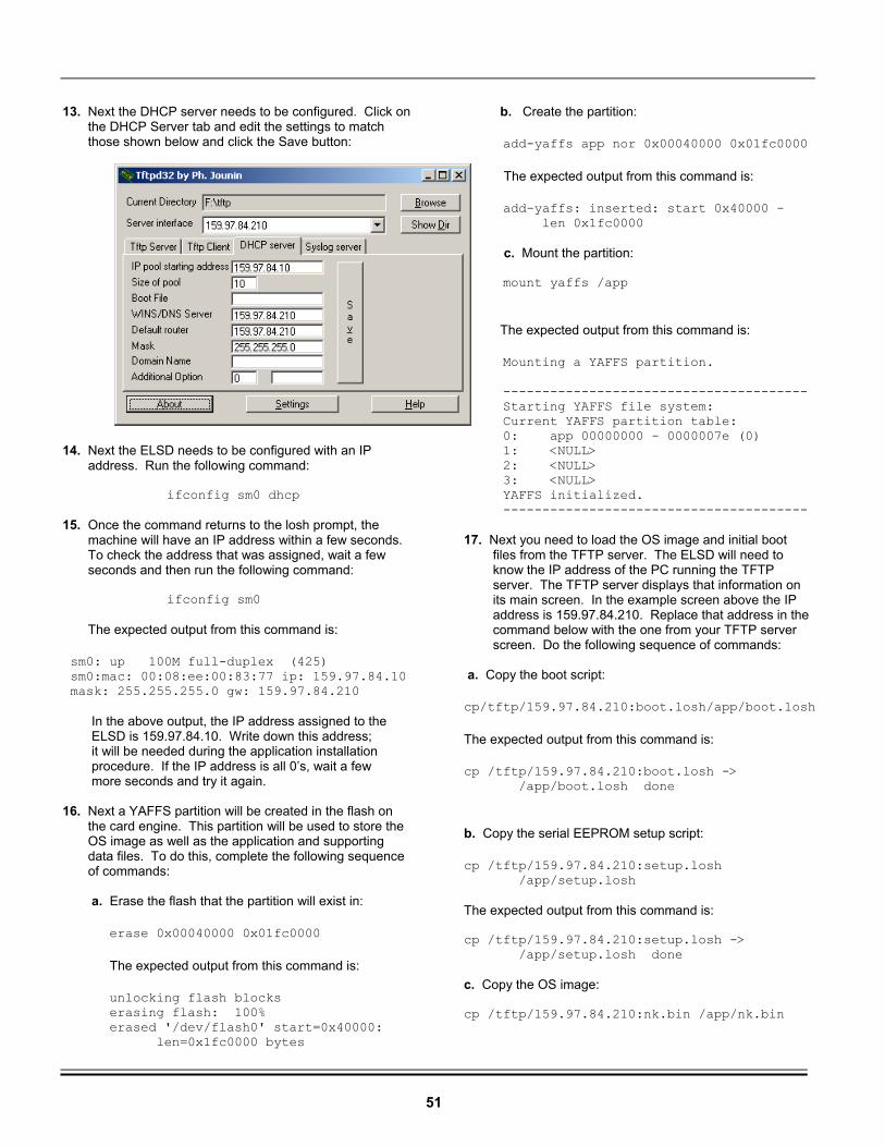
51
13. Next the DHCP server needs to be configured. Click on the DHCP Server tab and edit the settings to match those shown below and click the Save button:
14. Next the ELSD needs to be configured with an IP address. Run the following command:
ifconfig sm0 dhcp
15. Once the command returns to the losh prompt, the machine will have an IP address within a few seconds. To check the address that was assigned, wait a few seconds and then run the following command:
ifconfig sm0
The expected output from this command is:
sm0: up 100M full-duplex (425) sm0:mac: 00:08:ee:00:83:77 ip: 159.97.84.10 mask: 255.255.255.0 gw: 159.97.84.210
In the above output, the IP address assigned to the ELSD is 159.97.84.10. Write down this address; it will be needed during the application installation procedure. If the IP address is all 0’s, wait a few more seconds and try it again. 16. Next a YAFFS partition will be created in the flash on the card engine. This partition will be used to store the OS image as well as the application and supporting data files. To do this, complete the following sequence of commands: a. Erase the flash that the partition will exist in:
erase 0x00040000 0x01fc0000
The expected output from this command is:
unlocking flash blocks erasing flash: 100% erased '/dev/flash0' start=0x40000: len=0x1fc0000 bytes
b. Create the partition:
add-yaffs app nor 0x00040000 0x01fc0000
The expected output from this command is:
add-yaffs: inserted: start 0x40000 - len 0x1fc0000 c. Mount the partition: mount yaffs /app
The expected output from this command is:
Mounting a YAFFS partition.
--------------------------------------- Starting YAFFS file system: Current YAFFS partition table: 0: app 00000000 - 0000007e (0) 1: <NULL> 2: <NULL> 3: <NULL> YAFFS initialized. --------------------------------------- 17. Next you need to load the OS image and initial boot files from the TFTP server. The ELSD will need to know the IP address of the PC running the TFTP server. The TFTP server displays that information on its main screen. In the example screen above the IP address is 159.97.84.210. Replace that address in the command below with the one from your TFTP server screen. Do the following sequence of commands: a. Copy the boot script:
cp/tftp/159.97.84.210:boot.losh/app/boot.losh
The expected output from this command is:
cp /tftp/159.97.84.210:boot.losh -> /app/boot.losh done
b. Copy the serial EEPROM setup script:
cp /tftp/159.97.84.210:setup.losh /app/setup.losh The expected output from this command is: cp /tftp/159.97.84.210:setup.losh -> /app/setup.losh done c. Copy the OS image: cp /tftp/159.97.84.210:nk.bin /app/nk.bin
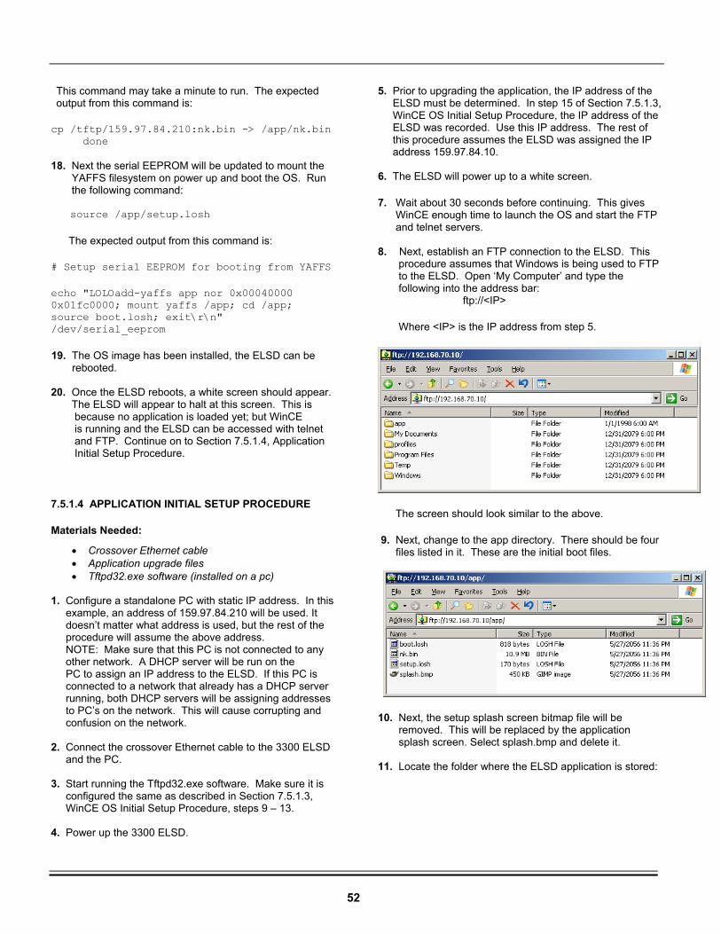
52
This command may take a minute to run. The expected output from this command is:
cp /tftp/159.97.84.210:nk.bin -> /app/nk.bin done 18. Next the serial EEPROM will be updated to mount the YAFFS filesystem on power up and boot the OS. Run the following command: source /app/setup.losh
The expected output from this command is:
# Setup serial EEPROM for booting from YAFFS
echo "LOLOadd-yaffs app nor 0x00040000 0x01fc0000; mount yaffs /app; cd /app; source boot.losh; exit\r\n" /dev/serial_eeprom
19. The OS image has been installed, the ELSD can be rebooted. 20. Once the ELSD reboots, a white screen should appear. The ELSD will appear to halt at this screen. This is because no application is loaded yet; but WinCE is running and the ELSD can be accessed with telnet and FTP. Continue on to Section 7.5.1.4, Application Initial Setup Procedure.
7.5.1.4 APPLICATION INITIAL SETUP PROCEDURE
Materials Needed:
• Crossover Ethernet cable • Application upgrade files • Tftpd32.exe software (installed on a pc)
1. Configure a standalone PC with static IP address. In this example, an address of 159.97.84.210 will be used. It doesn’t matter what address is used, but the rest of the procedure will assume the above address. NOTE: Make sure that this PC is not connected to any other network. A DHCP server will be run on the PC to assign an IP address to the ELSD. If this PC is connected to a network that already has a DHCP server running, both DHCP servers will be assigning addresses to PC’s on the network. This will cause corrupting and confusion on the network. 2. Connect the crossover Ethernet cable to the 3300 ELSD and the PC. 3. Start running the Tftpd32.exe software. Make sure it is configured the same as described in Section 7.5.1.3, WinCE OS Initial Setup Procedure, steps 9 – 13. 4. Power up the 3300 ELSD.
5. Prior to upgrading the application, the IP address of the ELSD must be determined. In step 15 of Section 7.5.1.3, WinCE OS Initial Setup Procedure, the IP address of the ELSD was recorded. Use this IP address. The rest of this procedure assumes the ELSD was assigned the IP address 159.97.84.10. 6. The ELSD will power up to a white screen.
7. Wait about 30 seconds before continuing. This gives WinCE enough time to launch the OS and start the FTP and telnet servers. 8. Next, establish an FTP connection to the ELSD. This procedure assumes that Windows is being used to FTP to the ELSD. Open ‘My Computer’ and type the following into the address bar:
ftp://<IP>
Where <IP> is the IP address from step 5.
The screen should look similar to the above.
9. Next, change to the app directory. There should be four files listed in it. These are the initial boot files.
10. Next, the setup splash screen bitmap file will be removed. This will be replaced by the application splash screen. Select splash.bmp and delete it. 11. Locate the folder where the ELSD application is stored:
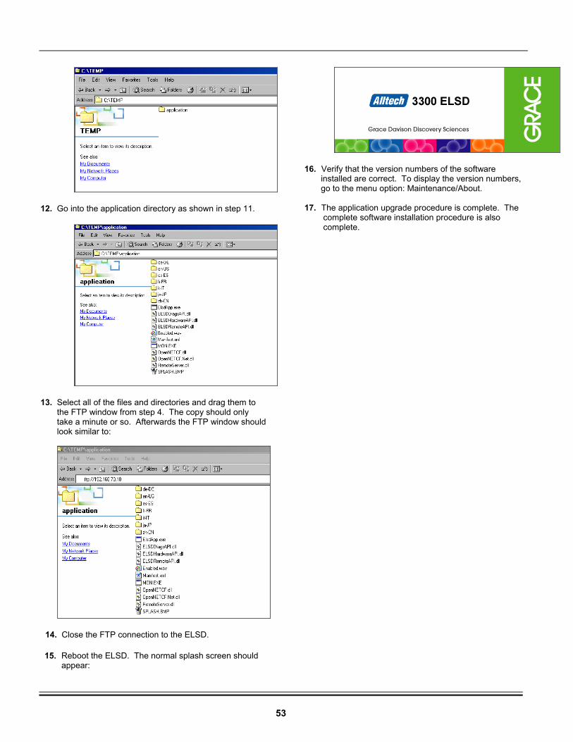
53
12. Go into the application directory as shown in step 11.
13. Select all of the files and directories and drag them to the FTP window from step 4. The copy should only take a minute or so. Afterwards the FTP window should look similar to:
14. Close the FTP connection to the ELSD.
15. Reboot the ELSD. The normal splash screen should appear:
16. Verify that the version numbers of the software installed are correct. To display the version numbers, go to the menu option: Maintenance/About. 17. The application upgrade procedure is complete. The complete software installation procedure is also complete.
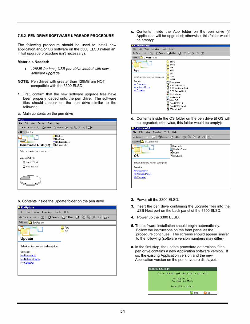
54
7.5.2 PEN DRIVE SOFTWARE UPGRADE PROCEDURE
The following procedure should be used to install new application and/or OS software on the 3300 ELSD (when an initial upgrade procedure isn’t necessary). Materials Needed:
• 128MB (or less) USB pen drive loaded with new software upgrade
NOTE: Pen drives with greater than 128MB are NOT compatible with the 3300 ELSD. 1. First, confirm that the new software upgrade files have
been properly loaded onto the pen drive. The software files should appear on the pen drive similar to the following:
a. Main contents on the pen drive
b. Contents inside the Update folder on the pen drive
c. Contents inside the App folder on the pen drive (if Application will be upgraded; otherwise, this folder would be empty):
d. Contents inside the OS folder on the pen drive (if OS will
be upgraded; otherwise, this folder would be empty):
2. Power off the 3300 ELSD.
3. Insert the pen drive containing the upgrade files into the USB Host port on the back panel of the 3300 ELSD.
4. Power up the 3300 ELSD. 5. The software installation should begin automatically. Follow the instructions on the front panel as the procedure continues. The screens should appear similar to the following (software version numbers may differ): a. In the first step, the update procedure determines if the pen drive contains a new Application software version. If so, the existing Application version and the new Application version on the pen drive are displayed:
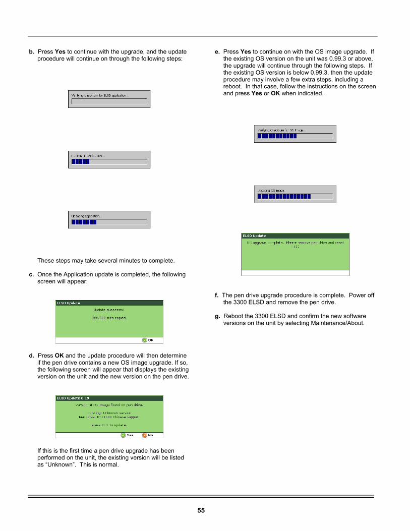
55
b. Press Yes to continue with the upgrade, and the update procedure will continue on through the following steps:
These steps may take several minutes to complete. c. Once the Application update is completed, the following screen will appear:
d. Press OK and the update procedure will then determine if the pen drive contains a new OS image upgrade. If so, the following screen will appear that displays the existing version on the unit and the new version on the pen drive.
If this is the first time a pen drive upgrade has been performed on the unit, the existing version will be listed as “Unknown”. This is normal.
e. Press Yes to continue on with the OS image upgrade. If the existing OS version on the unit was 0.99.3 or above, the upgrade will continue through the following steps. If the existing OS version is below 0.99.3, then the update procedure may involve a few extra steps, including a reboot. In that case, follow the instructions on the screen and press Yes or OK when indicated.
f. The pen drive upgrade procedure is complete. Power off the 3300 ELSD and remove the pen drive. g. Reboot the 3300 ELSD and confirm the new software versions on the unit by selecting Maintenance/About.
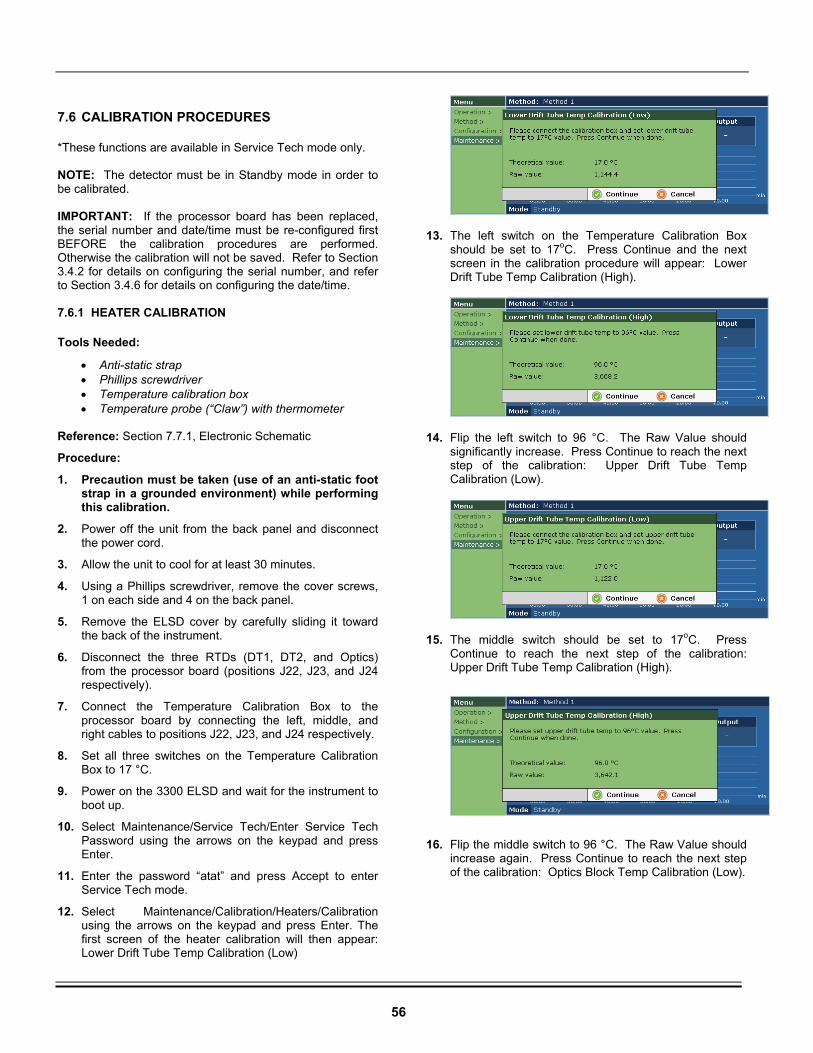
56
7.6 CALIBRATION PROCEDURES
*These functions are available in Service Tech mode only. NOTE: The detector must be in Standby mode in order to be calibrated. IMPORTANT: If the processor board has been replaced, the serial number and date/time must be re-configured first BEFORE the calibration procedures are performed. Otherwise the calibration will not be saved. Refer to Section 3.4.2 for details on configuring the serial number, and refer to Section 3.4.6 for details on configuring the date/time. 7.6.1 HEATER CALIBRATION
Tools Needed:
• Anti-static strap • Phillips screwdriver • Temperature calibration box • Temperature probe (“Claw”) with thermometer
Reference: Section 7.7.1, Electronic Schematic
Procedure:
1. Precaution must be taken (use of an anti-static foot strap in a grounded environment) while performing this calibration.
2. Power off the unit from the back panel and disconnect the power cord.
3. Allow the unit to cool for at least 30 minutes.
4. Using a Phillips screwdriver, remove the cover screws, 1 on each side and 4 on the back panel.
5. Remove the ELSD cover by carefully sliding it toward the back of the instrument.
6. Disconnect the three RTDs (DT1, DT2, and Optics) from the processor board (positions J22, J23, and J24 respectively).
7. Connect the Temperature Calibration Box to the processor board by connecting the left, middle, and right cables to positions J22, J23, and J24 respectively.
8. Set all three switches on the Temperature Calibration Box to 17 °C.
9. Power on the 3300 ELSD and wait for the instrument to boot up.
10. Select Maintenance/Service Tech/Enter Service Tech Password using the arrows on the keypad and press Enter.
11. Enter the password “atat” and press Accept to enter Service Tech mode.
12. Select Maintenance/Calibration/Heaters/Calibration using the arrows on the keypad and press Enter. The first screen of the heater calibration will then appear: Lower Drift Tube Temp Calibration (Low)
13. The left switch on the Temperature Calibration Box
should be set to 17oC. Press Continue and the next screen in the calibration procedure will appear: Lower Drift Tube Temp Calibration (High).
14. Flip the left switch to 96 °C. The Raw Value should
significantly increase. Press Continue to reach the next step of the calibration: Upper Drift Tube Temp Calibration (Low).
15. The middle switch should be set to 17oC. Press
Continue to reach the next step of the calibration: Upper Drift Tube Temp Calibration (High).
16. Flip the middle switch to 96 °C. The Raw Value should
increase again. Press Continue to reach the next step of the calibration: Optics Block Temp Calibration (Low).
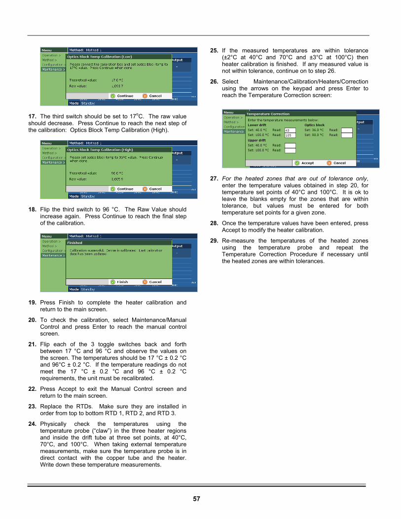
57
17. The third switch should be set to 17oC. The raw value should decrease. Press Continue to reach the next step of the calibration: Optics Block Temp Calibration (High).
18. Flip the third switch to 96 °C. The Raw Value should
increase again. Press Continue to reach the final step of the calibration.
19. Press Finish to complete the heater calibration and
return to the main screen.
20. To check the calibration, select Maintenance/Manual Control and press Enter to reach the manual control screen.
21. Flip each of the 3 toggle switches back and forth between 17 °C and 96 °C and observe the values on the screen. The temperatures should be 17 °C ± 0.2 °C and 96°C ± 0.2 °C. If the temperature readings do not meet the 17 °C ± 0.2 °C and 96 °C ± 0.2 °C requirements, the unit must be recalibrated.
22. Press Accept to exit the Manual Control screen and return to the main screen.
23. Replace the RTDs. Make sure they are installed in order from top to bottom RTD 1, RTD 2, and RTD 3.
24. Physically check the temperatures using the temperature probe (“claw”) in the three heater regions and inside the drift tube at three set points, at 40°C, 70°C, and 100°C. When taking external temperature measurements, make sure the temperature probe is in direct contact with the copper tube and the heater. Write down these temperature measurements.
25. If the measured temperatures are within tolerance (±2°C at 40°C and 70°C and ±3°C at 100°C) then heater calibration is finished. If any measured value is not within tolerance, continue on to step 26.
26. Select Maintenance/Calibration/Heaters/Correction using the arrows on the keypad and press Enter to reach the Temperature Correction screen:
27. For the heated zones that are out of tolerance only,
enter the temperature values obtained in step 20, for temperature set points of 40°C and 100°C. It is ok to leave the blanks empty for the zones that are within tolerance, but values must be entered for both temperature set points for a given zone.
28. Once the temperature values have been entered, press Accept to modify the heater calibration.
29. Re-measure the temperatures of the heated zones using the temperature probe and repeat the Temperature Correction Procedure if necessary until the heated zones are within tolerances.
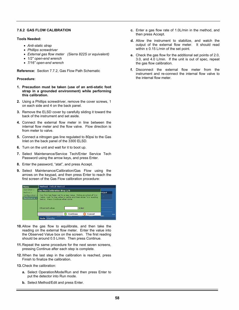
58
7.6.2 GAS FLOW CALIBRATION
Tools Needed:
• Anti-static strap • Phillips screwdriver • External gas flow meter (Sierra 822S or equivalent) • 1/2” open-end wrench • 7/16” open-end wrench
Reference: Section 7.7.2, Gas Flow Path Schematic Procedure: 1. Precaution must be taken (use of an anti-static foot
strap in a grounded environment) while performing this calibration.
2. Using a Phillips screwdriver, remove the cover screws, 1 on each side and 4 on the back panel.
3. Remove the ELSD cover by carefully sliding it toward the back of the instrument and set aside.
4. Connect the external flow meter in line between the internal flow meter and the flow valve. Flow direction is from meter to valve.
5. Connect a nitrogen gas line regulated to 80psi to the Gas Inlet on the back panel of the 3300 ELSD.
6. Turn on the unit and wait for it to boot up.
7. Select Maintenance/Service Tech/Enter Service Tech Password using the arrow keys, and press Enter.
8. Enter the password, “atat”, and press Accept.
9. Select Maintenance/Calibration/Gas Flow using the arrows on the keypad, and then press Enter to reach the first screen of the Gas Flow calibration procedure:
10. Allow the gas flow to equilibrate, and then take the reading on the external flow meter. Enter the value into the Observed Value box on the screen. The first reading should be around 0.5 L/min. Then press Continue.
11. Repeat the same procedure for the next seven screens, pressing Continue after each step is complete.
12. When the last step in the calibration is reached, press Finish to finalize the calibration.
13. Check the calibration:
a. Select Operation/Mode/Run and then press Enter to put the detector into Run mode.
b. Select Method/Edit and press Enter.
c. Enter a gas flow rate of 1.0L/min in the method, and then press Accept.
d. Allow the instrument to stabilize, and watch the output of the external flow meter. It should read within ± 0.15 L/min of the set point.
e. Check the gas flow for the additional set points of 2.0, 3.0, and 4.0 L/min. If the unit is out of spec, repeat the gas flow calibration.
f. Disconnect the external flow meter from the instrument and re-connect the internal flow valve to the internal flow meter.
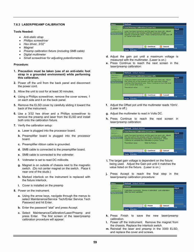
59
7.6.3 LASER/PREAMP CALIBRATION
Tools Needed:
• Anti-static strap • Phillips screwdriver • Hex driver, 3/32” • Magnet • Preamp calibration fixture (including SMB cable) • Digital multimeter • Small screwdriver for adjusting potentiometers
Procedure: 1. Precaution must be taken (use of an anti-static foot
strap in a grounded environment) while performing this calibration.
2. Power off the unit from the back panel and disconnect the power cord.
3. Allow the unit to cool for at least 30 minutes.
4. Using a Phillips screwdriver, remove the cover screws, 1 on each side and 4 on the back panel.
5. Remove the ELSD cover by carefully sliding it toward the back of the instrument.
6. Use a 3/32 hex driver and a Phillips screwdriver to remove the preamp and laser from the ELSD and install both onto the calibration fixture.
7. Verify the calibration setup:
a. Laser is plugged into the processor board.
b. Preamplifier board is plugged into the processor board.
c. Preamplifier ribbon cable is grounded.
d. SMB cable is connected to the preamplifier board.
e. SMB cable is connected to the voltmeter.
f. Voltmeter is set to read DC millivolts.
g. Magnet is on outside of chassis next to the magnetic switch. (Do not center magnet on the switch. Place it near one of the studs.)
h. Marked interlock on the instrument is replaced with the fixture interlock.
i. Cover is installed on the preamp
8. Power on the instrument.
a. Using the arrow keys, navigate through the menus to select Maintenance/Service Tech/Enter Service Tech Password and hit Enter.
b. Enter the password “atat” and press Accept.
c. Select Maintenance/Calibration/Laser/Preamp and press Enter. The first screen of the laser/preamp calibration procedure will appear:
d. Adjust the gain pot until a maximum voltage is measured with the multimeter. (Laser is on.)
e. Press Continue to reach the next screen in the laser/preamp calibration:
f. Adjust the Offset pot until the multimeter reads 10mV. (Laser is off.)
g. Adjust the multimeter to read in Volts DC.
h. Press Continue to reach the next screen in laser/preamp calibration:
i. The target gain voltage is dependent on the fixture being used. Adjust the Gain pot until it matches the value listed on the fixture. (Laser is on.)
j. Press Accept to reach the final step in the laser/preamp calibration procedure:
k. Press Finish to save the new laser/preamp calibration.
l. Power off the instrument. Remove the magnet from the chassis. Replace the interlock switch.
m. Reinstall the laser and preamp in the 3300 ELSD, and replace the cover and screws.
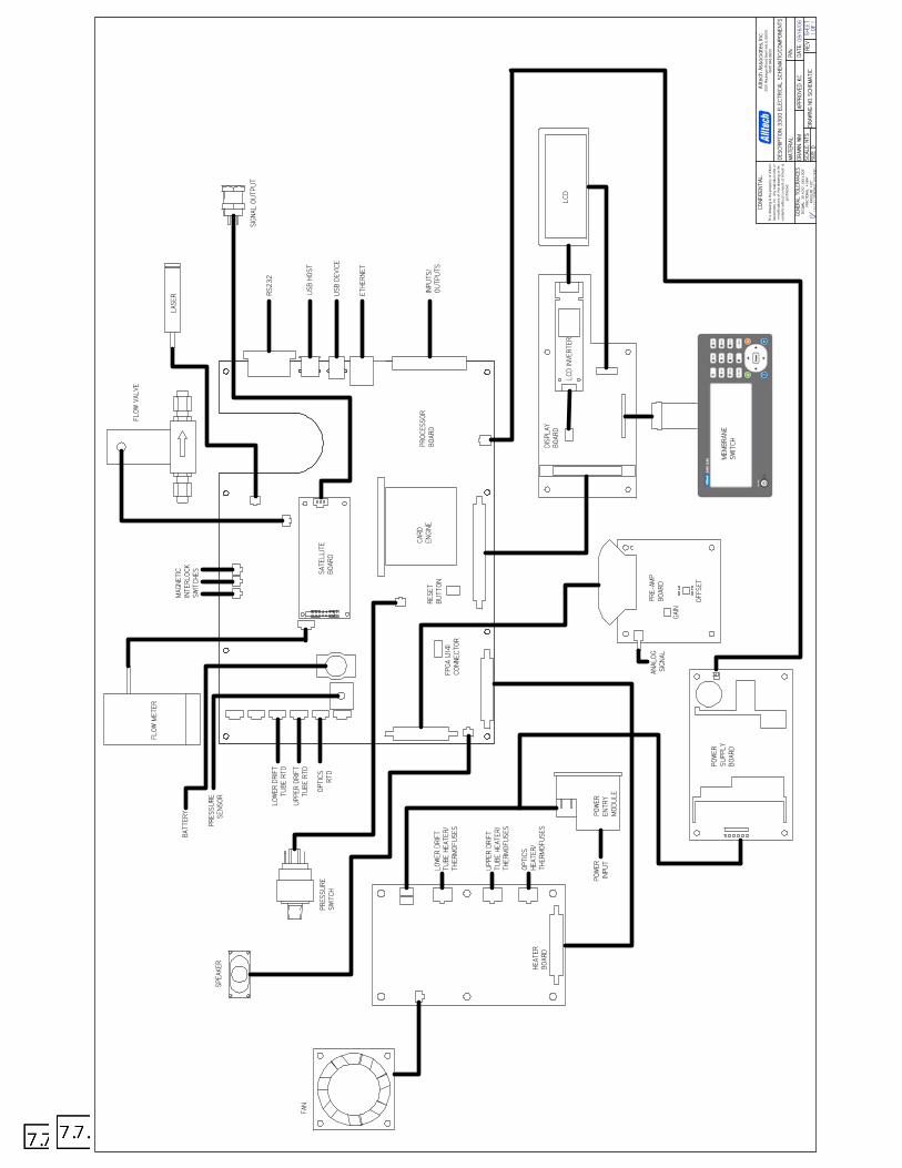
08/1
6/06
DESC
RIPT
ION:
330
0 EL
ECTR
ICAL
SCH
EMAT
IC/C
OMPO
NENT
S
DATE
:AP
PROV
ED: K
CDR
AWN:
WM
CONF
IDEN
TIAL
:
This
dra
win
g is
the
prop
erty
of
Allte
chAs
soci
ates
, Inc
. An
y re
prod
uctio
ns o
rm
odifi
catio
ns o
f thi
s dr
awin
g or
its
cont
ents
with
out c
onse
nt o
f Al
ltech
ispr
ohib
ited.
Allte
ch A
ssoc
iate
s, In
c.20
51 W
auke
gan
Road
, Dee
rfie
ld, IL
600
15(8
47) 9
48-8
600
MAT
ERIA
L:
DRAW
ING
NO: S
CHEM
ATIC
REV
SHEE
T1
OF 1
SCAL
E: N
TSSI
ZE D
P/N:
GENE
RAL
TOLE
RANC
ES D
ECIM
AL:
.XX
±.010
"; .X
XX ±
.005
"FR
ACTI
ONAL
: ±
1/64
"AN
GULA
R: ±
1/2º
63U
NLES
S OT
HERW
ISE
SPEC
IFIE
D
PROC
ESSO
RBO
ARD
FLOW
VAL
VE
LASE
R
SATE
LLIT
EBO
ARD
CARD
ENGI
NE
PRE-
AMP
BOAR
D
FLOW
MET
ER
FAN
PRES
SURE
SWIT
CH
LCD
HEAT
ERBO
ARD
POW
EREN
TRY
MOD
ULE
POW
ERSU
PPLY
BOAR
DM
EMBR
ANE
SWIT
CHDISP
LAY
BOAR
D
LCD
INVE
RTER
OPTI
CS RTD
UPP
ER D
RIFT
TUBE
RTD
LOW
ER D
RIFT
TUBE
RTD
OPTI
CSHE
ATER
/TH
ERM
OFU
SES
LOW
ER D
RIFT
TUBE
HEA
TER/
THER
MOF
USE
S
UPP
ER D
RIFT
TUBE
HEA
TER/
THER
MOF
USE
S
MAG
NETI
CIN
TERL
OCK
SWIT
CHES
PRES
SURE
SENS
OR
BATT
ERY
SPEA
KER
FPGA
(J14
)CO
NNEC
TOR
RESE
TBU
TTON
RS23
2
USB
HO
ST
USB
DEV
ICE
ETHE
RNET
INPU
TS/
OUTP
UTS
SIGN
AL O
UTP
UT
POW
ERIN
PUT
ANAL
OGSI
GNAL
GAIN
OFFS
ET
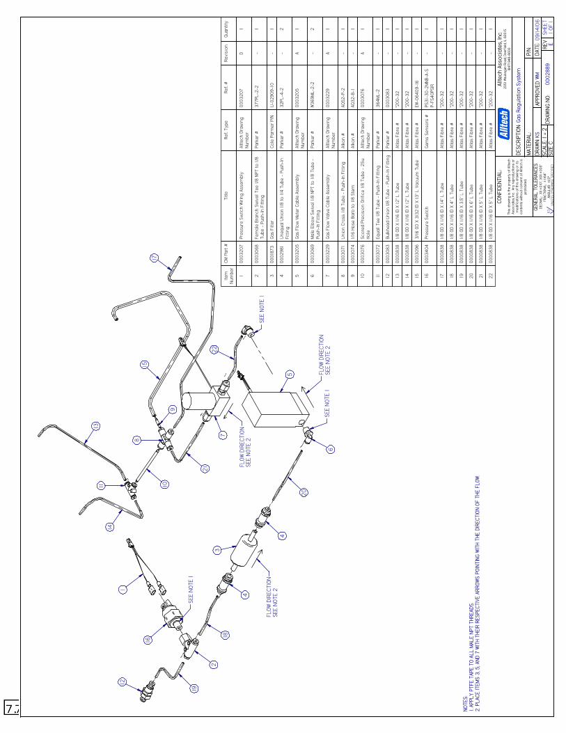
NOTE
S:1.
APPL
Y PT
FE T
APE
TO A
LL M
ALE
NPT
THRE
ADS.
2. P
LACE
ITEM
S 3,
5, A
ND 7
WIT
H TH
EIR
RESP
ECTI
VE A
RROW
S PO
INTI
NG W
ITH
THE
DIRE
CTIO
N OF
THE
FLO
W.
09/1
4/06
Gas
Regu
latio
n Sy
stem
0002
889
E
DESC
RIPT
ION:
DATE
:AP
PROV
ED:
DRAW
N:
CONF
IDEN
TIAL
:
This
dra
win
g is
the
prop
erty
of
Allte
chAs
soci
ates
, Inc.
Any
rep
rodu
ctio
ns o
rm
odifi
catio
ns o
f th
is d
raw
ing
or it
sco
nten
ts w
ithou
t con
sent
of
Allte
ch is
proh
ibite
d.
Allte
ch A
ssoc
iate
s, In
c.20
51 W
auke
gan
Road
, Dee
rfie
ld, IL
600
15(8
47) 9
48-8
600
MAT
ERIA
L:
DRAW
ING
NO:
REV
WMSH
EET
1 OF
1SC
ALE:
1 =
2SI
ZE C
P/N:
KSGE
NERA
L TO
LERA
NCES
DEC
IMAL
: .X
X ±.0
10";
.XXX
±.0
05"
FRAC
TION
AL:
± 1/
64"
ANGU
LAR:
±1/2
º63
UNL
ESS
OTHE
RWIS
E SP
ECIF
IED
Item
Num
ber
CM P
art
#Ti
tleRe
f. Ty
peRe
f. #
Revi
sion
Quan
tity
100
0320
7Pr
essu
re S
witc
h W
iring
Ass
embl
yAl
ltech
Dra
win
gNu
mbe
r00
0320
7D
1
200
0306
8Fe
mal
e Br
anch
Sw
ivel
Tee
1/8
NPT
to 1
/8Tu
be -
Pus
h-In
Fitt
ing
Park
er #
377P
L-2-
2-
1
300
0187
3Ga
s Fi
lter
Cole
Par
mer
P/N
U-0
2909
-10
-1
400
0298
1U
nequ
al U
nion
1/8
to 1
/4 T
ube
- Pu
sh-I
nFi
ttin
gPa
rker
#32
PL-4
-2-
2
500
0320
5Ga
s Fl
ow M
eter
Cab
le A
ssem
bly
Allte
ch D
raw
ing
Num
ber
0003
205
A1
600
0306
9M
ale
Elbo
w S
wiv
el 1
/8 N
PT to
1/8
Tub
e -
Push
-In
Fitt
ing
Park
er #
W36
9ML-
2-2
-2
700
0322
9Ga
s Fl
ow V
alve
Cab
le A
ssem
bly
Allte
ch D
raw
ing
Num
ber
0003
229
A1
800
0307
1U
nion
Cro
ss 1
/8 T
ube
- Pu
sh-I
n Fi
ttin
gAl
kon
#AQ
52-P
-2-
1
900
0307
41/
16 H
ose
Barb
to 1
/8 S
tem
Alko
n #
AQ32
-B-1
-1
1000
0307
6Sc
ored
Pre
cisi
on O
rific
e 1/
8 Tu
be -
25u
Hole
Allte
ch D
raw
ing
Num
ber
0003
076
A1
1100
0307
2Eq
uall
Tee
1/8
Tube
- P
ush-
In F
ittin
gPa
rker
#36
4ML-
2-
1
1200
0308
3Bu
lkhe
ad U
nion
1/8
Tub
e -
Push
-In
Fitt
ing
Park
er #
0003
083
-1
1300
0083
81/
8 OD
X 1
/16
ID X
12"
L T
ube
Atla
s Fi
bre
#*2
00-3
2-
1
1400
0083
81/
8 OD
X 1
/16
ID X
12"
L T
ube
Atla
s Fi
bre
#*2
00-3
2-
1
1500
0309
63/
16 O
D X
3/32
ID X
13"
L V
acuu
m T
ube
Atla
s Fi
bre
#EW
-064
09-1
6-
1
1600
0340
4Pr
essu
re S
witc
hGe
ms
Sens
ors
#PS
31-3
0-2M
NB-A
-SP-
FS40
PSIR
-1
1700
0083
81/
8 OD
X 1
/16
ID X
14"
L T
ube
Atla
s Fi
bre
#*2
00-3
2-
1
1800
0083
81/
8 OD
X 1
/16
ID X
4" L
Tub
eAt
las
Fibr
e #
*200
-32
-1
1900
0083
81/
8 OD
X 1
/16
ID X
3.5
" L T
ube
Atla
s Fi
bre
#*2
00-3
2-
1
2000
0083
81/
8 OD
X 1
/16
ID X
6" L
Tub
eAt
las
Fibr
e #
*200
-32
-1
2100
0083
81/
8 OD
X 1
/16
ID X
5" L
Tub
eAt
las
Fibr
e #
*200
-32
-1
2200
0083
81/
8 OD
X 1
/16
ID X
5" L
Tub
eAt
las
Fibr
e #
*200
-32
-1
12
19
2
18
4
4
17
158
101113
14
16
1
9
20
22
21
6
3
FLOW
DIR
ECTI
ONSE
E NO
TE 2
FLOW
DIR
ECTI
ONSE
E NO
TE 2
FLOW
DIR
ECTI
ONSE
E NO
TE 2
7
5
SEE
NOTE
1
SEE
NOTE
1
SEE
NOTE
1
62
7.8 HEATERS, RTDS, AND THERMOFUSES
7.8.1 CHECKING THE THERMOFUSES, RTDS, AND HEATERS
7.8.1.1 CHECKING THE THERMOFUSES
Tools Needed:
• Anti-static strap • Phillips screwdriver • Digital multimeter
Reference: Section 7.7.1, Electronic Schematic
1. Precaution must be taken (use of an anti-static foot strap in a grounded environment) while performing this procedure.
2. Power off the unit from the back panel and disconnect the power cord.
3. Before checking the thermofuses, first allow the resettable fuses 2 hours to reset.
4. Using a Phillips screwdriver, remove the cover screws, 1 on each side and 4 on the back panel.
5. Remove the ELSD cover by carefully sliding it toward the back of the instrument and set aside.
6. Locate the connector(s) on the heater board for the zones to be checked. The connectors are located at positions J4, J5, and J6, which correspond to lower drift tube, upper drift tube, and optics block, respectively. Refer to Section 7.7.1, Electronic Schematic for details.
7. Disconnect the connector(s) from the Heater Board.
8. Using a multimeter, measure the resistance between the thermofuse wires. The thermofuse wires are located on the top row of each connector. If there is infinite resistance between the wires, the thermofuse needs replacement. Refer to Section 7.8.2.3, Thermofuse Replacement Procedure, for details on replacing the thermofuse(s). If the thermofuse(s) are ok, then replace the connector(s) back to their original position(s), and replace the 3300 ELSD cover and screws.
7.8.1.2 CHECKING THE RTDS Tools Needed:
• Anti-static strap • Phillips screwdriver • Digital multimeter
Reference: Section 7.7.1, Electronic Schematic 1. Precaution must be taken (use of an anti-static foot strap in a grounded environment) while performing this procedure. 2. Power off the unit from the back panel and disconnect the power cord. 3. Before checking the thermofuses, first allow the resettable fuses 2 hours to reset. 4. Using a Phillips screwdriver, remove the cover screws, 1 on each side and 4 on the back panel. 5. Remove the ELSD cover by carefully sliding it toward the back of the instrument and set aside.
6. Locate the connector(s) for the zones to be checked. The connectors are located on the left side of the processor board at positions J22, J23, and J24, which correspond to lower drift tube, upper drift tube, and optics block, respectively. Refer to Section 7.7.1, Electronic Schematic for details.
7. Disconnect the connector(s) from the Processor Board. 8. Using a multimeter, measure the resistance between the wires. If there is infinite resistance, then the RTD needs replacement. Refer to Section 7.8.2 for details on replacing the RTD(s). If the RTD(s) are ok, then replace the connectors back to their original positions, and replace the 3300 ELSD cover and screws.
63
7.8.1.3 CHECKING THE HEATERS Tools Needed:
• Anti-static strap • Phillips screwdriver • Digital multimeter
Reference: Section 7.7.1, Electronic Schematic 1. Precaution must be taken (use of an anti-static foot strap in a grounded environment) while performing this procedure. 2. Power off the unit from the back panel and disconnect the power cord. 3. Allow the unit to cool for at least 30 minutes. 4. Using a Phillips screwdriver, remove the cover screws, 1 on each side and 4 on the back panel. 5. Remove the ELSD cover by carefully sliding it toward the back of the instrument and set aside. 6. Locate the connector(s) on the heater board for the zones to be checked. The connectors are located at positions J4, J5, and J6, which correspond to lower drift tube, upper drift tube, and optics block, respectively. Refer to Section 7.7.1, Electronic Schematic for details. 7. Disconnect the connector(s) from the Heater Board.
8. Using a multimeter, measure the resistance between the heater wires. The heater wires are located on the bottom two rows of the connector. If there is infinite resistance between the pair of wires in a row, then the heater needs replacement. Refer to Section 7.8.2.1, Heater Replacement Procedure, for details on replacing the heater(s). If the heater(s) are ok, then replace the connector(s) back to their original position(s), and replace the 3300 ELSD cover and screws.
7.8.2 HEATER, RTD, AND THERMOFUSE REPLACEMENT PROCEDURES
7.8.2.1 HEATER REPLACEMENT PROCEDURE
Tools Needed:
• Anti-static strap • Phillips screwdriver • Scissors • Replacement heater(s) • Kapton tape • Cable ties
Reference: Section 7.7.1, Electronic Schematic 1. Precaution must be taken (use of an anti-static foot
strap in a grounded environment) while performing this procedure.
2. Power off the unit from the back panel and disconnect the power cord.
3. Allow the unit to cool for at least 30 minutes.
4. Using a Phillips screwdriver, remove the cover screws, 1 on each side and 4 on the back panel.
5. Remove the ELSD cover by carefully sliding it toward the back of the instrument.
6. Disconnect the three connectors from the heater board located at J4, J5, and J6. The heater wires for the drift tube are labeled: “Element 1” and “Element 2” correspond to the lower drift tube heater zone; “Element 3” and “Element 4” correspond to the upper drift tube heater zone. The third (unlabeled) connector contains the wires for the optics block heaters.
7. Cut the cable tie holding the heater wires by the heater board.
8. Remove the drift tube insulation by finding the seam and peeling it apart.
9. Loosen the drift tube end plates by removing six screws to rotate the drift tube assembly as needed.
10. Cut the Kapton tape wrapped around the drift tube.
11. If replacing the drift tube heater continue on to step 12. If replacing the optics block heaters proceed to step 17.
12. Peel off the RTD(s) from the drift tube.
13. Peel off the heater from the drift tube.
14. Remove the resettable fuses and thermofuses from the drift tube.
15. Replace the drift tube heater assembly by peeling off the protective film. Make sure the drift tube heater outer surface is clean to ensure good adhesion. The wiring for “Element 1” and “Element 2” should be towards the front. Tape the drift tube heater to the drift tube at the ends and middle with Kapton tape.
16. Tape the RTDs to the drift tube with Kapton tape.
17. Tape the resettable fuses and thermofuses to the drift tube with Kapton tape.
64
18. If also replacing the optics block heaters continue on to step 19. Otherwise, proceed to step 25.
19. Remove the retaining bracket screws located by the drift tube outlet from the optics block.
20. Remove the clamp and screws holding the thermofuse assembly underneath the optics block.
21. Remove the 2 existing cartridge heaters from the optics block outer holes.
22. Replace the optics heater assembly by installing 2 new cartridge heaters back into the optics block outer holes.
23. Replace the retaining bracket with the two screws.
24. Replace the clamp and screws underneath the optics block.
25. Dress the heater wiring assembly against the drift tube and tape it with Kapton tape.
26. Retighten the drift tube end plates with six screws.
27. Reinstall the drift tube insulation making sure it adheres to itself.
28. Cable tie the heater wires by the heater board.
29. Reconnect the three wiring connectors to the heater board.
30. Replace the 3300 ELSD cover and screws.
7.8.2.2 RTD REPLACEMENT
Tools Needed:
• Anti-static strap • Phillips screwdriver • Scissors • Replacement RTD(s) • Kapton tape • Cable ties
Reference: Section 7.7.1, Electronic Schematic 1. Precaution must be taken (use of an anti-static foot
strap in a grounded environment) while performing this procedure.
2. Power off the unit from the back panel and disconnect the power cord.
3. Allow the unit to cool for at least 30 minutes.
4. Using a Phillips screwdriver, remove the cover screws, 1 on each side and 4 on the back panel.
5. Remove the ELSD cover by carefully sliding it toward the back of the instrument.
6. Disconnect the three connectors from the processor board located at J22, J23, and J24. Two of the connectors are labeled: “1” corresponds to the lower drift tube heater zone and “2” corresponds to the upper drift tube heater zone. The third connector (unlabeled) corresponds to the optics heater zone.
7. Cut the cable ties holding the RTD wires.
8. Remove the drift tube insulation by finding the seam and peeling it apart.
9. Loosen the drift tube end plates by removing the six screws to rotate the drift tube assembly as needed.
10. Cut the Kapton tape wrapped around the drift tube.
11. If replacing the drift tube RTDs, continue on to step 12. If only replacing the optics block RTDs, continue on to step 13.
12. Peel off the existing RTD from the drift tube. Replace with the new RTD by peeling off protective film and adhering it to the drift tube. If also replacing the optics block RTDs, continue on to step 13. Otherwise, continue on to step 18.
13. Remove the retaining bracket and screws from the optics block near the drift tube outlet.
14. Remove the existing RTD from the center hole on the optics block.
15. Replace the new RTD by inserting it into the center hole of the optics block.
16. Install the retaining bracket with two screws.
17. Dress the RTDs along the bracket and underneath the bracket.
18. Reconnect the three RTD connectors to the processor board making sure the RTD labeled 1 is at the top.
65
19. Tie the RTDs wiring with cable ties at the drift tube outlet and the processor board bracket.
20. Retighten the drift tube end plates with six screws.
21. Reinstall the drift tube insulation making sure it adheres to itself. 22. Replace the 3300 ELSD cover and screws. 7.8.2.3 THERMOFUSE REPLACEMENT PROCEDURE
Tools Needed:
• Anti-static strap • Phillips screwdriver • Scissors • Replacement thermofuse(s) • Wire stripper • Soldering iron • Heat shrink tubing • Kapton tape • Cable ties
Reference: Section 7.7.1, Electronic Schematic
1. Precaution must be taken (use of an anti-static foot strap in a grounded environment) while performing this procedure.
2. Power off the unit from the back panel and disconnect the power cord.
3. Allow the unit to cool for at least 30 minutes.
4. Using a Phillips screwdriver, remove the cover screws, 1 on each side and 4 on the back panel.
5. Remove the ELSD cover by carefully sliding it toward the back of the instrument.
6. Disconnect the three wiring connectors from the heater board located at J4, J5, and J6. The heater wires for the drift tube are labeled: “Element 1” and “Element 2” correspond to the lower drift tube heater zone; “Element 3” and “Element 4” correspond to the upper drift tube heater zone. The third (unlabeled) connector contains the wires for the optics block heated zone.
7. Cut the cable tie holding the wires by the heater board.
8. Remove the drift tube insulation by finding the seam and peeling it apart.
9. Loosen the drift tube end plates by removing the six screws to rotate the drift tube assembly as needed.
10. Cut the Kapton tape wrapped around the drift tube.
11. If replacing the drift tube thermofuse(s) continue on to step 12. If only replacing the optics block thermofuse, continue on to step 14.
12. Cut the two drift tube thermofuse assembly wires about two inches from the connector and strip ends about 1/2”.
13. Replace the drift tube thermofuse assembly by stripping the wire ends about 1/4” and soldering them together to the wires on the connector. Then install shrink tubing over the solder points. If also replacing the optics block
thermofuse, continue on to step 14; otherwise, continue on to step 18.
14. Cut the two optics block thermofuse assembly wires from the connector about two inches from the connector and strip ends about 1/2”.
15. Remove the clamp and screws holding the assembly underneath optics block.
16. Replace the optics block thermofuse assembly by stripping the wire ends about 1/2” and soldering them together to the wires on the connector. Then install shrink tubing over the solder points.
17. Install the clamp and screws underneath the optics block.
18. Dress the thermofuse wiring against the drift tube and tape it with Kapton tape.
19. Tighten the drift tube end plates with the six screws.
20. Reinstall the drift tube insulation making sure it adheres to itself.
21. Cable tie the heater wires by the heater board.
22. Reconnect the three wiring connectors to heater board.
23.Replace the 3300 ELSD cover and screws.
66
7.9 MODEL 3300 ELSD QC PROCEDURE
Materials Needed:
• HPLC system with the ability to perform an accurate and precise 20 µL injection
• HPLC grade Water and Acetonitrile, one liter pre-mixed, H2O: ACN (45:55) for the mobile phase
• Hydrocortisone standard (Sigma, part number H-4001)), stock solution of 1000µg/mL made in 100% acetonitrile. Further dilutions made with HPLC grade Water for a final concentration of 2 µg/mL.
• Alltech® Alltima™ C18, 5 µm, 250 x 4.6mm column (Grace part number 88056)
• Universal Mini Filter, 1.2uL Internal Volume, Porosity 0.5um (Grace part number 77166) connected to Liquid Inlet on detector
• Data collection device that can accept an analog signal
Procedure: A. Sensitivity 1. Connect the Alltima™ C18 column between the injector
and detector. Make sure the 0.5um filter is connected to the Liquid Inlet on the detector.
2. Program the ELSD 3300 to run with a drift tube temperature set to 40ºC, gain set to 16, and the nitrogen flow set to 1.5 L/min
3. Equilibrate the column with mobile phase for at least 1 hour.
4. Program the data station for an analysis of 5 minutes. The only peak will be Hydrocortisone eluting at 3-3.5 minutes.
5. Make three 20µL injections of Hydrocortisone at a concentration of 2 µg/mL.
6. Measure the noise for three 0.2 – 0.4 minute regions on the baseline. Use the average noise value to calculate the signal-to-noise ratio.
7. Calculate the average signal-to-noise-ratio from all three injections. The average signal to noise ratio should be equal to or greater than 15 with no more than two random spikes larger than the noise per injection.
B. Drift and Noise Evaluation 1. Leave the Alltima™ C18 column in-line and continue
running the detector at the same conditions as in the Sensitivity section (drift tube set to 40ºC, gas flow set to 1.5L/min, and gain set to 16) with mobile phase running (55:45 acetonitrile:water at 1.0mL/min).
2. Collect a baseline trace for 15 minutes.
3. From this 15-minute baseline trace determine the baseline drift by subtracting the lowest voltage reading from the highest voltage reading. The baseline drift should be less than or equal to 5mV.
4. Measure the highest and lowest mV readings in each of the three .2 minute intervals (2-2.2 min, 7-7.2 min and 12-12.2 min) in the 15-minute baseline trace to determine the system noise. The average noise should be less than or equal to 2 mV during the 15 minute baseline trace.
Note: Due to the sensitivity of the detector, small random spiking will occur. This is normal as long as the spikes are included in the drift and noise measurements.
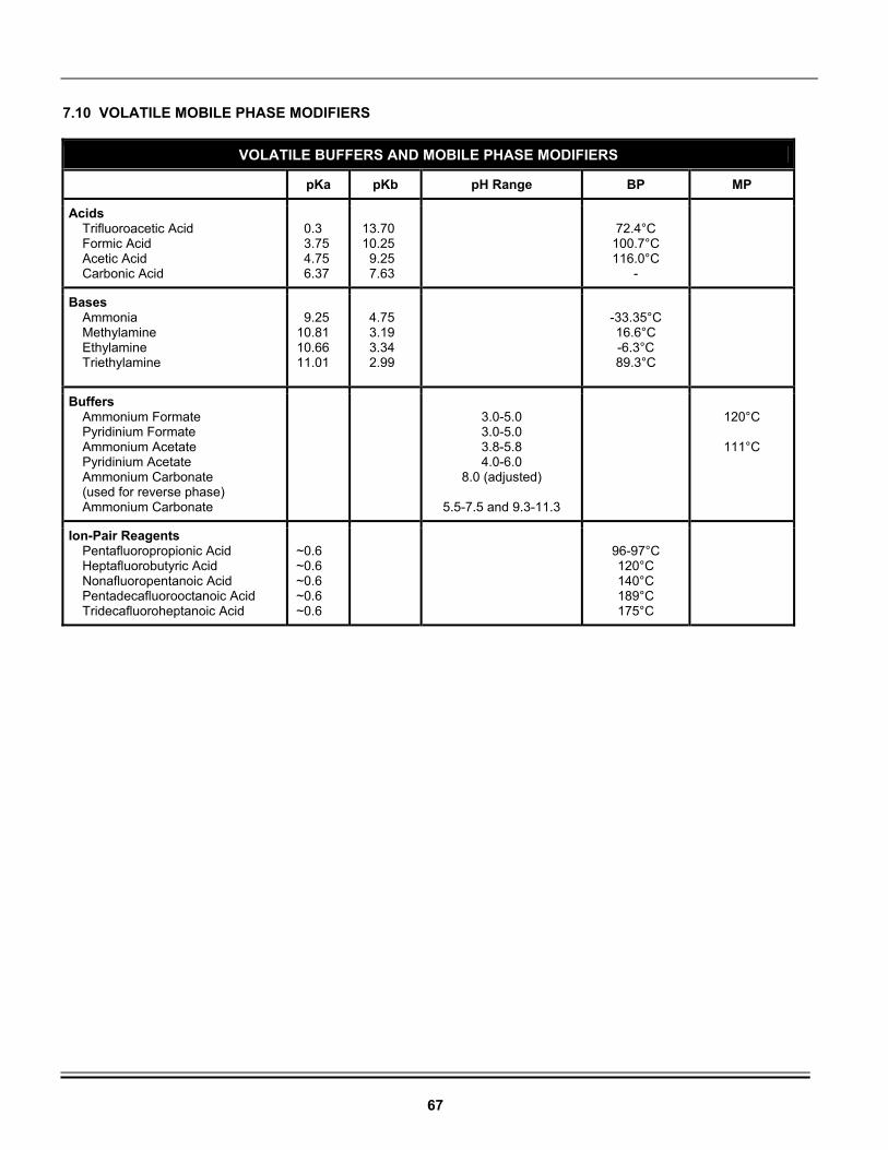
67
7.10 VOLATILE MOBILE PHASE MODIFIERS
VOLATILE BUFFERS AND MOBILE PHASE MODIFIERS
pKa pKb pH Range BP MP
Acids Trifluoroacetic Acid Formic Acid Acetic Acid Carbonic Acid
0.3 3.75 4.75 6.37
13.70 10.25 9.25 7.63
72.4°C
100.7°C 116.0°C
-
Bases Ammonia Methylamine Ethylamine Triethylamine
9.25
10.81 10.66 11.01
4.75 3.19 3.34 2.99
-33.35°C 16.6°C -6.3°C 89.3°C
Buffers Ammonium Formate Pyridinium Formate Ammonium Acetate Pyridinium Acetate Ammonium Carbonate (used for reverse phase) Ammonium Carbonate
3.0-5.0 3.0-5.0 3.8-5.8 4.0-6.0
8.0 (adjusted)
5.5-7.5 and 9.3-11.3
120°C
111°C
Ion-Pair Reagents Pentafluoropropionic Acid Heptafluorobutyric Acid Nonafluoropentanoic Acid Pentadecafluorooctanoic Acid Tridecafluoroheptanoic Acid
~0.6 ~0.6 ~0.6 ~0.6 ~0.6
96-97°C 120°C 140°C 189°C 175°C
68
7.11 WARRANTY, RETURNS, AND REPAIRS
WARRANTY
Grace Davison Discovery Sciences warrants its products against defects in workmanship or material under normal use or service for one year. All obligations or liabilities under this warranty are limited to repair or replacement, at Grace’s option, F.O.B. Deerfield, IL, of parts that are returned, freight prepaid and which are accepted as being defective upon inspection by Grace. Components that are subject to normal wear and/or are scheduled for routine replacement within the warranty period, and/or parts, which are subjected to effects of corrosion or deterioration by chemical or other action are excluded from the above warranty for malfunction because of inadequate facilities, operating conditions, or utilities. Equipment and components may only be returned with Grace’s prior approval and must bear a Grace Return Authorization Number. Call the Grace Customer Service Department to obtain a Return Authorization Number. Guarantee/Warranties on accessories and equipment included by Grace from other manufacturers are limited to the guarantees given on such equipment by the respective manufacturers. Any modifications made to equipment covered by this warranty, without written permission from Grace will void the warranty. Grace reserves the right not to honor this warranty if the products are obviously mishandled by the user. Grace assumes no responsibility for consequential, economic or incidental damages of any nature or on-site reinstallation costs arising out of future alleged failure of any of its products or their accessories. This warranty supersedes any and all previous warranties unless otherwise agreed upon at the time of sale, such as for customized equipment.
SHIPMENTS
All shipments are made F.O.B. Deerfield, IL. DAMAGED SHIPMENTS
The Interstate Commerce Commission has held that carriers are responsible for both concealed and visible damage occurring during transit. Unpack the shipment upon receipt and check for concealed damage even if no visible damage is apparent. If concealed damage is discovered, stop unpacking the unit, request an immediate inspection by the local carrier agent, and obtain a written report of the findings to support a claim. This request must be made within 15 days of receipt; otherwise, the claim will not be honored by the carrier. Do not return damaged goods to Grace without first obtaining an inspection report and calling Grace for a Return Authorization Number. FILING OF CLAIMS
After a damage inspection report has been obtained, Grace will cooperate in replacing damaged goods and in handling of claims, which have been initiated by either party. RETURNS
If it is necessary to return any material to Grace, please call Grace's Customer Service Department for a Return Authorization Number and forwarding instructions. No returns may be made without a Return Authorization Number. REPAIRS
Grace is the only organization authorized to service or repair the Model 3300 ELSD. Any repairs performed without notifying Grace will void the warranty. To obtain repair service, call Grace's Customer Service Department for instructions and a Return for Repair Number.
69
7.12 USEFUL REFERENCES
THEORY AND REVIEWS Evaporative Light Scattering Detection Solves Common HPLC Detection Problems, M.J. Wilcox, International Labmate, 23(6), 35-36 (1998). Modified Laser Light-Scattering Detector for Use in High Temperature Micro Liquid Chromatography, R. Trones, T. Andersen, I. Hunnes, and T. Greibrokk, Journal of Chromatography A, 814, 55-61 (1998). Improved Modification of Laser Light-Scattering Detector for Use in Packed Capillary High Temperature Liquid Chromatography, Roger Trones, Thomas Andersen, Tyge Greibrokk, Journal of High Resolution Chromatography, 22(5), 283-286 (1999). The Evaporative Light-Scattering Detector, S. L. Hansen and W.E. Artz, Inform, 6(2), 170-176 (1995). Detect Anything Your LC Separates, P.A. Asmus, Research. & Dev., 2, 96-98 (1993). Evaporative Light Scattering Detectors for HPLC, GPC, SEC, SFC - A Review, Bonnett, P.G., International LabMate, 15(5), 27-29 (1990). Use of Light-Scattering as a Detector Principle in Liquid Chromatography, A. Stolyhwo, H. Colin, G. Guiochon, Journal of Chromatography, 265, 1-18 (1983). A Light Scattering Detector for Liquid Chromatography, P.B. Stockwell, B.W. King, American Laboratory, 19-24 (August 1991). Evaporative Analyzer as a Mass Detector for Liquid Chromatography, John M. Charlesworth, Analytical Chemistry, 50(11), 1414-1420 (September 1978). Study of the Qualitative and Quantitative Properties of the Light Scattering Detector, A. Stolyhwo, H. Colin, M. Martin, G. Guiochon, Journal of Chromatography, 288, 253-275 (1984). Influence of Various Parameters on the Response Factors of the Evaporative Light Scattering Detector for a Number of Non-Volatile Compounds, Georges Guiochon, Anne Moysan, Christopher Holley, Journal of Liquid Chromatography, 11(12), 2547-2570 (1988). Effects of the Nature of the Solvent and Solutes on the Response of a Light Scattering Detector, Michel Righezza, Journal of Liquid Chromatography, 11(9 & 10), 1967-2004 (1988). Effects of Wavelength of the Laser Beam on the Response of an Evaporative Light Scattering Detector, Michel Righezza, Journal of Liquid Chromatography, 11(13), 2709-2729 (1988).
CARBOHYDRATE APPLICATIONS Analysis of Carbohydrates using the Mass Detector, R. Macrae and J. Dick, Journal of Chromatography, 210, 138-145 (1981). High-Performance Liquid Chromatographic Deter-mination of Mono- and Oligosaccharides in Vegetables with Evaporative Light-Scattering Detection and Refractive Index Detection, J. Lopez Hernandez, M.J. Gonzalez-Castro, I. Naya Alba, and C. de la Cruz Garcia, Journal of Chromatographic Science, 36, 292-298 (1998). GLYCERIDE, FATTY ACID, OIL APPLICATIONS Determination of Nonvolatile Components of Heated Soybean Oils Separated with High-Efficiency Mixed-Bed Polystyrene/Divinylbenzene Columns, S.L. Abidi, I.H. Kim, and K.A. Rennick, Journal of the American Oil Chemists' Society, 76(8), 939-944 (1999). Non-Aqueous Reversed-Phase High-Performance Liquid Chromatography of Synthetic Triacylglycerols and Diacylglycerols, J-T Lin, C.L. Woodruff, and T.A. McKeon, Journal of Chromatography A, 782, 41-48 (1997). Simulated Distillation of Heavy Oils Using an Evaporative Light Scattering Detector, D.M. Padlo and E.L. Kugler, Energy & Fuels, 10(5), 1031-1035 (1996). Fast Monitoring of C20 – C160 Crude Oil Alkanes by Size-Exclusion Chromatography-Evaporative Light Scattering Detection Performed with Silica Columns, L. Carbognani, Journal of Chromatography A, 788, 63-73 (1997). Analysis of Human Milk Triacylglycerols by High-Performance Liquid Chromatography with Light-Scattering Detection, S.M. Pons, A.I. Castellote Bargallo, and M.C. Lopez Sabater, Journal of Chromatography A, 823, 475-482 (1998). Evaluation by High-Performance Liquid Chromatography of the Hydrolysis of Human Milk Triacylglycerides During Storage at Low Temperatures, S.M. Pons, A.I. Castellote Bargallo, and M.C. Lopez Sabater, Journal of Chromatography A, 823, 467-474 (1998). Prediction of Relative Retention Times of Triacylglycerols in Non-Aqueous Reversed-Phase High-Performance Liquid Chromatography, J.-T. Lin, L.R. Snyder, and T.A. McKeon, Journal of Chromatography A, 808, 43-49 (1998). Analysis of Lipoxygenase Kinetics by High-Performance Liquid Chromatography with a Polymer Column, A. Nunez and G.J. Piazza, Lipids, 30(2), 129-133 (1995). Gradient Reversed-Phase High-Performance Liquid Chromatography of Saturated, Unsaturated and Oxygenated Free Fatty Acids and Their Methyl Esters, J.T. Lin, T.A. McKeon, and A.E. Stafford, Journal of Chromatography A, 699, 85-91 (1995).
70
Comparative High-Performance Liquid Chromatographic Analyses of Cholesterol and Its Oxidation Products Using Diode-Array Ultraviolet and Laser Light-Scattering Detection, S. Kermasha, S. Kubow, and M. Goetghebeur, Journal of Chromatography A, 685, 229-235 (1994). A Qualitative Method for Triglyceride Analysis by HPLC Using an ELSD, W.S. Letter, Journal of Liquid Chromatography, 16(1), 225-239 (1993). Fatty Acid Composition of Human Milk Triglyceride Species. Possible Consequences for Optimal Structures of Infant Formula Triglycerides, Cheil H. Winter, Edda B. Hoving, Frits A.J. Muskier, Journal of Chromatography, 616, 9-24 (1993). Analysis of Triglycerides in Oils and Fats by Liquid Chromatography with Laser Light-Scattering Detector, Andrzej Stolywho, Henri Colin, Georges Guiochon, Analytical Chemistry, 57, 1342-1354 (1985). Lipase G-Catalyzed Synthesis of Monoglycerides in Organic Solvent and Analysis by HPLC, Casmir Akoh, Carolyn Cooper, Chigozie Nwosu, Journal of the American Oil Chemists’ Society, 69(9), (March 1992). Determination of the Positional Distribution of Fatty Acids in Butter Fat Triacylglycerols, S. Kermasha, S. Kubow, M. Safari, A. Reid, Journal of Chromatographic Science, 70, 169-173 (1993). A New Variety of Low Linolenic Rapeseed Oil; Characteristics and Room Odor Tests, A. Prevot, J.L. Perin, G. Laclaverie, P.H. Auge, Coustille, J.L., Journal of the American Oil Chemists’ Society, 67(3), 161 (March 1990). Analysis of Tocopherols and Phytosterols in Vegetable Oils by HPLC with Evaporative Light Scattering Detection, K. Warner, T.L. Mounts, Journal of the American Oil Chemists’ Society, 67(11), (November 1990). Analysis of Dimer Acids Using HPLC and the Evaporative Light Scattering Detector, Peter Bonnett, Lipid Technology, 96-97 (July/August 1992). Comparison of Detectors for Size Exclusion Chromatography of Heavy Oil Related Samples, S. Coulombe, Journal of Chromatographic Science, 26: 1-6 (1988). LIPID APPLICATIONS Estimation of Free Glycolipids in Wheat Flour by HPLC, J.B. Ohm, and O.K. Chung, Cereal Chemistry, 76(6), 873-876 (1999). Fractionation of Soybean Phospholipids by High-Performance Liquid Chromatography with an Evaporative Light-Scattering Detector, Tong Wang, Earl G. Hammond, James L. Cornette, and Walter R. Fehr, Journal of the American Oil Chemists' Society, 76(11), 1313-1321 (1999).
Rapid Analysis of Oxidized Cholesterol Derivatives by High-Performance Chromatography Combined with Diode-Array Ultraviolet and Evaporative Laser Light-Scattering Detection, Kyoichi Osada, Amir Ravandi, and Arns Kuksis, Journal of the American Oil Chemists' Society, 76(7), 863-871 (1999). Reversed-Phase Separations of Nitrogenous Phospholipids on an Octadecanoyl Poly (Vinyl Alcohol) Phase, S.L. Abidi and T.L. Mounts, Journal of Chromatography A, 773, 93-101 (1997). Quantitative Analysis of Phosphatidylcholine Molecular Species using HPLC and Light Scattering Detection, Jos F.H.M. Brouwers, B.M. Gadella, L.M.G. van Golde, and A.G.M. Tielens, Journal of Lipid Research, 39, 1-10 (1998). Quantitative High-Performance Liquid Chromatography Analysis of Plant Phospholipids and Glycolipids Using Light-Scattering Detection, G.A. Picchioni, A.E. Watada, and B.D. Whitaker, Lipids, 31(2), 217-221 (1996). Separation of Synthetic Phosphatidylcholine Molecular Species by High-Performance Liquid Chromatography on a C8 Column, J-T Lin, C.L. Woodruff, T.A. McKeon, and J.A. Singleton, Journal of Chromatography A, 824, 169-174 (1998). New Procedures for Rapid Screening of Leaf Lipid Components from Arabidopsis, W.W. Christie, S. Gill, J. Nordback, Y. Itabashi, S. Sanda, and A.R. Slabas, Phytochemical Analysis, 9, 53-57 (1998). Characterization of Rabbit Myocardial Phospholipase A2 Activity Using Endogenous Phospholipid Substrates, O. Vesterqvist, C.A. Sargent, G.J. Grover, B. M. Warrack, G.C. DiDonato, and M.L. Ogletree, Analytical Biochemistry, 217, 210-219 (1994). Separation of Lipid Classes from Plant Tissues by High Performance Liquid Chromatography on Chemically Bonded Stationary Phases, W.W. Christie and R.A. Urwin, Journal of High Resolution Chromatography, 18, 97-100 (1995). Separation of Neutral Lipids by High-Performance Liquid Chromatography: Quantification by Ultraviolet, Light Scattering and Fluorescence Detection, E. J. Murphy, T. A. Rosenberger, and Lloyd A. Horrocks, Journal of Chromatography B, 685, 9-14 (1996). A Rapid Method for Phospholipid Separation by HPLC Using a Light-Scattering Detector, W.S. Letter, Journal of Liquid Chromatography, 15(2), 253-266 (1992). High Performance Liquid Chromatography of Lipids for the Identification of Human Metabolic Disease, Thomas C. Markello, Juanru Gu, and William A. Gahl, Analytic Biochemist, 198, 368-374 (1991). Detection of HPLC Separation of Glycophospholipids: Part 1, J.V. Amari, P.R. Brown, J.G. Turcotte, American Laboratory , 23-29 (February 1992).
71
Optimization of Detection for HPLC Separations of Glycerophospholipids: Part 2, J.V. Amari, P.R. Brown, J.G. Turcotte, American Laboratory, 26-33 (March 1992). HPLC Analysis of Phospholipids by Evaporative Light Scattering Detection, T.L. Mounts, S.L. Abidi, K.A. Rennick, Journal of the American Oil Chemists’ Society, 69(5), 438-432 (May 1992). High Performance Liquid Chromatography of Phosphatidic Acids and Related Polar Lipids, S.L. Abidi, Journal of Chromatography, 587, 193-203 (1991). An Improved Method for the Identification and Quantitation of Biological Lipids by HPLC Using Laser Light Scattering Detection, B.S. Lutzke, J.M. Braugler, Journal of Lipid Research, 31, 2127-2130 (1990). Rapid Separation and Quantification of Lipid Classes by High Performance Liquid Chromatography and Mass (Light Scattering) Detection, W.H. Christie, Journal of Lipid Research, 26: 507-512 (1985). Analysis of Neutral Lipids and Glycerolysis Products from Olive Oil by Liquid Chromatography, Baokang Yang, Jyhping Chen, Journal of the American Oil Chemist Society, 68(12), (December 1991). High-Performance Liquid Chromatographic Analysis of Wheat Flour Lipids Using an Evaporative Light Scattering Detector, F. Conforti, Carolyn H. Harris, Janet T. Rinehart, Journal of Chromatography, 645, 83-88 (1993). Determination of Cholesterol in Milk Fat by Reversed-Phase High Performance Liquid Chromatography and Evaporative Light Scattering Detection, George A. Spanos, Steven J. Schwartz, LC/GC, 10(10), 774-777 (1992). NUTRACEUTICAL/PHARMACEUTICAL APPLICATIONS
Determination of Fumonisins B1, B2, B3, and B4 by High-Performance Liquid Chromatography with Evaporative Light-Scattering Detection, J.G. Wilkes, J.B. Sutherland, M.I. Churchwell, and A.J. Williams, Journal of Chromatography A, 695, 319-323 (1995). High-Performance Liquid Chromatographic Analysis of Ginseng Saponins Using Evaporative Light Scattering Detection, M.K. Park, J.H. Park, S.B. Han, Y.G. Shin, and I.H. Park, Journal of Chromatography A, 736, 77-81 (1996). A Facile Separation of Nonactin and Its Homologues, T. Herlt, Journal of Liquid Chromatography and Related Technologies, 20(8), 1295-1300 (1997). Simultaneous Resolution and Detection of a Drug Substance, Impurities, and Counter Ion Using a Mixed-Mode HPLC Column with Evaporative Light Scattering Detection, M.D. Lantz, D.S. Risley, and J.A. Peterson, Journal of Liquid Chromatography & Related Technologies, 20(9), 1409-1422 (1997).
High-Throughput Characterization of Combinatorial Libraries Generated by Parallel Synthesis, J.N. Kyranos and J.C. Hogan, Analytical Chemistry, 70(1), 389A-395A (1998). Quantitation of Combinatorial Libraries of Small Organic Molecules by Normal-Phase HPLC with Evaporative Light-Scattering Detection, C.E. Kibbey, Molecular Diversity, 1(4), 247-258 (1996). An Alternative Method for the Determination of Chloride in Pharmaceutical Drug Substances Using HPLC and Evaporative Light-Scattering Detection, D.S. Risley, J.A. Peterson, K.L. Griffiths, and S. McCarthy, LC/GC, 14(12), 1040-1047 (1996). A High-Performance Liquid Chromatography Method for the Quantitation of Impurities in an NMDA Antagonist Using Evaporative Light Scattering Detection, D.S. Risley and J.A. Peterson, Journal of Liquid Chromatography, 18(15), 3035-3048 (1995). Trace Analysis of a Weak UV-Absorbing Pharmaceutical Compound in Swab Samples Using HPLC with Evaporative Light-Scattering Detection, D.S. Risley, K.F. Hostettler, and J.A. Peterson, LC/GC, 16(6),562-568 (1998). POLYMER AND SURFACTANT APPLICATIONS Universal Detection and Quantitation of Surfactants by High-Performance Liquid Chromatography by Means of the Evaporative Light-Scattering Detector, G.R. Bear, Journal of Chromatography, 459, 91-107 (1988). Chemical Characterization of Cellulose Acetate by Non-Exclusion Liquid Chromatography, T.R. Floyd, Journal of Chromatography, 629, 243-254 (1993). Acrylic Block Copolymer Analysis by Adsorption Chromatography with ELSD, B.L. Neff, H.J. Spinelli, Journal of Applied Polymer Science, 42, 595-600 (1991). Use of an Evaporative Light Scattering Detector in Reversed-Phase High-Performance Liquid Chrom-atography of Oligomeric Surfactants, Y. Mengerink, H.C. De Man, S.J. Van Der Wal, Journal of Chromatography, 552, 593-604 (1991).
72
MISCELLANEOUS APPLICATIONS Determination of the Mass Extractable in Organic Solvents by Light Scattering Detection, Katherine S. Hammond, Joanne Shatkin, Brian P. Leaderer, Applied Occupational Environmental Hygiene, 7(1), 49-54 (January 1992). Determination of Decyldimethyl Ammonium Chloride on Wood Surfaces by HPLC with Evaporative Light Scattering Detection, C.R. Daniels, Journal of Chromatographic Science, 30, 497-499 (December 1992).
Newer Method for the Characterization of Higher Molecular Mass Coal Derivatives, Keith D. Bartle, Erdol und Kohle - Erdgas - Petrocheme Vereinigt mit Brennstoff, 36(1), (January 1983).
ALLTECH® is a trademark, registered in the United States and/or other countries, of Alltech Associates, Inc. SOFGRIP™ is a trademark of Alltech Associates, Inc. GRACE® and GRACE DAVISON® are trademarks, registered in the United States and/or other countries, of W. R. Grace & Co.-Conn. GRACE DAVISON DISCOVERY SCIENCES™ is a trademark of W. R. Grace & Co.-Conn. WINDOWS® is a trademark of Microsoft Corporation. This trademark list has been compiled using available published information as of the publication date of this brochure and may not accurately reflect current trademark ownership. Grace Davison Discovery Sciences is a product group of W. R. Grace & Co.-Conn. Alltech Associates, Inc. is a wholly owned subsidiary of W. R. Grace & Co.-Conn. © Copyright 2007 Alltech Associates, Inc. All rights reserved.

73
Grace Davison Discovery Sciences Regional Headquarters In the Americas 2051 Waukegan Road • Deerfield, Illinois 60015-1899 Tel: 847.948.8600 • Fax: 847.948.1078 Email: [email protected] Web: www.discoverysciences.com In Europe Brandstraat 12 • B-9160 Lokeren, Belgium Tel: +32 (0)9 340 65 65 • Fax: +32 (0)9 340 65 60 Email: [email protected] Web: www.discoverysciences.com/be In Asia 19th Floor • K. Wah Center • 1010 Hua Hai Zhong Road Shanghai 200031, P.R.C. Tel: 86 21 54674678 • Fax: 86 21 54051500 Email: [email protected] Web: www.discoverysciences.com/cn In Australia 30 Brookhollow Avenue • Baulkham Hills New South Wales 2153, Australia Tel: 1300 36 24 12 • Fax: 1300 36 24 11 Email: [email protected] Web: www.discoverysciences.com/au
www.discoverysciences.com