Embed Size (px)
Citation preview
3.22.07
High Performance High Performance Piston Engine Piston Engine
OperationsOperations

3.22.07
Propeller BasicsPropeller Basics
• Like any airfoil, the propeller is most efficient at a specific angle of attack
• As the forward speed and RPM’s change, the relative wind experienced by the propeller comes from different angles
• The propeller changes its blade angle (pitch) so the AOA remains optimal

TakeoffTakeoff RotationRotation CruiseCruise2700 RPM2700 RPM
AS= 0 KTASAS= 0 KTAS
2700 RPM2700 RPM
AS= 80 KTASAS= 80 KTAS
2500 RPM2500 RPM
AS= 180 KTASAS= 180 KTAS
(2700 RPM, 2/3 of 78” Prop= 360 KTAS)(2700 RPM, 2/3 of 78” Prop= 360 KTAS) (2500 RPM= 330 KTAS)(2500 RPM= 330 KTAS)
Optimal AlphaOptimal AlphaOptimal AlphaOptimal Alpha Optimal AlphaOptimal Alpha
With Airspeed Increase, or RPM Decrease, Pitch Angle Increases, But Alpha Remains UnchangedWith Airspeed Increase, or RPM Decrease, Pitch Angle Increases, But Alpha Remains Unchanged
Variable Pitch Propeller In FlightVariable Pitch Propeller In Flight

ForwardForward
Variable Pitch Propeller In OperationVariable Pitch Propeller In Operation
Pressurized Pressurized Engine OilEngine Oil
Centrifugal Twisting ForceCentrifugal Twisting Force
X
CTFCTF Oil PressureOil Pressure
More Oil To Prop=More Oil To Prop=
Oil Pressure Stronger,Oil Pressure Stronger,
Piston Moves Aft,Piston Moves Aft,
Prop Pitch IncreasesProp Pitch Increases
Drain Oil From Prop=Drain Oil From Prop=
CTF Stronger,CTF Stronger,
Piston Moves Forward,Piston Moves Forward,
Prop Pitch DecreasesProp Pitch Decreases
Fixed CylinderFixed Cylinder
Movable PistonMovable Piston

Propeller Propeller HubHub
Propeller Governor OperationPropeller Governor Operation
Propeller Propeller HubHub
Propeller Propeller HubHub
To Engine To Engine SumpSump
Oil From Oil From PumpPump
OnspeedOnspeed OverspeedOverspeed UnderspeedUnderspeed
No oil flows to/ from propeller, No oil flows to/ from propeller, Pitch remains constantPitch remains constant
Oil flows to propeller, Oil flows to propeller, Pitch increases, RPM Pitch increases, RPM decreasesdecreases
Oil flows from propeller, Oil flows from propeller, Pitch decreases, RPM Pitch decreases, RPM increasesincreases
SpeederSpring

3.22.07
Propeller OverspeedPropeller Overspeed
• If oil pressure is lost, oil drains from prop hub
• Unopposed CTF causes the prop to move to its lowest pitch
• Prop is now taking a very small bite of air; is able to turn at higher RPM
• Prop will function as a fixed pitch prop; to lower RPM reduce:– Power– Airspeed
Propeller overspeeds or will not decrease:1. Power Lever ...........ADJUST (to keep RPM in limits)2. Airspeed....................................REDUCE to 90 KIAS3. Land as soon as practical.
Alpha

3.22.07
Engine Basics- Engine ControlsEngine Basics- Engine Controls
• Throttle-– Moves throttle plate– Constricts air to engine,
effectively reducing power
• Propeller– Adjusts tension on speeder
spring– Sets equilibrium RPM
• Mixture– Moves fuel proportioning valve– Changes fuel-air ratio sent to
engine
Combined into“Power Lever”

3.22.07
Cirrus Power LeverCirrus Power Lever
• First portion of travel adjusts propeller only- throttle remains full open.
• Then throttle is progressively closed, propeller left unchanged
Prop Throttle2700
2500
Full
Closing

3.22.07
Effect of Fuel MixtureEffect of Fuel Mixtureon Engine Parameterson Engine Parameters

3.22.07
Benefits of Operating Lean of PeakBenefits of Operating Lean of Peak
• More Fuel Efficient (Better BSFC)• Decreased CHT’s for same power• Lower Pressure in Cylinders for same
power• Cleaner Combustion
– Lower Deposits– Less “Washdown” of Cylinders– Less Carbon Monoxide Production

3.22.07
Definition of TermsDefinition of Terms
• Exhaust Gas Temperature (EGT)– Temperature of burned fuel and air charge,– Measured as it exits the cylinder,– Value not usually important, but rather indication
relative to other EGT’s or to peak EGT.
• Cylinder Head Temperature (CHT)– Temperature of each cylinder,– Value is important- lower temperatures are better,– Affected by power, mixture, airflow over the
cylinders.

3.22.07
50F LOP75F ROP
LEAN RICH

3.22.07
We lose 25 HP, or 8%
18.4 gph14.4 gph
50F LOP75F ROP
FF drops 4 GPH,or 22%

3.22.07
50F LOP75F ROP

3.22.07
50F LOP75F ROP

3.22.07
LEAN RICH
Changing power changes the absolute values of various parameters, however the relationship between mixture setting and the parameters remains the same at high or low power.
3.22.07
Heat and Pressure are the Two Heat and Pressure are the Two Greatest Enemies of an EngineGreatest Enemies of an Engine

3.22.07
~400 F- Absolute Limit
~380 F- “Working Limit”
CHT & Metal StrengthCHT & Metal Strength

3.22.07
EGT
CHT
ICP
HP1/
BSFC
LEAN RICH
50 LOP
50 ROP
Peak
ICP-Intra-Cylinder Pressure

3.22.07
Force
(Top Dead Center) (Peak of Pressure Pulse)

3.22.07
Peak Pressure Later LOP
Peak Pressure Lower LOP
Pressure At TDC Lower
LOP

3.22.07
Danger ZoneDanger Zone
• 80% 60 LOP- 200 ROP• 75% 40 LOP- 180 ROP• 70% 25 LOP- 125 ROP• 65% Peak EGT- 100 ROP• 60% No Danger Zone
• The “Danger Zone” is the range of mixture settings for a given power setting that results in unacceptable ICP.
• As power is reduced, DZ gets smaller, and eventually does not exist.
• Operate leaner than LOP end of DZ, or richer than ROP end of DZ for optimal engine health and safety

3.22.07
Fuel Distribution and Fuel/ Air Fuel Distribution and Fuel/ Air BalanceBalance
• In a perfect engine, all cylinders will receive exactly 1/6th the total fuel and air to be combusted
• Fuel injection ensures all cylinders get exactly 1/6th the fuel; however, induction system is not perfect, so air flow is uneven
• This causes all cylinders to be slightly richer or leaner than the others
• The closer the air distribution is to even, the smoother the engine will run, especially Lean-of-Peak

AIR
FUEL
Carbureted Vs. Fuel Injected SystemCarbureted Vs. Fuel Injected System
AIR
FUEL
CarburetedCarbureted Fuel InjectedFuel Injected
CarburetorCarburetor Servo Regulator (RSA)/ Servo Regulator (RSA)/ Fuel- Air Control Unit (TCM)Fuel- Air Control Unit (TCM)
Flow Divider (RSA)/ Flow Divider (RSA)/ Manifold Valve (TCM)Manifold Valve (TCM)

3.22.07
Power Difference
Engine Roughness at LOPEngine Roughness at LOP
•ROP- power curve is flatter, so variations in richness between cylinders does not cause significant variation in power produced by cylinders.
•LOP- steep power curve exaggerates effects of uneven fuel air distribution. Felt as roughness due to uneven power production by each cylinder, uneven push on crankshaft.

3.22.07
Prop
12
34
56
TCM Cylinder NumberingTCM Cylinder Numbering
3.22.07
In-flight Engine OperationsIn-flight Engine Operations
3.22.07
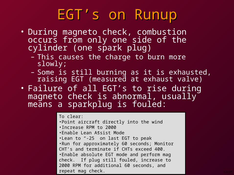
EGT’s on RunupEGT’s on Runup• During magneto check, combustion occurs
from only one side of the cylinder (one spark plug)– This causes the charge to burn more slowly;– Some is still burning as it is exhausted, raising
EGT (measured at exhaust valve)• Failure of all EGT’s to rise during magneto
check is abnormal, usually means a sparkplug is fouled:
To clear:•Point aircraft directly into the wind•Increase RPM to 2000•Enable Lean Assist Mode•Lean to “-25” on last EGT to peak•Run for approximately 60 seconds; Monitor CHT’s and terminate if CHTs exceed 400.•Enable absolute EGT mode and perform mag check. If plug still fouled, increase to 2000 RPM for additional 60 seconds, and repeat mag check.

3.22.07
ClimbClimb
~1000’ AGL
Lean
Placarded fuel flows can serve as double check, or backup if EGT is not normalized at 1000’.
Takeoff
As aircraft climbs, ambient air becomes less dense, and mixture becomes richer. ROP, richer = cooler EGT’s
3.22.07
Cruise- LOP (ASE SOP)Cruise- LOP (ASE SOP)
• Set initial power setting (normally 75%)
• Select “Lean Assist”
• Lean until all cylinders have peaked, then lean until desired LOP value is set above the last cylinder to peak– This ensures all other cylinders are leaner
than target, and outside DZ (they have all already passed peak EGT)

3.22.07
Cruise- ROPCruise- ROP
• Set initial power setting (normally 75%)
• Select “Lean Assist”
• Lean until first cylinder peaks, then richen until desired ROP value is set above the first cylinder to peak– This ensures all other cylinders are richer
than target, and outside DZ (they have not yet passed peak EGT)

3.22.07
DescentDescent
• From normal cruise altitudes, no adjustment to mixture is required on descent
• If engine roughness is encountered:– Reduce power to 65% or less, and– Enrichen slowly until roughness disappears