Embed Size (px)
Citation preview

Fujitsu Microelectronics Europe Application Note
MCU-AN-300012-E-V10
FR FAMILY 32-BIT MICROCONTROLLER
MB91460 SERIES
FLASH PROGRAMMING
APPLICATION NOTE

Serial Asynchronous Flash Programming Revision History
MCU-AN-300012-E-V10 - 2 - © Fujitsu Microelectronics Europe GmbH
Revision History
Date Issue 2006-01-30 V1.0 MVo - Initial Version
This document contains 25 pages.

Serial Asynchronous Flash Programming Warranty and Disclaimer
© Fujitsu Microelectronics Europe GmbH - 3 - MCU-AN-300012-E-V10
Warranty and Disclaimer To the maximum extent permitted by applicable law, Fujitsu Microelectronics Europe GmbH restricts its warranties and its liability for all products delivered free of charge (eg. software include or header files, application examples, target boards, evaluation boards, engineering samples of IC’s etc.), its performance and any consequential damages, on the use of the Product in accordance with (i) the terms of the License Agreement and the Sale and Purchase Agreement under which agreements the Product has been delivered, (ii) the technical descriptions and (iii) all accompanying written materials. In addition, to the maximum extent permitted by applicable law, Fujitsu Microelectronics Europe GmbH disclaims all warranties and liabilities for the performance of the Product and any consequential damages in cases of unauthorised decompiling and/or reverse engineering and/or disassembling. Note, all these products are intended and must only be used in an evaluation laboratory environment.
1. Fujitsu Microelectronics Europe GmbH warrants that the Product will perform substantially in accordance with the accompanying written materials for a period of 90 days form the date of receipt by the customer. Concerning the hardware components of the Product, Fujitsu Microelectronics Europe GmbH warrants that the Product will be free from defects in material and workmanship under use and service as specified in the accompanying written materials for a duration of 1 year from the date of receipt by the customer.
2. Should a Product turn out to be defect, Fujitsu Microelectronics Europe GmbH´s entire liability and the customer´s exclusive remedy shall be, at Fujitsu Microelectronics Europe GmbH´s sole discretion, either return of the purchase price and the license fee, or replacement of the Product or parts thereof, if the Product is returned to Fujitsu Microelectronics Europe GmbH in original packing and without further defects resulting from the customer´s use or the transport. However, this warranty is excluded if the defect has resulted from an accident not attributable to Fujitsu Microelectronics Europe GmbH, or abuse or misapplication attributable to the customer or any other third party not relating to Fujitsu Microelectronics Europe GmbH.
3. To the maximum extent permitted by applicable law Fujitsu Microelectronics Europe GmbH disclaims all other warranties, whether expressed or implied, in particular, but not limited to, warranties of merchantability and fitness for a particular purpose for which the Product is not designated.
4. To the maximum extent permitted by applicable law, Fujitsu Microelectronics Europe GmbH´s and its suppliers´ liability is restricted to intention and gross negligence.
NO LIABILITY FOR CONSEQUENTIAL DAMAGES
To the maximum extent permitted by applicable law, in no event shall Fujitsu Microelectronics Europe GmbH and its suppliers be liable for any damages whatsoever (including but without limitation, consequential and/or indirect damages for personal injury, assets of substantial value, loss of profits, interruption of business operation, loss of information, or any other monetary or pecuniary loss) arising from the use of the Product.
Should one of the above stipulations be or become invalid and/or unenforceable, the remaining stipulations shall stay in full effect
Serial Asynchronous Flash Programming Contents
MCU-AN-300012-E-V10 - 4 - © Fujitsu Microelectronics Europe GmbH
Contents
REVISION HISTORY............................................................................................................ 2
WARRANTY AND DISCLAIMER ......................................................................................... 3
CONTENTS .......................................................................................................................... 4
1 INTRODUCTION.............................................................................................................. 5
2 BACKGROUND INFORMATION ..................................................................................... 6 2.1 Connection to PC .................................................................................................... 6 2.2 Boot ROM ............................................................................................................... 6
3 FME-FR PROGRAMMER .............................................................................................. 10 3.1 Automatic Mode .................................................................................................... 10 3.2 Manual Mode (Step-by-Step)................................................................................. 12
4 FUJITSU FR FLASH PROGRAMMER........................................................................... 15 4.1 Full Operation........................................................................................................ 15 4.2 Manual (Step-by-step) Operation .......................................................................... 16
5 SK-91F467D-208PFV .................................................................................................... 17
6 SK-91460-MAIN WITH SK-91460-91F467D-208PFV .................................................... 19 6.1 Connection to SK-91460-MAIN ............................................................................. 19 6.2 Connection to SK-91460-91F467D-208PFV.......................................................... 21
7 APPENDIX..................................................................................................................... 24 7.1 Additional Documents ........................................................................................... 24 7.2 Figures .................................................................................................................. 24 7.3 Tables ................................................................................................................... 24

Serial Asynchronous Flash Programming Chapter 1 Introduction
© Fujitsu Microelectronics Europe GmbH - 5 - MCU-AN-300012-E-V10
1 Introduction This application note describes the serial asynchronous programming of the internal flash memory of the Fujitsu 32bit microcontrollers of the MB91460 series.
In the first chapter some basic information for the connection of the microcontroller to the PC and a short description of the internal Boot ROM of the MCU are given.
The second chapter describes the handling of the ‘FME-FR Programmer’.
In the third chapter another programming tool, the ‘Fujitsu FR Flash Programmer’, is explained.
The next chapters list the needed settings on the different starterkits for the flash derivates of the MB91460 series.
The last chapter gives some hints on additional literature.

Serial Asynchronous Flash Programming Chapter 2 Background Information
MCU-AN-300012-E-V10 - 6 - © Fujitsu Microelectronics Europe GmbH
2 Background Information
This chapter gives some information for connection of the microcontroller to the PC and the internal Boot ROM of the MCU.
2.1 Connection to PC For serial asynchronous programming of the internal Flash, UART channel 4 is used on MB91460 series flash devices. Therefore UART pins SIN4 (serial input) and SOT4 (serial output) have to be connected to the PC’s COM port via RS232 transceiver.
The figure below shows an example for this connection. You can also connect the RS232 signals DTR or RTS to the reset input of the microcontroller for controlling the reset signal by the programmer software.
Some terminal applications also need a connection between Pin 7 (RTS) and Pin 8 (CTS) on connector side.
Figure 1: Example of UART connection
Figure 2: RS232 Signal Connection
2.2 Boot ROM The Boot ROM is a fixed start-up routine, which is executed always after the Reset Cancellation Sequence of every INIT or RST reset if the device is configured with the mode pins set to MD[2:0]=”000” (internal ROM/vector mode).
GND DTR RxD TxD
CTS RTS DSR
1
6
5
9

Serial Asynchronous Flash Programming Chapter 2 Background Information
© Fujitsu Microelectronics Europe GmbH - 7 - MCU-AN-300012-E-V10
The purpose of the Boot ROM is to configure the device after a reset and to provide a simple serial bootloader for programming the embedded flash memories.
After the chip initialization and saving the RSRR (Reset Cause Register) to CPU register R4, there is a check for boot conditions. All Flash devices have two Boot Security Vectors (BSV1: 0x14:8004, BSV2: 0x14:800C). These vectors are located in parallel sector to the Flash Security Vectors (FSV1, FSV2):
Sector SA4 Sector SA5(8kB) (8kB)
… …0x14:8008 FSV2 BSV2 0x14:8000 FSV1 BSV1
At first, BSV1 is checked: if the data of this vector represents a valid address in the specified address range (depending on Flash-ROM size), the Boot Security Vector itself becomes valid.
Device Valid Boot Security Vector address range
MB91F467D 0x04:0000 – 0x14:FFFF
MB91F469G 0x04:0000 – 0x24:FFFF
MB91F464AA 0x0A:0000 – 0x0F:FFFF 0x14:8000 – 0x14:FFFF
MB91F465KA 0x08:0000 – 0x0F:FFFF 0x14:8000 – 0x14:FFFF
If BSV1 is valid, there will be an additional check before entering user program at the entry address given by BSV1 (1). Otherwise checks for entering the internal bootloader will be done (2).
The purpose of this feature is to disable the execution of the internal bootloader due to security reasons or to minimize startup time of application. If the user sets BSV1 to a valid address range, this bootloader cannot be entered any more.
(1) If the check for BSV1 is valid, the Magic Number, which should be located on the four bytes before the address BSV1 points to, is compared to 0x000A897A. If the Magic Number matches this value, the user application is entered at the address given by BSV1.
The Magic Number is used as flag for a valid user application, or especially for a user bootloader. If you want to re-program this user bootloader, a second user bootloader, which handles the re-programming of the first user bootloader, has to be located at the address BSV2 points to. If BSV2 does not point to a valid address range, then application is started at default user program entry address 0x0F:4000.
(2) If the check for BSV1 is not valid, the reset cause will be checked as second boot condition. Only if the reset cause was an INIT reset (external INITX input, RSRR=0x80), the check for boot conditions will go on. Otherwise Boot ROM is left and application is started at default user program entry address 0x0F:4000.
64bit width

Serial Asynchronous Flash Programming Chapter 2 Background Information
MCU-AN-300012-E-V10
If the reset cause was an INIT reset, serial clock pin SCK4 is checked for an external clock signal. Therefore logic level at this pin is monitored for about 1ms. If port level is constant, UART4 is initialized to asynchronous mode: 9600 baud, 8 data bits, 1 stop bit, no parity. If port level changes, UART4 is initialized to synchronous slave mode. UART-reception is checked for about 100 ms. If during this time period the ASCII-character “V” (0x56) is received, the internal bootloader is entered. Otherwise Boot ROM is left and application is also started at default user program entry address 0x0F:4000.
The following flow chart shows more detailed the checking conditions:
Figure 3: Flo
The internal bootloader provides some bRAM, function calling or changing the comused to write a programming kernel to thethe programming of the flash memory.
*1) Boot Security Vector points to address in Flash-ROM *2) Magic Number = 0x0A897A? *3) Start user application at address given by Boot Security Vector 1/2 *4) Start user application at default user program entry address *5) Timeout about 100 ms
- 8 - © Fujitsu Microelectronics Europe GmbH
w chart of Boot ROM
asic functions for reading and writing the internal munication speed. These functions are normally
internal RAM of the microcontroller which handles
Serial Asynchronous Flash Programming Chapter 2 Background Information
© Fujitsu Microelectronics Europe GmbH - 9 - MCU-AN-300012-E-V10
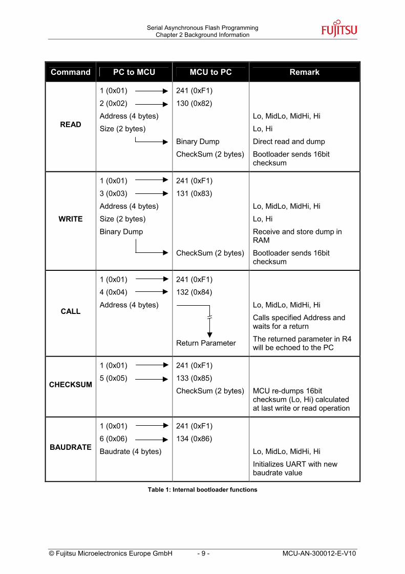
Command PC to MCU MCU to PC Remark
READ
1 (0x01)
2 (0x02)
Address (4 bytes)
Size (2 bytes)
241 (0xF1)
130 (0x82)
Binary Dump
CheckSum (2 bytes)
Lo, MidLo, MidHi, Hi
Lo, Hi
Direct read and dump
Bootloader sends 16bit checksum
WRITE
1 (0x01)
3 (0x03)
Address (4 bytes)
Size (2 bytes)
Binary Dump
241 (0xF1)
131 (0x83)
CheckSum (2 bytes)
Lo, MidLo, MidHi, Hi
Lo, Hi
Receive and store dump in RAM
Bootloader sends 16bit checksum
CALL
1 (0x01)
4 (0x04)
Address (4 bytes)
241 (0xF1)
132 (0x84)
Return Parameter
Lo, MidLo, MidHi, Hi
Calls specified Address and waits for a return
The returned parameter in R4 will be echoed to the PC
CHECKSUM
1 (0x01)
5 (0x05)
241 (0xF1)
133 (0x85)
CheckSum (2 bytes)
MCU re-dumps 16bit checksum (Lo, Hi) calculated at last write or read operation
BAUDRATE
1 (0x01)
6 (0x06)
Baudrate (4 bytes)
241 (0xF1)
134 (0x86)
Lo, MidLo, MidHi, Hi
Initializes UART with new baudrate value
Table 1: Internal bootloader functions

Serial Asynchronous Flash Programming Chapter 3 FME-FR Programmer
MCU-AN-300012-E-V10
3 FME-FR Programmer
This chapter explains the usage of the ‘FME-FR Programmer’ for serial asynchronous programming of the MB91460 series flash devices.
The ‘FME-FR Programmer’ is a serial asynchronous programming tool for the Fujitsu FR flash microcontrollers of the MB91360 and MB91460 series. It uses the internal bootloader functions to set up communication.
Figure 4: FME-FR Programmer Icon
There are two ways of programming:
• Automatic mode
• Manual mode (step-by-step)
3.1 Automatic Mode The automatic mode is the easiest way of using the programmer software. There are only some user settings needed on the “Automatic” sheet.
Figure 5
RESET MCU
- 10 - © Fujitsu Microelectronics Europe GmbH
: Settings for Automatic Mode

Serial Asynchronous Flash Programming Chapter 3 FME-FR Programmer
© Fujitsu Microelectronics Europe GmbH - 11 - MCU-AN-300012-E-V10
Choose the microcontroller device (e.g. “MB91F467D”) as device type and browse to the mhx-file you want to program to the embedded flash memory of the microcontroller. After that reset the microcontroller and press button “Automatic Mode” to start programming.
If your hardware supports MCU reset via DTR or RTS signal lines of the PC’s COM port, go to sheet “Signals” and select the appropriate reset signal line. The programmer now resets the microcontroller automatically before starting the programming sequence and you do not have to reset the MCU manually.
Figure 6: Reset Signal Settings
The software now automatically writes a flash loader to the microcontroller, does a blank check and erases the flash memory if necessary. After that the user application is programmed to the embedded flash memory.
During this sequence the actual progress status can be seen by checked off steps on the “Automatic” sheet and the messages below in the message box.
If the programming sequence is ended successfully, you will receive the output shown in figure 7.
MB91F467D:Addresses 0x14:8000 to 0x14:800F cannot be written in automatic mode. This is a built in security feature to prevent unintended writing to the Flash Security Vectors and Boot Security Vectors. Otherwise it would be possible to secure flash content and to lock the microcontroller for serial programming/reading/erasing by not being able to enter the internal loader anymore. If you want to use these features explicitly, you have to program these dedicated addresses by using the “Prog Word” Function of the step-by-step mode.

Serial Asynchronous Flash Programming Chapter 3 FME-FR Programmer
MCU-AN-300012-E-V10 - 12 - © Fujitsu Microelectronics Europe GmbH
Figure 7: Successful Programming in Automatic Mode
3.2 Manual Mode (Step-by-Step) The manual mode provides each function of the internal bootloader and the downloaded flash loader kernel as single steps.
Figure 8: Connect to internal bootloader
Serial Asynchronous Flash Programming Chapter 3 FME-FR Programmer
© Fujitsu Microelectronics Europe GmbH - 13 - MCU-AN-300012-E-V10
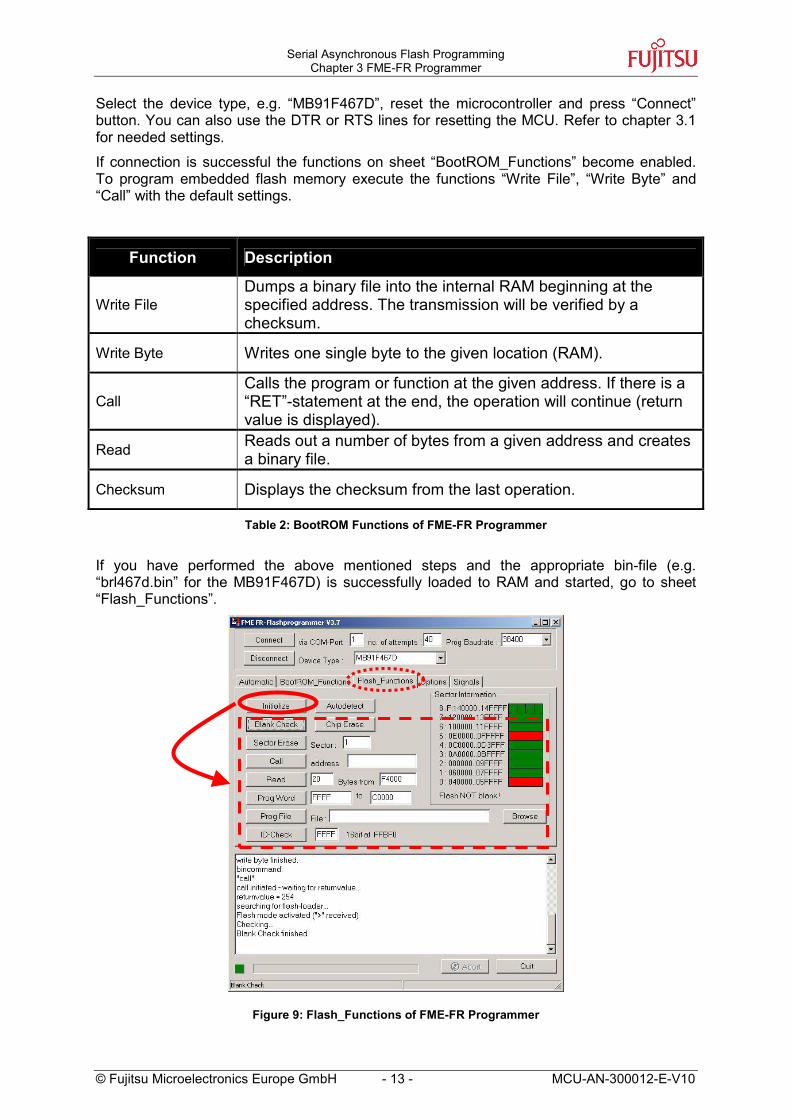
Select the device type, e.g. “MB91F467D”, reset the microcontroller and press “Connect” button. You can also use the DTR or RTS lines for resetting the MCU. Refer to chapter 3.1 for needed settings.
If connection is successful the functions on sheet “BootROM_Functions” become enabled. To program embedded flash memory execute the functions “Write File”, “Write Byte” and “Call” with the default settings.
Function Description
Write File Dumps a binary file into the internal RAM beginning at the specified address. The transmission will be verified by a checksum.
Write Byte Writes one single byte to the given location (RAM).
Call Calls the program or function at the given address. If there is a “RET”-statement at the end, the operation will continue (return value is displayed).
Read Reads out a number of bytes from a given address and creates a binary file.
Checksum Displays the checksum from the last operation.
Table 2: BootROM Functions of FME-FR Programmer
If you have performed the above mentioned steps and the appropriate bin-file (e.g. “brl467d.bin” for the MB91F467D) is successfully loaded to RAM and started, go to sheet “Flash_Functions”.
Figure 9: Flash_Functions of FME-FR Programmer

Serial Asynchronous Flash Programming Chapter 3 FME-FR Programmer
MCU-AN-300012-E-V10 - 14 - © Fujitsu Microelectronics Europe GmbH
Press button “Initialize”. If the command prompt of the flash loader is received, all the flash loader functions become enabled. See table 3 for a short description of each function. MB91460 series devices do not support “Autodetect” function!
Function Description
Initialize
Checks if the flash loader, which was dumped to RAM, is available, initialized at the correct baudrate and ready to operate. This function checks for a prompt character (“>”). If this operation fails (e.g. no flash loader present), none of the following functions will be enabled.
Blank Check Reads out every byte of each flash-sector to check for non-blank cells. The result is displayed in the flash-diagram on the right side (red = not blank sectors; green=blank sectors).
Chip Erase Erases the entire flash-ROM (all sectors).
Sector Erase Erases one sector indicated by the sector number.
Call This function will divert operation of the device to the specified location. This terminates the flash loader.
Prog Word Programs one word to flash at the specified address.
Prog File Handles the transfer of the specified MHX-file to the flash loader.
Read Reads out a given number of bytes beginning at the specified address and displays the results in hexadecimal format on the log-window.
Table 3: Flash Loader Functions of FME-FR Programmer
To program user application to the flash memory browse to correct mhx-file and use “Prog File” function. After successful programming press “Disconnect” button to close COM port.
For further information on the FME-Flash Programmer software please refer to the user guide.

Serial Asynchronous Flash Programming Chapter 4 Fujitsu FR Flash Programmer
© Fujitsu Microelectronics Europe GmbH - 15 - MCU-AN-300012-E-V10
4 Fujitsu FR Flash Programmer
This chapter explains the usage of the ‘Fujitsu FR Flash Programmer’ for serial asynchronous programming of the MB91460 series flash devices.
The ‘Fujitsu FR Flash Programmer’ is a serial asynchronous programming tool for the Fujitsu FR flash microcontrollers. It supports a lot of FR series.
Figure 10: Fujitsu FR Flash Programmer Icon
There are two ways of programming:
• Full Operation
• Manual (step-by-step)
4.1 Full Operation Full Operation is the easiest way to use this programmer software. You only have to select the (e.g. “MB91F467D”) as target microcontroller device and the mhx-file you want to program to the embedded flash memory.
Figure 11: Fujitsu FR Flash Programmer Full Operation 1

Serial Asynchronous Flash Programming Chapter 4 Fujitsu FR Flash Programmer
MCU-AN-300012-E-V10 - 16 - © Fujitsu Microelectronics Europe GmbH
Press button “Full Operation”. A new window pops up which gives the order to reset the microcontroller. Reset the MCU and the software starts the sequences of the programming progress. In case of a blank chip, processing is performed in order of Download, Blank Check, and Program & Verify. When it is not a blank chip, processing is performed in order of Download, Blank Check, Erase, Blank Check, and then Program & Verify. The actual status can be seen on the progress bars.
Figure 12: Fujitsu FR Flash Programmer Full Operation 2
4.2 Manual (Step-by-step) Operation The above mentioned steps can also be executed as single steps. But nevertheless, as first operation always the Download function has to be executed to set up communication and to write flash loader kernel to RAM.
Function Description
Download Sets up communication and downloads flash loader kernel to RAM.
Erase Does a chip erase of the flash memory.
Blank Check Checks that all flash memory areas are blank.
Program & Verify Writes the selected mhx-file to flash ROM and does block wise CRC checking.
Read & Compare Reads out flash memory and compares content with selected mhx-file.
Copy Reads out flash memory and writes it to mhx-file.
Table 4: Functions of Fujitsu FR Flash Programmer

Serial Asynchronous Flash Programming Chapter 5 SK-91F467D-208PFV
© Fujitsu Microelectronics Europe GmbH - 17 - MCU-AN-300012-E-V10
5 SK-91F467D-208PFV
This chapter describes the needed settings for programming the MB91F467D on the starterkit SK-91F467D-208PFV.
The starterkit SK-91F467D-208PFV is a multifunctional development board for the FUJITSU 32bit flash microcontroller MB91F467D in QFP208 package. It can be used stand-alone for software development and testing or together with a monitor debugger software.
Figure 13: Connection to starterkit SK-91F467D-208PFV
For serial asynchronous programming SUB-D9 connector X4 which is connected to UART4 has to be used. Following jumper setting is needed:
Jumper Setting Description
JP60 1-2 closed MCU SIN4 connected to RS-232 transceiver
JP65 1-2 closed MCU SOT4 connected to RS-232 transceiver
JP69 1-2 closed X4 pin2 is connected to RS-232 transceiver
Table 5: Jumper setting on starterkit SK-91F467D-208PFV

Serial Asynchronous Flash Programming Chapter 5 SK-91F467D-208PFV
If your programming software needs connection of RTS and CTS or if it generates reset signal on RTS or DTR line, refer to the following jumper list:
Jumper Setting Description
closed RTS and CTS is shortcut at connector X4 JP58
open RTS and CTS is not shortcut at connector X4
1-2 closed DTR can be used for system reset JP64
2-3 closed RTS can be used for system reset
JP57 3-4 closed Reset will be done via UART4
1-2 closed No polarity inversion for the DTR/RTS signal JP29
2-3 closed Polarity inversion for the DTR/RTS signal
Table 6: Jumper settings for reset signal on starterkit SK-91F467D-208PFV
JP29
MCU-AN-300012-E-V10 - 18 - © Fujitsu Microelectronics Europe G
Figure 14: Jumper setting on starterkit SK-91F467D-208PFV
JP5
JP58
J7J
X4
mbH
P60 JP64 P65 JP69
Serial Asynchronous Flash Programming Chapter 6 SK-91460-MAIN with SK-91460-91F467D-208PFV
© Fujitsu Microelectronics Europe GmbH - 19 - MCU-AN-300012-E-V10
6 SK-91460-MAIN with SK-91460-91F467D-208PFV
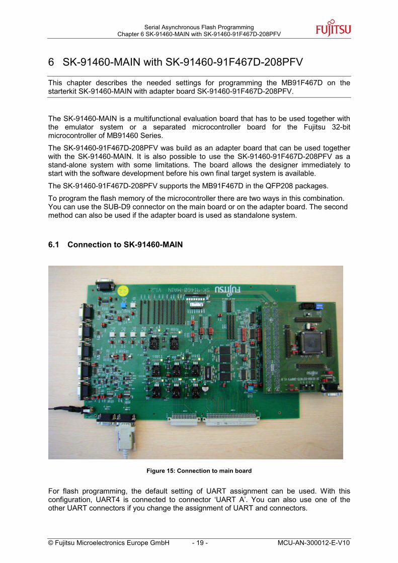
This chapter describes the needed settings for programming the MB91F467D on the starterkit SK-91460-MAIN with adapter board SK-91460-91F467D-208PFV.
The SK-91460-MAIN is a multifunctional evaluation board that has to be used together with the emulator system or a separated microcontroller board for the Fujitsu 32-bit microcontroller of MB91460 Series.
The SK-91460-91F467D-208PFV was build as an adapter board that can be used together with the SK-91460-MAIN. It is also possible to use the SK-91460-91F467D-208PFV as a stand-alone system with some limitations. The board allows the designer immediately to start with the software development before his own final target system is available.
The SK-91460-91F467D-208PFV supports the MB91F467D in the QFP208 packages.
To program the flash memory of the microcontroller there are two ways in this combination. You can use the SUB-D9 connector on the main board or on the adapter board. The second method can also be used if the adapter board is used as standalone system.
6.1 Connection to SK-91460-MAIN
Figure 15: Connection to main board
For flash programming, the default setting of UART assignment can be used. With this configuration, UART4 is connected to connector ‘UART A’. You can also use one of the other UART connectors if you change the assignment of UART and connectors.

Serial Asynchronous Flash Programming Chapter 6 SK-91460-MAIN with SK-91460-91F467D-208PFV
MC
Table 7 shows the default settings for UART4 with connector ‘UART A’.
Jumper Setting Description
ST1300 – Pin 1
UART ”A”: SOT ST1301 - Pin 4 UART “A” is connected to SOT 4
ST1303 – Pin 1
UART ”A”: SIN ST1304 - Pin 4 UART “A” is connected to SIN 4
ST1009 UART/LIN “A” 1-2 LIN/UART “A” uses the RS232 output
Table 7: Jumper setting for connection on main board
If your programming software expects connection of RTS and CTS signal, close jumper ST1007. Connection does not support a reset of microcontroller via RTS or DTR signal.
Jumper Setting Description
ON (closed) RTS and CTS is shortcut on UART “A” / SL1000 ST1007
UART ”A”: RTS-CTSOFF (open) RTS and CTS is not shortcut
Table 8: Additional jumper setting on main board
UART1
ST13
00ST
1301
ST13
02
ST13
03ST
1304
ST13
05
ST1009 ST1007
U-
UART A
AN-300012-E-V10 - 20 - © Fujitsu Microelectronics Europe GmbH
Figure 16: Jumper setting for connection with main board
UART2
UART3
UART4
.
.
UART15
UART ’A’
UART ’B’
UART ’C’
UART ’D’
LIN ’A’
LIN ’B’
LIN ’C’
LIN ’D’
SOT SIN

Serial Asynchronous Flash Programming Chapter 6 SK-91460-MAIN with SK-91460-91F467D-208PFV
© Fujitsu Microelectronics Europe GmbH - 21 - MCU-AN-300012-E-V10
6.2 Connection to SK-91460-91F467D-208PFV
Figure 17: SK-91460-MAIN with adapter board SK-91460-91F467D-208PFV
On the adapter board a SUB-D9 female connector and a RS232 transceiver is mounted. Refer to figure below for connection.
Figure 18: Connection on adapter board

Serial Asynchronous Flash Programming Chapter 6 SK-91460-MAIN with SK-91460-91F467D-208PFV
MCU-AN-300012-E-V10 - 22 - © Fujitsu Microelectronics Europe GmbH
To use the SUB-D9 connector (X5) on the adapter board, following jumpers have to be set:
Jumper Setting Description
JP4 (SOT) 2 – 3 closed SOT4 connected to RS232-Transceiver/SUB-D9 connector on adapter board
JP5 (SIN) 2 – 3 closed SIN4 connected to RS232-Transceiver/SUB-D9 connector on adapter board
JP11 (URXD) closed URXD (receive data SIN4) connected to MAX3232 R1OUT
JP13 (UTXD) closed UTXD (transmit data SOT4) connected to MAX3232 T1IN
Table 9: Jumper setting for connection to adapter board
If you want to use RS232 signals RTS or DTR to reset microcontroller by programming software (e.g. FME-FR Programmer) please check the following table for needed jumper setting:
Jumper Setting Description
JP12 (URST) closed URST (INITX) connected to MAX3232 R2OUT
closed X5 Pin8 (CTS) connected with X5 Pin7 (RTS) JP9 (RTS/CTS)
open X5 Pin8 (CTS) disconnected with X5 Pin7 (RTS)
open MAX 3232 R2input NC
1 – 2 closed SUB-D X5 Pin4 DTR (data terminal ready) and 6 DSR (data set ready) are connected to R2input -> reset by DTR signal
JP10 (DTR/DSR)
2 – 3 closed SUB-D X5 Pin7 RTS (and Pin 8 CTS) are connected to R2input -> reset by RTS signal
Table 10: Jumper setting for reset signals on adapter board

Serial Asynchronous Flash Programming Chapter 6 SK-91460-MAIN with SK-91460-91F467D-208PFV
© Fujitsu Microelectronics Europe G
Figur
JP10 JP9
JP11 JP13 JP12
mbH - 23 -
e 19: Jumper setting on adapter bo
JP4JP5
X5
MCU-AN-300012-E-V10
ard

Serial Asynchronous Flash Programming Chapter 7 Appendix
MCU-AN-300012-E-V10 - 24 - © Fujitsu Microelectronics Europe GmbH
7 Appendix
7.1 Additional Documents User Guide for
• FME-FR Programmer (FME_FR_FLASH_Programmer_Vxx.pdf)
• Fujitsu FR Flash Programmer (PCWFRe.pdf)
• Starterkit SK-91F467D-208PFV (ug-910014-xx-sk-91f467d-208pfv.pdf)
• Starterkit SK-91460-MAIN (ug-910010-xx-SK-91460-Main.pdf)
• Adapter board SK-91460-91F467D-208PFV (ug-910018-xx-SK-91460-91F467D-208PFV.pdf)
7.2 Figures Figure 1: Example of UART connection ................................................................................. 6 Figure 2: RS232 Signal Connection ....................................................................................... 6 Figure 3: Flow chart of BootROM........................................................................................... 8 Figure 4: FME-FR Programmer Icon .................................................................................... 10 Figure 5: Settings for Automatic Mode ................................................................................. 10 Figure 6: Reset Signal Settings............................................................................................ 11 Figure 7: Successful Programming in Automatic Mode ........................................................ 12 Figure 8: Connect to internal bootloader .............................................................................. 12 Figure 9: Flash_Functions of FME-FR Programmer............................................................. 13 Figure 10: Fujitsu FR Flash Programmer Icon...................................................................... 15 Figure 11: Fujitsu FR Flash Programmer Full Operation 1 ................................................... 15 Figure 12: Fujitsu FR Flash Programmer Full Operation 2 ................................................... 16 Figure 13: Connection to starterkit SK-91F467D-208PFV .................................................... 17 Figure 14: Jumper setting on starterkit SK-91F467D-208PFV.............................................. 18 Figure 15: Connection to main board ................................................................................... 19 Figure 16: Jumper setting for connection with main board ................................................... 20 Figure 17: SK-91460-MAIN with adapter board SK-91460-91F467D-208PFV ..................... 21 Figure 18: Connection on adapter board.............................................................................. 21 Figure 19: Jumper setting on adapter board......................................................................... 23
7.3 Tables Table 1: Internal bootloader functions .................................................................................... 9 Table 2: BootROM Functions of FME-FR Programmer ........................................................ 13 Table 3: Flash Loader Functions of FME-FR Programmer ................................................... 14

Serial Asynchronous Flash Programming Chapter 7 Appendix
© Fujitsu Microelectronics Europe GmbH - 25 - MCU-AN-300012-E-V10
Table 4: Functions of Fujitsu FR Flash Programmer ............................................................ 16 Table 5: Jumper setting on starterkit SK-91F467D-208PFV................................................. 17 Table 6: Jumper settings for reset signal on starterkit SK-91F467D-208PFV ....................... 18 Table 7: Jumper setting for connection on main board ......................................................... 20 Table 8: Additional jumper setting on main board................................................................. 20 Table 9: Jumper setting for connection to adapter board...................................................... 22 Table 10: Jumper setting for reset signals on adapter board................................................ 22