Embed Size (px)
Citation preview

31U10/H04LP1/VG-31U10/H04LP1/VG-11
31U10/H04LP1 31U10/H04LP1 INTRODUCTION TO INTRODUCTION TO
IMPROVED HIGH FREQUENCY IMPROVED HIGH FREQUENCY RADIOS (IHFR)RADIOS (IHFR)

31U10/H04LP1/VG-31U10/H04LP1/VG-22
RADIO SET AN/PRC-104A RADIO SET AN/PRC-104A CHARACTERISTICS/COMPONENTS CHARACTERISTICS/COMPONENTS

31U10/H04LP1/VG-31U10/H04LP1/VG-33
• Characteristics:Characteristics:
- Single Sideband (SSB), - Single Sideband (SSB), Amplitude Modulation (AM) Radio.Amplitude Modulation (AM) Radio.
- Operates on Upper Sideband (USB) - Operates on Upper Sideband (USB) Or Lower Sideband (LSB).Or Lower Sideband (LSB).
- High Frequency (HF) Range - High Frequency (HF) Range 2.0 To 29.9999 Mhz.2.0 To 29.9999 Mhz.
- Power Output 20 Watts.- Power Output 20 Watts.
RADIO SET AN/PRC-104A (1)RADIO SET AN/PRC-104A (1)

31U10/H04LP1/VG-31U10/H04LP1/VG-44
RADIO SET AN/PRC-104A (2)RADIO SET AN/PRC-104A (2)
- Power Supply:- Power Supply:
BA-5590 (24 to 32 Volts DC)BA-5590 (24 to 32 Volts DC)
- Planning Range:- Planning Range:
Whip (Omnidirectional) - 10 MilesWhip (Omnidirectional) - 10 Miles Dipole (Directional) - 300 MilesDipole (Directional) - 300 Miles

31U10/H04LP1/VG-31U10/H04LP1/VG-55
RECEIVER/EXCITER (RT-1209) (1)RECEIVER/EXCITER (RT-1209) (1)
Receiver/Receiver/ExciterExciter
LatchLatch
LatchLatch
31U10/H04LP1/VG-31U10/H04LP1/VG-66
• Four Modes of Operation.Four Modes of Operation.
- V-RCV. (Voice and IMC)- V-RCV. (Voice and IMC)
- V-TR. (Voice and IMC)- V-TR. (Voice and IMC)
- D-RCV. (Data)- D-RCV. (Data)
- D-TR. (Data)- D-TR. (Data)
RECEIVER/EXCITER (RT-1209) (2)RECEIVER/EXCITER (RT-1209) (2)

31U10/H04LP1/VG-31U10/H04LP1/VG-77
• Frequency Display MHz/kHz.Frequency Display MHz/kHz.
• Volume OFF/MAX Control.Volume OFF/MAX Control.
• Light Button.Light Button.
• Audio Connector (Upper and Lower).Audio Connector (Upper and Lower).
• SB Switch.SB Switch.
- USB.- USB. - LSB.- LSB.
RECEIVER/EXCITER (RT-1209) (3)RECEIVER/EXCITER (RT-1209) (3)

31U10/H04LP1/VG-31U10/H04LP1/VG-88
AMPLIFIER COUPLER (RF) AM-AMPLIFIER COUPLER (RF) AM-6874 (1)6874 (1)
31U10/H04LP1/VG-31U10/H04LP1/VG-99
• Boosts RT Power (3/10th Watt) to 20 Watts.Boosts RT Power (3/10th Watt) to 20 Watts.
• Has Built in Tuner, Which Will Tune the RadioHas Built in Tuner, Which Will Tune the Radio In Approximately 3 Seconds.In Approximately 3 Seconds.
AMPLIFIER COUPLER (RF) AM-AMPLIFIER COUPLER (RF) AM-6874 (2)6874 (2)

31U10/H04LP1/VG-31U10/H04LP1/VG-1010
• Antenna Selector SwitchAntenna Selector Switch - Whip (Omnidirectional) Upper Left.- Whip (Omnidirectional) Upper Left.
- Dipole (Directional) Center.- Dipole (Directional) Center.
- 50 Ohm (Lower Right); This Will Bypass- 50 Ohm (Lower Right); This Will Bypass The Tuner Should It Become Defective.The Tuner Should It Become Defective. Radio Will Still Operate As a Transceiver.Radio Will Still Operate As a Transceiver.
AMPLIFIER COUPLER (RF) AM-AMPLIFIER COUPLER (RF) AM-6874 (3)6874 (3)

31U10/H04LP1/VG-31U10/H04LP1/VG-1111
RADIO SET AN/GRC-213 (1)RADIO SET AN/GRC-213 (1)

31U10/H04LP1/VG-31U10/H04LP1/VG-1212
• Characteristics/ComponentsCharacteristics/Components
- Single Sideband (SSB), Amplitude- Single Sideband (SSB), Amplitude Modulation (AM) Radio.Modulation (AM) Radio.
- Operates on Upper Sideband (USB) - Operates on Upper Sideband (USB) Or Lower Sideband (LSB).Or Lower Sideband (LSB).
- High Frequency (HF) - High Frequency (HF) Range 2.0 To 29.9999 Mhz. Range 2.0 To 29.9999 Mhz. Tunes 280,000 Different Frequencies Tunes 280,000 Different Frequencies Within This Range.Within This Range.
RADIO SET AN/GRC-213 (2)RADIO SET AN/GRC-213 (2)

31U10/H04LP1/VG-31U10/H04LP1/VG-1313
• Power Output 20 Watts.Power Output 20 Watts.
• Power SupplyPower Supply
- BA-5590 (24 to 32 VDC)- BA-5590 (24 to 32 VDC)
• Planning RangePlanning Range
- Whip (Omnidirectional) - 10 Miles.- Whip (Omnidirectional) - 10 Miles. - Dipole (Directional) - 300 Miles. - Dipole (Directional) - 300 Miles.
RADIO SET AN/GRC-213 (3)RADIO SET AN/GRC-213 (3)

31U10/H04LP1/VG-31U10/H04LP1/VG-1414
• Additional Information:Additional Information:
- HF Low Power Transceiver.- HF Low Power Transceiver.
- Designed for Use on Wheeled or Tracked - Designed for Use on Wheeled or Tracked Vehicles.Vehicles.
- Internal Antenna Tuner Automatically Tunes- Internal Antenna Tuner Automatically Tunes Radio to Match Antenna Within Operating Radio to Match Antenna Within Operating Frequency Range.Frequency Range.
RADIO SET AN/GRC-213 (4)RADIO SET AN/GRC-213 (4)
31U10/H04LP1/VG-31U10/H04LP1/VG-1515
• Components:Components:
- Same As the AN/PRC-104A Except For- Same As the AN/PRC-104A Except For The Addition of the Amplifier Power SupplyThe Addition of the Amplifier Power Supply (AM-7152) and Antenna Switching Unit (SA-2365).(AM-7152) and Antenna Switching Unit (SA-2365).
RADIO SET AN/GRC-213 (5)RADIO SET AN/GRC-213 (5)

31U10/H04LP1/VG-31U10/H04LP1/VG-1616
POWER AMPLIFIER (AM-7152) POWER AMPLIFIER (AM-7152) (1)(1)

31U10/H04LP1/VG-31U10/H04LP1/VG-1717
• Provides Interface and Isolation BetweenProvides Interface and Isolation Between AN/PRC-104A and Speaker LS-454.AN/PRC-104A and Speaker LS-454.
• Receives Power Input Via CX-4720. Receives Power Input Via CX-4720.
• Provides Auxiliary Power for Another Radio Set.Provides Auxiliary Power for Another Radio Set.
POWER AMPLIFIER (AM-7152) POWER AMPLIFIER (AM-7152) (2)(2)

31U10/H04LP1/VG-31U10/H04LP1/VG-1818
• Conditions and Filters the Power to ProtectConditions and Filters the Power to Protect AN/GRC-213 From: AN/GRC-213 From:
- Over-Voltage- Over-Voltage - Noise Spike Transients - Noise Spike Transients - Radio Frequency Interference (RFI)- Radio Frequency Interference (RFI) - Reverse Polarity- Reverse Polarity
POWER AMPLIFIER (AM-7152) POWER AMPLIFIER (AM-7152) (3)(3)

31U10/H04LP1/VG-31U10/H04LP1/VG-1919
• Interfaces With AN/VIC-1 to Provide Interfaces With AN/VIC-1 to Provide Remote Handset Operation.Remote Handset Operation.
• Interfaces With AN/VIC-1 and VHF FMInterfaces With AN/VIC-1 and VHF FM Radio Sets to Provide Retransmission Capabilities.Radio Sets to Provide Retransmission Capabilities. Connects to J102. Connects to J102.
POWER AMPLIFIER (AM-7152) POWER AMPLIFIER (AM-7152) (4)(4)

31U10/H04LP1/VG-31U10/H04LP1/VG-2020
ANTENNA SWITCHING UNIT (SA-ANTENNA SWITCHING UNIT (SA-2365) (1)2365) (1)

31U10/H04LP1/VG-31U10/H04LP1/VG-2121
• Component of Installation Kit and Mounting Base.Component of Installation Kit and Mounting Base.
• Allows for Selection of Antenna:Allows for Selection of Antenna:
- Omnidirectional Whip- Omnidirectional Whip2 - 102 - 1010 - 3010 - 30
- Directional- DirectionalAN/GRA-50 (Doublet)AN/GRA-50 (Doublet)NVISNVISLong WireLong Wire
ANTENNA SWITCHING UNIT (SA-ANTENNA SWITCHING UNIT (SA-2365) (2)2365) (2)

31U10/H04LP1/VG-31U10/H04LP1/VG-2222
RADIO SET AN/GRC-193 (1)RADIO SET AN/GRC-193 (1)
Antenna CouplerAntenna CouplerCU-2064/GRC-193ACU-2064/GRC-193A Power AmplifierPower Amplifier
AM-6545A/GRC-193AAM-6545A/GRC-193A
Mounting BaseMounting BaseMT-6232/MT-6232/GRC-193AGRC-193A
Amplifier ConverterAmplifier ConverterAM-6879/URCAM-6879/URC
Receiver-TransmitterReceiver-TransmitterRT-1209/URCRT-1209/URC

31U10/H04LP1/VG-31U10/H04LP1/VG-2323
• Characteristics/ComponentsCharacteristics/Components
- Single Sideband (SSB), - Single Sideband (SSB), Amplitude Modulation (AM) Radio.Amplitude Modulation (AM) Radio.
- Operates on Uper Sideband (USB) - Operates on Uper Sideband (USB) or Lower Sideband (LSB).or Lower Sideband (LSB).
- High Frequency (HF) - High Frequency (HF) Range 2.0 to 29.9999 MHz.Range 2.0 to 29.9999 MHz.
RADIO SET AN/GRC-193 (2)RADIO SET AN/GRC-193 (2)

31U10/H04LP1/VG-31U10/H04LP1/VG-2424
• Power Output 100 or 400 Watts. Power Output 100 or 400 Watts.
NOTENOTE: For Classroom Purpose, Use 100: For Classroom Purpose, Use 100 Watt Position.Watt Position.
• Power Requirement to Operate Power Requirement to Operate
20 to 32 VDC.20 to 32 VDC.
RADIO SET AN/GRC-193 (3)RADIO SET AN/GRC-193 (3)

31U10/H04LP1/VG-31U10/H04LP1/VG-2525
• Planning Range.Planning Range.
- Whip Antenna - 10 Miles.- Whip Antenna - 10 Miles. - Dipole Antenna - 300 Miles.- Dipole Antenna - 300 Miles.
NOTE: The AN/GRC-193 Antenna Can Be RemotedNOTE: The AN/GRC-193 Antenna Can Be Remoted Up to 200 Feet Using an Antenna Siting Kit.Up to 200 Feet Using an Antenna Siting Kit.
• Secure Operations Use a KY-65 or KY-99.Secure Operations Use a KY-65 or KY-99.
RADIO SET AN/GRC-193 (4)RADIO SET AN/GRC-193 (4)

31U10/H04LP1/VG-31U10/H04LP1/VG-2626
POWER AMPLIFIER (AM-6545A) POWER AMPLIFIER (AM-6545A) (1)(1)
55 44 33 22 11

31U10/H04LP1/VG-31U10/H04LP1/VG-2727
• Automatically Tuned 100 or 400 Watts.Automatically Tuned 100 or 400 Watts.
• High Frequency High Frequency Range 2000.0 To 29999.9 kHz.Range 2000.0 To 29999.9 kHz.
• Primary Power at 26.5 VDC Is SuppliedPrimary Power at 26.5 VDC Is Supplied From Vehicular Electrical System or From Vehicular Electrical System or Other Source and Is Distributed From Other Source and Is Distributed From The PA to the RT, Amplifier/Converter, The PA to the RT, Amplifier/Converter, And Coupler. And Coupler.
POWER AMPLIFIER (AM-6545A) POWER AMPLIFIER (AM-6545A) (2)(2)

31U10/H04LP1/VG-31U10/H04LP1/VG-2828
ANTENNA COUPLER (CU-2064) ANTENNA COUPLER (CU-2064) (1)(1)
66 55 44 33
11 22
31U10/H04LP1/VG-31U10/H04LP1/VG-2929
• Automatically Matches the Impedance OfAutomatically Matches the Impedance Of An HF Antenna to a 50 Ohm Coaxial TransmissionAn HF Antenna to a 50 Ohm Coaxial Transmission Line to Maintain a VSWR of 1.2:1 Or Less Over TheLine to Maintain a VSWR of 1.2:1 Or Less Over The HF Frequency Range of 2000.0 To 29999.9 kHz.HF Frequency Range of 2000.0 To 29999.9 kHz.
• The Coupler Provides a Ready Signal When The Coupler Provides a Ready Signal When Tuning Is Completed.Tuning Is Completed.
• The RF Output of the PA Is 100 or 400 WattsThe RF Output of the PA Is 100 or 400 Watts Average or PEP+/- 1dB. Average or PEP+/- 1dB.
ANTENNA COUPLER (CU-2064) ANTENNA COUPLER (CU-2064) (2)(2)
31U10/H04LP1/VG-31U10/H04LP1/VG-3030
AMPLIFIER-CONVERTER AMPLIFIER-CONVERTER (AM-6879/URC) (1)(AM-6879/URC) (1)
11 22 33
4455

31U10/H04LP1/VG-31U10/H04LP1/VG-3131
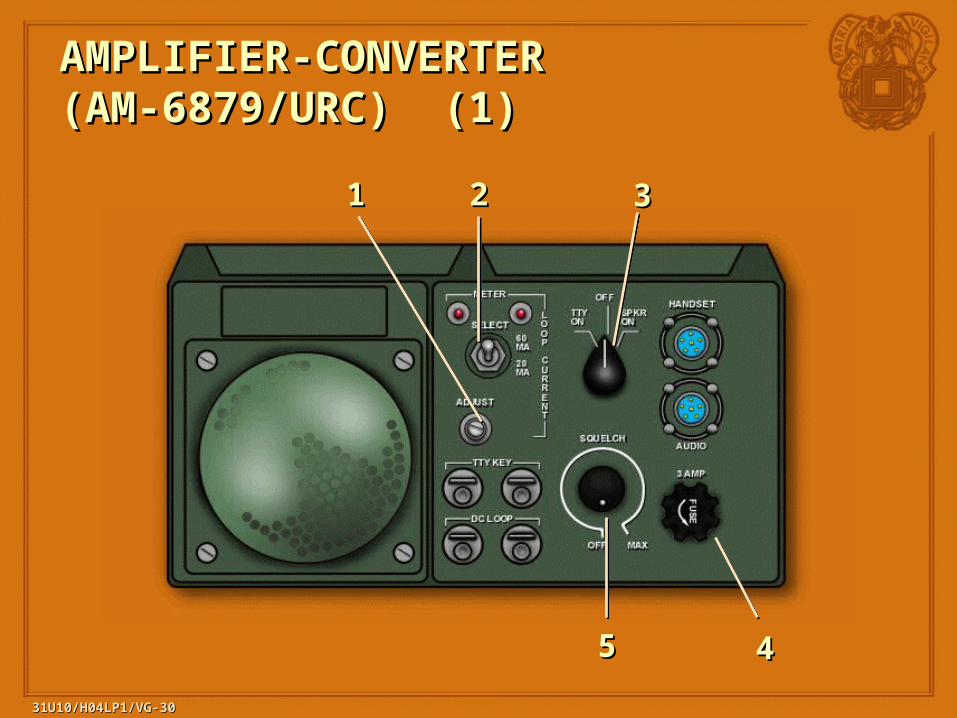
• The Amplifier-Converter Performs Two Main Functions:The Amplifier-Converter Performs Two Main Functions:
- Contains a Frequency-Shift Keying (FSK) - Contains a Frequency-Shift Keying (FSK) Converter That Interfaces Between a Converter That Interfaces Between a 75 Baud Standard Teletypewriter (TTY) 75 Baud Standard Teletypewriter (TTY) and the Audio Circuits of the RT.and the Audio Circuits of the RT.
- Contains an Audio Amplifier and Speaker- Contains an Audio Amplifier and Speaker To Provide Audio Output of Signals Received by To Provide Audio Output of Signals Received by The Radio Set. The Desired Function (SPKR ON The Radio Set. The Desired Function (SPKR ON or TTY ON) Is Selected by a Front Panel Switch.or TTY ON) Is Selected by a Front Panel Switch.
AMPLIFIER-CONVERTER AMPLIFIER-CONVERTER (AM-6879/URC) (2)(AM-6879/URC) (2)

31U10/H04LP1/VG-31U10/H04LP1/VG-3232
RECEIVER-TRANSMITTER (RT-RECEIVER-TRANSMITTER (RT-1209) (1)1209) (1)

31U10/H04LP1/VG-31U10/H04LP1/VG-3333
• The RT Performs the Conversion of Audio Signals The RT Performs the Conversion of Audio Signals To Radio Frequency (RF) and RF to Audio. To Radio Frequency (RF) and RF to Audio.
• The RT Operates As a Standard The RT Operates As a Standard Receiver-Transmitter RT-1209. Receiver-Transmitter RT-1209.
• The RT Control Panel Contains Audio Connectors.The RT Control Panel Contains Audio Connectors.
RECEIVER-TRANSMITTER (RT-RECEIVER-TRANSMITTER (RT-1209) (2)1209) (2)

![N VG [ U{FZJ VG]EJLV[ KLV[P - Gujarat · N VG [ U{FZJ VG]EJLV[ KLV[P - Gujarat ... s], - - - - 5](https://img.pdfslide.us/doc/110x75/5e13200df3ca9032df67634a/n-vg-ufzj-vgejlv-klvp-gujarat-n-vg-ufzj-vgejlv-klvp-gujarat-.jpg)