Embed Size (px)
Citation preview
3.1si31_2001
SI31Advanced Computer
GraphicsAGR
SI31Advanced Computer
GraphicsAGR
Lecture 3Viewing Transformation
Getting Started with OpenGLIntroduction to Projections
3.2si31_2001
Viewing Transformation
3.3si31_2001
The Story So Far...Lecture 2
The Story So Far...Lecture 2
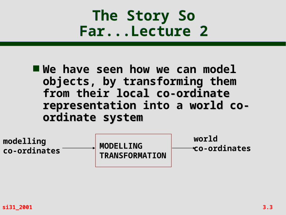
We have seen how we can model objects, by transforming them from their local co-ordinate local co-ordinate representation representation into a world co-world co-ordinate systemordinate system
modellingco-ordinates
worldco-ordinatesMODELLING
TRANSFORMATION
3.4si31_2001
ViewingViewing
Graphics display devices are 2D rectangular screens
Hence we need to understand how to transform our 3D world to a 2D surface
This involves:– selecting the observer position observer position (or
camera position)– selecting the view plane view plane (or camera film
plane)– selecting the type of projectionprojection
3.5si31_2001
Viewing Co-ordinate System - View Reference
Point
Viewing Co-ordinate System - View Reference
Point
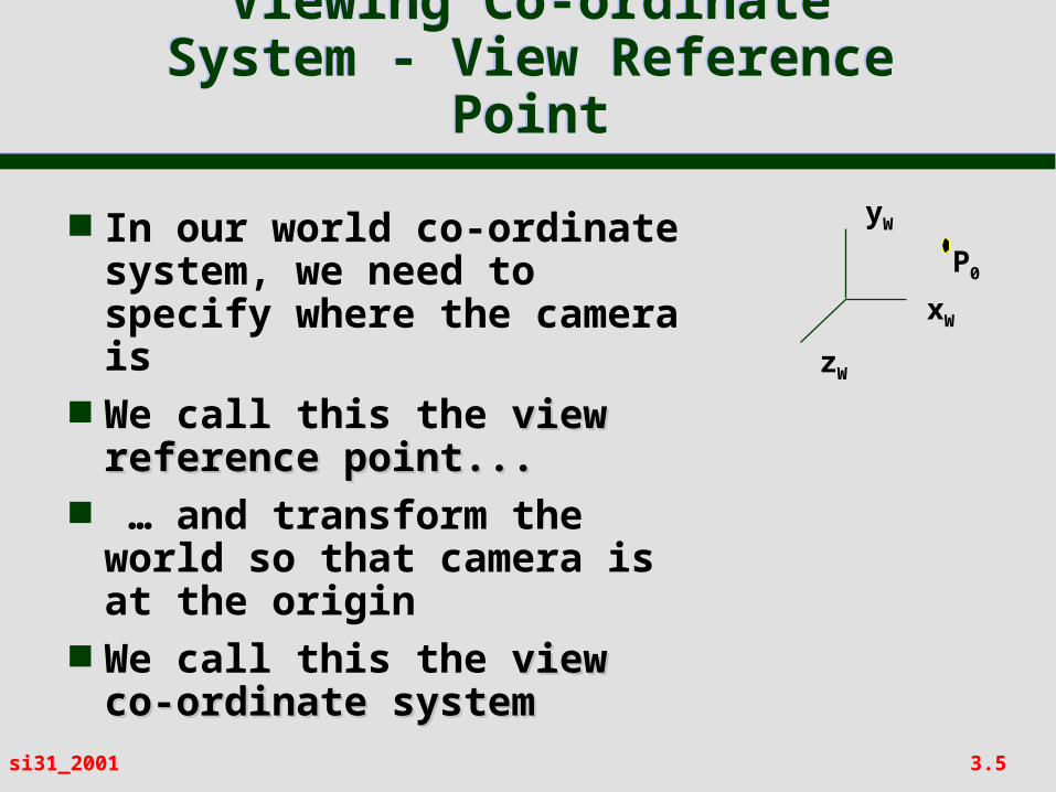
In our world co-ordinate system, we need to specify where the camera is
We call this the view view reference point...reference point...
… and transform the world so that camera is at the origin
We call this the view co- view co-ordinate systemordinate system
xW
yW
zW
P0
3.6si31_2001
Viewing Co-ordinate System - View Plane
Normal
Viewing Co-ordinate System - View Plane
Normal
xW
yW
zW
P0
N
xW
yW
zW
P0
Q
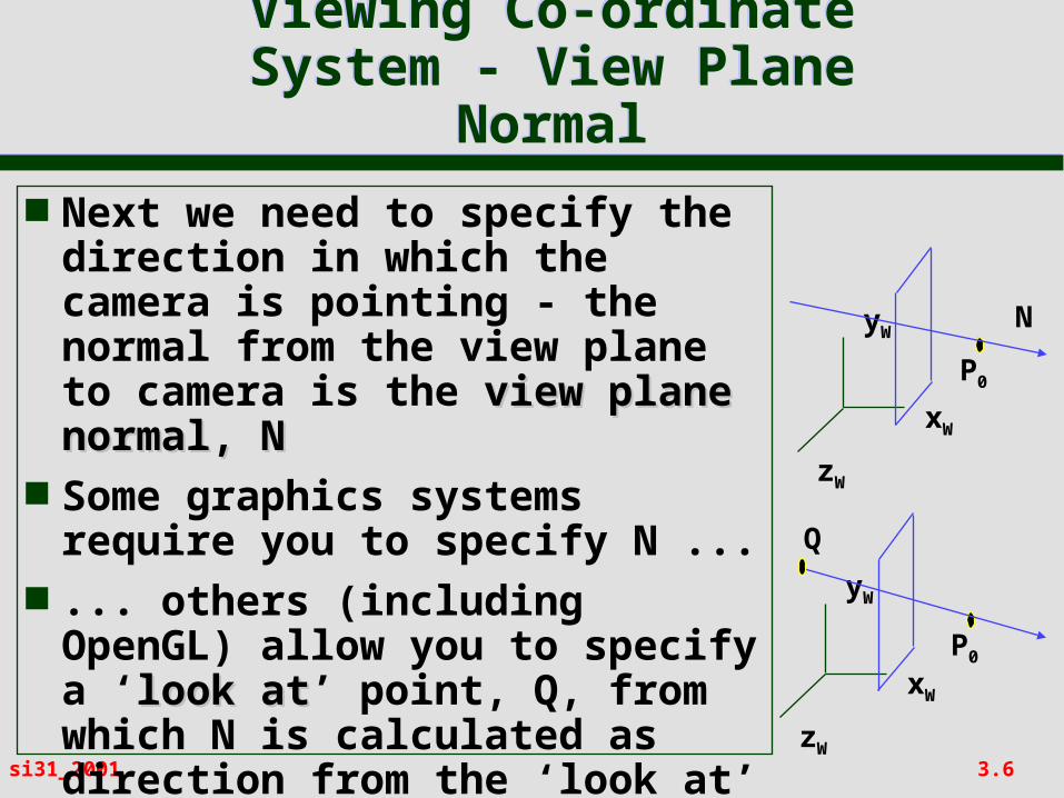
Next we need to specify the direction in which the camera is pointing - the normal from the view plane to camera is the view plane normal, Nview plane normal, N
Some graphics systems require you to specify N ...
... others (including OpenGL) allow you to specify a ‘look look atat’ point, Q, from which N is calculated as direction from the ‘look at’ point to the view reference point
3.7si31_2001
Viewing Co-ordinate System - View Up
Direction
Viewing Co-ordinate System - View Up
Direction
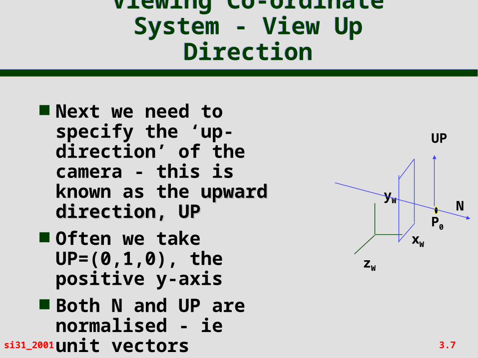
Next we need to specify the ‘up-direction’ of the camera - this is known as the upward upward direction, UPdirection, UP
Often we take UP=(0,1,0), the positive y-axis
Both N and UP are normalised - ie unit vectors
xW
yW
zW
P0
N
UP
3.8si31_2001
Viewing Co-ordinate System
Viewing Co-ordinate System
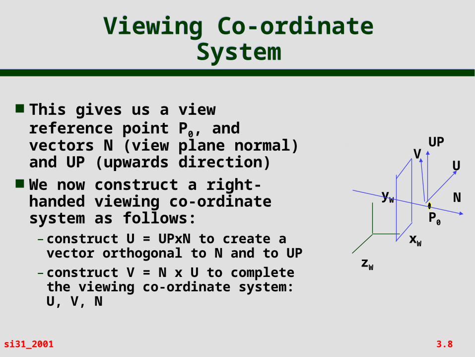
This gives us a view reference point P0, and vectors N (view plane normal) and UP (upwards direction)
We now construct a right-handed viewing co-ordinate system as follows:– construct U = UPxN to create a
vector orthogonal to N and to UP– construct V = N x U to complete
the viewing co-ordinate system: U, V, N
xW
yW
zW
P0
N
UP
U
VV
3.9si31_2001
Interlude: Today’s PuzzleInterlude: Today’s Puzzle
Why does a mirror reflect left-right and not up-down?
3.10si31_2001
Transformation from World to Viewing Co-
ordinates
Transformation from World to Viewing Co-
ordinates
Given an object with positions defined in world co-ordinates, we need to calculate the transformation to viewing co-ordinates
The view reference point must be transformed to the origin, and lines along the U, V, N directions must be transformed to lie along the x, y, z directions
3.11si31_2001
Transformation from World to Viewing Co-
ordinates
Transformation from World to Viewing Co-
ordinates
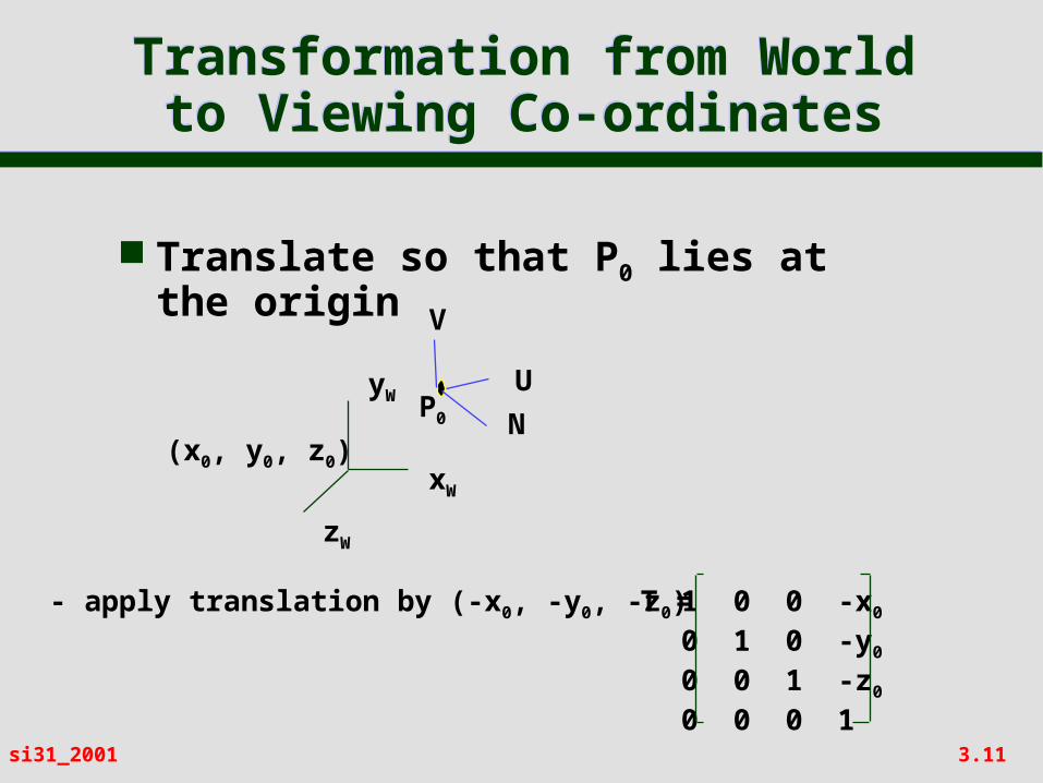
Translate so that P0 lies at the origin
xW
yW
zW
- apply translation by (-x0, -y0, -z0)
(x0, y0, z0)
T = 1 0 0 -x0
0 1 0 -y0
0 0 1 -z0
0 0 0 1
P0
V
U
N
3.12si31_2001
Transformation from World to Viewing Co-
ordinates
Transformation from World to Viewing Co-
ordinates
Apply rotations so that the U, V and N axes are aligned with the xW, yW and zW directions
This involves three rotations Rx, then Ry, then Rz– first rotate around xW to bring N into the
xW-zW plane
– second, rotate around yW to align N with zW
– third, rotate around zW to align V with yW
Composite rotation R = Rz. Ry. Rx
3.13si31_2001
Rotation MatrixRotation Matrix
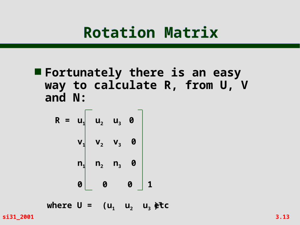
Fortunately there is an easy way to calculate R, from U, V and N:
R = u1 u2 u3 0
v1 v2 v3 0
n1 n2 n3 0
0 0 0 1
where U = (u1 u2 u3 )Tetc
3.14si31_2001
Viewing TransformationViewing Transformation
Thus the viewing transformation is:ViewMatrix = R T
This transforms object positions in world co-ordinates to positions in the viewing co-ordinate system..
.. with camera pointing along negative z-axis at a view plane parallel to x-y plane
We can then apply the projection transformation - to be described later
3.15si31_2001
ExercisesExercises
Convince yourself that the rotation matrix on ‘Rotation Matrix’ slide will have the required effect
Build the view matrix that results from:– camera at (1,2,3)– looking at (3,2,1)– with up direction (0,1,0)

3.16si31_2001
Getting Started with OpenGL
3.17si31_2001
What is OpenGL?What is OpenGL?
OpenGL provides a set of routines (API) for advanced 3D graphics– derived from Silicon Graphics GL– acknowledged industry standard, even on PCs
(OpenGL graphics cards available)– integrates 3D drawing into X (and other
window systems such as Windows NT)– draws simple primitives (points, lines,
polygons) but NOT complex primitives such as spheres
– provides control over transformations, lighting, etc
– Mesa is publically available equivalent
3.18si31_2001
Geometric PrimitivesGeometric Primitives
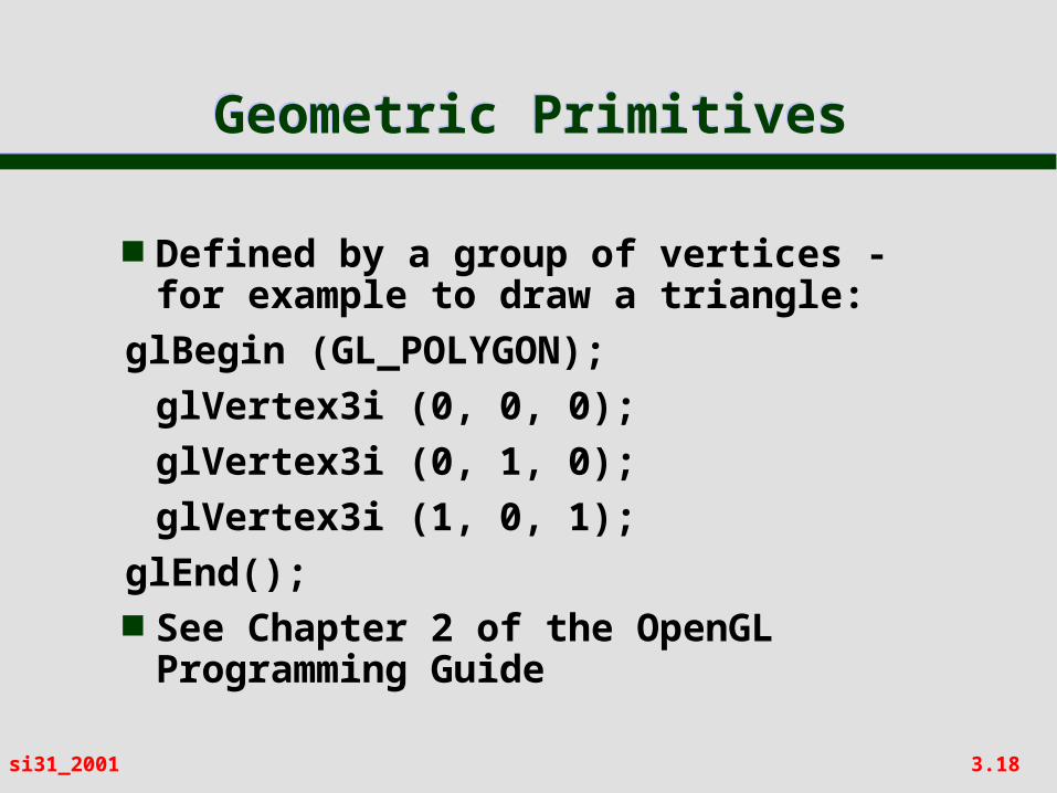
Defined by a group of vertices - for example to draw a triangle:
glBegin (GL_POLYGON);
glVertex3i (0, 0, 0);
glVertex3i (0, 1, 0);
glVertex3i (1, 0, 1);
glEnd(); See Chapter 2 of the OpenGL
Programming Guide
3.19si31_2001
Modelling, Viewing and Projection
Modelling, Viewing and Projection
OpenGL maintains two matrix transformation modes– MODELVIEW
to specify modelling transformations, and transformations to align camera
– PROJECTION
to specify the type of projection (parallel or perspective) and clipping planes
See Chapter 3 of OpenGL Programming Guide
3.20si31_2001
ModellingModelling
For modelling… set the matrix mode, and create the transformation...
Thus to set a scaling on each axis...glMatrixMode(GL_MODELVIEW);
glLoadIdentity();
glScaled(sx,sy,sz);
3.21si31_2001
ViewingViewing
For viewing, use gluLookAt()to create a view transformation matrixgluLookAt(eyex,eyey,eyez, lookx,looky,lookz, upx,upy,upz)
ThusglMatrixMode(GL_MODELVIEW);
glLoadIdentity();
glScaled(sx,sy,sz);
gluLookAt(eyex,eyey,eyez, lookx,looky,lookz, upx,upy,upz);
creates a model-view matrix

3.22si31_2001
OpenGL Utility Library (GLU)
OpenGL Utility Toolkit (GLUT)
OpenGL Utility Library (GLU)
OpenGL Utility Toolkit (GLUT)
GLU:– useful set of utility routines written in terms
of OpenGL … such as gluLookAt() GLUT (Appendix D of OpenGL Guide):
– Set of routines to provide an interface to the underlying windowing system - plus many useful high-level primitives (even a teapot - glutSolidTeapot()!)
– Allows you to write ‘event driven’ applications– you specify call back functions which are
executed when an event (eg window resize) occurs
3.23si31_2001
How to Get StartedHow to Get Started
Look at the SI31/AGR resources page:– http://www.comp.leeds.ac.uk/kwb/
si31/ resources.html Points you to:
– example programs– information about GLUT– information about OpenGL– information about Mesa 3D– a simple exercise
3.24si31_2001
Introduction to Projections
3.25si31_2001
Viewing Pipeline So FarViewing Pipeline So Far
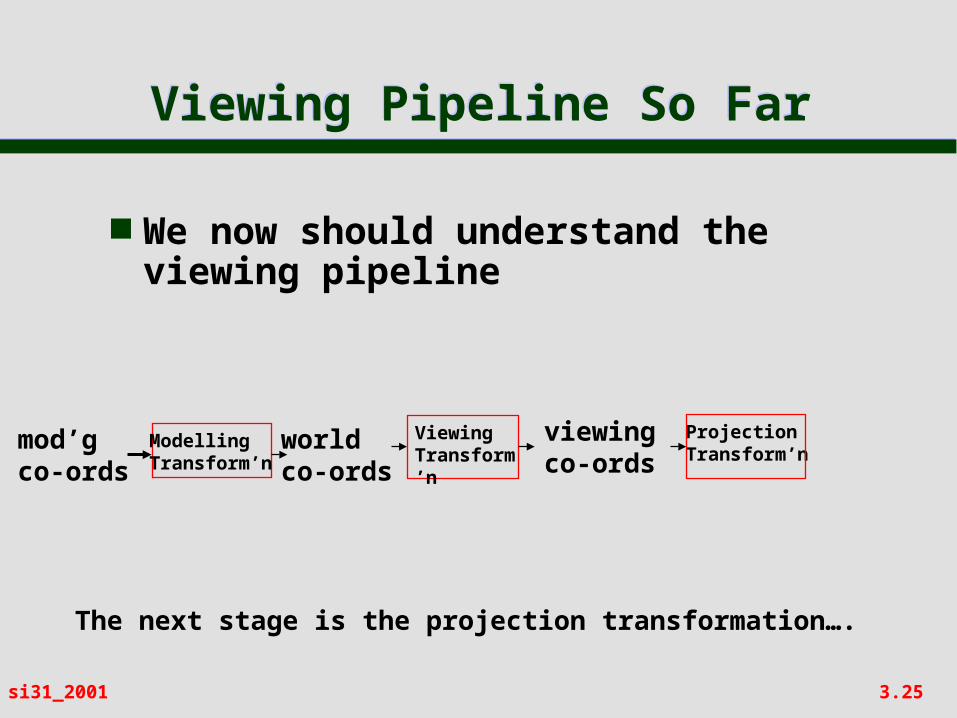
We now should understand the viewing pipeline
mod’gco-ords
worldco-ords
viewingco-ords
ModellingTransform’n
ViewingTransform’n
The next stage is the projection transformation….
ProjectionTransform’n
3.26si31_2001
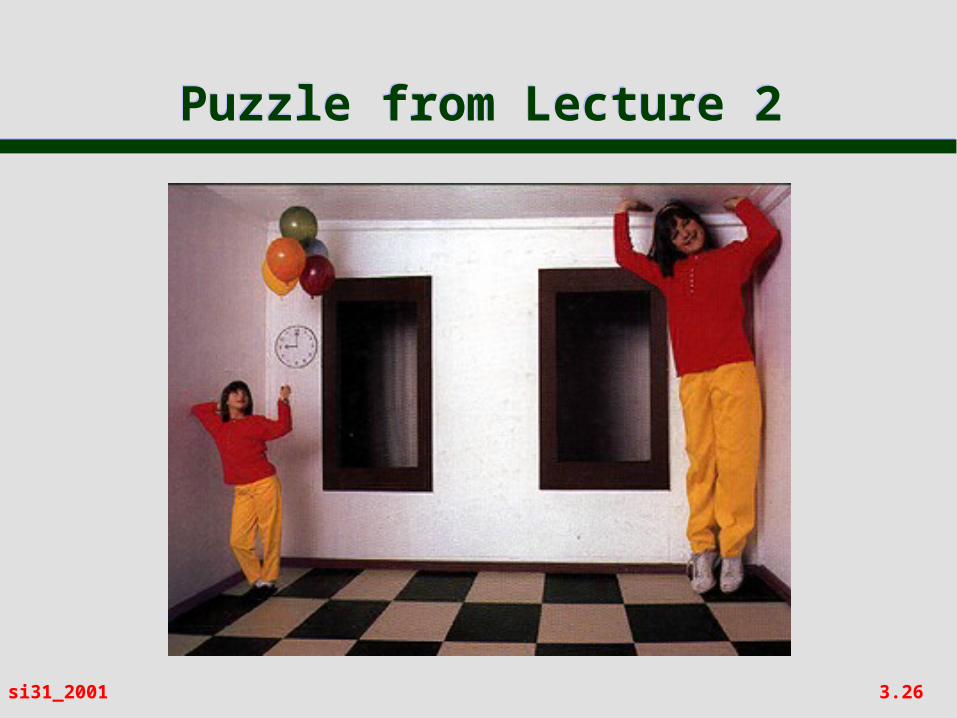
Puzzle from Lecture 2Puzzle from Lecture 2
3.27si31_2001
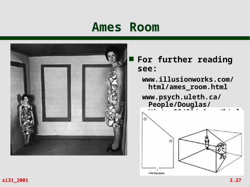
Ames RoomAmes Room
For further reading see:www.illusionworks.com/
html/ames_room.html
www.psych.uleth.ca/People/Douglas/Winter99/01/ Ames.html
3.28si31_2001
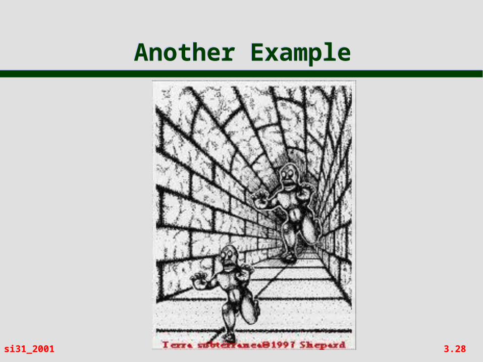
Another ExampleAnother Example
3.29si31_2001
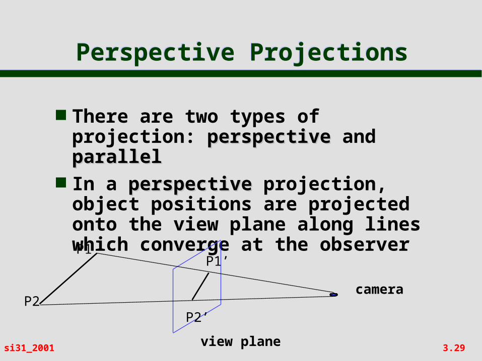
Perspective ProjectionsPerspective Projections
There are two types of projection: perspectiveperspective and parallelparallel
In a perspectiveperspective projection, object positions are projected onto the view plane along lines which converge at the observerP1
P2
P1’
P2’
view plane
camera
3.30si31_2001
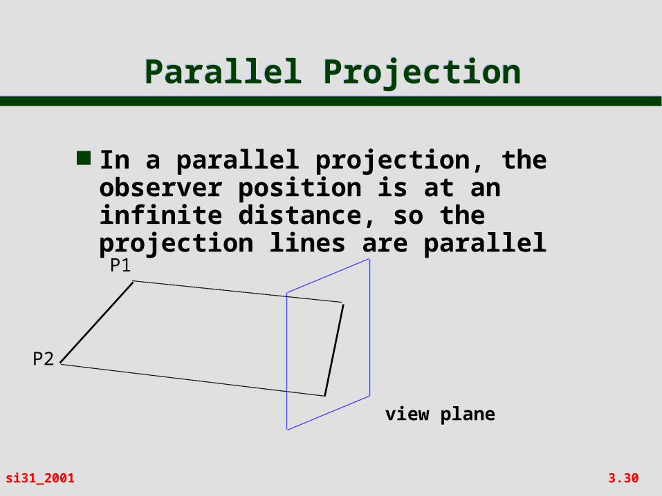
Parallel ProjectionParallel Projection
In a parallel projection, the observer position is at an infinite distance, so the projection lines are parallelP1
P2
view plane
3.31si31_2001
Perspective and Parallel Projection
Perspective and Parallel Projection
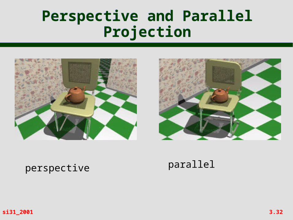
Parallel projection preserves the relative proportions of objects, but does not give a realistic view
Perspective projection gives realistic views, but does not preserve proportions– Projections of distant objects are
smaller than projections of objects of the same size which are closer to the view plane
3.32si31_2001
Perspective and Parallel Projection
Perspective and Parallel Projection
perspective parallel