Embed Size (px)
Citation preview
1
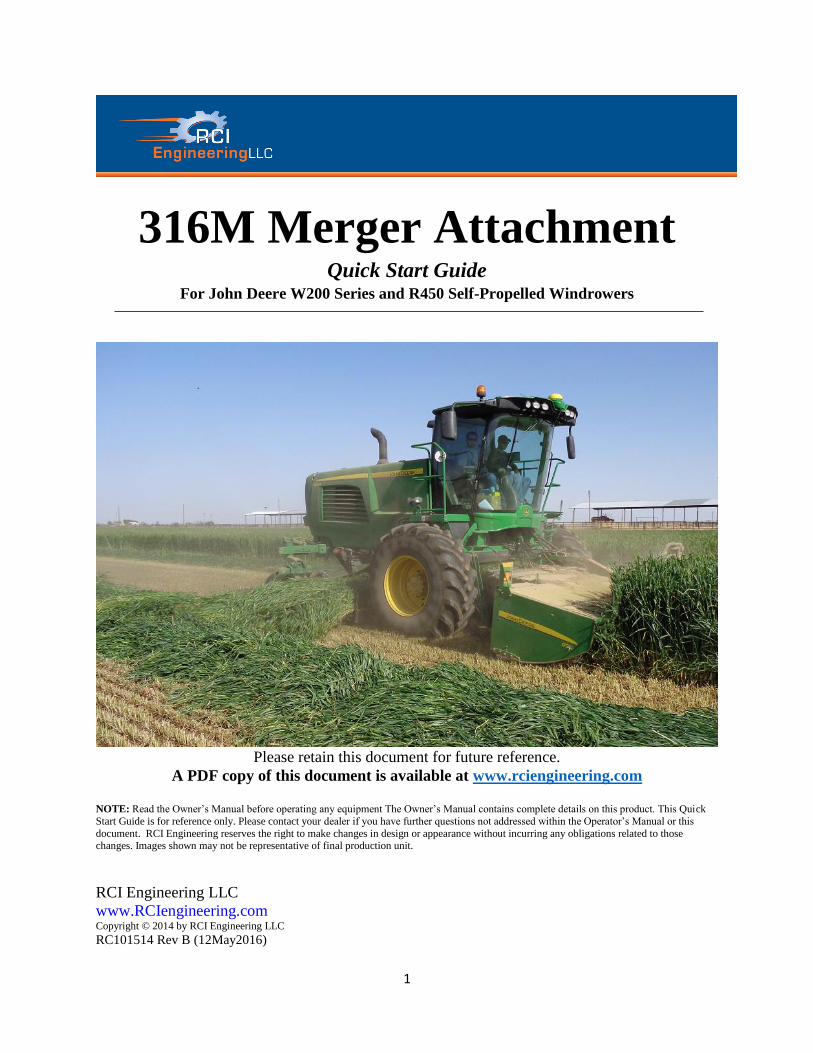
316M Merger Attachment Quick Start Guide
For John Deere W200 Series and R450 Self-Propelled Windrowers
Please retain this document for future reference.
A PDF copy of this document is available at www.rciengineering.com
NOTE: Read the Owner’s Manual before operating any equipment The Owner’s Manual contains complete details on this product. This Quick
Start Guide is for reference only. Please contact your dealer if you have further questions not addressed within the Operator’s Manual or this
document. RCI Engineering reserves the right to make changes in design or appearance without incurring any obligations related to those changes. Images shown may not be representative of final production unit.
RCI Engineering LLC
www.RCIengineering.com Copyright © 2014 by RCI Engineering LLC
RC101514 Rev B (12May2016)
2
Operating the Attachment
W200-Series Self-Propelled Windrower
Refer to the W200 Self-Propelled
Windrower Operator Manual for operation
of controls of Windrower.
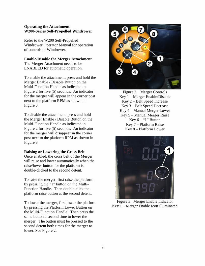
Enable/Disable the Merger Attachment
The Merger Attachment needs to be
ENABLED for automatic operation.
To enable the attachment, press and hold the
Merger Enable / Disable Button on the
Multi-Function Handle as indicated in
Figure 2 for five (5) seconds. An indicator
for the merger will appear in the corner post
next to the platform RPM as shown in
Figure 3.
To disable the attachment, press and hold
the Merger Enable / Disable Button on the
Multi-Function Handle as indicated in
Figure 2 for five (5) seconds. An indicator
for the merger will disappear in the corner
post next to the platform RPM as shown in
Figure 3.
Raising or Lowering the Cross Belt
Once enabled, the cross belt of the Merger
will raise and lower automatically when the
raise/lower button for the platform is
double-clicked to the second detent.
To raise the merger, first raise the platform
by pressing the “1” button on the Multi-
Function Handle. Then double-click the
platform raise button at the second detent.
To lower the merger, first lower the platform
by pressing the Platform Lower Button on
the Multi-Function Handle. Then press the
same button a second time to lower the
merger. The button must be pressed to the
second detent both times for the merger to
lower. See Figure 2.
Figure 2. Merger Controls
Key 1 – Merger Enable/Disable
Key 2 – Belt Speed Increase
Key 3 – Belt Speed Decrease
Key 4 – Manual Merger Lower
Key 5 – Manual Merger Raise
Key 6 – “1” Button
Key 7 – Platform Raise
Key 8 – Platform Lower
Figure 3. Merger Enable Indicator
Key 1 – Merger Enable Icon Illuminated
3
Manual Raise/Lower of Cross Belt
When the Merger is enabled, the cross belt
can be raised and/or lowered manually.
First, enable the Merger Adjustment Mode.
IMPORTANT: Merger Adjustment Mode
will lock out any platform adjustments from
the Multi-Function Handle for five (5)
seconds after the last adjustment is made.
The unit will revert back to platform
adjustment automatically after five (5)
seconds of no adjustments.
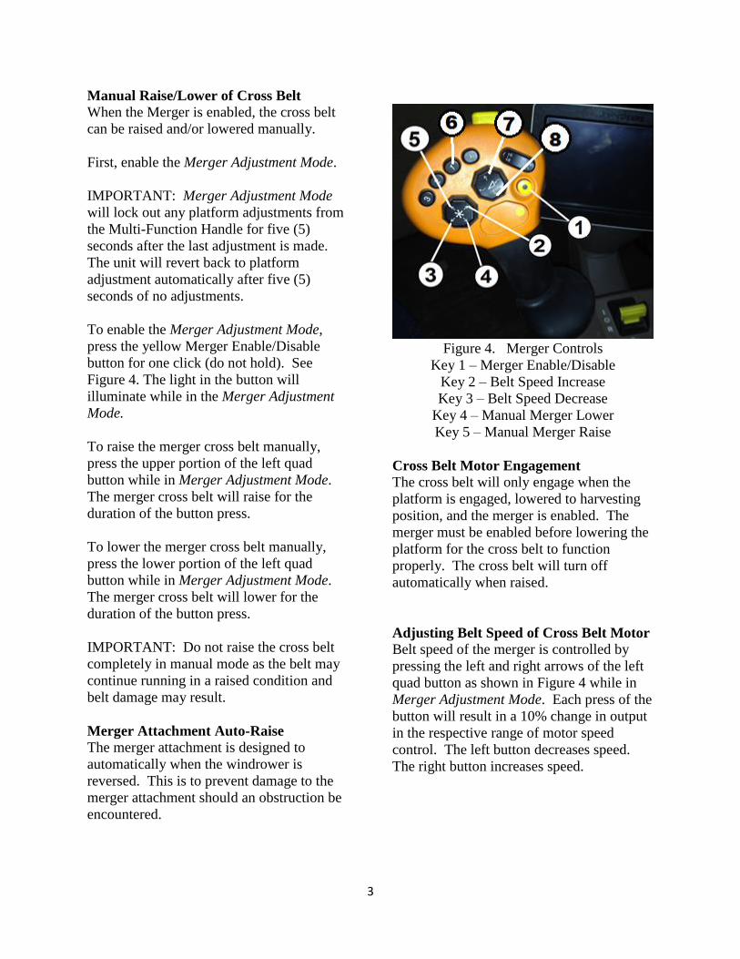
To enable the Merger Adjustment Mode,
press the yellow Merger Enable/Disable
button for one click (do not hold). See
Figure 4. The light in the button will
illuminate while in the Merger Adjustment
Mode.
To raise the merger cross belt manually,
press the upper portion of the left quad
button while in Merger Adjustment Mode.
The merger cross belt will raise for the
duration of the button press.
To lower the merger cross belt manually,
press the lower portion of the left quad
button while in Merger Adjustment Mode.
The merger cross belt will lower for the
duration of the button press.
IMPORTANT: Do not raise the cross belt
completely in manual mode as the belt may
continue running in a raised condition and
belt damage may result.
Merger Attachment Auto-Raise
The merger attachment is designed to
automatically when the windrower is
reversed. This is to prevent damage to the
merger attachment should an obstruction be
encountered.
Figure 4. Merger Controls
Key 1 – Merger Enable/Disable
Key 2 – Belt Speed Increase
Key 3 – Belt Speed Decrease
Key 4 – Manual Merger Lower
Key 5 – Manual Merger Raise
Cross Belt Motor Engagement
The cross belt will only engage when the
platform is engaged, lowered to harvesting
position, and the merger is enabled. The
merger must be enabled before lowering the
platform for the cross belt to function
properly. The cross belt will turn off
automatically when raised.
Adjusting Belt Speed of Cross Belt Motor
Belt speed of the merger is controlled by
pressing the left and right arrows of the left
quad button as shown in Figure 4 while in
Merger Adjustment Mode. Each press of the
button will result in a 10% change in output
in the respective range of motor speed
control. The left button decreases speed.
The right button increases speed.
4
Front Belt Motor Engagement
Front Belt motor engagement is
automatically acquired by engaging the
platform of the machine. To disengage, turn
off the platform.
Note: The front belt motor speed will
remain constant at 900 to 950 rpm. It is not
adjustable for normal operation.
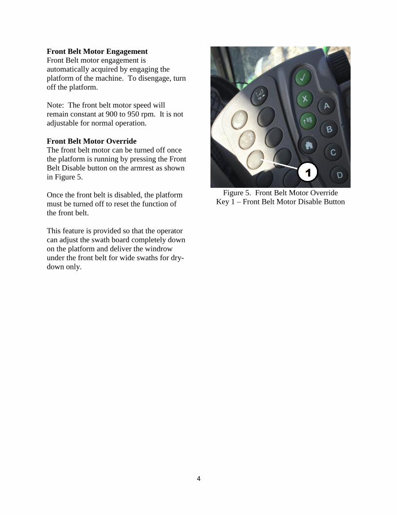
Front Belt Motor Override
The front belt motor can be turned off once
the platform is running by pressing the Front
Belt Disable button on the armrest as shown
in Figure 5.
Once the front belt is disabled, the platform
must be turned off to reset the function of
the front belt.
This feature is provided so that the operator
can adjust the swath board completely down
on the platform and deliver the windrow
under the front belt for wide swaths for dry-
down only.
Figure 5. Front Belt Motor Override
Key 1 – Front Belt Motor Disable Button

5
Operating the Attachment
R450 Self-Propelled Windrower
Enable/Disable the Merger Attachment
Refer to the R450 Self-Propelled Windrower
Operator’s Manual for operation of controls
of Windrower.
The Merger Attachment needs to be
ENABLED for automatic operation.
To enable the attachment, press the Merger
Enable / Disable Control on the Multi-
Function Handle as indicated in Figure 6.
An icon will appear in the top view of the
corner post to indicate when the Merger is
enabled.
The vertical bars with an angled belt as
shown by Key 1, Figure 7, indicate that the
Merger Option is installed on the machine.
When enabled, arrows are displayed as
shown by Key 2, Figure 7, indicating that
the Merger is active.
When activated, the Merger will deliver the
windrow automatically to the side of the
R450. The cross belt will raise and lower
automatically when the platform is raised
and lowered.
To disable the Merger, simply press the
Disable Control on the Hydrostatic Control
Handle, Key 3, Figure 6. This will raise the
unit to transport position, disable the cross
belt from turning, and turn off the Merger
Enabled Icon in the Upper Cornerpost
Display.
.
Figure 6. Hydrostatic Control Handle
Key 1 – Directional Control
Key 2 – Deflector Control
Key 3 – Merger Enable / Disable Control
Figure 7. Upper Cornerpost Display
Key 1 – Merger Installed
Key 2 – Merger Enabled
6
Raising or Lowering the Cross Belt
(R450)
The belt frame lift mechanism uses a
hydraulic cylinder independent of the
platform lift circuit and is designed to
automatically raise and lower at the same
time as the platform.
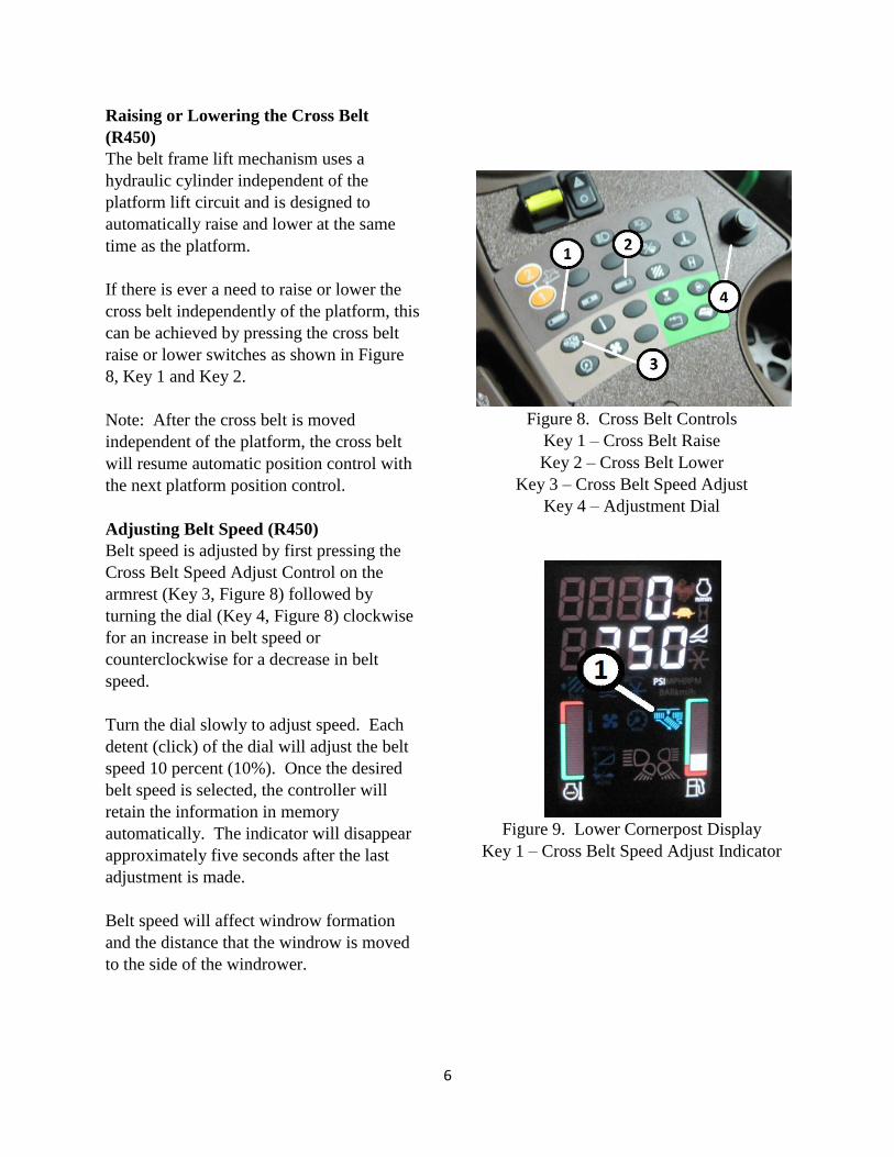
If there is ever a need to raise or lower the
cross belt independently of the platform, this
can be achieved by pressing the cross belt
raise or lower switches as shown in Figure
8, Key 1 and Key 2.
Note: After the cross belt is moved
independent of the platform, the cross belt
will resume automatic position control with
the next platform position control.
Adjusting Belt Speed (R450)
Belt speed is adjusted by first pressing the
Cross Belt Speed Adjust Control on the
armrest (Key 3, Figure 8) followed by
turning the dial (Key 4, Figure 8) clockwise
for an increase in belt speed or
counterclockwise for a decrease in belt
speed.
Turn the dial slowly to adjust speed. Each
detent (click) of the dial will adjust the belt
speed 10 percent (10%). Once the desired
belt speed is selected, the controller will
retain the information in memory
automatically. The indicator will disappear
approximately five seconds after the last
adjustment is made.
Belt speed will affect windrow formation
and the distance that the windrow is moved
to the side of the windrower.
Figure 8. Cross Belt Controls
Key 1 – Cross Belt Raise
Key 2 – Cross Belt Lower
Key 3 – Cross Belt Speed Adjust
Key 4 – Adjustment Dial
Figure 9. Lower Cornerpost Display
Key 1 – Cross Belt Speed Adjust Indicator
7
ADJUSTMENTS
Front Belt Tension Adjustment
The belt tension for the front belt is
maintained by a set of springs on the idler
roller of the belt frame assembly. These
springs are used to apply a specific amount
of load on the belt for proper tensioning.
First, always inspect the rollers to make sure
they are clean of debris. Clean as necessary.
IMPORTANT: The three M12 Lock nuts
that retain the bearing carrier to the belt
frame must be tightened such that the
washer under the lock nut can freely turn
and the bolt head is completely engaged in
the slot (approximately 10 lbf-ft (14 N-m)).
Over-tightening will not allow the bearing
carrier to slide in the slots of the belt frame,
which will lead to improper adjustment of
belt tension. Do not tighten the bolts further
after the belt tension adjustment is made as
the bearing carrier must be able to slide
along the frame as the belt stretches over
time.
Note: Failure to maintain proper belt tension
may result in poor belt performance, belt
slippage, and overall shortened belt service
life.
Important: Once tensioned, only relieve the
belt tension for service work. Do not relieve
the belt tension when the merger is not in
use (i.e. in the off-season). Releasing belt
tension and then re-tensioning may cause
belt reliability issues.
Follow the steps below to adjust belt
tension. Begin at the side of the belt frame.
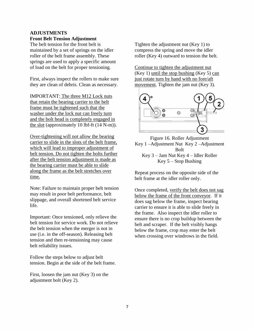
First, loosen the jam nut (Key 3) on the
adjustment bolt (Key 2).
Tighten the adjustment nut (Key 1) to
compress the spring and move the idler
roller (Key 4) outward to tension the belt.
Continue to tighten the adjustment nut
(Key 1) until the stop bushing (Key 5) can
just rotate turn by hand with no fore/aft
movement. Tighten the jam nut (Key 3).
Figure 16. Roller Adjustment
Key 1 –Adjustment Nut Key 2 –Adjustment
Bolt
Key 3 – Jam Nut Key 4 – Idler Roller
Key 5 – Stop Bushing
Repeat process on the opposite side of the
belt frame at the idler roller only.
Once completed, verify the belt does not sag
below the frame of the front conveyor. If it
does sag below the frame, inspect bearing
carrier to ensure it is able to slide freely in
the frame. Also inspect the idler roller to
ensure there is no crop buildup between the
belt and scraper. If the belt visibly hangs
below the frame, crop may enter the belt
when crossing over windrows in the field.
8
Cross Belt Tension Adjustment
The belt tension for the cross belt is
maintained by a set of springs on the idler
roller of the belt frame assembly. These
springs are used to apply a specific amount
of load on the belt for proper tensioning.
First, always inspect the rollers to make sure
they are clear of debris. Clean as necessary.
The drive roller should always be verified
first to determine the position of the belt.
The objective of the adjustment is to adjust
the motor end of the drive roller out by ¼”
relative to the opposite end of the drive
roller and the frame. This results in the
drive roller setting on a slight angle to
control the belt position under load. The
drive roller is only typically moved when a
belt is changed or to service other
components of the unit and is not moved to
adjust the tension of the belt.
The angle of the drive roller determines the
angle of tracking of the belt. It must be
angled slightly so that the belt angle
counteracts the impact of gravity (sag) on
the belt.
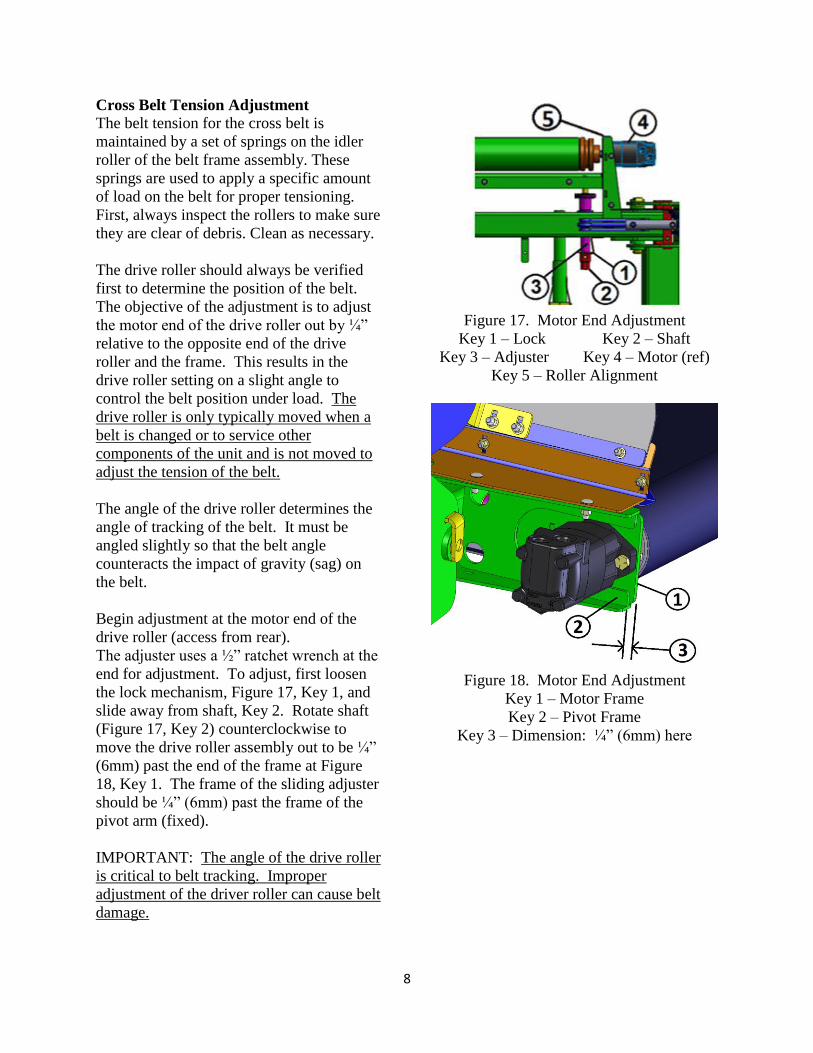
Begin adjustment at the motor end of the
drive roller (access from rear).
The adjuster uses a ½” ratchet wrench at the
end for adjustment. To adjust, first loosen
the lock mechanism, Figure 17, Key 1, and
slide away from shaft, Key 2. Rotate shaft
(Figure 17, Key 2) counterclockwise to
move the drive roller assembly out to be ¼”
(6mm) past the end of the frame at Figure
18, Key 1. The frame of the sliding adjuster
should be ¼” (6mm) past the frame of the
pivot arm (fixed).
IMPORTANT: The angle of the drive roller
is critical to belt tracking. Improper
adjustment of the driver roller can cause belt
damage.
Figure 17. Motor End Adjustment
Key 1 – Lock Key 2 – Shaft
Key 3 – Adjuster Key 4 – Motor (ref)
Key 5 – Roller Alignment
Figure 18. Motor End Adjustment
Key 1 – Motor Frame
Key 2 – Pivot Frame
Key 3 – Dimension: ¼” (6mm) here
9
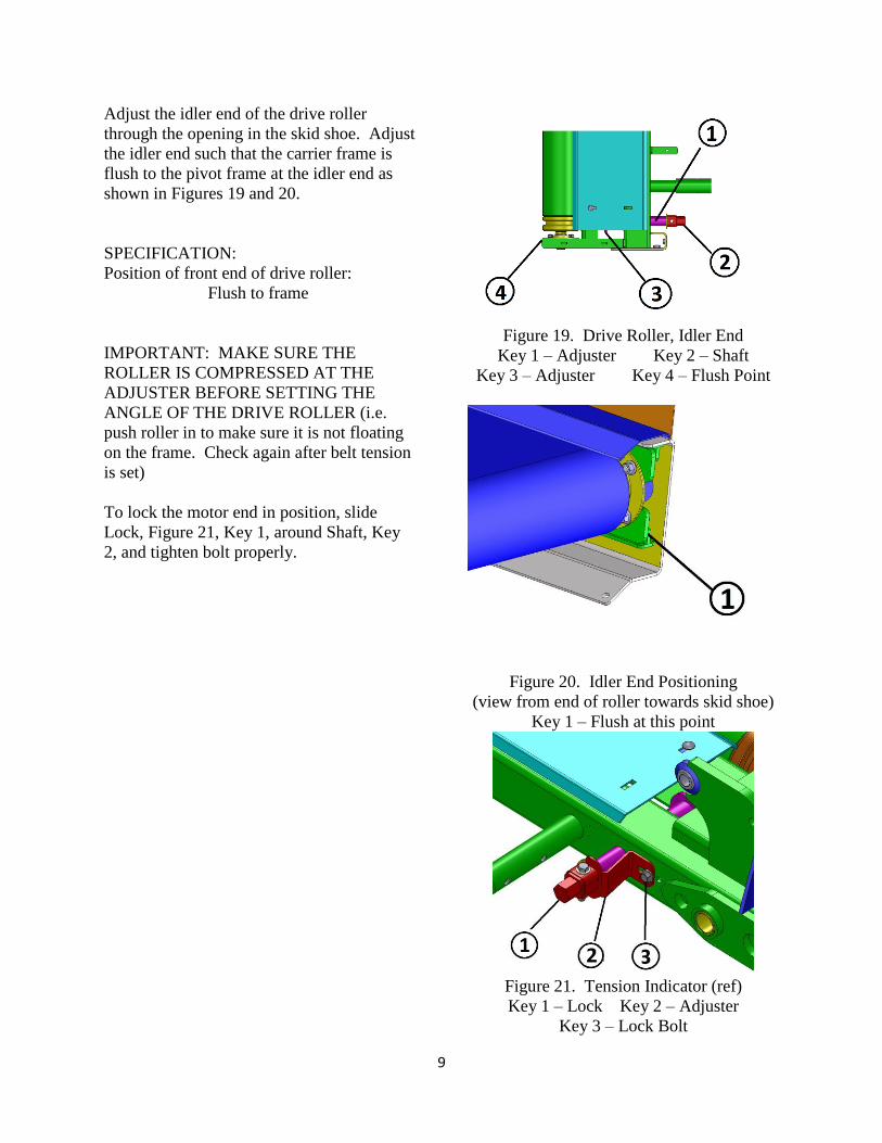
Adjust the idler end of the drive roller
through the opening in the skid shoe. Adjust
the idler end such that the carrier frame is
flush to the pivot frame at the idler end as
shown in Figures 19 and 20.
SPECIFICATION:
Position of front end of drive roller:
Flush to frame
IMPORTANT: MAKE SURE THE
ROLLER IS COMPRESSED AT THE
ADJUSTER BEFORE SETTING THE
ANGLE OF THE DRIVE ROLLER (i.e.
push roller in to make sure it is not floating
on the frame. Check again after belt tension
is set)
To lock the motor end in position, slide
Lock, Figure 21, Key 1, around Shaft, Key
2, and tighten bolt properly.
Figure 19. Drive Roller, Idler End
Key 1 – Adjuster Key 2 – Shaft
Key 3 – Adjuster Key 4 – Flush Point
Figure 20. Idler End Positioning
(view from end of roller towards skid shoe)
Key 1 – Flush at this point
Figure 21. Tension Indicator (ref)
Key 1 – Lock Key 2 – Adjuster
Key 3 – Lock Bolt
10
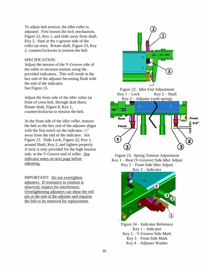
To adjust belt tension, the idler roller is
adjusted. First loosen the lock mechanism,
Figure 22, Key 1, and slide away from shaft,
Key 2. Start at the v-groove side of the
roller (at rear). Rotate shaft, Figure 23, Key
2, counterclockwise to tension the belt.
SPECIFICATION:
Adjust the tension of the V-Groove side of
the roller to increase tension using the
provided indicators. This will result in the
hex end of the adjuster becoming flush with
the end of the indicator.
See Figure 23.
Adjust the front side of the idler roller (at
front of cross belt, through skid shoe).
Rotate shaft, Figure 8, Key 1,
counterclockwise to tension the belt.
At the front side of the idler roller, tension
the belt so the hex end of the adjuster aligns
with the first notch on the indicator, ½”
away from the end of the indicator. See
Figure 23. Slide Lock, Figure 22, Key 1,
around Shaft, Key 2, and tighten properly.
A lock is only provided for the high tension
side, at the V-Groove end of roller. See
indicator notes on next page before
adjusting.
IMPORTANT: Do not overtighten
adjusters. If resistance to rotation is
observed, inspect for interference.
Overtightening adjusters can shear the roll
pin at the end of the adjuster and requires
the belt to be removed for replacement.
Figure 22. Idler End Adjustment
Key 1 – Lock Key 2 – Shaft
Key 3 – Adjuster (with spring)
Figure 23. Spring Tension Adjustment
Key 1 – Rear (V-Groove) Side Idler Adjust
Key 2 – Front Side Idler Adjust
Key 3 – Indicator
.
Figure 24 – Indicator Reference
Key 1 – Indicator
Key 2 – V-Groove Side Mark
Key 3 – Front Side Mark
Key 4 – Adjuster Washer
11
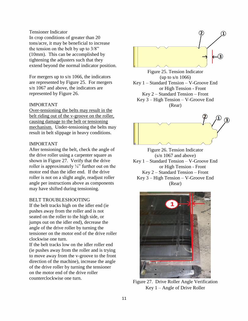
Tensioner Indicator
In crop conditions of greater than 20
tons/acre, it may be beneficial to increase
the tension on the belt by up to 3/8”
(10mm). This can be accomplished by
tightening the adjusters such that they
extend beyond the normal indicator position.
For mergers up to s/n 1066, the indicators
are represented by Figure 25. For mergers
s/n 1067 and above, the indicators are
represented by Figure 26.
IMPORTANT
Over-tensioning the belts may result in the
belt riding out of the v-groove on the roller,
causing damage to the belt or tensioning
mechanism. Under-tensioning the belts may
result in belt slippage in heavy conditions.
IMPORTANT
After tensioning the belt, check the angle of
the drive roller using a carpenter square as
shown in Figure 27. Verify that the drive
roller is approximately ¼” further out on the
motor end than the idler end. If the drive
roller is not on a slight angle, readjust roller
angle per instructions above as components
may have shifted during tensioning.
BELT TROUBLESHOOTING
If the belt tracks high on the idler end (ie
pushes away from the roller and is not
seated on the roller to the high side, or
jumps out on the idler end), decrease the
angle of the drive roller by turning the
tensioner on the motor end of the drive roller
clockwise one turn.
If the belt tracks low on the idler roller end
(ie pushes away from the roller and is trying
to move away from the v-groove to the front
direction of the machine), increase the angle
of the drive roller by turning the tensioner
on the motor end of the drive roller
counterclockwise one turn.
Figure 25. Tension Indicator
(up to s/n 1066)
Key 1 – Standard Tension – V-Groove End
or High Tension - Front
Key 2 – Standard Tension – Front
Key 3 – High Tension – V-Groove End
(Rear)
Figure 26. Tension Indicator
(s/n 1067 and above)
Key 1 – Standard Tension – V-Groove End
or High Tension - Front
Key 2 – Standard Tension – Front
Key 3 – High Tension – V-Groove End
(Rear)
Figure 27. Drive Roller Angle Verification
Key 1 – Angle of Drive Roller
12
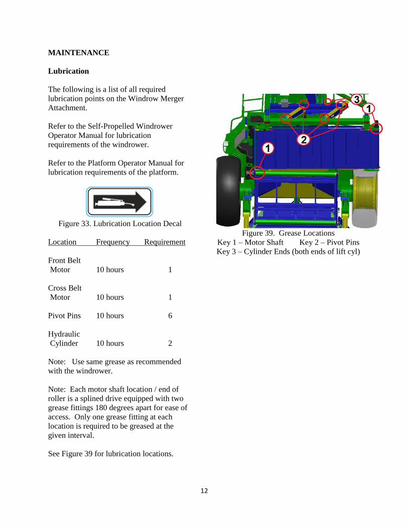
MAINTENANCE
Lubrication
The following is a list of all required
lubrication points on the Windrow Merger
Attachment.
Refer to the Self-Propelled Windrower
Operator Manual for lubrication
requirements of the windrower.
Refer to the Platform Operator Manual for
lubrication requirements of the platform.
Figure 33. Lubrication Location Decal
Location Frequency Requirement
Front Belt
Motor 10 hours 1
Cross Belt
Motor 10 hours 1
Pivot Pins 10 hours 6
Hydraulic
Cylinder 10 hours 2
Note: Use same grease as recommended
with the windrower.
Note: Each motor shaft location / end of
roller is a splined drive equipped with two
grease fittings 180 degrees apart for ease of
access. Only one grease fitting at each
location is required to be greased at the
given interval.
See Figure 39 for lubrication locations.
Figure 39. Grease Locations
Key 1 – Motor Shaft Key 2 – Pivot Pins
Key 3 – Cylinder Ends (both ends of lift cyl)

13


![MRL Lift GearLess Belt Green Lift - · PDF fileSafety gear releasing Ecology ... Output power [kW] 1 1 2 opposite 2 opposite 1 2 opposite 1 2 opposite Entrances [No.] 1000 1000 13](https://img.pdfslide.us/doc/110x75/5aad805d7f8b9a693f8e7982/mrl-lift-gearless-belt-green-lift-gear-releasing-ecology-output-power-kw.jpg)