Embed Size (px)
Citation preview

XTR™ 5 and XTR™ 7 Airless Spray GunInstructions/PartsSee page 9 for model numbers.Maximum Working Pressure:
XTR 5: 5000 psi (35 MPa, 345 bar)XTR 7: 7250 psi (50 MPa, 500 bar)
For use with protective coating materials
312145D
The following warnings are for the setup, use, grounding, maintenance, and repair of this equip-ment. The exclamation point symbol alerts you to a general warning and the hazard symbols refer to procedure-specific risks. Refer back to these warnings. Additional product-specific warnings may be found throughout the body of this manual where applicable.
WARNINGSKIN INJECTION HAZARD High-pressure fluid from gun, hose leaks, or ruptured components will pierce skin. This may look like just a cut, but it is a serious injury that can result in amputation. Get immediate surgical treatment.• Do not point gun at anyone or at any part of the body.• Do not put your hand over the spray tip.• Do not stop or deflect leaks with your hand, body, glove, or rag.• Do not spray without tip guard and trigger guard installed.• Engage trigger lock when not spraying.• Follow Pressure Relief Procedure in this manual, when you stop spraying and
before cleaning, checking, or servicing equipment.
PRESSURIZED EQUIPMENT HAZARD Fluid from the gun/dispense valve, leaks, or ruptured components can splash in the eyes or on skin and cause serious injury.• Follow Pressure Relief Procedure in this manual, when you stop spraying and
before cleaning, checking, or servicing equipment. • Tighten all fluid connections before operating the equipment.• Check hoses, tubes, and couplings daily. Replace worn or damaged parts immedi-
ately.
IMPORTANT SAFETY INSTRUCTIONS.Refer to your sprayer instruction manual for pressure relief, priming, and spraying instructions. Keep these instructions. ti5045b
II 2 G c T6

WARNING
2 312145D
FIRE AND EXPLOSION HAZARD Flammable fumes, such as solvent and paint fumes, in work area can ignite or explode. To help prevent fire and explosion:• Use equipment only in well ventilated area.• Eliminate all ignition sources; such as pilot lights, cigarettes, portable electric
lamps, and plastic drop cloths (potential static arc). • Keep work area free of debris, including solvent, rags and gasoline.• Do not plug or unplug power cords or turn power or light switches on or off when
flammable fumes are present.• Ground all equipment in the work area. See Grounding instructions.• Use only grounded hoses.• Hold gun firmly to side of grounded pail when triggering into pail.• If there is static sparking or you feel a shock, stop operation immediately. Do not
use equipment until you identify and correct the problem.• Keep a working fire extinguisher in the work area.
EQUIPMENT MISUSE HAZARD Misuse can cause death or serious injury.• Do not operate the unit when fatigued or under the influence of drugs or alcohol.• Do not exceed the maximum working pressure or temperature rating of the lowest
rated system component. See Technical Data in all equipment manuals.• Use fluids and solvents that are compatible with equipment wetted parts. See
Technical Data in all equipment manuals. Read fluid and solvent manufacturer’s warnings. For complete information about your material, request MSDS forms from distributor or retailer.
• Check equipment daily. Repair or replace worn or damaged parts immediately with genuine manufacturer’s replacement parts only.
• Do not alter or modify equipment.• Use equipment only for its intended purpose. Call your distributor for information.• Route hoses and cables away from traffic areas, sharp edges, moving parts, and
hot surfaces.• Do not kink or over bend hoses or use hoses to pull equipment.• Keep children and animals away from work area.• Comply with all applicable safety regulations.
PRESSURIZED ALUMINUM PARTS HAZARD Use of fluids that are incompatible with aluminum in pressurized equipment can cause a serious chemical reaction and equipment rupture. Failure to follow this warning may result in death, serious injury, or property damage.• Do not use 1,1,1-trichloroethane, methylene chloride, other halogenated hydrocar-
bon solvents or fluids containing such solvents.• Many other fluids may contain materials that are incompatible with aluminum. Con-
tact your material supplier for verification.
WARNING

WARNING
312145D 3
TOXIC FLUID OR FUMES HAZARD Toxic fluids or fumes can cause serious injury or death if splashed in the eyes or on skin, inhaled, or swallowed.• Read MSDS’s to know the specific hazards of the fluids you are using.• Store hazardous fluid in approved containers, and dispose of it according to appli-
cable guidelines.• Always wear impervious gloves when spraying or cleaning equipment.
BURN HAZARD Equipment surfaces and fluid that’s heated can become very hot during operation. To avoid severe burns, do not touch hot fluid or equipment. Wait until equipment/fluid has cooled completely.
RECOIL HAZARD Gun may recoil when triggered. If you are not standing securely, you could fall and be seriously injured.
PERSONAL PROTECTIVE EQUIPMENT You must wear appropriate protective equipment when operating, servicing, or when in the operating area of the equipment to help protect you from serious injury, including eye injury, inhalation of toxic fumes, burns, and hearing loss. This equipment includes but is not limited to:• Protective eyewear • Clothing and respirator as recommended by the fluid and solvent manufacturer• Gloves• Hearing protection
WARNING

Pressure Relief Procedure
4 312145D
Pressure Relief Procedure
Follow this Pressure Relief Procedure whenever you are instructed to relieve pressure, stop spraying, check or service equipment, or install or clean spray tip. 1. Engage trigger lock.2. Shut off pump.3. Disengage trigger lock.4. Hold a metal part of the gun firmly to a
grounded metal pail. Trigger the gun to relieve pressure.
5. Engage trigger lock.6. Open fluid drain valve (see System
Requirements). Leave drain valve open.
If pressure is not fully relieved:• Spray tip is clogged. For RAC tip, see
Cleaning Tips/Clearing Clogs, page 6. For flat tip, slowly loosen tip guard retaining nut to relieve pressure. Remove and clear tip.
• Hose is clogged. Slowly loosen hose end coupling to relieve pressure. Clean hose obstruction.
System Requirements• Install a bleed-type master air valve on a
pneumatic pump air supply line to relieve air trapped between this valve and pump after air regulator is shut off. Trapped air can cause the pump to cycle unexpectedly.
• Install a fluid drain valve between the pump and gun to relieve pressure in displacement pump, hose, and gun. Triggering to relieve pressure may not be sufficient. See Pres-sure Relief Procedure.
Grounding
Check your local electrical code and pump/sprayer manual for detailed grounding instructions.• Spray gun: ground through connection to a
grounded fluid hose and pump/sprayer.• Fluid hose: use only grounded hoses.• Fluid supply container: follow local code.• Object being sprayed: follow local code.• Solvent flushing pails: follow local code.
Use only conductive metal pails placed on a grounded surface. Do not place pail on a nonconductive surface, such as paper or cardboard, which interrupts groundingcontinuity.
• To maintain grounding continuity when flushing or relieving pressure: hold metal part of gun firmly to side of a grounded metal pail, then trigger gun.
Gun Trigger Lock
To prevent injury when the gun is not in use, always engage the gun’s trigger lock if unit is being shut down or left unattended. A wallet-sized warning card with important injection treatment information is included with the gun. Additional cards are available at no charge. Provide a card to all operators.
The trigger lock must move freely, and easily snap into a locked position. If the trigger lock is damaged or movement is restricted, replace with new trigger kit (16) immediately.
Trigger TriggerLocked(no spray)
Unlocked(spray)
ti5048bti5049b
Tip Installation
312145D 5
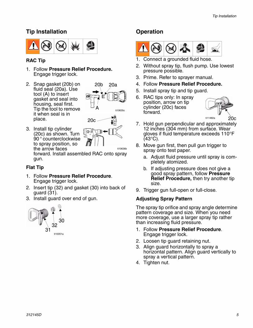
Tip Installation
RAC Tip
1. Follow Pressure Relief Procedure. Engage trigger lock.
2. Snap gasket (20b) on fluid seal (20a). Use tool (A) to insert gasket and seal into housing, seal first. Tip the tool to remove it when seal is in place.
3. Install tip cylinder (20c) as shown. Turn 90 ° counterclockwise to spray position, so the arrow faces forward. Install assembled RAC onto spray gun.
Flat Tip
1. Follow Pressure Relief Procedure. Engage trigger lock.
2. Insert tip (32) and gasket (30) into back of guard (31).
3. Install guard over end of gun.
Operation
1. Connect a grounded fluid hose.2. Without spray tip, flush pump. Use lowest
pressure possible.3. Prime. Refer to sprayer manual.4. Follow Pressure Relief Procedure.5. Install spray tip and tip guard.6. RAC tips only: In spray
position, arrow on tip cylinder (20c) faces forward.
7. Hold gun perpendicular and approximately 12 inches (304 mm) from surface. Wear gloves if fluid temperature exceeds 110°F (43°C).
8. Move gun first, then pull gun trigger to spray onto test paper.a. Adjust fluid pressure until spray is com-
pletely atomized.b. If adjusting pressure does not give a
good spray pattern, follow Pressure Relief Procedure, then try another tip size.
9. Trigger gun full-open or full-close.
Adjusting Spray Pattern
The spray tip orifice and spray angle determine pattern coverage and size. When you need more coverage, use a larger spray tip rather than increasing fluid pressure.1. Follow Pressure Relief Procedure.
Engage trigger lock.2. Loosen tip guard retaining nut.3. Align guard horizontally to spray a
horizontal pattern. Align guard vertically to spray a vertical pattern.
4. Tighten nut.
20c
A
20a20b
ti10635c
ti10051a
3032
31
20cti11482a
ti10636b

Maintenance
6 312145D
Cleaning Tips/Clearing Clogs
1. Follow Pressure Relief Procedure. Engage trigger lock.
2. Clean spray tip as follows:a. RAC tips: Rotate tip 180°
so arrow on tip cylinder (20c) faces backward. Disengage trigger lock. Trigger gun into pail or onto ground to remove clog. Engage trigger lock. Rotate tip 180° back to spray position.
b. Flat tips: Remove tip and clean with a solvent-soaked brush.
3. RAC tips: If tip is still clogged:a. Shut off sprayer and disconnect power
source.b. Open fluid drain valve (see System
Requirements on page 4) to relieve pressure.
c. Remove and clean spray tip.
Maintenance
Flushing
Flush pump and gun before fluid can dry in it. If available, use flushing procedure provided in your pump or sprayer manual instead of this procedure.1. Follow Pressure Relief Procedure.
Engage trigger lock.2. Remove spray tip and guard from gun.
Clean with solvent.3. Put the pump intake in a grounded pail of
compatible solvent.4. Start pump at its lowest pressure.
5. Disengage trigger lock, then trigger gun into the paint pail. When solvent appears, release trigger.
6. Trigger gun into solvent pail. Circulate fluid until system is thoroughly flushed.
7. Follow Pressure Relief Procedure. Engage trigger lock.
Cleaning/Replacing Filter
1. Follow Pressure Relief Procedure. Engage trigger lock.
2. Disconnect trigger guard from gun body by pushing up on guard hook and pulling it out of notch.
3. The trigger guard beneath the gun handle can then be used as a wrench to loosen the nut.
4. When alignment notches are no longer engaged, use your hand to twist handle and remove it from gun head.
5. Remove filter.6. Clean filter using a soft brush.7. Replace filter.8. Apply light coating of grease to threads and
then attach.9. Use trigger guard to tighten the nut.10.Reattach the trigger guard to the gun.
Cleanup
Flush gun after each work shift and store in a dry location. Do not leave the gun or any parts in water or cleaning solvents.
Clean tip and tip guard at end of each work day.
Failure to clean or replace the filter or damaged handle bore can result in serious injury.Before performing any maintenance on the gun, read all warnings in this manual and relieve pressure.
20cti11483a
ti5052a
ti5054a
Repair
312145D 7
Repair
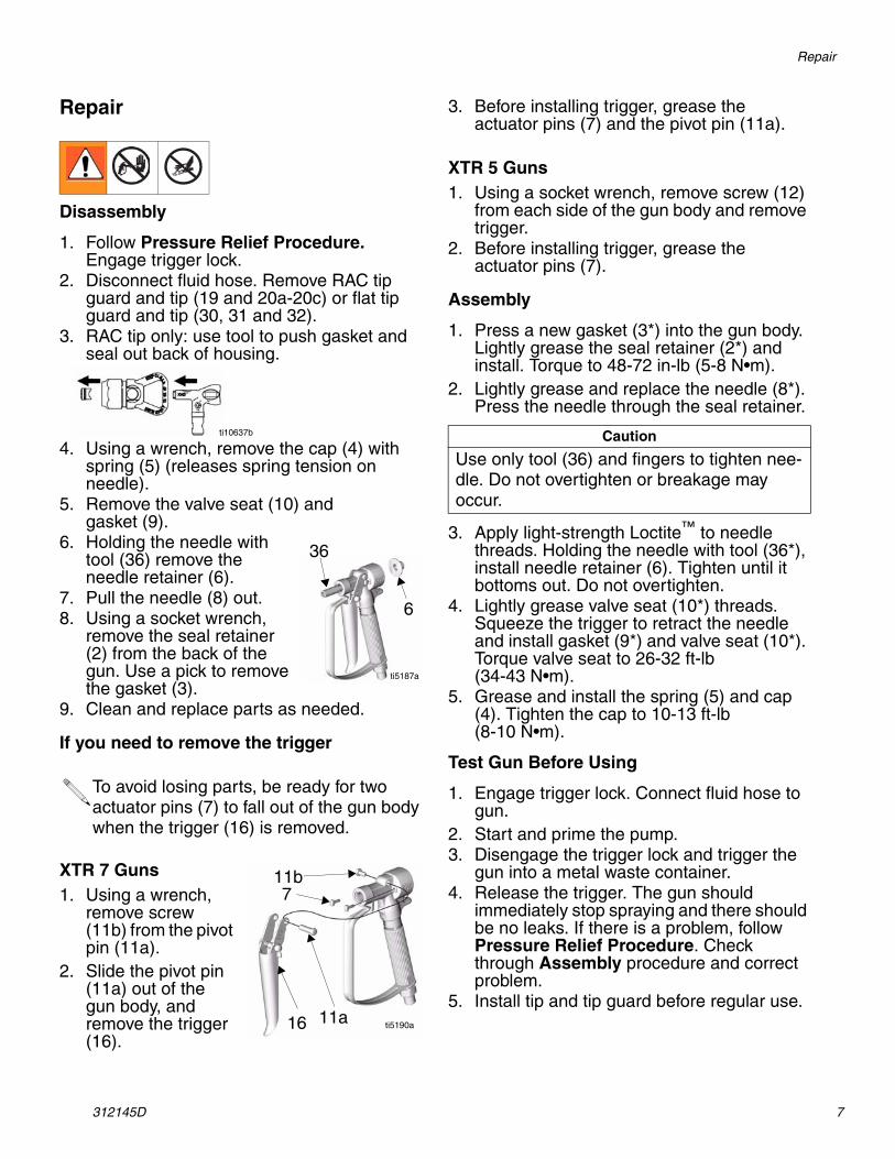
Disassembly
1. Follow Pressure Relief Procedure. Engage trigger lock.
2. Disconnect fluid hose. Remove RAC tip guard and tip (19 and 20a-20c) or flat tip guard and tip (30, 31 and 32).
3. RAC tip only: use tool to push gasket and seal out back of housing.
4. Using a wrench, remove the cap (4) with spring (5) (releases spring tension on needle).
5. Remove the valve seat (10) andgasket (9).
6. Holding the needle with tool (36) remove the needle retainer (6).
7. Pull the needle (8) out.8. Using a socket wrench,
remove the seal retainer (2) from the back of the gun. Use a pick to remove the gasket (3).
9. Clean and replace parts as needed.
If you need to remove the trigger
XTR 7 Guns1. Using a wrench,
remove screw (11b) from the pivot pin (11a).
2. Slide the pivot pin (11a) out of the gun body, and remove the trigger (16).
3. Before installing trigger, grease the actuator pins (7) and the pivot pin (11a).
XTR 5 Guns1. Using a socket wrench, remove screw (12)
from each side of the gun body and remove trigger.
2. Before installing trigger, grease the actuator pins (7).
Assembly
1. Press a new gasket (3*) into the gun body. Lightly grease the seal retainer (2*) and install. Torque to 48-72 in-lb (5-8 N•m).
2. Lightly grease and replace the needle (8*). Press the needle through the seal retainer.
3. Apply light-strength Loctite™ to needle threads. Holding the needle with tool (36*), install needle retainer (6). Tighten until it bottoms out. Do not overtighten.
4. Lightly grease valve seat (10*) threads. Squeeze the trigger to retract the needle and install gasket (9*) and valve seat (10*). Torque valve seat to 26-32 ft-lb(34-43 N•m).
5. Grease and install the spring (5) and cap (4). Tighten the cap to 10-13 ft-lb(8-10 N•m).
Test Gun Before Using
1. Engage trigger lock. Connect fluid hose to gun.
2. Start and prime the pump.3. Disengage the trigger lock and trigger the
gun into a metal waste container.4. Release the trigger. The gun should
immediately stop spraying and there should be no leaks. If there is a problem, follow Pressure Relief Procedure. Check through Assembly procedure and correct problem.
5. Install tip and tip guard before regular use.
To avoid losing parts, be ready for two actuator pins (7) to fall out of the gun body when the trigger (16) is removed.
ti10637b
36
6
ti5187a
11b7
11a16 ti5190a
Caution
Use only tool (36) and fingers to tighten nee-dle. Do not overtighten or breakage may occur.
Parts
8 312145D
Parts
45
6
2*3*111b†
78*9*
10* 11a†
21*
26
16c†
16a†
16b†
14b
14a
13
XTR 5 trigger attachment
12†
12†
15 (XTR 5 only‡)
ti5192c
24
24

Parts
312145D 9
Parts
▲ Replacement Danger and Warning labels, tags, and cards are available at no cost.
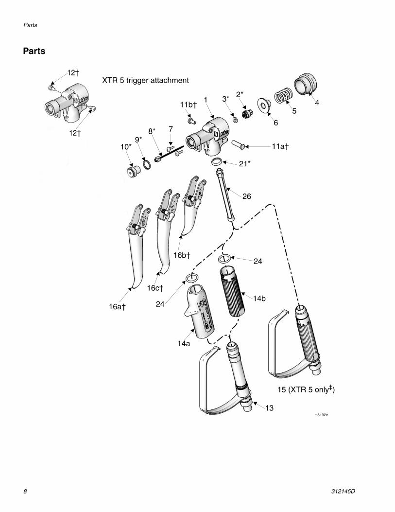
* Parts included in Repair Kit 248837, pur-chased separately.
† Parts included in Trigger Kits 287449 (16a), 287450 (16b), and 287451 (16c), purchased separately.
‡ NOTE: Handle is not pressure rated for use with the XTR 7. For an XTR 7, order handle 13 and sleeve 14a or 14b depending on your model (see Table 1).
Ref Part Description Qty1 15J771 BODY, gun, aluminum,
(XTR 5 only)1
15E178 BODY, gun, sst (XTR 7 only) 12* 245881 SEAL, retainer assembly 13* n/a GASKET (kit 248837 only, not
sold separately)1
4 15K000 CAP, end (XTR 5 only) 115A864 CAP, end (XTR 7 only) 1
5 117350 SPRING, 16 15E088 RETAINER, needle 17 15E085 PIN, actuator 28* 248591 NEEDLE 19* 156766 GASKET 110* 245858 SEAT, valve 111a† 192272 PIN, pivot (XTR 7 only) 111b† 203953 SCREW, cap, hex-hd;
10-24 x 3/8 in. (10 mm)[XTR7 only]
1
12† 117602 SCREW, shoulder, pan hd;8-32 x 5/16 in. (8 mm)[XTR 5 only]
2
13 248952 HANDLE, includes trigger guard, swivel, tube, and o-ring; see Tables 1 and 2
1
14a 276997 HANDLE SLEEVE, insulated, (see Tables 1 and 2)
1
14b 15E083 HANDLE SLEEVE, 1 in. (25 mm), (see Tables 1 and 2)
1
15‡ 255275 HANDLE, includes trigger guard, swivel, and tube, 1 in. (25 mm) OD, (XTR 5 only, see Table 2)
1
16a† 287449 TRIGGER KIT, also includes 11a, 11b, and 12, see Tables 1 and 2,
1
16b† 287450 TRIGGER KIT, also includes 11a, 11b, and 12, see Tables 1 and 2
1
16c† 287451 TRIGGER KIT, also includes 11a, 11b, and 12, see Tables 1 and 2
1
21* 179733 SEAL, sleeve 124 n/a O-RING (kit 248952 only, not
sold separately)1
26 287032 FILTER, 60 mesh, included with gun
1
287034 FILTER, 60 and 100 mesh combo
29▲ 222385 TAG, warning (not shown) 136* 194744 TOOL, repair, packing 1
Table 1: XTR 7 Models
XTR 7 Gun
Part No.
Reference Numbers
13 14a 14b 16a 16b 16c 19 20
XTR700 ✔ ✔ ✔ ✔
XTR701 ✔ ✔ ✔
XTR702 ✔ ✔ ✔ ✔ ✔
XTR703 ✔ ✔ ✔ ✔ ✔
XTR704 ✔ ✔ ✔ ✔ ✔
XTR705 ✔ ✔ ✔ ✔ ✔
Table 2: XTR 5 Models
XTR 5 Gun
Part No.
Reference Numbers
13 14a 14b 15 16a 16b 16c 19 20
XTR500 ✔ ✔ ✔
XTR501 ✔ ✔
XTR502 ✔ ✔ ✔ ✔ ✔
XTR503 ✔ ✔ ✔ ✔ ✔
XTR504 ✔ ✔ ✔ ✔
XTR505 ✔ ✔ ✔ ✔

Tip and Guard
10 312145D
Tip and Guard
✓ Included in OneSeal™ Repair Kit XHD010(5 each per package, purchase separately).
RAC Tip Flat Tip
Ref Part Description Qty
19 XHD001 GUARD, RAC tip (see Tables 1 and 2)
1
20 XHDxxx SWITCH, RAC tip, 519 size included (includes 20a - 20c, see Tables 1 and 2)
1
20a✓ SEAL, fluid 1
20b✓ GASKET 1
20c TIP, spray, XHD RAC 1
30 166969 GASKET, (XTR501 and XTR701 only)
31 220251 GUARD, flat tip (XTR501 and XTR701 only)
1
32 163519 TIP, flat (XTR501 and XTR701 only)
1
20a20b
19 20cti10050a
3032
31ti10051a

Technical Data
312145D 11
Technical Data
*Results are maximum readings taken at 6000 psi (41 MPa, 414 bar), with HD519 tip, using water. Sound power level was tested to ISO 9614-2.
Related Manuals
This manual is available in the following languages. Also see www.graco.com for the latest translations.
Maximum working pressure:XTR 5 . . . . . . . . . . . . . . . . . . . . . . . . . . . 5000 psi (35 MPa, 345 bar)XTR 7 . . . . . . . . . . . . . . . . . . . . . . . . . . . 7250 psi (50 MPa, 500 bar)Fluid orifice. . . . . . . . . . . . . . . . . . . . . . . 0.090 in. (2.3 mm)Fluid inlet . . . . . . . . . . . . . . . . . . . . . . . . 1/4 npsm (m)Max. fluid temperature . . . . . . . . . . . . . . 160°F (71°C)Sound pressure . . . . . . . . . . . . . . . . . . . 84.3 dB(A)*Sound power . . . . . . . . . . . . . . . . . . . . . 95.7 dB(A)*Wetted parts. . . . . . . . . . . . . . . . . . . . . . aluminum, stainless steel, acetal, polyethylene, nylon,
polypropylene, carbide, polyurethane, solvent-resistant o-rings.
Language Manual
Chinese 312293Dutch 312138English 312145French 312294German 312295Italian 312549Japanese 312296Korean 312297Portuguese 312136Russian 312137Spanish 312298Swedish 312139

All written and visual data contained in this document reflects the latest product information available at the time of publication. Graco reserves the right to make changes at any time without notice.
This manual contains English. MM 312145
Graco Headquarters: MinneapolisInternational Offices: Belgium, China, Japan, Korea
GRACO INC. P.O. BOX 1441 MINNEAPOLIS, MN 55440-1441Copyright 2007, Graco Inc. is registered to ISO 9001
www.graco.comRevised 04/2009
Graco Standard WarrantyGraco warrants all equipment referenced in this document which is manufactured by Graco and bearing its name to be free from defects in material and workmanship on the date of sale to the original purchaser for use. With the exception of any special, extended, or limited warranty published by Graco, Graco will, for a period of twelve months from the date of sale, repair or replace any part of the equipment determined by Graco to be defective. This warranty applies only when the equipment is installed, operated and maintained in accordance with Graco’s written recommendations.
This warranty does not cover, and Graco shall not be liable for general wear and tear, or any malfunction, damage or wear caused by faulty installation, misapplication, abrasion, corrosion, inadequate or improper maintenance, negligence, accident, tampering, or substitution of non-Graco component parts. Nor shall Graco be liable for malfunction, damage or wear caused by the incompatibility of Graco equipment with structures, accessories, equipment or materials not supplied by Graco, or the improper design, manufacture, installation, operation or maintenance of structures, accessories, equipment or materials not supplied by Graco.
This warranty is conditioned upon the prepaid return of the equipment claimed to be defective to an authorized Graco distributor for verification of the claimed defect. If the claimed defect is verified, Graco will repair or replace free of charge any defective parts. The equipment will be returned to the original purchaser transportation prepaid. If inspection of the equipment does not disclose any defect in material or workmanship, repairs will be made at a reasonable charge, which charges may include the costs of parts, labor, and transportation.
THIS WARRANTY IS EXCLUSIVE, AND IS IN LIEU OF ANY OTHER WARRANTIES, EXPRESS OR IMPLIED, INCLUDING BUT NOT LIMITED TO WARRANTY OF MERCHANTABILITY OR WARRANTY OF FITNESS FOR A PARTICULAR PURPOSE.
Graco’s sole obligation and buyer’s sole remedy for any breach of warranty shall be as set forth above. The buyer agrees that no other remedy (including, but not limited to, incidental or consequential damages for lost profits, lost sales, injury to person or property, or any other incidental or consequential loss) shall be available. Any action for breach of warranty must be brought within two (2) years of the date of sale.
GRACO MAKES NO WARRANTY, AND DISCLAIMS ALL IMPLIED WARRANTIES OF MERCHANTABILITY AND FITNESS FOR A PARTICULAR PURPOSE, IN CONNECTION WITH ACCESSORIES, EQUIPMENT, MATERIALS OR COMPONENTS SOLD BUT NOT MANUFACTURED BY GRACO. These items sold, but not manufactured by Graco (such as electric motors, switches, hose, etc.), are subject to the warranty, if any, of their manufacturer. Graco will provide purchaser with reasonable assistance in making any claim for breach of these warranties.
In no event will Graco be liable for indirect, incidental, special or consequential damages resulting from Graco supplying equipment hereunder, or the furnishing, performance, or use of any products or other goods sold hereto, whether due to a breach of contract, breach of warranty, the negligence of Graco, or otherwise.
FOR GRACO CANADA CUSTOMERSThe Parties acknowledge that they have required that the present document, as well as all documents, notices and legal proceedings entered into, given or instituted pursuant hereto or relating directly or indirectly hereto, be drawn up in English. Les parties reconnaissent avoir convenu que la rédaction du présente document sera en Anglais, ainsi que tous documents, avis et procédures judiciaires exécutés, donnés ou intentés, à la suite de ou en rapport, directement ou indirectement, avec les procédures concernées.
Graco Information
TO PLACE AN ORDER, contact your Graco distributor or call to identify the nearest distributor.Phone: 612-623-6921 or Toll Free: 1-800-328-0211 Fax: 612-378-3505
For the latest information about Graco products, visit www.graco.com.