Embed Size (px)
Citation preview
8/12/2019 311238 Xtreme - Air Motor
http://slidepdf.com/reader/full/311238-xtreme-air-motor 1/46
Instructions-Parts
NXT ® Air Motor
Conforms toFM std 3600 & 3610
for use in Class I Div 1Group D
T3C Hazardous locations
0359
II 1 GEEx ia IIA T3
Nemko06ATEX1124
Models with DataTrak™ display
include agency approvals listed below.
TI8621a
With Linear Sensor
Standard
With DataTrak ™
Important Safety InstructionsRead all warnings and instructions in this manual.
Save these instructions.
See page 3 for model information.
100 psi (0.7 MPa, 7.0 bar) Maximum Working Pressure
Updated technical information and repair videos are available atwww.graco.com. Click on “Tech Support”, and then enter “NXT” in the
“Search by Keyword” field.
For use with high performance finishing and coating pumps in hazardous ornon-hazardous locations. For professional use only.
311238ZAEEN
8/12/2019 311238 Xtreme - Air Motor
http://slidepdf.com/reader/full/311238-xtreme-air-motor 2/46
2 311238ZAE
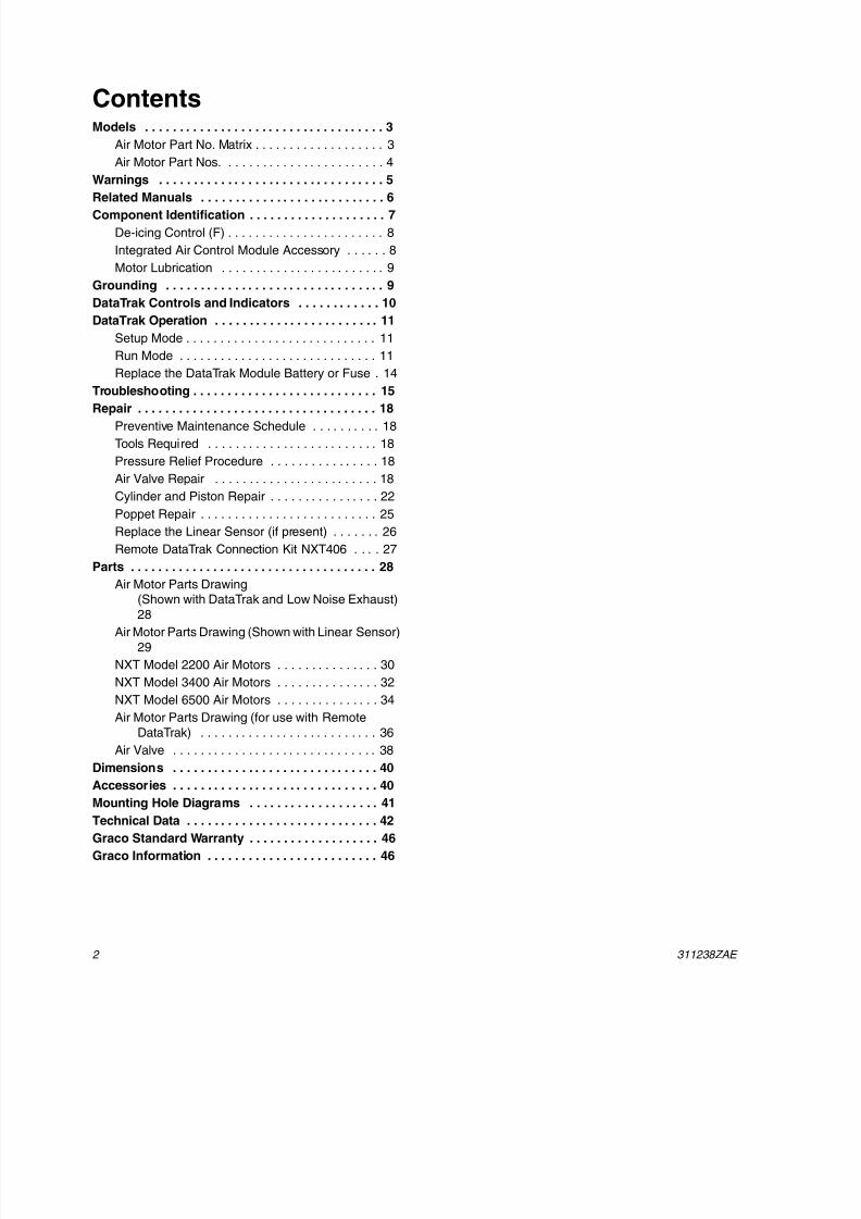
ContentsModels . . . . . . . . . . . . . . . . . . . . . . . . . . . . . . . . . . . 3
Air Motor Part No. Matrix . . . . . . . . . . . . . . . . . . . 3
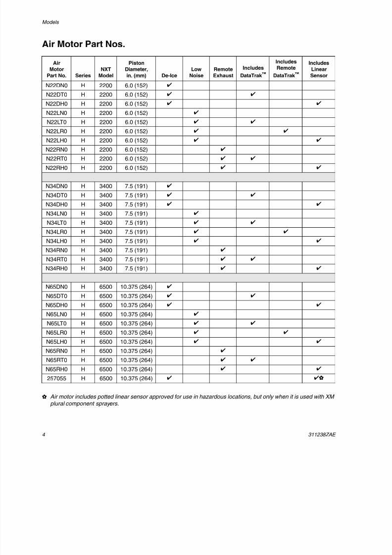
Air Motor Part Nos. . . . . . . . . . . . . . . . . . . . . . . . 4
Warnings . . . . . . . . . . . . . . . . . . . . . . . . . . . . . . . . . 5
Related Manuals . . . . . . . . . . . . . . . . . . . . . . . . . . . 6
Component Identification . . . . . . . . . . . . . . . . . . . . 7
De-icing Control (F) . . . . . . . . . . . . . . . . . . . . . . . 8
Integrated Air Control Module Accessory . . . . . . 8
Motor Lubrication . . . . . . . . . . . . . . . . . . . . . . . . 9
Grounding . . . . . . . . . . . . . . . . . . . . . . . . . . . . . . . . 9
DataTrak Controls and Indicators . . . . . . . . . . . . 10
DataTrak Operation . . . . . . . . . . . . . . . . . . . . . . . . 11
Setup Mode . . . . . . . . . . . . . . . . . . . . . . . . . . . . 11
Run Mode . . . . . . . . . . . . . . . . . . . . . . . . . . . . . 11
Replace the DataTrak Module Battery or Fuse . 14
Troubleshooting . . . . . . . . . . . . . . . . . . . . . . . . . . . 15
Repair . . . . . . . . . . . . . . . . . . . . . . . . . . . . . . . . . . . 18
Preventive Maintenance Schedule . . . . . . . . . . 18
Tools Required . . . . . . . . . . . . . . . . . . . . . . . . . 18
Pressure Relief Procedure . . . . . . . . . . . . . . . . 18
Air Valve Repair . . . . . . . . . . . . . . . . . . . . . . . . 18
Cylinder and Piston Repair . . . . . . . . . . . . . . . . 22
Poppet Repair . . . . . . . . . . . . . . . . . . . . . . . . . . 25
Replace the Linear Sensor (if present) . . . . . . . 26
Remote DataTrak Connection Kit NXT406 . . . . 27
Parts . . . . . . . . . . . . . . . . . . . . . . . . . . . . . . . . . . . . 28
Air Motor Parts Drawing(Shown with DataTrak and Low Noise Exhaust)
28
Air Motor Parts Drawing (Shown with Linear Sensor)
29
NXT Model 2200 Air Motors . . . . . . . . . . . . . . . 30
NXT Model 3400 Air Motors . . . . . . . . . . . . . . . 32
NXT Model 6500 Air Motors . . . . . . . . . . . . . . . 34
Air Motor Parts Drawing (for use with Remote
DataTrak) . . . . . . . . . . . . . . . . . . . . . . . . . . 36
Air Valve . . . . . . . . . . . . . . . . . . . . . . . . . . . . . . 38
Dimensions . . . . . . . . . . . . . . . . . . . . . . . . . . . . . . 40Accessories . . . . . . . . . . . . . . . . . . . . . . . . . . . . . . 40
Mounting Hole Diagrams . . . . . . . . . . . . . . . . . . . 41
Technical Data . . . . . . . . . . . . . . . . . . . . . . . . . . . . 42
Graco Standard Warranty . . . . . . . . . . . . . . . . . . . 46
Graco Information . . . . . . . . . . . . . . . . . . . . . . . . . 46
8/12/2019 311238 Xtreme - Air Motor
http://slidepdf.com/reader/full/311238-xtreme-air-motor 3/46
Models
311238ZAE 3
Models
Air Motor Part No. Matrix
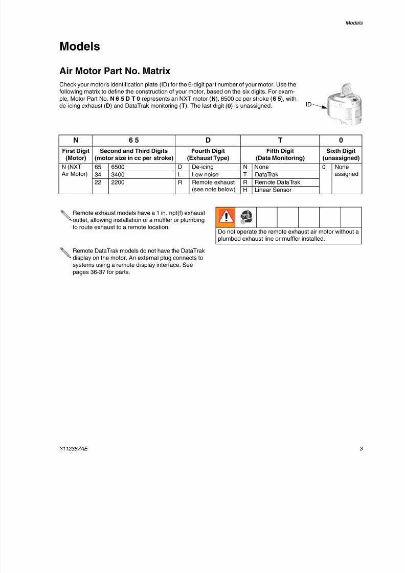
Check your motor’s identification plate (ID) for the 6-digit part number of your motor. Use the
following matrix to define the construction of your motor, based on the six digits. For exam-ple, Motor Part No. N 6 5 D T 0 represents an NXT motor (N), 6500 cc per stroke (6 5), withde-icing exhaust (D) and DataTrak monitoring (T). The last digit (0) is unassigned. ID
N 6 5 D T 0
First Digit(Motor)
Second and Third Digits(motor size in cc per stroke)
Fourth Digit(Exhaust Type)
Fifth Digit(Data Monitoring)
Sixth Digit(unassigned)
N (NXTAir Motor)
65 6500 D De-icing N None 0 Noneassigned34 3400 L Low noise T DataTrak
22 2200 R Remote exhaust(see note below)
R Remote DataTrak
H Linear Sensor
Remote exhaust models have a 1 in. npt(f) exhaustoutlet, allowing installation of a muffler or plumbing
to route exhaust to a remote location.
Remote DataTrak models do not have the DataTrakdisplay on the motor. An external plug connects tosystems using a remote display interface. See
pages 36-37 for parts.
Do not operate the remote exhaust air motor without aplumbed exhaust line or muffler installed.
8/12/2019 311238 Xtreme - Air Motor
http://slidepdf.com/reader/full/311238-xtreme-air-motor 4/46
8/12/2019 311238 Xtreme - Air Motor
http://slidepdf.com/reader/full/311238-xtreme-air-motor 5/46
Warnings
311238ZAE 5
Warnings
The following warnings are for the setup, use, grounding, maintenance, and repair of this equipment. The exclama-
tion point symbol alerts you to a general warning and the hazard symbols refer to procedure-specific risks. Referback to these Warnings. Additional, product-specific warnings may be found throughout the body of this manual
where applicable.
WARNING
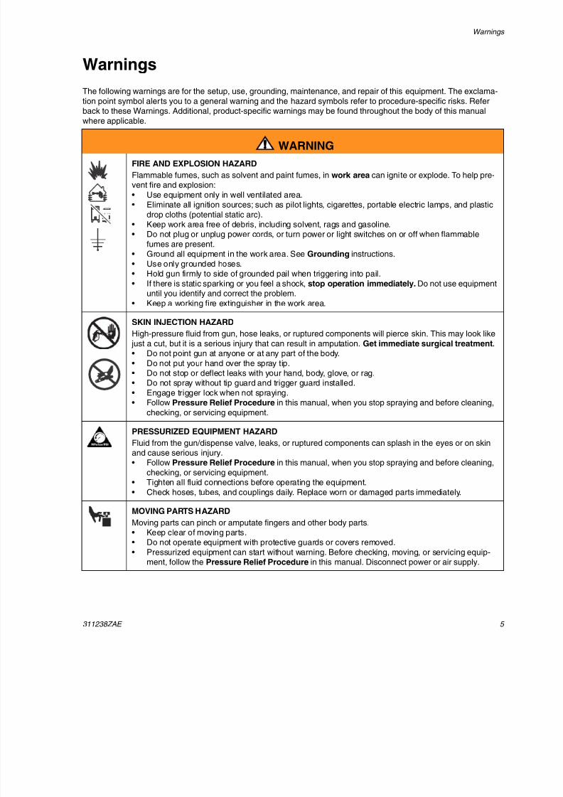
FIRE AND EXPLOSION HAZARD
Flammable fumes, such as solvent and paint fumes, in work area can ignite or explode. To help pre-vent fire and explosion:
• Use equipment only in well ventilated area.• Eliminate all ignition sources; such as pilot lights, cigarettes, portable electric lamps, and plastic
drop cloths (potential static arc).• Keep work area free of debris, including solvent, rags and gasoline.• Do not plug or unplug power cords, or turn power or light switches on or off when flammable
fumes are present.
• Ground all equipment in the work area. See Grounding instructions.• Use only grounded hoses.• Hold gun firmly to side of grounded pail when triggering into pail.
• If there is static sparking or you feel a shock, stop operation immediately. Do not use equipmentuntil you identify and correct the problem.
• Keep a working fire extinguisher in the work area.
SKIN INJECTION HAZARD
High-pressure fluid from gun, hose leaks, or ruptured components will pierce skin. This may look like
just a cut, but it is a serious injury that can result in amputation. Get immediate surgical treatment.• Do not point gun at anyone or at any part of the body.
• Do not put your hand over the spray tip.
• Do not stop or deflect leaks with your hand, body, glove, or rag.• Do not spray without tip guard and trigger guard installed.
• Engage trigger lock when not spraying.• Follow Pressure Relief Procedure in this manual, when you stop spraying and before cleaning,
checking, or servicing equipment.
PRESSURIZED EQUIPMENT HAZARD
Fluid from the gun/dispense valve, leaks, or ruptured components can splash in the eyes or on skinand cause serious injury.• Follow Pressure Relief Procedure in this manual, when you stop spraying and before cleaning,
checking, or servicing equipment.• Tighten all fluid connections before operating the equipment.
• Check hoses, tubes, and couplings daily. Replace worn or damaged parts immediately.
MOVING PARTS HAZARD
Moving parts can pinch or amputate fingers and other body parts.• Keep clear of moving parts.• Do not operate equipment with protective guards or covers removed.
• Pressurized equipment can start without warning. Before checking, moving, or servicing equip-ment, follow the Pressure Relief Procedure in this manual. Disconnect power or air supply.
8/12/2019 311238 Xtreme - Air Motor
http://slidepdf.com/reader/full/311238-xtreme-air-motor 6/46
Related Manuals
6 311238ZAE
Related Manuals
Component manuals in U.S. English:
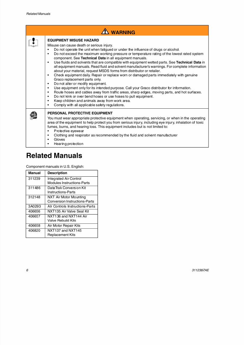
EQUIPMENT MISUSE HAZARD
Misuse can cause death or serious injury.
• Do not operate the unit when fatigued or under the influence of drugs or alcohol.
• Do not exceed the maximum working pressure or temperature rating of the lowest rated systemcomponent. See Technical Data in all equipment manuals.
• Use fluids and solvents that are compatible with equipment wetted parts. See Technical Data inall equipment manuals. Read fluid and solvent manufacturer’s warnings. For complete information
about your material, request MSDS forms from distributor or retailer.• Check equipment daily. Repair or replace worn or damaged parts immediately with genuine
Graco replacement parts only.• Do not alter or modify equipment.
• Use equipment only for its intended purpose. Call your Graco distributor for information.• Route hoses and cables away from traffic areas, sharp edges, moving parts, and hot surfaces.• Do not kink or over bend hoses or use hoses to pull equipment.
• Keep children and animals away from work area.• Comply with all applicable safety regulations.
PERSONAL PROTECTIVE EQUIPMENT
You must wear appropriate protective equipment when operating, servicing, or when in the operating
area of the equipment to help protect you from serious injury, including eye injury, inhalation of toxicfumes, burns, and hearing loss. This equipment includes but is not limited to:• Protective eyewear
• Clothing and respirator as recommended by the fluid and solvent manufacturer• Gloves
• Hearing protection
WARNING
Manual Description
311239 Integrated Air ControlModules Instructions-Parts
311486 DataTrak Conversion KitInstructions-Parts
312148 NXT Air Motor Mounting
Conversion Instructions-Parts
3A0293 AIr Controls Instructions-Parts
406656 NXT135 Air Valve Seal Kit
406657 NXT136 and NXT144 AirValve Rebuild Kits
406658 Air Motor Repair Kits
406820 NXT137 and NXT145Replacement Kits
8/12/2019 311238 Xtreme - Air Motor
http://slidepdf.com/reader/full/311238-xtreme-air-motor 7/46
Component Identification
311238ZAE 7
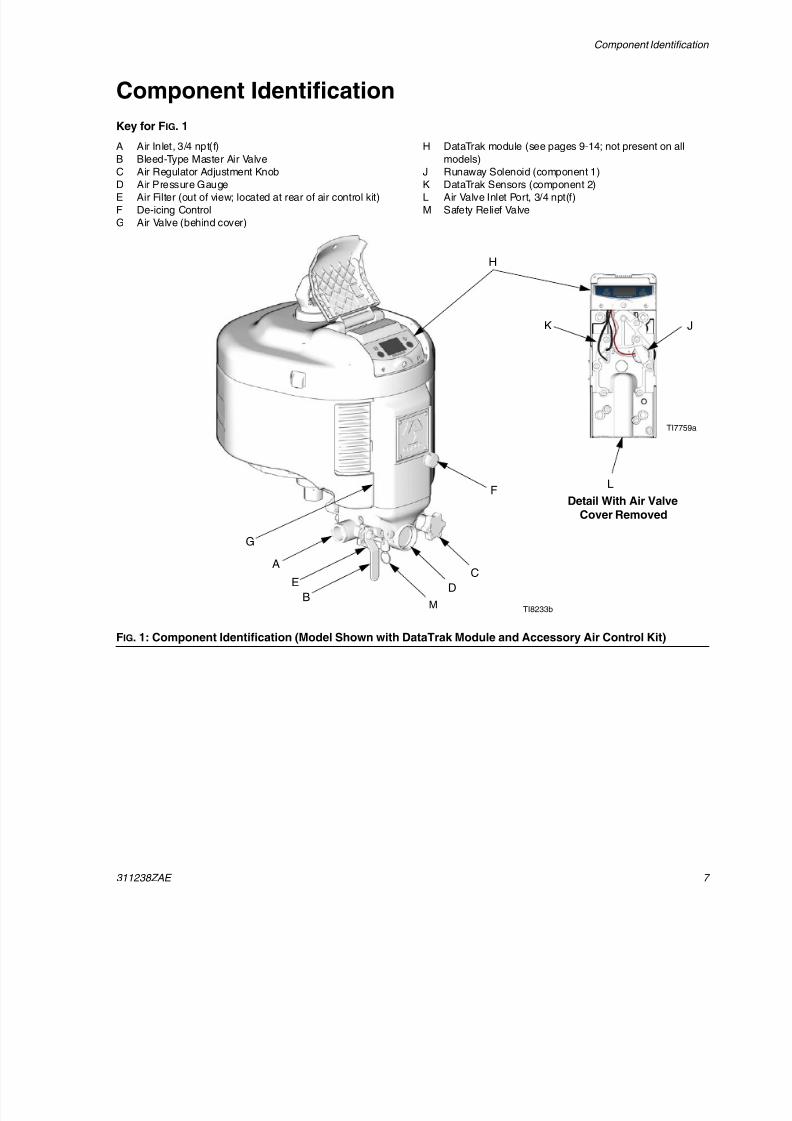
Component Identification
Key for FIG. 1
A Air Inlet, 3/4 npt(f)
B Bleed-Type Master Air Valve
C Air Regulator Adjustment KnobD Air Pressure Gauge
E Air Filter (out of view; located at rear of air control kit)
F De-icing Control
G Air Valve (behind cover)
H DataTrak module (see pages 9-14; not present on all
models)
J Runaway Solenoid (component 1)K DataTrak Sensors (component 2)
L Air Valve Inlet Port, 3/4 npt(f)
M Safety Relief Valve
FIG. 1: Component Identification (Model Shown with DataTrak Module and Accessory Air Control Kit)
TI8233b
H
K J
F
G
A
Detail With Air ValveCover Removed
TI7759a
B
C
DE
L
M
8/12/2019 311238 Xtreme - Air Motor
http://slidepdf.com/reader/full/311238-xtreme-air-motor 8/46
Component Identification
8 311238ZAE
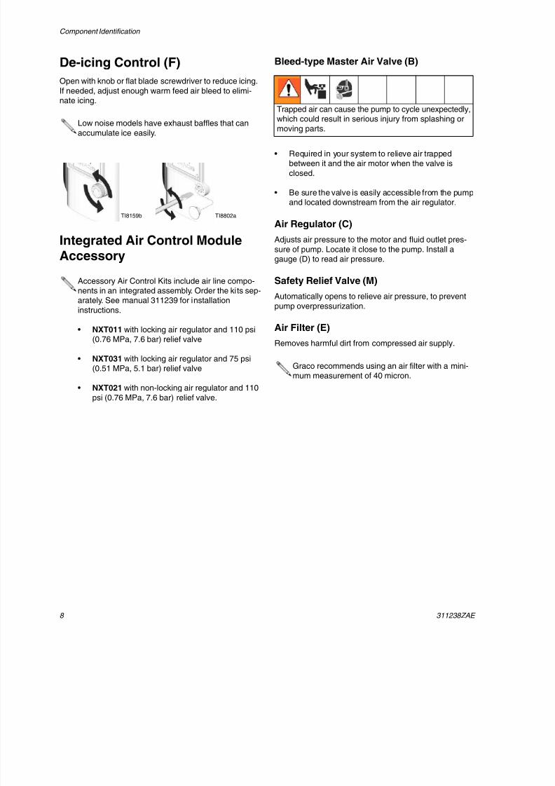
De-icing Control (F)
Open with knob or flat blade screwdriver to reduce icing.
If needed, adjust enough warm feed air bleed to elimi-nate icing.
Integrated Air Control ModuleAccessory
Bleed-type Master Air Valve (B)
• Required in your system to relieve air trappedbetween it and the air motor when the valve is
closed.
• Be sure the valve is easily accessible from the pumpand located downstream from the air regulator.
Air Regulator (C)
Adjusts air pressure to the motor and fluid outlet pres-
sure of pump. Locate it close to the pump. Install agauge (D) to read air pressure.
Safety Relief Valve (M)
Automatically opens to relieve air pressure, to prevent
pump overpressurization.
Air Filter (E)
Removes harmful dirt from compressed air supply.
Low noise models have exhaust baffles that canaccumulate ice easily.
Accessory Air Control Kits include air line compo-nents in an integrated assembly. Order the kits sep-arately. See manual 311239 for installation
instructions.
• NXT011 with locking air regulator and 110 psi(0.76 MPa, 7.6 bar) relief valve
• NXT031 with locking air regulator and 75 psi
(0.51 MPa, 5.1 bar) relief valve
• NXT021 with non-locking air regulator and 110
psi (0.76 MPa, 7.6 bar) relief valve.
TI8802aTI8159b
Trapped air can cause the pump to cycle unexpectedly,which could result in serious injury from splashing or
moving parts.
Graco recommends using an air filter with a mini-mum measurement of 40 micron.
8/12/2019 311238 Xtreme - Air Motor
http://slidepdf.com/reader/full/311238-xtreme-air-motor 9/46
Grounding
311238ZAE 9
Motor Lubrication
Graco does not require lubrication beyond the grease
installed at the factory or through regular maintenance.With good quality compressed air and normal ambient
conditions NXT air motors will run millions of cycles
without additional lubrication.
However, if any of the following criteria apply to yoursystem, you will benefit from installing a 3/4 in. air line
lubricator in the air line before the air motor or fromoccasionally adding oil to an air filter cup.
• Air supply does not contain any oil.
• Air supply is very wet.• Air supply is very dry.• Air motor is run at low air pressure.
• Air motor is run in unusually hot or cold environ-ments.
Areas that benefit from lubrication:
• main piston o-rings(17),
• sliding valve spool(119/108), and• motor detent assembly (113).
Add Lubrication
The three methods for adding lubrication are described
below.
Lubricate Air Valve
Perform these steps annually, or more often dependingon your duty cycle, air pressure, and air quality. Use a
high quality lithium-based grease.
1. Remove the 10 air valve cover screws (124) and airvalve cover (112).
2. Grease all visible moving parts, especially detent(113) and valve pistons (119).
Lubricate Air Filter BowlIf using a motor with integrated air controls, add 50-75ml of oil to the air filter bowl and run the motor for a few
minutes at a fast cycle rate. The oil will move through
the air valve and main piston.
Add Accessory Air Lubricator
If using an air motor with integrated air controls, add anaccessory airline lubricator to the motor inlet. The oil
will move through the air filter.
Graco offers airline lubricators for NXT air motors.
Order 214848 (1/2 in.) for NXT 2200 and NXT 3400air motors. Order 214849 (3/4 in.) for NXT 6500 air
motors.
If using an air motor without integrated air controls, adda standard type filter/regulator/lubricator that is sized forthe specific air motor, such as 217073 (3/4 in.) or
217072 (1/2 in.).
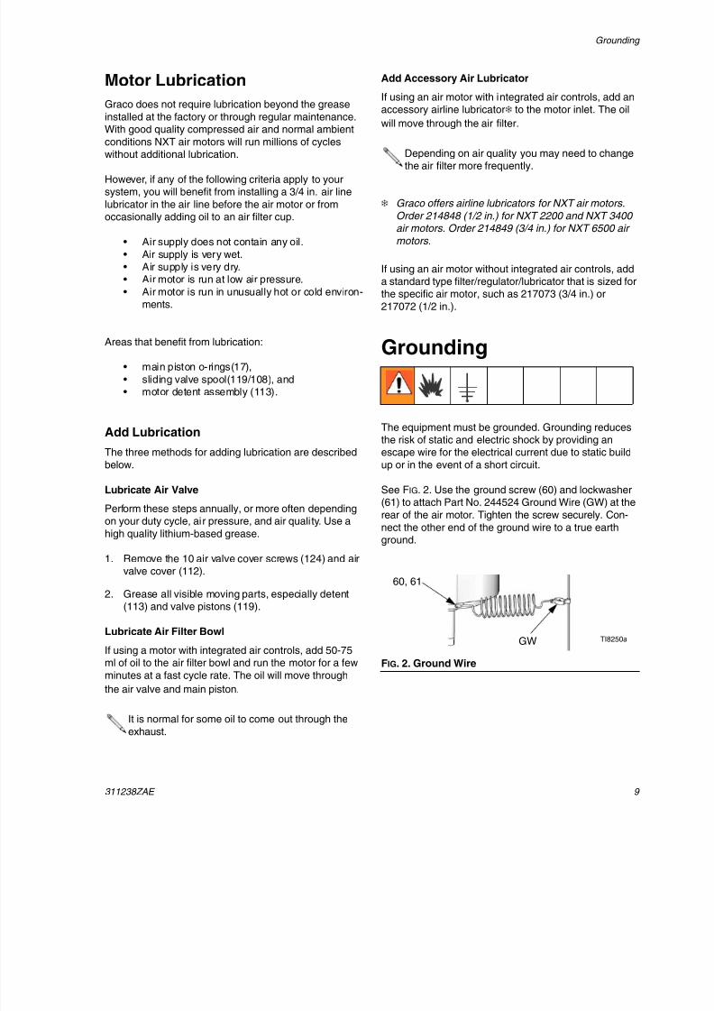
Grounding
The equipment must be grounded. Grounding reducesthe risk of static and electric shock by providing anescape wire for the electrical current due to static build
up or in the event of a short circuit.
See FIG. 2. Use the ground screw (60) and lockwasher(61) to attach Part No. 244524 Ground Wire (GW) at the
rear of the air motor. Tighten the screw securely. Con-
nect the other end of the ground wire to a true earthground.
It is normal for some oil to come out through the
exhaust.
Depending on air quality you may need to changethe air filter more frequently.
FIG. 2. Ground Wire
60, 61
TI8250aGW
8/12/2019 311238 Xtreme - Air Motor
http://slidepdf.com/reader/full/311238-xtreme-air-motor 10/46
DataTrak Controls and Indicators
10 311238ZAE
DataTrak Controls and Indicators
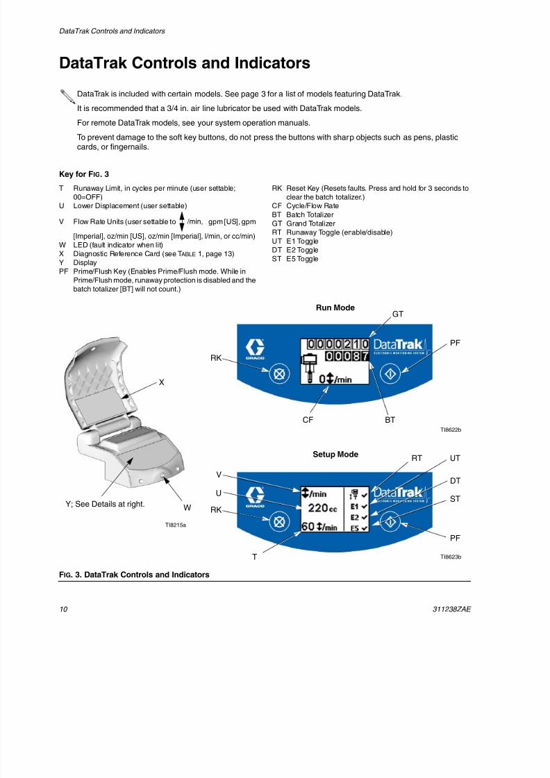
Key for FIG. 3
T Runaway Limit, in cycles per minute (user settable;
00=OFF)
U Lower Displacement (user settable)
V Flow Rate Units (user settable to gpm [US], gpm
[Imperial], oz/min [US], oz/min [Imperial], l/min, or cc/min)
W LED (fault indicator when lit)X Diagnostic Reference Card (see TABLE 1, page 13)
Y Display
PF Prime/Flush Key (Enables Prime/Flush mode. While in
Prime/Flush mode, runaway protection is disabled and the
batch totalizer [BT] will not count.)
RK Reset Key (Resets faults. Press and hold for 3 seconds to
clear the batch totalizer.)
CF Cycle/Flow Rate
BT Batch Totalizer
GT Grand Totalizer
RT Runaway Toggle (enable/disable)
UT E1 ToggleDT E2 Toggle
ST E5 Toggle
DataTrak is included with certain models. See page 3 for a list of models featuring DataTrak.
It is recommended that a 3/4 in. air line lubricator be used with DataTrak models.
For remote DataTrak models, see your system operation manuals.
To prevent damage to the soft key buttons, do not press the buttons with sharp objects such as pens, plasticcards, or fingernails.
/min,
FIG. 3. DataTrak Controls and Indicators
X
WY; See Details at right.
CF BT
GT
V
RT
T
PF
RK
U
UT
DT
ST
Run Mode
Setup Mode
TI8215a
TI8622b
TI8623b
RK
PF
8/12/2019 311238 Xtreme - Air Motor
http://slidepdf.com/reader/full/311238-xtreme-air-motor 11/46
DataTrak Operation
311238ZAE 1
DataTrak Operation
Setup Mode
1. See FIG. 3. Press and hold for 5 seconds until
Setup menu appears.
2. To enter settings for runaway, lower size, and flowrate units, and to enable runaway, E1, E2, and E5
error options, press to change the value, then
to save the value and move the cursor to the
next data field.
3. Move the cursor to the E5 error enable option field,
then press once more to exit Setup mode.
Run Mode
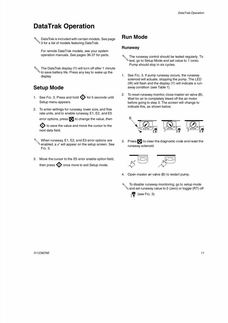
Runaway
1. See FIG. 3. If pump runaway occurs, the runawaysolenoid will actuate, stopping the pump. The LED
(W) will flash and the display (Y) will indicate a run-away condition (see Table 1).
2. To reset runaway monitor, close master air valve (B).
Wait for air to completely bleed off the air motor
before going to step 3. The screen will change toindicate this, as shown below.
3. Press to clear the diagnostic code and reset the
runaway solenoid.
4. Open master air valve (B) to restart pump.
DataTrak is included with certain models. See page3 for a list of models featuring DataTrak.
For remote DataTrak models, see your systemoperation manuals. See pages 36-37 for parts.
The DataTrak display (Y) will turn off after 1 minute
to save battery life. Press any key to wake up thedisplay.
When runaway, E1, E2, and E5 error options areenabled, a will appear on the setup screen. See
FIG. 3.
The runaway control should be tested regularly. Totest, go to Setup Mode and set value to 1 (one).
Pump should stop in six cycles.
To disable runaway monitoring, go to setup mode
and set runaway value to 0 (zero) or toggle (RT) off
(see FIG. 3).
B
8/12/2019 311238 Xtreme - Air Motor
http://slidepdf.com/reader/full/311238-xtreme-air-motor 12/46
DataTrak Operation
12 311238ZAE
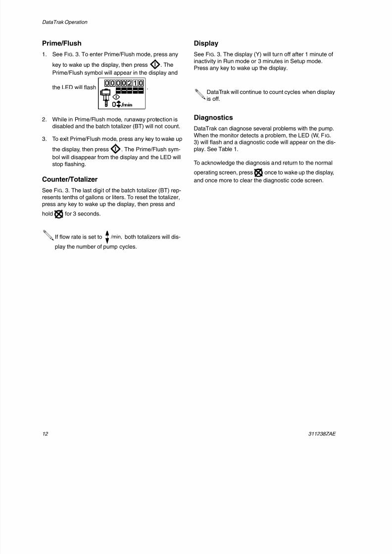
Prime/Flush
1. See FIG. 3. To enter Prime/Flush mode, press any
key to wake up the display, then press . The
Prime/Flush symbol will appear in the display and
the LED will flash .
2. While in Prime/Flush mode, runaway protection isdisabled and the batch totalizer (BT) will not count.
3. To exit Prime/Flush mode, press any key to wake up
the display, then press . The Prime/Flush sym-
bol will disappear from the display and the LED will
stop flashing.
Counter/Totalizer
See FIG. 3. The last digit of the batch totalizer (BT) rep-resents tenths of gallons or liters. To reset the totalizer,
press any key to wake up the display, then press and
hold for 3 seconds.
Display
See FIG. 3. The display (Y) will turn off after 1 minute of
inactivity in Run mode or 3 minutes in Setup mode.Press any key to wake up the display.
Diagnostics
DataTrak can diagnose several problems with the pump.
When the monitor detects a problem, the LED (W, FIG.3) will flash and a diagnostic code will appear on the dis-
play. See Table 1.
To acknowledge the diagnosis and return to the normal
operating screen, press once to wake up the display,and once more to clear the diagnostic code screen.
If flow rate is set to both totalizers will dis-
play the number of pump cycles.
/min,
DataTrak will continue to count cycles when displayis off.
8/12/2019 311238 Xtreme - Air Motor
http://slidepdf.com/reader/full/311238-xtreme-air-motor 13/46
DataTrak Operation
311238ZAE 13
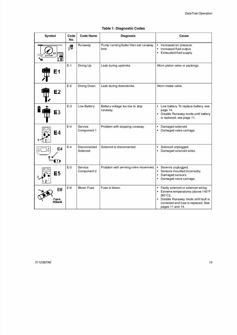
Table 1: Diagnostic Codes
Symbol Code
No.
Code Name Diagnosis Cause
Runaway Pump running faster than set runaway
limit.
• Increased air pressure.
• Increased fluid output.
• Exhausted fluid supply.
E-1 Diving Up Leak during upstroke. Worn piston valve or packings.
E-2 Diving Down Leak during downstroke. Worn intake valve.
E-3 Low Battery Battery voltage too low to stoprunaway.
• Low battery. To replace battery, seepage 14.
• Disable Runaway mode until battery
is replaced; see page 11.
E-4 Service
Component 1
Problem with stopping runaway. • Damaged solenoid.
• Damaged valve carriage.
E-4 Disconnected
Solenoid
Solenoid is disconnected. • Solenoid unplugged.
• Damaged solenoid wires.
E-5 Service
Component 2
Problem with sensing valve movement. • Sensors unplugged.
• Sensors mounted incorrectly.
• Damaged sensors.
• Damaged valve carriage.
E-6 Blown Fuse Fuse is blown. • Faulty solenoid or solenoid wiring.
• Extreme temperatures (above 140°F
[60°C]).
• Disable Runaway mode until fault is
corrected and fuse is replaced. See
pages 11 and 14.
8/12/2019 311238 Xtreme - Air Motor
http://slidepdf.com/reader/full/311238-xtreme-air-motor 14/46
DataTrak Operation
14 311238ZAE
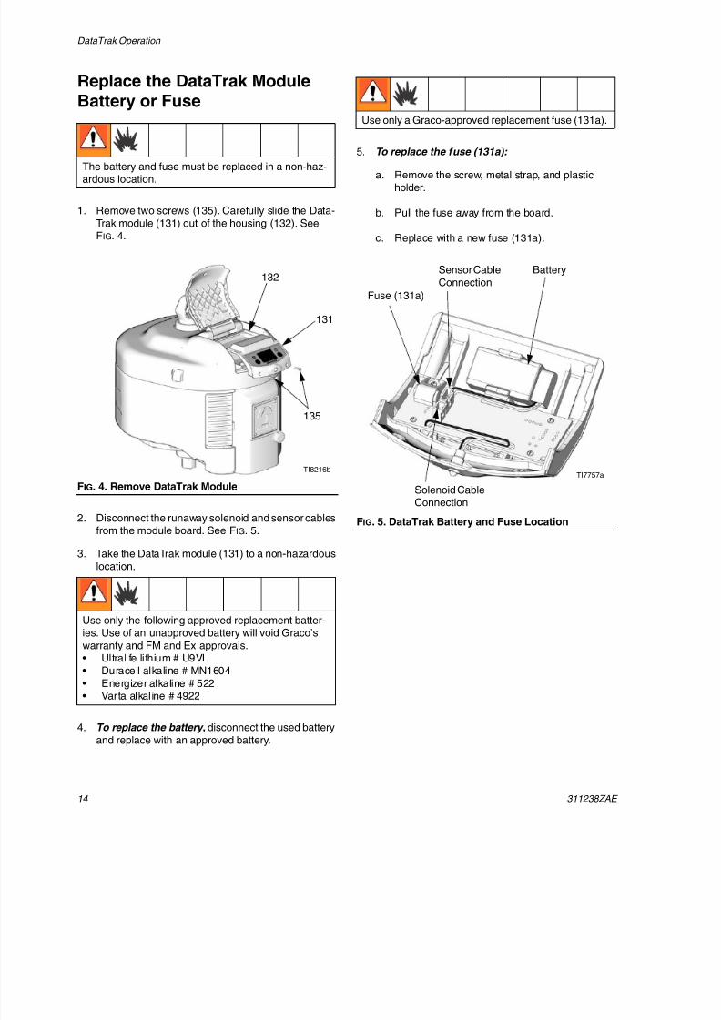
Replace the DataTrak ModuleBattery or Fuse
1. Remove two screws (135). Carefully slide the Data-
Trak module (131) out of the housing (132). SeeFIG. 4.
2. Disconnect the runaway solenoid and sensor cablesfrom the module board. See FIG. 5.
3. Take the DataTrak module (131) to a non-hazardous
location.
4. To replace the battery, disconnect the used battery
and replace with an approved battery.
5. To replace the fuse (131a):
a. Remove the screw, metal strap, and plasticholder.
b. Pull the fuse away from the board.
c. Replace with a new fuse (131a).
The battery and fuse must be replaced in a non-haz-ardous location.
FIG. 4. Remove DataTrak Module
Use only the following approved replacement batter-ies. Use of an unapproved battery will void Graco’s
warranty and FM and Ex approvals.• Ultralife lithium # U9VL• Duracell alkaline # MN1604
• Energizer alkaline # 522• Varta alkaline # 4922
132
131
135
TI8216b
Use only a Graco-approved replacement fuse (131a).
FIG. 5. DataTrak Battery and Fuse Location
Solenoid CableConnection
Battery
Fuse (131a)
Sensor Cable
Connection
TI7757a
8/12/2019 311238 Xtreme - Air Motor
http://slidepdf.com/reader/full/311238-xtreme-air-motor 15/46
Troubleshooting
311238ZAE 15
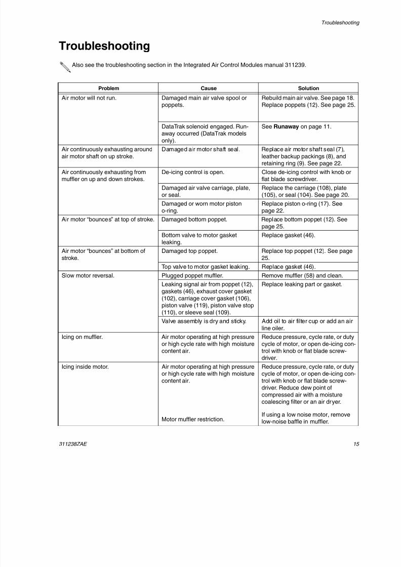
Troubleshooting
Also see the troubleshooting section in the Integrated Air Control Modules manual 311239.
Problem Cause Solution
Air motor will not run. Damaged main air valve spool orpoppets.
Rebuild main air valve. See page 18.Replace poppets (12). See page 25.
DataTrak solenoid engaged. Run-away occurred (DataTrak models
only).
See Runaway on page 11.
Air continuously exhausting around
air motor shaft on up stroke.
Damaged air motor shaft seal. Replace air motor shaft seal (7),
leather backup packings (8), andretaining ring (9). See page 22.
Air continuously exhausting from
muffler on up and down strokes.
De-icing control is open. Close de-icing control with knob or
flat blade screwdriver.
Damaged air valve carriage, plate,or seal.
Replace the carriage (108), plate(105), or seal (104). See page 20.
Damaged or worn motor pistono-ring.
Replace piston o-ring (17). Seepage 22.
Air motor “bounces” at top of stroke. Damaged bottom poppet. Replace bottom poppet (12). See
page 25.
Bottom valve to motor gasket
leaking.
Replace gasket (46).
Air motor “bounces” at bottom of
stroke.
Damaged top poppet. Replace top poppet (12). See page
25.
Top valve to motor gasket leaking. Replace gasket (46).Slow motor reversal. Plugged poppet muffler. Remove muffler (58) and clean.
Leaking signal air from poppet (12),
gaskets (46), exhaust cover gasket
(102), carriage cover gasket (106),piston valve (119), piston valve stop
(110), or sleeve seal (109).
Replace leaking part or gasket.
Valve assembly is dry and sticky. Add oil to air filter cup or add an air
line oiler.
Icing on muffler. Air motor operating at high pressure
or high cycle rate with high moisturecontent air.
Reduce pressure, cycle rate, or duty
cycle of motor, or open de-icing con-trol with knob or flat blade screw-
driver.
Icing inside motor. Air motor operating at high pressureor high cycle rate with high moisture
content air.
Motor muffler restriction.
Reduce pressure, cycle rate, or dutycycle of motor, or open de-icing con-
trol with knob or flat blade screw-driver. Reduce dew point of
compressed air with a moisturecoalescing filter or an air dryer.
If using a low noise motor, removelow-noise baffle in muffler.
8/12/2019 311238 Xtreme - Air Motor
http://slidepdf.com/reader/full/311238-xtreme-air-motor 16/46
Troubleshooting
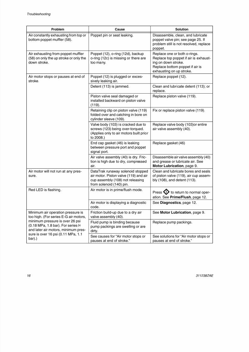
16 311238ZAE
Air constantly exhausting from top or
bottom poppet muffler (58).
Poppet pin or seat leaking. Disassemble, clean, and lubricate
poppet valve pin; see page 25. Ifproblem still is not resolved, replace
poppet.
Air exhausting from poppet muffler(58) on only the up stroke or only thedown stroke.
Poppet (12), o-ring (12d), backupo-ring (12c) is missing or there aretoo many.
Replace one or both o-rings.Replace top poppet if air is exhaust-ing on down stroke.Replace bottom poppet if air is
exhausting on up stroke.
Air motor stops or pauses at end of
stroke.
Poppet (12) is plugged or exces-
sively leaking air.
Replace poppet (12).
Detent (113) is jammed. Clean and lubricate detent (113); or
replace.
Piston valve seal damaged or
installed backward on piston valve(119).
Replace piston valve (119).
Retaining clip on piston valve (119)folded over and catching in bore on
cylinder sleeve (109).
Fix or replace piston valve (119).
Valve body (103) is cracked due to
screws (123) being over-torqued.(Applies only to air motors built priorto 2008.)
Replace valve body (103)or entire
air valve assembly (40).
End cap gasket (46) is leakingbetween pressure port and poppet
signal port.
Replace gasket (46)
Air valve assembly (40) is dry. Fric-
tion is high due to dry, compressed
air.
Disassemble air valve assembly (40)
and grease or lubricate air. See
Motor Lubrication, page 9.Air motor will not run at any pres-sure.
DataTrak runaway solenoid stoppedair motor. Piston valve (119) and air
cup assembly (108) not releasingfrom solenoid (140) pin.
Clean and lubricate bores and sealsof piston valve (119), air cup assem-
bly (108), and detent (113).
Red LED is flashing. Air motor is in prime/flush mode.Press to return to normal oper-
ation. See Prime/Flush, page 12.
Air motor is displaying a diagnosticcode.
See Diagnostics, page 12.
Minimum air operation pressure istoo high. (For series E-G air motors,
minimum pressure is over 26 psi(0.18 MPa, 1.8 bar). For series Hand later air motors, minimum pres-
sure is over 16 psi (0.11 MPa, 1.1bar).)
Friction build-up due to a dry airvalve assembly (40).
See Motor Lubrication, page 9.
Fluid pump is binding becausepump packings are swelling or aredirty.
Replace pump packings.
See causes for “Air motor stops orpauses at end of stroke.”
See solutions for “Air motor stops orpauses at end of stroke.”
Problem Cause Solution
8/12/2019 311238 Xtreme - Air Motor
http://slidepdf.com/reader/full/311238-xtreme-air-motor 17/46
Troubleshooting
311238ZAE 17
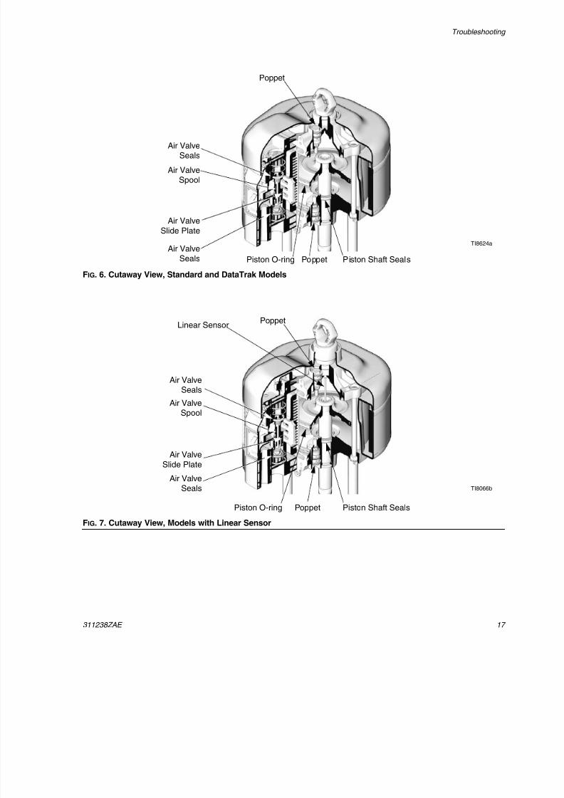
FIG. 6. Cutaway View, Standard and DataTrak Models
TI8624a
Poppet
Poppet Piston Shaft SealsPiston O-ring
Air ValveSeals
Air ValveSpool
Air Valve
Slide Plate
Air ValveSeals
FIG. 7. Cutaway View, Models with Linear Sensor
TI8066b
Poppet
Poppet Piston Shaft SealsPiston O-ring
Air ValveSeals
Air ValveSpool
Air Valve
Slide Plate
Air ValveSeals
Linear Sensor
8/12/2019 311238 Xtreme - Air Motor
http://slidepdf.com/reader/full/311238-xtreme-air-motor 18/46
Repair
18 311238ZAE
Repair
Preventive MaintenanceSchedule
The operating conditions of your particular system
determine how often maintenance is required. Establisha preventive maintenance schedule by recording whenand what kind of maintenance is needed, and then
determine a regular schedule for checking your system.
Tools Required
• Flat blade screwdriver
• Phillips screwdriver
• 3/4 in. socket wrench
• 9/16 in. socket wrench
• 3/8 in. socket wrench
• Torque wrench
• Grease
• Thread adhesive
Pressure Relief Procedure
1. Engage the trigger lock.
2. Close the bleed-type master air valve.
3. Disengage the trigger lock.
4. Hold a metal part of the gun firmly to a grounded
metal pail. Trigger the gun to relieve pressure.
5. Engage the trigger lock.
6. Open all fluid drain valves in the system, having awaste container ready to catch drainage. Leavedrain valve(s) open until you are ready to spray
again.
7. If you suspect the spray tip or hose is clogged or
that pressure has not been fully relieved after follow-ing the steps above, VERY SLOWLY loosen tipguard retaining nut or hose end coupling to relieve
pressure gradually, then loosen completely. Clearhose or tip obstruction.
Air Valve Repair
Remove the Air Valve
1. Stop the pump at the middle of its stroke. Relieve
the pressure, page 18.
2. Disconnect the air line to the motor.
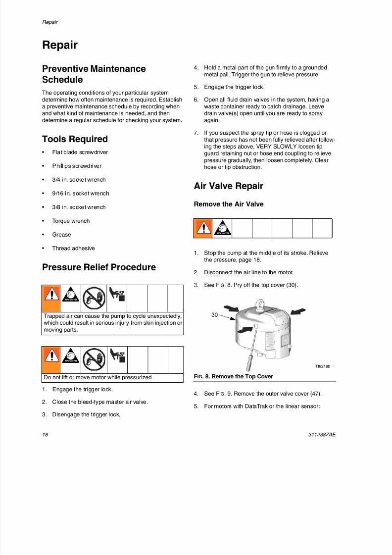
3. See FIG. 8. Pry off the top cover (30).
4. See FIG. 9. Remove the outer valve cover (47).
5. For motors with DataTrak or the linear sensor:
Trapped air can cause the pump to cycle unexpectedly,which could result in serious injury from skin injection or
moving parts.
Do not lift or move motor while pressurized. FIG. 8. Remove the Top Cover
TI8218b
30
8/12/2019 311238 Xtreme - Air Motor
http://slidepdf.com/reader/full/311238-xtreme-air-motor 19/46
Repai
311238ZAE 19
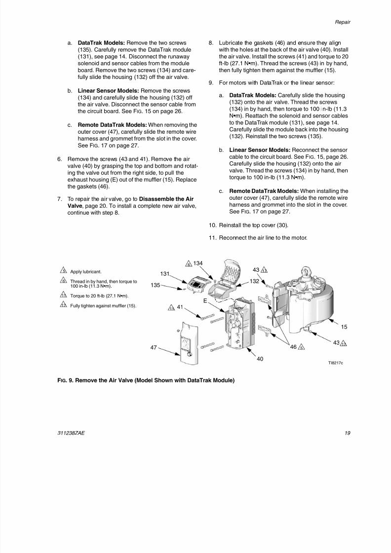
a. DataTrak Models: Remove the two screws
(135). Carefully remove the DataTrak module(131), see page 14. Disconnect the runawaysolenoid and sensor cables from the module
board. Remove the two screws (134) and care-fully slide the housing (132) off the air valve.
b. Linear Sensor Models: Remove the screws
(134) and carefully slide the housing (132) offthe air valve. Disconnect the sensor cable fromthe circuit board. See FIG. 15 on page 26.
c. Remote DataTrak Models: When removing the
outer cover (47), carefully slide the remote wireharness and grommet from the slot in the cover.
See FIG. 17 on page 27.
6. Remove the screws (43 and 41). Remove the air
valve (40) by grasping the top and bottom and rotat-
ing the valve out from the right side, to pull theexhaust housing (E) out of the muffler (15). Replacethe gaskets (46).
7. To repair the air valve, go to Disassemble the Air
Valve, page 20. To install a complete new air valve,continue with step 8.
8. Lubricate the gaskets (46) and ensure they alignwith the holes at the back of the air valve (40). Install
the air valve. Install the screws (41) and torque to 20ft-lb (27.1 N•m). Thread the screws (43) in by hand,
then fully tighten them against the muffler (15).
9. For motors with DataTrak or the linear sensor:
a. DataTrak Models: Carefully slide the housing(132) onto the air valve. Thread the screws
(134) in by hand, then torque to 100 in-lb (11.3N•m). Reattach the solenoid and sensor cables
to the DataTrak module (131), see page 14.Carefully slide the module back into the housing(132). Reinstall the two screws (135).
b. Linear Sensor Models: Reconnect the sensor
cable to the circuit board. See FIG. 15, page 26.Carefully slide the housing (132) onto the air
valve. Thread the screws (134) in by hand, thentorque to 100 in-lb (11.3 N•m).
c. Remote DataTrak Models: When installing theouter cover (47), carefully slide the remote wire
harness and grommet into the slot in the cover.See FIG. 17 on page 27.
10. Reinstall the top cover (30).
11. Reconnect the air line to the motor.
FIG. 9. Remove the Air Valve (Model Shown with DataTrak Module)
TI8217c
47
41
40
43
43
46
Apply lubricant.
Thread in by hand, then torque to100 in-lb (11.3 N•m).
Torque to 20 ft-lb (27.1 N•m).
Fully tighten against muffler (15).
5
6
11
17
17
5
11
17
132
1346
131
135
15
E
8/12/2019 311238 Xtreme - Air Motor
http://slidepdf.com/reader/full/311238-xtreme-air-motor 20/46
Repair
20 311238ZAE
Disassemble the Air Valve
1. Perform steps 1-6 under Remove the Air Valve,page 18.
2. See FIG. 11. Remove the screws (124), carriage
cover (112), spring-loaded detent (113), gasket(106), and de-icing control (145).
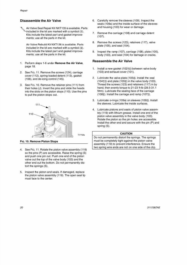
3. See FIG. 10. Remove the retainer pins (111) from
their holes (J). Invert the pins and slide the headsinto the slots on the piston stops (110). Use the pinsto pull the piston stops out.
4. See FIG. 11. Rotate the piston valve assembly (119)
so the pins (P) are accessible. Raise the spring (S)and push one pin out. Push one end of the piston
valve out the top of the valve body (103) and theother end out the bottom. Do not permanently dis-
tort the springs (S).
5. Inspect the piston and seals. If damaged, replace
the piston valve assembly (119). The open seal lipmust face to the center.
6. Carefully remove the sleeves (109). Inspect theseals (109a) and the inside surface of the sleeves
and housing (103) for wear or damage.
7. Remove the carriage (108) and carriage detent
(107).
8. Remove the screws (123), retainers (117), valveplate (105), and seal (104).
9. Inspect the ramp (107), carriage (108), plate (105),
body (103), and seal (104) for damage or cracks.
Reassemble the Air Valve
1. Install a new gasket (102†‡) between valve body(103) and exhaust cover (101).
2. Lubricate the valve plate (105‡). Install the seal(104†‡) and plate (105‡) in the valve body (103).
Thread the screws (123) and retainers (117) in byhand, then evenly torque to 21-23 ft-lb (28.5-31.1N•m). Lubricate the sealing face of the carriage
(108‡). Install the carriage and ramp (107‡).
3. Lubricate o-rings (109a) on sleeves (109‡). Installthe sleeves. Lubricate the inside surfaces.
4. Lubricate pistons and seals of piston valve assem-
bly (119) with lithium grease. Install one end of thepiston valve assembly in the valve body (103).
Rotate the piston so the pin holes are accessible.Install the other end and secure with the pin (P) and
spring (S).
Air Valve Seal Repair Kit NXT135 is available. Partsincluded in the kit are marked with a symbol (†).Kits include the latest part and gasket improve-
ments; use all the parts in the kit.
Air Valve Rebuild Kit NXT136 is available. Partsincluded in the kit are marked with a symbol (‡).
Kits include the latest part and gasket improve-ments; use all the parts in the kit.
FIG. 10. Remove Piston Stops
TI7758a
111
J
110
CAUTION
Do not permanently distort the springs. The springs
must be completely tight against the piston valveassembly (119) to prevent interference. Ensure the
two spring wire ends are not on one side of the clip.
8/12/2019 311238 Xtreme - Air Motor
http://slidepdf.com/reader/full/311238-xtreme-air-motor 21/46
Repai
311238ZAE 2
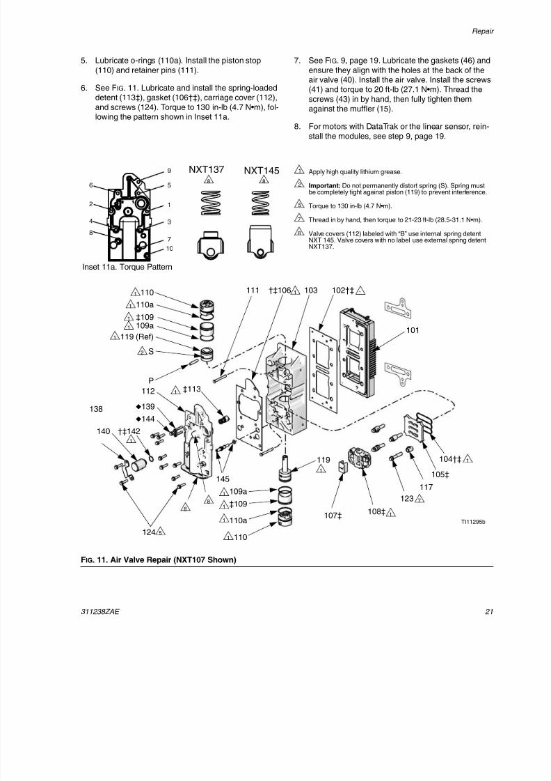
5. Lubricate o-rings (110a). Install the piston stop
(110) and retainer pins (111).
6. See FIG. 11. Lubricate and install the spring-loadeddetent (113‡), gasket (106†‡), carriage cover (112),
and screws (124). Torque to 130 in-lb (4.7 N•m), fol-lowing the pattern shown in Inset 11a.
7. See FIG. 9, page 19. Lubricate the gaskets (46) and
ensure they align with the holes at the back of theair valve (40). Install the air valve. Install the screws(41) and torque to 20 ft-lb (27.1 N•m). Thread the
screws (43) in by hand, then fully tighten themagainst the muffler (15).
8. For motors with DataTrak or the linear sensor, rein-
stall the modules, see step 9, page 19.
FIG. 11. Air Valve Repair (NXT107 Shown)
Apply high quality lithium grease.
Important: Do not permanently distort spring (S). Spring mustbe completely tight against piston (119) to prevent interference.
Torque to 130 in-lb (4.7 N•m).
Thread in by hand, then torque to 21-23 ft-lb (28.5-31.1 N•m).
Valve covers (112) labeled with “B” use internal spring detentNXT 145. Valve covers with no label use external spring detent
NXT137.
1
2
5
7
8
7
5
S
1
1
2
P
TI11295b
102†‡
101
104†‡
105‡
117
123
108‡107‡
‡113
124
138
140 †‡142
112
†‡106111 103
145
139
144
‡109
‡109
110
119
110
119 (Ref)
110a
109a
109a
110a
1
1
1
1
1
1
1
1
1
1
1
1
1
1
8
8
NXT137 NXT1458 8
6
2
4
8
9
5
1
3
7
10
Inset 11a. Torque Pattern
8/12/2019 311238 Xtreme - Air Motor
http://slidepdf.com/reader/full/311238-xtreme-air-motor 22/46
Repair
22 311238ZAE
Cylinder and Piston Repair
Disassemble the Air Motor
1. Stop the pump at the middle of its stroke. Relievethe pressure, page 18.
2. Disconnect the air line to the motor.
3. See FIG. 8 on page 18. Pry off the top cover (30).
4. For motors with DataTrak or the linear sensor:
a. DataTrak Models: Remove the two screws(135). Carefully remove the DataTrak module
(131), see page 14. Disconnect the runawaysolenoid and sensor cables from the moduleboard. Remove the two screws (134) and care-
fully slide the housing (132) off the air valve.
b. Linear Sensor Models: Remove the screws(134) and carefully slide the housing (132) off
the air valve. Disconnect the sensor cable fromthe circuit board. See FIG. 15 on page 26.
5. Remove the outer valve cover (47). See FIG. 12.
6. Remove the four screws (43) and the muffler (15).
7. Remove the top two air valve screws (41). Loosen
but do not remove the bottom two screws (41). Tiltthe air valve (40) to make disassembly easier.
8. Remove the tie bolts (13). Using a rubber mallet, hit
the underside of the top cap (1) to separate. Lift thetop cap off the motor.
9. Disconnect the air motor from the lower (see your
separate pump manual). Leave the piston shaftadapter (A) attached to the shaft (S).
10. Push the piston assembly (4) out the top of the cyl-
inder (2).
11. Inspect the piston o-ring (17). Check the piston (4)
and piston shaft (S) for scoring or damage. Thereplacement piston (4) includes the piston, shaft (S),adapter (A), and bumper (10).
12. Remove the cylinder (2). Check the inner surface for
scoring or other damage. Replace if damaged.
13. Remove the bumper (59), retaining ring (9), backuppackings (8), and v-packing (7) from the bottomcover (3). Inspect these parts for wear or damage.
Inspect the bearing (B) in place (slight scoring isacceptable). If the bearing is damaged, replace the
bottom cover (3).
Air Motor Seal Repair Kits are available. See the
parts lists on pages 30, 32, and 34 for the correctkit for your size motor. Parts included in the kits are
marked with an asterisk (*). For the best results,
use all the parts in the kit.
8/12/2019 311238 Xtreme - Air Motor
http://slidepdf.com/reader/full/311238-xtreme-air-motor 23/46
Repai
311238ZAE 23
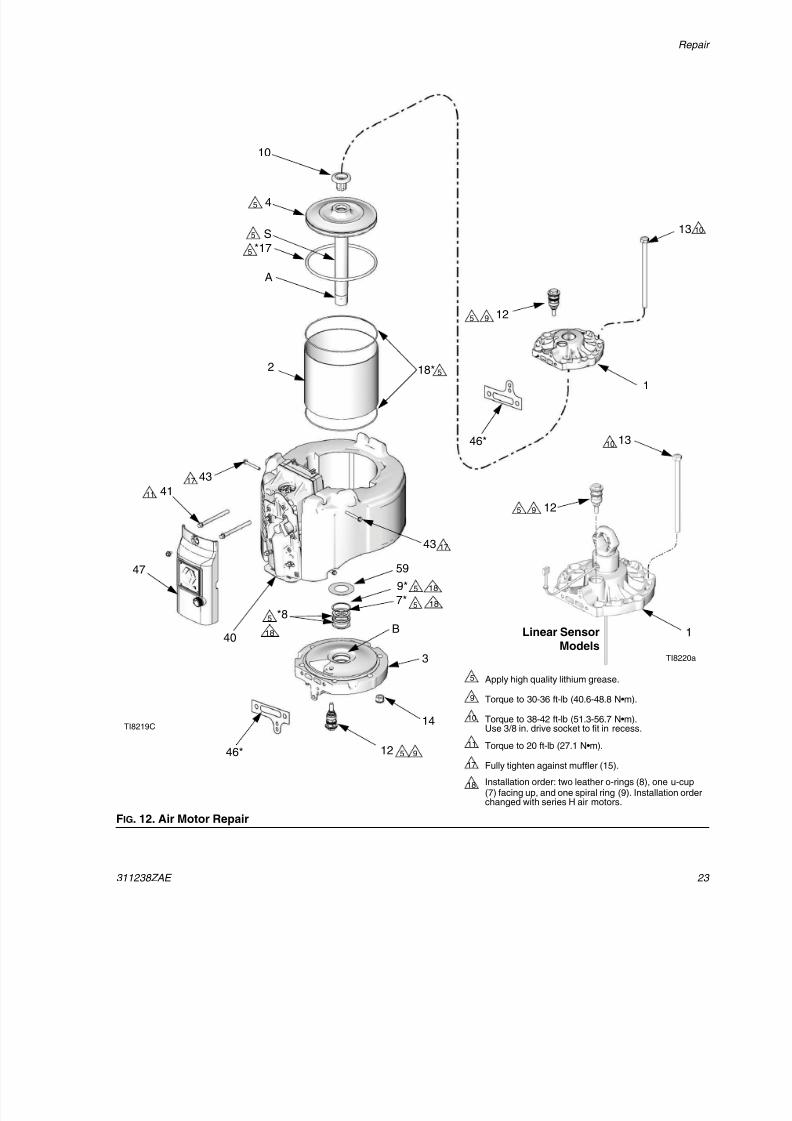
FIG. 12. Air Motor Repair
12
1
18*
47
12
3
14
7*
9*
*8
*17
4
10
13
2
43
41
40
TI8219C
Apply high quality lithium grease.
Torque to 30-36 ft-lb (40.6-48.8 N•m).
Torque to 38-42 ft-lb (51.3-56.7 N•m).Use 3/8 in. drive socket to fit in recess.
Torque to 20 ft-lb (27.1 N•m).
Fully tighten against muffler (15).
Installation order: two leather o-rings (8), one u-cup(7) facing up, and one spiral ring (9). Installation orderchanged with series H air motors.
5
9
10
11
17
18
5 9
11
17
5
5
5
5
5
5 9
S
B
A
4317
59
12
1
13
5
10
9
TI8220a
Linear Sensor
Models
10
5
5
18
18
18
46*
46*
8/12/2019 311238 Xtreme - Air Motor
http://slidepdf.com/reader/full/311238-xtreme-air-motor 24/46
Repair
24 311238ZAE
Reassemble Air Motor
1. See FIG. 12. Install two backup packings (8*), and
then v-packing (7*) with the lips facing up. Theninstall the retaining ring (9*) in the bottom cover (3).
Lubricate the packings. Install the bumper (59).
2. Install the o-ring (17*) on the piston (4). Ensure the
piston bumper (10) is in place.
3. Install the piston assembly on the bottom cover (3),
carefully sliding the adapter (A) and shaft (S)through the packings.
4. Grease the inside of the cylinder (2). Place the cylin-
der (2) over the piston (4). Be careful not to damagethe o-ring (17*). Slowly work the o-ring into the
groove, compressing it until the cylinder slides over.
5. Carefully place the top cap on the cylinder (2) so theflat edge aligns with the flat edge of the bottom
cover (3). Install the tie bolts (13) hand tight.
6. Using new gaskets (46), reinstall the valve assemblywith the top two air valve screws (41) and torque to
20 ft-lb (27.1 N•m). Install the bottom two air valvescrews (41) tight to align the end caps (1) and bot-
tom cover (3). Then loosen the two bottom screws(41).
7. Torque end cap tie bolts (13) evenly to 38-42 ft-lb
(51.3-56.7 N•m).
8. Retighten the bottom two air valve screws (41) andtorque to 20 ft-lb (27.1 N•m).
9. Reconnect the air motor to the lower (see your sep-
arate pump manual).
10. Reinstall the muffler (15). Fully tighten the screws(43) against the muffler.
11. Reinstall the outer valve cover (47).
12. For motors with DataTrak or the linear sensor:
a. DataTrak Models: Carefully slide the housing(132) onto the air valve. Thread the screws
(134) in by hand, then torque to 100 in-lb (11.3N•m). Reattach the solenoid and sensor cables
to the DataTrak module (131), see page 14.Carefully slide the module back into the housing(132). Reinstall the two screws (135).
b. Linear Sensor Models: Reconnect the sensor
cable to the circuit board. See FIG. 15, page 26.Carefully slide the housing (132) onto the air
valve. Thread the screws (134) in by hand, thentorque to 100 in-lb (11.3 N•m).
13. Reinstall the top cover (30).
14. Reconnect the air line to the motor.
Prior to series H air motors the u-cup (7) was
installed between the leather packings (8).
It is normal for the o-ring (17*) to seem too large.
It is normal for the o-ring (17*) to seem too large tofit into the cylinder.
See Accessories, page 40, for a list of availableadapters to connect the NXT motor to various
Graco lowers.
8/12/2019 311238 Xtreme - Air Motor
http://slidepdf.com/reader/full/311238-xtreme-air-motor 25/46
Repai
311238ZAE 25
Poppet Repair
1. Stop the pump at the middle of its stroke. Relievethe pressure, page 9.
2. Disconnect the air line to the motor.
3. See FIG. 8 on page 18. Pry off the top cover (30).
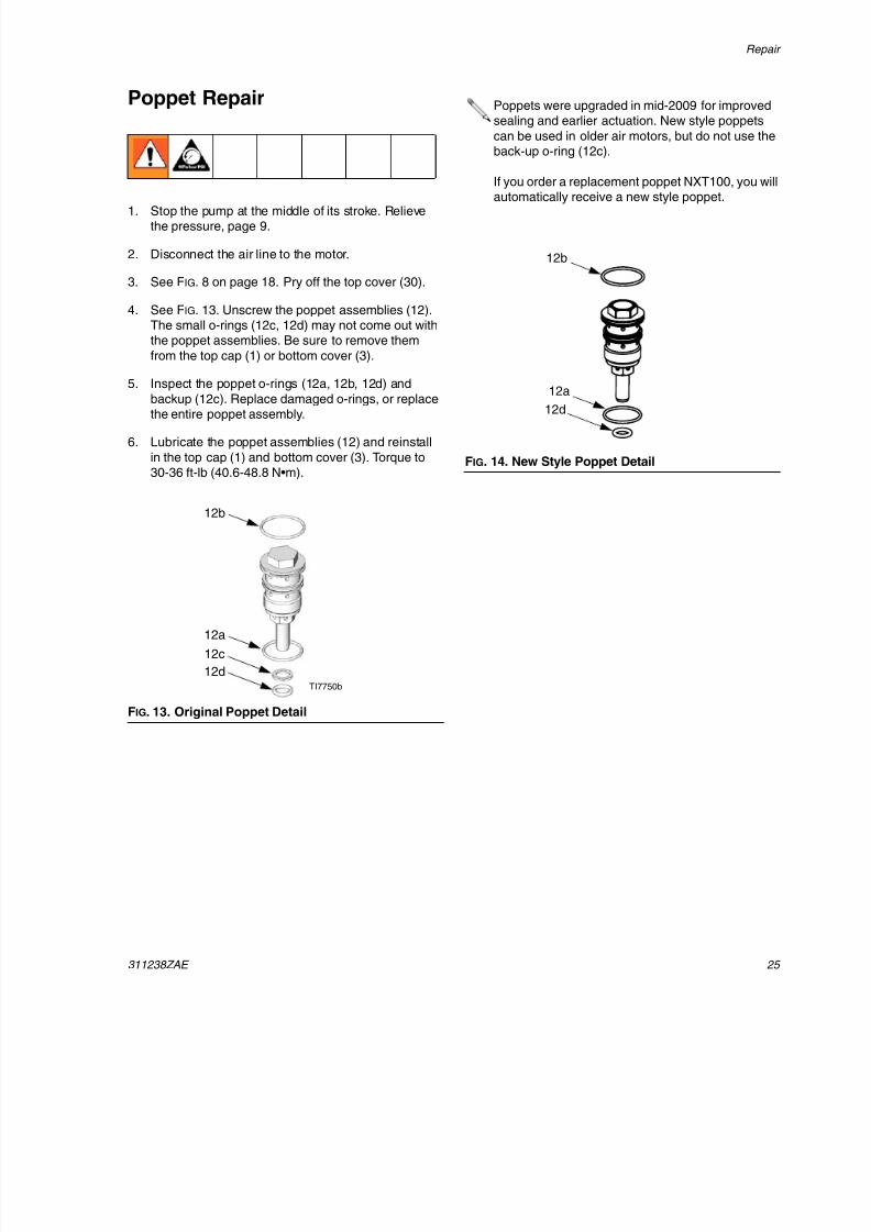
4. See FIG. 13. Unscrew the poppet assemblies (12).The small o-rings (12c, 12d) may not come out withthe poppet assemblies. Be sure to remove them
from the top cap (1) or bottom cover (3).
5. Inspect the poppet o-rings (12a, 12b, 12d) andbackup (12c). Replace damaged o-rings, or replacethe entire poppet assembly.
6. Lubricate the poppet assemblies (12) and reinstall
in the top cap (1) and bottom cover (3). Torque to30-36 ft-lb (40.6-48.8 N•m).
FIG. 13. Original Poppet Detail
TI7750b
12a
12b
12c
12d
Poppets were upgraded in mid-2009 for improvedsealing and earlier actuation. New style poppets
can be used in older air motors, but do not use theback-up o-ring (12c).
If you order a replacement poppet NXT100, you wil
automatically receive a new style poppet.
FIG. 14. New Style Poppet Detail
12a
12b
12d
8/12/2019 311238 Xtreme - Air Motor
http://slidepdf.com/reader/full/311238-xtreme-air-motor 26/46
Repair
26 311238ZAE
Replace the Linear Sensor (ifpresent)
1. Stop the pump at the middle of its stroke. Relievethe pressure, page 9.
2. Disconnect the air line to the motor.
3. See FIG. 8 on page 18. Pry off the top cover (30).
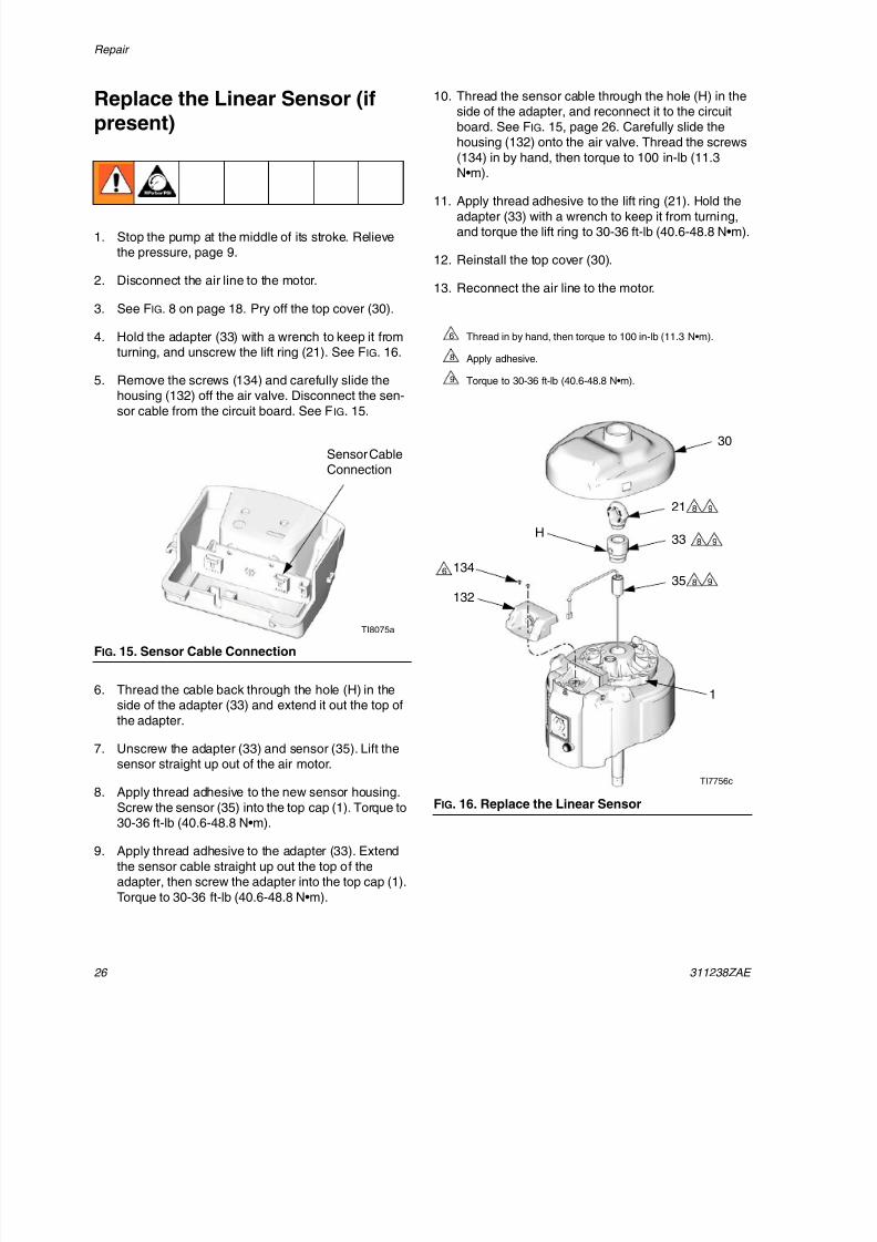
4. Hold the adapter (33) with a wrench to keep it fromturning, and unscrew the lift ring (21). See FIG. 16.
5. Remove the screws (134) and carefully slide the
housing (132) off the air valve. Disconnect the sen-sor cable from the circuit board. See FIG. 15.
6. Thread the cable back through the hole (H) in theside of the adapter (33) and extend it out the top of
the adapter.
7. Unscrew the adapter (33) and sensor (35). Lift thesensor straight up out of the air motor.
8. Apply thread adhesive to the new sensor housing.
Screw the sensor (35) into the top cap (1). Torque to30-36 ft-lb (40.6-48.8 N•m).
9. Apply thread adhesive to the adapter (33). Extend
the sensor cable straight up out the top of theadapter, then screw the adapter into the top cap (1).
Torque to 30-36 ft-lb (40.6-48.8 N•m).
10. Thread the sensor cable through the hole (H) in theside of the adapter, and reconnect it to the circuit
board. See FIG. 15, page 26. Carefully slide thehousing (132) onto the air valve. Thread the screws
(134) in by hand, then torque to 100 in-lb (11.3N•m).
11. Apply thread adhesive to the lift ring (21). Hold the
adapter (33) with a wrench to keep it from turning,and torque the lift ring to 30-36 ft-lb (40.6-48.8 N•m).
12. Reinstall the top cover (30).
13. Reconnect the air line to the motor.
FIG. 15. Sensor Cable Connection
Sensor CableConnection
TI8075a
FIG. 16. Replace the Linear Sensor
TI7756c
21
33
35 8
8 9
Thread in by hand, then torque to 100 in-lb (11.3 N•m).
Apply adhesive.
Torque to 30-36 ft-lb (40.6-48.8 N•m).
6
8
9
H
1
30
132
1346
8 9
9
8/12/2019 311238 Xtreme - Air Motor
http://slidepdf.com/reader/full/311238-xtreme-air-motor 27/46
Repai
311238ZAE 27
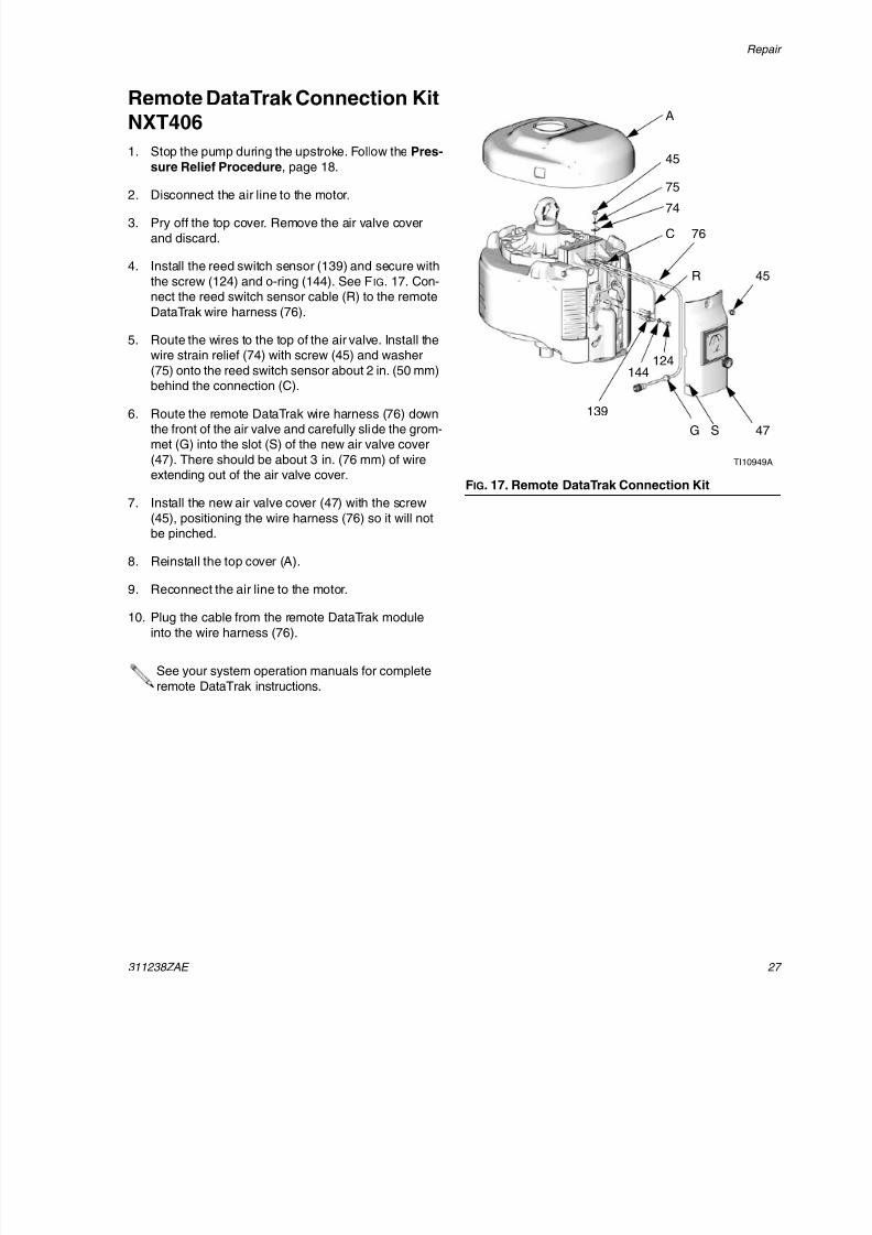
Remote DataTrak Connection KitNXT406
1. Stop the pump during the upstroke. Follow the Pres-
sure Relief Procedure, page 18.
2. Disconnect the air line to the motor.
3. Pry off the top cover. Remove the air valve cover
and discard.
4. Install the reed switch sensor (139) and secure with
the screw (124) and o-ring (144). See FIG. 17. Con-nect the reed switch sensor cable (R) to the remote
DataTrak wire harness (76).
5. Route the wires to the top of the air valve. Install thewire strain relief (74) with screw (45) and washer
(75) onto the reed switch sensor about 2 in. (50 mm)
behind the connection (C).
6. Route the remote DataTrak wire harness (76) downthe front of the air valve and carefully slide the grom-met (G) into the slot (S) of the new air valve cover
(47). There should be about 3 in. (76 mm) of wireextending out of the air valve cover.
7. Install the new air valve cover (47) with the screw
(45), positioning the wire harness (76) so it will notbe pinched.
8. Reinstall the top cover (A).
9. Reconnect the air line to the motor.
10. Plug the cable from the remote DataTrak module
into the wire harness (76).
See your system operation manuals for complete
remote DataTrak instructions.
FIG. 17. Remote DataTrak Connection Kit
A
TI10949A
76
74
75
47G S
45
139
124144
R
C
45
8/12/2019 311238 Xtreme - Air Motor
http://slidepdf.com/reader/full/311238-xtreme-air-motor 28/46
Parts
28 311238ZAE
Parts
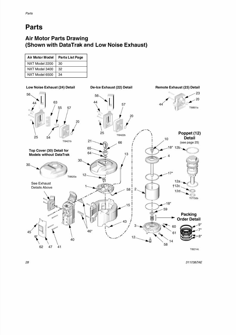
Air Motor Parts Drawing(Shown with DataTrak and Low Noise Exhaust)
Air Motor Model Parts List Page
NXT Model 2200 30
NXT Model 3400 32
NXT Model 6500 34
TI7750b
Poppet (12)Detail
(see page 25)
12a
12b
12d
30
21
12
1
56
47
12
3
14
61
60
18*
7*
9*
8*
17*
4
10
13
2
15
43
41
40
46*
58
58
TI8620a
59
18*
45
Top Cover (30) Detail forModels without DataTrak
30
TI8214d62
20
44
23
TI8801a
Remote Exhaust (23) Detail
See Exhaust
Details Above
De-Ice Exhaust (22) DetailLow Noise Exhaust (24) Detail
44
20
57
56
55
54
63
56
44
20
25
57
TI9422b
TI9421b
25
†12c
PackingOrder Detail}
66
65
64
8/12/2019 311238 Xtreme - Air Motor
http://slidepdf.com/reader/full/311238-xtreme-air-motor 29/46
Parts
311238ZAE 29
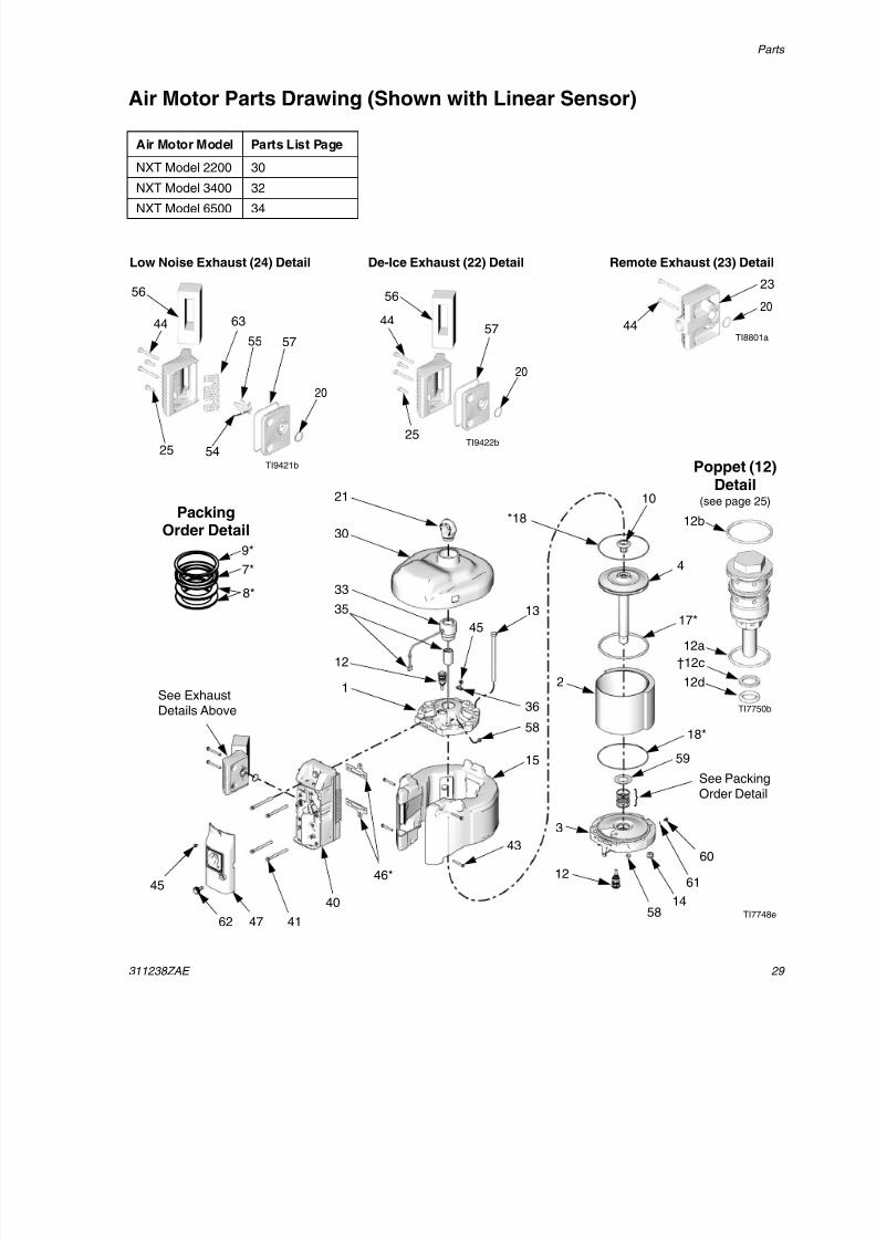
Air Motor Parts Drawing (Shown with Linear Sensor)
Air Motor Model Parts List Page
NXT Model 2200 30
NXT Model 3400 32NXT Model 6500 34
TI7750b
112a
12b
112d
30
21
33
35
12
1
*18
12
3
14
61
60
18*
17*
4
10
45
13
2
15
43
41
40
46*
36
58
58
TI7748e
59
47
45
62
20
44
23
TI8801a
Remote Exhaust (23) DetailDe-Ice Exhaust (22) DetailLow Noise Exhaust (24) Detail
See ExhaustDetails Above
44
20
57
56
55
54
63
56
44
20
25
57
TI9422b
TI9421b
25
7*
9*
8*
†12c
PackingOrder Detail
}See PackingOrder Detail
Poppet (12)Detail
(see page 25)
8/12/2019 311238 Xtreme - Air Motor
http://slidepdf.com/reader/full/311238-xtreme-air-motor 30/46
Parts
30 311238ZAE
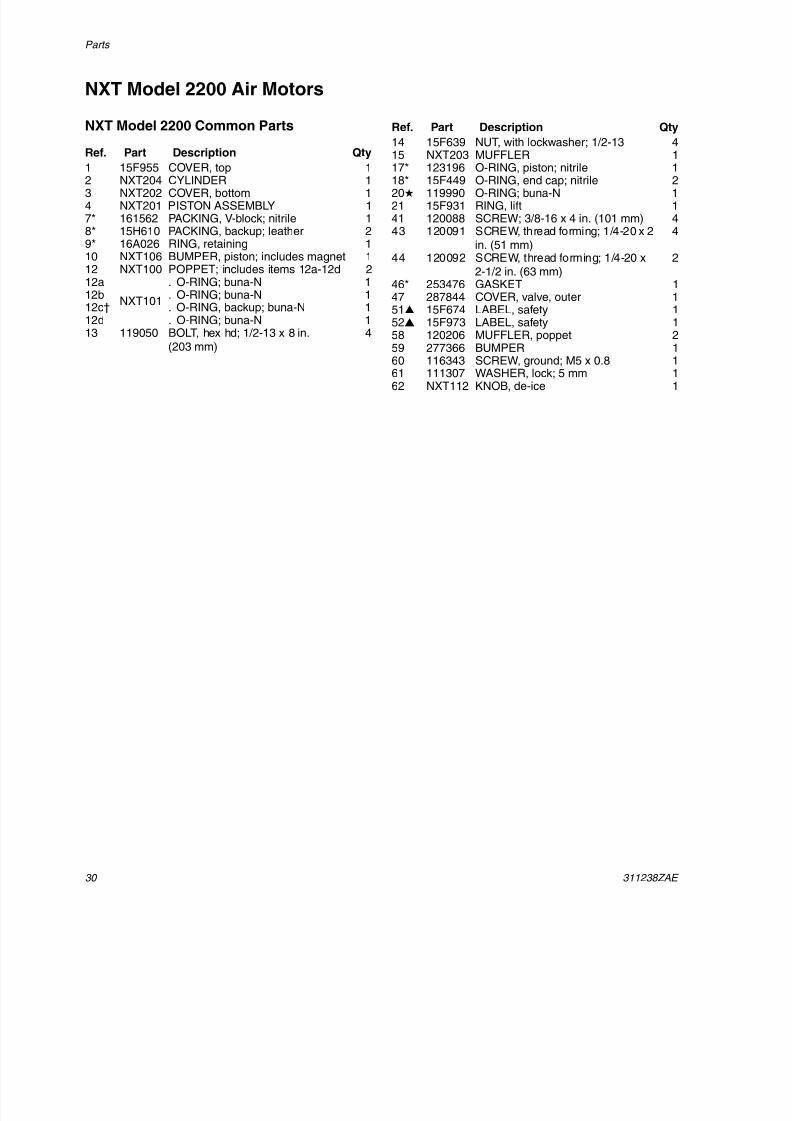
NXT Model 2200 Air Motors
NXT Model 2200 Common Parts
Ref. Part Description Qty
1 15F955 COVER, top 12 NXT204 CYLINDER 13 NXT202 COVER, bottom 14 NXT201 PISTON ASSEMBLY 17* 161562 PACKING, V-block; nitrile 18* 15H610 PACKING, backup; leather 29* 16A026 RING, retaining 110 NXT106 BUMPER, piston; includes magnet 112 NXT100 POPPET; includes items 12a-12d 212a
NXT101
. O-RING; buna-N 112b . O-RING; buna-N 112c† . O-RING, backup; buna-N 112d . O-RING; buna-N 113 119050 BOLT, hex hd; 1/2-13 x 8 in.
(203 mm)
4
14 15F639 NUT, with lockwasher; 1/2-13 415 NXT203 MUFFLER 117* 123196 O-RING, piston; nitrile 118* 15F449 O-RING, end cap; nitrile 220 119990 O-RING; buna-N 121 15F931 RING, lift 141 120088 SCREW; 3/8-16 x 4 in. (101 mm) 443 120091 SCREW, thread forming; 1/4-20 x 2
in. (51 mm)4
44 120092 SCREW, thread forming; 1/4-20 x2-1/2 in. (63 mm)
2
46* 253476 GASKET 147 287844 COVER, valve, outer 151 15F674 LABEL, safety 152 15F973 LABEL, safety 158 120206 MUFFLER, poppet 2
59 277366 BUMPER 160 116343 SCREW, ground; M5 x 0.8 161 111307 WASHER, lock; 5 mm 162 NXT112 KNOB, de-ice 1
Ref. Part Description Qty
8/12/2019 311238 Xtreme - Air Motor
http://slidepdf.com/reader/full/311238-xtreme-air-motor 31/46
Parts
311238ZAE 3
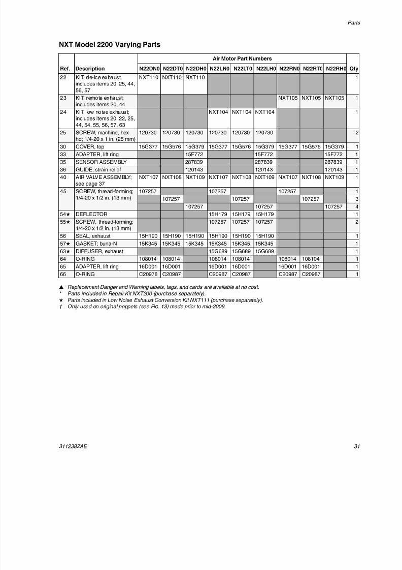
NXT Model 2200 Varying Parts
Replacement Danger and Warning labels, tags, and cards are available at no cost.
* Parts included in Repair Kit NXT200 (purchase separately).
Parts included in Low Noise Exhaust Conversion Kit NXT111 (purchase separately).
† Only used on original poppets (see F IG . 13) made prior to mid-2009.
Ref. Description
Air Motor Part Numbers
QtyN22DN0 N22DT0 N22DH0 N22LN0 N22LT0 N22LH0 N22RN0 N22RT0 N22RH0
22 KIT, de-ice exhaust,
includes items 20, 25, 44,
56, 57
NXT110 NXT110 NXT110 1
23 KIT, remote exhaust;
includes items 20, 44
NXT105 NXT105 NXT105 1
24 KIT, low noise exhaust;
includes items 20, 22, 25,
44, 54, 55, 56, 57, 63
NXT104 NXT104 NXT104 1
25 SCREW, machine, hex
hd; 1/4-20 x 1 in. (25 mm)
120730 120730 120730 120730 120730 120730 2
30 COVER, top 15G377 15G576 15G379 15G377 15G576 15G379 15G377 15G576 15G379 1
33 ADAPTER, lift ring 15F772 15F772 15F772 1
35 SENSOR ASSEMBLY 287839 287839 287839 1
36 GUIDE, strain relief 120143 120143 120143 1
40 AIR VALVE ASSEMBLY;see page 37 NXT107 NXT108 NXT109 NXT107 NXT108 NXT109 NXT107 NXT108 NXT109 1
45 SCREW, thread-forming;
1/4-20 x 1/2 in. (13 mm)
107257 107257 107257 1
107257 107257 107257 3
107257 107257 107257 4
54 DEFLECTOR 15H179 15H179 15H179 1
55 SCREW, thread-forming;
1/4-20 x 1/2 in. (13 mm)
107257 107257 107257 2
56 SEAL, exhaust 15H190 15H190 15H190 15H190 15H190 15H190 1
57 GASKET; buna-N 15K345 15K345 15K345 15K345 15K345 15K345 1
63 DIFFUSER, exhaust 15G689 15G689 15G689 1
64 O-RING 108014 108014 108014 108014 108014 108104 1
65 ADAPTER, lift ring 16D001 16D001 16D001 16D001 16D001 16D001 166 O-RING C20978 C20987 C20987 C20987 C20987 C20987 1

8/12/2019 311238 Xtreme - Air Motor
http://slidepdf.com/reader/full/311238-xtreme-air-motor 32/46
Parts
32 311238ZAE
NXT Model 3400 Air Motors
NXT Model 3400 Common Parts
Ref. Part Description Qty
1 15F954 COVER, top 12 NXT304 CYLINDER 13 NXT302 COVER, bottom 14 NXT301 PISTON ASSEMBLY 17* 161562 PACKING, V-block; nitrile 18* 15H610 PACKING, backup; leather 29* 16A026 RING, retaining 110 NXT106 BUMPER, piston; includes magnet 112 NXT100 POPPET; includes items 12a-12d 212a
NXT101
. O-RING; buna-N 112b . O-RING; buna-N 112c† . O-RING, backup; buna-N 112d . O-RING; buna-N 113 119050 BOLT, hex hd; 1/2-13 x 8 in.
(203 mm)
6
14 15F639 NUT, with lockwasher; 1/2-13 615 NXT303 MUFFLER 117* 122434 O-RING, piston; nitrile 118* 15F449 O-RING, end cap; nitrile 220 119990 O-RING; buna-N 121 15F931 RING, lift 141 120088 SCREW; 3/8-16 x 4 in. (101 mm) 443 120091 SCREW, thread forming; 1/4-20 x 2
in. (51 mm)4
44 120092 SCREW, thread forming; 1/4-20 x2-1/2 in. (63 mm)
2
46* 253476 GASKET 147 287844 COVER, valve, outer 151 15F674 LABEL, safety 152 15F973 LABEL, safety 158 120206 MUFFLER, poppet 2
59 277366 BUMPER 160 116343 SCREW, ground; M5 x 0.8 161 111307 WASHER, lock; 5 mm 162 NXT112 KNOB, de-ice 1
Ref. Part Description Qty
8/12/2019 311238 Xtreme - Air Motor
http://slidepdf.com/reader/full/311238-xtreme-air-motor 33/46
Parts
311238ZAE 33
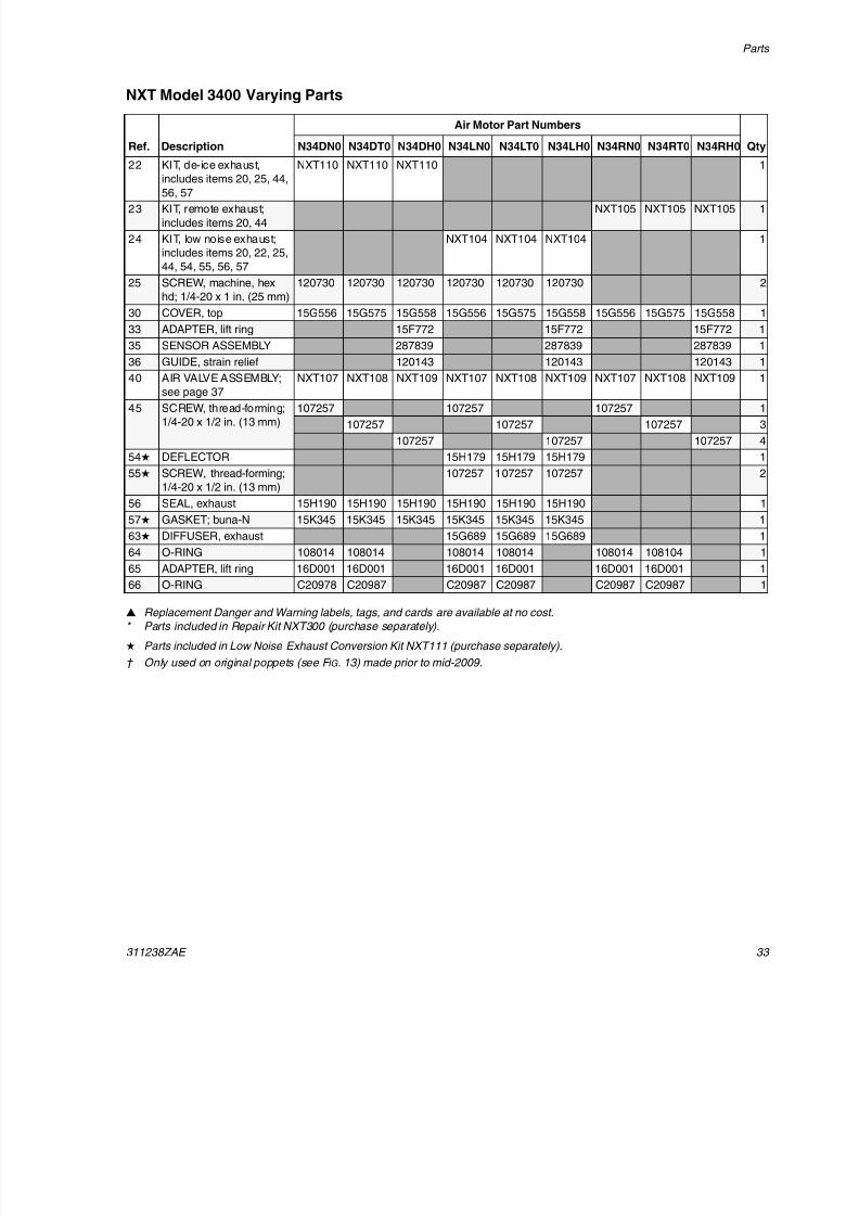
NXT Model 3400 Varying Parts
Replacement Danger and Warning labels, tags, and cards are available at no cost.
* Parts included in Repair Kit NXT300 (purchase separately).
Parts included in Low Noise Exhaust Conversion Kit NXT111 (purchase separately).
† Only used on original poppets (see F IG . 13) made prior to mid-2009.
Ref. Description
Air Motor Part Numbers
QtyN34DN0 N34DT0 N34DH0 N34LN0 N34LT0 N34LH0 N34RN0 N34RT0 N34RH0
22 KIT, de-ice exhaust,
includes items 20, 25, 44,
56, 57
NXT110 NXT110 NXT110 1
23 KIT, remote exhaust;
includes items 20, 44
NXT105 NXT105 NXT105 1
24 KIT, low noise exhaust;
includes items 20, 22, 25,
44, 54, 55, 56, 57
NXT104 NXT104 NXT104 1
25 SCREW, machine, hex
hd; 1/4-20 x 1 in. (25 mm)
120730 120730 120730 120730 120730 120730 2
30 COVER, top 15G556 15G575 15G558 15G556 15G575 15G558 15G556 15G575 15G558 1
33 ADAPTER, lift ring 15F772 15F772 15F772 1
35 SENSOR ASSEMBLY 287839 287839 287839 1
36 GUIDE, strain relief 120143 120143 120143 1
40 AIR VALVE ASSEMBLY;see page 37 NXT107 NXT108 NXT109 NXT107 NXT108 NXT109 NXT107 NXT108 NXT109 1
45 SCREW, thread-forming;
1/4-20 x 1/2 in. (13 mm)
107257 107257 107257 1
107257 107257 107257 3
107257 107257 107257 4
54 DEFLECTOR 15H179 15H179 15H179 1
55 SCREW, thread-forming;
1/4-20 x 1/2 in. (13 mm)
107257 107257 107257 2
56 SEAL, exhaust 15H190 15H190 15H190 15H190 15H190 15H190 1
57 GASKET; buna-N 15K345 15K345 15K345 15K345 15K345 15K345 1
63 DIFFUSER, exhaust 15G689 15G689 15G689 1
64 O-RING 108014 108014 108014 108014 108014 108104 1
65 ADAPTER, lift ring 16D001 16D001 16D001 16D001 16D001 16D001 166 O-RING C20978 C20987 C20987 C20987 C20987 C20987 1
8/12/2019 311238 Xtreme - Air Motor
http://slidepdf.com/reader/full/311238-xtreme-air-motor 34/46
Parts
34 311238ZAE
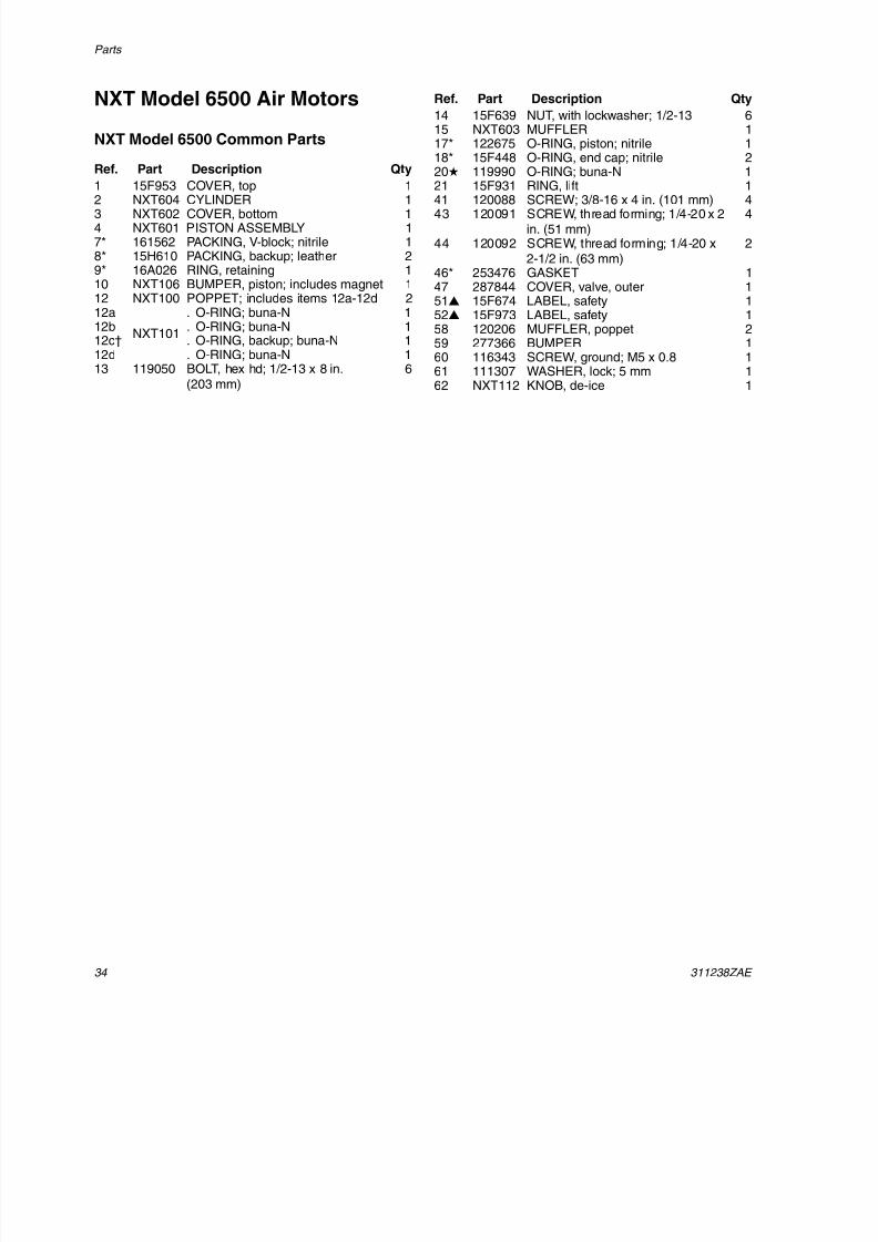
NXT Model 6500 Air Motors
NXT Model 6500 Common Parts
Ref. Part Description Qty
1 15F953 COVER, top 12 NXT604 CYLINDER 13 NXT602 COVER, bottom 14 NXT601 PISTON ASSEMBLY 17* 161562 PACKING, V-block; nitrile 18* 15H610 PACKING, backup; leather 29* 16A026 RING, retaining 110 NXT106 BUMPER, piston; includes magnet 112 NXT100 POPPET; includes items 12a-12d 212a
NXT101
. O-RING; buna-N 112b . O-RING; buna-N 112c† . O-RING, backup; buna-N 112d . O-RING; buna-N 113 119050 BOLT, hex hd; 1/2-13 x 8 in.
(203 mm)
6
14 15F639 NUT, with lockwasher; 1/2-13 615 NXT603 MUFFLER 117* 122675 O-RING, piston; nitrile 118* 15F448 O-RING, end cap; nitrile 220 119990 O-RING; buna-N 121 15F931 RING, lift 141 120088 SCREW; 3/8-16 x 4 in. (101 mm) 443 120091 SCREW, thread forming; 1/4-20 x 2
in. (51 mm)4
44 120092 SCREW, thread forming; 1/4-20 x2-1/2 in. (63 mm)
2
46* 253476 GASKET 147 287844 COVER, valve, outer 151 15F674 LABEL, safety 152 15F973 LABEL, safety 158 120206 MUFFLER, poppet 259 277366 BUMPER 160 116343 SCREW, ground; M5 x 0.8 161 111307 WASHER, lock; 5 mm 1
62 NXT112 KNOB, de-ice 1
Ref. Part Description Qty
8/12/2019 311238 Xtreme - Air Motor
http://slidepdf.com/reader/full/311238-xtreme-air-motor 35/46
Parts
311238ZAE 35
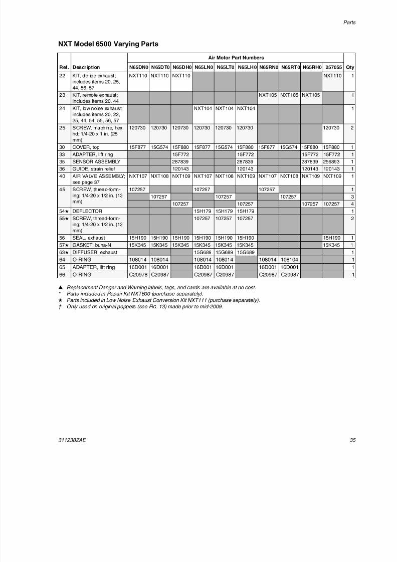
NXT Model 6500 Varying Parts
Replacement Danger and Warning labels, tags, and cards are available at no cost.
* Parts included in Repair Kit NXT600 (purchase separately).
Parts included in Low Noise Exhaust Conversion Kit NXT111 (purchase separately).
† Only used on original poppets (see F IG . 13) made prior to mid-2009.
Ref. Description
Air Motor Part Numbers
QtyN65DN0 N65DT0 N65DH0 N65LN0 N65LT0 N65LH0 N65RN0 N65RT0 N65RH0 257055
22 KIT, de-ice exhaust,
includes items 20, 25,
44, 56, 57
NXT110 NXT110 NXT110 NXT110 1
23 KIT, remote exhaust;
includes items 20, 44
NXT105 NXT105 NXT105 1
24 KIT, low noise exhaust;
includes items 20, 22,
25, 44, 54, 55, 56, 57
NXT104 NXT104 NXT104 1
25 SCREW, machine, hex
hd; 1/4-20 x 1 in. (25
mm)
120730 120730 120730 120730 120730 120730 120730 2
30 COVER, top 15F877 15G574 15F880 15F877 15G574 15F880 15F877 15G574 15F880 15F880 1
33 ADAPTER, lift ring 15F772 15F772 15F772 15F772 1
35 SENSOR ASSEMBLY 287839 287839 287839 256893 1
36 GUIDE, strain relief 120143 120143 120143 120143 1
40 AIR VALVE ASSEMBLY;see page 37
NXT107 NXT108 NXT109 NXT107 NXT108 NXT109 NXT107 NXT108 NXT109 NXT109 1
45 SCREW, thread-form-
ing; 1/4-20 x 1/2 in. (13
mm)
107257 107257 107257 1
107257 107257 107257 3
107257 107257 107257 107257 4
54 DEFLECTOR 15H179 15H179 15H179 1
55 SCREW, thread-form-
ing; 1/4-20 x 1/2 in. (13
mm)
107257 107257 107257 2
56 SEAL, exhaust 15H190 15H190 15H190 15H190 15H190 15H190 15H190 1
57 GASKET; buna-N 15K345 15K345 15K345 15K345 15K345 15K345 15K345 1
63 DIFFUSER, exhaust 15G689 15G689 15G689 1
64 O-RING 108014 108014 108014 108014 108014 108104 1
65 ADAPTER, lift ring 16D001 16D001 16D001 16D001 16D001 16D001 1
66 O-RING C20978 C20987 C20987 C20987 C20987 C20987 1
8/12/2019 311238 Xtreme - Air Motor
http://slidepdf.com/reader/full/311238-xtreme-air-motor 36/46
Parts
36 311238ZAE
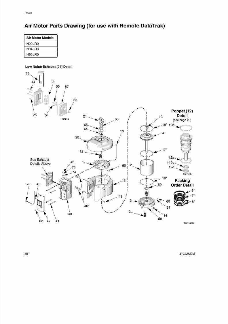
Air Motor Parts Drawing (for use with Remote DataTrak)
Air Motor Models
N22LR0
N34LR0N65LR0
TI7750b
12a
12b
12d
30
21
12
1
47
12
3
14
61
60
18*
17*
4
10
13
2
15
43
41
40
46*
58
58
59
18*
45
TI10948B62
See ExhaustDetails Above
Low Noise Exhaust (24) Detail
44
20
57
56
55
54
63
TI9421b
25
45
75
74
76
†12c
7*
9*
8*
PackingOrder Detail
Poppet (12)Detail
(see page 25)
65
64
66
8/12/2019 311238 Xtreme - Air Motor
http://slidepdf.com/reader/full/311238-xtreme-air-motor 37/46
Parts
311238ZAE 37
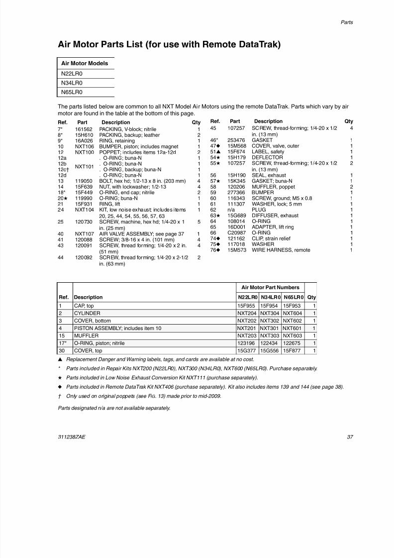
Air Motor Parts List (for use with Remote DataTrak)
The parts listed below are common to all NXT Model Air Motors using the remote DataTrak. Parts which vary by airmotor are found in the table at the bottom of this page.
Replacement Danger and Warning labels, tags, and cards are available at no cost.
* Parts included in Repair Kits NXT200 (N22LR0), NXT300 (N34LR0), NXT600 (N65LR0). Purchase separately.
Parts included in Low Noise Exhaust Conversion Kit NXT111 (purchase separately).
Parts included in Remote DataTrak Kit NXT406 (purchase separately). Kit also includes items 139 and 144 (see page 38 ).
† Only used on original poppets (see F IG . 13) made prior to mid-2009.
Parts designated n/a are not available separately.
Air Motor Models
N22LR0
N34LR0
N65LR0
Ref. Part Description Qty
7* 161562 PACKING, V-block; nitrile 18* 15H610 PACKING, backup; leather 29* 16A026 RING, retaining 110 NXT106 BUMPER, piston; includes magnet 112 NXT100 POPPET; includes items 12a-12d 212a
NXT101
. O-RING; buna-N 112b . O-RING; buna-N 112c† . O-RING, backup; buna-N 1
12d . O-RING; buna-N 113 119050 BOLT, hex hd; 1/2-13 x 8 in. (203 mm) 414 15F639 NUT, with lockwasher; 1/2-13 418* 15F449 O-RING, end cap; nitrile 220 119990 O-RING; buna-N 121 15F931 RING, lift 124 NXT104 KIT, low noise exhaust; includes items
20, 25, 44, 54, 55, 56, 57, 63
1
25 120730 SCREW, machine, hex hd; 1/4-20 x 1
in. (25 mm)
5
40 NXT107 AIR VALVE ASSEMBLY; see page 37 141 120088 SCREW; 3/8-16 x 4 in. (101 mm) 443 120091 SCREW, thread forming; 1/4-20 x 2 in.
(51 mm)
4
44 120092 SCREW, thread forming; 1/4-20 x 2-1/2
in. (63 mm)
2
45 107257 SCREW, thread-forming; 1/4-20 x 1/2
in. (13 mm)
4
46* 253476 GASKET 147 15M568 COVER, valve, outer 151 15F674 LABEL, safety 154 15H179 DEFLECTOR 155 107257 SCREW, thread-forming; 1/4-20 x 1/2
in. (13 mm)
2
56 15H190 SEAL, exhaust 157 15K345 GASKET; buna-N 158 120206 MUFFLER, poppet 259 277366 BUMPER 160 116343 SCREW, ground; M5 x 0.8 161 111307 WASHER, lock; 5 mm 162 n/a PLUG 163 15G689 DIFFUSER, exhaust 164 108014 O-RING 165 16D001 ADAPTER, lift ring 166 C20987 O-RING 174 121162 CLIP, strain relief 175 117018 WASHER 176 15M573 WIRE HARNESS, remote 1
Ref. Part Description Qty
Ref. Description
Air Motor Part Numbers
QtyN22LR0 N34LR0 N65LR0
1 CAP, top 15F955 15F954 15F953 1
2 CYLINDER NXT204 NXT304 NXT604 1
3 COVER, bottom NXT202 NXT302 NXT602 1
4 PISTON ASSEMBLY; includes item 10 NXT201 NXT301 NXT601 1
15 MUFFLER NXT203 NXT303 NXT603 1
17* O-RING, piston; nitrile 123196 122434 122675 1
30 COVER, top 15G377 15G556 15F877 1
8/12/2019 311238 Xtreme - Air Motor
http://slidepdf.com/reader/full/311238-xtreme-air-motor 38/46
Parts
38 311238ZAE
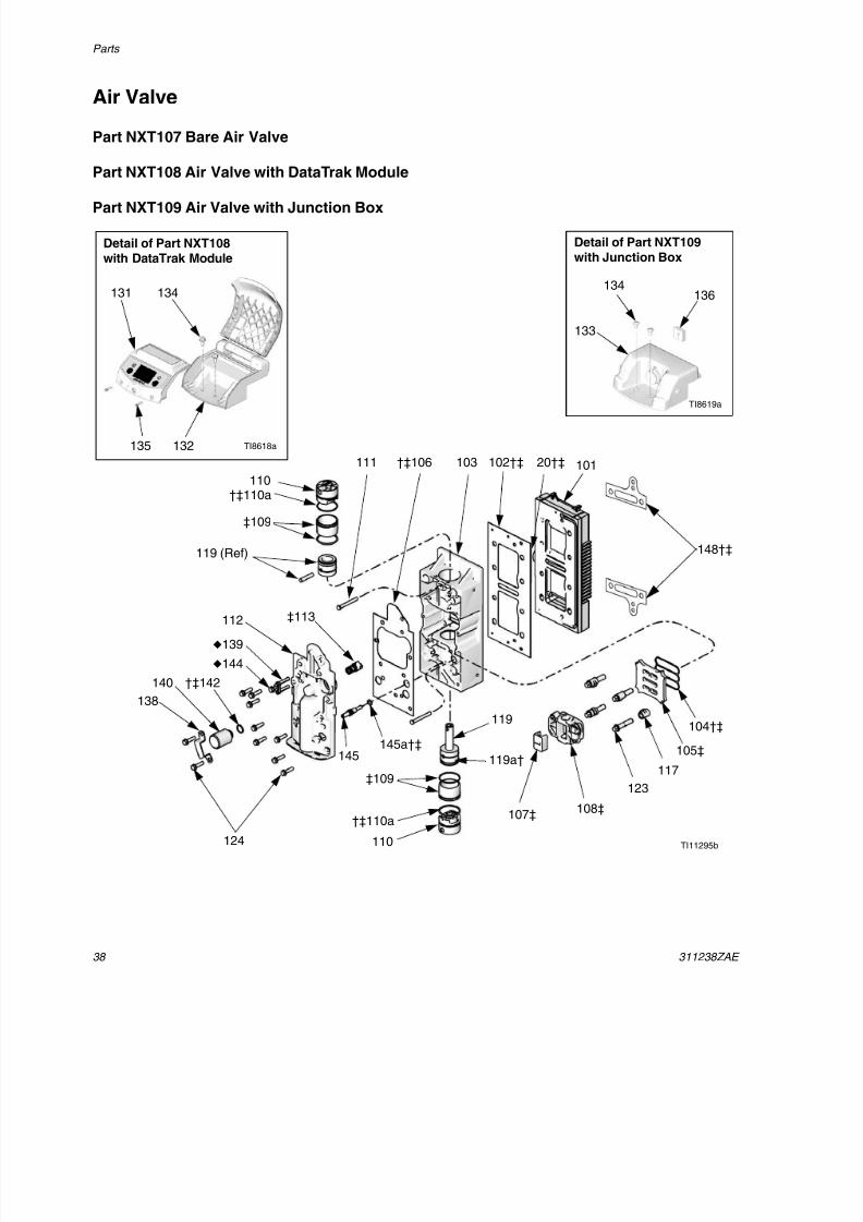
Air Valve
Part NXT107 Bare Air Valve
Part NXT108 Air Valve with DataTrak Module
Part NXT109 Air Valve with Junction Box
TI11295b
102†‡ 101
104†‡
105‡
117123
108‡107‡
‡113
124
138
140 †‡142
112
†‡106111 103
132
134
145
139
144
131
135
134
133
Detail of Part NXT108with DataTrak Module
Detail of Part NXT109with Junction Box
TI8619a
TI8618a
136
‡109
‡109
110
119
110
119 (Ref)
20†‡
119a†
†‡110a
148†‡
145a†‡
†‡110a
8/12/2019 311238 Xtreme - Air Motor
http://slidepdf.com/reader/full/311238-xtreme-air-motor 39/46
Parts
311238ZAE 39
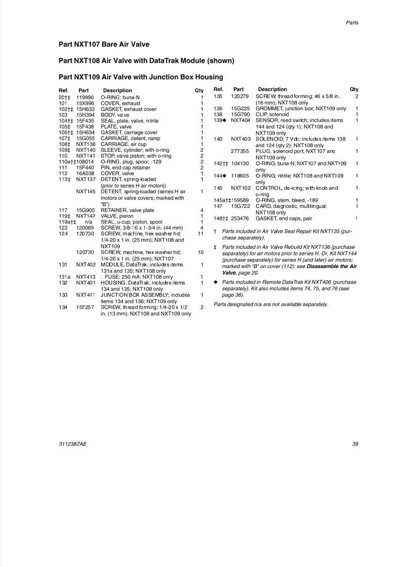
Part NXT107 Bare Air Valve
Part NXT108 Air Valve with DataTrak Module (shown)
Part NXT109 Air Valve with Junction Box Housing
† Parts included in Air Valve Seal Repair Kit NXT135 (pur-
chase separately).
‡ Parts included in Air Valve Rebuild Kit NXT136 (purchase
separately) for air motors prior to series H. Or, Kit NXT144
(purchase separately) for series H (and later) air motors;
marked with “B” on cover (112); see Disassemble the AirValve , page 20 .
Parts included in Remote DataTrak Kit NXT406 (purchase
separately). Kit also includes items 74, 75, and 76 (see
page 36 ).
Parts designated n/a are not available separately.
Ref. Part Description Qty20†‡ 119990 O-RING; buna-N 1101 15X996 COVER, exhaust 1102†‡ 15H633 GASKET, exhaust cover 1103 15H394 BODY, valve 1104†‡ 15F435 SEAL, plate, valve; nitrile 1105‡ 15F438 PLATE, valve 1106†‡ 15H634 GASKET, carriage cover 1107‡ 15G055 CARRIAGE, detent, ramp 1108‡ NXT138 CARRIAGE, air cup 1109‡ NXT140 SLEEVE, cylinder; with o-ring 2110 NXT141 STOP, valve piston; with o-ring 2110a†‡108014 O-RING, plug, spool; -129 2111 15F440 PIN, end cap retainer 2112 16A038 COVER, valve 1
113‡ NXT137 DETENT, spring-loaded(prior to series H air motors)
1
NXT145 DETENT, spring-loaded (series H air
motors or valve covers; marked with
“B”)
1
117 15G905 RETAINER, valve plate 4119‡ NXT142 VALVE, piston 1119a†‡ n/a SEAL, u-cup, piston, spool 1123 120089 SCREW, 3/8-16 x 1-3/4 in. (44 mm) 4124 120730 SCREW, machine, hex washer hd;
1/4-20 x 1 in. (25 mm); NXT108 and
NXT109
11
120730 SCREW, machine, hex washer hd;
1/4-20 x 1 in. (25 mm); NXT107
10
131 NXT402 MODULE, DataTrak; includes items
131a and 135; NXT108 only
1
131a NXT413 . FUSE; 250 mA; NXT108 only 1132 NXT401 HOUSING, DataTrak; includes items
134 and 135; NXT108 only
1
133 NXT411 JUNCTION BOX ASSEMBLY; includes
items 134 and 136; NXT109 only
1
134 107257 SCREW, thread forming; 1/4-20 x 1/2
in. (13 mm); NXT108 and NXT109 only
2
135 120279 SCREW, thread forming; #6 x 5/8 in.
(16 mm); NXT108 only
2
136 15G225 GROMMET, junction box; NXT109 only 1138 15G790 CLIP, solenoid 1139 NXT404 SENSOR, reed switch; includes items
144 and 124 (qty 1); NXT108 and
NXT109 only
1
140 NXT403 SOLENOID; 7 Vdc; includes items 138
and 124 (qty 2); NXT108 only
1
277355 PLUG, solenoid port; NXT107 and
NXT109 only
1
142†‡ 104130 O-RING; buna-N; NXT107 and NXT109
only
1
144
118605 O-RING; nitrile; NXT108 and NXT109only 1
145 NXT102 CONTROL, de-icing; with knob and
o-ring
1
145a†‡159589 O-RING, stem, bleed, -189 1147 15G722 CARD, diagnostic, multilingual;
NXT108 only
1
148†‡ 253476 GASKET, end caps, pair 1
Ref. Part Description Qty
8/12/2019 311238 Xtreme - Air Motor
http://slidepdf.com/reader/full/311238-xtreme-air-motor 40/46
Dimensions
40 311238ZAE
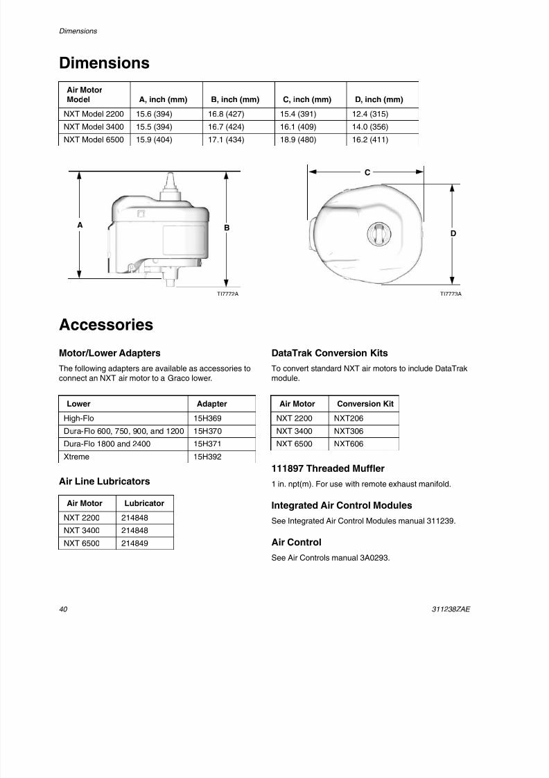
Dimensions
Accessories
Motor/Lower Adapters
The following adapters are available as accessories toconnect an NXT air motor to a Graco lower.
Air Line Lubricators
DataTrak Conversion Kits
To convert standard NXT air motors to include DataTrakmodule.
111897 Threaded Muffler
1 in. npt(m). For use with remote exhaust manifold.
Integrated Air Control Modules
See Integrated Air Control Modules manual 311239.
Air Control
See Air Controls manual 3A0293.
Air MotorModel A, inch (mm) B, inch (mm) C, inch (mm) D, inch (mm)
NXT Model 2200 15.6 (394) 16.8 (427) 15.4 (391) 12.4 (315)
NXT Model 3400 15.5 (394) 16.7 (424) 16.1 (409) 14.0 (356)
NXT Model 6500 15.9 (404) 17.1 (434) 18.9 (480) 16.2 (411)
TI7773ATI7772A
A B
C
D
Lower Adapter
High-Flo 15H369
Dura-Flo 600, 750, 900, and 1200 15H370
Dura-Flo 1800 and 2400 15H371
Xtreme 15H392
Air Motor Lubricator
NXT 2200 214848
NXT 3400 214848
NXT 6500 214849
Air Motor Conversion Kit
NXT 2200 NXT206
NXT 3400 NXT306
NXT 6500 NXT606
8/12/2019 311238 Xtreme - Air Motor
http://slidepdf.com/reader/full/311238-xtreme-air-motor 41/46
Mounting Hole Diagrams
311238ZAE 4
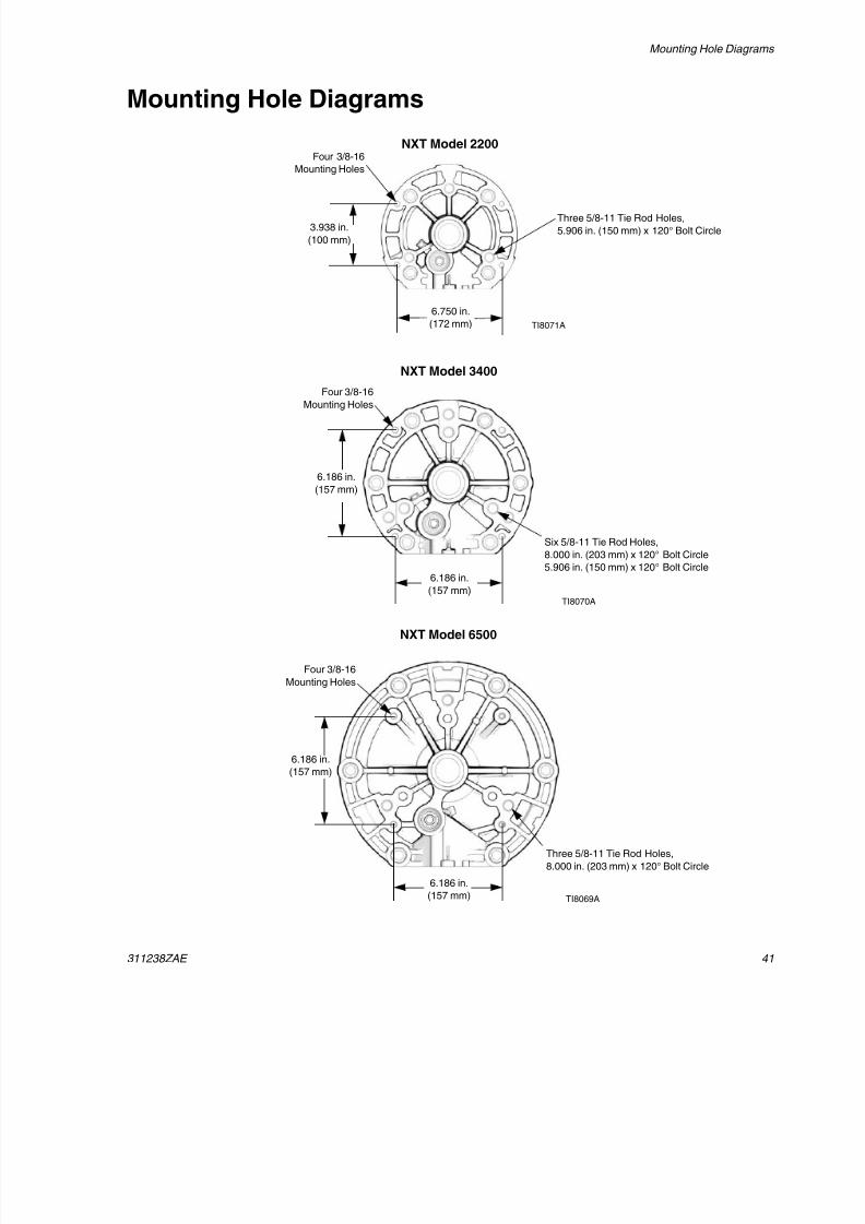
Mounting Hole Diagrams
NXT Model 2200
NXT Model 3400
NXT Model 6500
TI8069A
TI8071A
TI8070A
6.186 in.
(157 mm)
Three 5/8-11 Tie Rod Holes,
8.000 in. (203 mm) x 120° Bolt Circle
Six 5/8-11 Tie Rod Holes,
8.000 in. (203 mm) x 120° Bolt Circle
5.906 in. (150 mm) x 120° Bolt Circle
Three 5/8-11 Tie Rod Holes,
5.906 in. (150 mm) x 120° Bolt Circle
Four 3/8-16
Mounting Holes
6.186 in.
(157 mm)
6.186 in.
(157 mm)
6.186 in.(157 mm)
3.938 in.
(100 mm)
Four 3/8-16
Mounting Holes
Four 3/8-16
Mounting Holes
6.750 in.
(172 mm)
8/12/2019 311238 Xtreme - Air Motor
http://slidepdf.com/reader/full/311238-xtreme-air-motor 42/46
Technical Data
42 311238ZAE
Technical Data
Santoprene ® is a registered trademark of the Monsanto Company.
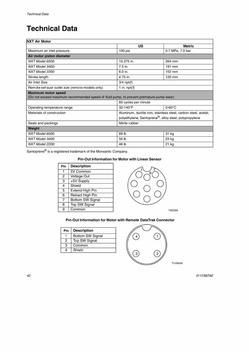
NXT Air Motor
US Metric
Maximum air inlet pressure 100 psi 0.7 MPa, 7.0 bar
Air motor piston diameter
NXT Model 6500: 10.375 in. 264 mm
NXT Model 3400: 7.5 in. 191 mm
NXT Model 2200: 6.0 in. 152 mm
Stroke length 4.75 in. 120 mm
Air Inlet Size 3/4 npt(f)
Remote exhaust outlet size (remote models only) 1 in. npt(f)
Maximum motor speed
(Do not exceed maximum recommended speed of fluid pump, to prevent premature pump wear)
60 cycles per minute
Operating temperature range 32-140°F 0-60°C
Materials of construction Aluminum, ductile iron, stainless steel, carbon steel, acetal,
polyethylene, Santoprene ® , alloy steel, polypropylene
Seals and packings Nitrile rubber
Weight
NXT Model 6500: 69 lb 31 kg
NXT Model 3400: 50 lb 23 kg
NXT Model 2200: 46 lb 21 kg
TI9239A
19
7
Pin-Out Information for Motor with Linear Sensor
Pin Description1 5V Common
2 Voltage Out
3 +5V Supply
4 Shield
5 Extend High Pin
6 Retract High Pin
7 Bottom SW Signal
8 Top SW Signal
9 Common
Pin-Out Information for Motor with Remote DataTrak Connector
Pin Description
1 Bottom SW Signal
2 Top SW Signal
3 Common
4 Shield
TI10950A
1
23
4
8/12/2019 311238 Xtreme - Air Motor
http://slidepdf.com/reader/full/311238-xtreme-air-motor 43/46
Technical Data
311238ZAE 43
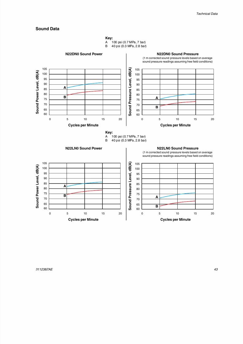
Sound Data
N22DN0 Sound Power N22DN0 Sound Pressure(1 m corrected sound pressure levels based on average
sound pressure readings assuming free field conditions)
S o u
n d P o w e r L e v e l , d B ( A )
S o u n
d P r e s s u r e L e v e l , d B ( A )
Cycles per Minute
105
100
95
90
85
80
75
70
65
60
105
100
95
90
85
80
75
70
65
60
0 5 10 15 20
Cycles per Minute
0 5 10 15 20
Key:A 100 psi (0.7 MPa, 7 bar)
B 40 psi (0.3 MPa, 2.8 bar)
A
B A
B
N22LN0 Sound Power N22LN0 Sound Pressure(1 m corrected sound pressure levels based on average
sound pressure readings assuming free field conditions)
S o u n d P o w e r L e v e l , d B ( A )
S o u n d P r e s s u r e L e v e l , d B ( A )
Cycles per Minute
105
100
95
90
85
80
75
70
65
60
105
100
95
90
85
80
75
70
65
60
0 5 10 15 20
Cycles per Minute
0 5 10 15 20
Key:A 100 psi (0.7 MPa, 7 bar)
B 40 psi (0.3 MPa, 2.8 bar)
A
B A
B
8/12/2019 311238 Xtreme - Air Motor
http://slidepdf.com/reader/full/311238-xtreme-air-motor 44/46
Technical Data
44 311238ZAE
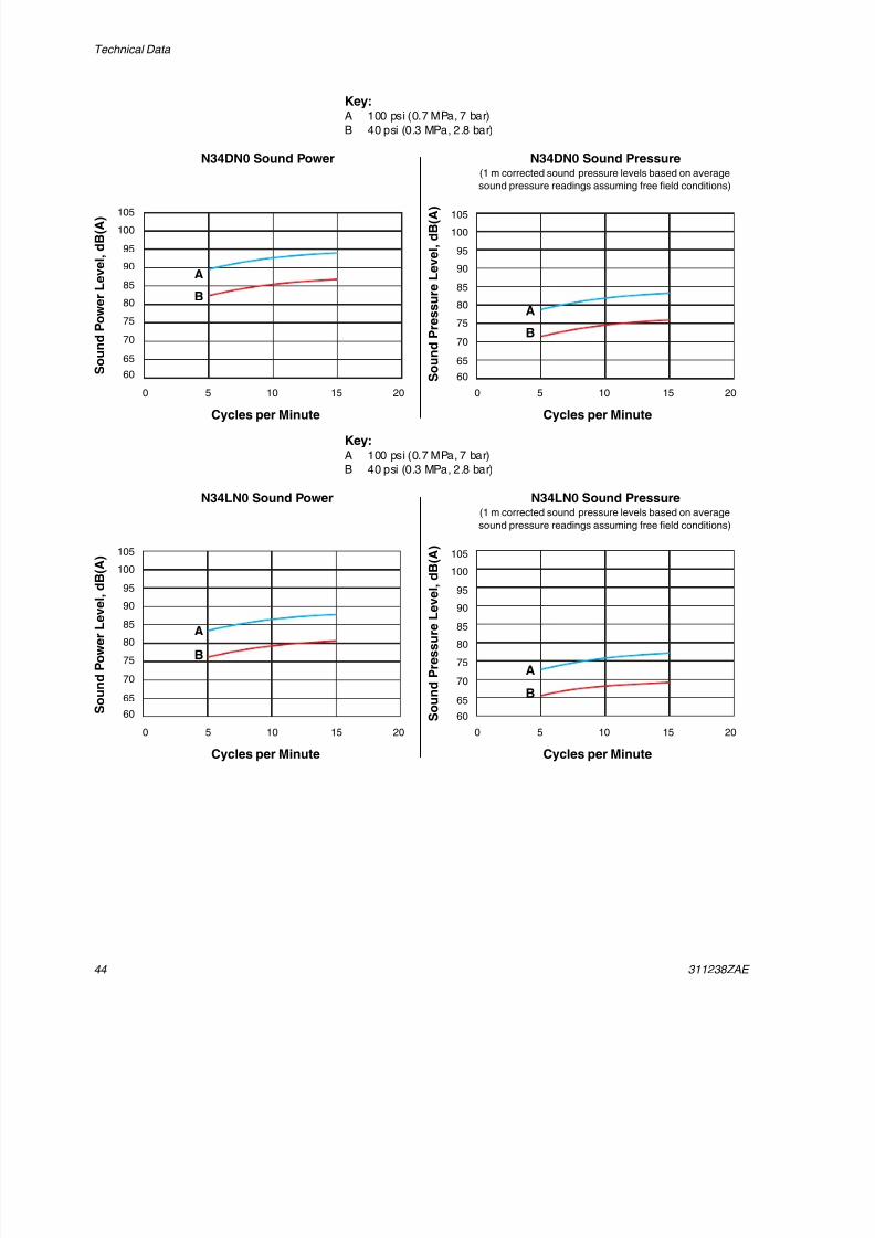
N34DN0 Sound Power N34DN0 Sound Pressure(1 m corrected sound pressure levels based on average
sound pressure readings assuming free field conditions)
S o u n d P o w e r L e v e l , d B ( A )
S o u n d P r e s s u r e L e v e l , d B ( A )
Cycles per Minute
105
100
95
90
85
80
75
70
65
60
105
100
95
90
85
80
75
70
65
60
0 5 10 15 20
Cycles per Minute
0 5 10 15 20
Key:A 100 psi (0.7 MPa, 7 bar)
B 40 psi (0.3 MPa, 2.8 bar)
A
BA
B
N34LN0 Sound Power N34LN0 Sound Pressure(1 m corrected sound pressure levels based on average
sound pressure readings assuming free field conditions)
S o u n d P o w e r L e v e l , d B ( A )
S o u n d P r e s s u r e L e v e l ,
d B ( A )
Cycles per Minute
105
100
95
90
85
80
75
70
65
60
105
100
95
90
85
80
75
70
65
60
0 5 10 15 20
Cycles per Minute
0 5 10 15 20
Key:A 100 psi (0.7 MPa, 7 bar)
B 40 psi (0.3 MPa, 2.8 bar)
A
BA
B
8/12/2019 311238 Xtreme - Air Motor
http://slidepdf.com/reader/full/311238-xtreme-air-motor 45/46
Technical Data
311238ZAE 45
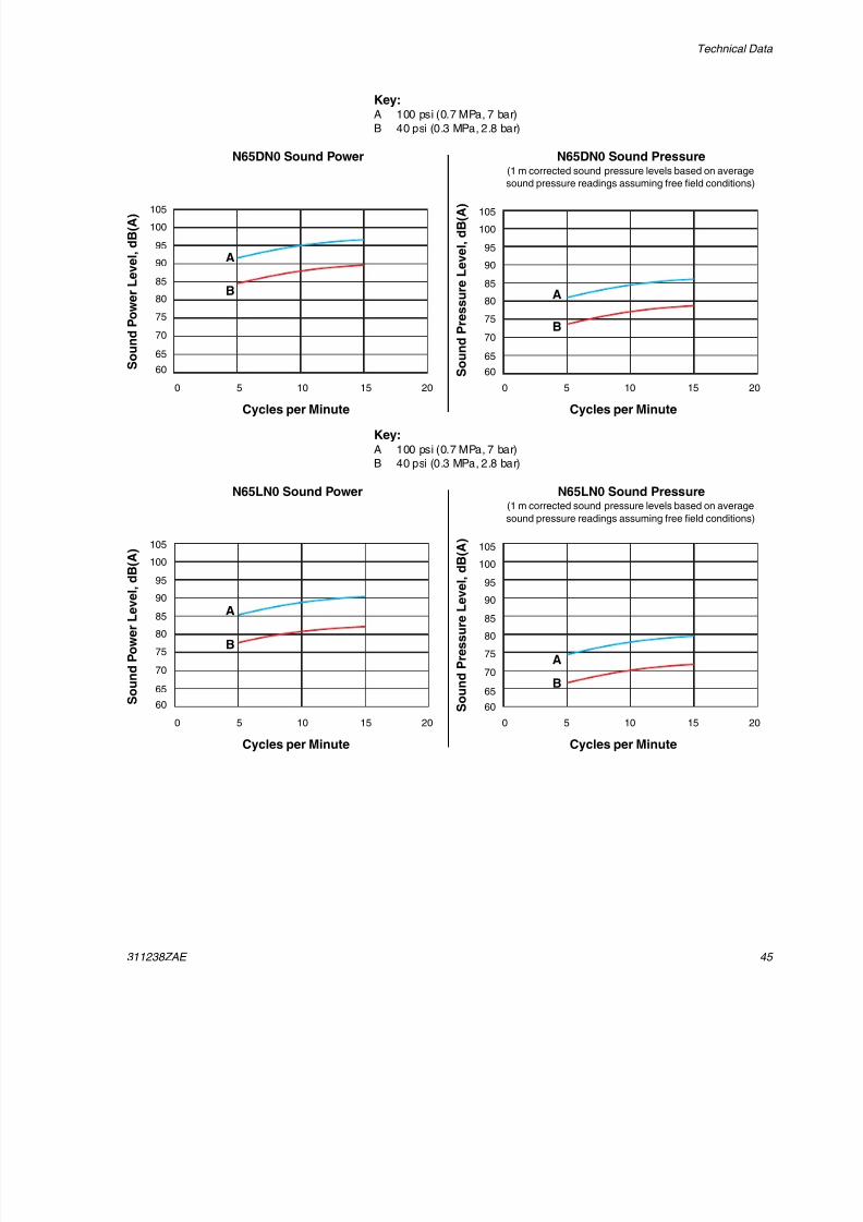
N65DN0 Sound Power N65DN0 Sound Pressure(1 m corrected sound pressure levels based on average
sound pressure readings assuming free field conditions)
S o u n d P o w e r L e v e l , d B ( A )
S o u n d P r e s s u r e L e v e l , d B ( A )
Cycles per Minute
105
100
95
90
85
80
75
70
65
60
105
100
95
90
85
80
75
70
65
60
0 5 10 15 20
Cycles per Minute
0 5 10 15 20
Key:A 100 psi (0.7 MPa, 7 bar)
B 40 psi (0.3 MPa, 2.8 bar)
A
B A
B
N65LN0 Sound Power N65LN0 Sound Pressure(1 m corrected sound pressure levels based on average
sound pressure readings assuming free field conditions)
S o u n d P o w e r L e v e l , d B ( A )
S o u n d P r e s s u r e L e v e l ,
d B ( A )
Cycles per Minute
105
100
95
90
85
80
75
70
65
60
105
100
95
90
85
80
75
70
65
60
0 5 10 15 20
Cycles per Minute
0 5 10 15 20
Key:A 100 psi (0.7 MPa, 7 bar)
B 40 psi (0.3 MPa, 2.8 bar)
A
B
A
B
8/12/2019 311238 Xtreme - Air Motor
http://slidepdf.com/reader/full/311238-xtreme-air-motor 46/46
All written and visual data contained in this document reflects the latest product information available at the time of publication.Graco reserves the right to make changes at any time without notice.
Graco Standard Warranty
Graco warrants all equipment referenced in this document which is manufactured by Graco and bearing its name to be free from defects in
material and workmanship on the date of sale to the original purchaser for use. With the exception of any special, extended, or limited warranty
published by Graco, Graco will, for a period of twelve months from the date of sale, repair or replace any part of the equipment determined by
Graco to be defective. This warranty applies only when the equipment is installed, operated and maintained in accordance with Graco’s written
recommendations.This warranty does not cover, and Graco shall not be liable for general wear and tear, or any malfunction, damage or wear caused by faulty
installation, misapplication, abrasion, corrosion, inadequate or improper maintenance, negligence, accident, tampering, or substitution of
non-Graco component parts. Nor shall Graco be liable for malfunction, damage or wear caused by the incompatibility of Graco equipment with
structures, accessories, equipment or materials not supplied by Graco, or the improper design, manufacture, installation, operation or
maintenance of structures, accessories, equipment or materials not supplied by Graco.
This warranty is conditioned upon the prepaid return of the equipment claimed to be defective to an authorized Graco distributor for verification of
the claimed defect. If the claimed defect is verified, Graco will repair or replace free of charge any defective parts. The equipment will be returned
to the original purchaser transportation prepaid. If inspection of the equipment does not disclose any defect in material or workmanship, repairs will
be made at a reasonable charge, which charges may include the costs of parts, labor, and transportation.
THIS WARRANTY IS EXCLUSIVE, AND IS IN LIEU OF ANY OTHER WARRANTIES, EXPRESS OR IMPLIED, INCLUDING BUT NOT LIMITED
TO WARRANTY OF MERCHANTABILITY OR WARRANTY OF FITNESS FOR A PARTICULAR PURPOSE.
Graco’s sole obligation and buyer’s sole remedy for any breach of warranty shall be as set forth above. The buyer agrees that no other remedy
(including, but not limited to, incidental or consequential damages for lost profits, lost sales, injury to person or property, or any other incidental or
consequential loss) shall be available. Any action for breach of warranty must be brought within two (2) years of the date of sale.
GRACO MAKES NO WARRANTY, AND DISCLAIMS ALL IMPLIED WARRANTIES OF MERCHANTABILITY AND FITNESS FOR A
PARTICULAR PURPOSE, IN CONNECTION WITH ACCESSORIES, EQUIPMENT, MATERIALS OR COMPONENTS SOLD BUT NOT
MANUFACTURED BY GRACO. These items sold, but not manufactured by Graco (such as electric motors, switches, hose, etc.), are subject to
the warranty, if any, of their manufacturer. Graco will provide purchaser with reasonable assistance in making any claim for breach of these
warranties.
In no event will Graco be liable for indirect, incidental, special or consequential damages resulting from Graco supplying equipment hereunder, or
the furnishing, performance, or use of any products or other goods sold hereto, whether due to a breach of contract, breach of warranty, the
negligence of Graco, or otherwise.
FOR GRACO CANADA CUSTOMERS
The Parties acknowledge that they have required that the present document, as well as all documents, notices and legal proceedings entered into,
given or instituted pursuant hereto or relating directly or indirectly hereto, be drawn up in English. Les parties reconnaissent avoir convenu que la
rédaction du présente document sera en Anglais, ainsi que tous documents, avis et procédures judiciaires exécutés, donnés ou intentés, à la suite
de ou en rapport, directement ou indirectement, avec les procédures concernées.
Graco Information
For the latest information about Graco products, visit www.graco.com.
TO PLACE AN ORDER, contact your Graco distributor or call to identify the nearest distributor.Phone: 612-623-6921 or Toll Free: 1-800-328-0211 Fax: 612-378-3505