Embed Size (px)
Citation preview

DescriptionThe 31000/32000 Proximity Probe Housing Assemblies arerecommended when mounting proximity probes through themachine case and are typically used for radially mountedtransducers, whether vibration or Keyphasor measurements.
1. When using these housings to measure radial vibration,ensure that the machine casing is affixed to the bearing inorder to get an accurate relative vibration signal.
2. When measuring shaft axial position with dual proximityprobes, use housing 21022 instead. Consult specifications andordering information (p/n 141601-01).
Use of a Proximity probe housing allows external access to theproximity probe and its extension cable, permitting gapadjustment or probe replacement without disassembly of themachine. The 31000/32000 Proximity Probe Housing Assemblyis made of polyphenylene sulfide (PPS), an advanced, high-strength, thermoplastic with excellent corrosion resistance.Other elements of the housing assembly are made ofcorrosion-resistant stainless steel. The housing can be orderedwith installed 3300 XL Proximity Probes and a variety ofconduit fittings.
The 31000/32000 Proximity Probe Housing Assembly is fullycompliant with the American Petroleum Institute's (API) 670Standard for externally mounted proximity probe housings.
When installed in conjunction with an approved transducersystem and appropriate I.S. barriers, the 31000/32000Proximity Probe Housing Assembly can be used in intrinsicallysafe hazardous area applications.
The 31000/32000 Housing is intended to providemechanical and environmental protection only, and is not anexplosion-proof housing. When an explosion proof proximityprobe housing assembly is required, use housing CA21000 orCA24701. Consult the datasheet (document 141600).
Document: 141610Rev. J
31000 and 32000 Proximity Probe HousingAssembliesDatasheetBently Nevada Machinery Condition Monitoring
Related Documents
For probe information, refer to the followingmanuals:
n 3300 XL 8mm & 3300 5mm ProximityTransducer System User Guide (document141078)
n 3300 XL NSv Proximity Transducer SystemUser Guide (document 147357)
n 3300 XL 11mm Proximity TransducerSystem Installation User Guide (document146255)
n Radiation Resistant Probe and ProximitorSystem (Document TW8029407)
31000 and 32000 Proximity Probe Housing AssembliesDatasheet
2/15 141610 Rev. J
SpecificationsEnvironmental
Temperature Range
-51 °C to +105 °C (-60 °F to + 221 °F)
Hot Water and Steam Exposure Effects
(Specification not guaranteed)Brief periods (up to one week) of contact withhot water (95°C [203°F]) and/or condensingsteam should not significantly affect thestrength of the plastic housing. Contact withthese beyond this length of time may eventuallycause the strength of the plastic housing topermanently decrease during the first 6 to 8weeks of exposure, and then level atapproximately half of its initial value. Tests ofactual housing performance after contact withhot water and condensing steam have not beenconducted.
Probe Pressure
The 31000/32000 Proximity Probe HousingAssembly is designed to seal differentialpressure between the probe tip and the housingmain body when used with a 3300 XL 8 mmprobe. The sealing material internal to theprobe case consists of a Viton O-ring; the O-ring between the sleeve and the housing is aNeoprene O-ring. The plastic housing iscertified to seal against hose-directed wateraccording to NEMA 4X and IP66 standards but isnot designed to resist internal or externalpressure. Probes are not pressure tested prior toshipment. Contact our custom designdepartment if you require a test of the pressureseal for your application.
It is the responsibility of the customer or user toensure that all liquids and gases are containedand safely controlled should leakage occur froma Proximity Probe Housing Assembly. Solutionswith high or low pH values may erode the tip
assembly of the probe, causing media leakageinto surrounding areas. Bently Nevada, LLC, willnot be held responsible for any damagesresulting from leaking Proximity Probe HousingAssemblies. In addition, Proximity ProbeHousing Assemblies and 3300 XL 8 mmproximity probes will not be replaced under theservice plan due to probe leakage.
Mechanical
Protection Ratings Type 4X rating certified byCanadian StandardsAssociation (CSA). IP66 ratingverified by SC115582-1 (e)106. CENELEC standardEN50014 rating forelectrostatic dissipation of aplastic material located in ahazardous area.
Housing Material Glass-reinforcedPolyphenylene Sulfide (PPS)thermoplastic containingconductive fibers
Sleeve Material andRetaining Chain
AISI 304 stainless steel
Outer Sleeve andExterior Screws
AISI 303 stainless steel
O-Ring Material Neoprene
RecommendedTorque(retainingnut)
29.4 N·m (260 in·lb)
Housing Strength(typical)
Outer sleeve was mountedon a test stand with its axisparallel to horizontal and thehousing mounted on theouter sleeve through an endhole. The housing supported912 N (205 lb) placedapproximately 38 mm (1.5inches) from theunsupported end with thecover fastened in place andgrounding liner installed
Housing ImpactStrength
Certified by BASEEFA towithstand two separate 4Joule (3.0 ft·lb) impacts at -39°C (-38°F) and at 115 °C
31000 and 32000 Proximity Probe Housing AssembliesDatasheet
3/15 141610 Rev. J
(239°F). Samples of thehousing and cover wereverified by CSA to withstand a7 Joule (5.2 ft·lb) impact atambient room temperature.
Weight 1.2 kg (2.6 lb) typical
31000 and 32000 Proximity Probe Housing AssembliesDatasheet
4/15 141610 Rev. J

Compliance and Certifications
FCCThis device complies with part 15 of theFCC Rules. Operation is subject to thefollowing two conditions:
l This device may not cause harmfulinterference.
l This device must accept anyinterference received, includinginterference that may causeundesired operation.
RoHSRoHS Directive 2011/65/EU
Hazardous Area ApprovalsFor the detailed listing of country and product specificapprovals, refer to the Approvals Quick ReferenceGuide, Document 108M1756, at Bently.com.
21000 and 24701CA housings are certified by CSA for explosion -proof applications in the following areas:
NorthAmerica
Class 1 Divisions 1 and 2 Groups C andD
Class 2 Divisions 1 and 2 Groups E, Fand G
Class III
Enclosure Type 4
T5@ Ta = -50 °C to +40 °CT4@ Ta = -50 °C to +80 °C
31000 and 32000 Proximity Probe Housing AssembliesDatasheet
5/15 141610 Rev. J

Ordering InformationFor the detailed listing of country and product specificapprovals, refer to the Approvals Quick ReferenceGuide, Document 108M1756, at Bently.com.
Table 1: Maximum "C" Option plus "D"Option for different "B" Options (probecable length)
Probe CableLength
Maximum C plus D
0.5 meter 394 mm (15.5 in)
1.0 meter 760 mm (30.0 in)
Table 2: Maximum "C" Option plus "D"Option for different "B" Options (probecable length) where P/N and S/N Labelon Probe Cable is visible outside ofprobe sleeve
Probe CableLength
Maximum C plus D with VisibleP/N and S/N Label
0.5 meter 64 mm (2.5 in)
1.0 meter 483 mm (19.0 in)
Conduit fittings are necessary when hardlineconduit or metal tubing is brought into thehousing. Flexible conduit should be orderedwith integral 3/4-14 NPT fittings and do notrequire additional conduit fittings with thehousing. If using flexible conduit, order the "E"= 00 option.
English Proximity Probe HousingAssemblies
31000 - AA-BB-CC-DDD-EE-FF
A: Probe with Connector
00 Probe not required
16 3300 XL 8 mmprobe
26 3300 XL NSv probe
27 3300 XL NSv probe, multiple approvals
28 3300 XL 8 mmprobe, multiple approvals
29 3300 XL 8 mmprobe, with connectorprotector
30 3300 XL 8 mmprobe, with connectorprotector, multiple approvals
31 3300 XL NSv probe with connector protector
32 3300 XL NSv probe with connector protector,multiple approvals
33 3300 XL 11 mmprobe
34 3300 XL 11 mmprobe, multiple approvals
35 3300 XL 11 mmprobe with connectorprotector
36 3300 XL 11 mmprobe with connectorprotector, multiple approvals
B: Probe Cable Length00 Probe cable not required
05 0.5 m (20 in)
10 1.0 m (39 in)
C: Standoff Adapter Length (Option C Dimension)Must be ordered if Standoff Adapter Lengthoption is not 00.
15 Minimum length 1.5 in (38 mm)
75 Maximum length 7.5 in (191 mm)Recommendation
Order in increments of 0.5 in (13 mm)
Examples
1.5 in (38 mm) = 15No standoff adapter = 00
C: Probe Penetration Option (Option D
31000 and 32000 Proximity Probe Housing AssembliesDatasheet
6/15 141610 Rev. J
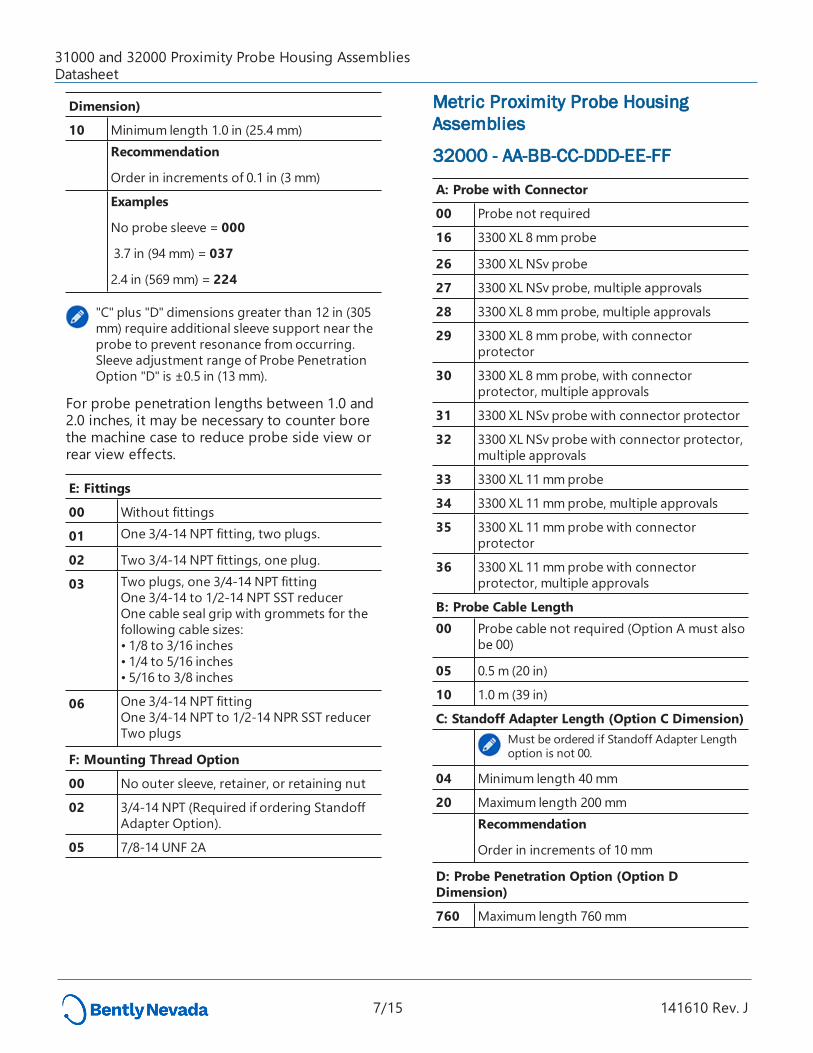
Dimension)
10 Minimum length 1.0 in (25.4 mm)Recommendation
Order in increments of 0.1 in (3 mm)
Examples
No probe sleeve = 000
3.7 in (94 mm) = 037
2.4 in (569 mm) = 224
"C" plus "D" dimensions greater than 12 in (305mm) require additional sleeve support near theprobe to prevent resonance from occurring.Sleeve adjustment range of Probe PenetrationOption "D" is ±0.5 in (13 mm).
For probe penetration lengths between 1.0 and2.0 inches, it may be necessary to counter borethe machine case to reduce probe side view orrear view effects.
E: Fittings
00 Without fittings
01 One 3/4-14 NPT fitting, two plugs.
02 Two 3/4-14 NPT fittings, one plug.
03 Two plugs, one 3/4-14 NPT fittingOne 3/4-14 to 1/2-14 NPT SST reducerOne cable seal grip with grommets for thefollowing cable sizes:• 1/8 to 3/16 inches• 1/4 to 5/16 inches• 5/16 to 3/8 inches
06 One 3/4-14 NPT fittingOne 3/4-14 NPT to 1/2-14 NPR SST reducerTwo plugs
F: Mounting Thread Option
00 No outer sleeve, retainer, or retaining nut
02 3/4-14 NPT (Required if ordering StandoffAdapter Option).
05 7/8-14 UNF 2A
Metric Proximity Probe HousingAssemblies
32000 - AA-BB-CC-DDD-EE-FF
A: Probe with Connector
00 Probe not required
16 3300 XL 8 mmprobe
26 3300 XL NSv probe
27 3300 XL NSv probe, multiple approvals
28 3300 XL 8 mmprobe, multiple approvals
29 3300 XL 8 mmprobe, with connectorprotector
30 3300 XL 8 mmprobe, with connectorprotector, multiple approvals
31 3300 XL NSv probe with connector protector
32 3300 XL NSv probe with connector protector,multiple approvals
33 3300 XL 11 mmprobe
34 3300 XL 11 mmprobe, multiple approvals
35 3300 XL 11 mmprobe with connectorprotector
36 3300 XL 11 mmprobe with connectorprotector, multiple approvals
B: Probe Cable Length00 Probe cable not required (Option A must also
be 00)
05 0.5 m (20 in)
10 1.0 m (39 in)
C: Standoff Adapter Length (Option C Dimension)Must be ordered if Standoff Adapter Lengthoption is not 00.
04 Minimum length 40 mm
20 Maximum length 200 mmRecommendation
Order in increments of 10 mm
D: Probe Penetration Option (Option DDimension)
760 Maximum length 760 mm
31000 and 32000 Proximity Probe Housing AssembliesDatasheet
7/15 141610 Rev. J
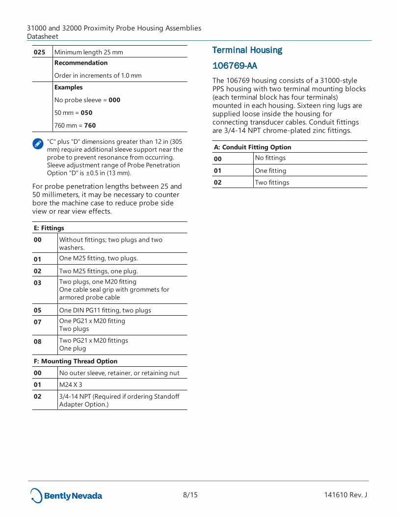
025 Minimum length 25 mmRecommendation
Order in increments of 1.0 mm
Examples
No probe sleeve = 000
50 mm= 050
760 mm= 760
"C" plus "D" dimensions greater than 12 in (305mm) require additional sleeve support near theprobe to prevent resonance from occurring.Sleeve adjustment range of Probe PenetrationOption "D" is ±0.5 in (13 mm).
For probe penetration lengths between 25 and50 millimeters, it may be necessary to counterbore the machine case to reduce probe sideview or rear view effects.
E: Fittings
00 Without fittings; two plugs and twowashers.
01 One M25 fitting, two plugs.
02 Two M25 fittings, one plug.
03 Two plugs, one M20 fittingOne cable seal grip with grommets forarmored probe cable
05 One DIN PG11 fitting, two plugs
07 One PG21 x M20 fittingTwo plugs
08 Two PG21 x M20 fittingsOne plug
F: Mounting Thread Option
00 No outer sleeve, retainer, or retaining nut
01 M24 X 3
02 3/4-14 NPT (Required if ordering StandoffAdapter Option.)
Terminal Housing
106769-AAThe 106769 housing consists of a 31000-stylePPS housing with two terminal mounting blocks(each terminal block has four terminals)mounted in each housing. Sixteen ring lugs aresupplied loose inside the housing forconnecting transducer cables. Conduit fittingsare 3/4-14 NPT chrome-plated zinc fittings.
A: Conduit Fitting Option
00 No fittings
01 One fitting
02 Two fittings
31000 and 32000 Proximity Probe Housing AssembliesDatasheet
8/15 141610 Rev. J

Accessories
PartNumber
Description
37948-01 Probe Support / Oil SealRecommended for sleeves longerthan 305 mm (12 in)
124200 31000 and 32000 User Guide
English Probe Sleeve for 31000Proximity Probe Housings108883-AAA
A: Measured Probe Sleeve LengthRecommendation
Order in increments of 0.1 in (3 mm)
The individual probe sleeve length does notinclude the distance from the end of the sleeveto the probe tip or the gap from the probe tipto the target material. If only the part number ofthe original housing is known, and the sleevecannot be measured, use the following table todetermine the sleeve length:
AAA Optionfor 31000Prox ProbeHousing
Description
Housing AAAoption for 3300XL 8 mmprobeoption (A: 16 orA: 28)
Standoff adapter option fromoriginal housing (31000 option C)+ Probe penetration option fromoriginal housing (31000 option D)+ 0 2 5.Example
Original part number 31000-16-10-15-035-03-02
AAA option for replacementsleeve (015 + 035 + 025) = 075
Housing AAAoption for 3300XL NSv probeoption (A: 26 orA: 27)
Standoff adapter option fromoriginal housing (31000 option C)+ Probe penetration option fromoriginal housing (31000 option D)+ 0 2 6.
AAA Optionfor 31000Prox ProbeHousing
Description
Example
Original part number 31000-27-10-20-035-03-02
AAA option for replacementsleeve (020 + 035 + 026) = 0 8 1.
Housing AAAoption for 3300XL 11 mmprobeoption (A: 33 orA: 34)
Standoff Adapter Option fromoriginal housing (31000 option C)+ Probe penetration option fromoriginal housing (31000 option D)+ 0 1 7.Example
Original part number 31000-33-10-30-113-01-02
AAA option for replacementsleeve (030 + 113 + 017) = 1 6 0.
Minimum Probe Sleeve Length
3300 XL 8 mmprobes 3.5 in (89 mm) = 0 3 5
3300 XL NSv probe 3.6 in (91 mm) = 0 3 6
3300 XL 11 mmprobe 2.7 in (69 mm) = 0 2 7
Maximum Probe Sleeve Length
3300 XL 0.5 meter 8 mmprobe
18.0 in (457 mm) = 180
3300 XL NSv 0.5 meterprobe
18.1 in (460 mm) = 181
3300 XL 0.5 metre 11 mmprobe
16.0 in (406 mm) = 160
3300 XL 1.0 meter 8 mmprobe
32.5 in (826mm) = 325
3300 XL NSv 1.0 meterprobe
32.6 in (828mm) = 326
3300 XL 1.0 meter 11 mmprobe
31.7 in (805 mm) = 317
31000 and 32000 Proximity Probe Housing AssembliesDatasheet
9/15 141610 Rev. J
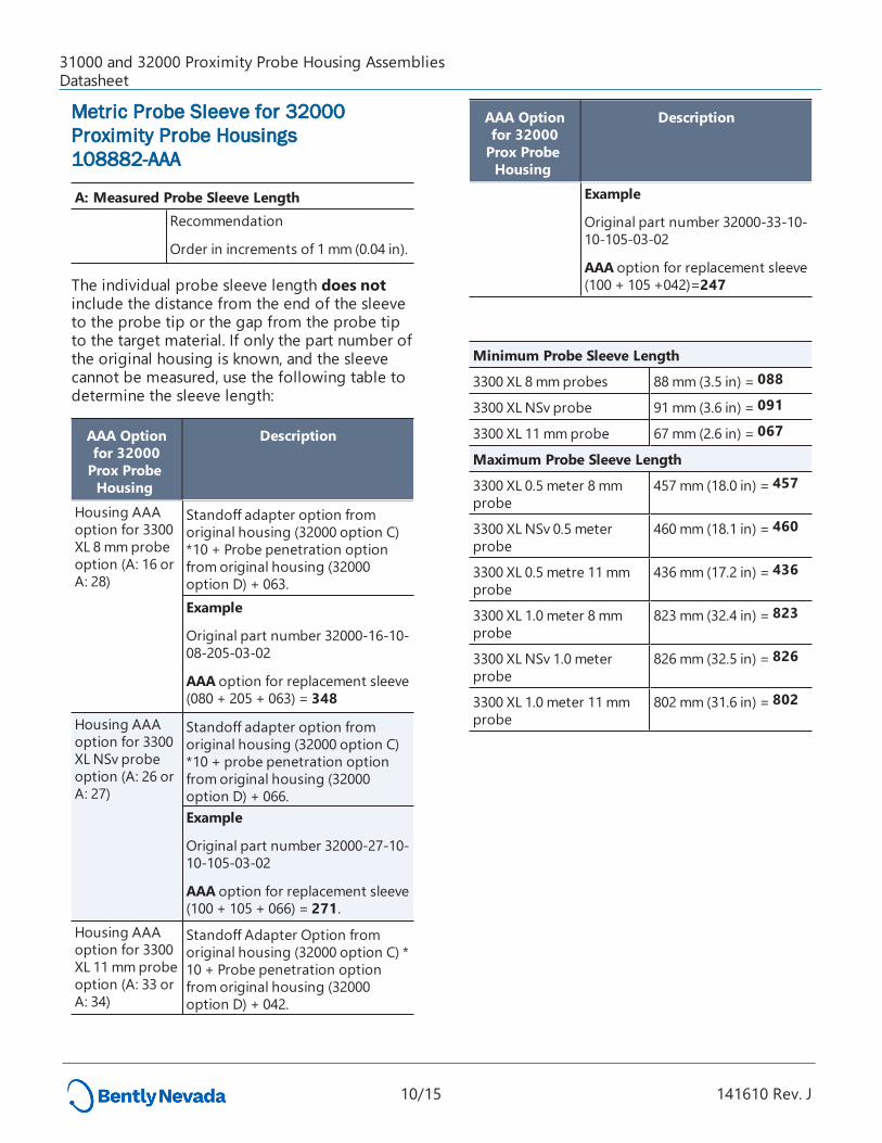
Metric Probe Sleeve for 32000Proximity Probe Housings108882-AAA
A: Measured Probe Sleeve LengthRecommendation
Order in increments of 1 mm (0.04 in).
The individual probe sleeve length does notinclude the distance from the end of the sleeveto the probe tip or the gap from the probe tipto the target material. If only the part number ofthe original housing is known, and the sleevecannot be measured, use the following table todetermine the sleeve length:
AAA Optionfor 32000Prox ProbeHousing
Description
Housing AAAoption for 3300XL 8 mmprobeoption (A: 16 orA: 28)
Standoff adapter option fromoriginal housing (32000 option C)*10 + Probe penetration optionfrom original housing (32000option D) + 063.Example
Original part number 32000-16-10-08-205-03-02
AAA option for replacement sleeve(080 + 205 + 063) = 348
Housing AAAoption for 3300XL NSv probeoption (A: 26 orA: 27)
Standoff adapter option fromoriginal housing (32000 option C)*10 + probe penetration optionfrom original housing (32000option D) + 066.Example
Original part number 32000-27-10-10-105-03-02
AAA option for replacement sleeve(100 + 105 + 066) = 271.
Housing AAAoption for 3300XL 11 mmprobeoption (A: 33 orA: 34)
Standoff Adapter Option fromoriginal housing (32000 option C) *10 + Probe penetration optionfrom original housing (32000option D) + 042.
AAA Optionfor 32000Prox ProbeHousing
Description
Example
Original part number 32000-33-10-10-105-03-02
AAA option for replacement sleeve(100 + 105 +042)=247
Minimum Probe Sleeve Length
3300 XL 8 mmprobes 88 mm (3.5 in) = 088
3300 XL NSv probe 91 mm (3.6 in) = 091
3300 XL 11 mmprobe 67 mm (2.6 in) = 067
Maximum Probe Sleeve Length
3300 XL 0.5 meter 8 mmprobe
457 mm (18.0 in) = 457
3300 XL NSv 0.5 meterprobe
460 mm (18.1 in) = 460
3300 XL 0.5 metre 11 mmprobe
436 mm (17.2 in) = 436
3300 XL 1.0 meter 8 mmprobe
823 mm (32.4 in) = 823
3300 XL NSv 1.0 meterprobe
826 mm (32.5 in) = 826
3300 XL 1.0 meter 11 mmprobe
802 mm (31.6 in) = 802
31000 and 32000 Proximity Probe Housing AssembliesDatasheet
10/15 141610 Rev. J

English Standoff Adaptor109319-AAA
A: Individual Standoff Adapter Length
Hex 1 3/8 in; threads = 3/4-14 NPT015 Minimum length 1.5 in (38 mm)075 Maximum length 7.5 in (191
mm)
Recommendation Order in increments of 0.5 in (13mm)
Metric Standoff Adaptor109318-AA
A: Individual Standoff Adapter Length
Wrench Flats 35 mm; threads = 3/4-14 NPT04 Minimum length 40 mm20 Maximum length 200 mm
Recommendation Order in increments of 10 mm
Example 120 mm= 12
For desired probe penetration lengths of lessthan 25 mm (1.0 in), order a separate IndividualStandoff Adapter.
The effective probe penetration length will then bereduced by the length of the Individual StandoffAdapter, plus an additional 13 mm (0.5 in) due to theNPT thread engagement.
Example:
To create a probe penetration length 13 mm (0.5in),order a 31000 housing with DDD (probe penetration)option of 030 [76 mm (3 in)] and a separate individualstandoff adapter that is 51 mm (2.0 in) in length (partnumber 21003-020).
The standoff adapter covers 38 mm (2.0 in) of theprobe sleeve plus an additional 13 mm (0.5 in).
Therefore, the effective probe penetration lengthdrops to 13 mm (0.5 in).
If you use effective penetration lengths of less than1.0 inches, signal effects are likely due to probe sideview or rear view of metal components.
Spare 3300 XL 8 mm Reverse MountProbe, 3/8-24 UNF threads
330105-02-12-CC-DD-EE
Spare 3300 XL 8 mm Reverse MountProbe, M10 X1 threads
330106-05-30-CC-DD-EE
A: Total Length
05 0.5 meter (1.6 feet)
10 1.0 meter (3.3 feet)
15 1.5 meter (4.9 feet)
20 2.0 meters (6.6 feet)
50 5.0 meters (16.4 feet)
90 9.0 meters (29.5 feet)
B: Connector
00 Connector not installed
02 Miniature ClickLoc coaxial connector
Agency Approval
00 Not required
05 Multiple approvals
31000 and 32000 Proximity Probe Housing AssembliesDatasheet
11/15 141610 Rev. J

Spare 3300 NSV Reverse MountProbe, 3/8-24 UNF threads
330906-02-12-CC-DD-EE
Spare 3300 NSV Reverse MountProbe, M10 X1 threads
330907-05-30-CC-DD-EE
C: Total Length
05 0.5 meter (1.6 feet)
10 1.0 meter (3.3 feet)
50 5.0 meters (16.4 feet)
90 9.0 meters (29.5 feet)
D: Connector
00 Connector not installed
02 Miniature ClickLoc coaxial connector
E: Agency Approval
00 Not required
05 Multiple approvals
Sleeve and Blanking Plugs
104968-01 English Sleeve Plug, threaded,303 stainless steel
104968-02 Metric Sleeve Plug, threaded,303 stainless steel.
Plugs fill opening when sleeve is removed frommachine case.
104288-01 English Blanking Plug
104288-02 Metric Blanking Plug
Plugs fill extra holes in plastic housing whereneeded.
Heavy Duty Conduit and Cable Fittings
03813103 Chrome-plated Zinc Conduit Fitting, 3/4-14 NPT
03818100 AISI 316 Stainless Steel Conduit Fitting,3/4-14 NPT
03818101 AISI 316 Stainless Steel Conduit Fitting,PG21 x M25
03818102 AISI 316 Stainless Steel Conduit Fitting,PG21 x M20
03818103 AISI 316 Stainless Steel Conduit Fitting,PG21 x PG11
03818104 AISI 303 Stainless Steel Cable Gland, PG11
03818105 AISI 316 Stainless Steel Cable Gland, M20
03818111 Nickel-plated Brass Conduit Fitting, PG21x M20
26650-01 AISI 303 Stainless Steel Reducer, 3/4-14NPT to 1/2-14 NPT
31000 and 32000 Proximity Probe Housing AssembliesDatasheet
12/15 141610 Rev. J

Graphs and Figures
Figure 1: Dimensions for 31000 and 32000 Proximity Probe Housings
Dimensions are in millimeters (inches).
13/15 141610 Rev. J
31000 and 32000 Proximity Probe Housing AssembliesDatasheet

All 4 holes in housing base, 1 per side, will accept sleeve or conduit fittings and cable glands.Fittings are supplied with housing depending on English, metric or DIN type.Hole plugs are provided to seal unused holes.
Installation Procedures
1. Install outer sleeve into machine case.2. Insert probe sleeve and adjust probe gap.3. Disconnect probe cable and fit housing over outer sleeve.4. Slide retainer under retaining nut. Tighten nut.5. Re-connect probe cable and Connector Protector.6. Place housing cover on housing and tighten captive screws.7. If hole plugs are used, tighten hole plug nuts to 0.5 N-m (5 in-lbs).
Figure 2: Vertical and Horizontal Profile Views of the 31000 and 32000 ProximityProbe Housings
14/15 141610 Rev. J
31000 and 32000 Proximity Probe Housing AssembliesDatasheet

Copyright 2019 Baker Hughes, a GE company, LLC ("BHGE") All rights reserved.
Bently Nevada, Orbit Logo, Keyphasor and Proximitor are registered trademarks of BHGE in the UnitedStates and other countries. All product and company names are trademarks of their respective holders.Use of the trademarks does not imply any affiliation with or endorsement by the respective holders.
This product may be covered by one or more patents, see Bently.com/legal for current status.The information contained in this document is subject to change without prior notice.
1631 Bently Parkway South, Minden, Nevada USA 89423Phone: 1.775.782.3611 Bently.com
15/15 141610 Rev. J
31000 and 32000 Proximity Probe Housing AssembliesDatasheet