Embed Size (px)
Citation preview
FCC ID: NCT048L10 IC: 2802A-048L10
CE 0678
WARRANTY INMOTION Controls, Inc. guarantees that this product meets its published
specification at the time of shipment from the factory. Under proper installation, it
should work as expected. However, INMOTION Controls, Inc. does not guarantee
that operation of the 310 Series Radio Control System is error-free or without
interruption.
This equipment is warranted against defects in materials and workmanship for a
period of one year from the date of shipment. During the warranty period,
INMOTION Controls, Inc. is responsible for necessary repairs, as long as the
product can be proved to be defective.
For warranty service or repair, this product must be returned to our factory.
Customer is responsible for shipping charges to INMOTION Controls, Inc., while
INMOTION Controls, Inc. will pay return shipping charges.
This warranty does NOT include consumable parts, such as joystick, batteries,
fuses, buttons, and relays or damage from normal wear and tear. Furthermore, this
warranty does NOT cover defects caused by misuse, neglect, accident, failure to
follow instructions, improper installation, improper or insufficient maintenance,
unauthorized modification, unsuitable operating environment, improper operation,
ignorance of environmental specifications, improper software/interfacing, fire, or
acts of God.
• No other warranty is expressed or implied, except for the above
mentioned
• The remedies provided herein are the buyers’ sole and exclusive
remedies.
• INMOTION Controls, Inc. shall not be liable for any direct/indirect,
special, incidental or consequential damages.
1
OPERATING PRECAUTIONS ATTENTION
• Due to the complex nature of the equipment, it is necessary
to read the entire manual before installation.
• Never dismantle equipment by any unauthorized personnel,
or equipment may be damaged.
• This Manual is for reference only; please call your distributor
if further assistance is required.
• This equipment has been strictly tested for quality before
delivery from our factory. However, it must not be used
in extremely dangerous situations, or where damage may
result.
• After operating, please shut off main power in Crane and the
power to Receiver.
• Transmitter should be placed safely when not in use to avoid
accidental pressing of buttons.
• The Crane should be equipped with main power Relay, Limit
Switch and other required safety devices.
• The GND (ground) of Receiver must be connected with metal
part of Crane, or electrical shock will occur.
• Do not use this device during electrical storm, or high
electrical interference conditions.
• Ensure Transmitter batteries are in good condition and power
for Receiver is normal.
• Installation and maintenance should be done only while the
Crane’s main power and Receiver’s power are OFF, to
prevent electrical shock.
• Contents of the Manual may be amended by the
manufacturer without notice.
2
PRECAUTIONS
• After Operating Series 310, please press EMO (Emergency Off)
mushroom and turn the keyswich to the “Off” to shut off main
power in the Crane & Receiver.
• Stop operating when slow-response occurs due to insufficient
Transmitter power, beyond the remote control range, or severe
interference.
• Remove the batteries when the equipment won’t be used for a long
period.
• Operators must be in good health and have good judgment in regards
to safety.
• Remote Control operator must have adequate training and related
license to avoid danger.
• Series 310 Transmitter is durable and weather-resistant, but care
should be taken not to subject it to severe impact or pressure.
• Series 310 is suitable for use in diverse industrial environments, and
adequate operating and maintenance will extend system’s life.
• Check EMO mushroom and the other security functions of Series
310 system before daily operation.
• Press EMO mushroom when malfunctions or abnormal conditions
occur.
• Operator must be familiar with the following Emergency Procedures before operating.
3
EMERGENCY PROCEDURES In case of emergency, please follow the steps below and ask the distributor
for service immediately.
• Press EMO mushroom
• Remove the batteries
• Shut off the main power of the Crane and discontinue the
operation
Contact the distributor to find out possible causes.
4

STANDARD ACCESSORIES A standard and full set of Series 310 consists of:
(1) Transmitter, 2 units (2) Receiver, 1 unit
Note:
Inmotion Series 310 Shown. Models vary depending on options.
5
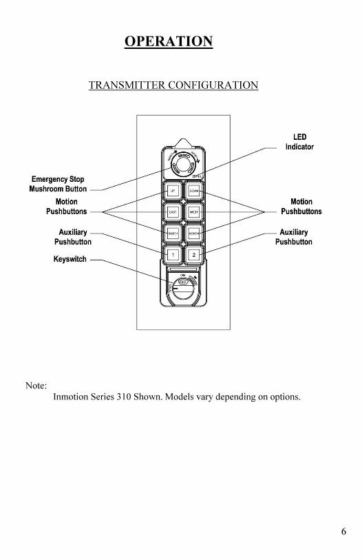
OPERATION
TRANSMITTER CONFIGURATION
Note:
Inmotion Series 310 Shown. Models vary depending on options.
6
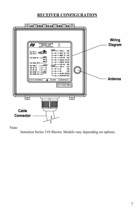
RECEIVER CONFIGURATION
Note:
Inmotion Series 310 Shown. Models vary depending on options.
7
GENERAL OPERATION
• Turn on the main power switch of the equipment (Crane).
• Install 2 AA batteries in the battery box in the Transmitter.
Make sure the polarity is correct.
• Attach Transmitter battery door with screws.
• Insert security key in the “OFF’ position.
• Turn the keyswitch clockwise to the “ON” position, then continue
to turn it to the “START” position to power-on.
Note: LED indicator will flash red if proper procedures are
not followed.
• Operate Transmitter by pressing each pushbutton.
• After operation, perform the following procedures in sequence:
(1) Press EMO mushroom
(2) Turn the keyswitch to the “OFF” position. (3) Remove key and keep the transmitter in a safe place.
(4) Switch main power off to the equipment (Crane).
(5) Remove batteries if not used for a long period of time.
Note: Transmitter has power indicating functions with LED
display.
← “Green Color” – The LED will flash green when battery
power is sufficient.
→ “Red Color” – The LED will flash red when the power is
low.
• The operating distance will become shorter and
intermittent when the batteries are low.
• Replace with new batteries when battery power
is low.
! DO NOT USE RECHARGEABLE BATTERIES !
8
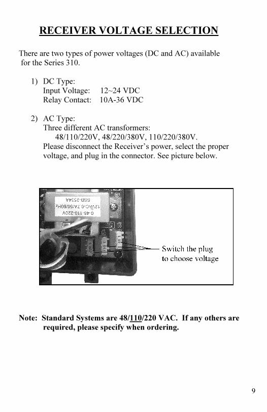
RECEIVER VOLTAGE SELECTION
There are two types of power voltages (DC and AC) available
for the Series 310.
1) DC Type: Input Voltage: 12~24 VDC
Relay Contact: 10A-36 VDC
2) AC Type: Three different AC transformers:
48/110/220V, 48/220/380V, 110/220/380V.
Please disconnect the Receiver’s power, select the proper
voltage, and plug in the connector. See picture below.
Note: Standard Systems are 48/110/220 VAC. If any others are
required, please specify when ordering.
9
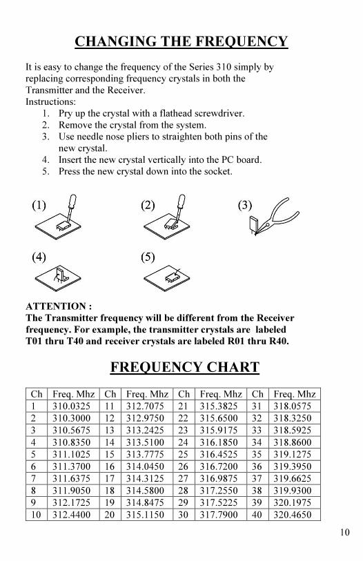
CHANGING THE FREQUENCY
It is easy to change the frequency of the Series 310 simply by
replacing corresponding frequency crystals in both the
Transmitter and the Receiver.
Instructions:
1. Pry up the crystal with a flathead screwdriver.
2. Remove the crystal from the system.
3. Use needle nose pliers to straighten both pins of the
new crystal.
4. Insert the new crystal vertically into the PC board.
5. Press the new crystal down into the socket.
ATTENTION :
The Transmitter frequency will be different from the Receiver
frequency. For example, the transmitter crystals are labeled
T01 thru T40 and receiver crystals are labeled R01 thru R40.
FREQUENCY CHART Ch Freq. Mhz Ch Freq. Mhz Ch Freq. Mhz Ch Freq. Mhz
1 310.0325 11 312.7075 21 315.3825 31 318.0575
2 310.3000 12 312.9750 22 315.6500 32 318.3250
3 310.5675 13 313.2425 23 315.9175 33 318.5925
4 310.8350 14 313.5100 24 316.1850 34 318.8600
5 311.1025 15 313.7775 25 316.4525 35 319.1275
6 311.3700 16 314.0450 26 316.7200 36 319.3950
7 311.6375 17 314.3125 27 316.9875 37 319.6625
8 311.9050 18 314.5800 28 317.2550 38 319.9300
9 312.1725 19 314.8475 29 317.5225 39 320.1975
10 312.4400 20 315.1150 30 317.7900 40 320.4650
10

BATTERIES
Two AA size alkaline batteries are required for the Transmitter.
The LED will flash green when the battery power is sufficient.
The LED will flash red when the battery power is low.
• The operating distance will become shorter and intermittent
when the battery is low.
• Replace with new battery when battery power is low.
! DO NOT USE RECHARGEABLE BATTERIES !
11

INSTALLATION NOTES
12
13
14