Embed Size (px)
Citation preview
Oxyfuel Pathways
Rodney AllamConsultantAir Products PLC, UK
MIT Carbon Sequestration Forum VIIPathways to Lower Capture Costs
31 October – 1 November 2006Royal Sonesta Hotel, Cambridge, MA

2
Oxyfuel Technology for CO2Capture - Definition:
Fuel + oxygen + diluent (optional)Diluent can be H2O or CO2
– i.e. Flue gas recycleDiluent controls combustion temperature

3
Oxyfuel Technology for CO2Capture - Characteristics:
Minimises CO2 impurities– N2 and Ar from air ingress and oxygen
impurities– O2 excess from combustion
Within the combustor all impurity concentrations derived from coal are increased
– SO2/SO3, Hg, etc.Independent control of combustion temperature and excess oxygen level
4
Oxyfuel Applications
Coal-fired boiler for power generationOxyfuel gas turbineOxyfuel high pressure steam generator –Clean Energy SystemsAdvanced Zero Emission Power Plant –Norsk Hydro
5
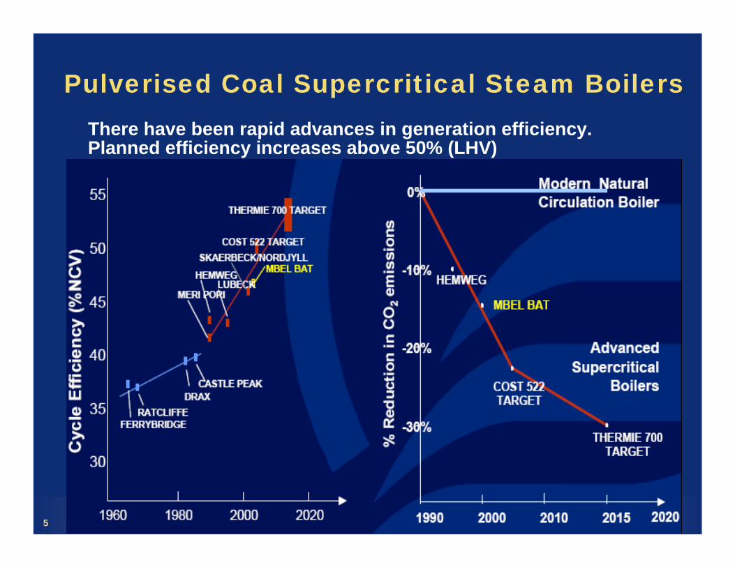
Pulverised Coal Supercritical Steam BoilersThere have been rapid advances in generation efficiency. Planned efficiency increases above 50% (LHV)
6
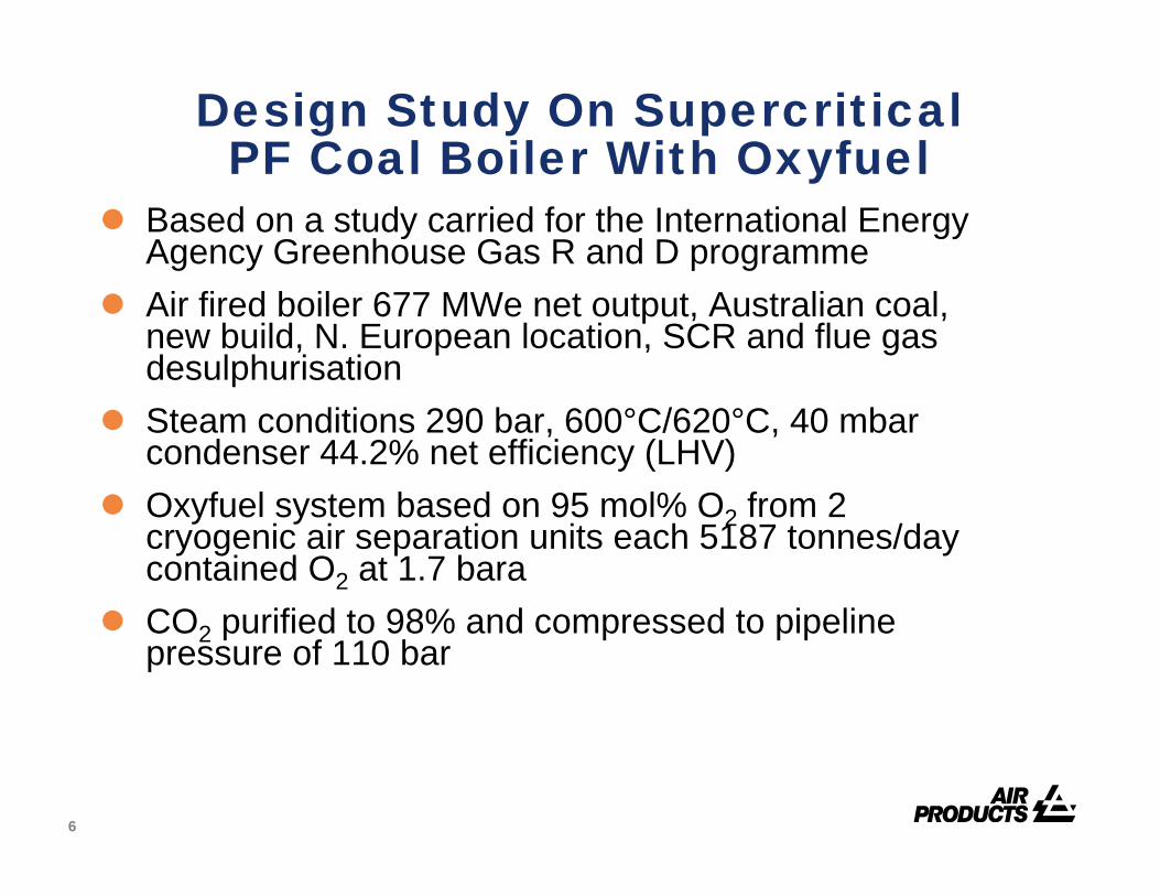
Design Study On Supercritical PF Coal Boiler With Oxyfuel
Based on a study carried for the International Energy Agency Greenhouse Gas R and D programmeAir fired boiler 677 MWe net output, Australian coal, new build, N. European location, SCR and flue gas desulphurisationSteam conditions 290 bar, 600°C/620°C, 40 mbar condenser 44.2% net efficiency (LHV)Oxyfuel system based on 95 mol% O2 from 2 cryogenic air separation units each 5187 tonnes/day contained O2 at 1.7 baraCO2 purified to 98% and compressed to pipeline pressure of 110 bar

7
Schematic of Supercritical PF OxyfuelPower Plant With CO2 Capture
1 - IP STEAM BLEED2 - HEAT FROM ASU ADIABATIC MAC3 - CO2 COMPRESSOR STAGE HEAT 4 – FLUE GAS FEEDWATER HEATING
HP HEATER
3
HP PUMP
LP HEATER
DEAERATOR
HP
IP
LP
CONDENSOR
LP PUMP
4
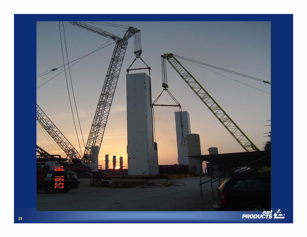
1 2 3 4
PRIMARY RECYCLE
COLD PA FAN
(START
SECONDARY RECYCLE
FD / RECYCLE
FAN
AIRINTAKE
UP)
OXYGEN
COAL
NITROGEN
AIR
ASU
MILL
2
ASC PF Oxy-Combustion Boiler
GAS/
GASHEATER
ID FAN
CO2 PURIFICATION
GAS COOLER & WATER REMOVAL
GAS DRIER
CO2 PRODUCT FOR COMPRESSION
INERTS
(START
43
3
ESP
8
1 - IP STEAM BLEED2 - HEAT FROM ASU ADIABATIC MAC3 - CO2 COMPRESSOR STAGE HEAT 4 – FLUE GAS FEEDWATER HEATING
HP HEATER
3
HP PUMP
LP HEATER
DEAERATOR
HP
IP
LP
CONDENSOR
LP PUMP
4
1 2 3 4
PRIMARY RECYCLE
COLD PA FAN
(START
SECONDARY RECYCLE
FD / RECYCLE
FAN
AIRINTAKE
UP)
OXYGEN
COAL
NITROGEN
AIR
ASU
MILL
2
ASC PF Oxy-Combustion Boiler
GAS/
GASHEATER
ID FAN
CO2 PURIFICATION
GAS COOLER & WATER REMOVAL
GAS DRIER
CO2 PRODUCT FOR COMPRESSION
INERTS
(START
43
3
ESP
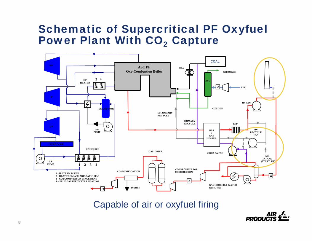
Schematic of Supercritical PF OxyfuelPower Plant With CO2 Capture
Capable of air or oxyfuel firing
9
1 - IP STEAM BLEED2 - HEAT FROM ASU ADIABATIC MAC3 - CO2 COMPRESSOR STAGE HEAT 4 – FLUE GAS FEEDWATER HEATING
HP HEATER
3
HP PUMP
LP HEATER
DEAERATOR
HP
IP
LP
CONDENSOR
LP PUMP
4
1 2 3 4
PRIMARY RECYCLE
COLD PA FAN
(START
SECONDARY RECYCLE
FD / RECYCLE
FAN
AIRINTAKE
UP)
OXYGEN
COAL
NITROGEN
AIR
ASU
MILL
2
ASC PF Oxy-Combustion Boiler
GAS/
GASHEATER
ID FAN
CO2 PURIFICATION
GAS COOLER & WATER REMOVAL
GAS DRIER
CO2 PRODUCT FOR COMPRESSION
INERTS
(START
43
3
ESP
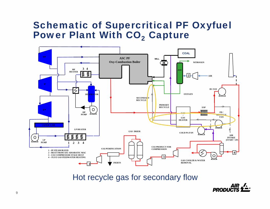
Schematic of Supercritical PF OxyfuelPower Plant With CO2 Capture
Hot recycle gas for secondary flow
10
1 - IP STEAM BLEED2 - HEAT FROM ASU ADIABATIC MAC3 - CO2 COMPRESSOR STAGE HEAT 4 – FLUE GAS FEEDWATER HEATING
HP HEATER
3
HP PUMP
LP HEATER
DEAERATOR
HP
IP
LP
CONDENSOR
LP PUMP
4
1 2 3 4
PRIMARY RECYCLE
COLD PA FAN
(START
SECONDARY RECYCLE
FD / RECYCLE
FAN
AIRINTAKE
UP)
OXYGEN
COAL
NITROGEN
AIR
ASU
MILL
2
ASC PF Oxy-Combustion Boiler
GAS/
GASHEATER
ID FAN
CO2 PURIFICATION
GAS COOLER & WATER REMOVAL
GAS DRIER
CO2 PRODUCT FOR COMPRESSION
INERTS
(START
43
3
ESP
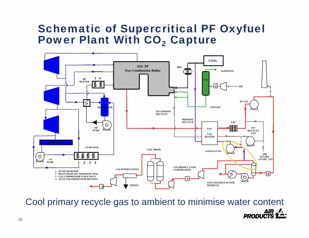
Schematic of Supercritical PF OxyfuelPower Plant With CO2 Capture
Cool primary recycle gas to ambient to minimise water content

11
1 - IP STEAM BLEED2 - HEAT FROM ASU ADIABATIC MAC3 - CO2 COMPRESSOR STAGE HEAT 4 – FLUE GAS FEEDWATER HEATING
HP HEATER
3
HP PUMP
LP HEATER
DEAERATOR
HP
IP
LP
CONDENSOR
LP PUMP
4
1 2 3 4
PRIMARY RECYCLE
COLD PA FAN
(START
SECONDARY RECYCLE
FD / RECYCLE
FAN
AIRINTAKE
UP)
OXYGEN
COAL
NITROGEN
AIR
ASU
MILL
2
ASC PF Oxy-Combustion Boiler
GAS/
GASHEATER
ID FAN
CO2 PURIFICATION
GAS COOLER & WATER REMOVAL
GAS DRIER
CO2 PRODUCT FOR COMPRESSION
INERTS
(START
43
3
ESP
Schematic of Supercritical PF OxyfuelPower Plant With CO2 Capture
Heat primary gas and pass through coal mill
12
1 - IP STEAM BLEED2 - HEAT FROM ASU ADIABATIC MAC3 - CO2 COMPRESSOR STAGE HEAT 4 – FLUE GAS FEEDWATER HEATING
HP HEATER
3
HP PUMP
LP HEATER
DEAERATOR
HP
IP
LP
CONDENSOR
LP PUMP
4
1 2 3 4
PRIMARY RECYCLE
COLD PA FAN
(START
SECONDARY RECYCLE
FD / RECYCLE
FAN
AIRINTAKE
UP)
OXYGEN
COAL
NITROGEN
AIR
ASU
MILL
2
ASC PF Oxy-Combustion Boiler
GAS/
GASHEATER
ID FAN
CO2 PURIFICATION
GAS COOLER & WATER REMOVAL
GAS DRIER
CO2 PRODUCT FOR COMPRESSION
INERTS
(START
43
3
ESP
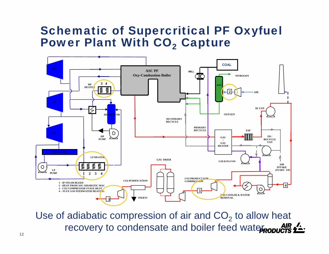
Schematic of Supercritical PF OxyfuelPower Plant With CO2 Capture
Use of adiabatic compression of air and CO2 to allow heat recovery to condensate and boiler feed water
13
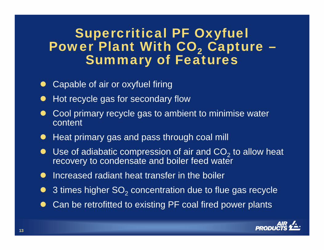
Supercritical PF OxyfuelPower Plant With CO2 Capture –
Summary of Features
Capable of air or oxyfuel firingHot recycle gas for secondary flowCool primary recycle gas to ambient to minimise water contentHeat primary gas and pass through coal millUse of adiabatic compression of air and CO2 to allow heat recovery to condensate and boiler feed waterIncreased radiant heat transfer in the boiler3 times higher SO2 concentration due to flue gas recycleCan be retrofitted to existing PF coal fired power plants
14
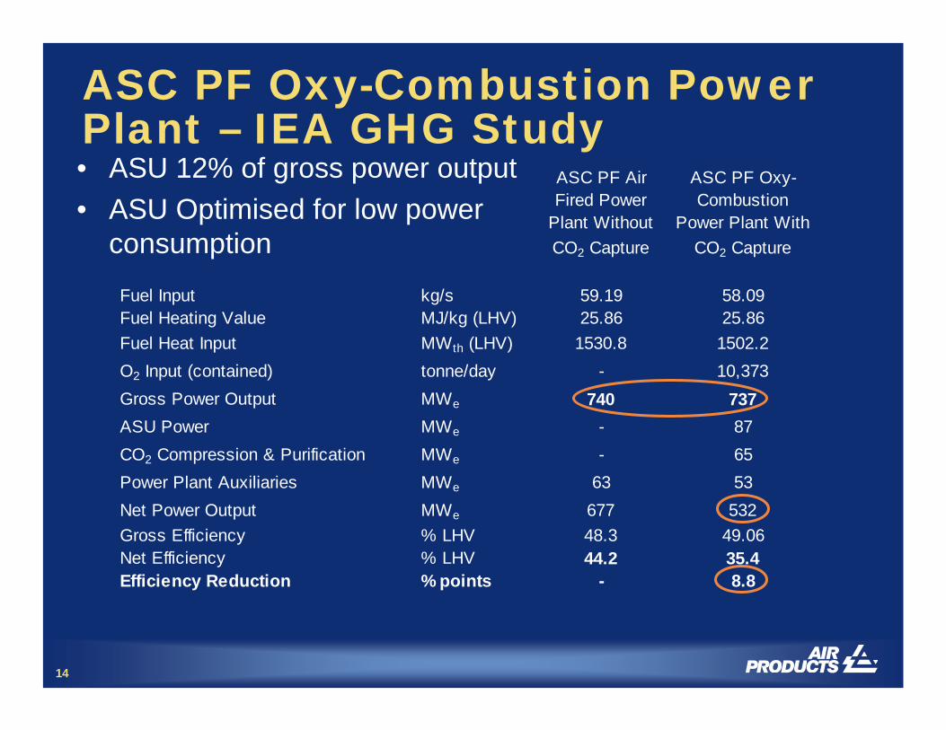
ASC PF Oxy-Combustion Power Plant – IEA GHG Study
ASC PF Air Fired Power
Plant Without CO2 Capture
ASC PF Oxy-Combustion
Power Plant With CO2 Capture
Fuel Input kg/s 59.19 58.09Fuel Heating Value MJ/kg (LHV) 25.86 25.86Fuel Heat Input MWth (LHV) 1530.8 1502.2O2 Input (contained) tonne/day - 10,373Gross Power Output MWe 740 737ASU Power MWe - 87CO2 Compression & Purification MWe - 65Power Plant Auxiliaries MWe 63 53Net Power Output MWe 677 532Gross Efficiency % LHV 48.3 49.06Net Efficiency % LHV 44.2 35.4Efficiency Reduction % points - 8.8
• ASU 12% of gross power output• ASU Optimised for low power
consumption

15
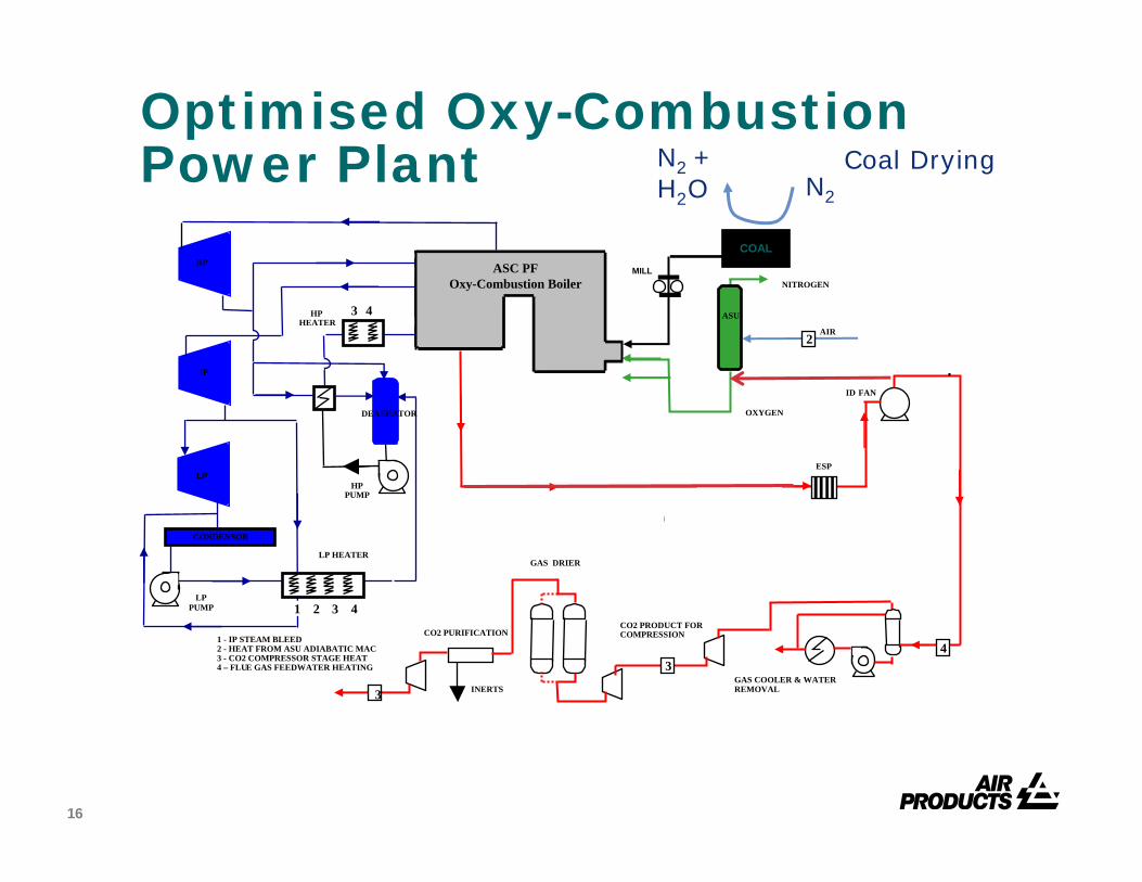
Optimised Oxy-Combustion Power Plant
1 - IP STEAM BLEED2 - HEAT FROM ASU ADIABATIC MAC3 - CO2 COMPRESSOR STAGE HEAT 4 – FLUE GAS FEEDWATER HEATING
HP HEATER
3
HP PUMP
LP HEATER
DEAERATOR
HP
IP
LP
CONDENSOR
LP PUMP
4
1 2 3 4
PRIMARY RECYCLE
COLD PA FAN
(START
SECONDARY RECYCLE
FD / RECYCLE
FAN
AIRINTAKE
UP)
OXYGEN
COAL
NITROGEN
AIR
ASU
MILL
2
ASC PF Oxy-Combustion Boiler
GAS/
GASHEATER
ID FAN
CO2 PURIFICATION
GAS COOLER & WATER REMOVAL
GAS DRIER
CO2 PRODUCT FOR COMPRESSION
INERTS
(START
43
3
ESP
Efficiency 35.6%
Only Hot Recycle
36.1% 36.3% 36.4% 36.6%
N2
N2 + H2O
Coal Drying
+ Coal Drying
Only Hot Recycle
+ O2 Preheat with IP Steam
123°C to 70°C
16
Optimised Oxy-Combustion Power Plant
1 - IP STEAM BLEED2 - HEAT FROM ASU ADIABATIC MAC3 - CO2 COMPRESSOR STAGE HEAT 4 – FLUE GAS FEEDWATER HEATING
HP HEATER
3
HP PUMP
LP HEATER
DEAERATOR
HP
IP
LP
CONDENSOR
LP PUMP
4
1 2 3 4
OXYGEN
COAL
NITROGEN
AIR
ASU
MILLASC PF Oxy-Combustion Boiler
GAS/
GASHEATER
ID FAN
CO2 PURIFICATION
GAS COOLER & WATER REMOVAL
GAS DRIER
CO2 PRODUCT FOR COMPRESSION
INERTS
(START
43
3
ESP
N2
N2 + H2O
Coal Drying
2

17
Optimised Oxyfuel Flowsheet
Design of the station for air and oxygen or oxygen alone Option for coal drying with dry nitrogen from the ASUAllows total hot gas recycle, removal of 2 blowers, gas-gas exchanger and improves efficiencyDust removal in a closed cycle oxyfuel system –options for ESP operation at higher temperatureFirst estimate for the duty of the boiler/steam turbine/auxiliary system following supercritical conversion. This will enable us to complete the overall process design of the oxyfuel and CO2compression system and its heat integration with the base case supercritical conversion project.
18
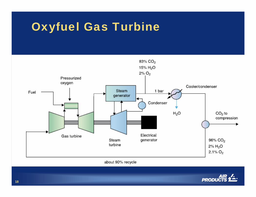
Oxyfuel Gas Turbine
19
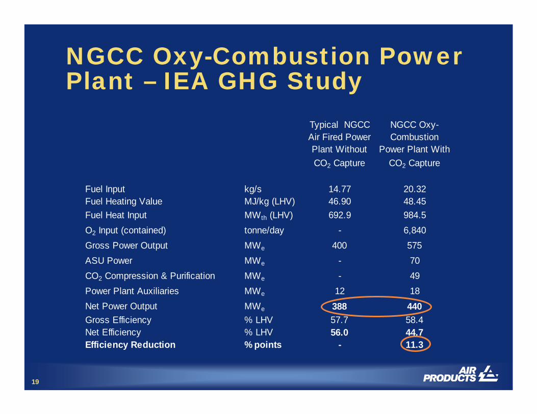
NGCC Oxy-Combustion Power Plant – IEA GHG Study
Typical NGCC Air Fired Power Plant Without CO2 Capture
NGCC Oxy-Combustion
Power Plant WithCO2 Capture
Fuel Input kg/s 14.77 20.32Fuel Heating Value MJ/kg (LHV) 46.90 48.45Fuel Heat Input MWth (LHV) 692.9 984.5O2 Input (contained) tonne/day - 6,840Gross Power Output MWe 400 575ASU Power MWe - 70CO2 Compression & Purification MWe - 49Power Plant Auxiliaries MWe 12 18Net Power Output MWe 388 440Gross Efficiency % LHV 57.7 58.4Net Efficiency % LHV 56.0 44.7Efficiency Reduction % points - 11.3
20
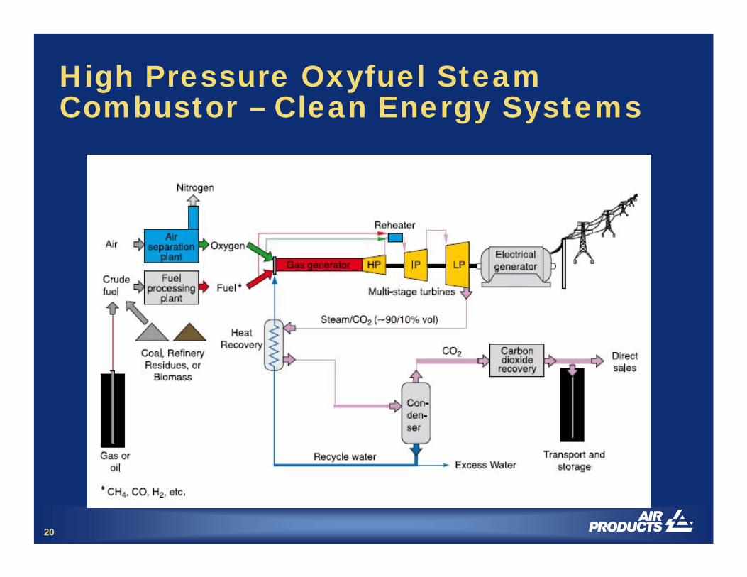
High Pressure Oxyfuel Steam Combustor – Clean Energy Systems
21
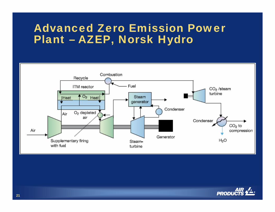
Advanced Zero Emission Power Plant – AZEP, Norsk Hydro
22
Purification of Oxyfuel-Derived CO2 for Sequestration or EOR
CO2 produced from oxyfuel requires purification
– Cooling to remove water– Inerts removal– Compression
Current design have limitations– SOx/NOx removal– Oxygen removal
A new concept for purification has been developed
– Includes SOx/NOx and oxygen removal
23
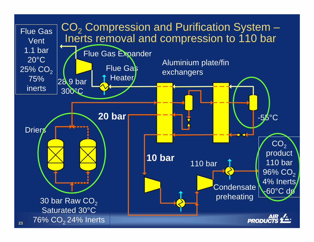
CO2 Compression and Purification System –Inerts removal and compression to 110 bar
Flue Gas ExpanderAluminium plate/fin exchangers
Driers
Condensate preheating
Flue GasHeater
20 bar
10 bar 110 bar
28.9 bar300°C
30 bar Raw CO2Saturated 30°C
76% CO2 24% Inerts
CO2product110 bar
96% CO24% Inerts-60°C dp
Flue Gas Vent
1.1 bar20°C
25% CO275% inerts
-55°C
24
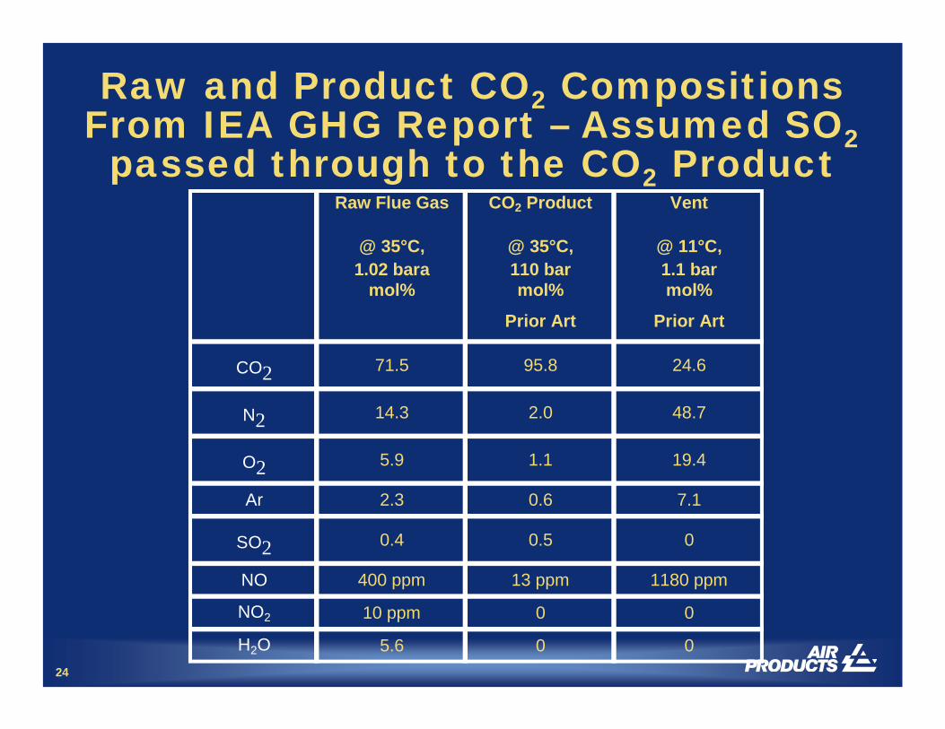
Raw and Product CO2 CompositionsFrom IEA GHG Report – Assumed SO2passed through to the CO2 Product
Raw Flue Gas CO2 Product Vent
@ 35°C, 1.02 bara
@ 35°C, 110 bar
@ 11°C, 1.1 bar
mol% mol% mol%
Prior Art Prior Art
CO2 71.5 95.8 24.6
N2 14.3 2.0 48.7
O2 5.9 1.1 19.4
Ar 2.3 0.6 7.1
SO2 0.4 0.5 0
NO 400 ppm 13 ppm 1180 ppm
NO2 10 ppm 0 0
H2O 5.6 0 0
25
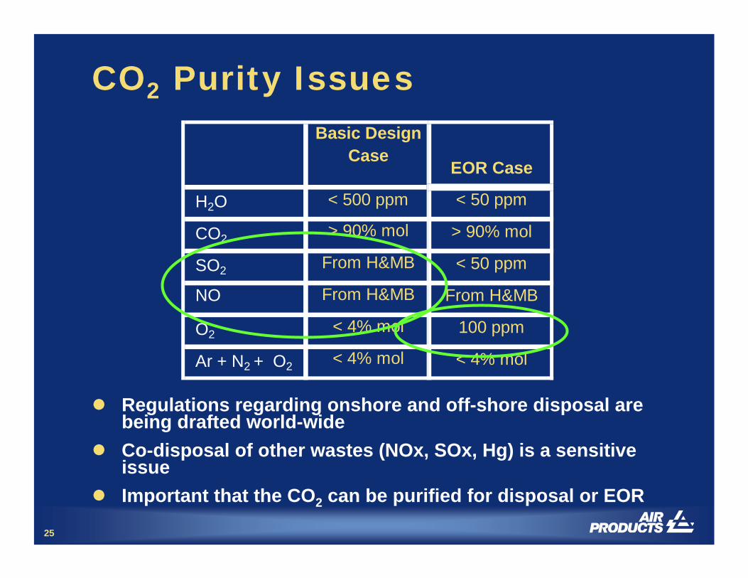
CO2 Purity IssuesBasic Design
Case
H2O < 500 ppm
CO2 > 90% mol
SO2 From H&MB
NO From H&MB
O2 < 4% mol
Ar + N2 + O2 < 4% mol
Regulations regarding onshore and off-shore disposal are being drafted world-wideCo-disposal of other wastes (NOx, SOx, Hg) is a sensitive issueImportant that the CO2 can be purified for disposal or EOR
EOR Case
< 50 ppm
> 90% mol
< 50 ppm
From H&MB
100 ppm
< 4% mol

26
NOx SO2 Reactions in the CO2Compression System
We realised that SO2, NOx and Hg can be removed in the CO2compression process, in the presence of water and oxygen. SO2 is converted to Sulphuric Acid, NO2 converted to Nitric Acid:
– NO + ½ O2 = NO2 (1) Slow– 2 NO2 = N2O4 (2) Fast– 2 NO2 + H2O = HNO2 + HNO3 (3) Slow– 3 HNO2 = HNO3 + 2 NO + H2O (4) Fast– NO2 + SO2 = NO + SO3 (5) Fast– SO3 + H2O = H2SO4 (6) Fast
Rate of Reaction 1 increases with Pressure to the 3rd power– only feasible at elevated pressure
No Nitric Acid is formed until all the SO2 is convertedPressure, reactor design and residence times, and NO concentration are important

27
CO2 Compression and Purification System –Removal of SO2, NOx and Hg
1.02 bar 30°C
67% CO28% H2O
25% InertsSOxNOx
30 bar to DriersSaturated 30°C
76% CO224% Inerts
Dilute H2SO4 HNO3
Hg
SO2 removal: 100% NOx removal: 90-99%
BFW
Condensate
cw
15 bar 30 bar
Water
cwcw
Dilute HNO3
28
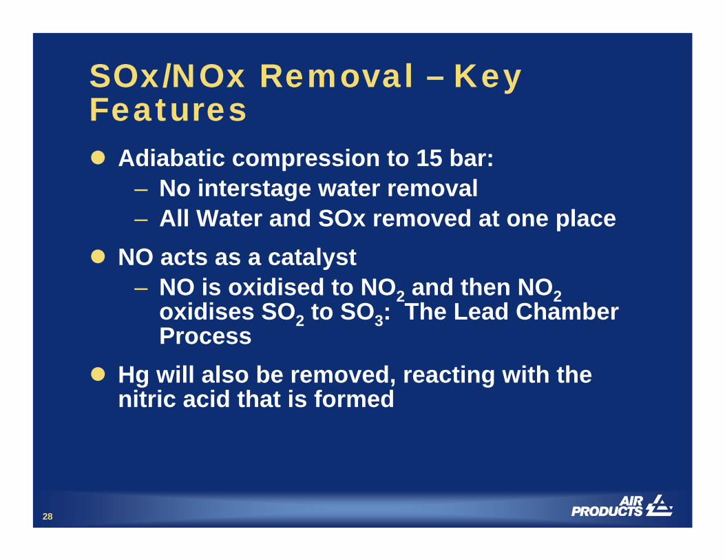
SOx/NOx Removal – Key Features
Adiabatic compression to 15 bar:– No interstage water removal– All Water and SOx removed at one place
NO acts as a catalyst– NO is oxidised to NO2 and then NO2
oxidises SO2 to SO3: The Lead Chamber Process
Hg will also be removed, reacting with the nitric acid that is formed
29
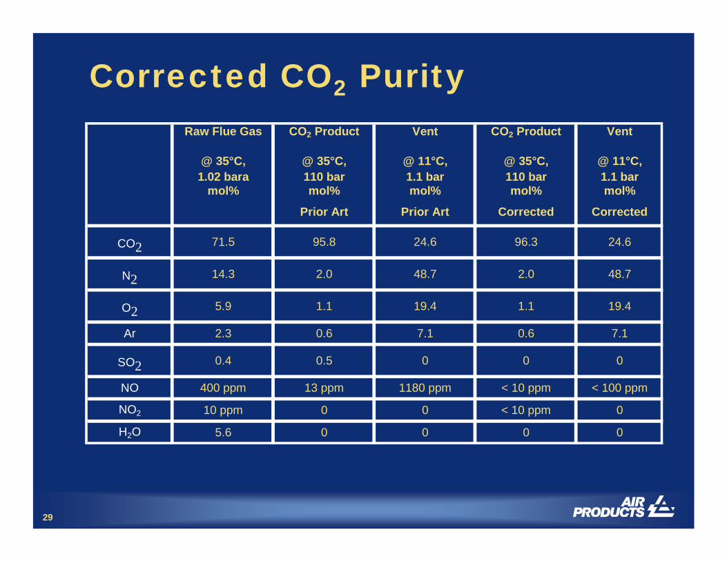
Corrected CO2 PurityRaw Flue Gas CO2 Product Vent CO2 Product Vent
@ 35°C, 1.02 bara
@ 35°C, 110 bar
@ 11°C, 1.1 bar
@ 35°C, 110 bar
@ 11°C, 1.1 bar
mol% mol% mol% mol% mol%
Prior Art Prior Art Corrected Corrected
CO2 71.5 95.8 24.6 96.3 24.6
N2 14.3 2.0 48.7 2.0 48.7
O2 5.9 1.1 19.4 1.1 19.4
Ar 2.3 0.6 7.1 0.6 7.1
SO2 0.4 0.5 0 0 0
NO 400 ppm 13 ppm 1180 ppm < 10 ppm < 100 ppm
NO2 10 ppm 0 0 < 10 ppm 0
H2O 5.6 0 0 0 0
30
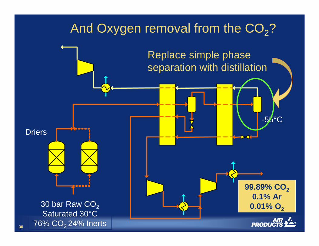
And Oxygen removal from the CO2?
Driers
30 bar Raw CO2Saturated 30°C
76% CO2 24% Inerts
-55°C
Replace simple phase separation with distillation
99.89% CO20.1% Ar
0.01% O2
31
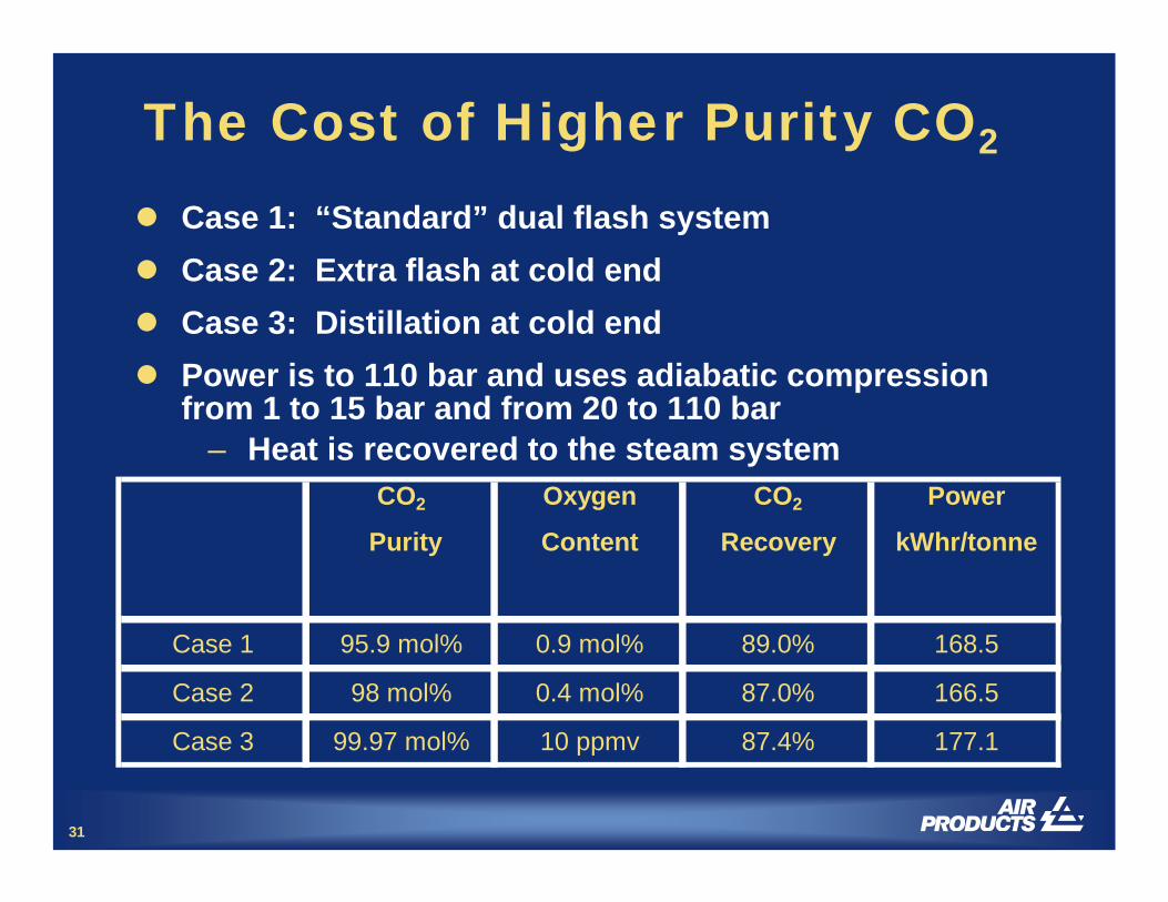
The Cost of Higher Purity CO2
Case 1: “Standard” dual flash systemCase 2: Extra flash at cold endCase 3: Distillation at cold endPower is to 110 bar and uses adiabatic compression from 1 to 15 bar and from 20 to 110 bar
– Heat is recovered to the steam systemCO2 Oxygen CO2 Power
Purity Content Recovery kWhr/tonne
Case 1 95.9 mol% 0.9 mol% 89.0% 168.5
Case 2 98 mol% 0.4 mol% 87.0% 166.5
Case 3 99.97 mol% 10 ppmv 87.4% 177.1
32
Summary of CO2 Purification
FGD and DeNOx systems are not required to meet tight CO2 purity specificationsCo-disposal of SO2 with CO2 is not possible
– Compressing CO2 with NO + SO2 + O2 + Water will result in H2SO4 production
Low NOx burners are not required for oxyfuelcombustionOxygen can be removed for EOR-grade CO2
Large-scale demonstration is required– Further development is planned
33
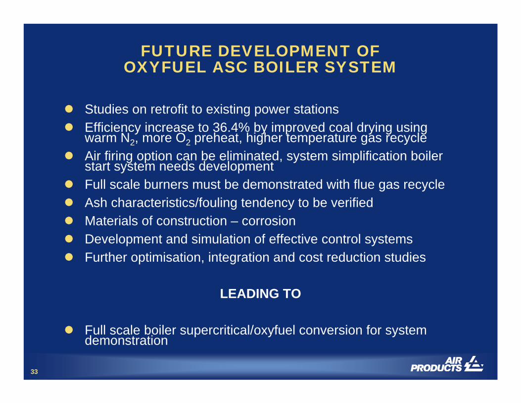
FUTURE DEVELOPMENT OF OXYFUEL ASC BOILER SYSTEM
Studies on retrofit to existing power stationsEfficiency increase to 36.4% by improved coal drying using warm N2, more O2 preheat, higher temperature gas recycleAir firing option can be eliminated, system simplification boiler start system needs developmentFull scale burners must be demonstrated with flue gas recycleAsh characteristics/fouling tendency to be verifiedMaterials of construction – corrosionDevelopment and simulation of effective control systemsFurther optimisation, integration and cost reduction studies
LEADING TO
Full scale boiler supercritical/oxyfuel conversion for system demonstration
34
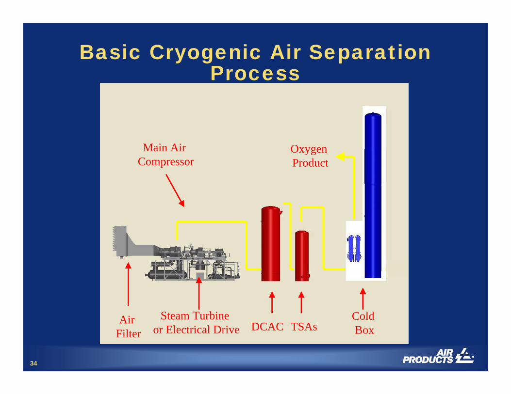
Basic Cryogenic Air Separation Process
Air Filter
Main Air Compressor
Steam Turbine or Electrical Drive DCAC TSAs
Cold Box
Oxygen Product
35
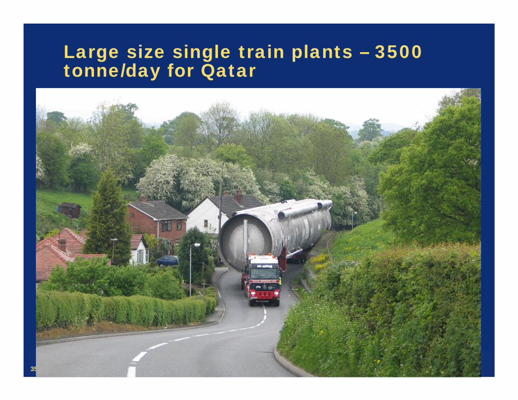
Large size single train plants – 3500 tonne/day for Qatar

36
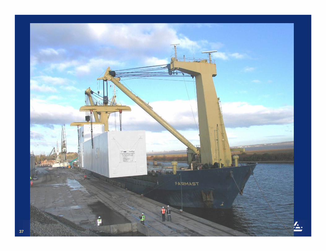
Prefabricated modularised design
37

38
39
40
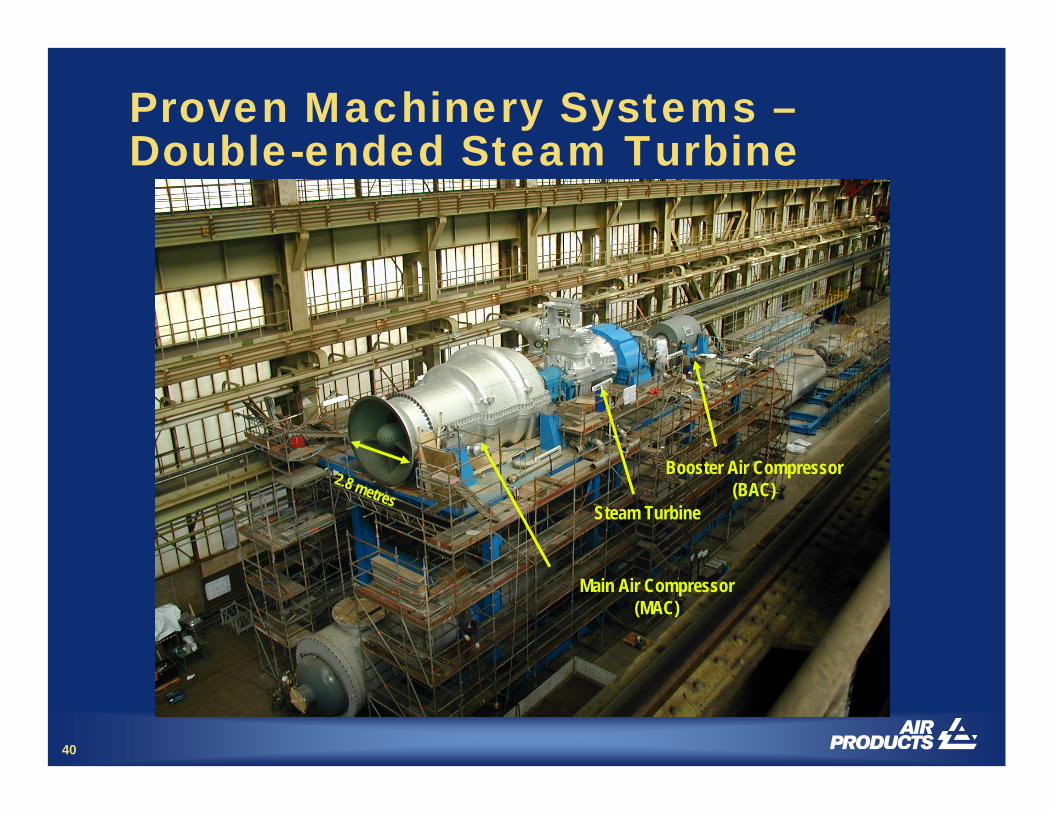
Proven Machinery Systems –Double-ended Steam Turbine
2.8 metres
Main Air Compressor(MAC)
Steam Turbine
Booster Air Compressor(BAC)

41
Ion Transport Membranes (ITM): High-flux, High-purity Oxygen
O2- electrons
compressed air
oxygen
P’
P’’O2
O2
O2- ½O2 + 2e-
½O2 + 2e- O2-
• Mixed-conducting ceramic membranes (non-porous)
• Typically operate at 800-900 °C
• Crystalline structure incorporatesoxygen ion vacancies
• Oxygen ions diffuse through vacancies
• 100% selective for O2
• ln1''2
'2
2 ⎟⎟⎠
⎞⎜⎜⎝
⎛∝
O
O
PP
LFluxO
L
42
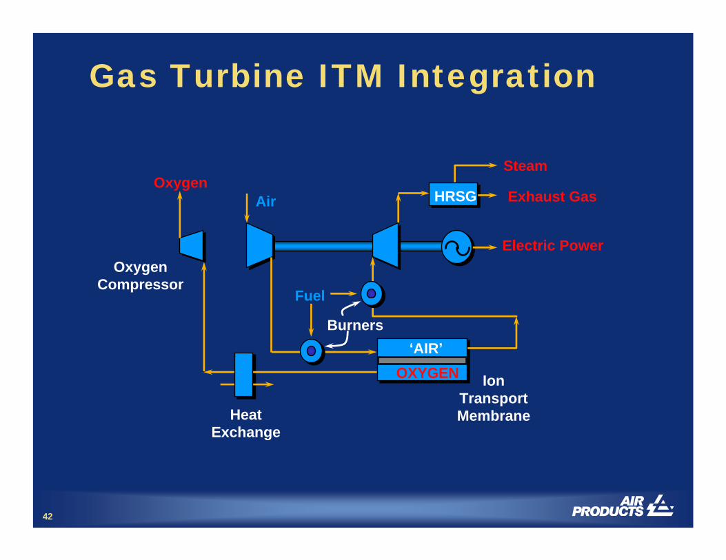
Gas Turbine ITM Integration
AirOxygen
Fuel
HeatExchange
IonTransportMembrane
HRSG
Steam
OxygenCompressor
Electric Power
OXYGEN‘AIR’
Burners
Exhaust Gas

43
Ion Transport Membrane For Low Cost Oxygen Production
vitiated compressed-air
Pure Oxygen
Thin membrane (A)
Porous membrane support (B)
Dense, slotted backbone (C)
Product withdrawal tube
Spacer ring800-900°C
15-20 bar
ABC
A
B
C

Thank you

tell me morewww.airproducts.com