Embed Size (px)
DESCRIPTION
GE HA Dryer Upgrade – GFDN240 SeriesGE® 7.0 cu. ft. stainless steel capacity dryer Models:
Citation preview
GWS2011
GE HA Dryer Upgrade – GFDS350 Series GE® 7.5 cu. ft. stainless steel capacity dryer with Steam Options
Models:GFDS350ELWWGFDS350GLWWGFDS355ELMV GFDS355GLMVGFDS355ELMSGFDS355GLMS
Service Guide31-9209

GWS2011
GE HA Dryer Upgrade – GFDN240 Series GE® 7.0 cu. ft. stainless steel capacity dryer
Models:GFDN240ELWWGFDN240GLWWGFDN245ELMS GFDN245GLMSGFDN245ELMV GFDN245GLMV
NOTE: 240 series is the same asthe 350 series but without steam & a slightly smaller drum.
Copyright 20113
IMPORTANT SAFETY NOTICEThe information in this presentation is intended for use by individuals possessing adequate backgrounds of electrical, electronic, & mechanical experience. Any attempt to repair a major appliance may result in personal injury & property damage. The manufacturer or seller cannot be responsible for the interpretation of this information, nor can it assume any liability in connection with its use.
WARNINGTo avoid personal injury, disconnect power before servicing this
product. If electrical power is required for diagnosis or test purposes, disconnect the power immediately after performing the necessary checks.
RECONNECT ALL GROUNDING DEVICESIf grounding wires, screws, straps, clips, nuts, or washers used
to complete a path to ground are removed for service, they must be returned to their original position & properly fastened.

Copyright 20114
GE Factory Service Employees are required to use safety glasses with side shields, safety gloves & steel toe shoes for all repairs.
Dyneema® Cut Resistant Glove Dyneema® Cut Resistant Glove
Safety Glasses must beANSI Z87.1-2003 compliantSafety Glasses must be
ANSI Z87.1-2003 compliant
Prescription Safety GlassesPrescription Safety Glasses
Plano Type Safety GlassesPlano Type Safety Glasses
Steel Toe Work Boot
Steel Toe Work Boot
Electrically Rated Glove and Dyneema® Cut
Resistant Glove Keeper
Electrically Rated Glove and Dyneema® Cut
Resistant Glove Keeper
Brazing GlassesBrazing Glasses

Copyright 20115
Warranty
Copyright 20116
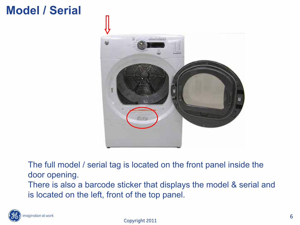
Model / Serial
The full model / serial tag is located on the front panel inside
thedoor opening.There is also a barcode sticker that displays the model & serial
andis located on the left, front of the top panel.
Copyright 20117
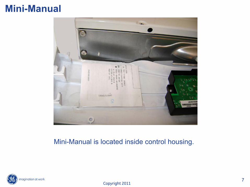
Mini-Manual
Mini-Manual is located inside control housing.
Copyright 20118
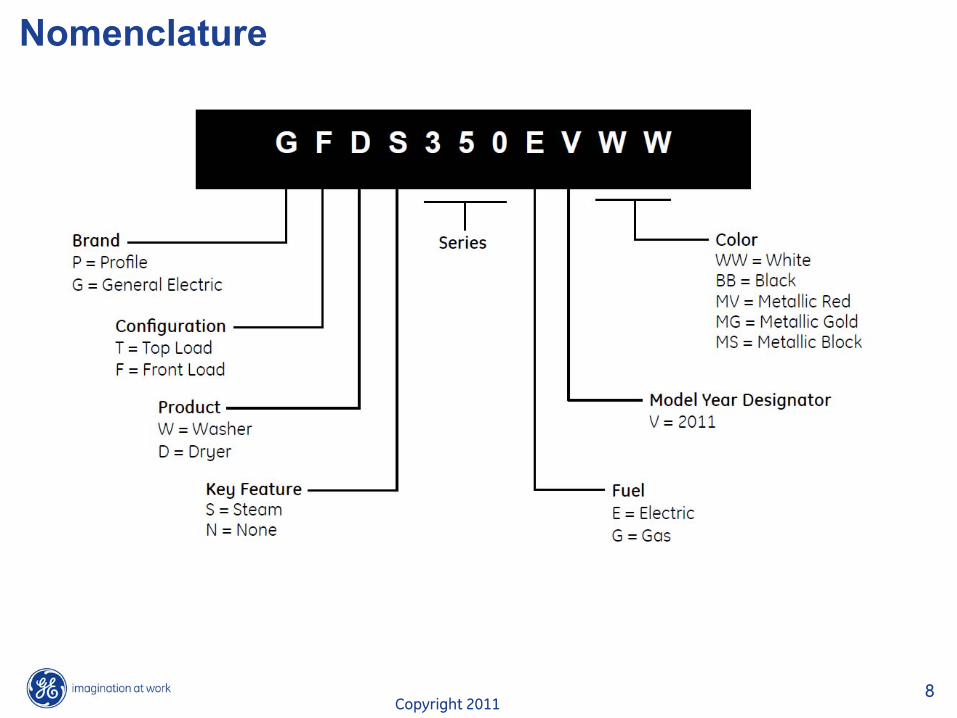
Nomenclature

Copyright 20119
InstallationThese Laundry products can be installedin several different configurations:
Undercounter
Side-by-Side.
Pedistal
Stacked
Dryer can be stacked on the washer.Kit for stacking dryer over washer is not included with the washer.Order GEFLSTACK.
Machines can be stacked on apedestal. These can be ordered separately.SPSD157JMV – VermillionSPSD157JMS - SilverSPSD157JWW - White
Adobe Acrobat Document
Stacking Instructions.Open in “Normal View”.
Copyright 201110
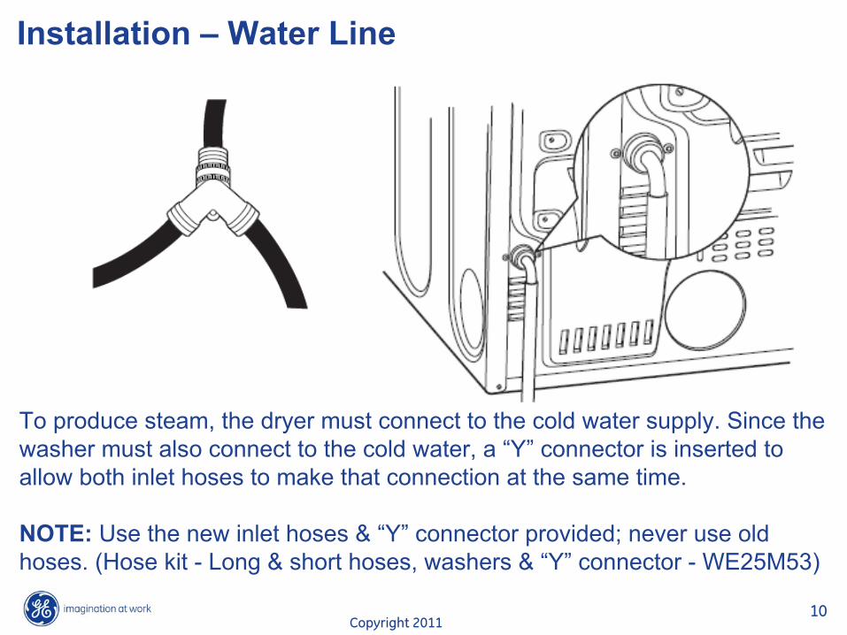
Installation – Water Line
To produce steam, the dryer must connect to the cold water supply. Since the washer must also connect to the cold water, a “Y”
connector is inserted to allow both inlet hoses to make that connection at the same time.
NOTE: Use the new inlet hoses & “Y”
connector provided; never use old hoses. (Hose kit -
Long & short hoses, washers & “Y”
connector -
WE25M53)

Copyright 201111
Installation - Venting
These dryer models can be vented through the rear, the side or the bottomof the cabinet.
STANDARD REAR EXHAUSTDryer Exhaust to the rear of cabinet for Gas and Electric models.
SIDE VENTING:Dryer Exhaust to right of cabinet for Electric models only.Dryer Exhaust to left of cabinet for Gas and Electric models.
BOTTOM VENTING:Dryer Exhaust to the bottom of cabinet for Gas and Electric models.

Copyright 201112
Installation – Demo Mode
To enter demo mode: Turn the unit off so the screen is blank. Then unplug the unit, wait 10 seconds.Plug the unit back in. Within 30 seconds after plugging in the unit, press the Start/Pausebutton 4 times within 3 seconds with the door open.
To exit Demo Mode: Repeat the above sequence.
Note: In the Demo Mode, the control will proceed through the selected cycle but will not actually activate any components.

Copyright 201113
Features – Steam CyclesSteam Refresh
For slightly wrinkled dry garments. Significantly reduces wrinkles on 1–5 garments.Selecting a higher number of garments for the cycle (e.g., selecting 5-
garment load for a 1-garment load) may result in excessive wetting of clothes. After the STEAM REFRESH Cycle, the unit will beep and display “Garments Ready”
and “0:00.”
If the unit is not turned off or if the door is not opened, the dryer will continue to tumble for 30 minutes. At the
end of 30 minutes, it will display “0:00”
and “Cycle Complete.”NOTE: When STEAM REFRESH is selected, “EXTENDED TUMBLE” will automatically turn on and cannot be turned off.
A single extremely light fabric item may need to have an additional item included in the steam refresh cycle toachieve optimum results.

Copyright 201114
Features – Steam CyclesSteam Dewrinkle
For use with larger loads than STEAM REFRESH. Ideal for loads left in dryer for an extended time. Selecting a larger cycle than needed (e.g., selecting Large Load for a half-full dryer)may result in excessive wetting of clothes.
Copyright 201115
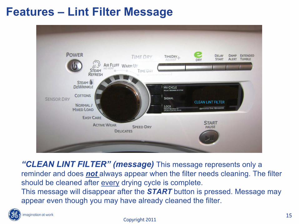
Features – Lint Filter Message
“CLEAN LINT FILTER” (message) This message represents only a reminder and does not always appear when the filter needs cleaning. The filter should be cleaned after every
drying cycle is complete.This message will disappear after the START button is pressed. Message may appear even though you may have already cleaned the filter.
Copyright 201116
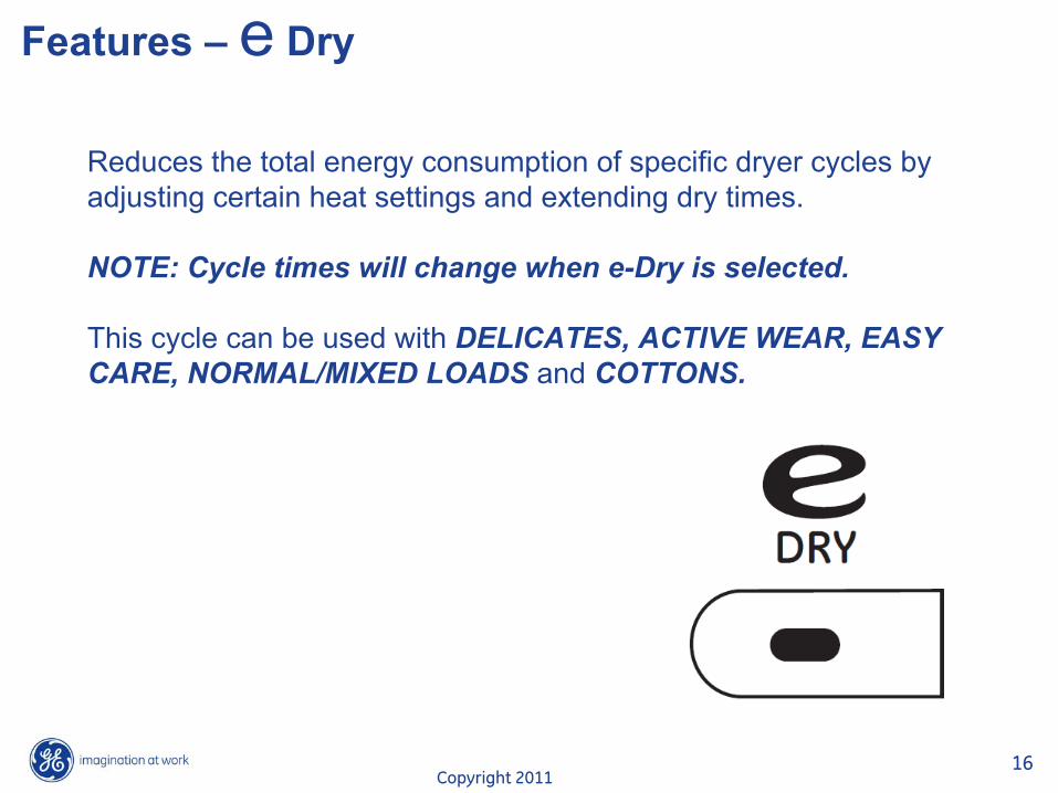
Features – e
Dry
Reduces the total energy consumption of specific dryer cycles by
adjusting certain heat settings and extending dry times.
NOTE: Cycle times will change when e-Dry is selected.
This cycle can be used with DELICATES, ACTIVE WEAR, EASY CARE, NORMAL/MIXED LOADS and COTTONS.

Copyright 201117
Features – Drying Rack
• The drying rack is designed for use with the TIMED DRY cycles.• Use with sensor cycles may result in damp items or extended cycle times.• Do not use this drying rack when there are other clothes in the
dryerthat are not placed on the rack.
Copyright 201118
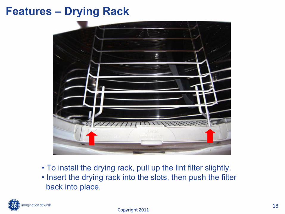
Features – Drying Rack
• To install the drying rack, pull up the lint filter slightly.• Insert the drying rack into the slots, then push the filterback into place.
Copyright 201119
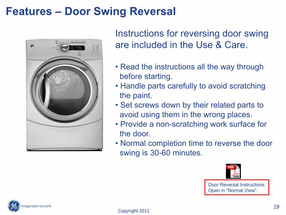
Features – Door Swing Reversal
Instructions for reversing door swingare included in the Use & Care.
• Read the instructions all the way throughbefore starting.
• Handle parts carefully to avoid scratchingthe paint.
• Set screws down by their related parts toavoid using them in the wrong places.
• Provide a non-scratching work surface forthe door.
• Normal completion time to reverse the doorswing is 30-60 minutes.
Adobe Acrobat Document
Door Reversal Instructions.Open in “Normal View”.

Copyright 201120
Disassembly – Top Panel
1. Remove the Phillips-head screw that attaches the control panel rear trim. Pull the trim piece backward and remove.Note: It may be helpful to place a putty knife along the top seam between the trim and the control panel, then tap lightly backward.

Copyright 201121
Disassembly – Top Panel
2. Remove the 2 Phillips-head screws that attach the top panel to the cabinet.3. Raise the front of the top panel approximately 3 inches, then
pull forward to clear the rear tabs. Lift off top panel.

Copyright 201122
Disassembly – Control Panel
Removal of the control panel provides access to thecontrol board assembly.
To remove the control panel:1. Remove the cycle selector knob by pulling outward.
Copyright 201123
Disassembly – Control Panel
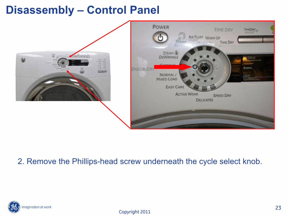
2. Remove the Phillips-head screw underneath the cycle select knob.
Copyright 201124
Disassembly – Control Panel
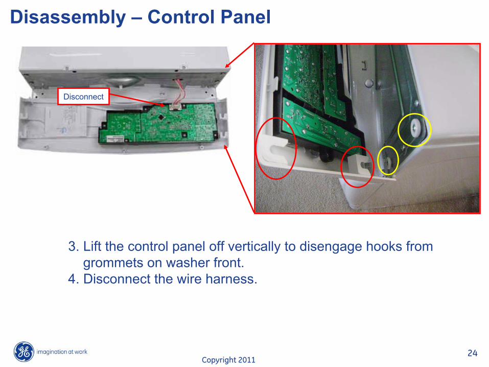
Disconnect
3. Lift the control panel off vertically to disengage hooks fromgrommets on washer front.
4. Disconnect the wire harness.

Copyright 201125
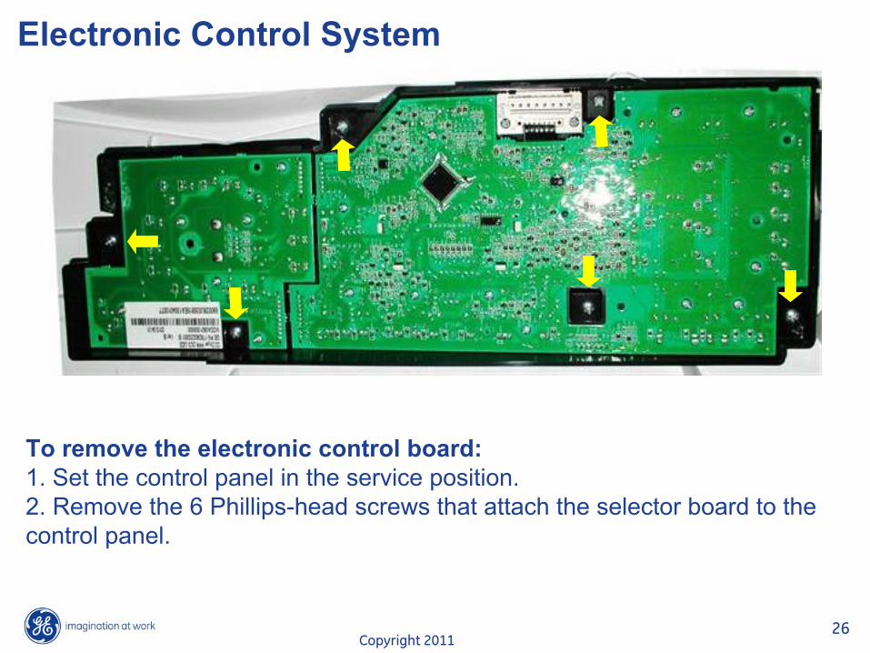
Electronic Control System
The electronic control consists of a control board (UI) and a power board.
Control Board
Power Board
Copyright 201126
Electronic Control System
To remove the electronic control board:1. Set the control panel in the service position. 2. Remove the 6 Phillips-head screws that attach the selector board to the control panel.

Copyright 201127
Electronic Control System
To remove the electronic power board:1. Remove the top panel. 2. Disconnect 11 wires and wiring harnesses from the power board.3. Remove the 2 Phillips-head screws to release the power board from the power board bracket.

Copyright 201128
Electronic Control System (Model Select plug)
Note: If replacing the electronic control, transfer the model selector
harness at J5, to the replacement control board in the same location as on the original.
J5 Model Select Plug
Copyright 201129
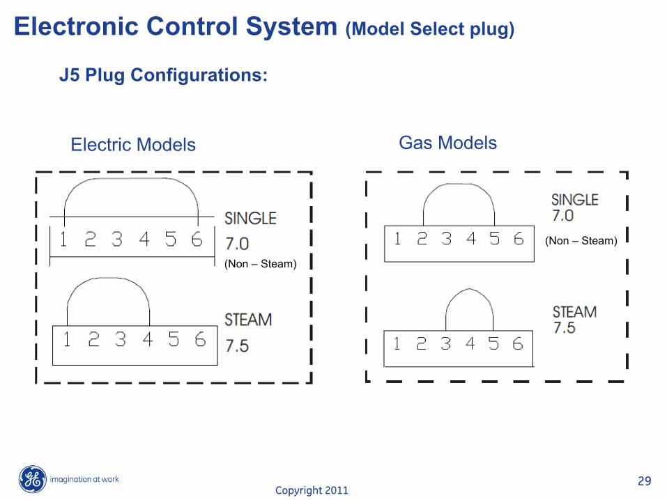
Electronic Control System (Model Select plug)
J5 Plug Configurations:
Electric Models Gas Models
(Non –
Steam)
(Non –
Steam)

Copyright 201130
Disassembly – Front Panel
To remove the front panel:1. Remove the top panel and control panel. 2. Disconnect the drum lamp / door switch wire harness and the sensor rod wire harness connected to the power board.3. Remove the 2 Phillips-head screws from the front panel bracket.4. Remove 4 Phillips-head screws from the front panel bracket.5. Lift the bracket out of the hinges and set aside.
Disconnect
Copyright 201131
Disassembly – Front Panel
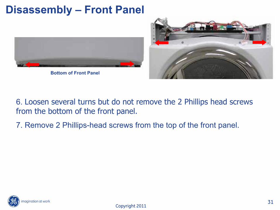
6. Loosen several turns but do not remove the 2 Phillips head screws from the bottom of the front panel.
7. Remove 2 Phillips-head screws from the top of the front panel.
Bottom of Front Panel

Copyright 201132
Disassembly – Front Panel
8. Tilt the top edge of the front panel out and press on the John Guest connector collar to release the water line.
9. Lift front panel from the bottom two screws and set aside.
Copyright 201133
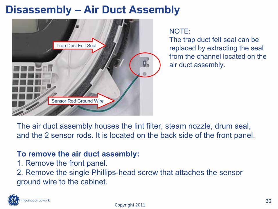
Disassembly – Air Duct Assembly
The air duct assembly houses the lint filter, steam nozzle, drum
seal, and the 2 sensor rods. It is located on the back side of the front panel.
To remove the air duct assembly:1. Remove the front panel. 2. Remove the single Phillips-head screw that attaches the sensor ground wire to the cabinet.
Sensor Rod Ground Wire
NOTE:The trap duct felt seal can be replaced by extracting the seal from the channel located on the air duct assembly.
Trap Duct Felt Seal
Copyright 201134
Disassembly – Air Duct Assembly
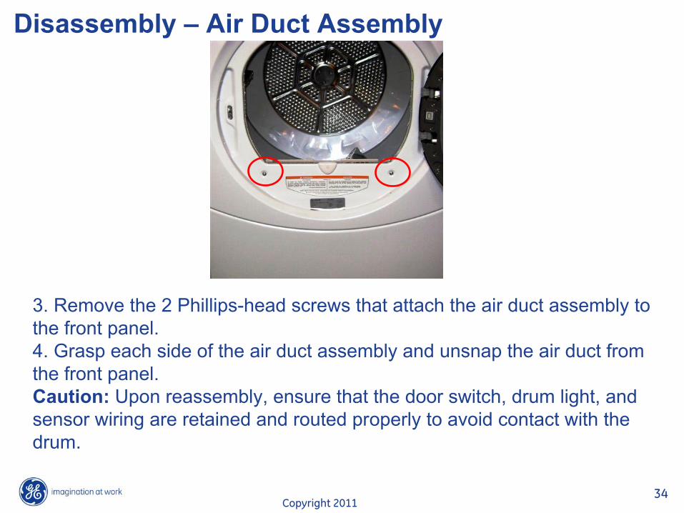
3. Remove the 2 Phillips-head screws that attach the air duct assembly to the front panel.4. Grasp each side of the air duct assembly and unsnap the air duct from the front panel.Caution: Upon reassembly, ensure that the door switch, drum light, and sensor wiring are retained and routed properly to avoid contact with the drum.
Copyright 201135
Disassembly – Air Duct Assembly
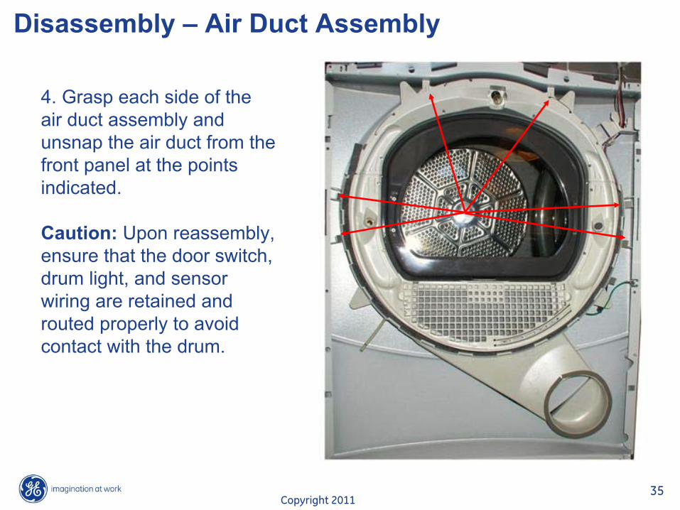
4. Grasp each side of the air duct assembly and unsnap the air duct from the front panel at the points indicated.
Caution: Upon reassembly, ensure that the door switch, drum light, and sensor wiring are retained and routed properly to avoid contact with the drum.

Copyright 201136
Disassembly – Drum Slides
Supp
ort S
lide
Supp
ort S
lide
Gui
de S
lide
Gui
de S
lide
The drum slide assembly is located on the back side of the front
panel and utilizes 4 drum slides. Two white outer slides are used as guides, and 2 dark color center (top) slides are used to support the weight of the drum. When replacing the slides, the dark-colored support slides must be used to replace the top support slides. Guide slides may also be replaced with support slides.Caution: Do not replace the center (top) support slides with the white guide slides. Damage to the dryer will result.
Copyright 201137
Disassembly – Drum Slides
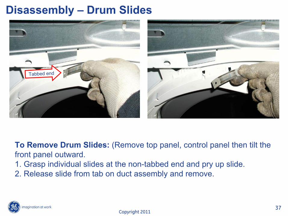
To Remove Drum Slides: (Remove top panel, control panel then tilt thefront panel outward.1. Grasp individual slides at the non-tabbed end and pry up slide.2. Release slide from tab on duct assembly and remove.
Tabbed end
Copyright 201138
Disassembly – Steam Nozzle
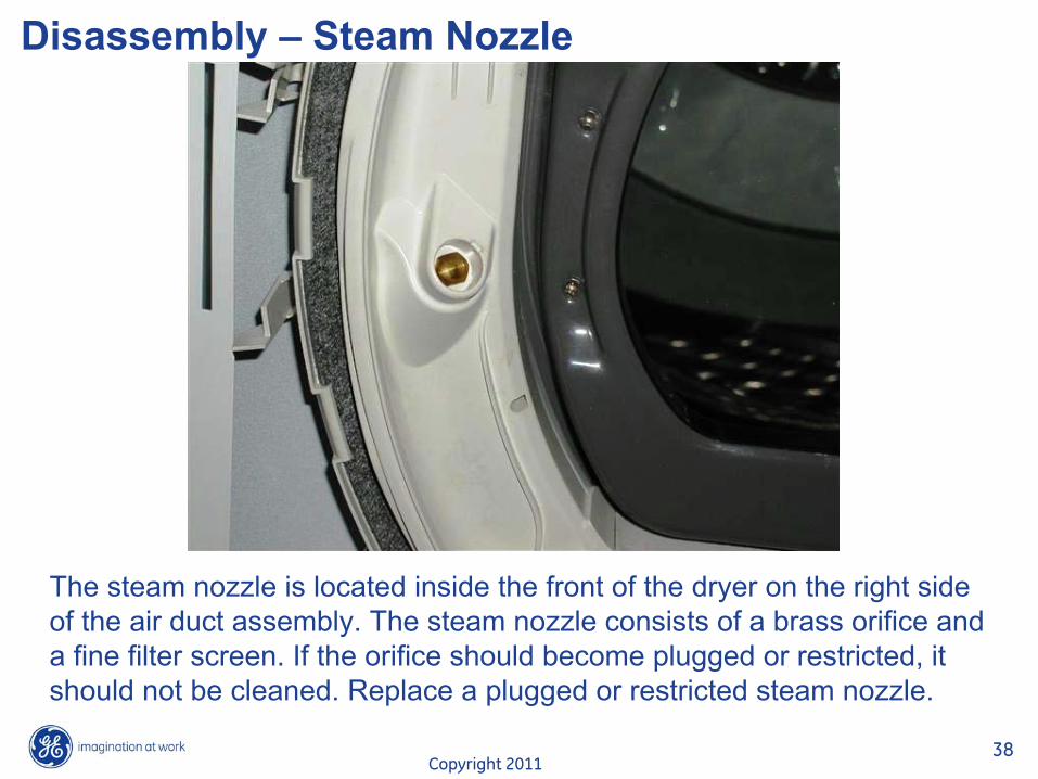
The steam nozzle is located inside the front of the dryer on the
right side of the air duct assembly. The steam nozzle consists of a brass orifice and a fine filter screen. If the orifice should become plugged or restricted, it should not be cleaned. Replace a plugged or restricted steam nozzle.
Copyright 201139
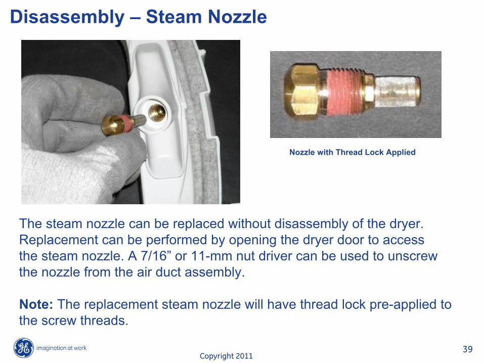
Disassembly – Steam Nozzle
Nozzle with Thread Lock Applied
The steam nozzle can be replaced without disassembly of the dryer. Replacement can be performed by opening the dryer door to accessthe steam nozzle. A 7/16”
or 11-mm nut driver can be used to unscrew the nozzle from the air duct assembly.
Note: The replacement steam nozzle will have thread lock pre-applied to the screw threads.
Copyright 201140
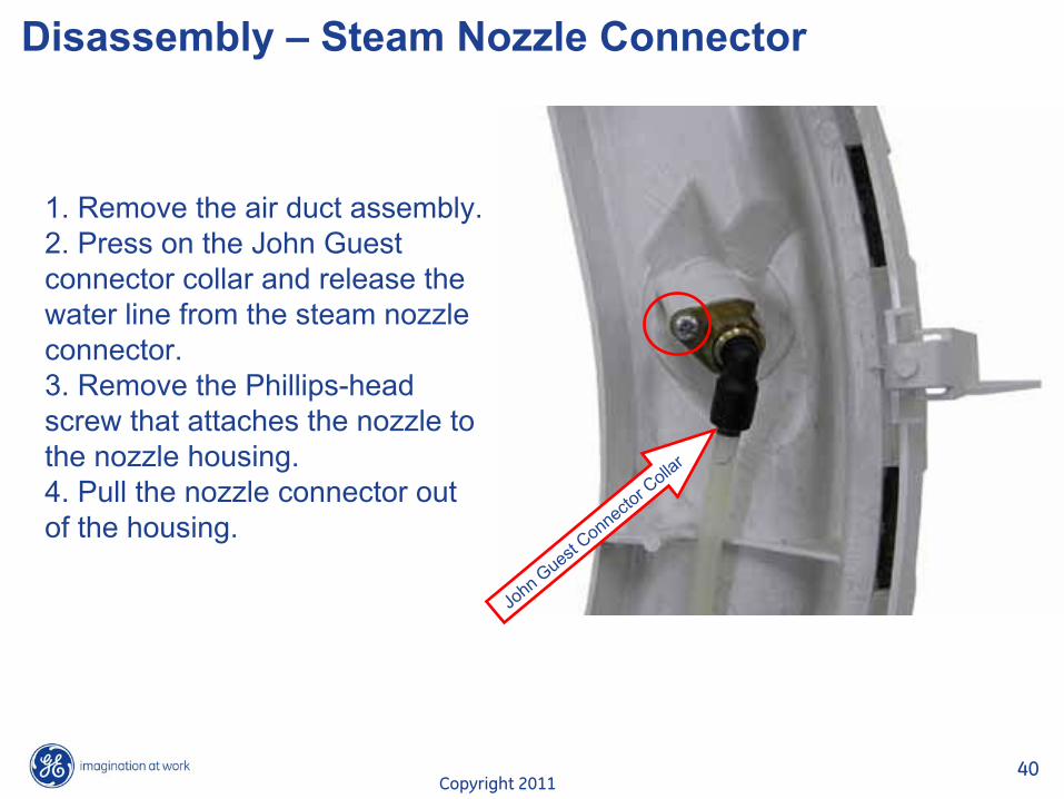
Disassembly – Steam Nozzle Connector
1. Remove the air duct assembly. 2. Press on the John Guest connector collar and release the water line from the steam nozzleconnector.3. Remove the Phillips-head screw that attaches the nozzle to the nozzle housing.4. Pull the nozzle connector out of the housing.
John G
uest Connecto
r Collar
Copyright 201141
Disassembly – Door Switch
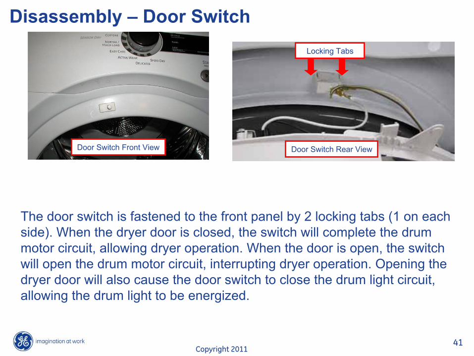
Door Switch Front View Door Switch Rear View
Locking Tabs
The door switch is fastened to the front panel by 2 locking tabs
(1 on each side). When the dryer door is closed, the switch will complete the drum motor circuit, allowing dryer operation. When the door is open, the switch will open the drum motor circuit, interrupting dryer operation. Opening the dryer door will also cause the door switch to close the drum light circuit, allowing the drum light to be energized.
Copyright 201142
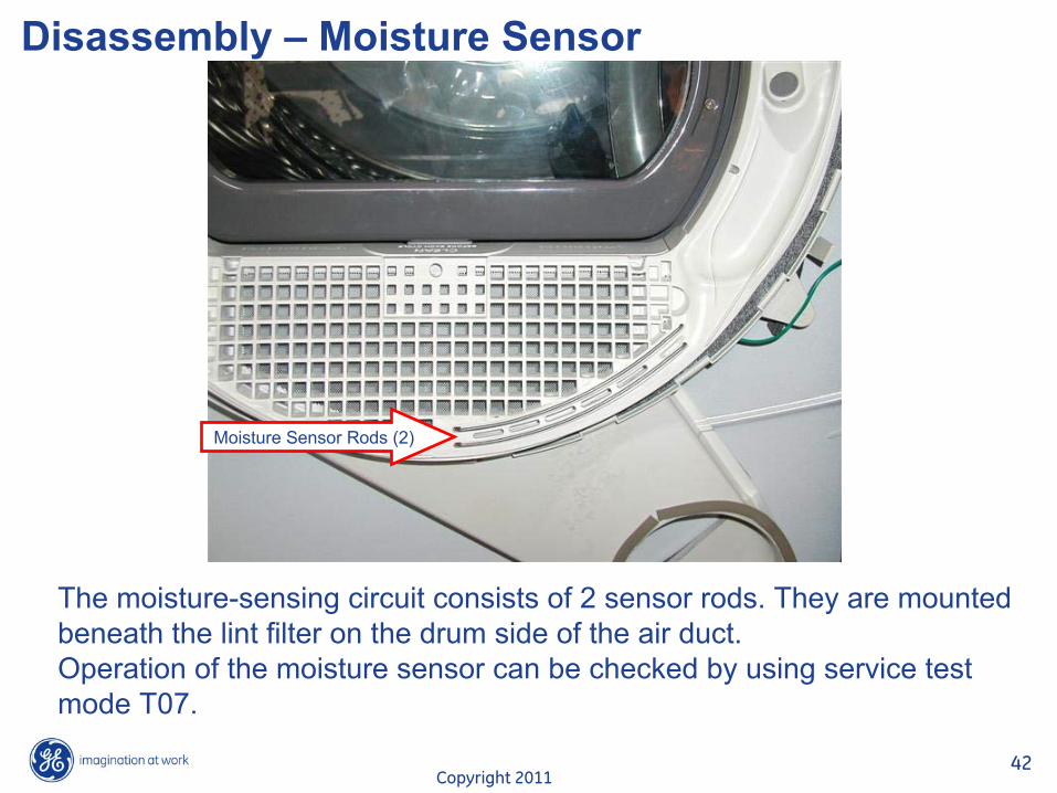
Disassembly – Moisture Sensor
The moisture-sensing circuit consists of 2 sensor rods. They are mounted beneath the lint filter on the drum side of the air duct.Operation of the moisture sensor can be checked by using service
test mode T07.
Moisture Sensor Rods (2)

Copyright 201143
Disassembly – Moisture Sensor
The dryer will signal when the clothes are at 17% moisture level
if equipped with a damp signal that has been selected.Approximate values for dryness level:Damp = 17%Less dry = 12%Dry = 2-6%More dry = <2%
Plug connecting sensorrods to J7 on control
board.

Copyright 201144
Disassembly – Moisture SensorThe sensor rods are connected to the main control board. The rods are spaced approximately ½-in. apart, which creates an open circuit to the control.
The control board utilizes a low-
voltage capacitor that charges to approximately 5 VDC when the circuit is open and discharges to less than 1 VDC when the circuit is shorted.
When wet clothes tumble across the two rods, the clothes create a very low resistance between the rods, which discharges the capacitor.As the clothes become dry, their resistance value increases and
the charge across the capacitor builds to approximately 5 VDC.

Copyright 201145
Drive Belt
The drive belt (Part #WE12M29) is a 4-rib belt and extends from under the motor pulley, over the top of the idler pulley, and around the perimeterof the dryer drum. (See belt diagram.) Belt tension is maintained by the idler pulley and driven by a pulley attached to the motor shaft.
Idler Pulley
Idler Arm
Pulley shownin locked position
Copyright 201146
Drive Belt
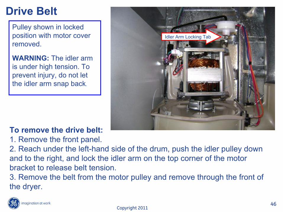
To remove the drive belt:1. Remove the front panel. 2. Reach under the left-hand side of the drum, push the idler pulley down and to the right, and lock the idler arm on the top corner of the motor bracket to release belt tension.3. Remove the belt from the motor pulley and remove through the front of the dryer.
Pulley shown in locked position with motor coverremoved.
WARNING: The idler arm is under high tension. Toprevent injury, do not let the idler arm snap back.
Idler Arm Locking Tab
Copyright 201147
Installing the Drive Belt
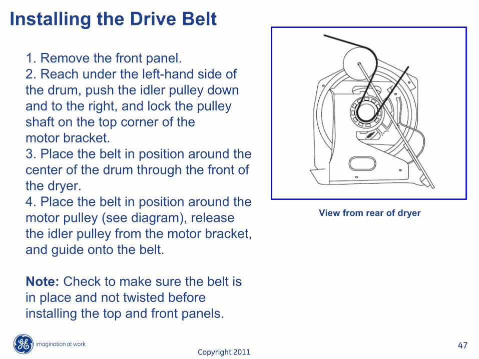
1. Remove the front panel. 2. Reach under the left-hand side of the drum, push the idler pulley down and to the right, and lock the pulley shaft on the top corner of themotor bracket. 3. Place the belt in position around the center of the drum through the front of the dryer.4. Place the belt in position around the motor pulley (see diagram), release the idler pulley from the motor bracket, and guide onto the belt.
Note: Check to make sure the belt is in place and not twisted before installing the top and front panels.
View from rear of dryer

Copyright 201148
Belt Switch (Idler Switch)
A belt switch, activated by the idler arm, is fastened to the motor bracket by 2 screws. Should the drive belt break, the belt switch will open
the drive motor circuit, interrupting dryer operation.
Note: The drum lamp will operate with an open belt switch.
Copyright 201149
Belt Switch
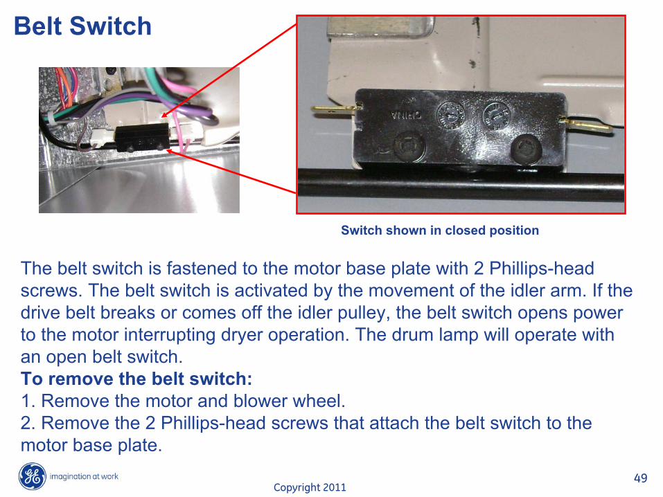
The belt switch is fastened to the motor base plate with 2 Phillips-head screws. The belt switch is activated by the movement of the idler arm. If thedrive belt breaks or comes off the idler pulley, the belt switch
opens power to the motor interrupting dryer operation. The drum lamp will operate with an open belt switch.To remove the belt switch:1. Remove the motor and blower wheel. 2. Remove the 2 Phillips-head screws that attach the belt switch to the motor base plate.
Switch shown in closed position
Copyright 201150
Drum
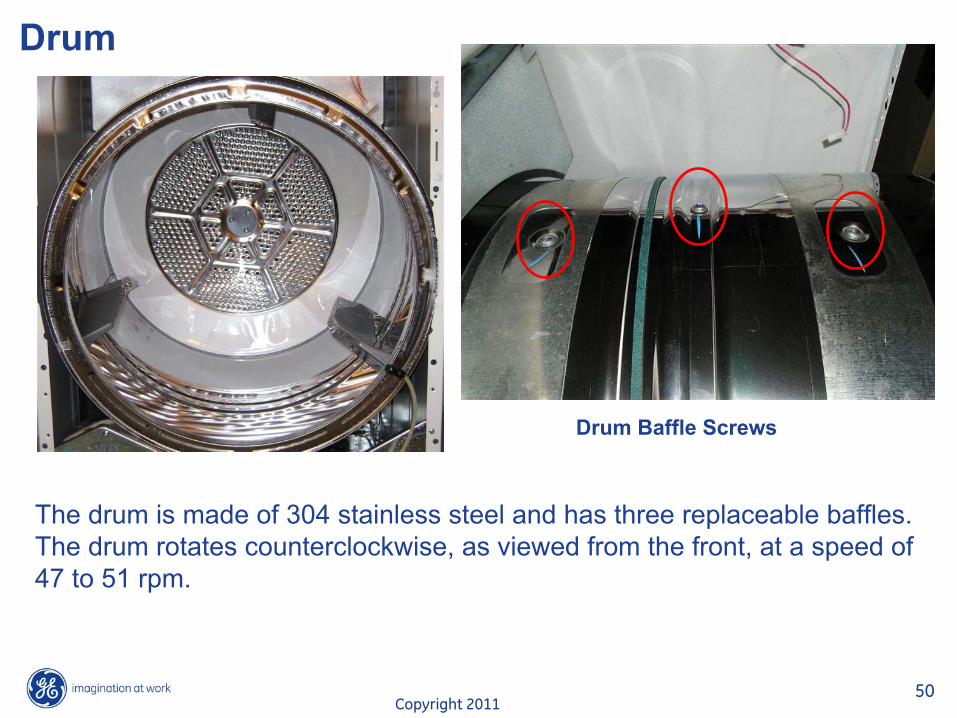
The drum is made of 304 stainless steel and has three replaceable baffles. The drum rotates counterclockwise, as viewed from the front, at a speed of 47 to 51 rpm.
Drum Baffle Screws

Copyright 201151
Drum
To remove the drum:1. Remove the drive belt from the motor. 2. Using the belt as a handle, pull the drum forward and guide out of the cabinet.
Copyright 201152
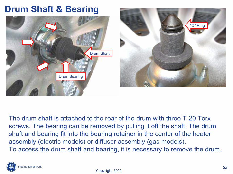
Drum Shaft & Bearing
The drum shaft is attached to the rear of the drum with three T-20 Torx
screws. The bearing can be removed by pulling it off the shaft. The drum shaft and bearing fit into the bearing retainer in the center of
the heater assembly (electric models) or diffuser assembly (gas models).To access the drum shaft and bearing, it is necessary to remove the drum.
Drum Shaft
Drum Bearing
“O”
Ring
Copyright 201153
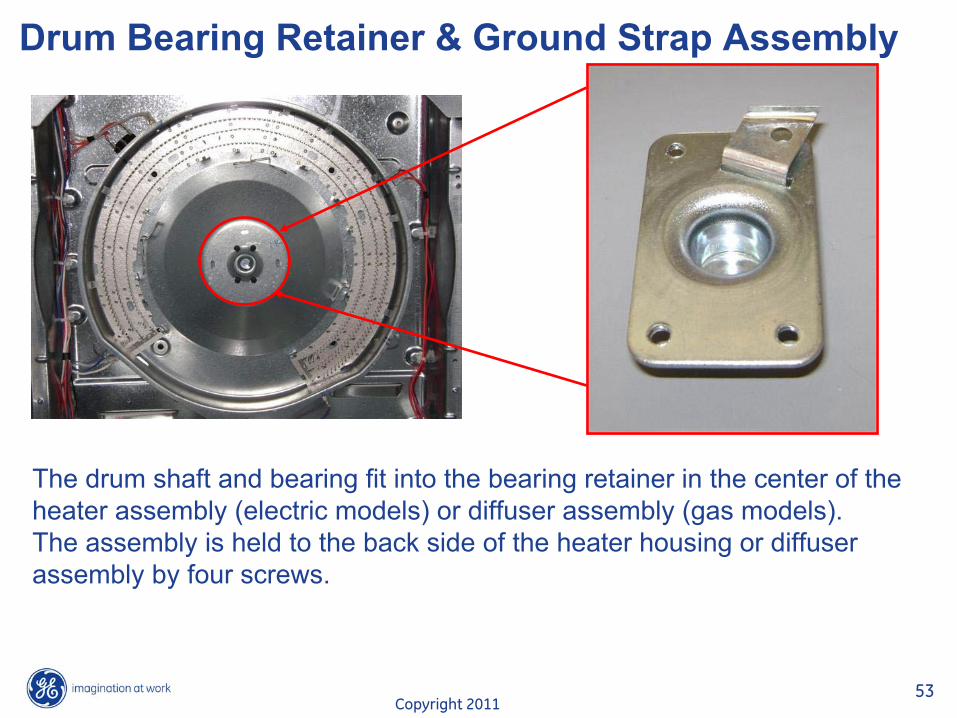
Drum Bearing Retainer & Ground Strap Assembly
The drum shaft and bearing fit into the bearing retainer in the center of the heater assembly (electric models) or diffuser assembly (gas models).The assembly is held to the back side of the heater housing or diffuser assembly by four screws.
Copyright 201154
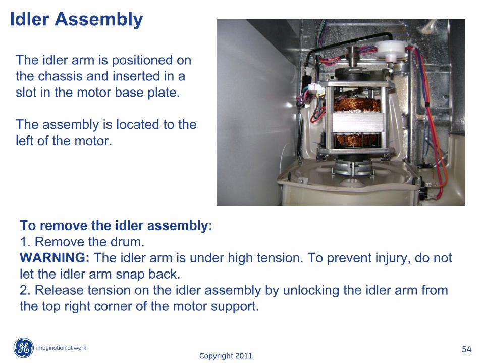
Idler Assembly
The idler arm is positioned on the chassis and inserted in a slot in the motor base plate.
The assembly is located to the left of the motor.
To remove the idler assembly:1. Remove the drum. WARNING: The idler arm is under high tension. To prevent injury, do not let the idler arm snap back.2. Release tension on the idler assembly by unlocking the idler arm from the top right corner of the motor support.

Copyright 201155
Idler Assembly
3. Remove the idler arm from the slot in the motor base plate.4. Remove the idler assembly from the dryer.
Slot in Motor Base Plate

Copyright 201156
Water Valve
The valve has an approximate resistance value of 406 �.Operation of the water inlet valve can be checked by using service test mode T07.
The water inlet valve is located inside the cabinet at the bottom right hand corner. The water valve is enclosed under a metal cover. The cover is attached to the dryer with a Phillips-
head screw and a tab located at the bottom.
Water Valve / Cover

Copyright 201157
Water Valve
To replace the inlet water valve:1. Remove the drum. 2. Remove the 2 Phillips-head screws that hold the cover to the cabinet and remove the cover by lifting up and out.
Copyright 201158
Water Valve
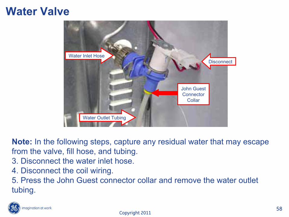
Note: In the following steps, capture any residual water that may escape from the valve, fill hose, and tubing.3. Disconnect the water inlet hose.4. Disconnect the coil wiring.5. Press the John Guest connector collar and remove the water outlet tubing.
Water Inlet HoseDisconnect
Water Outlet Tubing
John GuestConnector
Collar
Copyright 201159
Motor & Blower Wheel
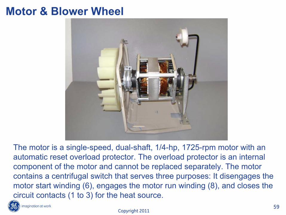
The motor is a single-speed, dual-shaft, 1/4-hp, 1725-rpm motor with an automatic reset overload protector. The overload protector is an
internalcomponent of the motor and cannot be replaced separately. The motor contains a centrifugal switch that serves three purposes: It disengages the motor start winding (6), engages the motor run winding (8), and closes the circuit contacts (1 to 3) for the heat source.
Copyright 201160
Motor & Blower Wheel
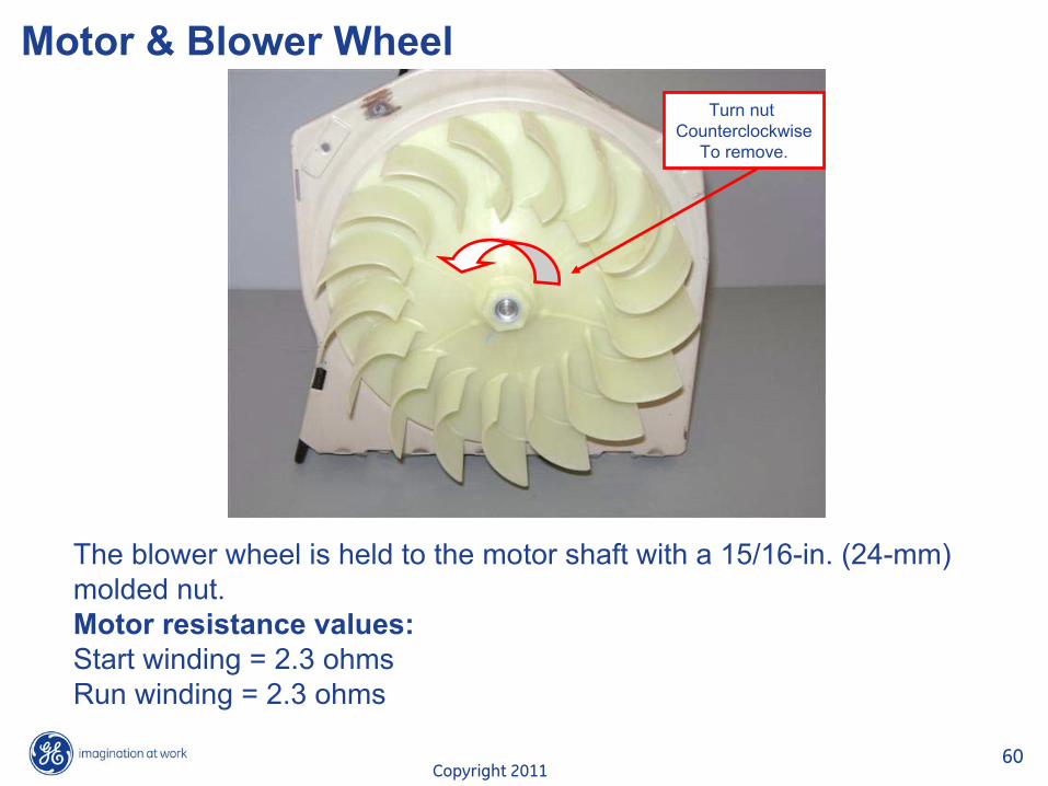
The blower wheel is held to the motor shaft with a 15/16-in. (24-mm) molded nut.Motor resistance values:Start winding = 2.3 ohmsRun winding = 2.3 ohms
Turn nut Counterclockwise
To remove.
Copyright 201161
Motor & Blower Wheel
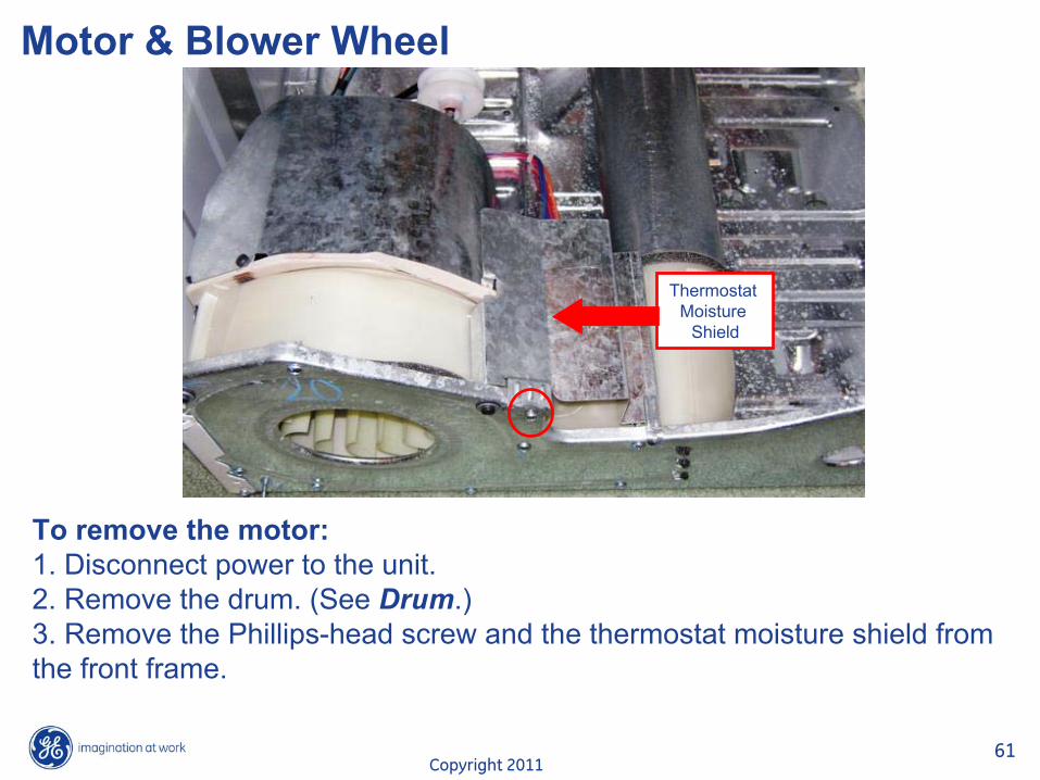
To remove the motor:1. Disconnect power to the unit.2. Remove the drum. (See Drum.)3. Remove the Phillips-head screw and the thermostat moisture shield from the front frame.
Thermostat Moisture
Shield
Copyright 201162
Motor & Blower Wheel
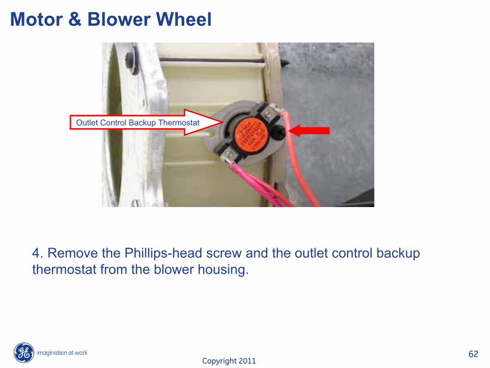
4. Remove the Phillips-head screw and the outlet control backup thermostat from the blower housing.
Outlet Control Backup Thermostat
Copyright 201163
Motor & Blower Wheel
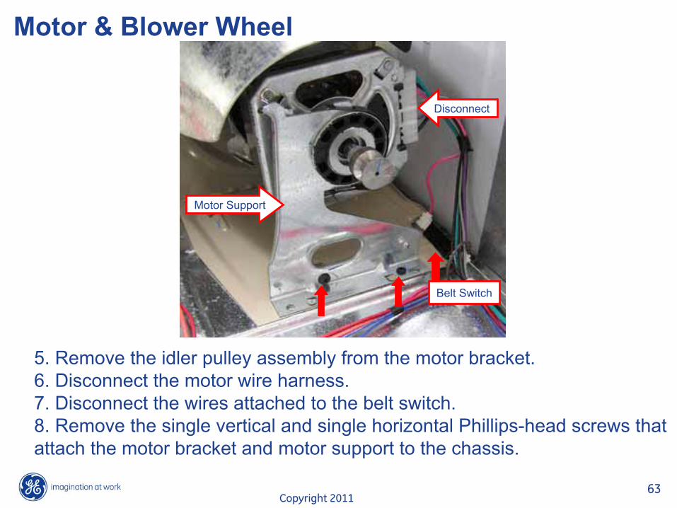
5. Remove the idler pulley assembly from the motor bracket. 6. Disconnect the motor wire harness.7. Disconnect the wires attached to the belt switch.8. Remove the single vertical and single horizontal Phillips-head screws that attach the motor bracket and motor support to the chassis.
Motor Support
Belt Switch
Disconnect
Copyright 201164
Motor & Blower Wheel
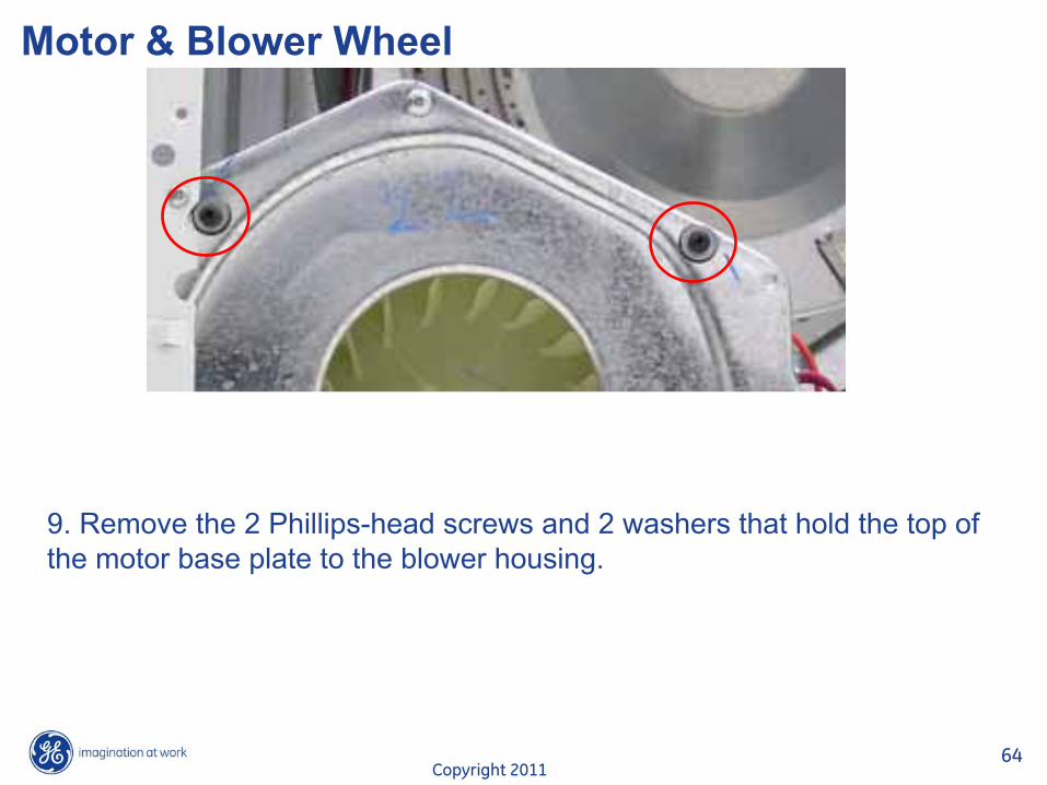
9. Remove the 2 Phillips-head screws and 2 washers that hold the top of the motor base plate to the blower housing.
Copyright 201165
Motor & Blower Wheel
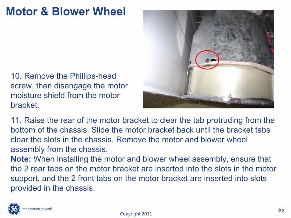
10. Remove the Phillips-head screw, then disengage the motor moisture shield from the motor bracket.
11. Raise the rear of the motor bracket to clear the tab protruding from the bottom of the chassis. Slide the motor bracket back until the bracket tabs clear the slots in the chassis. Remove the motor and blower wheel assembly from the chassis.Note: When installing the motor and blower wheel assembly, ensure that
the 2 rear tabs on the motor bracket are inserted into the slots
in the motorsupport, and the 2 front tabs on the motor bracket are inserted into slots provided in the chassis.

Copyright 201166
Motor & Blower Wheel
12. Hold the motor shaft from turning and use a 15/16-in. (24-mm) socket to remove the blower wheel from the motor shaft.
Motor S
haft
15/1
6-in.
Mold
ed N
ut

Copyright 201167
Motor & Blower Wheel
NOTES:•
When installing the motor to the motor bracket, install the motor with the motor harness terminals at the 9:30 o'clock position.•
After installing the motor, ensure both moisture shields are properly installed.
13. Compress and remove the rear motor strap from the motor support.
14. Loosen the two 1/4-in. hex-head screws on the front motor strap.
15. Lift and remove the motor from the motor bracket.
Front Motor StrapRear Motor Strap

Copyright 201168
Blower Housing
The blower housing is attached to the dryer with 7 screws and 3 tabs.To remove the blower housing:1. Remove the motor and blower wheel. 2. Remove the single Phillips-head screw located inside the outlet of the exhaust pipe. Remove the exhaust tube from the blower housing.

Copyright 201169
Blower Housing
3. Remove the 7 Phillips-head screws that attach the blower housing to the base plate.4. Slide the blower housing to the right.Note: When reinstalling the blower housing, ensure the 3 tabs are inserted into the front base plate.
Tabs

Copyright 201170
Heater Assembly
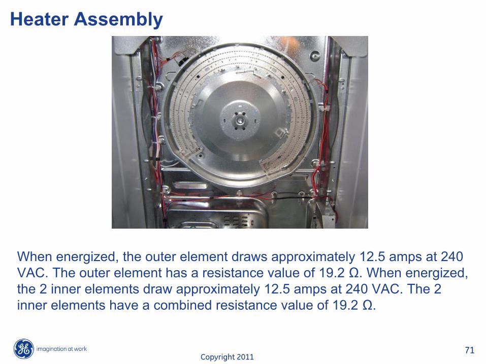
The heater assembly is located behind the drum. It consists of inner and outer open-wire elements, each formed in a zigzag pattern fastened to a single housing. The inner element consists of 2 elements wired in parallel with each. The inner element and the outer element are controlled by separate relays on the control board.
Copyright 201171
Heater Assembly
When energized, the outer element draws approximately 12.5 amps at 240 VAC. The outer element has a resistance value of 19.2 �. When energized, the 2 inner elements draw approximately 12.5 amps at 240 VAC. The 2 inner elements have a combined resistance value of 19.2 �.
Copyright 201172
Heater Assembly
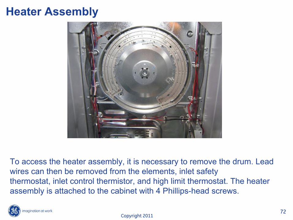
To access the heater assembly, it is necessary to remove the drum. Lead wires can then be removed from the elements, inlet safetythermostat, inlet control thermistor, and high limit thermostat. The heater assembly is attached to the cabinet with 4 Phillips-head screws.
Copyright 201173
Heater Assembly
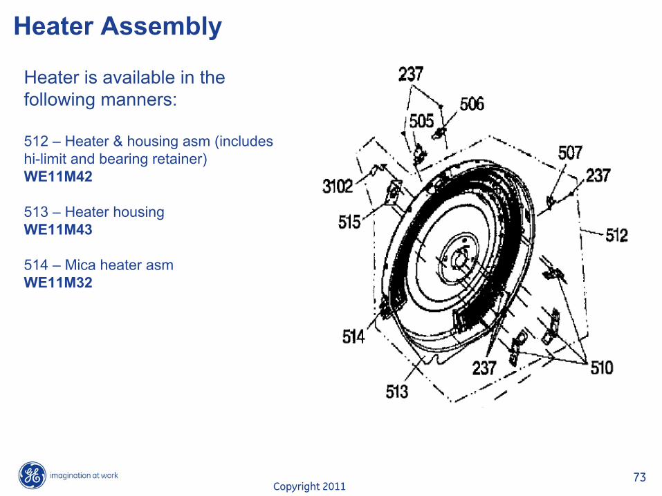
Heater is available in thefollowing manners:
512 –
Heater & housing asm
(includes hi-limit and bearing retainer)WE11M42
513 –
Heater housingWE11M43
514 –
Mica heater asmWE11M32

Copyright 201174
Heater Assembly
To Remove Mica Heater Assembly:1.
Remove leads from heater assembly.2.
Bend back single metal tab on housing holding heater in place.

Copyright 201175
Heater Assembly
3. Rotate mica assembly slightly counterclockwise to align numerous gaps on mica surface with tabs on housing.
4. Lift mica heater assembly from housing.
Tab & Gap
Tab & Gap
Copyright 201176
Burner Assembly & Conversion
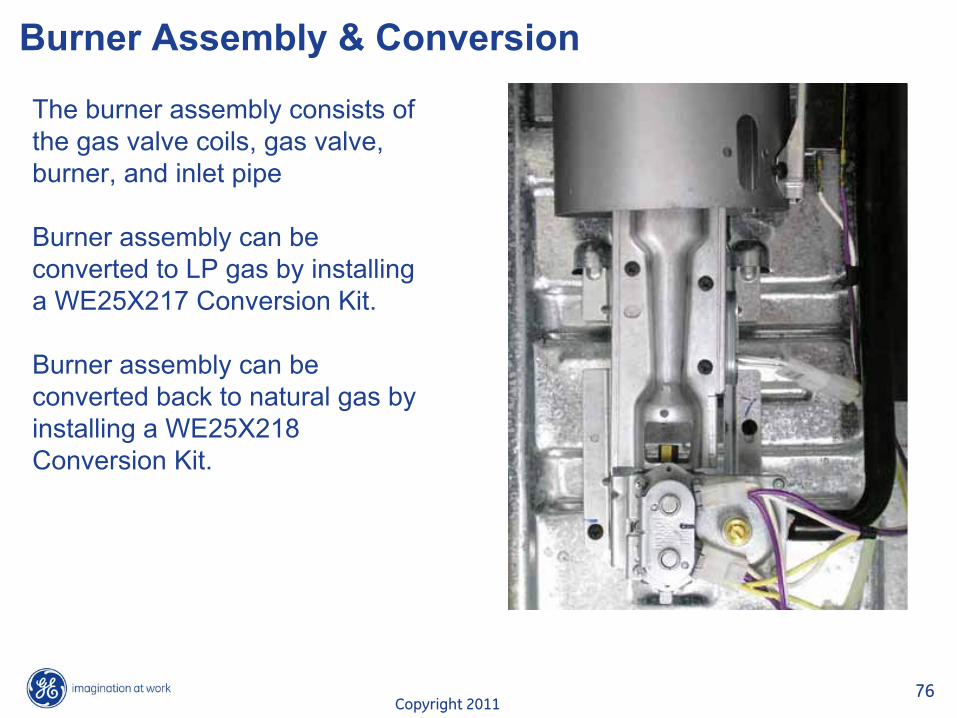
The burner assembly consists of the gas valve coils, gas valve, burner, and inlet pipe
Burner assembly can be converted to LP gas by installing a WE25X217 Conversion Kit.
Burner assembly can be converted back to natural gas by installing a WE25X218 Conversion Kit.
Copyright 201177
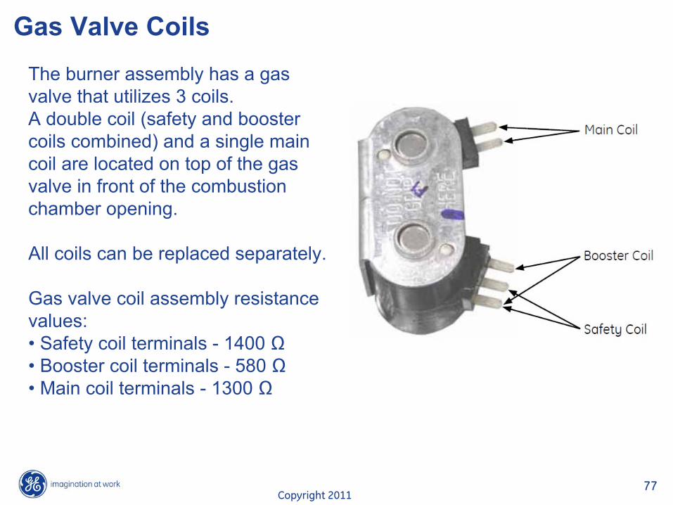
Gas Valve CoilsThe burner assembly has a gas valve that utilizes 3 coils. A double coil (safety and booster coils combined) and a single main coil are located on top of the gas valve in front of the combustion chamber opening.
All coils can be replaced separately.
Gas valve coil assembly resistance values:•
Safety coil terminals -
1400 �•
Booster coil terminals -
580 �•
Main coil terminals -
1300 �
Copyright 201178
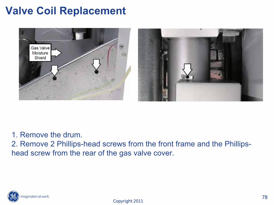
Valve Coil Replacement
1. Remove the drum. 2. Remove 2 Phillips-head screws from the front frame and the Phillips-
head screw from the rear of the gas valve cover.
Copyright 201179
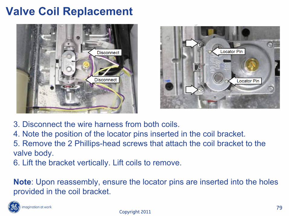
Valve Coil Replacement
3. Disconnect the wire harness from both coils.4. Note the position of the locator pins inserted in the coil bracket.5. Remove the 2 Phillips-head screws that attach the coil bracket to the valve body.6. Lift the bracket vertically. Lift coils to remove.
Note: Upon reassembly, ensure the locator pins are inserted into the
holes provided in the coil bracket.
Copyright 201180
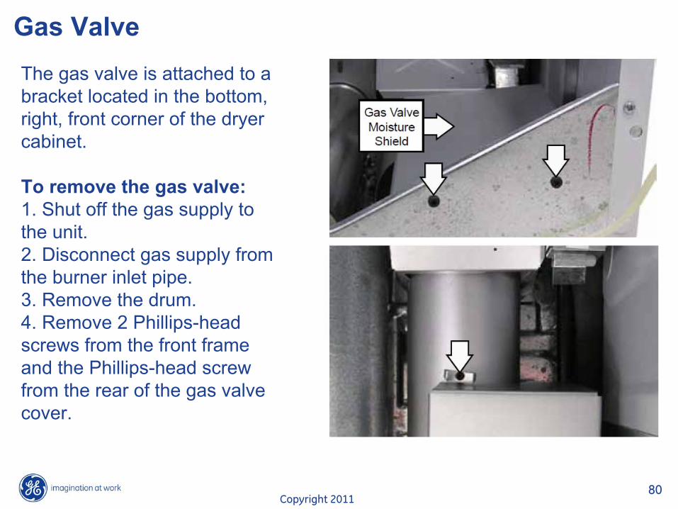
Gas Valve The gas valve is attached to a bracket located in the bottom, right, front corner of the dryer cabinet.
To remove the gas valve:1. Shut off the gas supply to the unit.2. Disconnect gas supply from the burner inlet pipe.3. Remove the drum. 4. Remove 2 Phillips-head screws from the front frame and the Phillips-head screw from the rear of the gas valve cover.
Copyright 201181
Gas Valve
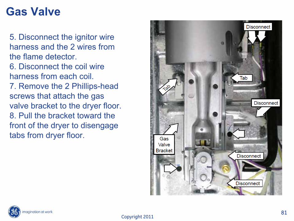
5. Disconnect the ignitor
wire harness and the 2 wires from the flame detector.6. Disconnect the coil wire harness from each coil.7. Remove the 2 Phillips-head screws that attach the gas valve bracket to the dryer floor.8. Pull the bracket toward the front of the dryer to disengage tabs from dryer floor.
Copyright 201182
Gas Valve
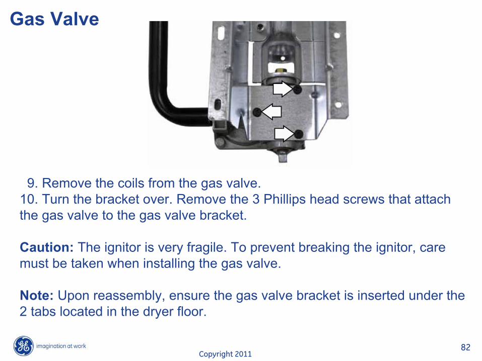
9. Remove the coils from the gas valve. 10. Turn the bracket over. Remove the 3 Phillips head screws that attach the gas valve to the gas valve bracket.
Caution: The ignitor
is very fragile. To prevent breaking the ignitor, care must be taken when installing the gas valve.
Note: Upon reassembly, ensure the gas valve bracket is inserted under the 2 tabs located in the dryer floor.
Copyright 201183
Ignitor
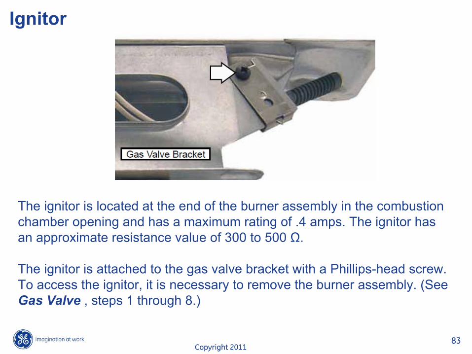
The ignitor
is located at the end of the burner assembly in the combustion chamber opening and has a maximum rating of .4 amps. The ignitor
has an approximate resistance value of 300 to 500 ȍ.
The ignitor
is attached to the gas valve bracket with a Phillips-head screw. To access the ignitor, it is necessary to remove the burner assembly. (See Gas Valve , steps 1 through 8.)
Copyright 201184
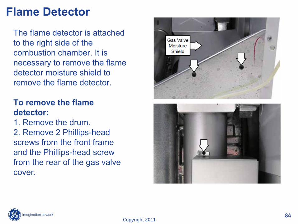
Flame DetectorThe flame detector is attached to the right side of the combustion chamber. It is necessary to remove the flame detector moisture shield to remove the flame detector.
To remove the flame detector:1. Remove the drum. 2. Remove 2 Phillips-head screws from the front frame and the Phillips-head screw from the rear of the gas valve cover.
Copyright 201185
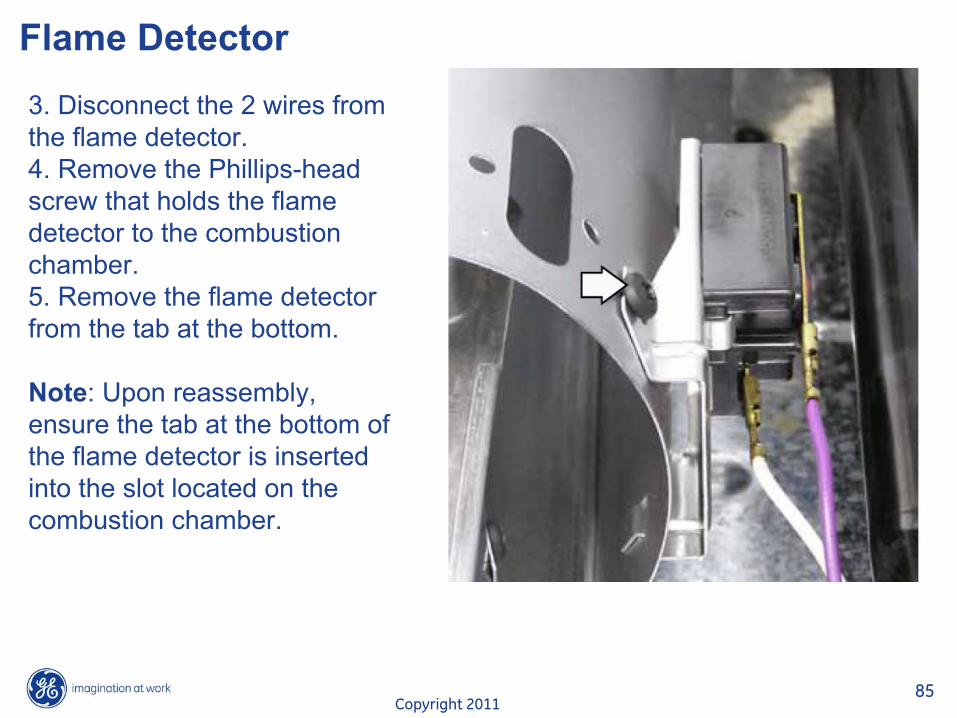
Flame Detector3. Disconnect the 2 wires from the flame detector.4. Remove the Phillips-head screw that holds the flame detector to the combustion chamber.5. Remove the flame detector from the tab at the bottom.
Note: Upon reassembly, ensure the tab at the bottom of the flame detector is inserted into the slot located on the combustion chamber.
Copyright 201186
Inlet Safety Thermostat
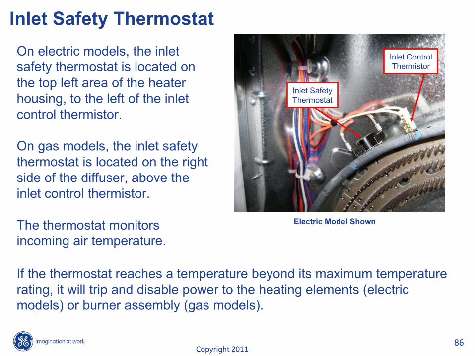
Inlet SafetyThermostat
Inlet ControlThermistor
On electric models, the inlet safety thermostat is located on the top left area of the heater housing, to the left of the inlet control thermistor.
On gas models, the inlet safety thermostat is located on the right side of the diffuser, above the inlet control thermistor.
The thermostat monitors incoming air temperature.
If the thermostat reaches a temperature beyond its maximum temperature rating, it will trip and disable power to the heating elements (electric models) or burner assembly (gas models).
Electric Model Shown
Copyright 201187
Inlet Safety Thermostat
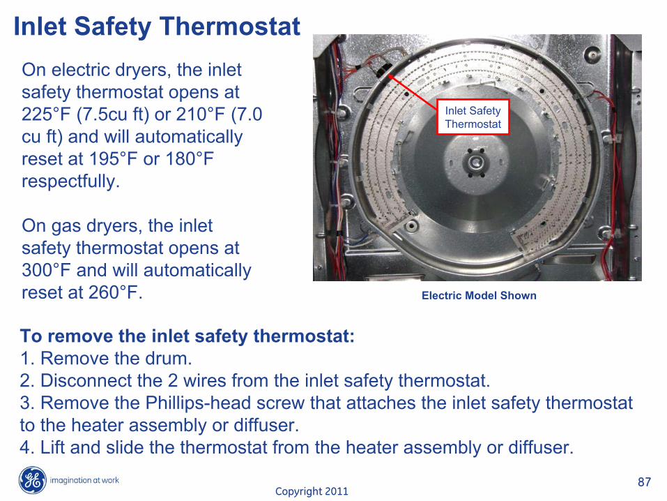
Inlet SafetyThermostat
On electric dryers, the inlet safety thermostat opens at 225°F (7.5cu ft) or 210°F (7.0 cu ft) and will automatically reset at 195°F or 180°F respectfully.
On gas dryers, the inlet safety thermostat opens at 300°F and will automatically reset at 260°F. Electric Model Shown
To remove the inlet safety thermostat:1. Remove the drum. 2. Disconnect the 2 wires from the inlet safety thermostat.3. Remove the Phillips-head screw that attaches the inlet safety thermostat to the heater assembly or diffuser.4. Lift and slide the thermostat from the heater assembly or diffuser.
Copyright 201188
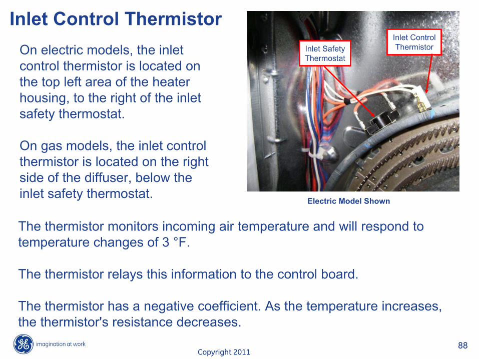
Inlet Control ThermistorInlet SafetyThermostat
Inlet ControlThermistorOn electric models, the inlet
control thermistor
is located on the top left area of the heater housing, to the right of the inlet safety thermostat.
On gas models, the inlet control thermistor
is located on the right side of the diffuser, below the inlet safety thermostat.
The thermistor
monitors incoming air temperature and will respond to temperature changes of 3 °F.
The thermistor
relays this information to the control board.
The thermistor
has a negative coefficient. As the temperature increases, the thermistor's
resistance decreases.
Electric Model Shown
Copyright 201189
Inlet Control Thermistor
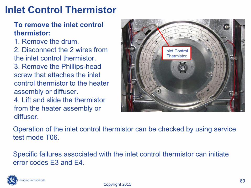
Inlet ControlThermistor
Operation of the inlet control thermistor
can be checked by using service test mode T06.
Specific failures associated with the inlet control thermistor
can initiate error codes E3 and E4.
To remove the inlet control thermistor:1. Remove the drum. 2. Disconnect the 2 wires from the inlet control thermistor.3. Remove the Phillips-head screw that attaches the inlet control thermistor
to the heaterassembly or diffuser.4. Lift and slide the thermistor
from the heater assembly or diffuser.
Copyright 201190
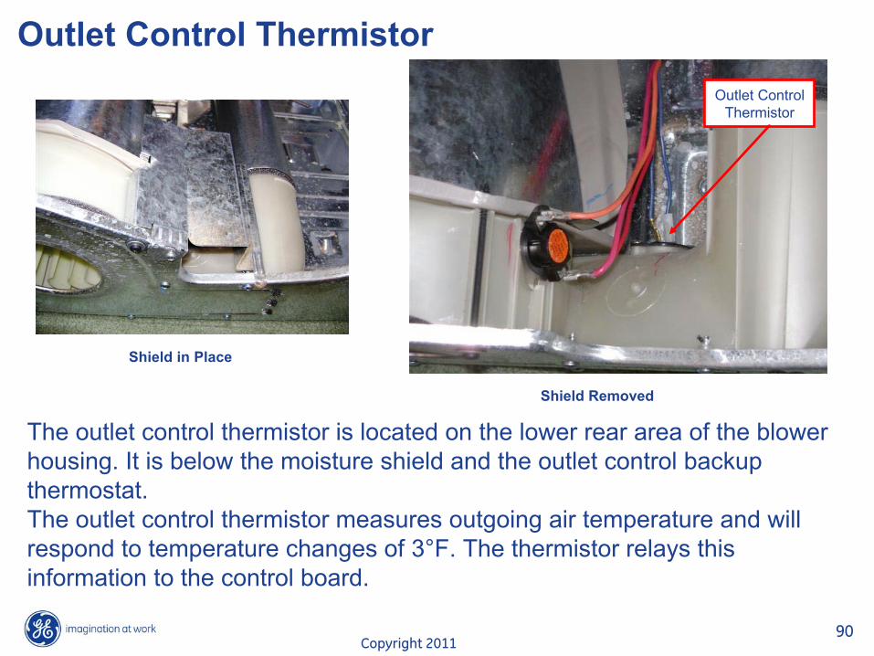
Outlet Control Thermistor
Shield in Place
Shield Removed
Outlet ControlThermistor
The outlet control thermistor
is located on the lower rear area of the blower housing. It is below the moisture shield and the outlet control backupthermostat. The outlet control thermistor
measures outgoing air temperature and will respond to temperature changes of 3°F. The thermistor
relays this information to the control board.

Copyright 201191
Outlet Control Thermistor
Operation of the outlet control thermistor
can be checked by using service test mode T05.
Specific failures associated with the outlet control thermistor
can initiate error codes E5 and E6.
To remove the outlet control thermistor:1. Remove the drum. 2. Remove the Phillips-head screw and the thermostat moisture shield from the front frame.3. Disconnect the 2 wires from the outlet control thermistor.4. Remove the 2 Phillips-head screws that attach the outlet control thermistor
to the blower housing.
Copyright 201192
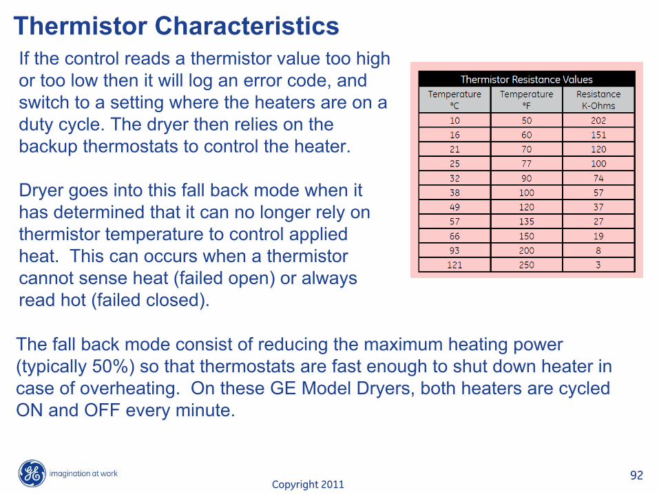
Thermistor CharacteristicsIf the control reads a thermistor
value too high or too low then it will log an error code, and switch to a setting where the heaters are on a duty cycle. The dryer then relies on the backup thermostats to control the heater.
Dryer goes into this fall back mode when it has determined that it can no longer rely on thermistor
temperature to control applied heat.
This can occurs when a thermistor
cannot sense heat (failed open) or always read hot (failed closed).
The fall back mode consist of reducing the maximum heating power
(typically 50%) so that thermostats are fast enough to shut down
heater in case of overheating.
On these GE Model Dryers, both heaters are cycled ON and OFF every minute.
Copyright 201193
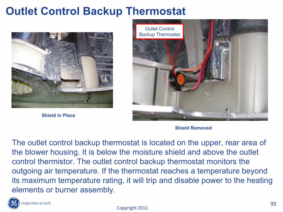
Outlet Control Backup Thermostat
Shield in Place
Shield Removed
Outlet ControlBackup Thermostat
The outlet control backup thermostat is located on the upper, rear area of the blower housing. It is below the moisture shield and above the outletcontrol thermistor. The outlet control backup thermostat monitors the outgoing air temperature. If the thermostat reaches a temperature beyond its maximum temperature rating, it will trip and disable power to the heating elements or burner assembly.
Copyright 201194
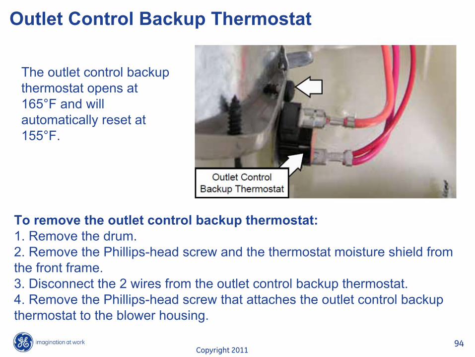
Outlet Control Backup Thermostat
The outlet control backup thermostat opens at 165°F and will automatically reset at 155°F.
To remove the outlet control backup thermostat:1. Remove the drum. 2. Remove the Phillips-head screw and the thermostat moisture shield from the front frame.3. Disconnect the 2 wires from the outlet control backup thermostat.4. Remove the Phillips-head screw that attaches the outlet control backup thermostat to the blower housing.

Copyright 201195
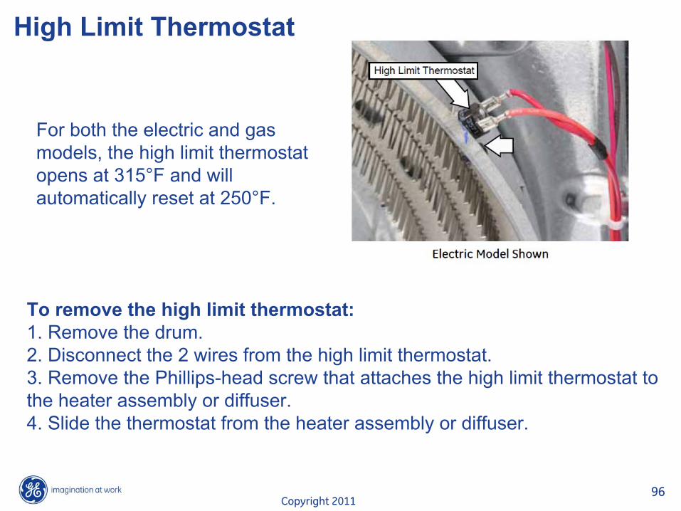
High Limit Thermostat
High LimitThermostat
On electric models, the high limit thermostat is located on the top right area of the heater housing.
On gas models, the high limit thermostat is located on the upper right side of the diffuser.
The high limit thermostat monitors incoming air temperature.
If the high limit thermostat trips it will take out the L1 circuit to the motor which, in turn, will disable the heat source.
Copyright 201196
High Limit Thermostat
For both the electric and gas models, the high limit thermostat opens at 315°F and will automatically reset at 250°F.
To remove the high limit thermostat:1. Remove the drum. 2. Disconnect the 2 wires from the high limit thermostat.3. Remove the Phillips-head screw that attaches the high limit thermostat to the heater assembly or diffuser.4. Slide the thermostat from the heater assembly or diffuser.
Copyright 201197
Service Mode TestHow to enter to service mode and navigate:From idle state, press and alternate between the “My cycle”
and “Delay Start”
buttons twice to enter service mode.
Upon entering the service mode, the Control shall be in test selection mode and display the first test number (t01). Rotating the knob counter clockwise (CCW) shall decrement the test number in the display. Rotating the knob clockwise (CW) shall increment the test numbers in the display.
Once the test number is selected, pressing [Start/Pause] shall begin the selected test.
During a test, pressing power button shall terminate that test and bring the control to the test selection mode (test number is displayed on the display).
Pressing Power key during the test selection mode shall exit the
Service mode.
Copyright 201198
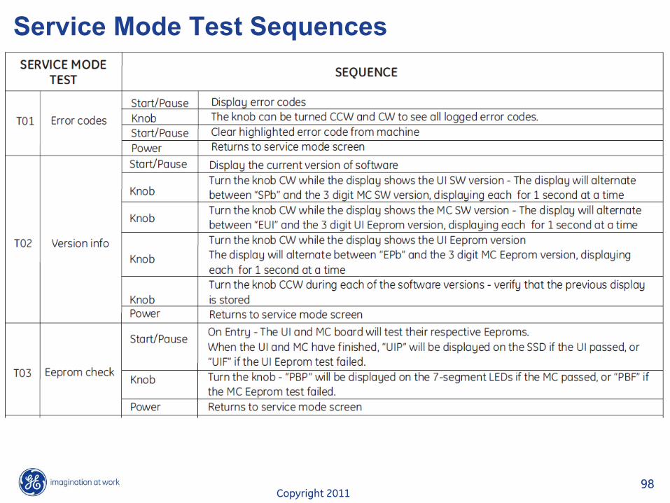
Service Mode Test Sequences

Copyright 201199
Service Mode Test Sequences
Copyright 2011100
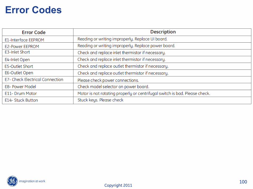
Error Codes
Copyright 2011101
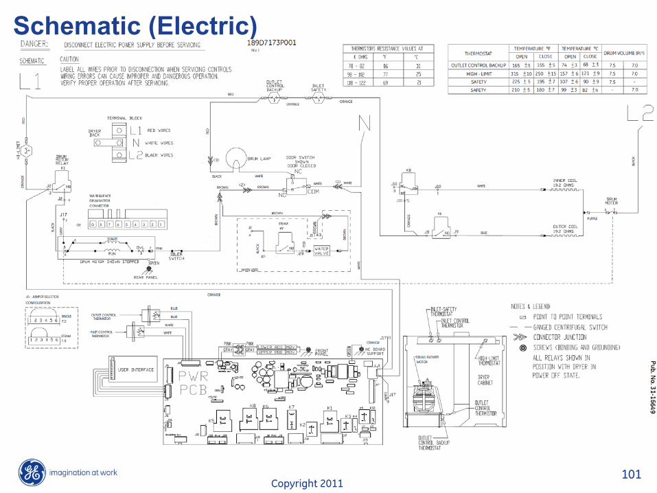
Schematic (Electric)
Copyright 2011102
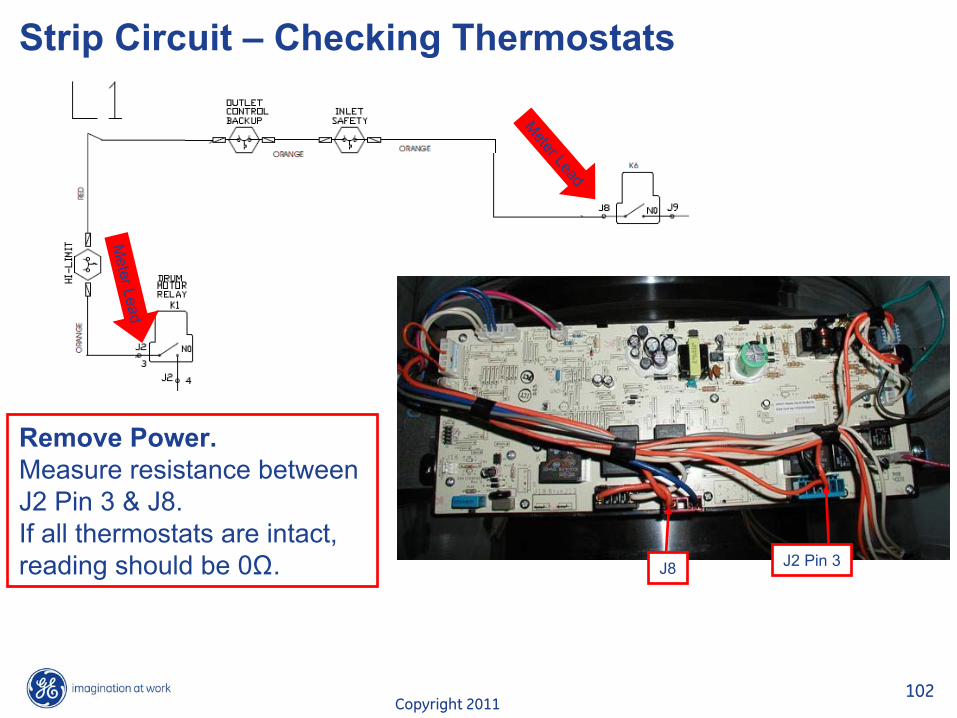
Strip Circuit – Checking Thermostats
Remove Power.Measure resistance between J2 Pin 3 & J8. If all thermostats are intact, reading should be 0ȍ.
Meter Lead
Meter Lead
J8 J2 Pin 3

Copyright 2011103
Strip Circuit – Belt SwitchRemove Power.Measure resistance between J2 Pin 4 & Plug. If belt switch & motor are intact, reading should be @ 3ȍ.
J2 Pin 4
Plug
Meter LeadMeter Lead

Copyright 2011104
Strip Circuit - Heaters
Remove Power.Measure resistance between J9 & J10. If both heaters are intact, reading should be @ 40ȍ.
Meter Lead
Meter Lead
J9J10
Copyright 2011105
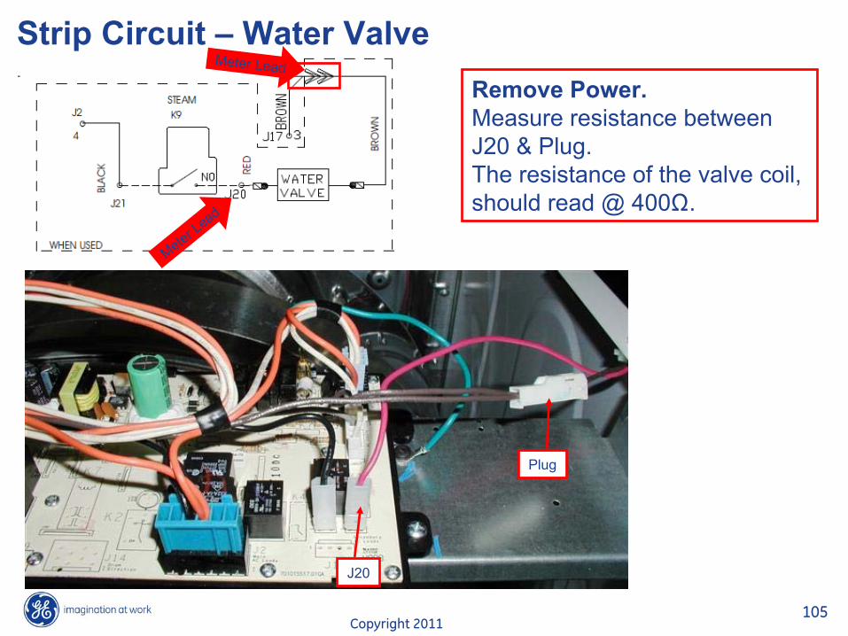
Strip Circuit – Water ValveRemove Power.Measure resistance between J20 & Plug. The resistance of the valve coil, should read @ 400ȍ.
Meter Lead
Meter Lead
J20
Plug
Copyright 2011106
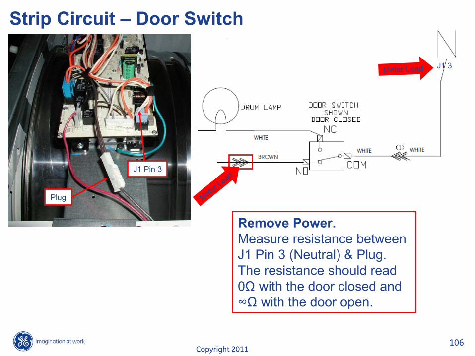
Strip Circuit – Door Switch
J1 3
Remove Power.Measure resistance between J1 Pin 3 (Neutral) & Plug. The resistance should read 0ȍ
with the door closed and�ȍ
with the door open.
Plug
J1 Pin 3
Meter Lead
Meter Lead
Copyright 2011107
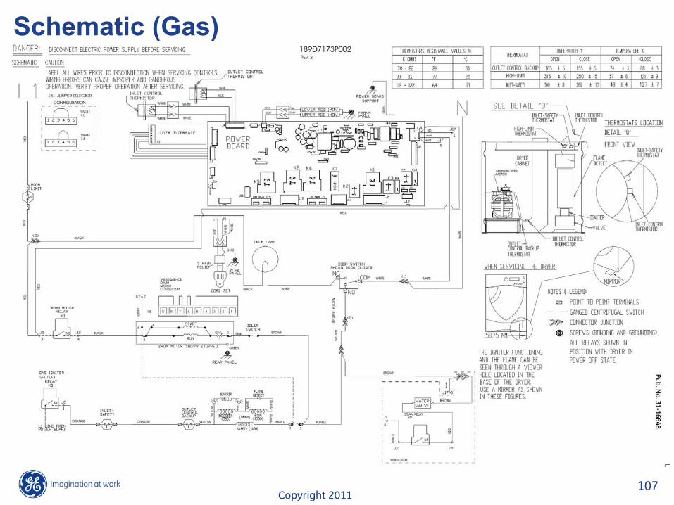
Schematic (Gas)

Copyright 2011108
Strip CircuitStrip Circuit – Water ValveRemove Power.Measure resistance between J20 & Plug. The resistance of the valve coil, should read @ 400ȍ.
Meter Lead
Meter Lead
J20
Plug

Copyright 2011109
Strip CircuitStrip Circuit – Door Switch
J1 3
Remove Power.Measure resistance between J1 Pin 3 (Neutral) & Plug. The resistance should read 0ȍ
with the door closed and�ȍ
with the door open.
Plug
J1 Pin 3
Meter Lead
Meter Lead

Copyright 2011110
Strip CircuitStrip Circuit – Belt SwitchRemove Power.Measure resistance between J2 Pin 4 & Plug. If belt switch is intact, reading should be @ 3ȍ.
J2 Pin 4
Plug
Meter LeadMeter Lead

Copyright 2011111
END OF PRESENTATION


![ge · visiting ge.com or bg calling 800.GE.CARES (800.432.2737). [] Properlyground dryer to conform with all governing codesand ordinances. Followdetails in Installation Instructions](https://img.pdfslide.us/doc/110x75/5fff235a919892545a6bbfbb/ge-visiting-gecom-or-bg-calling-800gecares-8004322737-properlyground.jpg)