Embed Size (px)
DESCRIPTION
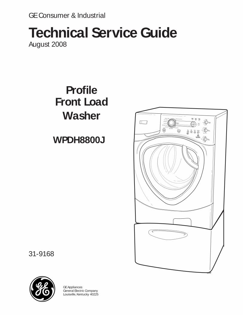
GE AppliancesGeneral Electric CompanyLouisville, Kentucky 4022531-9168ProfileFront LoadWasher WPDH8800J
Citation preview
GE AppliancesGeneral Electric CompanyLouisville, Kentucky 40225
31-9168
Profi leFront Load
Washer
WPDH8800J
Technical Service GuideAugust 2008
GE Consumer & Industrial
ELICATESD
OWERPPEEDS
ASHABLEW
ASHW
OOLW
ANDWASHH
INSER PINS&RAIND PINS&
CTIVEA EARW
RINKLE REEW FHITES /W EAVY UTYH D
LOCK
ANITARYS
ARMW
OTH
ACKB
OLDCAPT
ORMAL
ASHWEMPTPECIALITYS
YCLESC
EVELLOILS
XTRAE IGHTL
IGHTL
XTRAE
XTRAE
XTRAEINSER MARTS
ISPENSERD
YMYCLEC REP
ASHW
EAVYH
EAVYH
NSTART
PEEDSPINS
OLDC
IGHH
IGHH
EDIUMM
OWL
ON PINS

– 2 –
IMPORTANT SAFETY NOTICE
The information in this service guide is intended for use byindividuals possessing adequate backgrounds of electrical,electronic, and mechanical experience. Any attempt to repair amajor ap pli ance may result in personal injury and property damage. The man u fac tur er or seller cannot be responsible for the in ter pre ta tion of this in for ma tion, nor can it assume any liability in connection with its use.
WARNING
To avoid personal injury, disconnect power before servicing this prod uct . If electrical power is required for diagnosis or test purposes, disconnect the power immediately after performing the necessary checks.
RECONNECT ALL GROUNDING DEVICES
If grounding wires, screws, straps, clips, nuts, or washers used to complete a path to ground are removed for service, they must be returned to their original position and properly fastened.
GE Consumer & IndustrialTechnical Service Guide
Copyright © 2008All rights reserved. This service guide may not be reproduced in whole or in partin any form without written permission from the General Electric Company.

– 3 –
Table of Contents
Basic Wash Cycle .............................................................................................................................................................16
Belt ...........................................................................................................................................................................................39
Circuit Board Connections ............................................................................................................................................20
Component Locator Views ...........................................................................................................................................18
Control Board ......................................................................................................................................................................24
Control Features ................................................................................................................................................................ 6
Control Panel .....................................................................................................................................................................23
Dampers ...............................................................................................................................................................................46
Dispenser Assembly ........................................................................................................................................................28
Dispenser Motor ................................................................................................................................................................30
Door .......................................................................................................................................................................................42
Door Hinge ...........................................................................................................................................................................44
Door Lock..............................................................................................................................................................................26
Door Strike ............................................................................................................................................................................27
Error Codes ..........................................................................................................................................................................56
Front Panel ...........................................................................................................................................................................27
Heater Assembly ...............................................................................................................................................................36
Introduction ......................................................................................................................................................................... 5
Inverter ..................................................................................................................................................................................38
Line Filter...............................................................................................................................................................................25
Motor Assembly ................................................................................................................................................................40
Nomenclature .................................................................................................................................................................... 4
Operation Overview .........................................................................................................................................................16
Outer Tub Assembly and Suspension ....................................................................................................................50
Power Board Assembly ..................................................................................................................................................31
Pump ......................................................................................................................................................................................34
Schematic.............................................................................................................................................................................59
Service Panel.......................................................................................................................................................................22
Service Test Mode .............................................................................................................................................................52
Top Panel ..............................................................................................................................................................................22
Tub Gasket (Boot) ..............................................................................................................................................................45
Using the Washer .............................................................................................................................................................12
VFD (Vacuum Fluorescent Display) .........................................................................................................................25
Warranty .............................................................................................................................................................................60
Wash Basket .......................................................................................................................................................................47
Wash Basket Pulley .........................................................................................................................................................40
Washer Components ......................................................................................................................................................22
Water Level Control .........................................................................................................................................................32
Water Valve .........................................................................................................................................................................33

– 4 –
Model Number
Nomenclature
The nomenclature tag is lo cat ed in two places: behind the door, and near the bottom front corner on the right side of the cabinet.
Note: The technical sheet is located behind the service panel on the right side.
Nomenclature
Capacity/Confi gurationD = SmartDispense Ready
W P D H 8 8 0 0 J 0 W W
Feature PackageP = Profi le
PlatformH = Horizontal
Engineering Revision
ColorWW = WhiteMV = Vermillion RedMG = Champagne
Model YearF - 2005G - 2006H - 2007J - 2008K - 2009
Voltage0 = US Voltage
Control Features
The letter des ig nat ing the year re peats every 12 years.
Example:
T - 1974 T - 1986 T - 1998
Serial Number
The fi rst two characters of the serial number identify the month and year of manufacture. Example: AR123456S = January, 2008
A - JAN 2008 - RD - FEB 2007 - MF - MAR 2006 - LG - APR 2005 - HH - MAY 2004 - GL - JUN 2003 - FM - JUL 2002 - DR - AUG 2001 - AS - SEP 2000 - ZT - OCT 1999 - VV - NOV 1998 - TZ - DEC 1997 - S
BrandW = General Electric

– 5 –
Introduction
The new Profi le Front Load Washer has the following features:
Energy Star Qualifi cation assures less energy waste and lower utility bills.•
10 wash cycles include a variety of fabric-specifi c settings, from Extra-Heavy Cottons to Easy-Care • Colors.
My Cycle selection saves a favorite cycle for future use. •
Dispenser adds diluted detergent, bleach, and fabric softener at the correct time during the wash or rinse • cycles.
A nozzle sprays water on the inner door glass to reduce detergent and mineral buildup.•
End-Of-Cycle Signal alerts user when the cycle is fi nished, saving time between loads. Signal volume can • be adjusted.
Overfl ow protection activates the drain pump whenever water reaches overfl ow level.•
A built-in Service test mode can operate specifi c washer components and record any associated error • codes. This diagnostic feature can be accessed on the control panel's VFD ( Vacuum Fluorescent Display).
Two-piece plastic outer tub is formed from tough, lightweight polypropylene.•
The wash tub is constructed of durable stainless steel. •
Two suspension springs and four dampers provide maximum off-balance load protection with minimal • vibration transfer to the fl oor.
Intricate door lock keeps the door locked during operation.•
Blackout protection resumes the wash cycle • when power is restored after a power loss. This protection eliminates restarting the entire wash cycle.
Flush door handle.•
UV stabilizers are utilized on the control panel, • top cover, and door outer panel to prevent yellowing when exposed to sunlight.
The GE Profi le dryer can be installed on top of • the washer. An optional stacking kit is available under the accessory number GEFLSTACK or part number WE25X10018.
Profi le SmartDispense• TM pedestal available at additional cost. White (model number SPBD880WW), Vermillion Red (model number SPBD880MV), and Champagne (model number SPBD880MG).
A 15" pedestal drawer is available. White (model • number SPSD157JWW), Vermillion Red (model number SPSD157MV), and Champagne (model number SPSD157JMG).

– 6 –
Control Features
(Continued Next Page)
About the washer control panel.You can locate your model number on a label on the side of the washer.
PowerPress to “wake up” the display. If the display is active, press to put the washer into standby mode.
NOTE: Pressing POWER does not disconnect the appliance from the power supply.
1
WARNING! To reduce the risk of fire, electric shock, or injury to persons, read the IMPORTANTSAFETY INSTRUCTIONS before operating this appliance.
Quick StartIf the screen is dark, press the POWER button to “wake up” the display.
Press the POWER button.
Select a wash cycle. (Defaultsare set for each wash cycle.These default settings can bechanged. See Control settingsfor more information.)
If you selected a wash cycle other than SPECIALTY CYCLE,press the START/PAUSE button.
If you selected SPECIALTY CYCLE, choose between Garments,Bed and Bath, Other Specialty and Basket Clean for yourspecific needs before pressing START/PAUSE. See SpecialtyCycles for more information.
3
2
1

– 7 –
5
Control settings. ge.com
Wash CyclesThe wash cycles are optimized for specific types of wash loads. The chart below will help you matchthe wash setting with the loads. The GentleClean™ lifters lightly tumble the clothes into the water anddetergent solution to clean the load.
WHITES/ For heavily to lightly soiled white cottons, household linens, work and play clothes.HEAVY DUTY
COLORS/NORMAL For heavy to lightly soiled colorfast cottons, household linens, work and play clothes.
WRINKLE FREE For Easy Care and permanent press items.(PERMA PRESS)
ACTIVE WEAR For active sports, exercise and some casual wear clothes. Fabrics include moderntechnology finishes and fibers such as spandex, stretch and micro-fibers.
HANDWASH For items labeled hand-washable with light soils. Provides gentle rocking to mimic the handwashing action.
DELICATES For lingerie and special-care fabrics with light to normal soil. Provides gentle tumbling and soak during wash and rinse.
WASHABLE For the washing of machine washable wool products, provided that they are WOOLS washed according to the instructions on the garment label. When selecting this
cycle, you must use a detergent suitable for washing wool.
SPEED WASH For lightly soiled items that are needed in a hurry. Cycle time is approximately 30 minutes, depending on selected options.
RINSE & SPIN To quickly rinse out any items at any time.
DRAIN & SPIN Drain and spin at any time.
SPECIALTY CYCLES For unique garments that may need special treatment.
2
GARMENTS
Coats
Dress Shirts
Hosiery/Bras
Jeans
Khakis
Sweaters
BED and BATH
Blankets (cotton)
Comforters
Sheets
Towels
SPECIALIZED CYCLES
Athletic Shoes
Energy Savings
Fabric Refresh
Fleece
Fragile Cottons
Performance Fabrics
Pet Bedding
Play Clothes
Single Item Wash
Sleeping Bag
Soak
Super Clean
Throw Rugs
BASKET CLEAN
Specialty Cycles
While in the Specialty Cycle, use the ▲ and ▼ arrowkeys to scroll between the different options. PressENTER to select the cycle. Press BACK to go to theprevious menu.
(Continued Next Page)

– 8 –(Continued Next Page)
SettingsUse the SETTINGS button to adjustthe following features:Dryer Link:Press the SETTINGS button. When “DRYER LINK” appears in the display, press ENTER. Using the / arrow keys, select ON and press ENTER.When the washer cycle iscompleted, the washer willcommunicate with the dryer whenany button on the control panel istouched or the door is opened.The washer will display,“TRANSFERRING CYCLEINFORMATION TO THE DRYER” and the dryer will display,“RECEIVING CYCLE INFORMATION TO THE DRYER”.The dryer will only communicatewith the washer if the dryer is notrunning a cycle.If the washer starts a new cyclebefore the dryer has a chance to communicate with it, the information will be lost.
End-of-Cycle Volume:Press the SETTINGS button. When“VOLUME” appears in the display,press ENTER, then select “End ofCycle”. Using the / arrow keys,select High, Medium, Low or Off.Control Sounds:Press the SETTINGS button, thenselect “Volume”. When “CONTROLSOUNDS” appears in the display,press ENTER. Using the / arrowkeys, select High, Medium, Low or Off.Display Brightness:Press the SETTINGS button. When“DISPLAY BRIGHTNESS” appears in the display, press ENTER. Usingthe / arrow keys, select High,Medium or Low.Water Hardness (Only appears when SMARTDISPENSER Pedestal Accessory is connected to washer):This will adjust the amount ofdetergent dispensed automaticallyfor the SMART DISPENSER. See theOwner’s Manual supplied with theSMART DISPENSER for instructionsfor use.
▼
▼
▼
▼
▼
▼
▼
▼
7
Soil LevelChanging the SOIL LEVEL increases or decreases the wash time to remove different amounts of soil.To change the SOIL LEVEL, press the SOIL LEVEL button until you have reached the desired setting. You can choosebetween Extra Light, Light, Normal, Heavy or Extra Heavy soil.
Spin SpeedChanging the SPIN SPEED changes the final spin speed of the cycles. Always follow the garment manufacturer’s carelabel when changing the SPIN SPEED.To change the SPIN SPEED, press the SPIN SPEED button until you have reached the desired setting. You can choosebetween No Spin, Low, Medium, High or Extra High Spin. Higher spin speeds are not available on certain cycles, such asDelicates.Higher spin speeds remove more water from the clothes and will help reduce dry time, but may also increase thepossibility of setting wrinkles on some fabrics.
Wash TempAdjust to select the proper water temperature for the wash cycle. The prewash and rinse water is always cold to helpreduce energy usage and reduce setting of stains and wrinkles.Follow the fabric manufacturer’s care label when selecting the wash temperature.To change the wash temperature, press the WASH TEMP button until you have reached the desired setting. You canchoose between Tap Cold, Cold, Warm, Hot or Sanitize. The Sanitized wash temperature is not available on certain cycles,such as Delicates.
When selecting the Sanitize wash temperature, the washer increases the water temperature to sanitize and kill more than 99% of many common bacteria found in home laundry. The sanitize wash temperature is only available on theWhites/Heavy Duty wash cycle. For best results, select the heavy soil setting when using the Sanitize wash temperaturesetting.
NOTE: The first 10 seconds of the wash fill is always cold. This feature assists in conditioning the fabric and preventing stainsfrom setting on garments.
START/PAUSEPress to start a wash cycle. If the washer is running, pressing it once will pause the washer and unlock the door. Press again to restart the wash cycle.NOTE: If the washer is paused and the cycle is not restarted within 15 minutes, the current wash cycle will be cancelled.NOTE: In some cycles the washer will drain first, then unlock the door when it is paused.NOTE: The washer performs automatic system checks after pressing the START button. Water will flow in 45 seconds orless. You may hear the door lock and unlock before water flows; this is normal.
3
4
5
6

– 9 –
PrewashPrewash is an extra wash before the main wash. Use it for heavily soiledclothes or for clothes with a care labelthat recommends prewashing beforewashing. Be sure to add high-efficiencydetergent, or the proper wash additive to the prewash dispenser.
The prewash feature will fill the washer(adding the prewash detergent), tumblethe clothes, drain and spin. Then thewasher will run the selected washcycle.
NOTE: In some special cycles, the prewash is selected automaticallyas the default. You can modify thisselection at any time.
Extra RinseUse an extra rinse when additionalrinsing is desired to remove excess dirtand detergent from soiled loads.
NOTE: In some special cycles, the extrarinse is selected automatically as thedefault. You can modify this selection atany time. Some cycles have additionalrinses done automatically.
Delay StartYou can delay the start of a wash cycle for up to 24 hours. Press the DELAYSTART button to choose the number of hours you want to delay the start of the cycle. Use the ▲ and ▼ (up anddown) arrows to find the desired delaytime; then press ENTER to select thedelay time. Finally, press the STARTbutton after the desired cycle isselected. The machine will count down and start automatically at the correct time.
NOTE: If you forget to fully close the door, a reminder signal will beepreminding you to do so.
NOTE: If you open the door when thedelay is counting down, the machinewill enter the pause state. You mustclose the door and press START again in order to restart the countdown.
LockYou can lock the controls to preventany selections from being made. Oryou can lock or unlock the controlsafter you have started a cycle.
Children cannot accidentally start the washer by touching pads with this option selected.
To lock the washer, press and hold the LOCK button for 3 seconds. To unlock the washer controls, press and hold the LOCK button for 3 seconds. A sound is made to indicatethe lock/unlock status.
The control lock icon on the display willlight up when it is on.
NOTE: The POWER button can still beused when the machine is locked.
MY CYCLETo save a favorite cycle, set the desiredsettings for wash cycle, soil level, spinspeed and wash temp settings andhold down the MY CYCLE button for 3 seconds. A beep will sound to indicatethe cycle has been saved.
To use your custom cycle, press the MY CYCLE button before washing a load.
To change the saved cycle, set the desired settings and hold down the MY CYCLE button for 3 seconds.
NOTE: When using MY CYCLE, wash options cannot be modified after the cycle has been started.
NOTE: If you change wash options with MY CYCLE before starting the cycle,the MY CYCLE light will turn off and youwill be returned to the base cycle.
8
9
10
11
12
7
(Continued Next Page)

– 10 –(Continued Next Page)
8
Stain InspectorThe STAIN INSPECTOR feature allows you to indicate what stains are on the garments in yourload. This feature can be used with any wash cycle.
To use STAIN INSPECTOR:1. Select the wash cycle.
2. Press the STAIN INSPECTOR button (the button willlight up when it is on).
3. Check the wash instructions on your garment.
4. Press the ENTER button to continue.
5. Use the ▲ and ▼ arrows to find the desired staincategory.
6. Press the ENTER button to select the staincategory.
7. Use the ▲ and ▼ arrows to select the desiredstain.
13
You have the following stains available to choose from:
8. Press the ENTER button to select the stain.
9. Your selected stain will appear on the display.
10. Press the START button to start the cycle.
NOTE: To turn off STAIN INSPECTOR or to select adifferent stain, press the STAIN INSPECTOR buttonagain.
NOTE: Prewash is selected automatically as the default for some stains. When selectedautomatically, the PREWASH button will light. For optimum stain removal, it is recommended to add high-efficiency detergent or proper washadditive to the prewash dispenser. You can turn off the prewash option if you do not want to add the prewash to the cycle.
OUTDOOR
Clay
Grass
Mud/Dirt
Rust Iron
Tree Sap
COSMETICS
Lipstick/Lip Balm
Deodorant
Lotions
Makeup (water-based)
Oil (hair/mineral)
BEVERAGES
Grape Juice
Coffee/Tea
Fruit Juice Other
Milk/Dairy
Wine (red/white)
FOOD/COOKING
Butter/Margarine
Cooking/Vegetable Oil
Chocolate
Tomato Based
Barbecue Sauce
PERSONAL
Blood
Perspiration
Urine/Feces
Mouthwash
Vomit
SCHOOL/OFFICE/HOME
Adhesive Tape
Ballpoint Ink
Glue (white common)
Pencil Mark
Correction Fluid
LAUNDRY
Dingy White Socks
Collar/Cuff Soil
Dye Transfer
Fabric Softener
Yellowing
OIL/GREASE/WAX
Motor Oil/Lube
Ointment/Salve
Candle Wax
Crayon
Chapstick™

– 11 –
SMART DISPENSE™ (optional accessory)If you have purchased the PROFILE SMART DISPENSESystem, refer to the Owner’s Manual that comes withthe SMART DISPENSE System.If you have not purchased the PROFILE SMARTDISPENSE System, you will not have bulk-dispensingcapability. If you select the SMART DISPENSE option, a message will be displayed advising that your unitdoes not have the capability. You should then put detergent and other selected additive in the flow-through dispenser drawer located at the top left of the unit.To purchase the PROFILE SMART DISPENSE System, go online to ge.com or contact your local retailer.
14

– 12 –
Using the Washer
The Fabric Softener CompartmentIf desired, pour the recommended amount of liquid fabric softener into the compartmentlabeled “FABRIC SOFTENER.”
Use only liquid fabric softener in the dispenser.
Dilute with water to the maximum fill line.
Do not exceed the maximum fill line. Overfillingcan cause early dispensing of the fabricsoftener, which could stain clothes.
NOTE: Do not pour fabric softener directly on the wash load.10
The Dispenser DrawerSlowly open the dispenser drawer by pullingit out until it stops.
After adding laundry products, slowly close the dispenser drawer. Closing the drawer too quickly could result in early dispensing of the bleach, fabric softener or detergent.
You may see water in the bleach and fabricsoftener compartments at the end of the cycle.This is a result of the flushing/siphoning actionand is part of the normaloperation of the washer.
Use only HE High-Efficiencydetergent.
The Liquid Bleach CompartmentIf desired, measure out the recommendedamount of liquid bleach, not to exceed 1/3 cup (80 ml) and pour into the centercompartment labeled “LIQUID BLEACH”marked with this symbol .
It is recommended to use High-Efficiency (HE)bleach in this front-load washer.
Do not exceed the maximum fill line. Overfillingcan cause early dispensing of the bleach whichcould result in damaged clothes.
NOTE: Do not use powdered bleach in thedispenser.
The Detergent Compartment■ Only use high-efficiency detergent
in this washer. Use the detergentmanufacturer’s recommended amount.DO NOT fill above the MAX line.
The detergent selection insert must be placedin the detergent compartment in a specificposition according to the type of detergent you are using.
■ Powder Detergent – Place the insert in the rear position. The Powder Iconsmust line up on center when the insert is in the powder position.
■ Liquid Detergent – Place the insert in the forward position. The Liquid Iconsmust line up on center when the insert is in the liquid position.
Move the insert by pulling it up and replace it by sliding it down between either the rear or front detergent compartment molded rails,as desired, for powder or liquid detergent.
■ Add measured detergent to the front leftdetergent compartment of the dispenserdrawer.
■ Detergent is flushed from the dispenser at the beginning of the wash cycle. Eitherpowdered or liquid detergent can be used.
■ Detergent usage may need to be adjustedfor water temperature, water hardness, size and soil level of the load. Avoid usingtoo much detergent in your washer as itcan lead to oversudsing and detergentresidue being left on the clothes.
Insert in rear position for powderdetergent
Insert in forward position for liquiddetergent
The Prewash Compartment■ Only use the Prewash Compartment if you
are selecting the Prewash cycle for heavilysoiled clothes. Add measured detergent orprewash additive to the back left prewashcompartment of the dispenser drawer.
■ Detergent or prewash additive is flushedfrom the dispenser in the prewash cycle (if selected).
NOTE: Liquid detergent will drain into the washer drum as it is added.
■ Detergent usage may need to be adjustedfor water temperature, water hardness, sizeand soil level of the load. Avoid using toomuch detergent in your washer as it canlead to over sudsing and detergent residuebeing left on the clothes.
LiquidIcons
PowderIcons

– 13 –
Loading and using the washer. Always follow fabric manufacturer’s care label when laundering. ge.com
Sorting Wash Loads
Loading the WasherThe wash drum may be fully loaded with looselyadded items. Do not wash garments containingflammable materials (waxes, cleaning fluids, etc.).
To add items after the washer has started, pressSTART/PAUSE and wait until the door is unlatched.The washer may take up to 30 seconds to unlockthe door after pressing START/PAUSE, depending on the machine conditions. Do not try to force openthe door when it is locked. After the door unlocks,open gently. Add items, close the door and pressSTART/PAUSE to restart.
ColorsWhitesLights Darks
SoilHeavyNormal
Light
FabricDelicatesEasy Care
Sturdy Cottons
LintLint ProducersLint Collectors
■ Combine large and small items in a load. Load large items first. Large items should not be more thanhalf the total wash load.
■ Washing single items is not recommended. This may cause an out-of-balance load. Add one or twosimilar items.
■ Pillows and comforters should not be mixed with other items. This may cause an out-of-balance load.■ Sort dark-colored clothes from light-colored clothes to prevent dye transfer. This is a high-efficiency
washer, so it uses less water, making dye transfer more common.
11
WORKWEAR
4 Jeans
5 Work WearShirts
5 Work WearPants
LINENS
2 Bath Sheets
10 Bath Towels/12 Washcloths
7 Hand Towels/2 Terrycloth Bath
Mats
OR
2 Flat Queen-SizedSheets
2 Fitted Queen-Sized Sheets
4 Pillowcases
MIXED LOAD
4 Pillowcases
2 Hand Towels
2 Flat Sheets/2 Fitted Sheets
2 Bath Towels/4 Washcloths
OR
6 Shirts (Men’s or Women’s)
4 Pair Pants(Khakis
or Twills)
5 T-shirts
7 Pairs of Boxers
4 Pairs of Shorts
OR
6 T-shirts
4 Pairs ofSweatpants
4 Sweatshirts
2 Hoodies
7 Pairs of Socks
DELICATES*
7 Bras
7 Panties
3 Slips
2 Camisoles
4 Nightgowns
*Using a nylonmesh bag forsmall items isrecommended.
SPEED WASH (2–4 GARMENTS)
2 Casual Wear Work Shirts
1 Pair Casual WearWork Pants
OR
3 Soccer Uniforms
Loading Examples*
*Using a nylon mesh bag for small items is recommended.

– 14 –
Care and Cleaning/General MaintenanceExterior: Immediately wipe off any spills. Wipe with damp cloth. Do not hit surface with sharp objects.
Interior: Dry around the washer door opening, flexible gasket (including attached hoses) and door glass.These areas should always be clean to ensure a water-tight seal.
It is recommended to rinse the washer at least once per month with 1 cup of bleach (or other commercially available product manufactured for this purpose) poured into the prewash section of the dispenser (no clothes) using the BASKET CLEAN CYCLE (found in the SPECIALTY CYCLES menu).
Moving and Storage: Ask the service technician to remove water from drain pump and hoses. Do not store the washer where it will be exposed to the weather. When moving the washer, the tub should be kept stationary by using the shipping bolts removed during installation. See Installation Instructions in this manual. If these parts are not available, they can be ordered by visiting our Website at ge.com or by calling 800.GE.CARES.
Long Vacations: Be sure water supply is shut off at faucets. Drain all water from hoses if weather will be below freezing.
Clean Pump FilterDue to the nature of the front-load washer, it is sometimes possible for small articles to pass to the pump. The washer has a filter to capture lost items so they are not dumped to the drain. To retrieve lost items, clean out the pump filter.
1. Using a coin in the notch on the door, open the access door.
2. Place a shallow pan or dish under the pump access doorand towels on the floor in front of the washer to protect the floor. It is normal to catch about a cup of water whenthe filter is removed.
3. Turn the pump filter counterclockwise and remove the filter.
4. Clean the debris from the filter.
5. Replace the filter and turn clockwise to the marked position.
6. Close the access door.
12
Loading and using the washer.
Pump filter
Cleaning the Door GasketOpen the washer door. Using both hands, press down the door gasket.Remove any foreign objects if found trapped inside the gasket. Make surethere is nothing blocking the holes behind the gasket.
While holding down the door gasket, inspect the interior gasket by pullingit down with your fingers. Remove any foreign objects if found trappedinside this gasket. Make sure there is nothing blocking the holes behindthe gasket.
When you are finished cleaning the door gasket, remove your hands andthe gaskets will return to the operating position.
(Continued Next Page)
– 15 –
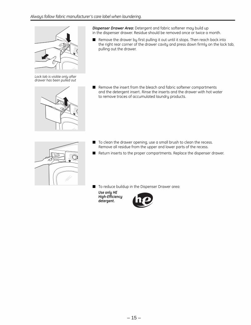
Dispenser Drawer Area: Detergent and fabric softener may build up in the dispenser drawer. Residue should be removed once or twice a month.
■ Remove the drawer by first pulling it out until it stops. Then reach back into the right rear corner of the drawer cavity and press down firmly on the lock tab,pulling out the drawer.
■ Remove the insert from the bleach and fabric softener compartments and the detergent insert. Rinse the inserts and the drawer with hot water to remove traces of accumulated laundry products.
■ To clean the drawer opening, use a small brush to clean the recess. Remove all residue from the upper and lower parts of the recess.
■ Return inserts to the proper compartments. Replace the dispenser drawer.
■ To reduce buildup in the Dispenser Drawer area:
Use only HE High-Efficiency detergent.
Lock tab is visible only afterdrawer has been pulled out
Always follow fabric manufacturer’s care label when laundering. ge.com

– 16 –
Operation Overview
Basic Wash Cycle
Note: See Component Locator Views for identifi cation and location of washer components.
After a load is placed in the wash basket:
If the SmartDispense pedestal is installed and the SmartDispense feature is used to dispense detergent and fabric softener, the user presses the POWER button and follows prompts shown on the VFD. (See owners manual.)
If the dispenser drawer is used to dispense detergent, bleach, and fabric softener, the user opens the dispenser drawer and positions the detergent selector for the type of detergent to be used.
Detergent is added to the detergent compartment. Detergent is added to the prewash compartment only if the PRE WASH cycle is selected.
Note: The prewash compartment is only fl ushed with water when the PRE WASH option is selected on the control.
If desired, add a measured amount (1/3 cup or less) of bleach into the bleach compartment.
If desired, add the recommended amount of fabric softener in the fabric softener compartment and dilute with water to the maximum fi ll line.
After adding laundry products, slowly close the dispenser drawer.
The user presses the POWER button to activate the display. If the display is active, press the POWER button to put washer into standby mode.
Rotate the cycle knob to the desired wash setting. When selecting WHITES/HEAVY DUTY, COLORS/NORMAL, ACTIVE WEAR, or DELICATES cycles, the following control default settings can be changed:
EXTRA RINSE•
PRE WASH•
SOIL LEVEL•
SPIN SPEED•
WASH TEMP•
Select EXTRA RINSE and PRE WASH options. Use the SIGNAL button to change the volume level of the end of cycle signal.
Select the SOIL LEVEL to increase or decrease wash time needed to remove different amounts of soil.
Select the SPIN SPEED to change the fi nal spin speed of the cycles. Follow the fabric manufacturer's care label when selecting spin speed.
Select the WASH TEMP to adjust the proper water temperature for the wash cycle. Follow the fabric manufacturer's care label when selecting wash temperature.
Press START/PAUSE to start the wash cycle. Each time the washer starts, a wake-up routine is initiated:
The door locks.1.
The wash basket briefl y tumbles in both 2. directions.
The door unlocks.3.
The door locks.4.
The fi ll cycle begins.5.
Water Fill
The washer automatically fi lls before tumbling, and maintains the proper fi ll level using a programmed adaptive fi ll. The machine will not tumble while fi lling.
Wash Water Temperature
The fi rst 10 seconds of fi ll is tap cold water only. If needed, the control board will cycle the water valves (water tempering) to achieve the target wash water temperature selected. Water tempering only occurs during the main wash cycle.
Tap Cold:
Cold water valve energized.• Tap cold never involves water tempering.•
Water temperature determined by supply • temperature.
All fi lls except main wash are tap cold.• (Continued Next Page)

– 17 –
Cold:
Cold water valve energized.•
Cold selection is tempered by default for main • wash.
Cold can be tempered by cycling of hot water • valve to achieve target temperature of 80°F (27°C).
Warm:
Hot and cold water valves energized.•
Warm can be tempered by cycling of hot and • cold valves to achieve target temperature of 105°F (40.5°C).
Warm selection is tempered by default for main • wash.
Hot:
Hot water valve energized.•
Hot can be tempered by cycling of cold water • valve to achieve target temperature of 120°F (49°C).
Hot selection is tempered by default main wash.•
Sanitize:
Hot water valve energized.•
Sanitize can be tempered by cycling of cold • water valve, or heater operation, to achieve target temperature of 160°F (71°C).
Tumble Wash
Wash routines are programmed by cycle. The only adjustment to the tumble routine is through cycle selection.
The basket rotates clockwise for a predetermined period of time at a predetermined speed. The basket pauses for a predetermined period of time. The basket rotates counterclockwise for a predetermined period of time at a predetermined speed. The length of tumble wash time is adaptive to the soil level programmed into the machine at the start of the cycle. Tumble speed is predetermined by cycle selection. For example:
Spin
The spin is designed to extract as much water and detergent as possible without harming fabrics. Speeds can be as slow as 90 rpm (out of balance default) to as high as 1300 rpm.
The available selection of spin speeds is controlled by cycle selection.
For example:
Selecting a spin speed modifi es fi nal spin only and must be made before fi nal spin takes place. The length of time required to achieve spin rpm is monitored by the control via the motor sensor. With a balanced load, if the selected spin speed cannot be achieved, the washer will default to highest speed attained and will increase spin time.
Off-balance load protection is programmed into the control board. If speed is not achieved, the spin routine halts. The washer tumbles to redistribute the load and attempts to spin again. After 5 attempts, if an off-balance load remains detected, spin speed defaults to the highest speed attained or 90 rpm (whichever is greater) for the remainder of the cycle.
Wash Cycle Selected
Spin Speed Selected
Final Spin Speed (RPM)
Whites/Heavy Duty No Spin 0 Low 400
Medium 1040 High 1140
Extra High 1300 Delicates No Spin 0
Low 400Medium 1040
High 1140Extra High n/a*
Wash Cycle Selected Tumble Speed (RPM) Whites/Heavy Duty 43
Delicates 35
*Extra High spin speed also not available on Handwash and Washable Wool cycles.

– 18 –
Component Locator Views
(Continued Next Page)
Top View
Thermistor Heating Element
Pump Outlet Hose
Pump
Damper
Motor
Front View
Tub Drain Hose
Inverter Located Behind Frame Front
Water Level ControlWater Valve
Line Filter
Dispenser Inlet Hose
Dispenser Vent Hose
Nozzle Hose
Water Valve Outlet Hose
3-Way Pipe
Dispenser Assembly
Power Control

– 19 –
Dispenser Drawer
Tub Drive Pulley
Belt
Motor
Component Locator Views (Con't)
Rear View

– 20 –
Control Board
Inverter Board
Circuit Board Connections
J3 Input from Power Board
DC Input Voltage from Control Board
120 VAC Input From Control Board
Output To Motor
CN3
Output to Control Board
(Continued Next Page)
VFD (Vacuum Fluorescent Display)

– 21 –
Power Supply Board (rear cover on)
J3
J4J11
J8
J79
J1
J2J5
J7
J1 L1 output to inverter, door lock switch, heater, and power fi lter J2 Softener pump, detergent pump motors J3 Door lock and unlock solenoids, dispenser motor, hot and cold water valves, water pump J4 7V and 12V to UI, LINbus, ground to UI and inverter, Ezlink tx, tx, and 5V to inverterJ5 Pressure switch: foam, main, and overfl ow switchesJ7 Detergent and softener level sensors J8 Bulk dispenser switch, dispense position switch, heater temperature thermistor, door lock switchJ11 L1 door lock switch, heater, N to inverter, N to bulk dispenser board, N to power fi lterJ79 Motor tachometer
J3
J4J11
J8
J79
J1
J2J5
J7
Power Supply Board (rear cover off)
– 22 –
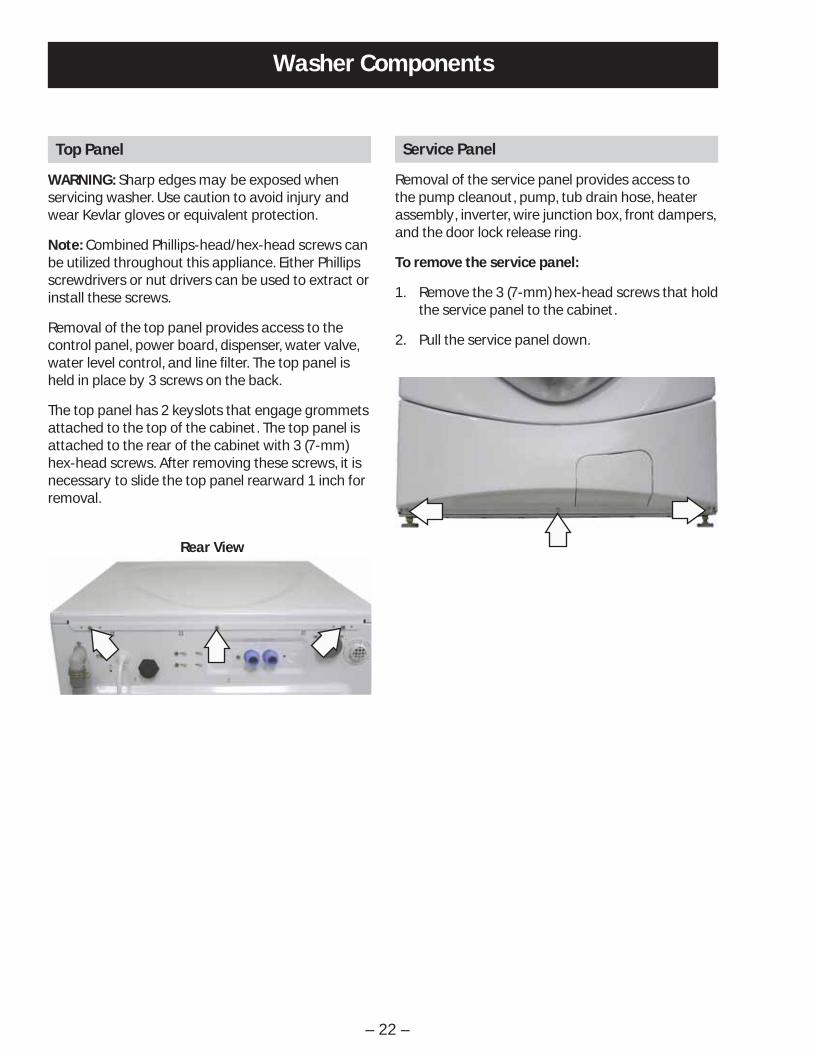
Washer Components
Service Panel
Removal of the service panel provides access to the pump cleanout, pump, tub drain hose, heater assembly, inverter, wire junction box, front dampers, and the door lock release ring.
To remove the service panel:
Remove the 3 (7-mm) hex-head screws that hold 1. the service panel to the cabinet.
Pull the service panel down.2.
Top Panel
WARNING: Sharp edges may be exposed when servicing washer. Use caution to avoid injury and wear Kevlar gloves or equivalent protection.
Note: Combined Phillips-head/hex-head screws can be utilized throughout this appliance. Either Phillips screwdrivers or nut drivers can be used to extract or install these screws.
Removal of the top panel provides access to the control panel, power board, dispenser, water valve, water level control, and line fi lter. The top panel is held in place by 3 screws on the back.
The top panel has 2 keyslots that engage grommets attached to the top of the cabinet. The top panel is attached to the rear of the cabinet with 3 (7-mm) hex-head screws. After removing these screws, it is necessary to slide the top panel rearward 1 inch for removal.
Rear View

– 23 –
6. Lift the panel from the cabinet.
7. Disconnect the wire harness from the control panel.
Note: When installing the control panel, place the panel pin in the locator hole in the top right-side of the front panel before engaging the tab.
5. Lift the top edge of the panel to disengage the tab that holds the top of the panel in place.
Remove the 3 (7-mm) hex-head screws that 4. attach the top of the control panel to the control panel brace.
Remove the 2 Phillips-head screws from the 3. control panel dispenser recess.
Lock Tab
Control Panel
The control panel is held in place with 5 Phillips-head screws and 1 tab.
To remove the control panel assembly:
Remove the top panel. (See 1. Top Panel.)
Pull the dispenser out to the stop position. Press 2. down on the lock tab. Pull the dispenser out.
Rear View
Tab

– 24 –
Control Board
The control board is mounted in a housing that is attached to the inside of the control panel. The control board and housing are replaced as an assembly. The control board assembly is held in place by 4 (6-mm) hex-head screws. The control board is programmed to recognize 6 modes of operation.
Mode Name DescriptionIdle No cycle is selected. All LEDs, VFD on front panel, load selections, and options are off.
The door is unlocked. The control board is ready to take input from user.
Standby A cycle is selected with the appropriate load selections and options. LEDs and VFD on the front panel are on. The door is unlocked. The control board is ready to take user input to either modify cycle selections or start a selected cycle.
Run The control board is executing the currently selected cycle. The door is locked.
Pause The control is stopped by the user during the execution of a cycle. LEDs and VFD on the front panel stay on. All loads are turned off. The door is unlocked. The control board is ready to take user input to either modify, resume, or cancel the cycle.
End of Cycle A cycle is completed. LEDs and VFD on the front panel stay on, all loads are turned off. The door is unlocked. The control board remains in this mode until the door is opened or after 2 hours have passed.
Fault The control board detected a critical failure condition. Certain functions of the washer will not operate. The VFD will show the fault code in the service test mode. The fault code can only be removed in the service test mode. (See Service Test Mode.)
Operation of the control board can be checked by using the service test mode. (See Service Test Mode.)
Specifi c failures associated with the control board can initiate error codes E1, E2, E10, and E26. (See Service Test Mode.)
(Continued Next Page)

– 25 –
To remove the control board assembly:
Remove the control panel. (See 1. Control Panel.)
Note: In the following step, the knob is held in place by 4 plastic clips and may require some effort to remove.
Remove the knob by pulling it straight out.2.
Remove the 4 (6-mm) hex-head screws that hold 3. the control board assembly to the control panel.
4. Remove the control board assembly from the control panel.
5. Remove the cycle selection buttons.
VFD (Vacuum Fluorescent Display)
To remove the VFD:
Remove the control panel. (See 1. Control Panel.)
Disconnect the wire harness from the VFD.2.
Press the 2 tabs that hold the VFD to the control 3. panel, lift the VFD and remove it from the 2 guides at the bottom.
Tab Tab
Disconnect
GuideGuide
Line Filter
The line fi lter helps to smooth out any fl uctuations in voltage, protecting the control board and providing more reliable operation. The line fi lter is installed on the interior side of the rear panel, and is located left of the water valve.
To check the line fi lter, look for the outer surface to be burnt by heat or a power surge. The fi lter resistance should be approximately 0 Ω between the black (top) wire terminals and 0 Ω between the white (bottom) wire terminals.
To remove the line fi lter:
Remove the single black (top) and single white 1. (bottom) wires.
Disconnect the wire harness by pressing the tab 2. and pulling outward.
Note: The ground wires attached to the line fi lter use releasing locking tabs.
Remove the 2 (7-mm) hex-head screws that hold 4. the fi lter to the frame.
Move the fi lter to the right. 5.
ELECTRICAL TERMINAL
RELEASE/LOCKING TAB
3. Press the locking tab on each terminal and remove the 2 ground wires.
Ground Wires

– 26 –
Remove the spring and wire from the gasket.3.
Pull the right side of the gasket away from the 4. front panel.
Pull the door lock to the opening and remove the 5. 3 wire harnesses.
Use a long-nose pliers to grasp the wire loop at 2. the spring location and expand it to clear the gasket.
Door Lock
The door lock contains a door switch and solenoid- operated locking and unlocking mechanism.
The door locks when a cycle is entered (wake-up routine) and during every cycle. The door unlocks at the completion of a cycle.
The door will not open when:
The foam switch is open •
Water temperature is above 130°F (54°C) •
Wash basket is rotating•
Specifi c failures associated with the door lock can initiate error codes E11 thru E13, and E28. (See Service Test Mode.)
The door lock is held to the front panel with 3 Phillips-head screws. The door lock is accessed from the front of the washer when the right side of the gasket is partially pulled back.
To remove the door lock :
Open the door and remove the 3 Phillips-head 1. screws that hold the door lock to the front panel.
Note: The door latch is solenoid-activated. It can remain locked after power is removed.

– 27 –
Door Strike
To remove the door strike:
Open the door.1.
Remove the 2 Phillips-head screws that hold the 2. door strike to the door frame cover.
Remove the door strike.3.
Note: The door strike position on the door can be horizontally adjusted 1/8-inch. Adjust the position of the door strike for best door closure.
Door Frame Cover
Door Strike
Front Panel
The front panel is hung on 2 hooks attached to the cabinet and held in place with four 1/4-in. hex-head and 2 Phillips-head screws. A gasket provides a watertight seal between the front panel and outer tub. The front of the gasket is secured to the front panel fl ange by a spring and wire located in the fold of the gasket. The door lock and wiring is attached to the front panel.
To remove the front panel:
Remove the control panel. (See 1. Control Panel.)
Remove the service panel. (See 2. Service Panel.)
Open the door. Remove the 3 Phillips-head 3. screws that hold the door lock to the front panel. (See Door Lock.)
Remove the spring and wire from the gasket. 4. (See Door Lock.)
Position the gasket behind the front panel door 5. opening. Close the door.
Remove the four 7-mm hex-head and 2 Phillips-6. head screws that attach the front panel to the cabinet.
Lift up then remove the front panel from the 2 7. hooks.

– 28 –
Dispenser Assembly
The dispenser assembly provides automatic dispensing of detergent, bleach, and fabric softener as long as the user fi lls the compartments prior to starting the washer.
The products added to the dispenser are diluted with water before they are dispensed into the wash tub. This is accomplished by a water diverter that sprays a controlled jet of water into the proper compartment at the correct time. The water diverter movement is provided by a motor-driven cam located on the dispenser tank. The diverter motor and water valve are operated by the control board.At the start of a cycle, after the wake-up routine is completed, the dispenser always moves into position before fi ll takes place.
Position Dispenser Function
1 Pre Wash
2 Wash
3 Fabric Softener
4 Bleach
Operation of the dispenser can be checked by using service test mode t15. (See Service Test Mode.)
Specifi c failures associated with the dispenser can initiate error code E9. (See Service Test Mode.)
Water Diverter
Motor Driven Cam
Dispenser Tank
Caution: When testing the diverter motor, DO NOT remove the wiring harness from the diverter motor unless replacing the motor assembly. The motor assembly has a special locking connector and the wiring harness will not stay reconnected if removed and reinstalled on the same motor.
To remove the dispenser assembly:
Remove the top and control panels. (See 1. Top and Control Panels.)
Remove the gasket inlet hose from the clip 2. attached to the dispenser.
Remove the 2 Phillips-head screws that attach 3. the diverter motor and clip to the dispenser tank. Place the motor and clip aside.
Clip
Diverter Motor
4. Mark the positions of the 3 bulk dispenser hoses connected to the dispenser.
5. Remove the water inlet, tub vent, and bulk dispenser inlet hoses from the dispenser:
Note: The water inlet, tub vent, and bulk dispenser inlet hoses are diffi cult to remove.
a. Squeeze each clamp and slide it back.
b. Carefully break each hose loose by inserting a small fl at blade screwdriver under the hose to break the seal.
c. Remove the hoses.

– 29 –(Continued Next Page)
Note: An inlet tube is placed between the inlet hose and the dispenser tank. The inlet tube provides proper water pressure to the dispenser and nozzle.When removing the inlet hose, the inlet tube may remain in the hose. Ensure the inlet tube is fully inserted into the tank inlet upon reassembly.
Inlet Hose
Inlet Tube
Tank Inlet
Dispenser Vent Hose
Bulk Dispenser Inlet Hoses
Bulk Hose Connections to Dispenser Tank
Middle Hose
Bottom Hose
Top Hose
6. Using either a Phillips-head screwdriver or a 7-mm hex-head nut driver, loosen the clamp and remove the dispenser outlet hose from the dispenser.
Note: Install the dispenser outlet hose with the hose indicator aligned with the dispenser tank protusion.
Note: Install the dispenser vent hose with the notch aligned on dispenser tank. Ensure that the seam remains aligned with the pointer on the outer tub.
Pointer
Seam
Notch
Protrusion
Indicator
Dispenser Outlet Hose

– 30 –
7. Remove the 2 Phillips-head screws that attach the dispenser to the front bracket.
8. Pull the dispenser towards the rear of the washer and disengage the dispenser from the front bracket.
Note: When installing the dispenser, ensure the dispenser guide pin is inserted into the slot in the side of the cabinet left side top brace and the 2 front pins are inserted in the holes in the front bracket.
Guide Pin Harness Removal
Dispenser Motor
The dispenser is operated by a 120-VAC, 60-Hz motor. The dispenser motor receives commands from the control board and controls dispenser operation.
Operation of the dispenser motor can be checked by using the Service Test Mode t12. (See Service Test Mode.)
Specifi c failures associated with the dispenser motor can initiate error codes E38, E39, and E62. (See Service Test Mode.)
To remove the dispenser motor:
Access the dispenser assembly. (See Dispenser Assembly.)
Caution: Lock tabs on the dispenser motor wiring harnesses are fragile. Tab breakage can occur if excessive release pressure is applied.
Note: In the following step, it can be helpful to insert a small fl at blade screwdriver (as shown) to remove the wire harnesses.
Carefully press the lock tab and disconnect the 1. 2 wire harnesses from the dispenser motor.
Remove the 2 Phillips-head screws that attach 2. the motor and gasket inlet hose clip to the dispenser tank. (See Dispenser Assembly.)
Lift the dispenser motor vertically from the 3. dispenser tank.
– 31 –
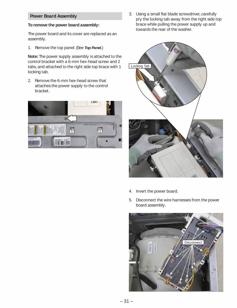
Power Board Assembly
To remove the power board assembly:
The power board and its cover are replaced as an assembly.
Remove the top panel. (See 1. Top Panel.)
Note: The power supply assembly is attached to the control bracket with a 6-mm hex-head screw and 2 tabs, and attached to the right side top brace with 1 locking tab.
2. Remove the 6-mm hex-head screw that attaches the power supply to the control bracket.
3. Using a small fl at blade screwdriver, carefully pry the locking tab away from the right side top brace while pulling the power supply up and towards the rear of the washer.
4. Invert the power board.
5. Disconnect the wire harnesses from the power board assembly.
Locking Tab
Disconnect

– 32 –
Water Level Control
The water level control is installed on the cabinet right side top brace. The water level control is connected by a hose to an air chamber attached to the bottom of the outer tub. The water level control consists of 3 internal switches that monitor 4 water level conditions.
When the water level rises in the outer tub, air is • trapped in the air chamber.
As the water level rises, the air pressure in the • air chamber increases.
The increased pressure operates the 3 internal • switches.
The washer has overfl ow protection and will • automatically pump out regardless of whether the washer is on or off, as long as the unit is plugged in. This action supersedes all other commands.
The 3 internal switches are identifi ed as foam, • main, and overfl ow. The 4 water level conditions monitored are empty, foam, main, and overfl ow.
Level Switch PositionFoam Main Overfl ow
Empty Closed Open OpenFoam Open Open OpenMain Open Closed Open
Overfl ow Open Closed Closed
Water Level Control Operation
When the machine is empty, the foam switch is closed and the motor circuit is disabled. When the main wash cycle is activated, the fi ll valve begins operating. The machine fi lls to the foam water level, the foam switch opens, and tumble begins. Water temperature is read by the thermistor and fi ll valve percentage of operation (water tempering) is calculated for the main wash. When calculated, and/or when the load absorbs water, the tumbling will pause. Fill will continue until the main water level is reached (Adaptive fi ll), the main switch closes, and main wash tumbling begins.
Water Levels
The foam water level, measured behind the baffl e, is approximately 1 3/4 -inches deep, and approximately 1-inch deep measured at the bottom center of the wash basket.
Foam Water Level
Main Water Level
The main water level, measured behind the baffl e, is approximately 2 3/4 -inches deep, and approximately 2- inches deep measured at the bottom center of the wash basket.
Foam
Main
Overfl ow
Water Level Control
212422313432 1211
(Continued Next Page)

– 33 –(Continued Next Page)
Overfl ow Water Level
Operation of the water level control can be checked by using service test mode t09. (See Service Test Mode.)
Specifi c failures associated with the water level control can initiate error codes E6 and E14. (See Service Test Mode.)
Pressure Tube
To remove the water level control:
Remove the top panel. (See 1. Top Panel.)
Press down the tabs, then disconnect each of 2. the 2 wire harnesses.
Remove the pressure tube.3.
Note: The pressure tube is diffi cult to remove.
a. Squeeze the clamp and slide it back.
b. Carefully break the hose loose by inserting a small fl at blade screwdriver under the hose to break the seal.
c. Remove the hose.
4. Lift wiring, rotate the water level control 1/4-turn clockwise, then pull it out from the cabinet.
Water Valve
The water valve assembly consists of a valve body and two solenoid coils. The water valve has a fl ow rate of 2.1 gallons (8 liters) per minute. It is inserted and retained in a cutout in the rear of the cabinet and held in place by a single 6-mm hex-head screw. It is only available as a complete assembly.
Each solenoid coil has an approximate resistance value of 1.1K Ω.
Operation of the water valve can be checked by using service test modes t11 and t12. (See Service Test Mode.)
Specifi c failures associated with the water valve can initiate error code E7. (See Service Test Mode.)
Tabs
Clamp
The overfl ow water level, measured at the bottom center of the wash basket, is approximately 7 1/2
inches deep. Overfl ow protection will occur at this water level.

– 34 –
To remove the water valve:
Remove the top panel. (See 1. Top Panel.)
2. Disconnect the black and blue wires and the orange wire from the cold water (C) solenoid.
3. Disconnect the 2 blue wires and the brown wire from the hot water (H) solenoid.
4. Disconnect the valve outlet hose:
Note: The valve outlet hose is diffi cult to remove.
a. Squeeze the clamp and slide it back.
b. Carefully break the hose loose by inserting a small fl at blade screwdriver under the hose to break the seal.
c. Remove the hose.
Cold Water Hot Water
Outlet Hose
6. Move the valve horizontally towards the hot indicator stamped on the back of the washer.
5. Remove the single (6-mm) hex-head screw that holds the valve to the cabinet.
Pump
The pump consists of a 120-VAC, 60-Hz motor, impeller, impeller housing, and a removable strainer that helps prevent foreign objects from entering the pump impeller and drain outlet.
The pump runs whenever the washer is in the • spin function of a cycle.
The pump runs if the water level control • overfl ow switch is closed and the washer is plugged in. (Overfl ow protection)
The pump is capable of eliminating 17 gallons • (64 liters) per minute.
Recommended minimum standpipe diameter is • 1 1/4 inches.
Standpipe maximum height is 96 inches, • measured from the fl oor at the washer location.
The pump motor has an approximate resistance • value of 10.6 Ω.
Operation of the pump can be checked by using service test mode t08. (See Service Test Mode.)
Specifi c failures associated with the pump can initiate error code E8. (See Service Test Mode.)
(Continued Next Page)

– 35 –
To remove the pump:
Remove the front panel. (See 1. Front Panel.)
Caution: Under normal conditions, approximately 1 quart of water will drain out when the pump cleanout is removed.
Place a shallow pan under the drain cleanout.2.
Turn the pump cleanout counterclockwise 3. approximately 2 turns, then pull outward.
Strainer
Note: Remove any debris or foreign objects from the strainer and interior of the pump before reinstalling.
Remove the drain hoses from the pump:4.
Note: The drain hoses are diffi cult to remove.
Squeeze each clamp and slide it back.a.
Carefully break each hose loose by inserting b. a small fl at blade screwdriver under the hose to break the seal.
Remove the tub outlet hose from the pump c. inlet.
Remove the drain hose from the pump d. outlet.
Disconnect the 2 wires from the pump.5.
Remove the 2 Phillips-head screws that hold the 6. pump to the chassis.
Pull the pump rearward to clear the 2 locator 7. pins from the 2 grommets in the front frame.
Drain Hose
Tub Outlet Hose
Pump Wires
Remove the pump through the enlarged 8. opening on the left side of the front frame.
Note: Before installing the clamp, align the notch in the drain hose with the raised ridge on the pump outlet.
Locator Pins
Ridge
Notch

– 36 –
Thermistor10-mm Hex-Head Nut
Heater Assembly
The heater assembly is located above the pump, • and is accessed from the front of the washer.
The heater assembly consists of a heating • element and a water temperature thermistor.
The heater can operate in • WHITES/HEAVY DUTY, or STAIN INSPECTOR wash cycles, and when the sanitize wash temperature is selected.
The heater assembly is held in place by a • bracket attached to the inside of the outer tub and a 10-mm nut which compresses a rubber gasket to the tub opening.
When the 10-mm hex nut is tightened, it • squeezes the rubber gasket between 2 mounting plates to seal the heater assembly to the opening of the tub.
The hex nut is set from the factory at 31 in. lbs • of torque.
Operation of the heater assembly can be checked by using service test mode t10. (See Service Test Mode.)
Specifi c failures associated with the heater assembly can initiate error codes E4 and E5. (See Service Test Mode.)
Heating Element Specifi cations:
120 VAC• 970 Watts• Approximately 8 AmpsApproximately 8 Amps• • Approximately 15 • Ω
Thermistor Specifi cations:
12 K• Ω at 75°F (24°C).
Resistance goes down as temperature goes up.•
To remove the thermistor:
Remove the service panel. (See 1. Service Panel.)
Drain the washer using the pump cleanout. (See 2. Pump.)
Disconnect the wire harness from the thermistor.3.
Loosen the 10-mm hex nut until it is fl ush with 4. the end of the stud.
Push inward on the 10-mm hex nut to relax the 5. rubber gasket.
Grasp the thermistor and pull outward.6.
Thermistor Removal
Thermistor
(Continued Next Page)

– 37 –
To replace the thermistor:
Push the thermistor into the rubber gasket until 1. fully seated.
Note: Ensure heater assembly is fully seated in the tub.
Use a torque wrench to tighten the 10-mm hex 2. nut to 31-in. lbs of torque.
CAUTION: Proper torque must be applied to the 10-mm hex nut to assure a proper seal. Under-torquing could cause water leakage; over-torquing could cause the tub to crack.
Reconnect the wire harness to the thermistor.3.
To remove the heater assembly:
Remove the service panel. (See 1. Service Panel.)
Drain the washer using the pump cleanout. (See 2. Pump.)
Disconnect the blue and the purple wires from 3. the heater and the wire harness from the thermistor.
Loosen the 10-mm hex nut until it is fl ush with 4. the end of the stud.
Torque Wrench
Push inward on the 10-mm hex nut to relax the 5. rubber gasket.
Grasp the heater assembly and pull outward.6.
Heater Assembly Removal
Heater Assembly
To reinstall the heater assembly:
Slide the heater assembly into the tub opening 1. and inside the bracket attached to the outer tub.
Seat the heater assembly in the tub opening.2.
Use a torque wrench to tighten the 10-mm hex 3. nut to 31-in. lbs of torque.
CAUTION: Proper torque must be applied to the 10-mm hex nut to assure a proper seal. Under-torquing could cause water leakage; over-torquing could cause the tub to crack.
Reconnect the wire harness to the thermistor 4. and the blue and the purple wires to the heater.
Bracket

– 38 –
Inverter
The inverter receives commands from the control board and controls motor operation. The inverter is enclosed in a protective housing and is located on the chassis, under the left side of the outer tub. It is inserted in 2 guides at the rear and held in place by a single Phillips-head screw at the front.
For the inverter to operate the motor correctly requires a supply voltage of 120 VAC, DC input from the control board, and the three motor windings intact.
To check the inverter:
Remove the service panel. (See 1. Service Panel.)
Press the 4 tabs inward and remove the junction 2. box cover.
Enter test mode t04, t13, or t14.3.
Check for 120 VAC between the blue and red 4. wires at the AC input harness.
Note: The 120 VAC inverter supply voltage is present only when the motor is supposed to be operating.
Unplug washer, then check motor resistance. 5. (See Motor Assembly.)
If 120 VAC is present at the AC input harness and 6. motor resistance is correct, replace the inverter.
Note: If the inverter overheats, the washer will stop for 5 minutes.
Disconnect the motor wire harness.4.
Note
The motor wire harness is soldered to the • inverter. Any fault in the inverter or motor wire harness requires inverter replacement.
The motor ground wire connector utilizes a • releasing locking tab.
To remove the inverter:
Remove the service panel. (See 1. Service Panel.)
Press the 4 tabs inward and remove the junction 2. box cover.
Disconnect the AC and DC input wire harnesses 3. contained in the junction box.
Junction Box Cover
Tab (1 of 4)
AC Input DC Input
Junction Box
ELECTRICAL TERMINALRELEASE/LOCKING TAB
(Continued Next Page)

– 39 –
Slide the inverter rearward to clear the guides 8. that hold the rear of the inverter to the chassis.
Remove the inverter through the enlarged 9. opening on the left side of the front frame.
Remove the single Phillips-head screw that 7. holds the right front leg of the inverter to the base pan.
Ground Wire
Wire Tie
Press the lock tab and remove the motor ground 5. wire.
Remove the plastic wire tie that holds the motor 6. wiring in place.
Inverter
Wire Harness
Belt
To remove the belt:
Remove the four 6-mm screws from the cabinet 1. rear cover.
Pull the cover outward from the middle. 2.
Remove the belt by turning the tub drive pulley 3. and rolling the belt off the pulley.
Note: The belt is elastic and is designed to be removed and installed in this manner.
Belt
Tub Drive Pulley

– 40 –(Continued Next Page)
Motor Assembly
The motor assembly consists of a reversible, variable speed, 3-phase induction DC motor, and sensor. The motor drives the tub drive pulley with a 7-rib belt. The sensor monitors motor rpm and is connected to the control board. The motor assembly is checked from the front of the washer and removed from the rear.
There are 2 methods to check the motor assembly.
Method A:
Remove the service panel. (See 1. Service Panel.)
Disconnect the motor wire harness.2.
On the motor plug, check for an approximate resistance value of 6 ohms between any two of the three wires:
Blue to white - 6 • Ω
Blue to red - 6 • Ω
White to red - 6 • Ω
The sensor has a resistance value of • approximately 118 Ω between the two orange wires.
Operation of the motor assembly can be checked by using service test modes t04, t13, and t14. (See Service Test Mode.)
Specifi c failures associated with the motor assembly can initiate error codes E3, and E15 through E25.(See Service Test Mode.)
Method B:
Remove the service panel. (See 1. Service Panel.)
Remove the single Phillips-head screw that 2. holds the right front leg of the inverter to the base pan.
Slide the inverter rearward to clear the guides 3. that hold the rear of the inverter to the base pan.
Position the inverter to access the inverter 4. board.
Wash Basket Pulley
To remove the wash basket pulley:
Remove the belt. (See 1. Belt.)
Remove the 24-mm drive nut that holds the tub 2. drive pulley to the wash basket. Remove the pulley.
Caution: The nylon locking material used inside the drive nut will be damaged upon removal. Use replacement drive nut (Part # WH02X10211) when reinstalling the tub drive pulley. Use a torque wrench to tighten the 24-mm hex nut to 44-ft. lbs of torque.
Drive Nut

– 41 –
Note: The sensor and sensor wiring can be checked at the power board assembly. Check for a resistance value of approximately 118 Ω resistance between the 2 yellow wires located on the wire harness located at J79.
On the inverter board, check for an approximate 5. resistance value of 6 ohms between any two of the three terminals:
A to B (Blue to white) - 6 • Ω
A to C (Blue to red) - 6 • Ω
B to C (White to red) - 6 • Ω
BC
A
J79
(Continued Next Page)
To remove the motor:
Remove the belt. (See 1. Belt.)
Remove the 2. 1/2 -in. bolt from the threaded plate that holds the motor arm to the outer tub.
Slot
Plate
Motor Arm
Note
The threaded plate can fall out of the recessed • slot in the motor mount. Ensure this plate is reinserted in the slot upon reassembly.
When reinstalling bolt, apply Locktite (Part # • WX5X1005) to bolt threads. Ensure motor arm is at lowest position under motor bolt before tightening.

– 42 –
Rock motor rearward to clear the motor mounts 5. from the outer tub. Place the motor on the washer chassis.
Disconnect the motor wire harness.6.
Note: The motor ground wire connector utilizes a releasing locking tab.
Door
To remove the door components:
Note: The hinge cover is attached to the door with 2 Phillips-head screws and 3 tabs located on the inside.
Remove the 2 Phillips-head screws.1.
3. Remove the 2 Phillips-head screws that hold the door to the hinge door plate.
(Continued Next Page)
Hinge Cover
2. Lift the right-side of the hinge cover and slide it to the right.
Tab
Tab
Tab
ELECTRICAL TERMINALRELEASE/LOCKING TAB
6. Press the lock tab and remove the motor ground wire.
7. Remove the plastic wire tie that holds the motor wire harness and ground wire to the motor.
8. Lift the motor out of the washer.
Note: When reinstalling the belt, ensure the belt is positioned to track in the 7 outer grooves of the motor pulley.

– 43 –
5. Lift and unsnap the door cover from the door frame.
6. Lift the door glass out of the door frame.
Note: Place the door on a soft, protected fl at surface so that the door glass faces up. (The door should rest on the handle side.)
4. Remove the 10 Phillips-head screws that hold the door cover and door strike to the door frame.
Door Glass
7. Remove the 9 Phillips-head screws that attach the protect cover and ring to the door frame.
8. Lift and remove the protect cover and ring.
Note: The door handle and door frame are replaced as an assembly. (Part # WH46X10210)
Door Handle
Door Frame
Protect Cover
Ring

– 44 –
3. Remove the 3 Phillips-head screws that hold the door hinge to the front panel.
Door Hinge
To remove the door hinge:
Remove the door. (See 1. Door.)
Grasp the hinge pin with a pair of pliers and pull 2. the pin out of the hinge. Remove the door hinge plate.
Note: It may be helpful to drive the hinge pin upward using a punch.
Push the tub assembly back while pressing the 6. hinge arm inward and carefully remove the door hinge through the opening.
Hinge Pin
Door Hinge Plate
Door Hinge
4. Remove the gasket from the front panel. (See Front Panel.)
5. Push and fold the left side of the gasket inside the wash basket.
Note: The door hinge is attached to the front panel with 3 Phillips-head screws in front and 3 tabs on the back. After removing the screws, it may be necessary to strike the bottom of the hinge (as shown) to free it from the front panel.
(Continued Next Page)
– 45 –(Continued Next Page)
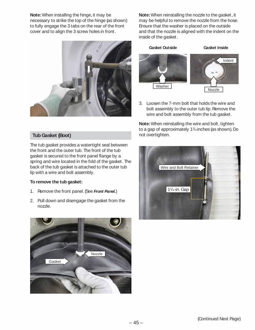
Tub Gasket (Boot)
The tub gasket provides a watertight seal between the front and the outer tub. The front of the tub gasket is secured to the front panel fl ange by a spring and wire located in the fold of the gasket. The back of the tub gasket is attached to the outer tub lip with a wire and bolt assembly.
To remove the tub gasket:
Remove the front panel. (See 1. Front Panel.)
Pull down and disengage the gasket from the 2. nozzle.
Gasket
Nozzle
Note: When installing the hinge, it may be necessary to strike the top of the hinge (as shown) to fully engage the 3 tabs on the rear of the front cover and to align the 3 screw holes in front.
Note: When reinstalling the nozzle to the gasket, it may be helpful to remove the nozzle from the hose. Ensure that the washer is placed on the outside and that the nozzle is aligned with the indent on the inside of the gasket.
Gasket Outside Gasket Inside
Washer
3. Loosen the 7-mm bolt that holds the wire and bolt assembly to the outer tub lip. Remove the wire and bolt assembly from the tub gasket.
Note: When reinstalling the wire and bolt, tighten to a gap of approximately 11/4 inches (as shown). Do not overtighten.
Wire and Bolt Retainer
11/4 -in. Gap
Indent
Nozzle

– 46 –
4. Pull the tub gasket off the outer tub lip.
Note: When reinstalling the tub gasket on the outer tub, align the indicator on the top of the gasket with the arrow located on the top of the tub. Also ensure that the notch in the bottom of the gasket is located at the 6 o'clock position before tightening the wire and bolt assembly.
OuterTubLip
Notch
Indicator
Arrow
Top of Gasket
Bottom of Gasket
Dampers
Each of the 4 dampers are secured to the outer tub by a gray upper bushing that locks in a slot in the outer tub. Each damper is held to the chassis with a plastic pin.
To remove the dampers:
Caution: Do not twist the damper cylinder by hand to remove. Stress may result in the damper developing noise at a later date.
Remove the service panel. (See 1. Service Panel.)
Rotate the gray upper bushing a quarter-turn 2. clockwise (as viewed from the top) using a 6-in. adjustable crescent wrench with a jaw opening of approximately 7/8 inch.
Compress and remove the damper from the slot 3. in the outer tub.
Damper
Gray Upper Bushing
Wrench Location
(Continued Next Page)

– 47 –
4. Remove the pin that secures each damper to the chassis by pressing the lock tab while pulling the pin out.
Note: It may be helpful to tap the pins out with a small hammer while pressing on the lock tabs.
Tab
To replace the dampers:
Note: The pin will be damaged when removed from the chassis. Be sure to install the new pin supplied with the replacement damper.
Insert and fully seat the pin that secures each 1. damper to the chassis.
Note: It may be helpful to tap the pins into the chassis with a small hammer.
Extend and fully insert the damper into the slot 2. in the outer tub.
Rotate the gray upper bushing a quarter-turn 3. counterclockwise (as viewed from the top), using a 6-in. adjustable crescent wrench with a jaw opening of approximately 7/8 inch.
Note: Ensure the 2 lock tabs on the gray upper bushing are in the square holes in the outer tub.
Pin
Wash Basket
The wash basket is contained inside the outer tub. The wash basket is rotated by a belt-driven tub-drive pulley. A drive nut attaches the tub drive pulley to the wash basket. To remove the wash basket it will become necessary to separate the outer tub halves.
To remove the wash basket:
Drain the washer using the pump cleanout. (See 1. Pump.)
Remove the top, control, and service panels. 2. (See Top, Control, and Service Panels.)
Remove the wash basket pulley. (See 3. Wash Basket Pulley.)
Compress the tabs and remove the 2 wire 4. retainers that attach the power board assembly wiring to the front bracket.
5. Remove the power supply assembly from the control bracket and right side brace and set it aside. (See Power Supply Assembly.)
6. Remove the dispenser vent hose from the outer tub, and the gasket inlet hose from the clip. (See Dispenser.)
7. Remove the dispenser outlet hose from the dispenser. (See Dispenser.)
(Continued Next Page)

– 48 –
9. Remove the 2 Phillips-head screws that attach the dispenser to the front frame and set the dispenser aside.
10. Pull down and disengage the gasket from the nozzle. (See Tub Gasket (Boot).)
11. Remove the remaining 8 Phillips-head screws that attach the front bracket and control panel rear cover and set them towards the top rear of the washer.
8. Remove the dispenser motor wiring from the retainer located on the left side brace.
Retainer
12. Remove the 8 (13-mm) nuts and washers from the bolts that hold the front top and bottom counterweights to the front of the outer tub.
13. Remove the counterweights and the 8 bolts from the slots in the outer tub.
(Continued Next Page)

– 49 –
14. Disconnect the heater assembly wires.
15. Remove the plastic wire tie that holds the heater assembly wiring and the tub ground wire to the outer tub.
16. Remove the front dampers from the outer tub. (See Dampers.) Compress the dampers and position them towards the outside of the cabinet.
Disconnect
Wire Tie
17. Remove the 26 (8-mm) hex-head screws from the perimeter of the outer tub.
1 of 26
18. Press the 2 tabs located on the sides of the outer tub inward and remove the outer tub front half.
Note:
Install new outer tub seal (Part # WH08X10023) •whenever tub halves have been separated.
Use a torque wrench to tighten the 26 tub •screws to 45-in. lbs of torque.
When installing outer tub front half, ensure the •heater is inserted inside the bracket attached to the rear half of the outer tub. (See Heater Assembly.)
19. Pull the wash basket out of the outer tub rear half.
Installing Front Counterweights
When installing the front counterweights, make sure the short bolts are used to attach the top counterweight and the long bolts are used to attach the bottom counterweight. Insert the bolts into the slots with the beveled edges outward.
Use a torque wrench to tighten the 8 (10-mm) nuts to 142-in. lbs of torque.
TapeTape
Note: To make installation of the front bottom counterweight easier, secure the placement of the bottom bolts with electrical tape.
Beveled Edges

– 50 –
Outer Tub Assembly and Suspension
The outer tub assembly is constructed in two halves and contains the wash basket. The bearing and seal assembly is part of the outer tub rear half. The outer tub assembly is supported by 2 suspension springs and 4 dampers. Each spring is located between the top of the tub assembly and a cabinet top brace, one on each side. Washer stabilization is achieved by the use of 4 dampers that are located between the bottom of the tub assembly and chassis, 2 per side.
To remove the outer tub assembly:
WARNING: The outer tub assembly is heavy and requires two people to remove it from the washer cabinet. Care should be taken when removing and installing the outer tub assembly.
Drain the washer using the pump cleanout. (See 1. Pump.)
Remove the top, control, service, and front 2. panels. (See Top Panel, Control Panel, Service Panel, and Front Panel.)
Compress the tabs and remove the 2 wire 3. retainers that attach the power board assembly wiring to the front bracket.
10. Remove the dispenser outlet hose from the vent pipe.
Note: The dispenser outlet hose is diffi cult to remove.
a. Squeeze the clamp and slide it back.
b. Carefully break the tub vent hose loose by inserting a small fl at blade screwdriver under the hose to break the seal.
c. Remove the hose.
Tub Vent Pipe
5. Remove the dispenser vent hose from the outer tub. (See Dispenser.)
6. Remove the dispenser outlet hose from the dispenser. (See Dispenser.)
7. Remove the 2 Phillips-head screws that attach the dispenser to the front frame and set the dispenser aside. (See Dispenser.)
8. Pull down and disengage the tub gasket from the nozzle. (See Tub Gasket (Boot).)
9. Remove the remaining 8 Phillips-head screws that attach the front bracket and control panel rear cover and set the front bracket aside.
4. Remove the power supply assembly from the control bracket and right-side brace and set it aside. (See Power Board Assembly.)
(Continued Next Page)

– 51 –
11. Remove the pressure tube from the water level control.
12. Disconnect the heater assembly wires.
13. Remove the plastic wire tie that holds the heater assembly wiring and the tub ground wire to the outer tub.
Note: The motor ground wire connector utilizes a releasing locking tab.
Ground Wire
ELECTRICAL TERMINALRELEASE/LOCKING TAB
14. Disconnect the motor wire harness, motor ground wire, and remove the plastic wire tie that holds the wiring to the motor.
15. Remove the tub drain hose from the pump.
16. Remove the 4 Phillips-head screws from the cabinet rear cover.
17. Pull the cover outward from the middle.
18. Remove the Phillips-head screw that holds the tub ground wire. Remove the ground wire from the outer tub wire guides.
19. Remove the front top and bottom counterweights. (See Wash Basket.)
20. Remove the 4 dampers from the outer tub. (See Dampers.)
21. Compress the dampers and position them towards the outside of the cabinet.
22. Lift the outer tub assembly up, then release the 2 suspension springs from the slotted plastic inserts in the cabinet top braces.
23. Carefully remove the tub assembly out through the front of the cabinet.
Note: When installing the tub assembly, hook each of the suspension springs in the forward hole of the outer tub spring mounts and the rear slot in the insert.
Insert
Front of Washer
Suspension Spring
Outer Tub
Spring Mount
Forward Hole

– 52 –
Service Test Mode
The washer control has a service test mode that can be utilized by the service technician in order to test critical components and to access error codes. This test mode will help the service technician to quickly identify failed or improper operation of washer components.
Caution: Testing is accomplished through built-in test procedures. Unplugging components for testing can damage component connections.
The washer must be in idle mode (blue screen is blank), before entering the test mode. Idle mode occurs when the washer has completed a cycle. If the cycle is interrupted, the washer will drain water when the power is re-applied. The water level switch must reset BEFORE the test mode can be entered. If water remains in the washer, manually drain the washer to reset the water level switch. A failed water level switch can cause an inability to enter the test mode.
Test Mode Description
t01 Confi gure UI (User Interface) Allows changing the confi guration of the control for different models.
t02 Error Codes Checks for any error codes reported by the controls.
t03 Version Information Checks the software version.t04 Vibration Test Tests the washer vibration by spinning to the extra
high spin speed as fast as possible. Note: No out of balance detection will be performed here, so the washer will spin up regardless of the out of balance that is placed in the drum.
t05 EEPROM Test Checks the memory on the user interface control board, then the memory on the Power Board.
t06 UI Test Verifi es all LEDs operate correctly.
t07 Key Continuity Verifi es that each key operates correctly.
t08 Pump Test Test drain pump.t09 Water Level Sensor Fills to all 3 levels; then pumps out water.
t10 Temp & Heater Verifi es that both the Thermistor and Heater work.t11 Hot Water Test Verifi es hot water valve turns on/off.t12 Cold Water Test Verifi es cold water valve turns on/off.t13 Tumble Test Verifi es washer tumbles (i.e., Wash Cycle).t14 Spin Test Verifi es washer spins. Note: No out-of-balance
detection will be performed here, so the washer will spin up regardless of any out-of-balance condition in the drum.
(Continued Next Page)
To enter the test mode: To exit the test mode:Press 1. POWER button to clear any current cycles.
Note: The display must be blank to proceed.
2. Press EXTRA RINSE-DELAY START-EXTRA RINSE-DELAY START
A washer left in the test mode will exit the test mode and unlock the door after approximately 30 minutes.
Press POWER button.

– 53 –
Test Mode Description
t15 Dispenser TestVerifi es the dispenser motor works and can locate all 4 dispenser positions.
t16 Bulk Pumps Test Verifi es all the Smart Dispenser Pumps work.
t17 Bulk Sensors Test Verifi es all the Smart Dispenser Sensors work.
t18 AutoSpin Profi le Tests each spin speed of the washer. Note: No out-of-balance detection will be performed here, so the washer will spin up regardless of any out-of- balance condition in the drum.
t19 Bulk Manual Priming Manually initiates the priming of the Smart Dispenser pumps.
t20 Bulk Primed Status Checks the control status of the prime status of the pumps and allows the user to change/reset the prime status.

– 54 –
Service Mode Test Sequencet01 Confi gure UI Enter Displays “confi gure UI”
Power Returns to service mode screent02 Error Codes Enter Displays error codes
Start/Pause
Clears highlighted error code from machine
Power Returns to service mode screent03 Version Info Enter Displays the current version of software
Power Returns to service mode screent04 Vibration
TestEnter Spins up to 1300 rpm; then goes back to service mode screenPower Interrupts and returns to service mode
t05 EEProm Test Enter Displays “test in progress” for a while; then displays UI Memory statusStart Displays PB statusPower Returns to service mode screen
t06 UI Test Enter Lights up LEDs on the left side of UI and VFD; then lights up the right side LEDs
Power Returns to service mode screent07 Key
ContinuityEnter Begins testingAny Button but Power
Beep sounds as button is pressed
Power Returns to service mode screent08 Pump Test Enter Begins running the drain pump
Power Interrupts draining and returns to service modet09 Water Level
SensorEnter Unit begins to drain. When draining is complete, displays “Tub Empty”Start Fills to foam level. Displays “Tub Empty” until fi ll is complete; then shows
“Foam Level”Start Fills to normal level. Displays “Foam Level” until fi ll is complete, then
shows “Normal Wash Level”Start Fills to overfl ow level. Display shows “Normal Wash Level” until fi ll is
complete. When overfl ow level is reached, the pump begins to drain out the water.
Power Drains and returns to service modet10 Temp Sensor
and HeaterEnter Displays “baseline” and “current” temperature. Unit fi lls with water and
gets heatedPower Drains and returns to service mode screen
t11 Hot Water Valve Test
Enter Fills with hot water. Display shows “Hot Water On”
Power Drains and returns to service mode screent12 Cold Water
Valve TestEnter Fills with cold water. Display shows “Cold Water On”Power Drains and returns to service mode screen
t13 Tumble Test Enter Unit tumblesPower Returns to service mode screen
(Continued Next Page)
The following tables show the diagnostic tests and the button sequence that is required to perform them.

– 55 –
Service Mode Test Sequencet14 Spin Test Enter Displays “estimated” and “current” rpm. Unit begins spinning at 410 rpm
Start Ramps up to 1050 rpmStart Ramps up to 1150 rpmStart Ramps up to 1300 rpmPower Ramps down and returns to service mode screen
t15 Dispenser Test
Enter Displays “pre-wash” and dispenser moves to position 1Start Displays “main detergent” and dispenser moves to position 2Start Displays “bleach” and dispenser moves to position 4Start Displays “fabric softener” and dispenser moves to position 3Start Repeats above sequence, starting with “pre-wash”Power Drains and returns to service mode screen
t16 Bulk Pumps Test
Enter Displays “left detergent pump”; water fi lls and primes left detergentStart Displays “softener pump” and begins primingStart Displays “right det pump” and begins primingStart Continues cycling through the bulk pumpsPower Drains and returns to service mode screen
t17 Bulk Sensors Test
Enter Displays the status of Left Detergent, Softener and Right DetergentPower Returns to service mode screen
t18 Auto Spin Profi le
Enter Slowly ramps up to 90, then 120, then 410Power Interrupts and returns to service mode screen
t19 Bulk Manual Priming
Enter Displays “prime left detergent,” “prime softener,” prime right detergent” with one highlighted
Enter Begins priming selected, with water on to rinse it from dispenser drawerPower Drains; then returns to service mode screen
t20 Bulk Primed Status
Enter Displays “left detergent pump,” “softener pump,” "right detergent pump” with one highlighted
Enter Displays “left det primed status”; choose status “yes” (lines primed) or “no” (lines not primed)
Enter Returns back to “Bulk Primed Status”
Power Returns to service mode screen

– 56 –
Error Codes
(Continued Next Page)
Error Code Description ActionE1 UI EEPROM E2 Power EEPROM
Internal problem with UI or MC board
Replace board as necessary.•
E4 Thermistor Short
E5 Thermistor Open
Water Temperature Sensor Problem
Check integrity of wiring and connections between main • control and Thermistor Assembly.Using ohmmeter, measure Thermistor resistance. If outside • expected range, replace Thermistor Assembly.
IF ABOVE STEPS DO NOT CLEAR THE PROBLEM:Replace the main control.•
E6 Pressure Switch
Water Level Sensor Problem
Check integrity of wiring and connections between main • control and Water Level Sensor.Check integrity of Water Level Sensor; replace if necessary.• Check drain system.•
IF ABOVE STEPS DO NOT CLEAR THE PROBLEM:Replace the main control.•
E7 Slow Fill Fill Problem Ensure manual water valves are fully open.• Check if water strainers on solenoid valve assembly are • clogged.Check for obstructions inside inlet water hoses.• Ensure solenoid valves do not leak when the valves are de-• energized and the washer is powered down.Measure coil resistance for both valves. If outside range • (1000–1250 ohms at room temp.), replace solenoid valve assembly.
IF ABOVE STEPS DO NOT CLEAR THE PROBLEM:Replace solenoid valve assembly.•
E8 Drain System Drain Problem Ensure pump strainer is clean and free of debris.• Check for obstruction inside the drain hose.• Check pump impeller blades and bearing; if evidence of • blade damage or seized bearings are present, replace the pump.Check the electrical connections at the pump motor and • harness.Measure pump motor resistance. If outside range (9–14 • ohms at room temp.), replace the pump.
E9 Dispenser Motor
Dispenser Problem Check for obstruction in dispenser mechanism and • linkages.Check the electrical connections at the motor feedback • switch and in the harness.Check the electrical connections of water valves in the • harness.
IF ABOVE STEPS DO NOT CLEAR THE PROBLEM:Replace dispenser motor assembly.•
NOTE: It’s important to note error codes should only be used to help identify components which require testing. Never replace a part based solely on an error code. The control can generate a false error if the right conditions exist. Use the code only as a reference and always check the component before replacing.
– 57 –(Continued Next Page)
Error Code Description ActionE10 Motor Comm Interface
Communication Problem Between Machine Control and Motor Drive
Check integrity of wiring and connections between main • control and motor drive.Clear error code and run a cycle.• If fault persists and reappears, replace the Machine • Control.
E11 Door LockE12 Door UnlockE13 Door OpenE28 Unexpected
Door Lock Assembly Problems
Check integrity of wiring and connections between main • control and Door Lock mechanism.Investigate Door Lock mechanism; check door • microswitch operation, lock and unlock solenoid continuity and contact integrity; replace Door Lock mechanism if necessary.IF ABOVE STEPS DO NOT CLEAR THE PROBLEM:• Replace the main control.•
E14 Overfl ow Error Overfl ow level was reached
Check valve for any signs of leaks.• Check integrity of Water Level Sensor. Replace if • necessary.
E15 Open Circuit Open circuit in any of three motor phases detected
No speed info present and bridge will be turned off immediately
Motor will coast down
Drive will preserve non-zero speed info during the stop check stage
Check integrity of wire connections between the Motor Drive Control and the motor.
Clear fault and run cycle. If fault persists and reappears, replace the motor drive.
E16 Over Trip
E18 Heatsink Over Temp
E19 Motor Over Temp
E20 Overload Current
E21 Overload Power
Motor Drive operation above design limits
Ensure all 4 shipping bolts have been properly removed.•
Remove all foreign objects that may be lodged between • inner and outer baskets.
Look for signs of seized bearing(s) on basket and drum • motor. Replace components as necessary.
Inspect condition and mounting of door gasket. Replace • and re-mount as necessary.
Ensure inner basket (drum) can rotate freely.•
IF ABOVE STEPS DO NOT CLEAR THE PROBLEM:
Replace motor drive or drum motor.•
Door Unlock Detected

– 58 –
Error Code Description ActionE22 Over Volts
E23 Under Volts
E24 Under Volts After Start
E25 Power Up
E3 Inverter EEPROM Fault Event
E17 ADC Fault Event
Motor Drive Internal Problems
Measure AC outlet voltage; ensure correct range (120V to • 132V AC).
Check electrical connections at the motor drive.•
Check harness integrity between main control and • motor drive.
Unplug the unit, wait 30 seconds and restart the unit.•
If the fault persists and reappears, replace the motor • drive.
E26 LIN Comm Fail There is a problem with the Communication between the Machine Control and the User Interface Control
Check the integrity of the wiring between the Machine • Control Board and the User Interface.
Clear the fault and run the cycle. If fault persists and • reappears, replace the Machine Control.

– 59 –
Schematic
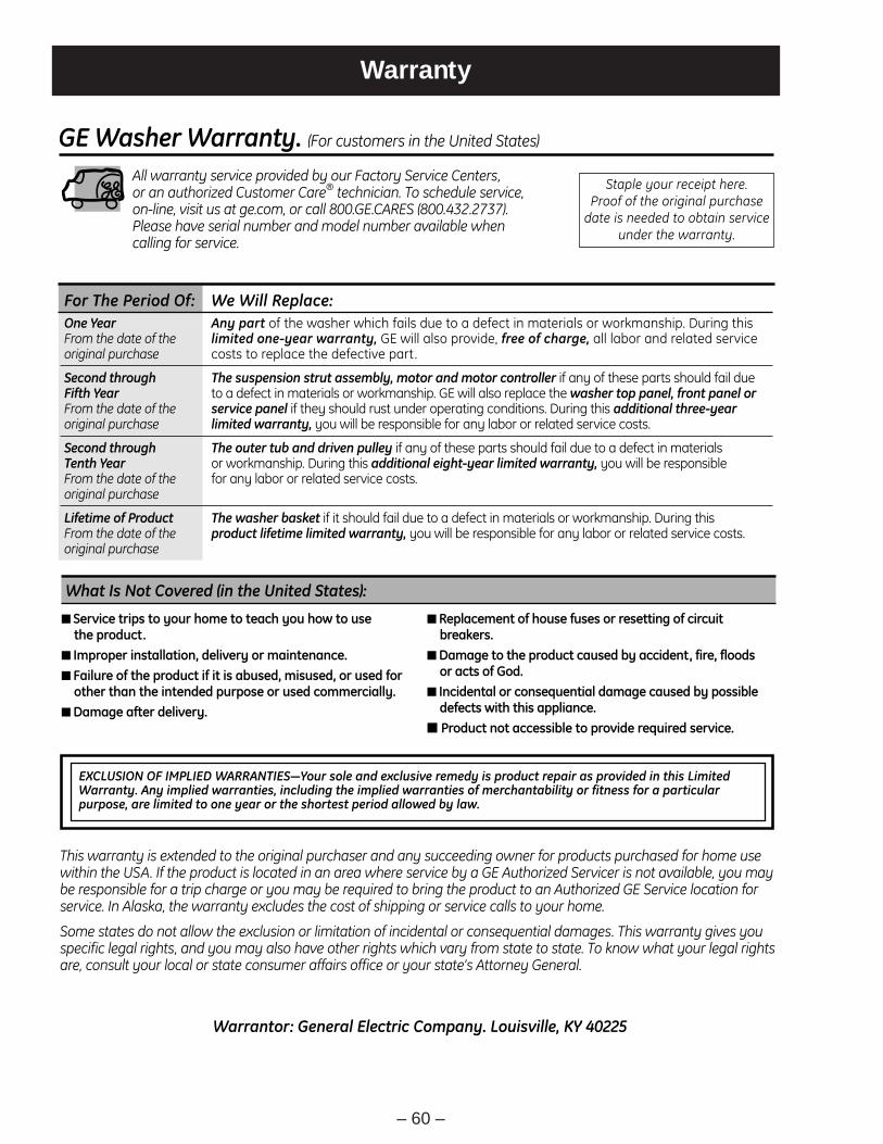
– 60 –
Warranty
For The Period Of: We Will Replace:
GE Washer Warranty. (For customers in the United States)
All warranty service provided by our Factory Service Centers, or an authorized Customer Care® technician. To schedule service,on-line, visit us at ge.com, or call 800.GE.CARES (800.432.2737).Please have serial number and model number available whencalling for service.
This warranty is extended to the original purchaser and any succeeding owner for products purchased for home usewithin the USA. If the product is located in an area where service by a GE Authorized Servicer is not available, you maybe responsible for a trip charge or you may be required to bring the product to an Authorized GE Service location forservice. In Alaska, the warranty excludes the cost of shipping or service calls to your home.
Some states do not allow the exclusion or limitation of incidental or consequential damages. This warranty gives youspecific legal rights, and you may also have other rights which vary from state to state. To know what your legal rightsare, consult your local or state consumer affairs office or your state’s Attorney General.
■ Service trips to your home to teach you how to use the product.
■ Improper installation, delivery or maintenance.■ Failure of the product if it is abused, misused, or used for
other than the intended purpose or used commercially.■ Damage after delivery.
■ Replacement of house fuses or resetting of circuitbreakers.
■ Damage to the product caused by accident, fire, floods or acts of God.
■ Incidental or consequential damage caused by possibledefects with this appliance.
■ Product not accessible to provide required service.
What Is Not Covered (in the United States):
Warrantor: General Electric Company. Louisville, KY 40225
Staple your receipt here. Proof of the original purchase
date is needed to obtain serviceunder the warranty.
One Year Any part of the washer which fails due to a defect in materials or workmanship. During thisFrom the date of the limited one-year warranty, GE will also provide, free of charge, all labor and related service original purchase costs to replace the defective part.
Second through The suspension strut assembly, motor and motor controller if any of these parts should fail due Fifth Year to a defect in materials or workmanship. GE will also replace the washer top panel, front panel or From the date of the service panel if they should rust under operating conditions. During this additional three-year original purchase limited warranty, you will be responsible for any labor or related service costs.
Second through The outer tub and driven pulley if any of these parts should fail due to a defect in materials Tenth Year or workmanship. During this additional eight-year limited warranty, you will be responsible From the date of the for any labor or related service costs.original purchase
Lifetime of Product The washer basket if it should fail due to a defect in materials or workmanship. During this From the date of the product lifetime limited warranty, you will be responsible for any labor or related service costs.original purchase
EXCLUSION OF IMPLIED WARRANTIES—Your sole and exclusive remedy is product repair as provided in this LimitedWarranty. Any implied warranties, including the implied warranties of merchantability or fitness for a particularpurpose, are limited to one year or the shortest period allowed by law.