Embed Size (px)
Citation preview
CUTOUT FOR SINGLE OVENS IN WALL CABINETNOTE: If the cabinet does not have a front frame and the sides are less than ¾” (1.9 cm) thick,shim both sides equally to establish the cutout width.
A2
BEFORE YOU BEGINRead these instructions completely andcarefully.
• IMPORTANT — Save theseinstructions for local inspector’s use.
• IMPORTANT — Observe allgoverning codes and ordinances.
• Note to Installer – Be sure to leave theseinstructions with Consumer.
• Note to Consumer – Keep theseinstructions for future reference.
• Skill level – Installation of this appliancerequires a qualified installer or electrician.
• Proper installation is the responsibility of the installer.
• Product failure due to improper installation is not covered under Warranty.
Installation Instructions
27" & 30" Electric Built-In Wall Ovens
31-10730-1 08-09 JR
FOR YOUR SAFETY:
WARNING: Before beginning the installation, switch power off at the servicepanel and lock the service disconnecting means to prevent power from being switched on accidentally.When the service disconnecting means cannot be locked, securely fasten a prominent warning device,such as a tag, to the service panel.
Be sure the oven is securely installed in a cabinet that is firmly attached to the house structure. Weight on the oven door could cause the oven to tip and result in injury. Never allow anyone to climb,sit, stand or hang on the oven door.
Make sure the wall coverings, counters and cabinets around the oven can withstand the heat (up to 200°F [93.3°C]) generated by the oven.
Questions? Call 1.800.GE.CARES (1.800.432.2737) or visit www.GEAppliances.com
In Canada, call 1.800.561.3344 or visit www.GEAppliances.ca
MATERIALS YOU MAY NEED
Junction Box
Wire Nuts
Strain Relief Clamp for 1/2" Conduit
36" (91 cm) of String
TOOLS YOU MAY NEED
1/8" Drill Bit and Electric or Hand Drill
Phillips Screwdriver
Wire Strippers
REMOVE PACKAGING MATERIALSFailure to remove packaging materials could result in damage to the appliance. Remove allpacking parts from oven, racks and heating elements. Remove protective film and labels on theouter door and control panel. Also, remove plastic on trims and panel, all tape around the ovenand any shipping screws securing the oven to the base pad. Open oven door and removeliterature pack and oven racks. Remove the bottom trim from the top of the oven. It will beinstalled at the end of the installation process. The trim is wrapped separately and taped to the top of the unit.
1
PREPARE THE OPENING (FOR INDOOR USE ONLY)NOTE: If the cabinet does not have a solid bottom,two braces or runners must be installed to supportthe weight of the oven. For single ovens, the runnersand braces must support 200 lbs (91 kg). For doubleovens, the runners and braces must support 375 lbs.(170 kg).
NOTE: If marks, blemishes or the cutout opening arevisible above the installed oven, it may be necessaryto add wood shims under the runners and front trimuntil the marks or opening are covered.
NOTE: If the cabinet does not have a front frameand the sides are less than ¾" (1.9 cm) thick, shimboth sides equally to establish the cutout width.
2
ATTENTION INSTALLER: All electric wall ovens must be hard-wired (direct-wired)into an approved junction box. A plug and receptacle is NOT permitted on these products.
These ovens are notapproved for stackableinstallations.
Cutout –observe alldimensions andrequirements.
Cutout –observe alldimensions andrequirements.
2" (5.1 cm) Min.
30.5" (77.5 cm)
Center Line Center Line
Side-by-Side Installations (30" only)Install two ovens in separate cutouts.
Dimension Dimension Description 27" Single Oven 30" Single Oven
A Cabinet Width 27" (68.6 cm) 30" (76.2 cm)
B Cutout Width 25" (63.5 cm) min. 281⁄2" (72.4 cm) min.251⁄4" (64.1 cm) max. 285⁄8" (72.7 cm) max.
C Cutout Height 275⁄8" (70.2 cm) min. 271⁄4" (69.2 cm) min.281⁄8" (71.4 cm) max. 275⁄16" (69.4 cm) max.
D Overlap of Oven Over 1" (2.5 cm) 11⁄16" (1.75 cm)Side Edges of Cutout
E Clearance to 20" (50.8 cm) min. 21" (53.3 cm) min.Adjacent Corners,
Drawers, Walls, etc.,When Door Is Open
F Overlap of Oven 1" (2.5 cm) min. 1" (2.5 cm) min.Top of Cutout
G Overlap of Oven 1" (2.5 cm) min. 11⁄4" (3.2 cm)Bottom of Cutout
H Junction Box Location 83⁄4" (22.2 cm) max. 91⁄2" (24.1 cm) max.right side only right side only
CUTOUT FOR DOUBLE OVENS (with Upper Microwave Oven)
NOTE: If the cabinet does not have a front frame and the sides are less than ¾" (1.9 cm) thick,shim both sides equally to establish the cutout width.
D2
Dimension 27" Oven 30" OvenDimension Description with Microwave with Microwave
A Cabinet Width 27" (68.6 cm) 30" (76.2 cm)
B Cutout Width 25" (63.5 cm) min. 281⁄2" (72.4 cm) min.251⁄4" (64.1 cm) max. 285⁄8" (72.7 cm) max.
C Cutout Height 411⁄8" (104.5 cm) min. 423⁄16" (107.2 cm) min.411⁄4" (104.8 cm) max. 421⁄4" (107.3 cm) max.
D Overlap of Oven 1" (2.5 cm) 11⁄16" (1.75 cm)Over Side Edges
of Cutout
E Clearance to Adjacent 20" (50.8 cm) min. 21" (53.3 cm)Corners, Drawers, Walls, etc., When Door Is Open
F Overlap of Oven 1" (2.5 cm) min. 1" (2.5 cm) min.Top of Cutout
G Overlap of Oven 1" (2.5 cm) min. 11⁄4" (3.2 cm)Bottom of Cutout
H Junction Box Location 83⁄4" (22.2 cm) max. 91⁄2" (24.1 cm) max.right side only right side only
Continue to Section 3.
Suitable Bracing to Support Runners
CL
21 5/8"(54.9 cm) Over
Centerline of Cabinet
2" x 4" (5 cm x 10 cm) or Equivalent Runners Level
with Bottom of Cutout
CUTOUT FOR SINGLE OVENS – UNDER COUNTERNOTE: These ovens are only approved to be installed under the specific models as labeled onthe unit.
B2
Dimension Dimension Description 27" Single Oven 30" Single Oven
A Cabinet Width 25" (63.5 cm) min. 281⁄2" (72.4 cm) min.251⁄4" (64.1 cm) max. 285⁄8" (72.7 cm) max.
B Cutout Height 275⁄8" (70.2 cm) min. 271⁄4" (69.2 cm) min.281⁄8" (71.4 cm) max. 275⁄16" (69.4 cm) max.
C Unit Overlap Top 1" (2.5 cm) 1" (2.5 cm)
D Unit Overlap Bottom 1" (2.5 cm) 11⁄4" (3.2 cm)
E Unit Overlap Side Edges 1" (2.5 cm) 11⁄16" (1.75 cm)
F Junction Box Location 83⁄4" (22.2 cm) max. 91⁄2" (24.1 cm) max.right side only right side only
Continue to Section 3.
NOTE: One cooktop may be centered over eitheroven in the side-by-side installation.
Cutout – observeall dimensions andrequirements.
2" (5.1 cm) Min.
30.5" (77.5 cm)
Center Line Center Line
Side-by-Side Installations (30" only)Install two ovens in separate cutouts.
Cooktop
Cutout – observeall dimensions andrequirements.
CUTOUT FOR INSTALLATION OVER A WARMINGDRAWER
NOTE: Install the oven only with specific models listed on the label located on top of the oven.
NOTE: Additional clearances between cutouts may be required. Check to be sure the ovensupports above the Warming Drawer location do not obstruct the required interior depth andheight.
When installing a Warming Drawer below a single or double oven, a separate 120V, 60 HZ,properly grounded receptacle must be installed. Refer to installation instructions packed with the Warming Drawer for specific installation requirements.
E2
Anti-Tip Block Against Rear Wall Per Warming Drawer Requirement
2" (5.1 cm) Min.
Per Warming Drawer Requirement
Continue to Section 3.
DESIGN INFORMATIONSINGLE OVEN INSTALLATIONS
The single oven may be installed in a cabinet alone or above a warming drawer. The single oven mayalso be installed below a countertop or below specified cooktops. See the label on top of the oven forapproved models.
DOUBLE OVEN INSTALLATIONS
A double oven may be installed in a cabinet alone or above a warming drawer. See the label on top ofthe oven for approved models.
IMPORTANT: Always refer to individual installation instructions packed with each product for specificrequirements.
CUTOUT FOR DOUBLE OVENS (2 Thermal Ovens)
NOTE: If the cabinet does not have a front frame and the sides are less than ¾” (1.9 cm) thick,shim both sides equally to establish the cutout width.
C2
Dimension Dimension Description 27" Double Oven 30" Double Oven
A Cabinet Width 27" (68.6 cm) 30" (76.2 cm)
B Cutout Width 25" (63.5 cm) min. 281⁄2" (72.4 cm) min.251⁄4" (64.1 cm) max. 285⁄8" (72.7 cm) max.
C Cutout Height 4911⁄16" (126.2 cm) min. 5113⁄16" (131.6 cm) min.501⁄8" (127.3 cm) max. 5115⁄16" (131.9 cm) max.
D Overlap of Oven 1" (2.5 cm) 11⁄16" (1.75 cm)Over Side Edges
of Cutout
E Clearance to Adjacent 20" (50.8 cm) min. 21" (53.3 cm) min.Corners, Drawers, Walls, etc., When Door Is Open
F Overlap of Oven 1" (2.5 cm) min. 1" (2.5 cm) min.Top of Cutout
G Overlap of Oven 1" (2.5 cm) min. 11⁄4" (3.2 cm)Bottom of Cutout
H Junction Box Location 83⁄4" (22.2 cm) max. 91⁄2" (24.1 cm) max.right side only right side only
J Height to Bottom of 44" (111.8 cm) 47" (119.4 cm)Junction Box
K Recommended 131⁄4" (33.7 cm) 12" (30.5 cm)Cutout Location from
Floor
Continue to Section 3.
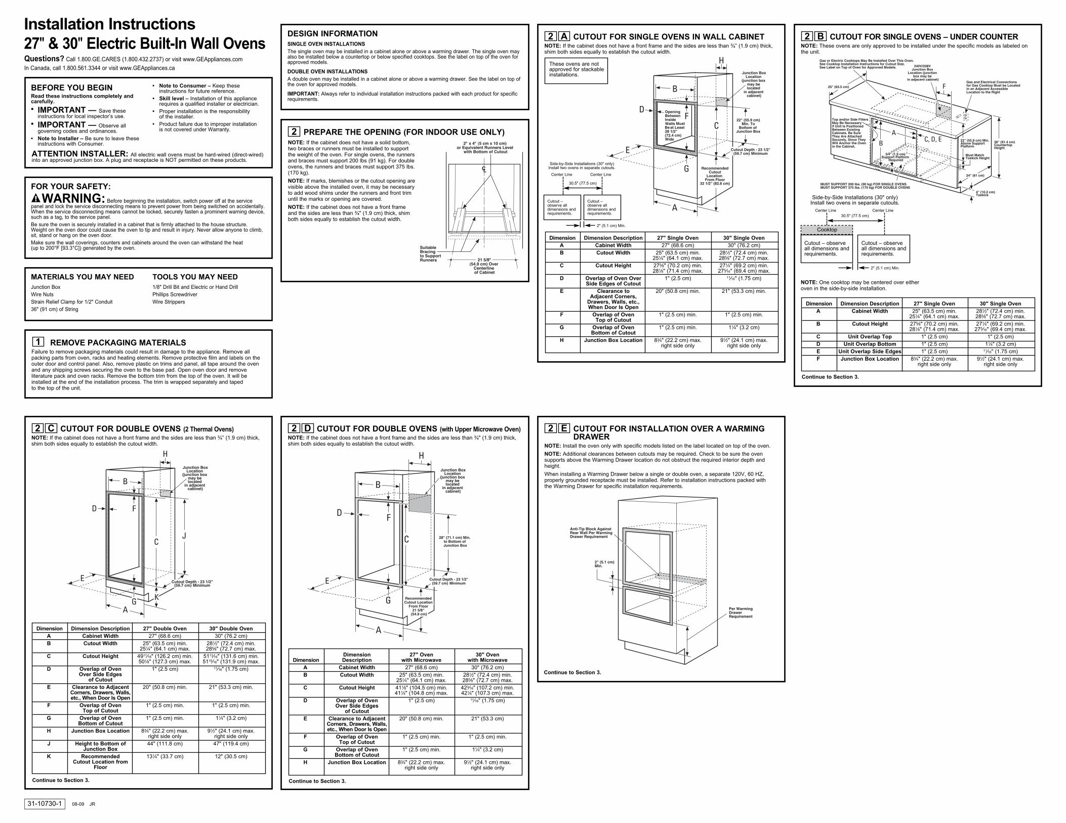
DOOR REMOVAL (recommended)NOTE: Door removal is not a requirement for installation of the product but is an addedconvenience.
To remove the door:
A. Open the oven door as far as it will go.
B. Push both hinge locks down toward the doorframe to the unlocked position. This may require aflat-blade screwdriver. DO NOT LIFT THE DOORBY THE HANDLE!
C. Place hands on both sides of the door and close the oven door to the removal position(approximately 1"–2" [2.5 cm–5.1 cm] from theclosed position).
D. Lift the door up and out until the hinge arms clearthe slots.NOTE: The oven door is very heavy. Be sure you have a firm grip before lifting the oven door offthe hinges. Use caution once the door is removed.Do not lay the door on its handle. This could cause dents or scratches.
3
ELECTRICAL REQUIREMENTS
WARNING: This appliance must be properly grounded.
WARNING: To prevent fire or shock, do not use an extension cord with thisappliance.
WARNING: To prevent shock, remove house fuse or open circuit breaker beforebeginning installation.
WARNING: Improper connection of aluminum house wiring to copper leads canresult in an electrical hazard or fire. Use only connectors designed for joining copper to aluminum andfollow the manufacturer’s recommended procedure closely.
We recommend you have the electrical wiring and hookup of your appliance connected by a qualified electrician. After installation, have the electrician show you how to disconnect power from the appliance.
You must use a single-phase, 120/208 VAC or 120/240 VAC, 60 Hertz electrical system. If youconnect to aluminum wiring, properly installed connectors approved for use with aluminum wiring mustbe used.
Effective January 1, 1996, the National Electrical Code requires that new construction (not existing)utilize a four-conductor connection to an electric oven. When installing an electric oven in newconstruction, a mobile home, recreational vehicle or an area where local codes prohibit groundingthrough the neutral conductor, refer to the section on four-conductor branch circuit connections.
Check with your local utilities for electrical codes which apply in your area. Failure to wire youroven according to governing codes could result in a hazardous condition. If there are no localcodes, your oven must be wired and fused to meet the National Electrical Code, NFPA No. 70 –latest edition, available from the National Fire Protection Association.
4
ELECTRICAL REQUIREMENTS (CONT.)This appliance must be supplied with the proper voltage and frequency and connected to an individual,properly grounded branch circuit, protected by a circuit breaker or fuse. See the rating plate located onthe oven frame to determine the rating of the product.
Use the chart below to determine the minimum recommended dedicated circuit protection:
DO NOT shorten the flexible conduit. The conduit strain relief clamp must be securely attached to the junction box and the flexible conduit must be securely attached to the clamp. If the flexibleconduit will not fit within the clamp, do not install the oven until a clamp of the proper size is obtained.
The 3 power leads supplied with this appliance are suitable for connection to heavier gauge householdwiring. The insulation of these 3 leads is rated for temperatures much higher than the temperaturerating of the household wiring. The current-carrying capacity of the conductor is governed by the wiregauge and the temperature rating of the insulation around the wire.
4
RecommendedKW Rating KW Rating Circuit Size
240V 208V (Dedicated)
≤4.8 KW ≤4.1 KW 20 Amp
4.9 KW–7.2 KW 4.2 KW–6.2 KW 30 Amp
7.3 KW–9.6 KW 6.3 KW–8.3 KW 40 Amp
9.7 KW–12.0 KW 8.4 KW–10.4 KW 50 Amp
Rating plate is located on the oven side trim, side front frame or lower front frame.
MOUNT THE OVEN
WARNING: Mounting screwsmust be used. Failure to do so could result in theoven falling out of the cabinet, causing serious injury.
NOTE: Before drilling the pilot holes, make surethe oven is pushed as far back into the openingas it will go and is centered.
NOTE: If the cabinet is particle board, you mustuse #8 x ¾" particle board screws. These may be purchased at any hardware store.
A. Drill through the mounting holes (top andbottom) of the side trim for the #8 mountingscrews provided.
B. Secure the oven cabinet with the screwsprovided.
9
Mounting Hole
Locations (hole locations
may vary)
BOTTOM TRIM INSTALLATIONA. With oven installed, take the bottom trim and
center it on the bottom front edge of the cabinetopening.
B. Using the trim as a template, mark the center of each slot (two total) where the mounting holeswill be drilled.
C. Remove the trim.
D. Drill pilot holes into the center of each templatemark.
E. Place the bottom metal trim centered over the predrilled mounting holes. Tape the edges of the trim down to maintain the alignment.
F. Using two trim screws provided, secure the bottomtrim to the bottom edge of the cabinet.
10
IMPORTANT: If this unit is ever removed fromthe cabinet or the oven is ever pulled out forservice, the bottom trim must be removed first or damage to the trim will occur.
REPLACING THE OVEN DOORNOTE: The oven door is heavy. You may need help lifting the door highenough to slide it into the hinge slots. Do not lift the door by the handle.
A. Lift the oven door by grasping each side.
B. With the door at the same angle as the removal position (approximately1"–2" [2.5 cm–5.1 cm] from the closed position), seat the notch of thehinge arm into the bottom edge of the hinge slot. The notch of the hingearm must be fully seated into the bottom of the slot.
C. Fully open the door. If the door will not fully open, the indentation is notseated correctly in the bottom edge of the slot.
D. Push the hinge locks up against the front frame of the oven cavity, to the locked position.
E. Close the oven door.
11
FINAL INSTALLATION CHECKLIST• Check to make sure the circuit breaker is closed (RESET) or the circuit fuses are replaced.
• Be sure power is in service to the building.
• Check that all packing material and tape have been removed. Failure to remove these materialscould result in damage to the appliance once the appliance has been turned on and surfaceshave heated.
• Remove all items from inside the oven.
• Check to be sure that the mounting screws are installed and flush with the side trim (see Section 9).
• Check that the bottom trim is installed properly (see Section 10).
OPERATION CHECKLIST• Turn on the power to the oven (refer to your Owner’s Manual). Verify that the bake and broil
units and all cooking functions operate properly.
• See your Owner’s Manual for the troubleshooting list.
• Be sure all of the oven controls are OFF before leaving the oven.
12
Hinge Slot
Hinge Arm
HingeUnlockedPosition
HingeClears Slot
The ScrewsMust Be aMinimum of1/4" (6 mm)From theFront of the Cutout.
For 27" (68.6 cm)Models withLower Trim inPosition, Mark (2)Mounting HoleLocations Here
Remove LowerTrim Before PredrillingMounting Holes
For 30" (76.2 cm)Models with LowerTrim in Position, Mark(2) Mounting HoleLocations Here
Trim ScrewLocations for 27"(68.6 cm) Modelswith Lower Trim
Side Trim
Metal Lower Trim
SideTrim
Trim Screw Locations for 30" (76.2 cm)Models with Lower Trim
Hinge inLockedPosition
Notch of HingeSecurely FittedInto Bottom ofHinge Slot
BottomEdge ofSlot
HingeArm
Hinge Notch
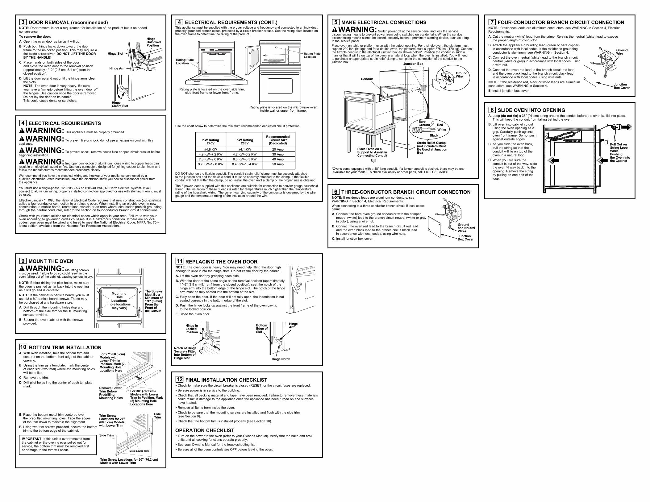
MAKE ELECTRICAL CONNECTIONS
WARNING: Switch power off at the service panel and lock the servicedisconnecting means to prevent power from being switched on accidentally. When the servicedisconnecting means cannot be locked, securely fasten a prominent warning device, such as a tag, to the service panel.
Place oven on table or platform even with the cutout opening. For a single oven, the platform mustsupport 200 lbs. (91 kg); and for a double oven, the platform must support 375 lbs. (170 kg). Connectthe flexible conduit to the electrical junction box as shown below*. Position the conduit in such amanner that it will lie on top of the oven in a natural loop when the oven is installed. You will need to purchase an appropriate strain relief clamp to complete the connection of the conduit to the junction box.
* Ovens come equipped with a 48" long conduit. If a longer conduit is desired, there may be oneavailable for your model. To check availability or order parts, call 1.800.GE.CARES.
5
THREE-CONDUCTOR BRANCH CIRCUIT CONNECTIONNOTE: If residence leads are aluminum conductors, seeWARNING in Section 4, Electrical Requirements.
When connecting to a three-conductor branch circuit, if local codespermit:
A. Connect the bare oven ground conductor with the crimpedneutral (white) lead to the branch circuit neutral (white or grayin color), using a wire nut.
B. Connect the oven red lead to the branch circuit red lead and the oven black lead to the branch circuit black lead in accordance with local codes, using wire nuts.
C. Install junction box cover.
6
Junction Box
Conduit
BareGround Red
White
Black
Strain Relief Clamp(not included) MustBe Used at JunctionBox
Place Oven on aSupport to Assist inConnecting Conduit
Groundand NeutralWires
JunctionBox Cover
GroundWire
FOUR-CONDUCTOR BRANCH CIRCUIT CONNECTIONNOTE: If residence leads are aluminum conductors, see WARNING in Section 4, ElectricalRequirements.
A. Cut the neutral (white) lead from the crimp. Re-strip the neutral (white) lead to expose the proper length of conductor.
B. Attach the appliance grounding lead (green or bare copper) in accordance with local codes. If the residence groundingconductor is aluminum, see WARNING in Section 4.
C. Connect the oven neutral (white) lead to the branch circuitneutral (white or gray) in accordance with local codes, using a wire nut.
D. Connect the oven red lead to the branch circuit red lead and the oven black lead to the branch circuit black lead in accordance with local codes, using wire nuts.
NOTE: If the residence red, black or white leads are aluminumconductors, see WARNING in Section 4.
E. Install junction box cover.
7
SLIDE OVEN INTO OPENINGA. Loop (do not tie) a 36” (91 cm) string around the conduit before the oven is slid into place.
This will keep the conduit from falling behind the oven.
B. Lift oven into cabinet cutoutusing the oven opening as agrip. Carefully push againstoven front frame. Do not pushagainst outside edges.
C. As you slide the oven back,pull the string so that theconduit will lie on top of theoven in a natural loop.
D. When you are sure theconduit is out of the way, slide the oven ¾ way back into theopening. Remove the string by pulling on one end of theloop.
8
�
GroundWire
JunctionBox Cover
Pull Out onString LoopWhilePushing the Oven Intothe Cabinet
Rating plate is located on the microwave oveninside wall or upper front frame.
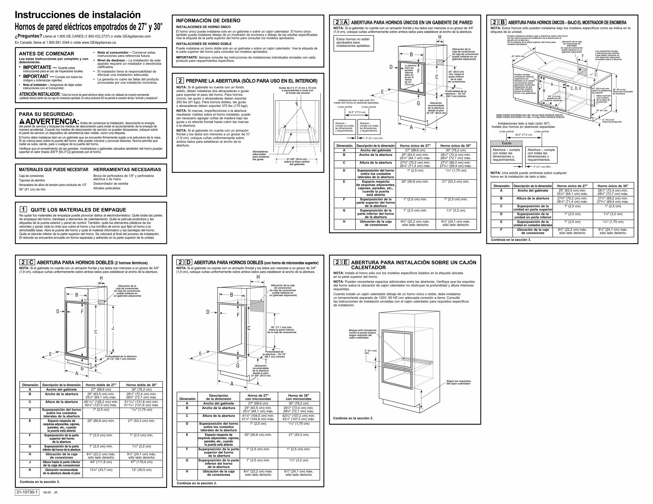
ABERTURA PARA HORNOS ÚNICOS EN UN GABIENTE DE PAREDNOTA: Si el gabinete no cuenta con un armazón frontal y los lados son menores a un grosor de 3/4”(1,9 cm), coloque cuñas uniformemente sobre ambos lados para establecer al ancho de la abertura.
A2
ANTES DE COMENZARLea estas instrucciones por completo y condetenimiento.
• IMPORTANTE — Guarde estasinstrucciones para el uso de inspectores locales.
• IMPORTANT — Cumpla con todos loscódigos y ordenanzas vigentes.
• Nota al instalador – Asegúrese de dejar estasinstrucciones con el Consumidor.
• Nota al consumidor – Conserve estasinstrucciones para referencia futura.
• Nivel de destreza – La instalación de esteaparato requiere un instalador o electricistacalificados.
• El instalador tiene la responsabilidad deefectuar una instalación adecuada.
• La garantía no cubre las fallas del productoprovocadas por una instalación incorrecta.
Instrucciones de instalaciónHornos de pared eléctricos empotrados de 27" y 30"
31-10730-1 08-09 JR
PARA SU SEGURIDAD:
ADVERTENCIA: Antes de comenzar la instalación, desconecte la energía del panel de servicio y bloquee los medios de desconexión para evitar el accionamiento de la energía demanera accidental. Cuando los medios de desconexión de servicio no pueden bloquearse, coloque sobre el panel de servicio un dispositivo de advertencia bien visible, como una etiqueta.El horno debe instalarse bien en un gabinete que se encuentre firmemente sujeto a la estructura de la casa.Si se coloca peso sobre la puerta del horno, éste puede volcarse y provocar lesiones. Nunca permita quenadie se suba, siente, pare o cuelgue de la puerta del horno. Verifique que el revestimiento de las paredes, mostradores y gabinetes ubicados alrededor del horno puedansoportar el calor (hasta 200°F [93,3°C]) generado por el horno.
¿Preguntas? Llame al 1.800.GE.CARES (1.800.432.2737) o visite GEAppliances.com
En Canadá, llame al 1.800.561.3344 o visite www.GEAppliances.ca.
MATERIALES QUE PUEDE NECESITARCaja de conexionesTapones de alambreAbrazadera de alivio de tensión para conducto de 1/2"36" (91 cm) de hilo
HERRAMIENTAS NECESARIASBroca de perforadora de 1/8" y perforadoraeléctrica o de manoDestornillador de estrellaAlicates pelacables
QUITE LOS MATERIALES DE EMPAQUENo quitar los materiales de empaque puede provocar daños al electrodoméstico. Quite todas las partesde empaque del horno, bandejas y elementos de calentamiento. Quite la película protectora y lasetiquetas de la puerta exterior y panel de control. También, quite los elementos plásticos de losrebordes y panel, toda la cinta que cubre el horno y los tornillos de envío que fijan el horno a laalmohadilla base. Abra la puerta del horno y quite el material informativo y las bandejas del horno.Quite el reborde inferior de la parte superior del horno. Se colocará al final del proceso de instalación.El reborde se encuentra envuelto en forma separada y adherido en la parte superior de la unidad.
1
PREPARE LA ABERTURA (SÓLO PARA USO EN EL INTERIOR)NOTA: Si el gabinete no cuenta con un fondosólido, deben instalarse dos abrazaderas o guíaspara soportar el peso del horno. Para hornosúnicos, las guías o abrazaderas deben soportar200 lbs (91 kgs). Para hornos dobles, las guías o abrazaderas deben soportar 375 lbs (170 kgs).
NOTA: Si marcas, imperfecciones o la aberturaresultaran visibles sobre el horno instalado, puedeser necesario agregar cuñas de madera bajo lasguías y el reborde frontal hasta cubrir las marcas o la abertura.
NOTA: Si el gabinete no cuenta con un armazónfrontal y los lados son menores a un grosor de ¾"(1,9 cm), coloque cuñas uniformemente sobreambos lados para establecer al ancho de laabertura.
2
ATENCIÓN INSTALADOR: Todos los hornos de pared eléctricos deben contar con cableado de conexión permanente (cableado directo) dentro de una caja de conexiones aprobada. En estos productos NO se permite la conexión del tipo “enchufe y receptáculo”.
Estos hornos no estánaprobados parainstalaciones apilables.
Abertura –cumpla con todaslas dimensionesy requerimientos.
Abertura –cumpla con todaslas dimensionesy requerimientos.
2" (5,1 cm) mín.
30.5" (77,5 cm)
Línea central Línea central
Instalaciones lado a lado (sólo 30")Instale dos hornos en aberturas separadas.
Dimensión Descripción de la dimensión Horno único de 27" Horno único de 30"A Ancho del gabinete 27" (68,6 cm) 30" (76,2 cm)B Ancho de la abertura 25" (63,5 cm) mín. 281⁄2" (72,4 cm) mín.
251⁄4" (64,1 cm) máx. 285⁄8" (72,7 cm) máx.C Altura de la abertura 275⁄8" (70,2 cm) mín. 271⁄4" (69,2 cm) mín.
281⁄8" (71,4 cm) máx. 275⁄16" (69,4 cm) máx.D Superposición del horno 1" (2,5 cm) 11⁄16" (1,75 cm)
sobre los costados laterales de la abertura
E Espacio respecto 20" (50,8 cm) mín. 21" (53,3 cm) mín.de esquinas adyacentes, cajones, paredes, etc.,
cuando la puerta está abierta
F Superposición de la 1" (2,5 cm) mín. 1" (2,5 cm) mín.parte superior del horno
de la abertura G Superposición de la 1" (2,5 cm) mín. 11⁄4" (3,2 cm)
parte inferior del horno de la abertura
H Ubicación de la caja 83⁄4" (22,2 cm) máx. 91⁄2" (24,1 cm) máx.de conexiones sólo lado derecho sólo lado derecho
ABERTURA PARA HORNOS DOBLES (con horno de microondas superior)NOTA: Si el gabinete no cuenta con un armazón frontal y los lados son menores a un grosor de 3/4"(1,9 cm), coloque cuñas uniformemente sobre ambos lados para establecer al ancho de la abertura.
D2
Descripción Horno de 27" Horno de 30" Dimensión de la dimensión con microondas con microondas
A Ancho del gabinete 27" (68,6 cm) 30" (76,2 cm)B Ancho de la abertura 25" (63,5 cm) mín. 281⁄2" (72,4 cm) mín.
251⁄4" (64,1 cm) máx. 285⁄8" (72,7 cm) máx.C Altura de la abertura 411⁄8" (104,5 cm) mín. 423⁄16" (107,2 cm) mín.
411⁄4" (104,8 cm) máx. 421⁄4" (107,3 cm) máx.D Superposición del horno 1" (2,5 cm) 11⁄16" (1,75 cm)
sobre los costados laterales de la abertura
E Espacio respecto de 20" (50,8 cm) mín. 21" (53,3 cm)esquinas adyacentes, cajones,
paredes, etc., cuando la puerta está abierta
F Superposición de la parte 1" (2,5 cm) mín. 1" (2,5 cm) mín.superior del horno
de la aberturaG Superposición de la parte 1" (2,5 cm) mín. 11⁄4" (3,2 cm)
inferior del horno de la abertura
H Ubicación de la caja 83⁄4" (22,2 cm) máx. 91⁄2" (24,1 cm) máx.de conexiones sólo lado derecho sólo lado derecho
Continúe en la sección 3.
ABERTURA PARA HORNOS ÚNICOS – BAJO EL MOSTRADOR DE ENCIMERANOTA: Estos hornos sólo pueden instalarse bajo los modelos específicos como se indica en laetiqueta de la unidad.
B2
Dimensión Descripción de la dimensión Horno único de 27" Horno único de 30" A Ancho del gabinete 25" (63,5 cm) mín. 281⁄2" (72,4 cm) mín.
251⁄4" (64,1 cm) máx. 285⁄8" (72,7 cm) máx.B Altura de la abertura 275⁄8" (70,2 cm) mín. 271⁄4" (69,2 cm) mín.
281⁄8" (71,4 cm) máx. 275⁄16" (69,4 cm) máx.C Superposición de la 1" (2,5 cm) 1" (2,5 cm)
unidad en parte superiorD Superposición de la 1" (2,5 cm) 11⁄4" (3,2 cm)
unidad en parte inferiorE Superposición de la 1" (2,5 cm) 11⁄16" (1,75 cm)
unidad en costados lateralesF Ubicación de la caja 83⁄4" (22,2 cm) máx. 91⁄2" (24,1 cm) máx.
de conexiones sólo lado derecho sólo lado derecho
Continúe en la sección 3.
NOTA: Una estufa puede centrarse sobre cualquierhorno en la instalación de lado a lado.
Abertura – cumplacon todas lasdimensiones yrequerimientos.
2" (5,1 cm) Mín.
30,5" (77,5 cm)Línea central Línea central
Instalaciones lado a lado (sólo 30")Instale dos hornos en aberturas separadas.
Estufa
Abertura – cumplacon todas lasdimensiones yrequerimientos.
ABERTURA PARA INSTALACIÓN SOBRE UN CAJÓNCALENTADOR
NOTA: Instale el horno sólo con los modelos específicos listados en la etiqueta ubicada en la parte superior del horno.
NOTA: Pueden necesitarse espacios adicionales entre las aberturas. Verifique que los soportesdel horno sobre la ubicación de cajón calentador no obstruyan la profundidad y altura interioresrequeridas.
Cuando instale un cajón calentador debajo de un horno único o doble, debe instalarse un tomacorriente separado de 120V, 60 HZ con adecuada conexión a tierra. Consulte las instrucciones de instalación enviadas con el cajón calentador para requisitos específicos de instalación.
E2
Continúe en la sección 3.
INFORMACIÓN DE DISEÑOINSTALACIONES DE HORNO ÚNICOEl horno único puede instalarse solo en un gabinete o sobre un cajón calentador. El horno únicotambién puede instalarse debajo de un mostrador de encimera o debajo de las estufas especificadas.Vea la etiqueta de la parte superior del horno para consultar los modelos aprobados.
INSTALACIONES DE HORNO DOBLEPuede instalarse un horno doble solo en un gabinete o sobre un cajón calentador. Vea la etiqueta dela parte superior del horno para consultar los modelos aprobados.
IMPORTANTE: Siempre consulte las instrucciones de instalaciones individuales enviadas con cadaproducto para requerimientos específicos.
ABERTURA PARA HORNOS DOBLES (2 hornos térmicos)NOTA: Si el gabinete no cuenta con un armazón frontal y los lados son menores a un grosor de 3/4"(1,9 cm), coloque cuñas uniformemente sobre ambos lados para establecer al ancho de la abertura.
C2
Dimensión Descripción de la dimensión Horno doble de 27" Horno doble de 30"A Ancho del gabinete 27" (68,6 cm) 30" (76,2 cm)B Ancho de la abertura 25" (63,5 cm) mín. 281⁄2" (72,4 cm) mín.
251⁄4" (64,1 cm) máx. 285⁄8" (72,7 cm) máx.C Altura de la abertura 4911⁄16" (126,2 cm) mín. 5113⁄16" (131,6 cm) mín.
501⁄8" (127,3 cm) máx. 5115⁄16" (131,9 cm) máx.D Superposición del horno 1" (2,5 cm) 11⁄16" (1,75 cm)
sobre los costados laterales de la abertura
E Espacio respecto de 20" (50,8 cm) mín. 21" (53,3 cm) mín.esquinas adyacentes, cajones,
paredes, etc., cuando la puerta está abierta
F Superposición de la parte 1" (2,5 cm) mín. 1" (2,5 cm) mín.superior del horno
de la aberturaG Superposición de la parte 1" (2,5 cm) mín. 11⁄4" (3,2 cm)
inferior del horno de la aberturaH Ubicación de la caja 83⁄4" (22,2 cm) máx. 91⁄2" (24,1 cm) máx.
de conexiones sólo lado derecho sólo lado derechoJ Altura hasta la parte inferior 44" (111,8 cm) 47" (119,4 cm)
de la caja de conexionesK Ubicación recomendada 131⁄4" (33,7 cm) 12" (30,5 cm)
de la abertura desde el piso
Continúe en la sección 3.
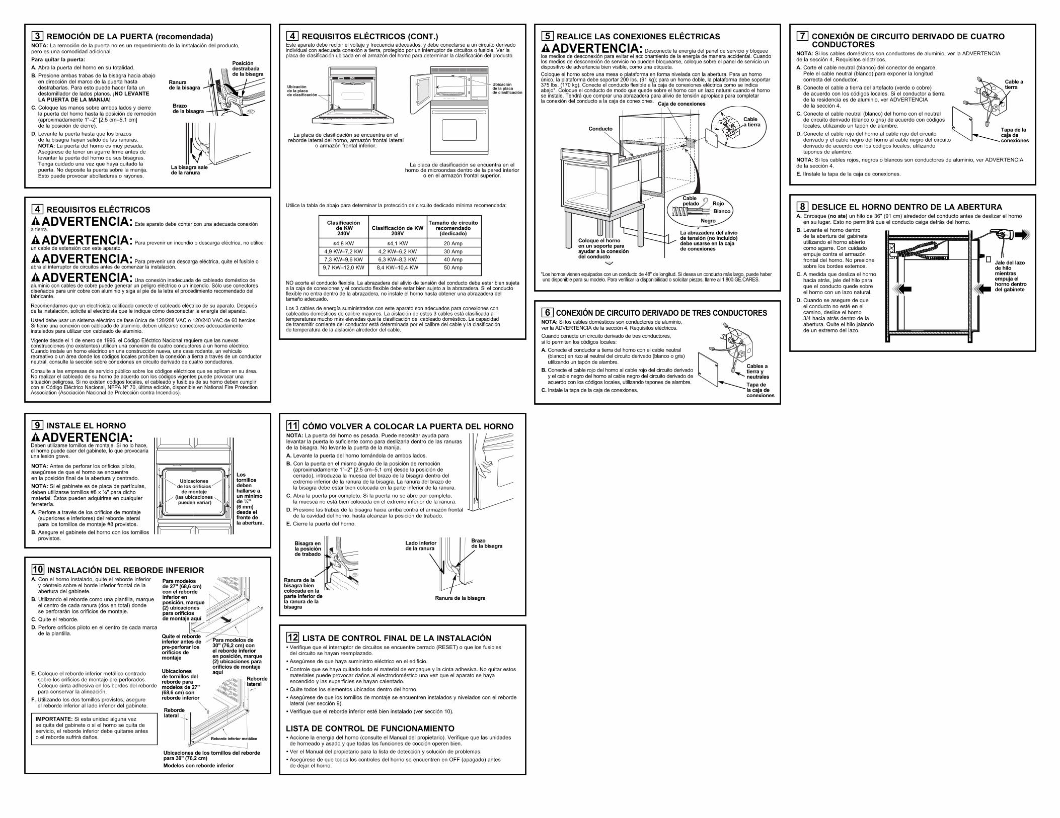
REMOCIÓN DE LA PUERTA (recomendada)NOTA: La remoción de la puerta no es un requerimiento de la instalación del producto, pero es una comodidad adicional.
Para quitar la puerta:
A. Abra la puerta del horno en su totalidad.
B. Presione ambas trabas de la bisagra hacia abajoen dirección del marco de la puerta hastadestrabarlas. Para esto puede hacer falta undestornillador de lados planos. ¡NO LEVANTE LA PUERTA DE LA MANIJA!
C. Coloque las manos sobre ambos lados y cierre la puerta del horno hasta la posición de remoción(aproximadamente 1"–2" [2,5 cm–5,1 cm] de la posición de cierre).
D. Levante la puerta hasta que los brazos de la bisagra hayan salido de las ranuras. NOTA: La puerta del horno es muy pesada.Asegúrese de tener un agarre firme antes delevantar la puerta del horno de sus bisagras.Tenga cuidado una vez que haya quitado lapuerta. No deposite la puerta sobre la manija.Esto puede provocar abolladuras o rayones.
3
REQUISITOS ELÉCTRICOS
ADVERTENCIA: Este aparato debe contar con una adecuada conexión a tierra.
ADVERTENCIA: Para prevenir un incendio o descarga eléctrica, no utiliceun cable de extensión con este aparato.
ADVERTENCIA: Para prevenir una descarga eléctrica, quite el fusible oabra el interruptor de circuitos antes de comenzar la instalación.
ADVERTENCIA: Una conexión inadecuada de cableado doméstico dealuminio con cables de cobre puede generar un peligro eléctrico o un incendio. Sólo use conectoresdiseñados para unir cobre con aluminio y siga al pie de la letra el procedimiento recomendado delfabricante.
Recomendamos que un electricista calificado conecte el cableado eléctrico de su aparato. Después de la instalación, solicite al electricista que le indique cómo desconectar la energía del aparato.
Usted debe usar un sistema eléctrico de fase única de 120/208 VAC o 120/240 VAC de 60 hercios. Si tiene una conexión con cableado de aluminio, deben utilizarse conectores adecuadamenteinstalados para utilizar con cableado de aluminio.
Vigente desde el 1 de enero de 1996, el Código Eléctrico Nacional requiere que las nuevasconstrucciones (no existentes) utilicen una conexión de cuatro conductores a un horno eléctrico.Cuando instale un horno eléctrico en una construcción nueva, una casa rodante, un vehículorecreativo o un área donde los códigos locales prohíben la conexión a tierra a través de un conductorneutral, consulte la sección sobre conexiones en circuito derivado de cuatro conductores.
Consulte a las empresas de servicio público sobre los códigos eléctricos que se aplican en su área.No realizar el cableado de su horno de acuerdo con los códigos vigentes puede provocar unasituación peligrosa. Si no existen códigos locales, el cableado y fusibles de su horno deben cumplircon el Código Eléctrico Nacional, NFPA Nº 70, última edición, disponible en National Fire ProtectionAssociation (Asociación Nacional de Protección contra Incendios).
4
REQUISITOS ELÉCTRICOS (CONT.)Este aparato debe recibir el voltaje y frecuencia adecuados, y debe conectarse a un circuito derivadoindividual con adecuada conexión a tierra, protegido por un interruptor de circuitos o fusible. Ver laplaca de clasificación ubicada en el armazón del horno para determinar la clasificación del producto.
Utilice la tabla de abajo para determinar la protección de circuito dedicado mínima recomendada:
NO acorte el conducto flexible. La abrazadera del alivio de tensión del conducto debe estar bien sujetaa la caja de conexiones y el conducto flexible debe estar bien sujeto a la abrazadera. Si el conductoflexible no entra dentro de la abrazadera, no instale el horno hasta obtener una abrazadera deltamaño adecuado.
Los 3 cables de energía suministrados con este aparato son adecuados para conexiones concableados domésticos de calibre mayores. La aislación de estos 3 cables está clasificada atemperaturas mucho más elevadas que la clasificación del cableado doméstico. La capacidad de transmitir corriente del conductor está determinada por el calibre del cable y la clasificación de temperatura de la aislación alrededor del cable.
4
Clasificación Tamaño de circuitode KW Clasificación de KW recomendado 240V 208V (dedicado)
≤4,8 KW ≤4,1 KW 20 Amp
4,9 KW–7,2 KW 4,2 KW–6,2 KW 30 Amp
7,3 KW–9,6 KW 6,3 KW–8,3 KW 40 Amp
9,7 KW–12,0 KW 8,4 KW–10,4 KW 50 Amp
La placa de clasificación se encuentra en elreborde lateral del horno, armazón frontal lateral
o armazón frontal inferior.
INSTALE EL HORNO
ADVERTENCIA:Deben utilizarse tornillos de montaje. Si no lo hace,el horno puede caer del gabinete, lo que provocaríauna lesión grave.
NOTA: Antes de perforar los orificios piloto,asegúrese de que el horno se encuentre en la posición final de la abertura y centrado.
NOTA: Si el gabinete es de placa de partículas,deben utilizarse tornillos #8 x ¾" para dichomaterial. Éstos pueden adquirirse en cualquierferretería.
A. Perfore a través de los orificios de montaje(superiores e inferiores) del reborde lateralpara los tornillos de montaje #8 provistos.
B. Asegure el gabinete del horno con los tornillosprovistos.
9
INSTALACIÓN DEL REBORDE INFERIORA. Con el horno instalado, quite el reborde inferior
y céntrelo sobre el borde inferior frontal de laabertura del gabinete.
B. Utilizando el reborde como una plantilla, marque el centro de cada ranura (dos en total) donde se perforarán los orificios de montaje.
C. Quite el reborde.
D. Perfore orificios piloto en el centro de cada marcade la plantilla.
E. Coloque el reborde inferior metálico centradosobre los orificios de montaje pre-perforados.Coloque cinta adhesiva en los bordes del rebordepara conservar la alineación.
F. Utilizando los dos tornillos provistos, asegure el reborde inferior al lado inferior del gabinete.
10
IMPORTANTE: Si esta unidad alguna vez se quita del gabinete o si el horno se quita deservicio, el reborde inferior debe quitarse antes o el reborde sufrirá daños.
CÓMO VOLVER A COLOCAR LA PUERTA DEL HORNONOTA: La puerta del horno es pesada. Puede necesitar ayuda paralevantar la puerta lo suficiente como para deslizarla dentro de las ranurasde la bisagra. No levante la puerta de la manija.
A. Levante la puerta del horno tomándola de ambos lados.
B. Con la puerta en el mismo ángulo de la posición de remoción(aproximadamente 1"–2" [2,5 cm–5,1 cm] desde la posición decerrado), introduzca la muesca del brazo de la bisagra dentro delextremo inferior de la ranura de la bisagra. La ranura del brazo de la bisagra debe estar bien colocada en la parte inferior de la ranura.
C. Abra la puerta por completo. Si la puerta no se abre por completo, la muesca no está bien colocada en el extremo inferior de la ranura.
D. Presione las trabas de la bisagra hacia arriba contra el armazón frontalde la cavidad del horno, hasta alcanzar la posición de trabado.
E. Cierre la puerta del horno.
11
LISTA DE CONTROL FINAL DE LA INSTALACIÓN • Verifique que el interruptor de circuitos se encuentre cerrado (RESET) o que los fusibles
del circuito se hayan reemplazado.
• Asegúrese de que haya suministro eléctrico en el edificio.
• Controle que se haya quitado todo el material de empaque y la cinta adhesiva. No quitar estosmateriales puede provocar daños al electrodoméstico una vez que el aparato se hayaencendido y las superficies se hayan calentado.
• Quite todos los elementos ubicados dentro del horno.
• Asegúrese de que los tornillos de montaje se encuentren instalados y nivelados con el rebordelateral (ver sección 9).
• Verifique que el reborde inferior esté bien instalado (ver sección 10).
LISTA DE CONTROL DE FUNCIONAMIENTO• Accione la energía del horno (consulte el Manual del propietario). Verifique que las unidades
de horneado y asado y que todas las funciones de cocción operen bien.
• Ver el Manual del propietario para la lista de detección y solución de problemas.
• Asegúrese de que todos los controles del horno se encuentren en OFF (apagado) antes de dejar el horno.
12
Ranura de la bisagra
Brazo de la bisagra
Posicióndestrabadade la bisagra
La bisagra salede la ranura
Lostornillosdebenhallarse aun mínimode ¼" (6 mm)desde elfrente de la abertura.
Para modelos de 27" (68,6 cm)con el rebordeinferior enposición, marque(2) ubicacionespara orificios de montaje aquí
Quite el rebordeinferior antes depre-perforar losorificios demontaje
Para modelos de 30" (76,2 cm) con el reborde inferior en posición, marque(2) ubicaciones paraorificios de montajeaquíUbicaciones
de tornillos delreborde paramodelos de 27"(68,6 cm) conreborde inferior
Rebordelateral
Reborde inferior metálico
Rebordelateral
Ubicaciones de los tornillos del rebordepara 30" (76,2 cm)Modelos con reborde inferior
Bisagra enla posiciónde trabado
Ranura de labisagra biencolocada en laparte inferior dela ranura de labisagra
Lado inferiorde la ranura
Brazo de la bisagra
Ranura de la bisagra
REALICE LAS CONEXIONES ELÉCTRICAS
ADVERTENCIA: Desconecte la energía del panel de servicio y bloqueelos medios de desconexión para evitar el accionamiento de la energía de manera accidental. Cuandolos medios de desconexión de servicio no pueden bloquearse, coloque sobre el panel de servicio undispositivo de advertencia bien visible, como una etiqueta.Coloque el horno sobre una mesa o plataforma en forma nivelada con la abertura. Para un hornoúnico, la plataforma debe soportar 200 lbs. (91 kg); para un horno doble, la plataforma debe soportar375 lbs. (170 kg). Conecte el conducto flexible a la caja de conexiones eléctrica como se indicaabajo*. Coloque el conducto de modo que quede sobre el horno con un lazo natural cuando el hornose instale. Tendrá que comprar una abrazadera para alivio de tensión apropiada para completar la conexión del conducto a la caja de conexiones.
* Los hornos vienen equipados con un conducto de 48" de longitud. Si desea un conducto más largo, puede haberuno disponible para su modelo. Para verificar la disponibilidad o solicitar piezas, llame al 1.800.GE.CARES.
5
CONEXIÓN DE CIRCUITO DERIVADO DE TRES CONDUCTORESNOTA: Si los cables domésticos son conductores de aluminio, ver la ADVERTENCIA de la sección 4, Requisitos eléctricos.
Cuando conecte un circuito derivado de tres conductores, si lo permiten los códigos locales:
A. Conecte el conductor a tierra del horno con el cable neutral(blanco) en rizo al neutral del circuito derivado (blanco o gris)utilizando un tapón de alambre.
B. Conecte el cable rojo del horno al cable rojo del circuito derivadoy el cable negro del horno al cable negro del circuito derivado deacuerdo con los códigos locales, utilizando tapones de alambre.
C. Instale la tapa de la caja de conexiones.
6
Caja de conexiones
Conducto
Cablepelado Rojo
Blanco
Negro
La abrazadera del aliviode tensión (no incluido)debe usarse en la cajade conexiones
Coloque el horno en un soporte paraayudar a la conexióndel conducto
Cables atierra yneutrales
Tapa de la caja deconexiones
Cable a tierra
CONEXIÓN DE CIRCUITO DERIVADO DE CUATROCONDUCTORES
NOTA: Si los cables domésticos son conductores de aluminio, ver la ADVERTENCIA de la sección 4, Requisitos eléctricos.
A. Corte el cable neutral (blanco) del conector de engarce. Pele el cable neutral (blanco) para exponer la longitudcorrecta del conductor.
B. Conecte el cable a tierra del artefacto (verde o cobre) de acuerdo con los códigos locales. Si el conductor a tierrade la residencia es de aluminio, ver ADVERTENCIA de la sección 4.
C. Conecte el cable neutral (blanco) del horno con el neutral de circuito derivado (blanco o gris) de acuerdo con códigoslocales, utilizando un tapón de alambre.
D. Conecte el cable rojo del horno al cable rojo del circuitoderivado y el cable negro del horno al cable negro del circuitoderivado de acuerdo con los códigos locales, utilizandotapones de alambre.
NOTA: Si los cables rojos, negros o blancos son conductores de aluminio, ver ADVERTENCIAde la sección 4.
E. IInstale la tapa de la caja de conexiones.
7
DESLICE EL HORNO DENTRO DE LA ABERTURAA. Enrosque (no ate) un hilo de 36" (91 cm) alrededor del conducto antes de deslizar el horno
en su lugar. Esto no permitirá que el conducto caiga detrás del horno.
B. Levante el horno dentro de la abertura del gabineteutilizando el horno abiertocomo agarre. Con cuidadoempuje contra el armazónfrontal del horno. No presionesobre los bordes externos.
C. A medida que desliza el hornohacia atrás, jale del hilo paraque el conducto quede sobreel horno con un lazo natural.
D. Cuando se asegure de que el conducto no esté en elcamino, deslice el horno 3/4 hacia atrás dentro de laabertura. Quite el hilo jalandode un extremo del lazo.
8
�
Cable atierra
Tapa de lacaja deconexiones
Jale del lazode hilomientrasempuja elhorno dentrodel gabinete
La placa de clasificación se encuentra en elhorno de microondas dentro de la pared interior
o en el armazón frontal superior.