Embed Size (px)
Citation preview
PRO-DIA
LOG +
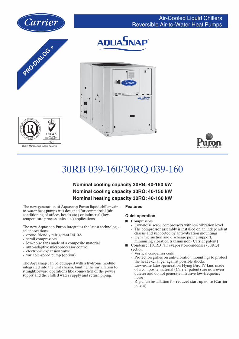
Air-Cooled Liquid ChillersReversible Air-to-Water Heat Pumps
30RB 039-160/30RQ 039-160Nominal cooling capacity 30RB: 40-160 kWNominal cooling capacity 30RQ: 40-150 kWNominal heating capacity 30RQ: 40-160 kW
The new generation of Aquasnap Puron liquid chillers/air-to-water heat pumps was designed for commercial (air conditioning of offices, hotels etc.) or industrial (low-temperature process units etc.) applications.
The new Aquasnap Puron integrates the latest technologi-cal innovations:
ozone-friendly refrigerant R410Ascroll compressorslow-noise fans made of a composite materialauto-adaptive microprocessor controlelectronic expansion valvevariable-speed pump (option)
The Aquasnap can be equipped with a hydronic module integrated into the unit chassis, limiting the installation to straightforward operations like connection of the power supply and the chilled water supply and return piping.
------
Features
Quiet operationCompressors
Low-noise scroll compressors with low vibration levelThe compressor assembly is installed on an independent chassis and supported by anti-vibration mountingsDynamic suction and discharge piping support, minimising vibration transmission (Carrier patent)
Condenser (30RB)/air evaporator/condenser (30RQ) section
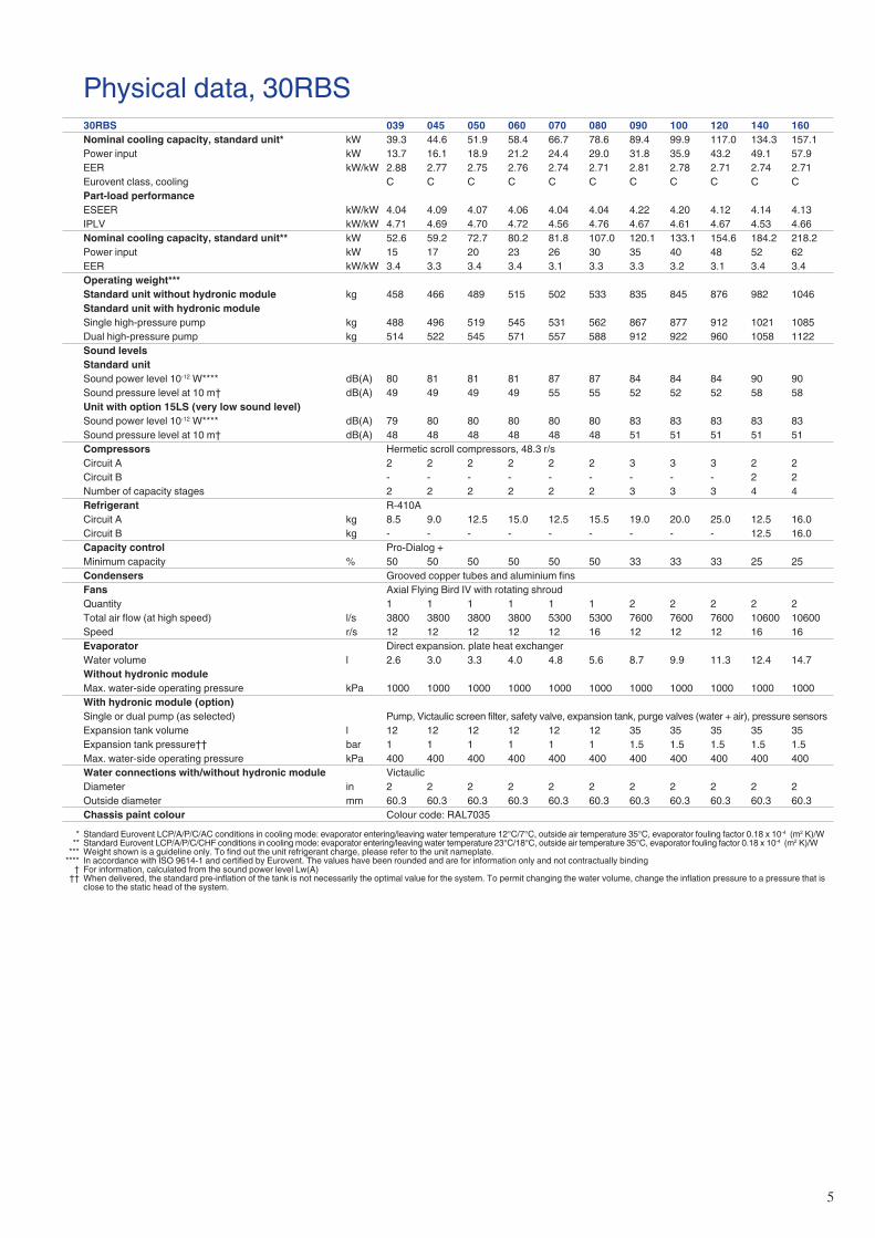
Vertical condenser coilsProtection grilles on anti-vibration mountings to protect the heat exchanger against possible shocks.Low-noise latest-generation Flying Bird IV fans, made of a composite material (Carrier patent) are now even quieter and do not generate intrusive low-frequency noiseRigid fan installation for reduced start-up noise (Carrier patent)
■
--
-
■
--
-
-
�
Reduced maintenance costsMaintenance-free scroll compressorsFast diagnosis of possible incidents and their history via the Pro-Dialog+ controlR410A refrigerant is easier to use than other refrigerant blends
Environmental careOzone-friendly R410A refrigerant
Chlorine-free refrigerant of the HFC group with zero ozone depletion potentialHigh-density refrigerant, therefore less refrigerant requiredVery efficient - gives an increased energy efficiency ratio (EER, COP and ESEER)
Leak-tight refrigerant circuitBrazed refrigerant connections for increased leak-tightnessReduction of leaks due to reduced vibration levels and elimination of capillary tubes (TXVs)Verification of pressure transducers and temperature sensors without transferring refrigerant charge
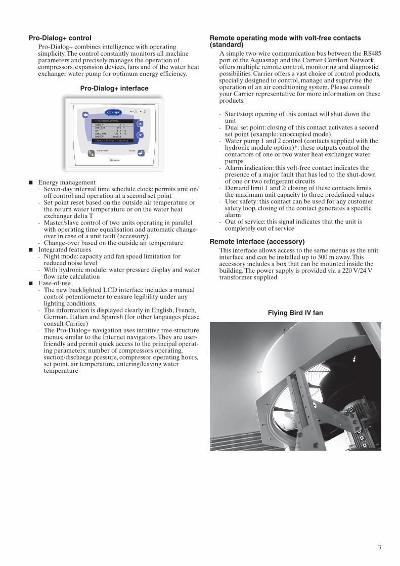
Partial view of the hydronic circuit
Superior reliabilityState-of-the-art concept
Cooperation with specialist laboratories and use of limit simulation tools (finite element calculations) for the design of the critical components, e.g. motor supports, suction/discharge piping etc.
Auto-adaptive controlControl algorithm prevents excessive compressor cycling and permits reduction of the water quantity in the hydronic circuit (Carrier patent)Hydronic module with integrated pressure transducers allowing measurement of the water pressure at two points, as well as measurement of the water flow rate and detection of lack of water and pressure. This considerably reduces the risk of problems such as frost accumulation on the water heat exchanger.Automatic compressor unloading in case of abnormally high condensing pressure. If an anomaly occurs (e.g. fouled air heat exchanger coil, fan failure) Aquasnap continues to operate, but at reduced capacity.
Exceptional endurance testsCorrosion resistance tests in salt mist in the laboratoryAccelerated ageing test on components that are submitted to continuous operation: compressor piping, fan supportsTransport simulation test in the laboratory on a vibrating table.
■
--
-
■
-
-
-
■
-
-
-
■
-
■
-
-
-
■
--
-
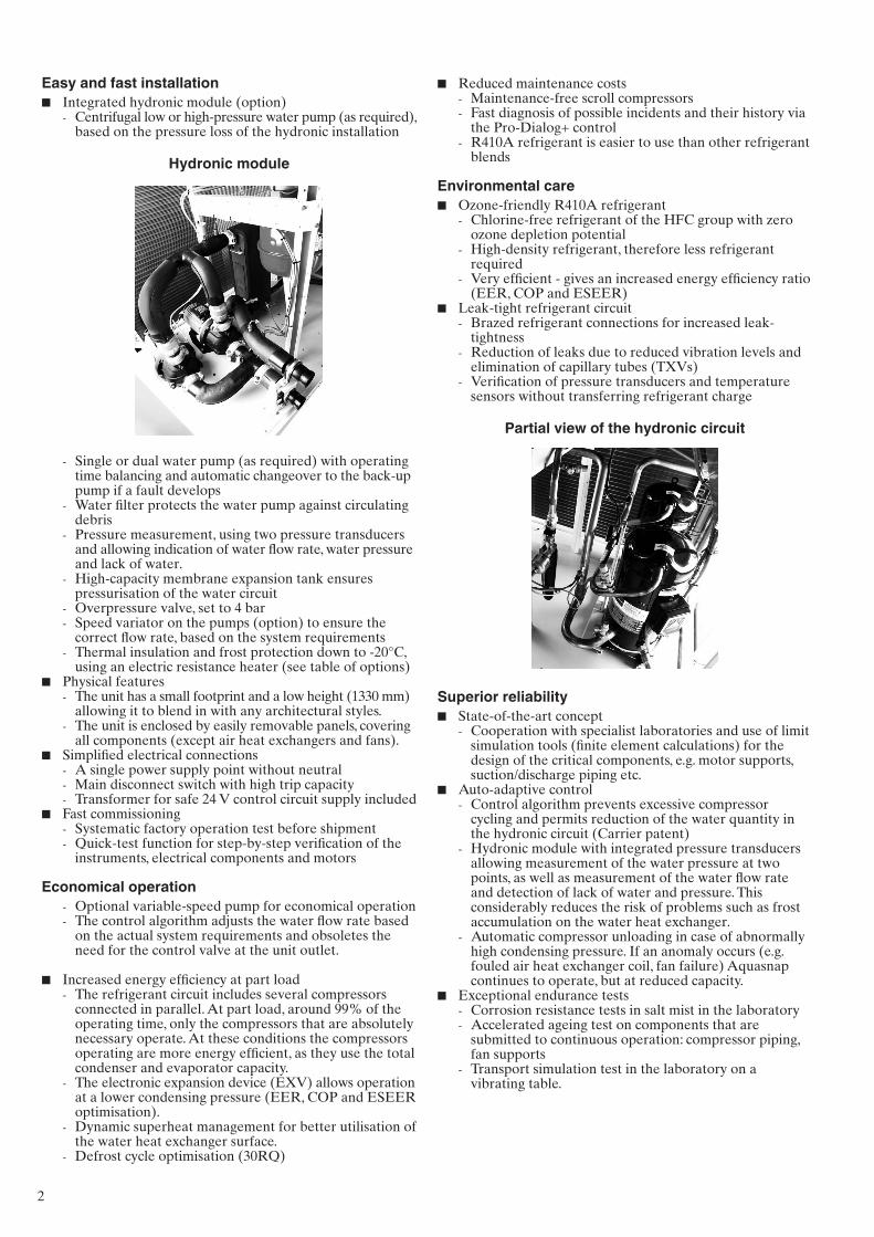
Easy and fast installationIntegrated hydronic module (option)
Centrifugal low or high-pressure water pump (as required), based on the pressure loss of the hydronic installation
Hydronic module
Single or dual water pump (as required) with operating time balancing and automatic changeover to the back-up pump if a fault developsWater filter protects the water pump against circulating debrisPressure measurement, using two pressure transducers and allowing indication of water flow rate, water pressure and lack of water.High-capacity membrane expansion tank ensures pressurisation of the water circuitOverpressure valve, set to 4 barSpeed variator on the pumps (option) to ensure the correct flow rate, based on the system requirementsThermal insulation and frost protection down to -�0°C, using an electric resistance heater (see table of options)
Physical featuresThe unit has a small footprint and a low height (1330 mm) allowing it to blend in with any architectural styles.The unit is enclosed by easily removable panels, covering all components (except air heat exchangers and fans).
Simplified electrical connectionsA single power supply point without neutralMain disconnect switch with high trip capacityTransformer for safe �4 V control circuit supply included
Fast commissioningSystematic factory operation test before shipmentQuick-test function for step-by-step verification of the instruments, electrical components and motors
Economical operationOptional variable-speed pump for economical operationThe control algorithm adjusts the water flow rate based on the actual system requirements and obsoletes the need for the control valve at the unit outlet.
Increased energy efficiency at part loadThe refrigerant circuit includes several compressors connected in parallel. At part load, around 99% of the operating time, only the compressors that are absolutely necessary operate. At these conditions the compressors operating are more energy efficient, as they use the total condenser and evaporator capacity.The electronic expansion device (EXV) allows operation at a lower condensing pressure (EER, COP and ESEER optimisation).Dynamic superheat management for better utilisation of the water heat exchanger surface.Defrost cycle optimisation (30RQ)
■
-
-
-
-
-
--
-
■
-
-
■
---
■
--
--
■
-
-
-
-
3
Flying Bird IV fan
Remote operating mode with volt-free contacts (standard)
A simple two-wire communication bus between the RS485 port of the Aquasnap and the Carrier Comfort Network offers multiple remote control, monitoring and diagnostic possibilities. Carrier offers a vast choice of control products, specially designed to control, manage and supervise the operation of an air conditioning system. Please consult your Carrier representative for more information on these products.
Start/stop: opening of this contact will shut down the unitDual set point: closing of this contact activates a second set point (example: unoccupied mode)Water pump 1 and � control (contacts supplied with the hydronic module option)*: these outputs control the contactors of one or two water heat exchanger water pumpsAlarm indication: this volt-free contact indicates the presence of a major fault that has led to the shut-down of one or two refrigerant circuitsDemand limit 1 and �: closing of these contacts limits the maximum unit capacity to three predefined valuesUser safety: this contact can be used for any customer safety loop, closing of the contact generates a specific alarmOut of service: this signal indicates that the unit is completely out of service
Remote interface (accessory)This interface allows access to the same menus as the unit interface and can be installed up to 300 m away. This accessory includes a box that can be mounted inside the building. The power supply is provided via a ��0 V/�4 V transformer supplied.
-
-
-
-
-
-
-
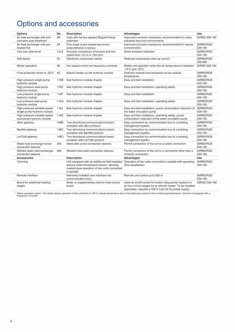
Pro-Dialog+ controlPro-Dialog+ combines intelligence with operating simplicity. The control constantly monitors all machine parameters and precisely manages the operation of compressors, expansion devices, fans and of the water heat exchanger water pump for optimum energy efficiency.
Pro-Dialog+ interface
\\MAINMENU\STATUS
Circuit B Total Capacity
CAPB_T 0 %DEM_LIM 100 %SP 4.2 °CCTRL_PNT -28.9 °CEMSTOP dsable
ENTERSTART/STOP
PRO-DIALOG+
Energy managementSeven-day internal time schedule clock: permits unit on/off control and operation at a second set pointSet point reset based on the outside air temperature or the return water temperature or on the water heat exchanger delta TMaster/slave control of two units operating in parallel with operating time equalisation and automatic change-over in case of a unit fault (accessory).Change-over based on the outside air temperature
Integrated featuresNight mode: capacity and fan speed limitation for reduced noise levelWith hydronic module: water pressure display and water flow rate calculation
Ease-of-useThe new backlighted LCD interface includes a manual control potentiometer to ensure legibility under any lighting conditions.The information is displayed clearly in English, French, German, Italian and Spanish (for other languages please consult Carrier)The Pro-Dialog+ navigation uses intuitive tree-structure menus, similar to the Internet navigators. They are user-friendly and permit quick access to the principal operat-ing parameters: number of compressors operating, suction/discharge pressure, compressor operating hours, set point, air temperature, entering/leaving water temperature
■
-
-
-
-■
-
-
■
-
-
-
4
Options and accessoriesOptions No. Description Advantages UseAir heat exchanger with anti-corrosion post-treatment
2B Coils with factory-applied Blygold Polual treatment
Improved corrosion resistance, recommended for urban, industrial and rural environments
30RBS 039-160
Air heat exchanger with pre-treated fins
3A Fins made of pre-treated aluminium (polyurethane or epoxy)
Improved corrosion resistance, recommended for marine environments
30RBS/RQS 039-160
Very low noise level 15LS Acoustic compressor enclosure and low-speed fans (12 r/s or 720 rpm)
Noise emission reduction 30RBS/RQS 039-160
Soft starter 25 Electronic compressor starter Reduced compressor start-up current 30RBS/RQS 039-080
Winter operation 28 Fan speed control via frequency converter Stable unit operation when the air temperature is between -10°C and -20°C
30RBS 039-160
Frost protection down to -20°C 42 Electric heater on the hydronic module Hydronic module frost protection at low outside temperature
30RBS/RQS 039-160
High-pressure single-pump hydronic module
116B See hydronic module chapter Easy and fast installation 30RBS/RQS 039-160
High-pressure dual-pump hydronic module
116C See hydronic module chapter Easy and fast installation, operating safety 30RBS/RQS 039-160
Low-pressure single-pump hydronic module
116F See hydronic module chapter Easy and fast installation 30RBS/RQS 039-160
Low-pressure dual-pump hydronic module
116G See hydronic module chapter Easy and fast installation, operating safety 30RBS/RQS 039-160
High-pressure variable-speed single-pump hydronic module
116J See hydronic module chapter Easy and fast installation, power consumption reduction of the water circulation pump
30RBS/RQS 039-160
High-pressure variable-speed dual-pump hydronic module
116K See hydronic module chapter Easy and fast installation, operating safety, power consumption reduction of the water circulation pump
30RBS/RQS 039-160
JBus gateway 148B Two-directional communications board, complies with JBus protocol
Easy connection by communication bus to a building management system
30RBS/RQS 039-160
BacNet gateway 148C Two-directional communications board, complies with BacNet protocol
Easy connection by communication bus to a building management system
30RBS/RQS 039-160
LonTalk gateway 148D Two-directional communications board, complies with LonTalk protocol
Easy connection by communication bus to a building management system
30RBS/RQS 039-160
Water heat exchanger screw connection sleeves
264 Inlet/outlet screw connection sleeves Permit connection of the unit to a screw connection 30RBS/RQS 039-160
Welded water heat exchanger connection sleeves
266 Welded inlet/outlet connection sleeves Permit connection of the unit to a connection other than a Victaulic connection
30RBS/RQS 039-160
Accessories Description Advantages UseTwinning Unit equipped with an additional field-installed
leaving water temperature sensor, allowing master/slave operation of two units connected in parallel
Operation of two units connected in parallel with operating time equalisation
30RBS/RQS 039-160
Remote interface Remotely installed user interface (via communication bus).
Remote unit control up to 300 m 30RBS/RQS 039-160
Board for additional heating stages
Boiler or supplementary electric heat control board
Used as on/off control for boilers (Aquasmart system) or as four control stages for an electric heater. To be installed separately, requires a 400 V-3 ph-50 Hz power supply.
30RQS 039-160
* Winter operation option: This option allows operation of the unit down to -20°C outside temperature due to the optimised control of the condensing temperature. One fan is equipped with a frequency converter.
5
Physical data, 30RBS30RBS 039 045 050 060 070 080 090 100 120 140 160Nominal cooling capacity, standard unit* kW 39.3 44.6 51.9 58.4 66.7 78.6 89.4 99.9 117.0 134.3 157.1Power input kW 13.7 16.1 18.9 21.2 24.4 29.0 31.8 35.9 43.2 49.1 57.9EER kW/kW 2.88 2.77 2.75 2.76 2.74 2.71 2.81 2.78 2.71 2.74 2.71Eurovent class, cooling C C C C C C C C C C CPart-load performanceESEER kW/kW 4.04 4.09 4.07 4.06 4.04 4.04 4.22 4.20 4.12 4.14 4.13IPLV kW/kW 4.71 4.69 4.70 4.72 4.56 4.76 4.67 4.61 4.67 4.53 4.66Nominal cooling capacity, standard unit** kW 52.6 59.2 72.7 80.2 81.8 107.0 120.1 133.1 154.6 184.2 218.2Power input kW 15 17 20 23 26 30 35 40 48 52 62EER kW/kW 3.4 3.3 3.4 3.4 3.1 3.3 3.3 3.2 3.1 3.4 3.4Operating weight***Standard unit without hydronic module kg 458 466 489 515 502 533 835 845 876 982 1046Standard unit with hydronic moduleSingle high-pressure pump kg 488 496 519 545 531 562 867 877 912 1021 1085Dual high-pressure pump kg 514 522 545 571 557 588 912 922 960 1058 1122Sound levelsStandard unitSound power level 10-12 W**** dB(A) 80 81 81 81 87 87 84 84 84 90 90Sound pressure level at 10 m† dB(A) 49 49 49 49 55 55 52 52 52 58 58Unit with option 15LS (very low sound level)Sound power level 10-12 W**** dB(A) 79 80 80 80 80 80 83 83 83 83 83Sound pressure level at 10 m† dB(A) 48 48 48 48 48 48 51 51 51 51 51Compressors Hermetic scroll compressors, 48.3 r/sCircuit A 2 2 2 2 2 2 3 3 3 2 2Circuit B - - - - - - - - - 2 2Number of capacity stages 2 2 2 2 2 2 3 3 3 4 4Refrigerant R-410ACircuit A kg 8.5 9.0 12.5 15.0 12.5 15.5 19.0 20.0 25.0 12.5 16.0Circuit B kg - - - - - - - - - 12.5 16.0Capacity control Pro-Dialog +Minimum capacity % 50 50 50 50 50 50 33 33 33 25 25Condensers Grooved copper tubes and aluminium finsFans Axial Flying Bird IV with rotating shroudQuantity 1 1 1 1 1 1 2 2 2 2 2Total air flow (at high speed) l/s 3800 3800 3800 3800 5300 5300 7600 7600 7600 10600 10600Speed r/s 12 12 12 12 12 16 12 12 12 16 16Evaporator Direct expansion. plate heat exchangerWater volume l 2.6 3.0 3.3 4.0 4.8 5.6 8.7 9.9 11.3 12.4 14.7Without hydronic moduleMax. water-side operating pressure kPa 1000 1000 1000 1000 1000 1000 1000 1000 1000 1000 1000With hydronic module (option)Single or dual pump (as selected) Pump, Victaulic screen filter, safety valve, expansion tank, purge valves (water + air), pressure sensorsExpansion tank volume l 12 12 12 12 12 12 35 35 35 35 35Expansion tank pressure†† bar 1 1 1 1 1 1 1.5 1.5 1.5 1.5 1.5Max. water-side operating pressure kPa 400 400 400 400 400 400 400 400 400 400 400Water connections with/without hydronic module VictaulicDiameter in 2 2 2 2 2 2 2 2 2 2 2Outside diameter mm 60.3 60.3 60.3 60.3 60.3 60.3 60.3 60.3 60.3 60.3 60.3Chassis paint colour Colour code: RAL7035
* Standard Eurovent LCP/A/P/C/AC conditions in cooling mode: evaporator entering/leaving water temperature 12°C/7°C, outside air temperature 35°C, evaporator fouling factor 0.18 x 10⁻⁴ (m2 K)/W ** Standard Eurovent LCP/A/P/C/CHF conditions in cooling mode: evaporator entering/leaving water temperature 23°C/18°C, outside air temperature 35°C, evaporator fouling factor 0.18 x 10⁻⁴ (m2 K)/W *** Weight shown is a guideline only. To find out the unit refrigerant charge, please refer to the unit nameplate. **** In accordance with ISO 9614-1 and certified by Eurovent. The values have been rounded and are for information only and not contractually binding † For information, calculated from the sound power level Lw(A) †† When delivered, the standard pre-inflation of the tank is not necessarily the optimal value for the system. To permit changing the water volume, change the inflation pressure to a pressure that is
close to the static head of the system.
6
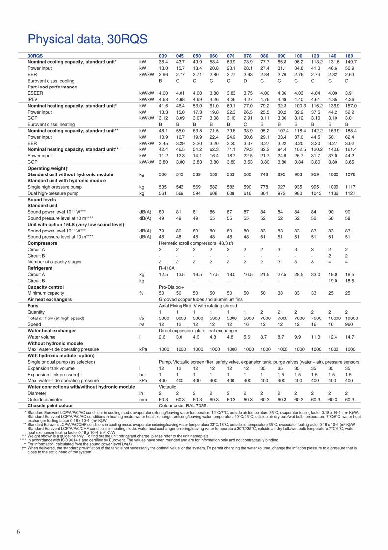
Physical data, 30RQS30RQS 039 045 050 060 070 078 080 090 100 120 140 160Nominal cooling capacity, standard unit* kW 38.4 43.7 49.9 58.4 63.9 73.9 77.7 85.8 96.2 113.2 131.6 149.7Power input kW 13.0 15.7 18.4 20.8 23.1 28.1 27.4 31.1 34.8 41.3 46.6 56.9EER kW/kW 2.96 2.77 2.71 2.80 2.77 2.63 2.84 2.76 2.76 2.74 2.82 2.63Eurovent class, cooling B C C C C D C C C C C DPart-load performanceESEER kW/kW 4.00 4.01 4.00 3.80 3.83 3.75 4.00 4.06 4.03 4.04 4.00 3.91IPLV kW/kW 4.68 4.68 4.69 4.26 4.26 4.27 4.76 4.49 4.40 4.61 4.35 4.36Nominal heating capacity, standard unit* kW 41.6 46.4 53.0 61.0 69.1 77.0 79.2 92.3 100.3 116.2 136.9 157.0Power input kW 13.3 15.0 17.3 19.8 22.3 26.5 25.5 30.2 32.2 37.5 44.2 52.2COP kW/kW 3.12 3.09 3.07 3.08 3.10 2.91 3.11 3.06 3.12 3.10 3.10 3.01Eurovent class, heating B B B B B C B B B B B BNominal cooling capacity, standard unit** kW 48.1 55.0 63.8 71.5 79.6 93.9 95.2 107.4 118.4 142.2 163.9 188.4Power input kW 13.9 16.7 19.9 22.4 24.9 30.6 29.1 33.4 37.0 44.5 50.1 62.4EER kW/kW 3.45 3.29 3.20 3.20 3.20 3.07 3.27 3.22 3.20 3.20 3.27 3.02Nominal heating capacity, standard unit** kW 42.4 46.5 54.2 62.3 71.1 79.3 82.2 94.4 102.5 120.2 140.6 161.4Power input kW 11.2 12.3 14.1 16.4 18.7 22.5 21.7 24.9 26.7 31.7 37.0 44.2COP kW/kW 3.80 3.80 3.83 3.80 3.80 3.53 3.80 3.80 3.84 3.80 3.80 3.65Operating weight†Standard unit without hydronic module kg 506 513 539 552 553 560 748 895 903 959 1060 1078Standard unit with hydronic moduleSingle high-pressure pump kg 535 543 569 582 582 590 778 927 935 995 1099 1117Dual high-pressure pump kg 561 569 594 608 608 616 804 972 980 1043 1136 1127Sound levelsStandard unitSound power level 10-12 W*** dB(A) 80 81 81 86 87 87 84 84 84 84 90 90Sound pressure level at 10 m**** dB(A) 49 49 49 55 55 55 52 52 52 52 58 58Unit with option 15LS (very low sound level)Sound power level 10-12 W*** dB(A) 79 80 80 80 80 80 83 83 83 83 83 83Sound pressure level at 10 m**** dB(A) 48 48 48 48 48 48 51 51 51 51 51 51Compressors Hermetic scroll compressors, 48.3 r/sCircuit A 2 2 2 2 2 2 2 3 3 3 2 2Circuit B - - - - - - - - - - 2 2Number of capacity stages 2 2 2 2 2 2 2 3 3 3 4 4Refrigerant R-410ACircuit A kg 12.5 13.5 16.5 17.5 18.0 16.5 21.5 27.5 28.5 33.0 19.0 18.5Circuit B kg - - - - - - - - - - 19.0 18.5Capacity control Pro-Dialog +Minimum capacity % 50 50 50 50 50 50 50 33 33 33 25 25Air heat exchangers Grooved copper tubes and aluminium finsFans Axial Flying Bird IV with rotating shroudQuantity 1 1 1 1 1 1 2 2 2 2 2 2Total air flow (at high speed) l/s 3800 3800 3800 5300 5300 5300 7600 7600 7600 7600 10600 10600Speed r/s 12 12 12 12 12 16 12 12 12 16 16 960Water heat exchanger Direct expansion. plate heat exchangerWater volume l 2.6 3.0 4.0 4.8 4.8 5.6 8.7 8.7 9.9 11.3 12.4 14.7Without hydronic moduleMax. water-side operating pressure kPa 1000 1000 1000 1000 1000 1000 1000 1000 1000 1000 1000 1000With hydronic module (option)Single or dual pump (as selected) Pump, Victaulic screen filter, safety valve, expansion tank, purge valves (water + air), pressure sensorsExpansion tank volume l 12 12 12 12 12 12 35 35 35 35 35 35Expansion tank pressure†† bar 1 1 1 1 1 1 1 1.5 1.5 1.5 1.5 1.5Max. water-side operating pressure kPa 400 400 400 400 400 400 400 400 400 400 400 400Water connections with/without hydronic module VictaulicDiameter in 2 2 2 2 2 2 2 2 2 2 2 2Outside diameter mm 60.3 60.3 60.3 60.3 60.3 60.3 60.3 60.3 60.3 60.3 60.3 60.3Chassis paint colour Colour code: RAL 7035
* Standard Eurovent LCP/A/P/C/AC conditions in cooling mode: evaporator entering/leaving water temperature 12°C/7°C, outside air temperature 35°C, evaporator fouling factor 0.18 x 10⁻⁴ (m2 K)/W. Standard Eurovent LCP/A/P/C/AC conditions in heating mode: water heat exchanger entering/leaving water temperature 40°C/45°C, outside air dry bulb/wet bulb temperature 7°C/6°C, water heat
exchanger fouling factor 0.18 x 10⁻⁴ (m2 K)/W ** Standard Eurovent LCP/A/P/C/CHF conditions in cooling mode: evaporator entering/leaving water temperature 23°C/18°C, outside air temperature 35°C, evaporator fouling factor 0.18 x 10⁻⁴ (m2 K)/W Standard Eurovent LCP/A/P/C/CHF conditions in heating mode: water heat exchanger entering/leaving water temperature 30°C/35°C, outside air dry bulb/wet bulb temperature 7°C/6°C, water
heat exchanger fouling factor 0.18 x 10⁻⁴ (m2 K)/W *** Weight shown is a guideline only. To find out the unit refrigerant charge, please refer to the unit nameplate. **** In accordance with ISO 9614-1 and certified by Eurovent. The values have been rounded and are for information only and not contractually binding † For information, calculated from the sound power level Lw(A) †† When delivered, the standard pre-inflation of the tank is not necessarily the optimal value for the system. To permit changing the water volume, change the inflation pressure to a pressure that is
close to the static head of the system.
�
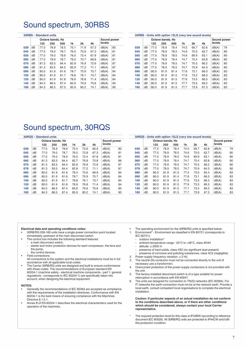
Sound spectrum, 30RBS30RBS - Units with option 15LS (very low sound levels)
Octave bands, Hz Sound power levels125 250 500 1k 2k 4k
039 dB 77.0 78.9 78.4 74.5 69.7 62.6 dB(A) 79045 dB 77.0 78.9 78.5 74.6 70.0 62.7 dB(A) 80050 dB 77.0 78.9 78.5 74.6 69.9 63.1 dB(A) 80060 dB 77.0 78.9 78.4 74.7 70.4 63.8 dB(A) 80070 dB 77.0 78.9 78.5 74.7 70.5 66.2 dB(A) 80080 dB 77.0 78.9 78.5 74.7 70.9 64.3 dB(A) 80090 dB 80.0 81.9 81.4 77.6 73.1 66.0 dB(A) 83100 dB 80.0 81.9 81.5 77.6 73.2 68.3 dB(A) 83120 dB 80.0 81.9 81.5 77.6 73.5 66.5 dB(A) 83140 dB 80.0 81.9 81.5 77.7 73.5 69.2 dB(A) 83160 dB 80.0 81.9 81.5 77.7 73.9 67.3 dB(A) 83
30RBS – Standard unitsOctave bands, Hz Sound power
levels125 250 500 1k 2k 4k039 dB 77.0 78.9 78.5 75.1 71.9 67.2 dB(A) 80045 dB 77.0 79.0 78.7 76.0 72.8 67.3 dB(A) 81050 dB 77.0 79.0 78.9 76.0 72.4 67.8 dB(A) 81060 dB 77.0 78.9 78.7 76.0 73.7 68.8 dB(A) 81070 dB 81.3 83.5 84.4 82.9 76.9 72.6 dB(A) 87080 dB 81.3 83.5 84.5 82.9 77.2 71.1 dB(A) 87090 dB 80.0 81.9 81.6 78.7 75.9 70.7 dB(A) 84100 dB 80.0 81.9 81.7 78.8 76.1 73.7 dB(A) 84120 dB 80.0 81.9 81.8 78.9 76.8 71.4 dB(A) 84140 dB 84.3 86.5 87.4 85.9 79.9 75.6 dB(A) 90160 dB 84.3 86.5 87.5 85.9 80.2 74.1 dB(A) 90
Sound spectrum, 30RQS30RQS – Standard units
Octave bands, Hz Sound power levels125 250 500 1k 2k 4k
039 dB 77.0 78.9 78.6 75.4 72.6 66.9 dB(A) 80045 dB 77.0 79.0 78.7 76.0 72.8 67.3 dB(A) 81050 dB 77.0 79.0 78.9 76.0 72.4 67.8 dB(A) 81060 dB 81.3 83.5 84.4 82.7 76.8 70.8 dB(A) 86070 dB 81.3 83.5 84.4 82.8 76.9 72.6 dB(A) 87078 dB 81.3 93.5 84.4 82.8 77.2 71.1 dB(A) 87080 dB 80.0 81.9 81.6 78.4 75.6 69.9 dB(A) 84090 dB 80.0 81.9 81.6 78.7 75.9 70.7 dB(A) 84100 dB 80.0 81.9 81.7 78.8 76.1 73.7 dB(A) 84120 dB 80.0 81.9 81.8 78.9 76.8 71.4 dB(A) 84140 dB 84.3 86.5 87.4 85.8 79.9 75.6 dB(A) 90160 dB 84.3 86.5 87.4 85.9 80.2 74.1 dB(A) 90
30RQS - Units with option 15LS (very low sound levels)Octave bands, Hz Sound power
levels125 250 500 1k 2k 4k039 dB 77.0 78.9 78.4 74.5 69.7 62.6 dB(A) 79045 dB 77.0 78.9 78.5 74.6 70.0 62.7 dB(A) 80050 dB 77.0 78.9 78.5 74.6 69.9 63.1 dB(A) 80060 dB 77.0 78.9 78.4 74.7 70.4 63.8 dB(A) 80070 dB 77.0 78.9 78.5 74.7 70.5 66.2 dB(A) 80078 dB 77.0 78.9 78.5 74.7 70.9 64.3 dB(A) 80080 dB 80.0 81.9 81.5 77.5 73.0 65.4 dB(A) 83090 dB 80.0 81.9 81.4 77.6 73.1 66.0 dB(A) 83100 dB 80.0 81.9 81.5 77.6 73.2 68.3 dB(A) 83120 dB 80.0 81.9 81.5 77.6 73.5 66.5 dB(A) 83140 dB 80.0 81.9 81.5 77.7 73.5 69.2 dB(A) 83160 dB 80.0 81.9 81.5 77.7 73.9 67.3 dB(A) 83
Electrical data and operating conditions notes:• 30RB/RQ 039-160 units have a single power connection point located
immediately upstream of the main disconnect switch.• The control box includes the following standard features: - a main disconnect switch, - starter and motor protection devices for each compressor, the fans and
the pump, - the control devices.• Field connections: All connections to the system and the electrical installations must be in full
accordance with all applicable local codes.• The Carrier 30RB/RQ units are designed and built to ensure conformance
with these codes. The recommendations of European standard EN 60204-1 (machine safety - electrical machine components - part 1: general regulations - corresponds to IEC 60204-1) are specifically taken into account, when designing the electrical equipment.
NOTES: • Generally the recommendations of IEC 60364 are accepted as compliance
with the requirements of the installation directives. Conformance with EN 60204-1 is the best means of ensuring compliance with the Machines Directive § 1.5.1.
• Annex B of EN 60204-1 describes the electrical characteristics used for the operation of the machines.
• The operating environment for the 30RB/RQ units is specified below:1. Environment* - Environment as classified in EN 60721 (corresponds to
IEC 60721): - outdoor installation* - ambient temperature range: -20°C to +48°C, class 4K4H - altitude: ≤ 2000 m - presence of hard solids, class 4S2 (no significant dust present) - presence of corrosive and polluting substances, class 4C2 (negligible)2. Power supply frequency variation: ± 2 Hz.3. The neutral (N) conductor must not be connected directly to the unit (if
necessary use a transformer).4. Overcurrent protection of the power supply conductors is not provided with
the unit.5. The factory-installed disconnect switch is of a type suitable for power
interruption in accordance with EN 60947.6. The units are designed for connection to TN(S) networks (IEC 60364). For
IT networks the earth connection must not be at the network earth. Provide a local earth, consult competent local organisations to complete the electrical installation.
Caution: If particular aspects of an actual installation do not conform to the conditions described above, or if there are other conditions which should be considered, always contact your local Carrier representative.
* The required protection level for this class is IP43BW (according to reference document IEC 60529). All 30RB/RQ units are protected to IP44CW and fulfil this protection condition.
8
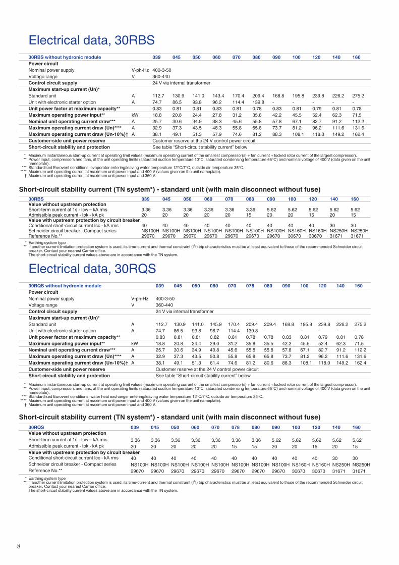
Electrical data, 30RBS30RBS without hydronic module 039 045 050 060 070 080 090 100 120 140 160Power circuitNominal power supply V-ph-Hz 400-3-50Voltage range V 360-440Control circuit supply 24 V via internal transformerMaximum start-up current (Un)*Standard unit A 112.7 130.9 141.0 143.4 170.4 209.4 168.8 195.8 239.8 226.2 275.2Unit with electronic starter option A 74.7 86.5 93.8 96.2 114.4 139.8 - - - - -Unit power factor at maximum capacity** 0.83 0.81 0.81 0.83 0.81 0.78 0.83 0.81 0.79 0.81 0.78Maximum operating power input** kW 18.8 20.8 24.4 27.8 31.2 35.8 42.2 45.5 52.4 62.3 71.5Nominal unit operating current draw*** A 25.7 30.6 34.9 38.3 45.6 55.8 57.8 67.1 82.7 91.2 112.2Maximum operating current draw (Un)**** A 32.9 37.3 43.5 48.3 55.8 65.8 73.7 81.2 96.2 111.6 131.6Maximum operating current draw (Un-10%)† A 38.1 49.1 51.3 57.9 74.6 81.2 88.3 108.1 118.0 149.2 162.4Customer-side unit power reserve Customer reserve at the 24 V control power circuitShort-circuit stability and protection See table “Short-circuit stability current” below
* Maximum instantaneous start-up current at operating limit values (maximum operating current of the smallest compressor(s) + fan current + locked rotor current of the largest compressor). ** Power input, compressors and fans, at the unit operating limits (saturated suction temperature 10°C, saturated condensing temperature 65°C) and nominal voltage of 400 V (data given on the unit
nameplate). *** Standardised Eurovent conditions: evaporator entering/leaving water temperature 12°C/7°C, outside air temperature 35°C. **** Maximum unit operating current at maximum unit power input and 400 V (values given on the unit nameplate). † Maximum unit operating current at maximum unit power input and 360 V.
Short-circuit stability current (TN system*) - standard unit (with main disconnect without fuse)30RBS 039 045 050 060 070 080 090 100 120 140 160Value without upstream protectionShort-term current at 1s - Icw – kA rms 3.36 3.36 3.36 3.36 3.36 3.36 5.62 5.62 5.62 5.62 5.62Admissible peak current - Ipk - kA pk 20 20 20 20 20 15 20 20 15 20 15Value with upstream protection by circuit breakerConditional short-circuit current Icc - kA rms 40 40 40 40 40 40 40 40 40 30 30Schneider circuit breaker - Compact series NS100H NS100H NS100H NS100H NS100H NS100H NS100H NS160H NS160H NS250H NS250HReference No.** 29670 29670 29670 29670 29670 29670 29670 30670 30670 31671 31671
* Earthing system type ** If another current limitation protection system is used, its time-current and thermal constraint (I²t) trip characteristics must be at least equivalent to those of the recommended Schneider circuit
breaker. Contact your nearest Carrier office. The short-circuit stability current values above are in accordance with the TN system.
Electrical data, 30RQS30RQS without hydronic module 039 045 050 060 070 078 080 090 100 120 140 160Power circuitNominal power supply V-ph-Hz 400-3-50Voltage range V 360-440Control circuit supply 24 V via internal transformerMaximum start-up current (Un)*Standard unit A 112.7 130.9 141.0 145.9 170.4 209.4 209.4 168.8 195.8 239.8 226.2 275.2Unit with electronic starter option A 74.7 86.5 93.8 98.7 114.4 139.8 - - - - - -Unit power factor at maximum capacity** 0.83 0.81 0.81 0.82 0.81 0.78 0.78 0.83 0.81 0.79 0.81 0.78Maximum operating power input** kW 18.8 20.8 24.4 29.0 31.2 35.8 35.5 42.2 45.5 52.4 62.3 71.5Nominal unit operating current draw*** A 25.7 30.6 34.9 40.8 45.6 55.8 55.8 57.8 67.1 82.7 91.2 112.2Maximum operating current draw (Un)**** A 32.9 37.3 43.5 50.8 55.8 65.8 65.8 73.7 81.2 96.2 111.6 131.6Maximum operating current draw (Un-10%)† A 38.1 49.1 51.3 61.4 74.6 81.2 80.6 88.3 108.1 118.0 149.2 162.4Customer-side unit power reserve Customer reserve at the 24 V control power circuitShort-circuit stability and protection See table “Short-circuit stability current” below
* Maximum instantaneous start-up current at operating limit values (maximum operating current of the smallest compressor(s) + fan current + locked rotor current of the largest compressor). ** Power input, compressors and fans, at the unit operating limits (saturated suction temperature 10°C, saturated condensing temperature 65°C) and nominal voltage of 400 V (data given on the unit
nameplate). *** Standardised Eurovent conditions: water heat exchanger entering/leaving water temperature 12°C/7°C, outside air temperature 35°C. **** Maximum unit operating current at maximum unit power input and 400 V (values given on the unit nameplate). † Maximum unit operating current at maximum unit power input and 360 V.
Short-circuit stability current (TN system*) - standard unit (with main disconnect without fuse)30RQS 039 045 050 060 070 078 080 090 100 120 140 160Value without upstream protectionShort-term current at 1s - Icw – kA rms 3,36 3,36 3,36 3,36 3,36 3,36 3,36 5,62 5,62 5,62 5,62 5,62Admissible peak current - Ipk - kA pk 20 20 20 20 20 15 15 20 20 15 20 15Value with upstream protection by circuit breakerConditional short-circuit current Icc - kA rms 40 40 40 40 40 40 40 40 40 40 30 30Schneider circuit breaker - Compact series NS100H NS100H NS100H NS100H NS100H NS100H NS100H NS100H NS160H NS160H NS250H NS250HReference No.** 29670 29670 29670 29670 29670 29670 29670 29670 30670 30670 31671 31671
* Earthing system type ** If another current limitation protection system is used, its time-current and thermal constraint (I²t) trip characteristics must be at least equivalent to those of the recommended Schneider circuit
breaker. Contact your nearest Carrier office. The short-circuit stability current values above are in accordance with the TN system.
9
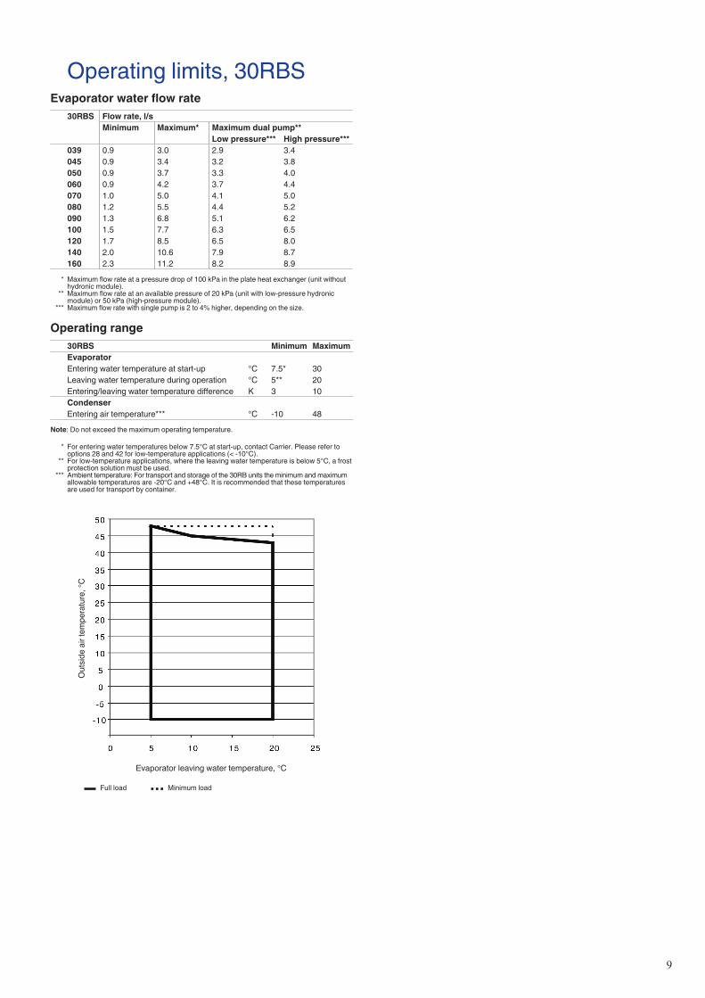
Operating limits, 30RBSEvaporator water flow rate
30RBS Flow rate, l/sMinimum Maximum* Maximum dual pump**
Low pressure*** High pressure***039 0.9 3.0 2.9 3.4045 0.9 3.4 3.2 3.8050 0.9 3.7 3.3 4.0060 0.9 4.2 3.7 4.4070 1.0 5.0 4.1 5.0080 1.2 5.5 4.4 5.2090 1.3 6.8 5.1 6.2100 1.5 7.7 6.3 6.5120 1.7 8.5 6.5 8.0140 2.0 10.6 7.9 8.7160 2.3 11.2 8.2 8.9
* Maximum flow rate at a pressure drop of 100 kPa in the plate heat exchanger (unit without hydronic module).
** Maximum flow rate at an available pressure of 20 kPa (unit with low-pressure hydronic module) or 50 kPa (high-pressure module).
*** Maximum flow rate with single pump is 2 to 4% higher, depending on the size.
Operating range30RBS Minimum MaximumEvaporatorEntering water temperature at start-up °C 7.5* 30Leaving water temperature during operation °C 5** 20Entering/leaving water temperature difference K 3 10CondenserEntering air temperature*** °C -10 48
Note: Do not exceed the maximum operating temperature.
* For entering water temperatures below 7.5°C at start-up, contact Carrier. Please refer to options 28 and 42 for low-temperature applications (< -10°C).
** For low-temperature applications, where the leaving water temperature is below 5°C, a frost protection solution must be used.
*** Ambient temperature: For transport and storage of the 30RB units the minimum and maximum allowable temperatures are -20°C and +48°C. It is recommended that these temperatures are used for transport by container.
Out
side
air
tem
pera
ture
, °C
Evaporator leaving water temperature, °C
Full load Minimum load
10
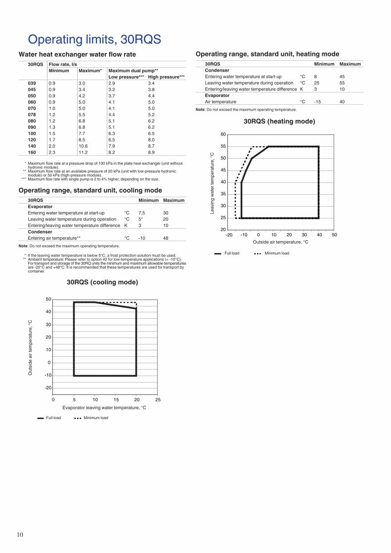
Operating limits, 30RQSWater heat exchanger water flow rate
30RQS Flow rate, l/sMinimum Maximum* Maximum dual pump**
Low pressure*** High pressure***039 0.9 3.0 2.9 3.4045 0.9 3.4 3.2 3.8050 0.9 4.2 3.7 4.4060 0.9 5.0 4.1 5.0070 1.0 5.0 4.1 5.0078 1.2 5.5 4.4 5.2080 1.2 6.8 5.1 6.2090 1.3 6.8 5.1 6.2100 1.5 7.7 6.3 6.5120 1.7 8.5 6.5 8.0140 2.0 10.6 7.9 8.7160 2.3 11.2 8.2 8.9
* Maximum flow rate at a pressure drop of 100 kPa in the plate heat exchanger (unit without hydronic module).
** Maximum flow rate at an available pressure of 20 kPa (unit with low-pressure hydronic module) or 50 kPa (high-pressure module).
*** Maximum flow rate with single pump is 2 to 4% higher, depending on the size.
Operating range, standard unit, cooling mode30RQS Minimum MaximumEvaporatorEntering water temperature at start-up °C 7,5 30Leaving water temperature during operation °C 5* 20Entering/leaving water temperature difference K 3 10CondenserEntering air temperature** °C -10 48
Note: Do not exceed the maximum operating temperature.
* If the leaving water temperature is below 5°C, a frost protection solution must be used. ** Ambient temperature: Please refer to option 42 for low-temperature applications (< -10°C).
For transport and storage of the 30RQ units the minimum and maximum allowable temperatures are -20°C and +48°C. It is recommended that these temperatures are used for transport by container.
30RQS (cooling mode)
-20
-10
0
10
20
30
40
50
0 5 10 15 20 25
Full load Minimum load
Operating range, standard unit, heating mode30RQS Minimum MaximumCondenserEntering water temperature at start-up °C 8 45Leaving water temperature during operation °C 25 55Entering/leaving water temperature difference K 3 10EvaporatorAir temperature °C -15 40
Note: Do not exceed the maximum operating temperature.
30RQS (heating mode)
20
25
30
35
40
45
50
55
60
-20 -10 0 10 20 30 40 50
Leav
ing
wat
er te
mpe
ratu
re, °
C
Outside air temperature, °C
Full load Minimum load
Out
side
air
tem
pera
ture
, °C
Evaporator leaving water temperature, °C
11
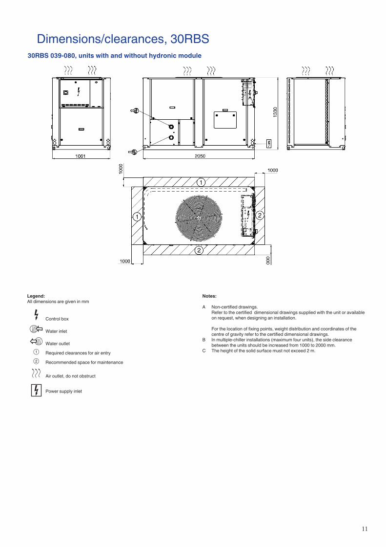
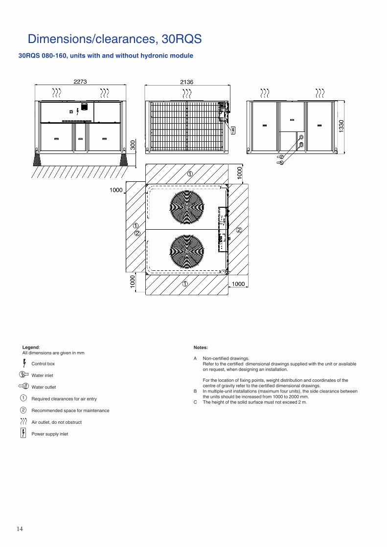
Legend:All dimensions are given in mm
Control box
Water inlet
Water outlet
1 Required clearances for air entry
2 Recommended space for maintenance
Air outlet, do not obstruct
Power supply inlet
Notes:
A Non-certified drawings. Refer to the certified dimensional drawings supplied with the unit or available
on request, when designing an installation.
For the location of fixing points, weight distribution and coordinates of the centre of gravity refer to the certified dimensional drawings.
B In multiple-chiller installations (maximum four units), the side clearance between the units should be increased from 1000 to 2000 mm.
C The height of the solid surface must not exceed 2 m.
Dimensions/clearances, 30RBS30RBS 039-080, units with and without hydronic module
1�
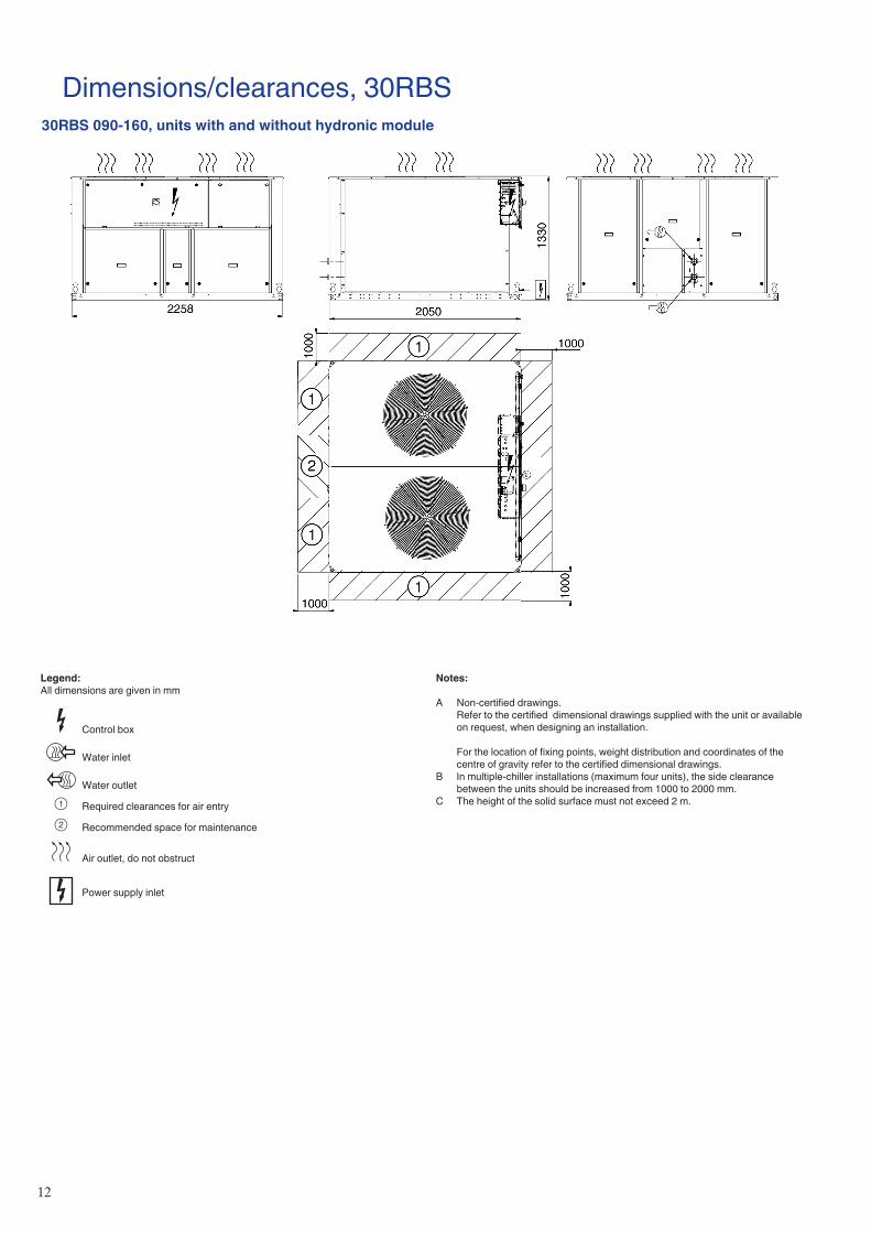
Notes:
A Non-certified drawings. Refer to the certified dimensional drawings supplied with the unit or available
on request, when designing an installation.
For the location of fixing points, weight distribution and coordinates of the centre of gravity refer to the certified dimensional drawings.
B In multiple-chiller installations (maximum four units), the side clearance between the units should be increased from 1000 to 2000 mm.
C The height of the solid surface must not exceed 2 m.
Dimensions/clearances, 30RBS30RBS 090-160, units with and without hydronic module
Legend:All dimensions are given in mm
Control box
Water inlet
Water outlet
1 Required clearances for air entry
2 Recommended space for maintenance
Air outlet, do not obstruct
Power supply inlet
13
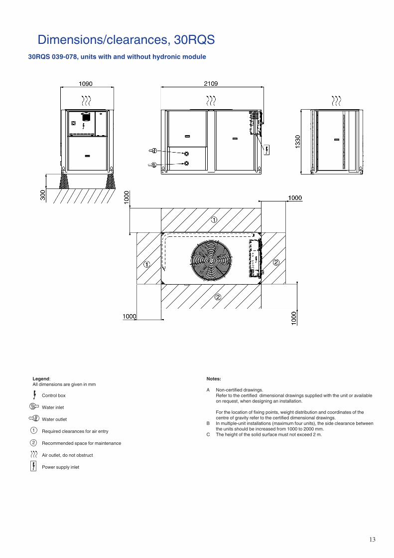
Dimensions/clearances, 30RQS30RQS 039-078, units with and without hydronic module
Notes:
A Non-certified drawings. Refer to the certified dimensional drawings supplied with the unit or available
on request, when designing an installation.
For the location of fixing points, weight distribution and coordinates of the centre of gravity refer to the certified dimensional drawings.
B In multiple-unit installations (maximum four units), the side clearance between the units should be increased from 1000 to 2000 mm.
C The height of the solid surface must not exceed 2 m.
Legend:All dimensions are given in mm
Control box
Water inlet
Water outlet
Required clearances for air entry
Recommended space for maintenance
Air outlet, do not obstruct
Power supply inlet
1
2
14
Dimensions/clearances, 30RQS30RQS 080-160, units with and without hydronic module
Notes:
A Non-certified drawings. Refer to the certified dimensional drawings supplied with the unit or available
on request, when designing an installation.
For the location of fixing points, weight distribution and coordinates of the centre of gravity refer to the certified dimensional drawings.
B In multiple-unit installations (maximum four units), the side clearance between the units should be increased from 1000 to 2000 mm.
C The height of the solid surface must not exceed 2 m.
Legend:All dimensions are given in mm
Control box
Water inlet
Water outlet
Required clearances for air entry
Recommended space for maintenance
Air outlet, do not obstruct
Power supply inlet
1
2
15
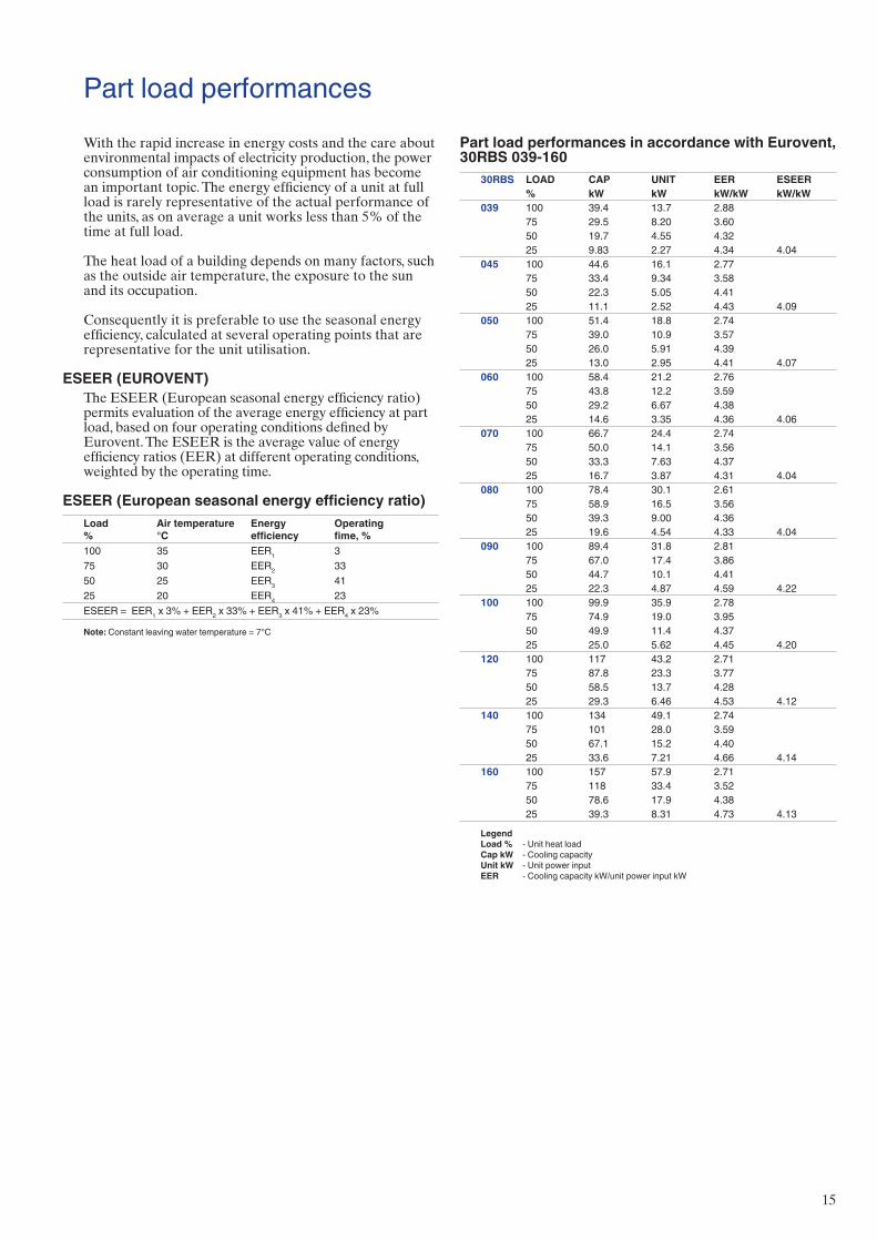
Part load performancesWith the rapid increase in energy costs and the care about environmental impacts of electricity production, the power consumption of air conditioning equipment has become an important topic. The energy efficiency of a unit at full load is rarely representative of the actual performance of the units, as on average a unit works less than 5% of the time at full load.
The heat load of a building depends on many factors, such as the outside air temperature, the exposure to the sun and its occupation.
Consequently it is preferable to use the seasonal energy efficiency, calculated at several operating points that are representative for the unit utilisation.
ESEER (EUROVENT)The ESEER (European seasonal energy efficiency ratio) permits evaluation of the average energy efficiency at part load, based on four operating conditions defined by Eurovent. The ESEER is the average value of energy efficiency ratios (EER) at different operating conditions, weighted by the operating time.
ESEER (European seasonal energy efficiency ratio)Load%
Air temperature °C
Energy efficiency
Operating fime, %
100 35 EER1 375 30 EER2 3350 25 EER3 4125 20 EER4 23ESEER = EER1 x 3% + EER2 x 33% + EER3 x 41% + EER4 x 23%
Note: Constant leaving water temperature = 7°C
Part load performances in accordance with Eurovent, 30RBS 039-160
30RBS LOAD CAP UNIT EER ESEER% kW kW kW/kW kW/kW
039 100 39.4 13.7 2.8875 29.5 8.20 3.6050 19.7 4.55 4.3225 9.83 2.27 4.34 4.04
045 100 44.6 16.1 2.7775 33.4 9.34 3.5850 22.3 5.05 4.4125 11.1 2.52 4.43 4.09
050 100 51.4 18.8 2.7475 39.0 10.9 3.5750 26.0 5.91 4.3925 13.0 2.95 4.41 4.07
060 100 58.4 21.2 2.7675 43.8 12.2 3.5950 29.2 6.67 4.3825 14.6 3.35 4.36 4.06
070 100 66.7 24.4 2.7475 50.0 14.1 3.5650 33.3 7.63 4.3725 16.7 3.87 4.31 4.04
080 100 78.4 30.1 2.6175 58.9 16.5 3.5650 39.3 9.00 4.3625 19.6 4.54 4.33 4.04
090 100 89.4 31.8 2.8175 67.0 17.4 3.8650 44.7 10.1 4.4125 22.3 4.87 4.59 4.22
100 100 99.9 35.9 2.7875 74.9 19.0 3.9550 49.9 11.4 4.3725 25.0 5.62 4.45 4.20
120 100 117 43.2 2.7175 87.8 23.3 3.7750 58.5 13.7 4.2825 29.3 6.46 4.53 4.12
140 100 134 49.1 2.7475 101 28.0 3.5950 67.1 15.2 4.4025 33.6 7.21 4.66 4.14
160 100 157 57.9 2.7175 118 33.4 3.5250 78.6 17.9 4.3825 39.3 8.31 4.73 4.13
Legend Load % - Unit heat load Cap kW - Cooling capacity Unit kW - Unit power input EER - Cooling capacity kW/unit power input kW
16
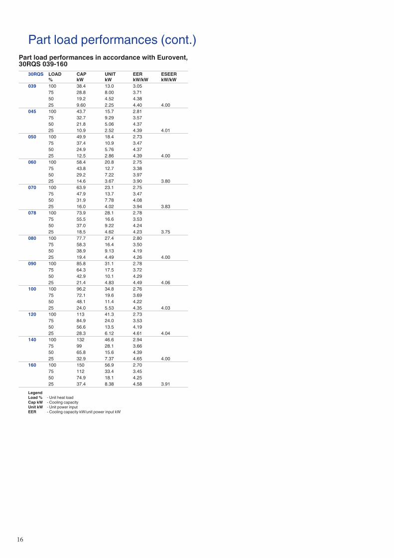
Part load performances (cont.)Part load performances in accordance with Eurovent, 30RQS 039-160
30RQS LOAD %
CAP kW
UNIT kW
EER kW/kW
ESEER kW/kW
039 100 38.4 13.0 3.0575 28.8 8.00 3.7150 19.2 4.52 4.3825 9.60 2.25 4.40 4.00
045 100 43.7 15.7 2.8175 32.7 9.29 3.5750 21.8 5.06 4.3725 10.9 2.52 4.39 4.01
050 100 49.9 18.4 2.7375 37.4 10.9 3.4750 24.9 5.76 4.3725 12.5 2.86 4.39 4.00
060 100 58.4 20.8 2.7575 43.8 12.7 3.3850 29.2 7.22 3.9725 14.6 3.67 3.90 3.80
070 100 63.9 23.1 2.7575 47.9 13.7 3.4750 31.9 7.78 4.0825 16.0 4.02 3.94 3.83
078 100 73.9 28.1 2.7875 55.5 16.6 3.5350 37.0 9.22 4.2425 18.5 4.62 4.23 3.75
080 100 77.7 27.4 2.8075 58.3 16.4 3.5050 38.9 9.13 4.1925 19.4 4.49 4.26 4.00
090 100 85.8 31.1 2.7875 64.3 17.5 3.7250 42.9 10.1 4.2925 21.4 4.83 4.49 4.06
100 100 96.2 34.8 2.7675 72.1 19.6 3.6950 48.1 11.4 4.2225 24.0 5.53 4.35 4.03
120 100 113 41.3 2.7375 84.9 24.0 3.5350 56.6 13.5 4.1925 28.3 6.12 4.61 4.04
140 100 132 46.6 2.9475 99 28.1 3.6650 65.8 15.6 4.3925 32.9 7.37 4.65 4.00
160 100 150 56.9 2.7075 112 33.4 3.4550 74.9 18.1 4.2525 37.4 8.38 4.58 3.91
Legend Load % - Unit heat load Cap kW - Cooling capacity Unit kW - Unit power input EER - Cooling capacity kW/unit power input kW
1�
Cooling capacities, 30RBS30
RBS
039-
160
Con
dens
er e
nter
ing
air t
empe
ratu
re, °
CLW
T25
3035
4045
CAP
CO
MP
UN
ITC
OO
LC
OO
LC
APC
OM
PU
NIT
CO
OL
CO
OL
CAP
CO
MP
UN
ITC
OO
LC
OO
LC
APC
OM
PU
NIT
CO
OL
CO
OL
CAP
CO
MP
UN
ITC
OO
LC
OO
L°C
kWkW
kWl/s
kPa
kWkW
kWl/s
kPa
kWkW
kWl/s
kPa
kWkW
kWl/s
kPa
kWkW
kWl/s
kPa
039
540
.610
.711
.41.
9446
.039
.011
.612
.31.
8642
.237
.212
.713
.41.
7738
.234
.914
.014
.71.
6633
.532
.315
.616
.31.
5428
.504
546
.212
.012
.92.
2056
.744
.513
.414
.32.
1253
.142
.014
.915
.82.
0047
.938
.716
.417
.31.
8441
.535
.218
.018
.91.
6835
.105
054
.514
.415
.32.
6068
.851
.915
.916
.72.
4762
.748
.717
.518
.32.
3255
.745
.019
.420
.32.
1448
.240
.821
.622
.41.
9440
.206
061
.216
.317
.12.
9269
.358
.518
.118
.92.
7863
.754
.520
.120
.92.
5955
.950
.022
.223
.02.
3847
.845
.224
.725
.52.
1539
.607
071
.019
.519
.93.
3871
.367
.321
.321
.73.
2064
.462
.823
.323
.72.
9956
.758
.025
.525
.82.
7648
.752
.527
.828
.12.
5040
.608
083
.822
.424
.13.
9980
.179
.124
.426
.23.
7771
.474
.126
.728
.53.
5362
.568
.729
.331
.23.
2753
.562
.832
.234
.22.
9944
.609
093
.924
.225
.84.
4758
.289
.826
.828
.34.
2753
.384
.229
.631
.14.
0147
.377
.932
.634
.13.
7140
.871
.035
.937
.43.
3834
.210
010
6.0
27.9
29.5
5.05
60.8
100.
630
.532
.14.
7955
.394
.333
.535
.04.
4949
.087
.436
.738
.24.
1642
.679
.740
.241
.73.
7935
.912
012
4.6
34.5
36.1
5.93
69.7
118.
137
.038
.65.
6262
.811
1.0
39.8
41.4
5.28
55.6
103.
443
.044
.54.
9248
.594
.747
.048
.54.
5140
.814
014
3.4
37.5
40.6
6.83
75.7
135.
740
.943
.96.
4768
.312
6.8
44.7
47.7
6.04
60.0
117.
048
.951
.85.
5851
.510
5.9
53.5
56.4
5.05
42.6
160
166.
545
.248
.47.
9384
.015
7.4
49.0
52.2
7.50
75.2
147.
553
.156
.37.
0366
.313
6.9
57.9
61.0
6.52
57.3
125.
363
.266
.25.
9748
.203
97
43.0
11.0
11.6
2.05
51.2
41.3
11.9
12.6
1.97
47.0
39.3
13.0
13.7
1.87
42.5
36.9
14.3
15.0
1.76
37.2
34.2
15.9
16.5
1.63
31.7
045
48.9
12.3
13.2
2.33
62.0
47.2
13.7
14.6
2.25
58.1
44.6
15.1
16.1
2.12
52.5
41.1
16.6
17.6
1.96
45.6
37.4
18.2
19.1
1.78
38.6
050
58.3
15.0
15.8
2.78
77.1
55.5
16.4
17.3
2.64
70.2
51.9
18.0
18.9
2.48
62.2
48.1
19.8
20.7
2.29
53.9
43.7
21.8
22.7
2.09
45.2
060
65.6
16.6
17.4
3.13
77.8
62.6
18.4
19.2
2.99
71.5
58.4
20.4
21.2
2.78
62.9
53.7
22.5
23.4
2.56
53.8
48.5
25.0
25.8
2.31
44.7
070
75.4
20.1
20.6
3.60
78.9
71.4
21.9
22.3
3.40
71.1
66.7
24.0
24.4
3.18
62.6
61.5
26.2
26.5
2.93
53.8
55.6
28.5
28.8
2.65
44.7
080
88.8
22.9
24.6
4.23
89.2
83.9
24.9
26.7
4.00
79.4
78.6
27.2
29.0
3.74
69.5
72.8
29.7
31.6
3.48
59.7
66.5
32.6
34.6
3.18
49.8
090
99.6
24.8
26.4
4.75
64.2
95.2
27.5
29.0
4.54
59.0
89.4
30.2
31.8
4.26
52.3
82.8
33.2
34.8
3.95
45.2
75.6
36.6
38.1
3.60
38.1
100
112.
428
.730
.35.
3667
.110
6.6
31.3
32.9
5.08
60.8
99.9
34.4
35.9
4.76
53.9
92.5
37.6
39.2
4.41
46.8
84.3
41.1
42.6
4.02
39.4
120
131.
636
.037
.66.
2876
.812
4.6
38.8
40.3
5.94
68.9
117.
041
.643
.25.
5861
.010
9.0
44.8
46.4
5.20
53.1
100.
248
.249
.74.
7845
.114
015
2.2
38.8
41.9
7.26
84.0
143.
942
.245
.36.
8775
.513
4.3
46.1
49.1
6.41
66.2
123.
950
.353
.25.
9156
.811
2.2
54.6
57.5
5.36
47.0
160
177.
246
.749
.98.
4593
.816
7.5
50.6
53.8
7.99
84.0
157.
154
.857
.97.
5074
.214
5.8
59.5
62.7
6.95
64.0
133.
564
.867
.86.
3753
.903
910
46.7
11.4
12.0
2.23
59.8
44.8
12.3
13.0
2.14
54.9
42.6
13.5
14.1
2.04
49.5
40.0
14.8
15.4
1.91
43.4
37.1
16.4
17.0
1.77
37.0
045
53.1
12.7
13.6
2.54
70.5
51.3
14.1
15.1
2.45
66.2
48.4
15.6
16.6
2.31
59.7
44.7
17.1
18.0
2.13
52.0
40.8
18.6
19.5
1.95
44.3
050
64.3
15.9
16.7
3.07
90.9
61.0
17.4
18.2
2.91
82.5
57.1
19.0
19.9
2.73
73.0
52.9
20.8
21.7
2.53
63.3
48.1
22.7
23.6
2.30
53.1
060
72.2
17.1
17.9
3.45
91.5
69.0
18.9
19.7
3.29
84.0
64.5
20.9
21.7
3.08
74.2
59.5
23.0
23.9
2.84
64.0
53.9
25.5
26.3
2.57
53.4
070
80.5
20.7
21.2
3.84
87.6
76.1
22.7
23.1
3.63
78.8
71.2
24.8
25.2
3.40
69.6
65.9
27.1
27.4
3.15
60.2
59.9
29.5
29.7
2.86
50.5
080
96.7
23.7
25.3
4.62
104.
491
.425
.727
.54.
3793
.385
.628
.029
.84.
0981
.779
.430
.532
.43.
7969
.972
.633
.335
.43.
4758
.409
010
8.5
25.9
27.4
5.18
74.4
103.
828
.530
.14.
9668
.397
.331
.332
.94.
6560
.590
.234
.435
.94.
3152
.482
.537
.739
.23.
9444
.310
012
2.3
30.0
31.6
5.84
77.1
115.
832
.734
.25.
5369
.710
8.5
35.8
37.3
5.18
61.8
100.
439
.140
.64.
8053
.691
.542
.544
.04.
3745
.112
014
2.8
37.4
39.0
6.82
88.6
135.
040
.542
.16.
4579
.312
6.5
44.0
45.6
6.04
69.9
117.
547
.749
.35.
6160
.510
7.9
51.1
52.6
5.15
51.3
140
166.
440
.443
.57.
9597
.915
6.8
44.3
47.3
7.49
87.4
146.
148
.451
.36.
9876
.513
4.6
52.5
55.5
6.43
65.4
121.
856
.959
.75.
8254
.116
019
4.2
48.5
51.7
9.28
110.
518
3.6
52.8
56.0
8.77
98.9
172.
157
.560
.68.
2287
.215
9.9
62.3
65.4
7.64
75.5
146.
567
.570
.57.
0063
.6
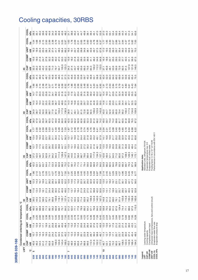
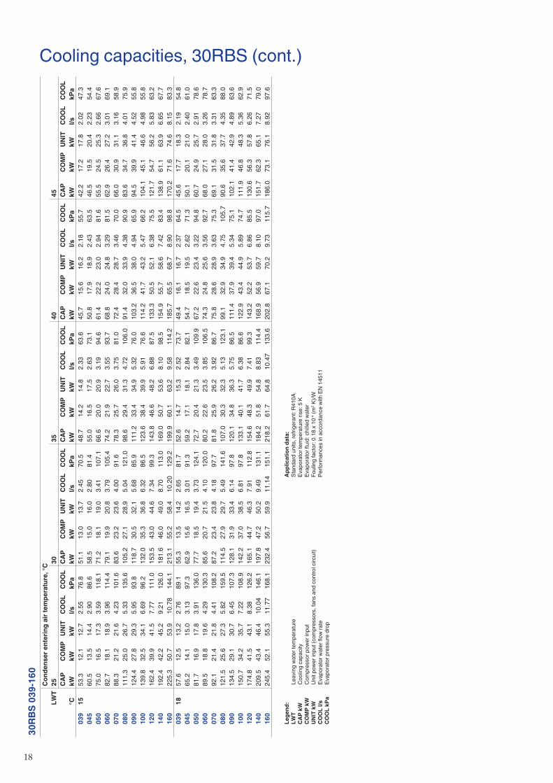
Le
gend
:
LWT
Leav
ing
wat
er te
mpe
ratu
re
CAP
kW
C
oolin
g ca
paci
ty
CO
MP
kW
Com
pres
sor p
ower
inpu
t
UN
IT k
W
Unit
pow
er in
put (
com
pres
sors
, fan
s an
d co
ntro
l circ
uit)
C
OO
L l/s
Ev
apor
ator
wat
er fl
ow ra
te
CO
OL
kPa
Evap
orat
or p
ress
ure
drop
Ap
plic
atio
n da
ta:
St
anda
rd u
nits
, ref
riger
ant:
R410
A
Evap
orat
or te
mpe
ratu
re ri
se: 5
K
Evap
orat
or fl
uid:
chi
lled
wat
er
Foul
ing
fact
or: 0
.18
x 10
-4 (m
2 K)/W
Pe
rform
ance
s in
acc
orda
nce
with
EN
145
11
18
30RB
S 03
9-16
0C
onde
nser
ent
erin
g ai
r tem
pera
ture
, °C
LWT
2530
3540
45C
APC
OM
PU
NIT
CO
OL
CO
OL
CAP
CO
MP
UN
ITC
OO
LC
OO
LC
APC
OM
PU
NIT
CO
OL
CO
OL
CAP
CO
MP
UN
ITC
OO
LC
OO
LC
APC
OM
PU
NIT
CO
OL
CO
OL
°CkW
kWkW
l/skP
akW
kWkW
l/skP
akW
kWkW
l/skP
akW
kWkW
l/skP
akW
kWkW
l/skP
a03
915
53.3
12.1
12.7
2.55
76.8
51.1
13.0
13.7
2.45
70.5
48.7
14.2
14.8
2.33
63.6
45.7
15.6
16.2
2.18
55.7
42.2
17.2
17.8
2.02
47.3
045
60.5
13.5
14.4
2.90
86.6
58.5
15.0
16.0
2.80
81.4
55.0
16.5
17.5
2.63
73.1
50.8
17.9
18.9
2.43
63.5
46.5
19.5
20.4
2.23
54.4
050
75.0
16.5
17.3
3.59
118.
171
.218
.119
.03.
4110
7.1
66.6
20.0
20.9
3.19
94.6
61.4
22.2
23.0
2.94
81.6
55.5
24.5
25.3
2.66
67.6
060
82.7
18.1
18.9
3.96
114.
479
.119
.920
.83.
7910
5.4
74.2
21.9
22.7
3.55
93.7
68.8
24.0
24.8
3.29
81.5
62.9
26.4
27.2
3.01
69.1
070
88.3
21.2
21.6
4.23
101.
683
.623
.223
.64.
0091
.678
.325
.726
.03.
7581
.072
.428
.428
.73.
4670
.066
.030
.931
.13.
1658
.908
011
1.3
25.0
26.7
5.33
135.
610
5.2
27.1
28.9
5.04
121.
098
.629
.431
.34.
7210
6.0
91.4
32.0
33.9
4.38
90.9
83.6
34.7
36.8
4.01
75.9
090
124.
427
.829
.35.
9593
.811
8.7
30.5
32.1
5.68
85.9
111.
233
.434
.95.
3276
.010
3.2
36.5
38.0
4.94
65.9
94.5
39.9
41.4
4.52
55.8
100
139.
832
.534
.16.
6996
.213
2.0
35.3
36.8
6.32
86.5
123.
638
.439
.95.
9176
.611
4.2
41.7
43.2
5.47
66.2
104.
145
.146
.64.
9855
.812
016
2.4
39.9
41.5
7.77
111.
015
3.5
43.0
44.6
7.34
99.3
143.
846
.648
.26.
8887
.513
3.3
50.5
52.1
6.38
75.5
121.
754
.756
.25.
8363
.214
019
2.4
42.2
45.2
9.21
126.
018
1.6
46.0
49.0
8.70
113.
016
9.0
50.7
53.6
8.10
98.5
154.
955
.758
.67.
4283
.413
8.9
61.1
63.9
6.65
67.7
160
225.
350
.753
.910
.78
144.
121
3.1
55.2
58.4
10.2
012
9.2
199.
960
.163
.29.
5811
4.2
185.
765
.568
.78.
9098
.817
0.2
71.6
74.6
8.15
83.3
039
1857
.612
.513
.22.
7689
.155
.313
.514
.22.
6581
.752
.614
.715
.32.
5273
.749
.416
.116
.72.
3764
.545
.617
.718
.32.
1954
.804
565
.214
.115
.03.
1397
.362
.915
.616
.53.
0191
.359
.217
.118
.12.
8482
.154
.718
.519
.52.
6271
.350
.120
.121
.02.
4061
.005
081
.716
.917
.83.
9113
6.0
77.7
18.5
19.4
3.73
124.
172
.720
.421
.33.
4910
9.9
67.2
22.6
23.4
3.22
94.8
60.7
24.9
25.7
2.91
78.6
060
89.5
18.8
19.6
4.29
130.
385
.620
.721
.54.
1012
0.0
80.2
22.6
23.5
3.85
106.
574
.324
.825
.63.
5692
.768
.027
.128
.03.
2678
.707
092
.121
.421
.84.
4110
8.2
87.2
23.4
23.8
4.18
97.7
81.8
25.9
26.2
3.92
86.7
75.8
28.6
28.9
3.63
75.3
69.1
31.5
31.8
3.31
63.3
080
121.
525
.627
.35.
8215
9.5
114.
527
.929
.75.
4914
1.6
107.
030
.332
.35.
1312
3.1
99.1
32.9
34.9
4.75
105.
790
.635
.637
.74.
3588
.009
013
4.5
29.1
30.7
6.45
107.
312
8.1
31.9
33.4
6.14
97.8
120.
134
.836
.35.
7586
.511
1.4
37.9
39.4
5.34
75.1
102.
141
.442
.94.
8963
.610
015
0.7
34.2
35.7
7.22
108.
914
2.2
37.0
38.5
6.81
97.8
133.
140
.141
.76.
3886
.612
2.9
43.4
44.9
5.89
74.7
111.
946
.848
.35.
3662
.912
017
4.8
41.5
43.1
8.38
126.
216
5.1
44.7
46.3
7.91
112.
815
4.6
48.3
49.9
7.41
99.3
143.
252
.253
.76.
8685
.513
0.6
56.3
57.8
6.26
71.5
140
209.
543
.446
.410
.04
146.
119
7.8
47.2
50.2
9.49
131.
118
4.2
51.8
54.8
8.83
114.
416
8.9
56.9
59.7
8.10
97.0
151.
762
.365
.17.
2779
.016
024
5.4
52.1
55.3
11.7
716
8.1
232.
456
.759
.911
.14
151.
121
8.2
61.7
64.8
10.4
713
3.6
202.
867
.170
.29.
7311
5.7
186.
073
.176
.18.
9297
.6
Cooling capacities, 30RBS (cont.)
Le
gend
:
LWT
Leav
ing
wat
er te
mpe
ratu
re
CAP
kW
C
oolin
g ca
paci
ty
CO
MP
kW
Com
pres
sor p
ower
inpu
t
UN
IT k
W
Unit
pow
er in
put (
com
pres
sors
, fan
s an
d co
ntro
l circ
uit)
C
OO
L l/s
Ev
apor
ator
wat
er fl
ow ra
te
CO
OL
kPa
Evap
orat
or p
ress
ure
drop
Ap
plic
atio
n da
ta:
St
anda
rd u
nits
, ref
riger
ant:
R410
A
Evap
orat
or te
mpe
ratu
re ri
se: 5
K
Evap
orat
or fl
uid:
chi
lled
wat
er
Foul
ing
fact
or: 0
.18
x 10
-4 (m
2 K)/W
Pe
rform
ance
s in
acc
orda
nce
with
EN
145
11
19
Cooling capacities, 30RQS30
RQS
039-
160
Con
dens
er e
nter
ing
air t
empe
ratu
re, °
CLW
T25
3035
4045
CAP
CO
MP
UN
ITC
OO
LC
OO
LC
APC
OM
PU
NIT
CO
OL
CO
OL
CAP
CO
MP
UN
ITC
OO
LC
OO
LC
APC
OM
PU
NIT
CO
OL
CO
OL
CAP
CO
MP
UN
ITC
OO
LC
OO
L°C
kWkW
kWl/s
kPa
kWkW
kWl/s
kPa
kWkW
kWl/s
kPa
kWkW
kWl/s
kPa
kWkW
kWl/s
kPa
039
539
.610
.110
.81.
8942
.938
.010
.911
.71.
8139
.236
.112
.012
.81.
7235
.333
.713
.314
.11.
6030
.731
.014
.815
.61.
4825
.804
545
.011
.912
.72.
1453
.543
.413
.214
.02.
0750
.240
.914
.715
.51.
9545
.237
.716
.217
.01.
7939
.034
.117
.918
.61.
6232
.805
052
.414
.215
.02.
5051
.249
.915
.716
.42.
3846
.847
.017
.318
.12.
2441
.943
.719
.220
.02.
0836
.639
.821
.422
.11.
9030
.906
060
.915
.517
.22.
9052
.758
.217
.018
.72.
7748
.455
.018
.820
.52.
6243
.550
.920
.822
.42.
4237
.646
.322
.924
.62.
2131
.607
067
.017
.519
.13.
1965
.763
.819
.220
.83.
0460
.060
.121
.122
.72.
8653
.655
.723
.224
.82.
6546
.550
.725
.627
.12.
4239
.107
877
.921
.923
.53.
7164
.973
.923
.825
.43.
5258
.469
.425
.927
.53.
3151
.564
.628
.430
.03.
0744
.459
.231
.232
.82.
8237
.208
081
.621
.423
.03.
8947
.177
.523
.324
.83.
6942
.773
.025
.426
.93.
4738
.167
.927
.729
.23.
2433
.362
.430
.431
.92.
9728
.409
089
.823
.825
.34.
2853
.685
.826
.327
.84.
0849
.180
.529
.130
.63.
8343
.674
.332
.133
.73.
5437
.467
.435
.537
.03.
2131
.210
010
1.3
27.1
28.6
4.83
59.7
96.4
29.7
31.2
4.59
54.4
90.3
32.6
34.1
4.30
48.2
83.5
35.9
37.4
3.97
41.7
75.8
39.4
40.9
3.61
34.9
120
119.
132
.934
.45.
6766
.011
2.9
35.8
37.4
5.38
59.5
106.
139
.040
.65.
0552
.798
.642
.744
.34.
7045
.790
.547
.048
.54.
3138
.614
013
7.9
35.5
38.6
6.57
72.0
131.
538
.942
.06.
2665
.712
3.7
42.7
45.8
5.89
58.5
114.
847
.150
.25.
4650
.610
4.7
51.9
54.9
4.98
42.5
160
158.
244
.447
.57.
5378
.214
9.9
48.3
51.4
7.14
70.3
140.
852
.655
.76.
7162
.213
1.0
57.6
60.7
6.24
54.0
120.
263
.266
.35.
7245
.603
97
42.1
10.3
11.0
2.01
48.3
40.4
11.1
11.9
1.93
44.2
38.4
12.2
13.0
1.83
39.7
35.9
13.5
14.3
1.71
34.6
33.1
15.0
15.8
1.58
29.1
045
47.9
12.1
12.9
2.28
59.0
46.2
13.5
14.2
2.20
55.4
43.7
15.0
15.7
2.08
50.1
40.2
16.5
17.2
1.92
43.3
36.5
18.1
18.8
1.74
36.5
050
55.5
14.4
15.2
2.65
56.3
53.0
15.9
16.7
2.52
51.6
49.9
17.6
18.4
2.38
46.2
46.4
19.5
20.3
2.21
40.5
42.4
21.7
22.4
2.02
34.4
060
64.5
15.8
17.5
3.08
58.0
61.8
17.4
19.0
2.95
53.5
58.4
19.2
20.8
2.78
48.1
54.0
21.1
22.8
2.58
41.6
49.3
23.3
24.9
2.35
35.1
070
71.2
17.9
19.5
3.40
72.9
67.9
19.6
21.2
3.24
66.7
63.9
21.5
23.1
3.05
59.5
59.3
23.7
25.2
2.83
51.7
54.0
26.0
27.6
2.58
43.5
078
82.8
22.4
24.0
3.95
72.8
78.6
24.4
26.0
3.75
65.5
73.9
26.5
28.1
3.53
57.8
68.8
29.0
30.6
3.28
49.9
63.1
31.8
33.3
3.01
41.9
080
86.8
21.8
23.4
4.14
52.4
82.5
23.7
25.3
3.93
47.6
77.7
25.8
27.4
3.71
42.5
72.4
28.2
29.7
3.45
37.2
66.6
30.8
32.3
3.17
31.7
090
95.5
24.2
25.8
4.55
59.5
91.3
26.8
28.3
4.35
54.7
85.8
29.6
31.1
4.09
48.6
79.2
32.7
34.2
3.78
41.8
72.0
36.1
37.6
3.43
34.9
100
108.
027
.829
.35.
1566
.510
2.7
30.4
31.9
4.90
60.5
96.2
33.4
34.8
4.58
53.5
89.0
36.7
38.2
4.24
46.4
80.8
40.2
41.7
3.85
38.8
120
127.
033
.635
.16.
0674
.012
0.4
36.6
38.1
5.74
66.6
113.
239
.841
.35.
4059
.110
5.3
43.5
45.0
5.02
51.3
96.6
47.7
49.2
4.61
43.4
140
146.
736
.239
.46.
9980
.013
9.9
39.7
42.8
6.67
73.1
131.
643
.546
.66.
2765
.012
2.1
48.0
51.0
5.82
56.4
111.
452
.855
.85.
3147
.316
016
8.2
45.5
48.6
8.02
87.1
159.
449
.452
.67.
6078
.414
9.7
53.8
56.9
7.14
69.5
139.
358
.861
.96.
6460
.212
7.9
64.4
67.4
6.10
50.9
039
1046
.110
.611
.42.
2057
.244
.211
.512
.32.
1152
.442
.012
.513
.32.
0147
.239
.313
.814
.61.
8841
.136
.315
.316
.11.
7334
.804
552
.412
.413
.22.
5068
.150
.713
.814
.62.
4264
.147
.915
.316
.12.
2958
.144
.216
.817
.62.
1150
.340
.218
.419
.21.
9242
.605
060
.414
.915
.72.
8864
.657
.616
.417
.22.
7559
.354
.318
.118
.92.
5953
.250
.620
.020
.82.
4246
.746
.422
.222
.92.
2139
.806
070
.516
.418
.03.
3767
.467
.617
.919
.63.
2362
.363
.919
.821
.53.
0556
.059
.221
.823
.42.
8348
.654
.123
.925
.52.
5841
.107
078
.018
.520
.23.
7284
.974
.420
.221
.93.
5577
.770
.022
.123
.73.
3469
.464
.924
.325
.93.
1060
.359
.226
.728
.32.
8350
.807
890
.823
.224
.84.
3386
.386
.225
.226
.84.
1277
.781
.127
.429
.03.
8768
.675
.529
.931
.53.
6059
.369
.332
.734
.23.
3149
.808
095
.122
.524
.04.
5461
.390
.424
.426
.04.
3255
.785
.226
.628
.14.
0749
.879
.428
.930
.43.
7943
.673
.131
.633
.13.
4937
.209
010
4.4
25.0
26.5
4.99
69.4
99.9
27.6
29.1
4.77
63.8
93.9
30.4
31.9
4.49
56.8
86.9
33.5
35.0
4.15
48.9
79.2
37.0
38.5
3.78
41.0
100
118.
828
.730
.25.
6777
.911
2.8
31.4
32.9
5.39
70.8
105.
434
.536
.05.
0362
.497
.537
.939
.34.
6554
.088
.641
.442
.94.
2345
.212
013
9.3
34.7
36.2
6.65
87.2
132.
237
.739
.36.
3178
.712
4.3
41.0
42.5
5.93
69.8
115.
744
.746
.25.
5260
.710
6.2
48.8
50.3
5.07
51.4
140
160.
637
.540
.67.
6793
.615
3.2
40.9
44.1
7.32
85.5
144.
144
.847
.96.
8876
.113
3.8
49.3
52.4
6.39
66.0
122.
154
.157
.25.
8355
.416
018
3.8
47.2
50.4
8.78
102.
017
4.2
51.3
54.4
8.32
91.9
163.
755
.758
.87.
8281
.415
2.4
60.7
63.8
7.28
70.7
140.
066
.369
.36.
6959
.8
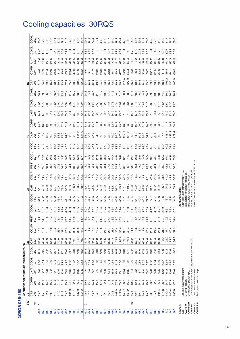
Le
gend
:
LWT
Leav
ing
wat
er te
mpe
ratu
re
CAP
kW
C
oolin
g ca
paci
ty
CO
MP
kW
Com
pres
sor p
ower
inpu
t
UN
IT k
W
Unit
pow
er in
put (
com
pres
sors
, fan
s an
d co
ntro
l circ
uit)
C
OO
L l/s
Ev
apor
ator
wat
er fl
ow ra
te
CO
OL
kPa
Evap
orat
or p
ress
ure
drop
Ap
plic
atio
n da
ta:
St
anda
rd u
nits
, ref
riger
ant:
R410
A
Evap
orat
or te
mpe
ratu
re ri
se: 5
K
Evap
orat
or fl
uid:
chi
lled
wat
er
Foul
ing
fact
or: 0
.18
x 10
-4 (m
2 K)/W
Pe
rform
ance
s in
acc
orda
nce
with
EN
145
11
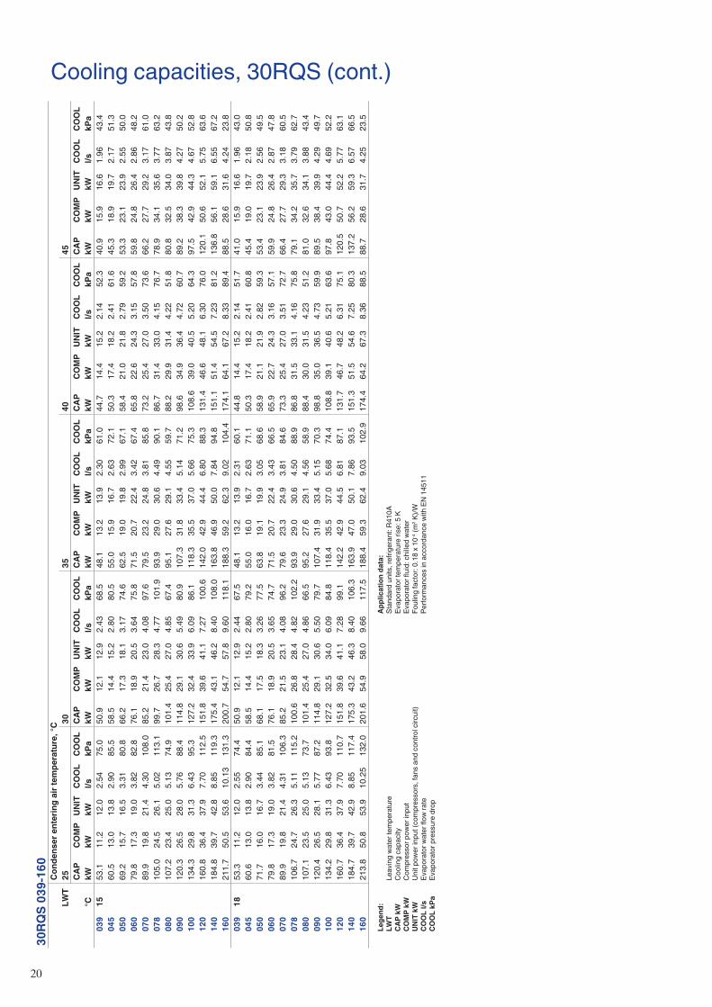
�0
Cooling capacities, 30RQS (cont.)30
RQS
039-
160
Con
dens
er e
nter
ing
air t
empe
ratu
re, °
CLW
T25
3035
4045
CAP
CO
MP
UN
ITC
OO
LC
OO
LC
APC
OM
PU
NIT
CO
OL
CO
OL
CAP
CO
MP
UN
ITC
OO
LC
OO
LC
APC
OM
PU
NIT
CO
OL
CO
OL
CAP
CO
MP
UN
ITC
OO
LC
OO
L°C
kWkW
kWl/s
kPa
kWkW
kWl/s
kPa
kWkW
kWl/s
kPa
kWkW
kWl/s
kPa
kWkW
kWl/s
kPa
039
1553
.111
.212
.02.
5475
.050
.912
.112
.92.
4368
.548
.113
.213
.92.
3061
.044
.714
.415
.22.
1452
.340
.915
.916
.61.
9643
.404
560
.513
.013
.82.
9085
.558
.514
.415
.22.
8080
.555
.015
.916
.72.
6372
.150
.317
.418
.22.
4161
.645
.318
.919
.72.
1751
.305
069
.215
.716
.53.
3180
.866
.217
.318
.13.
1774
.662
.519
.019
.82.
9967
.158
.421
.021
.82.
7959
.253
.323
.123
.92.
5550
.006
079
.817
.319
.03.
8282
.876
.118
.920
.53.
6475
.871
.520
.722
.43.
4267
.465
.822
.624
.33.
1557
.859
.824
.826
.42.
8648
.207
089
.919
.821
.44.
3010
8.0
85.2
21.4
23.0
4.08
97.6
79.5
23.2
24.8
3.81
85.8
73.2
25.4
27.0
3.50
73.6
66.2
27.7
29.2
3.17
61.0
078
105.
024
.526
.15.
0211
3.1
99.7
26.7
28.3
4.77
101.
993
.929
.030
.64.
4990
.186
.731
.433
.04.
1576
.778
.934
.135
.63.
7763
.208
010
7.2
23.4
25.0
5.13
74.9
101.
425
.427
.04.
8567
.495
.127
.629
.14.
5559
.788
.229
.931
.44.
2251
.880
.832
.534
.03.
8743
.809
012
0.3
26.5
28.0
5.76
88.4
114.
829
.130
.65.
4980
.910
7.3
31.8
33.4
5.14
71.2
98.6
34.9
36.4
4.72
60.7
89.2
38.3
39.8
4.27
50.2
100
134.
329
.831
.36.
4395
.312
7.2
32.4
33.9
6.09
86.1
118.
335
.537
.05.
6675
.310
8.6
39.0
40.5
5.20
64.3
97.5
42.9
44.3
4.67
52.8
120
160.
836
.437
.97.
7011
2.5
151.
839
.641
.17.
2710
0.6
142.
042
.944
.46.
8088
.313
1.4
46.6
48.1
6.30
76.0
120.
150
.652
.15.
7563
.614
018
4.8
39.7
42.8
8.85
119.
317
5.4
43.1
46.2
8.40
108.
016
3.8
46.9
50.0
7.84
94.8
151.
151
.454
.57.
2381
.213
6.8
56.1
59.1
6.55
67.2
160
211.
750
.553
.610
.13
131.
320
0.7
54.7
57.8
9.60
118.
118
8.3
59.2
62.3
9.02
104.
417
4.1
64.1
67.2
8.33
89.4
88.5
28.6
31.6
4.24
23.8
039
1853
.311
.212
.02.
5574
.450
.912
.112
.92.
4467
.548
.113
.213
.92.
3160
.144
.814
.415
.22.
1451
.741
.015
.916
.61.
9643
.004
560
.613
.013
.82.
9084
.458
.514
.415
.22.
8079
.255
.016
.016
.72.
6371
.150
.317
.418
.22.
4160
.845
.419
.019
.72.
1850
.805
071
.716
.016
.73.
4485
.168
.117
.518
.33.
2677
.563
.819
.119
.93.
0568
.658
.921
.121
.92.
8259
.353
.423
.123
.92.
5649
.506
079
.817
.319
.03.
8281
.576
.118
.920
.53.
6574
.771
.520
.722
.43.
4366
.565
.922
.724
.33.
1657
.159
.924
.826
.42.
8747
.807
089
.919
.821
.44.
3110
6.3
85.2
21.5
23.1
4.08
96.2
79.6
23.3
24.9
3.81
84.6
73.3
25.4
27.0
3.51
72.7
66.4
27.7
29.3
3.18
60.5
078
106.
724
.726
.35.
1111
5.2
100.
626
.828
.44.
8210
2.2
93.9
29.0
30.6
4.50
88.9
86.8
31.5
33.1
4.16
75.8
79.1
34.2
35.7
3.79
62.7
080
107.
123
.525
.05.
1373
.710
1.4
25.4
27.0
4.86
66.5
95.2
27.6
29.1
4.56
58.9
88.4
30.0
31.5
4.23
51.2
81.0
32.6
34.1
3.88
43.4
090
120.
426
.528
.15.
7787
.211
4.8
29.1
30.6
5.50
79.7
107.
431
.933
.45.
1570
.398
.835
.036
.54.
7359
.989
.538
.439
.94.
2949
.710
013
4.2
29.8
31.3
6.43
93.8
127.
232
.534
.06.
0984
.811
8.4
35.5
37.0
5.68
74.4
108.
839
.140
.65.
2163
.697
.843
.044
.44.
6952
.212
016
0.7
36.4
37.9
7.70
110.
715
1.8
39.6
41.1
7.28
99.1
142.
242
.944
.56.
8187
.113
1.7
46.7
48.2
6.31
75.1
120.
550
.752
.25.
7763
.114
018
4.7
39.7
42.9
8.85
117.
417
5.3
43.2
46.3
8.40
106.
316
3.9
47.0
50.1
7.86
93.5
151.
351
.554
.67.
2580
.313
7.2
56.2
59.3
6.57
66.5
160
213.
850
.853
.910
.25
132.
020
1.6
54.9
58.0
9.66
117.
518
8.4
59.3
62.4
9.03
102.
917
4.4
64.2
67.3
8.36
88.5
88.7
28.6
31.7
4.25
23.5
Le
gend
:
LWT
Leav
ing
wat
er te
mpe
ratu
re
CAP
kW
C
oolin
g ca
paci
ty
CO
MP
kW
Com
pres
sor p
ower
inpu
t
UN
IT k
W
Unit
pow
er in
put (
com
pres
sors
, fan
s an
d co
ntro
l circ
uit)
C
OO
L l/s
Ev
apor
ator
wat
er fl
ow ra
te
CO
OL
kPa
Evap
orat
or p
ress
ure
drop
Ap
plic
atio
n da
ta:
St
anda
rd u
nits
, ref
riger
ant:
R410
A
Evap
orat
or te
mpe
ratu
re ri
se: 5
K
Evap
orat
or fl
uid:
chi
lled
wat
er
Foul
ing
fact
or: 0
.18
x 10
-4 (m
2 K)/W
Pe
rform
ance
s in
acc
orda
nce
with
EN
145
11
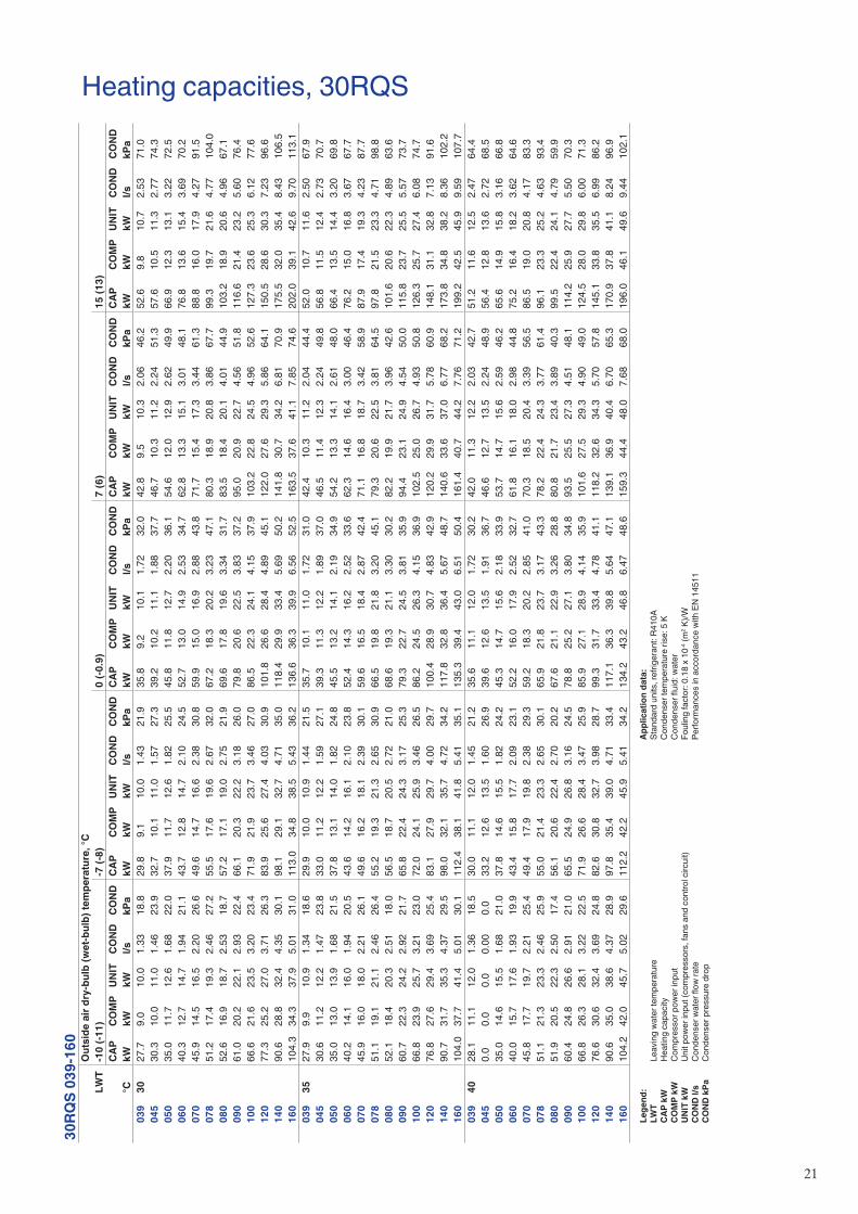
�1
Heating capacities, 30RQS30
RQS
039-
160
Out
side
air
dry-
bulb
(wet
-bul
b) te
mpe
ratu
re, °
CLW
T-1
0 (-1
1)-7
(-8)
0 (-0
.9)
7 (6
)15
(13)
CAP
CO
MP
UN
ITC
ON
DC
ON
DC
APC
OM
PU
NIT
CO
ND
CO
ND
CAP
CO
MP
UN
ITC
ON
DC
ON
DC
APC
OM
PU
NIT
CO
ND
CO
ND
CAP
CO
MP
UN
ITC
ON
DC
ON
D°C
kWkW
kWl/s
kPa
kWkW
kWl/s
kPa
kWkW
kWl/s
kPa
kWkW
kWl/s
kPa
kWkW
kWl/s
kPa
039
3027
.79.
010
.01.
3318
.829
.89.
110
.01.
4321
.935
.89.
210
.11.
7232
.042
.89.
510
.32.
0646
.252
.69.
810
.72.
5371
.004
530
.310
.011
.01.
4623
.932
.710
.111
.01.
5727
.339
.210
.211
.11.
8837
.746
.710
.311
.22.
2451
.357
.610
.511
.32.
7774
.305
035
.011
.712
.61.
6822
.037
.911
.712
.61.
8225
.545
.811
.812
.72.
2036
.154
.612
.012
.92.
6249
.966
.912
.313
.13.
2272
.506
040
.312
.714
.71.
9421
.143
.712
.814
.72.
1024
.552
.713
.014
.92.
5334
.762
.813
.315
.13.
0148
.176
.813
.615
.43.
6970
.207
045
.914
.516
.52.
2026
.649
.614
.716
.62.
3830
.859
.915
.016
.92.
8843
.871
.715
.417
.33.
4461
.388
.816
.017
.94.
2791
.507
851
.217
.419
.32.
4627
.255
.517
.619
.62.
6732
.067
.218
.320
.23.
2347
.180
.318
.920
.83.
8667
.799
.319
.721
.64.
7710
4.0
080
52.6
16.9
18.7
2.53
18.7
57.2
17.1
19.0
2.75
21.9
69.6
17.8
19.6
3.34
31.7
83.5
18.4
20.1
4.01
44.9
103.
218
.920
.64.
9667
.109
061
.020
.222
.12.
9322
.466
.120
.322
.23.
1826
.079
.820
.622
.53.
8337
.295
.020
.922
.74.
5651
.811
6.6
21.4
23.2
5.60
76.4
100
66.6
21.6
23.5
3.20
23.4
71.9
21.9
23.7
3.46
27.0
86.5
22.3
24.1
4.15
37.9
103.
222
.824
.54.
9652
.612
7.3
23.6
25.3
6.12
77.6
120
77.3
25.2
27.0
3.71
26.3
83.9
25.6
27.4
4.03
30.9
101.
826
.628
.44.
8945
.112
2.0
27.6
29.3
5.86
64.1
150.
528
.630
.37.
2396
.614
090
.628
.832
.44.
3530
.198
.129
.132
.74.
7135
.011
8.4
29.9
33.4
5.69
50.2
141.
830
.734
.26.
8170
.917
5.5
32.0
35.4
8.43
106.
516
010
4.3
34.3
37.9
5.01
31.0
113.
034
.838
.55.
4336
.213
6.6
36.3
39.9
6.56
52.5
163.
537
.641
.17.
8574
.620
2.0
39.1
42.6
9.70
113.
103
935
27.9
9.9
10.9
1.34
18.6
29.9
10.0
10.9
1.44
21.5
35.7
10.1
11.0
1.72
31.0
42.4
10.3
11.2
2.04
44.4
52.0
10.7
11.6
2.50
67.9
045
30.6
11.2
12.2
1.47
23.8
33.0
11.2
12.2
1.59
27.1
39.3
11.3
12.2
1.89
37.0
46.5
11.4
12.3
2.24
49.8
56.8
11.5
12.4
2.73
70.7
050
35.0
13.0
13.9
1.68
21.5
37.8
13.1
14.0
1.82
24.8
45.5
13.2
14.1
2.19
34.9
54.2
13.3
14.1
2.61
48.0
66.4
13.5
14.4
3.20
69.8
060
40.2
14.1
16.0
1.94
20.5
43.6
14.2
16.1
2.10
23.8
52.4
14.3
16.2
2.52
33.6
62.3
14.6
16.4
3.00
46.4
76.2
15.0
16.8
3.67
67.7
070
45.9
16.0
18.0
2.21
26.1
49.6
16.2
18.1
2.39
30.1
59.6
16.5
18.4
2.87
42.4
71.1
16.8
18.7
3.42
58.9
87.9
17.4
19.3
4.23
87.7
078
51.1
19.1
21.1
2.46
26.4
55.2
19.3
21.3
2.65
30.9
66.5
19.8
21.8
3.20
45.1
79.3
20.6
22.5
3.81
64.5
97.8
21.5
23.3
4.71
98.8
080
52.1
18.4
20.3
2.51
18.0
56.5
18.7
20.5
2.72
21.0
68.6
19.3
21.1
3.30
30.2
82.2
19.9
21.7
3.96
42.6
101.
620
.622
.34.
8963
.609
060
.722
.324
.22.
9221
.765
.822
.424
.33.
1725
.379
.322
.724
.53.
8135
.994
.423
.124
.94.
5450
.011
5.8
23.7
25.5
5.57
73.7
100
66.8
23.9
25.7
3.21
23.0
72.0
24.1
25.9
3.46
26.5
86.2
24.5
26.3
4.15
36.9
102.
525
.026
.74.
9350
.812
6.3
25.7
27.4
6.08
74.7
120
76.8
27.6
29.4
3.69
25.4
83.1
27.9
29.7
4.00
29.7
100.
428
.930
.74.
8342
.912
0.2
29.9
31.7
5.78
60.9
148.
131
.132
.87.
1391
.614
090
.731
.735
.34.
3729
.598
.032
.135
.74.
7234
.211
7.8
32.8
36.4
5.67
48.7
140.
633
.637
.06.
7768
.217
3.8
34.8
38.2
8.36
102.
216
010
4.0
37.7
41.4
5.01
30.1
112.
438
.141
.85.
4135
.113
5.3
39.4
43.0
6.51
50.4
161.
440
.744
.27.
7671
.219
9.2
42.5
45.9
9.59
107.
703
940
28.1
11.1
12.0
1.36
18.5
30.0
11.1
12.0
1.45
21.2
35.6
11.1
12.0
1.72
30.2
42.0
11.3
12.2
2.03
42.7
51.2
11.6
12.5
2.47
64.4
045
0.0
0.0
0.0
0.00
0.0
33.2
12.6
13.5
1.60
26.9
39.6
12.6
13.5
1.91
36.7
46.6
12.7
13.5
2.24
48.9
56.4
12.8
13.6
2.72
68.5
050
35.0
14.6
15.5
1.68
21.0
37.8
14.6
15.5
1.82
24.2
45.3
14.7
15.6
2.18
33.9
53.7
14.7
15.6
2.59
46.2
65.6
14.9
15.8
3.16
66.8
060
40.0
15.7
17.6
1.93
19.9
43.4
15.8
17.7
2.09
23.1
52.2
16.0
17.9
2.52
32.7
61.8
16.1
18.0
2.98
44.8
75.2
16.4
18.2
3.62
64.6
070
45.8
17.7
19.7
2.21
25.4
49.4
17.9
19.8
2.38
29.3
59.2
18.3
20.2
2.85
41.0
70.3
18.5
20.4
3.39
56.5
86.5
19.0
20.8
4.17
83.3
078
51.1
21.3
23.3
2.46
25.9
55.0
21.4
23.3
2.65
30.1
65.9
21.8
23.7
3.17
43.3
78.2
22.4
24.3
3.77
61.4
96.1
23.3
25.2
4.63
93.4
080
51.9
20.5
22.3
2.50
17.4
56.1
20.6
22.4
2.70
20.2
67.6
21.1
22.9
3.26
28.8
80.8
21.7
23.4
3.89
40.3
99.5
22.4
24.1
4.79
59.9
090
60.4
24.8
26.6
2.91
21.0
65.5
24.9
26.8
3.16
24.5
78.8
25.2
27.1
3.80
34.8
93.5
25.5
27.3
4.51
48.1
114.
225
.927
.75.
5070
.310
066
.826
.328
.13.
2222
.571
.926
.628
.43.
4725
.985
.927
.128
.94.
1435
.910
1.6
27.5
29.3
4.90
49.0
124.
528
.029
.86.
0071
.312
076
.630
.632
.43.
6924
.882
.630
.832
.73.
9828
.799
.331
.733
.44.
7841
.111
8.2
32.6
34.3
5.70
57.8
145.
133
.835
.56.
9986
.214
090
.635
.038
.64.
3728
.997
.835
.439
.04.
7133
.411
7.1
36.3
39.8
5.64
47.1
139.
136
.940
.46.
7065
.317
0.9
37.8
41.1
8.24
96.9
160
104.
242
.045
.75.
0229
.611
2.2
42.2
45.9
5.41
34.2
134.
243
.246
.86.
4748
.615
9.3
44.4
48.0
7.68
68.0
196.
046
.149
.69.
4410
2.1
Le
gend
:
LWT
Leav
ing
wat
er te
mpe
ratu
re
CAP
kW
H
eatin
g ca
paci
ty
CO
MP
kW
Com
pres
sor p
ower
inpu
t
UN
IT k
W
Unit
pow
er in
put (
com
pres
sors
, fan
s an
d co
ntro
l circ
uit)
C
ON
D l/
s C
onde
nser
wat
er fl
ow ra
te
CO
ND
kPa
C
onde
nser
pre
ssur
e dr
op
Ap
plic
atio
n da
ta:
St
anda
rd u
nits
, ref
riger
ant:
R410
A
Con
dens
er te
mpe
ratu
re ri
se: 5
K
Con
dens
er fl
uid:
wat
er
Foul
ing
fact
or: 0
.18
x 10
-4 (m
2 K)/W
Pe
rform
ance
s in
acc
orda
nce
with
EN
145
11
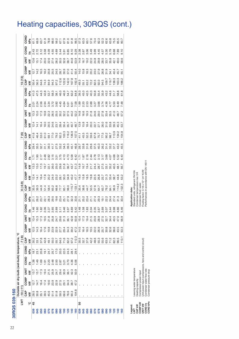
��
Heating capacities, 30RQS (cont.)30
RQS
039-
160
Out
side
air
dry-
bulb
(wet
-bul
b) te
mpe
ratu
re, °
CLW
T-1
0 (-1
1)-7
(-8)
0 (-0
.9)
7 (6
)15
(13)
CAP
CO
MP
UN
ITC
ON
DC
ON
DC
APC
OM
PU
NIT
CO
ND
CO
ND
CAP
CO
MP
UN
ITC
ON
DC
ON
DC
APC
OM
PU
NIT
CO
ND
CO
ND
CAP
CO
MP
UN
ITC
ON
DC
ON
D°C
kWkW
kWl/s
kPa
kWkW
kWl/s
kPa
kWkW
kWl/s
kPa
kWkW
kWl/s
kPa
kWkW
kWl/s
kPa
039
4528
.512
.713
.71.
3818
.730
.212
.513
.41.
4621
.135
.512
.413
.31.
7129
.441
.612
.413
.32.
0141
.050
.412
.713
.62.
4361
.104
530
.814
.715
.71.
4923
.133
.114
.315
.31.
6026
.239
.314
.115
.01.
9035
.546
.414
.115
.02.
2447
.556
.314
.215
.12.
7266
.905
035
.116
.417
.31.
6920
.837
.816
.417
.31.
8223
.744
.916
.417
.32.
1732
.753
.016
.417
.32.
5644
.364
.616
.517
.43.
1263
.706
039
.517
.419
.41.
9119
.142
.817
.619
.52.
0622
.151
.417
.819
.72.
4831
.161
.018
.019
.82.
9442
.874
.318
.220
.03.
5861
.907
045
.619
.621
.52.
2024
.749
.119
.821
.82.
3728
.358
.420
.222
.12.
8239
.369
.120
.522
.33.
3453
.784
.920
.822
.64.
0978
.807
851
.423
.925
.92.
4825
.755
.023
.925
.82.
6529
.565
.224
.026
.03.
1541
.777
.024
.626
.53.
7258
.394
.325
.527
.44.
5588
.008
051
.822
.924
.72.
5017
.055
.722
.924
.72.
6919
.666
.623
.225
.03.
2127
.579
.223
.725
.53.
8238
.197
.224
.526
.24.
6956
.209
059
.527
.529
.42.
8720
.064
.527
.729
.63.
1123
.477
.728
.129
.93.
7533
.292
.328
.430
.24.
4546
.011
2.6
28.7
30.5
5.44
67.1
100
66.6
29.1
30.9
3.21
22.0
71.6
29.4
31.3
3.46
25.1
85.1
30.0
31.8
4.10
34.5
100.
330
.432
.24.
8446
.912
2.6
30.9
32.6
5.91
67.9
120
76.6
34.3
36.1
3.70
24.3
82.2
34.3
36.1
3.97
27.9
98.0
34.9
36.7
4.73
39.3
116.
235
.737
.55.
6154
.714
2.0
37.0
38.7
6.85
81.0
140
90.3
38.7
42.3
4.36
28.1
97.2
39.2
42.8
4.69
32.3
115.
740
.243
.75.
5845
.113
6.9
40.7
44.2
6.61
62.2
167.
841
.444
.88.
1091
.816
010
4.8
47.2
50.9
5.06
29.4
112.
347
.250
.85.
4233
.613
3.1
47.7
51.3
6.42
46.8
157.
048
.752
.27.
5864
.819
2.4
50.4
53.9
9.29
96.5
039
50-
--
--
30.5
14.5
15.4
1.48
21.1
35.4
14.0
14.9
1.71
28.7
41.1
13.9
14.8
1.99
39.3
49.3
14.0
14.9
2.38
57.3
045
--
--
-32
.716
.417
.31.
5825
.238
.615
.816
.71.
8733
.845
.515
.816
.62.
2045
.055
.115
.816
.72.
6763
.305
0-
--
--
37.9
18.5
19.4
1.83
23.4
44.7
18.5
19.4
2.16
31.8
52.3
18.4
19.3
2.53
42.5
63.2
18.3
19.2
3.06
60.1
060
--
--
-42
.219
.521
.52.
0421
.150
.519
.821
.72.
4429
.659
.620
.021
.82.
8840
.372
.220
.222
.03.
4957
.607
0-
--
--
48.6
22.0
23.9
2.35
27.4
57.6
22.5
24.4
2.78
37.5
67.8
22.7
24.6
3.27
50.8
82.5
23.0
24.8
3.99
73.4
078
--
--
-55
.326
.928
.92.
6729
.364
.726
.828
.73.
1340
.375
.727
.129
.03.
6655
.492
.027
.929
.84.
4582
.308
0-
--
--
55.6
25.7
27.5
2.69
19.1
65.7
25.7
27.5
3.17
26.2
77.5
26.0
27.8
3.74
35.9
94.5
26.8
28.5
4.57
52.3
090
--
--
-63
.530
.832
.73.
0722
.276
.231
.333
.13.
6831
.490
.231
.633
.44.
3643
.210
9.7
31.9
33.7
5.30
62.6
100
--
--
-71
.232
.634
.43.
4424
.484
.133
.435
.24.
0733
.298
.733
.835
.54.
7744
.611
9.7
34.1
35.8
5.79
63.8
120
--
--
-82
.338
.640
.53.
9827
.496
.938
.740
.54.
6837
.711
3.9
39.3
41.0
5.50
51.7
138.
340
.442
.16.
6875
.514
0-
--
--
96.5
43.5
47.0
4.66
31.3
114.
244
.648
.15.
5243
.213
4.2
45.3
48.7
6.49
58.8
163.
345
.749
.07.
8985
.516
0-
--
--
113.
153
.356
.95.
4633
.413
2.3
53.2
56.7
6.40
45.5
154.
853
.757
.27.
4861
.818
8.2
55.1
58.6
9.10
90.7
Le
gend
:
LWT
Leav
ing
wat
er te
mpe
ratu
re
CAP
kW
H
eatin
g ca
paci
ty
CO
MP
kW
Com
pres
sor p
ower
inpu
t
UN
IT k
W
Unit
pow
er in
put (
com
pres
sors
, fan
s an
d co
ntro
l circ
uit)
C
ON
D l/
s C
onde
nser
wat
er fl
ow ra
te
CO
ND
kPa
C
onde
nser
pre
ssur
e dr
op
Ap
plic
atio
n da
ta:
St
anda
rd u
nits
, ref
riger
ant:
R410
A
Con
dens
er te
mpe
ratu
re ri
se: 5
K
Con
dens
er fl
uid:
wat
er
Foul
ing
fact
or: 0
.18
x 10
-4 (m
2 K)/W
Pe
rform
ance
s in
acc
orda
nce
with
EN
145
11
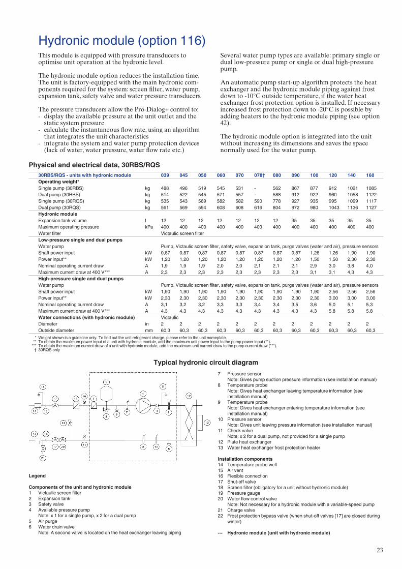
�3
Hydronic module (option 116)
Typical hydronic circuit diagram
This module is equipped with pressure transducers to optimise unit operation at the hydronic level.
The hydronic module option reduces the installation time. The unit is factory-equipped with the main hydronic com-ponents required for the system: screen filter, water pump, expansion tank, safety valve and water pressure transducers.
The pressure transducers allow the Pro-Dialog+ control to:display the available pressure at the unit outlet and the static system pressurecalculate the instantaneous flow rate, using an algorithm that integrates the unit characteristicsintegrate the system and water pump protection devices (lack of water, water pressure, water flow rate etc.)
-
-
-
Legend
Components of the unit and hydronic module1 Victaulic screen filter2 Expansion tank3 Safety valve4 Available pressure pump Note: x 1 for a single pump, x 2 for a dual pump5 Air purge6 Water drain valve Note: A second valve is located on the heat exchanger leaving piping
Physical and electrical data, 30RBS/RQS30RBS/RQS - units with hydronic module 039 045 050 060 070 078† 080 090 100 120 140 160Operating weight*Single pump (30RBS) kg 488 496 519 545 531 - 562 867 877 912 1021 1085Dual pump (30RBS) kg 514 522 545 571 557 - 588 912 922 960 1058 1122Single pump (30RQS) kg 535 543 569 582 582 590 778 927 935 995 1099 1117Dual pump (30RQS) kg 561 569 594 608 608 616 804 972 980 1043 1136 1127Hydronic module Expansion tank volume l 12 12 12 12 12 12 12 35 35 35 35 35Maximum operating pressure kPa 400 400 400 400 400 400 400 400 400 400 400 400Water filter Victaulic screen filterLow-pressure single and dual pumpsWater pump Pump, Victaulic screen filter, safety valve, expansion tank, purge valves (water and air), pressure sensorsShaft power input kW 0,87 0,87 0,87 0,87 0,87 0,87 0,87 0,87 1,26 1,26 1,90 1,90Power input** kW 1,20 1,20 1,20 1,20 1,20 1,20 1,20 1,20 1,50 1,50 2,30 2,30Nominal operating current draw A 1,9 1,9 1,9 2,0 2,0 2,1 2,1 2,1 2,9 3,0 3,8 4,0Maximum current draw at 400 V*** A 2,3 2,3 2,3 2,3 2,3 2,3 2,3 2,3 3,1 3,1 4,3 4,3High-pressure single and dual pumpsWater pump Pump, Victaulic screen filter, safety valve, expansion tank, purge valves (water and air), pressure sensorsShaft power input kW 1,90 1,90 1,90 1,90 1,90 1,90 1,90 1,90 1,90 2,56 2,56 2,56Power input** kW 2,30 2,30 2,30 2,30 2,30 2,30 2,30 2,30 2,30 3,00 3,00 3,00Nominal operating current draw A 3,1 3,2 3,2 3,3 3,3 3,4 3,4 3,5 3,6 5,0 5,1 5,3Maximum current draw at 400 V*** A 4,3 4,3 4,3 4,3 4,3 4,3 4,3 4,3 4,3 5,8 5,8 5,8Water connections (with hydronic module) VictaulicDiameter in 2 2 2 2 2 2 2 2 2 2 2 2Outside diameter mm 60,3 60,3 60,3 60,3 60,3 60,3 60,3 60,3 60,3 60,3 60,3 60,3
* Weight shown is a guideline only. To find out the unit refrigerant charge, please refer to the unit nameplate. ** To obtain the maximum power input of a unit with hydronic module, add the maximum unit power input to the pump power input (**). *** To obtain the maximum current draw of a unit with hydronic module, add the maximum unit current draw to the pump current draw (***). † 30RQS only
Several water pump types are available: primary single or dual low-pressure pump or single or dual high-pressure pump.
An automatic pump start-up algorithm protects the heat exchanger and the hydronic module piping against frost down to -10°C outside temperature, if the water heat exchanger frost protection option is installed. If necessary increased frost protection down to -�0°C is possible by adding heaters to the hydronic module piping (see option 4�).
The hydronic module option is integrated into the unit without increasing its dimensions and saves the space normally used for the water pump.
7 Pressure sensor Note: Gives pump suction pressure information (see installation manual)8 Temperature probe Note: Gives heat exchanger leaving temperature information (see
installation manual)9 Temperature probe Note: Gives heat exchanger entering temperature information (see
installation manual)10 Pressure sensor Note: Gives unit leaving pressure information (see installation manual) 11 Check valve Note: x 2 for a dual pump, not provided for a single pump12 Plate heat exchanger13 Water heat exchanger frost protection heater
Installation components14 Temperature probe well15 Air vent16 Flexible connection17 Shut-off valve18 Screen filter (obligatory for a unit without hydronic module)19 Pressure gauge20 Water flow control valve Note: Not necessary for a hydronic module with a variable-speed pump21 Charge valve22 Frost protection bypass valve (when shut-off valves [17] are closed during
winter)
--- Hydronic module (unit with hydronic module)
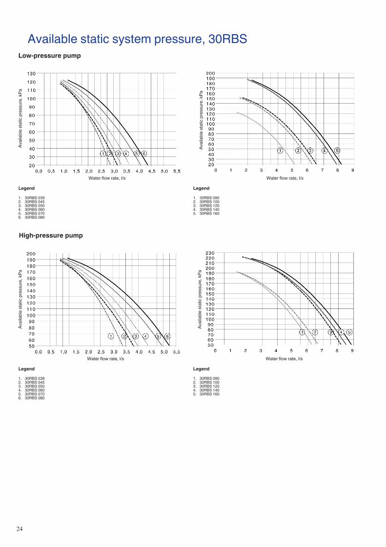
�4
Available static system pressure, 30RBSLow-pressure pump
Avai
labl
e st
atic
pre
ssur
e, k
Pa
Water flow rate, l/s
Avai
labl
e st
atic
pre
ssur
e, k
Pa
Water flow rate, l/s
Legend
1. 30RBS 039 2. 30RBS 045 3. 30RBS 0504. 30RBS 0605. 30RBS 0706. 30RBS 080
Legend
1. 30RBS 090 2. 30RBS 1003. 30RBS 1204. 30RBS 1405. 30RBS 160
High-pressure pump
Legend
1. 30RBS 039 2. 30RBS 045 3. 30RBS 0504. 30RBS 0605. 30RBS 0706. 30RBS 080
Legend
1. 30RBS 090 2. 30RBS 1003. 30RBS 1204. 30RBS 1405. 30RBS 160
Avai
labl
e st
atic
pre
ssur
e, k
Pa
Water flow rate, l/s
Avai
labl
e st
atic
pre
ssur
e, k
Pa
Water flow rate, l/s
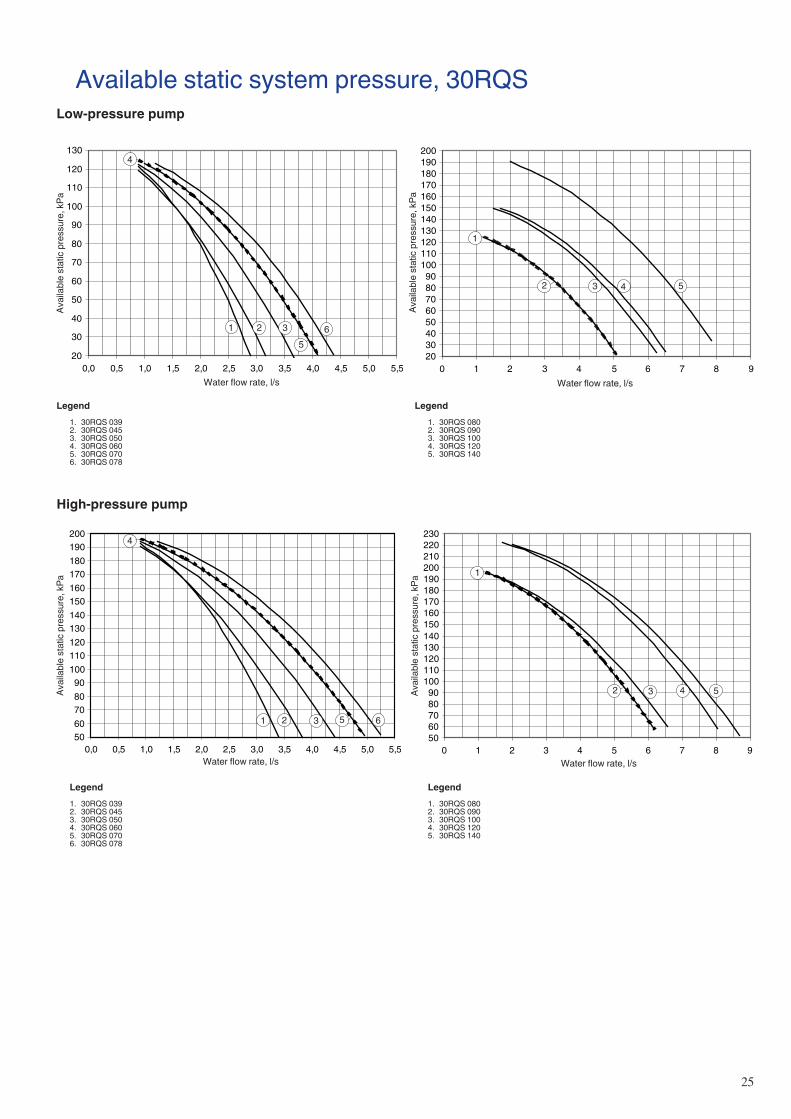
�5
Available static system pressure, 30RQSLow-pressure pump
Water flow rate, l/sWater flow rate, l/s
Water flow rate, l/sWater flow rate, l/s
High-pressure pump
20
30
40
50
60
70
80
90
100
110
120
130
0,0 0,5 1,0 1,5 2,0 2,5 3,0 3,5 4,0 4,5 5,0 5,5
65
321
4
2030405060708090
100110120130140150160170180190200
0 1 2 3 4 5 6 7 8 9
1
2 3 4 5
5060708090
100110120130140150160170180190200
0,0 0,5 1,0 1,5 2,0 2,5 3,0 3,5 4,0 4,5 5,0 5,5
4
1 2 3 5 6
5060708090
100110120130140150160170180190200210220230
0 1 2 3 4 5 6 7 8 9
1
2 3 4 5
Legend 1. 30RQS 039 2. 30RQS 045 3. 30RQS 050 4. 30RQS 060 5. 30RQS 070 6. 30RQS 078
Legend 1. 30RQS 080 2. 30RQS 090 3. 30RQS 100 4. 30RQS 120 5. 30RQS 140
Legend
1. 30RQS 039 2. 30RQS 045 3. 30RQS 050 4. 30RQS 060 5. 30RQS 070 6. 30RQS 078
Legend 1. 30RQS 080 2. 30RQS 090 3. 30RQS 100 4. 30RQS 120 5. 30RQS 140
Avai
labl
e st
atic
pre
ssur
e, k
Pa
Avai
labl
e st
atic
pre
ssur
e, k
Pa
Avai
labl
e st
atic
pre
ssur
e, k
Pa
Avai
labl
e st
atic
pre
ssur
e, k
Pa
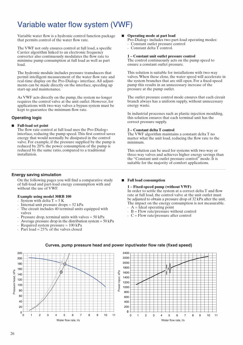
�6
Variable water flow system (VWF)Variable water flow is a hydronic control function package that permits control of the water flow rate.
The VWF not only ensures control at full load, a specific Carrier algorithm linked to an electronic frequency converter also continuously modulates the flow rate to minimise pump consumption at full load as well as part load.
The hydronic module includes pressure transducers that permit intelligent measurement of the water flow rate and real-time display on the Pro-Dialog+ interface. All adjust-ments can be made directly on the interface, speeding up start-up and maintenance.
As VWF acts directly on the pump, the system no longer requires the control valve at the unit outlet. However, for applications with two-way valves a bypass system must be kept to guarantee the minimum flow rate.
Operating logic
Full-load set pointThe flow rate control at full load uses the Pro-Dialog+ interface, reducing the pump speed. This first control saves energy that would normally be dissipated in the control valve. For example, if the pressure supplied by the pump is reduced by �0% the power consumption of the pump is reduced by the same ratio, compared to a traditional installation.
■
Operating mode at part loadPro-Dialog+ includes two part-load operating modes:
Constant outlet pressure controlConstant delta T control.
1 – Constant unit outlet pressure controlThe control continuously acts on the pump speed to ensure a constant outlet pressure.
This solution is suitable for installations with two-way valves. When these close, the water speed will accelerate in the system branches that are still open. For a fixed-speed pump this results in an unnecessary increase of the pressure at the pump outlet.
The outlet pressure control mode ensures that each circuit branch always has a uniform supply, without unnecessary energy waste.
In industrial processes such as plastic injection moulding, this solution ensures that each terminal unit has the correct pressure supply.
2 – Constant delta T controlThe VWF algorithm maintains a constant delta T no matter what the unit load, reducing the flow rate to the minimum.
This solution can be used for systems with two-way or three-way valves and achieves higher energy savings than the “Constant unit outlet pressure control” mode. It is suitable for the majority of comfort applications.
■
--
Water flow rate, l/sWater flow rate, l/s
0
20
40
60
80
100
120
140
160
180
200
220
A
C B
AA
C B
0200400600800
10001200140016001800200022002400
BC
0
BBCC
0 1 2 3 4 5 6 7 8 9 10 11 0 1 2 3 4 5 6 7 8 9 10 11
C B
Energy saving simulationOn the following pages you will find a comparative study of full-load and part-load energy consumption with and without the use of VWF.
Example using model 30RB 100System with delta T = 5 KInternal unit pressure drops = 5� kPaThe circuit includes 40 terminal units equipped with valvesPressure drop, terminal units with valves = 50 kPaAverage pressure drop in the distribution system = 50 kPaRequired system pressure = 100 kPaPart load = �5% of the valves closed
---
----
Pow
er in
put,
kPa
Pres
sure
hea
d, k
Pa
Curves, pump pressure head and power input/water flow rate (fixed speed)
Full load consumption
1 – Fixed-speed pump (without VWF)In order to settle the system at a correct delta T and flow rate at full load, the control valve at the unit outlet must be adjusted to obtain a pressure drop of 3� kPa after the unit. The impact on the energy consumption is not measurable.
A = Ideal operating pointB = Flow rate/pressure without controlC = Flow rate/pressure after control
■
---
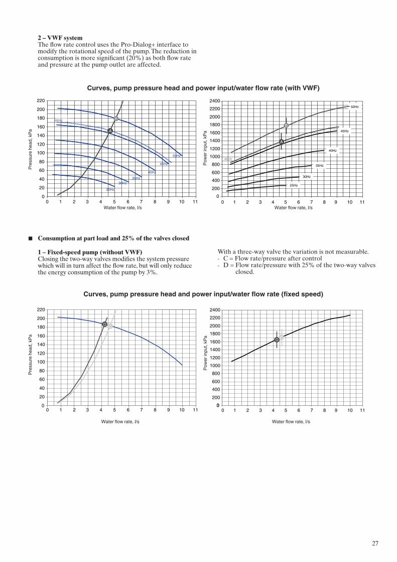
��
0200400600800
10001200140016001800200022002400
A
50Hz
45Hz
40Hz
35Hz
30Hz
25Hz
AA
50Hz
45Hz
40Hz
35Hz
30Hz
25Hz
46Hz
0
20
40
60
80
100
120
140
160
180
200
220
AAAA
50Hz
45Hz
40Hz35Hz
30Hz
25Hz
46Hz
0 1 2 3 4 5 6 7 8 9 10 11 0 1 2 3 4 5 6 7 8 9 10 11
BB
2 – VWF systemThe flow rate control uses the Pro-Dialog+ interface to modify the rotational speed of the pump. The reduction in consumption is more significant (�0%) as both flow rate and pressure at the pump outlet are affected.
Water flow rate, l/sWater flow rate, l/sPo
wer
inpu
t, kP
a
Pres
sure
hea
d, k
Pa
Curves, pump pressure head and power input/water flow rate (with VWF)
0200400600800
10001200140016001800200022002400
CD
0
CCDD
0
20
40
60
80
100
120
140
160
180
200
220
CD CCDD
0 1 2 3 4 5 6 7 8 9 10 11 0 1 2 3 4 5 6 7 8 9 10 11
1 – Fixed-speed pump (without VWF)Closing the two-way valves modifies the system pressure which will in turn affect the flow rate, but will only reduce the energy consumption of the pump by 3%.
Water flow rate, l/sWater flow rate, l/s
Pow
er in
put,
kPa
Pres
sure
hea
d, k
Pa
Curves, pump pressure head and power input/water flow rate (fixed speed)
With a three-way valve the variation is not measurable.C = Flow rate/pressure after controlD = Flow rate/pressure with �5% of the two-way valves
closed.
--
Consumption at part load and 25% of the valves closed■
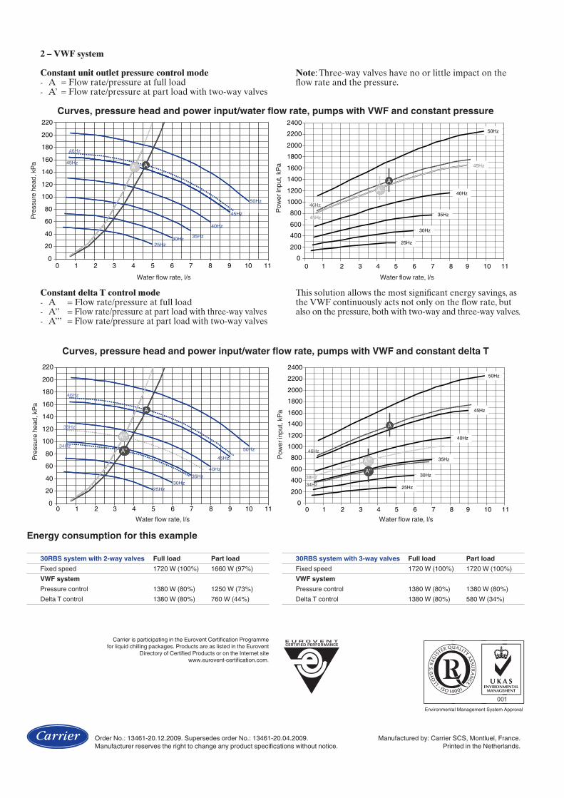
Order No.: 13461-20.12.2009. Supersedes order No.: 13461-20.04.2009. Manufactured by: Carrier SCS, Montluel, France.Manufacturer reserves the right to change any product specifications without notice. Printed in the Netherlands.
Carrier is participating in the Eurovent Certification Programme for liquid chilling packages. Products are as listed in the Eurovent
Directory of Certified Products or on the Internet site www.eurovent-certification.com.
0200400600800
10001200140016001800200022002400
A
50Hz
45Hz
40Hz
35Hz
30Hz
25Hz
46Hz
A’
45Hz
AA
50Hz
45Hz
40Hz
35Hz
30Hz
25Hz
46Hz
A’A’
45Hz
0
20
40
60
80
100
120
140
160
180
200
220
A
30Hz
A’45Hz AA
50Hz
45Hz
40Hz
35Hz25Hz
46Hz
A’A’
0 1 2 3 4 5 6 7 8 9 10 11 0 1 2 3 4 5 6 7 8 9 10 11
2 – VWF system
Constant unit outlet pressure control modeA = Flow rate/pressure at full loadA’ = Flow rate/pressure at part load with two-way valves
--
Water flow rate, l/sWater flow rate, l/sPo
wer
inpu
t, kP
a
Pres
sure
hea
d, k
Pa
Curves, pressure head and power input/water flow rate, pumps with VWF and constant pressure
Note: Three-way valves have no or little impact on the flow rate and the pressure.
0
20
40
60
80
100
120
140
160
180
200
220
A
30Hz
A’'
A’’’
AA
50Hz
45Hz
40Hz35Hz
25Hz
46Hz
34Hz
38Hz
A’'A’'
A’’’A’’’
0200400600800
10001200140016001800200022002400
A
50Hz
45Hz
40Hz
35Hz
30Hz
25Hz
46Hz
34Hz
38Hz A’'A’’’
AA
50Hz
45Hz
40Hz
35Hz
30Hz
25Hz
46Hz
34Hz38Hz
A’'A’'A’’’A’’’
0 1 2 3 4 5 6 7 8 9 10 11 0 1 2 3 4 5 6 7 8 9 10 11
Constant delta T control modeA = Flow rate/pressure at full loadA’’ = Flow rate/pressure at part load with three-way valvesA’’’ = Flow rate/pressure at part load with two-way valves
---
This solution allows the most significant energy savings, as the VWF continuously acts not only on the flow rate, but also on the pressure, both with two-way and three-way valves.
Water flow rate, l/sWater flow rate, l/s
Pow
er in
put,
kPa
Pres
sure
hea
d, k
Pa
Curves, pressure head and power input/water flow rate, pumps with VWF and constant delta T
Energy consumption for this example
30RBS system with 2-way valves Full load Part loadFixed speed 1720 W (100%) 1660 W (97%)VWF systemPressure control 1380 W (80%) 1250 W (73%) Delta T control 1380 W (80%) 760 W (44%)
30RBS system with 3-way valves Full load Part loadFixed speed 1720 W (100%) 1720 W (100%) VWF systemPressure control 1380 W (80%) 1380 W (80%)Delta T control 1380 W (80%) 580 W (34%)