Embed Size (px)
Citation preview
Wiring Diagrams
DIAGRAM INDEX
POWER SCHEMATICS
Unit 30HXA,C Voltage FigureNumber
Label DiagramNo. 30HX
076-186 ALL 1 500141206-271 ALL 2 500389
CONTROL SCHEMATICS
Unit 30HXA,C Voltage FigureNumber
Label DiagramNo. 30HX
076-18624 3 500143
115,230 4 500142
206-27124 5 500392
115,230 6 500395
COMPONENT ARRANGEMENTS
Unit 30HXA,C Voltage FigureNumber
Label DiagramNo. 30HX
076-186 ALL 7 500140206-271 ALL 8 500396
NOTE: For operating sequence, refer to Controls, Start-Up, Operation, Service, and Troubleshooting literature.
30HXA, 30HXCCondenserless and
Fluid-Cooled Chillers50/60 Hz
Manufacturer reserves the right to discontinue, or change at any time, specifications or designs without notice and without incurring obligations.Book 2Tab 5c
PC 903 Catalog No. 563-062 Printed in U.S.A. Form 30HX-1W Pg 1 8-97 Replaces: New
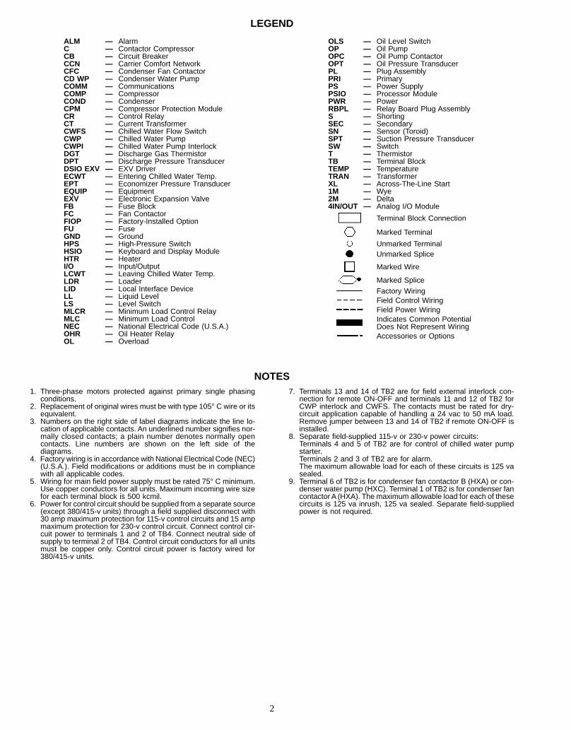
LEGEND
ALM — AlarmC — Contactor CompressorCB — Circuit BreakerCCN — Carrier Comfort NetworkCFC — Condenser Fan ContactorCD WP — Condenser Water PumpCOMM — CommunicationsCOMP — CompressorCOND — CondenserCPM — Compressor Protection ModuleCR — Control RelayCT — Current TransformerCWFS — Chilled Water Flow SwitchCWP — Chilled Water PumpCWPI — Chilled Water Pump InterlockDGT — Discharge Gas ThermistorDPT — Discharge Pressure TransducerDSIO EXV — EXV DriverECWT — Entering Chilled Water Temp.EPT — Economizer Pressure TransducerEQUIP — EquipmentEXV — Electronic Expansion ValveFB — Fuse BlockFC — Fan ContactorFIOP — Factory-Installed OptionFU — FuseGND — GroundHPS — High-Pressure SwitchHSIO — Keyboard and Display ModuleHTR — HeaterI/O — Input/OutputLCWT — Leaving Chilled Water Temp.LDR — LoaderLID — Local Interface DeviceLL — Liquid LevelLS — Level SwitchMLCR — Minimum Load Control RelayMLC — Minimum Load ControlNEC — National Electrical Code (U.S.A.)OHR — Oil Heater RelayOL — Overload
OLS — Oil Level SwitchOP — Oil PumpOPC — Oil Pump ContactorOPT — Oil Pressure TransducerPL — Plug AssemblyPRI — PrimaryPS — Power SupplyPSIO — Processor ModulePWR — PowerRBPL — Relay Board Plug AssemblyS — ShortingSEC — SecondarySN — Sensor (Toroid)SPT — Suction Pressure TransducerSW — SwitchT — ThermistorTB — Terminal BlockTEMP — TemperatureTRAN — TransformerXL — Across-The-Line Start1M — Wye2M — Delta4IN/OUT — Analog I/O Module
Terminal Block Connection
Marked Terminal
Unmarked TerminalUnmarked Splice
Marked Wire
Marked SpliceFactory WiringField Control WiringField Power WiringIndicates Common PotentialDoes Not Represent WiringAccessories or Options
NOTES1. Three-phase motors protected against primary single phasing
conditions.2. Replacement of original wires must be with type 105° C wire or its
equivalent.3. Numbers on the right side of label diagrams indicate the line lo-
cation of applicable contacts. An underlined number signifies nor-mally closed contacts; a plain number denotes normally opencontacts. Line numbers are shown on the left side of thediagrams.
4. Factory wiring is in accordance with National Electrical Code (NEC)(U.S.A.). Field modifications or additions must be in compliancewith all applicable codes.
5. Wiring for main field power supply must be rated 75° C minimum.Use copper conductors for all units. Maximum incoming wire sizefor each terminal block is 500 kcmil.
6. Power for control circuit should be supplied from a separate source(except 380/415-v units) through a field supplied disconnect with30 amp maximum protection for 115-v control circuits and 15 ampmaximum protection for 230-v control circuit. Connect control cir-cuit power to terminals 1 and 2 of TB4. Connect neutral side ofsupply to terminal 2 of TB4. Control circuit conductors for all unitsmust be copper only. Control circuit power is factory wired for380/415-v units.
7. Terminals 13 and 14 of TB2 are for field external interlock con-nection for remote ON-OFF and terminals 11 and 12 of TB2 forCWP interlock and CWFS. The contacts must be rated for dry-circuit application capable of handling a 24 vac to 50 mA load.Remove jumper between 13 and 14 of TB2 if remote ON-OFF isinstalled.
8. Separate field-supplied 115-v or 230-v power circuits:Terminals 4 and 5 of TB2 are for control of chilled water pumpstarter.Terminals 2 and 3 of TB2 are for alarm.The maximum allowable load for each of these circuits is 125 vasealed.
9. Terminal 6 of TB2 is for condenser fan contactor B (HXA) or con-denser water pump (HXC). Terminal 1 of TB2 is for condenser fancontactor A (HXA). The maximum allowable load for each of thesecircuits is 125 va inrush, 125 va sealed. Separate field-suppliedpower is not required.
2
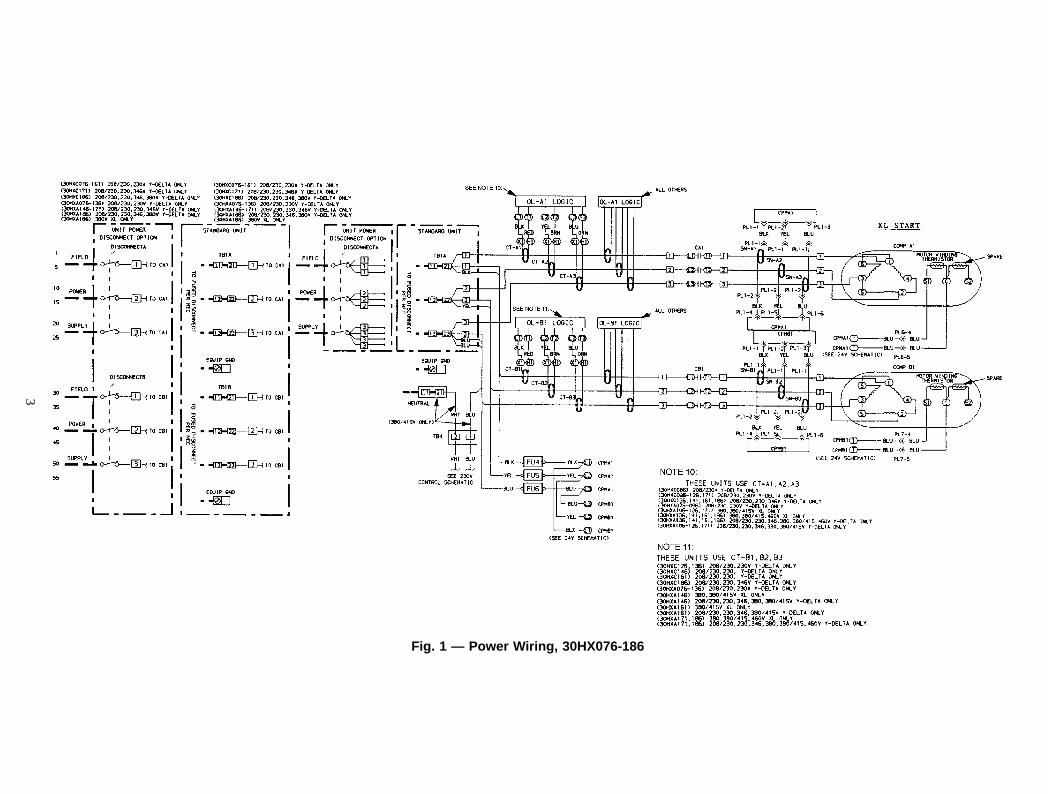
Fig. 1 — Power Wiring, 30HX076-186
3
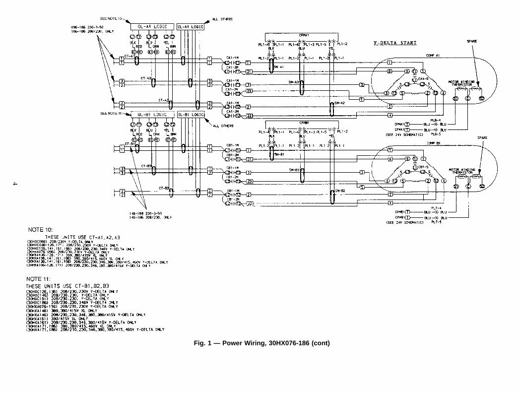
Fig. 1 — Power Wiring, 30HX076-186 (cont)
4
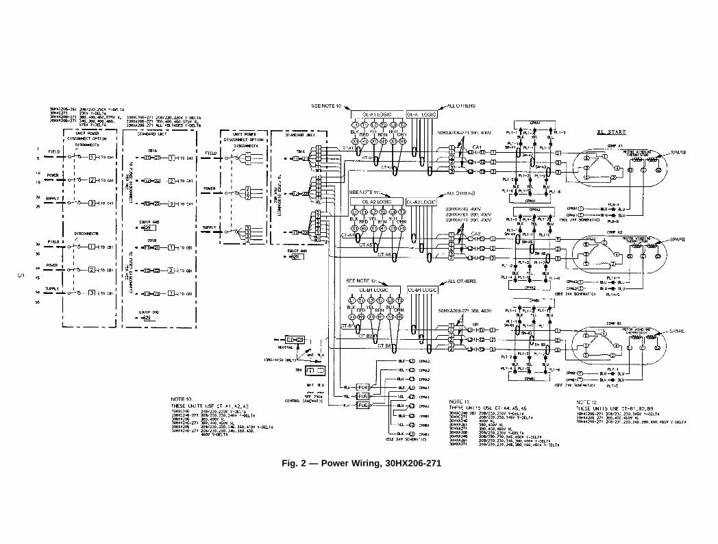
Fig. 2 — Power Wiring, 30HX206-271
5
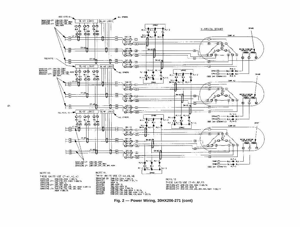
Fig. 2 — Power Wiring, 30HX206-271 (cont)
6
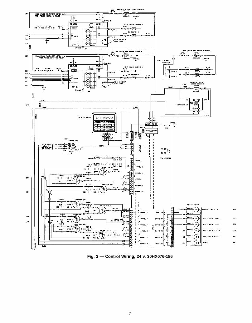
Fig. 3 — Control Wiring, 24 v, 30HX076-186
7
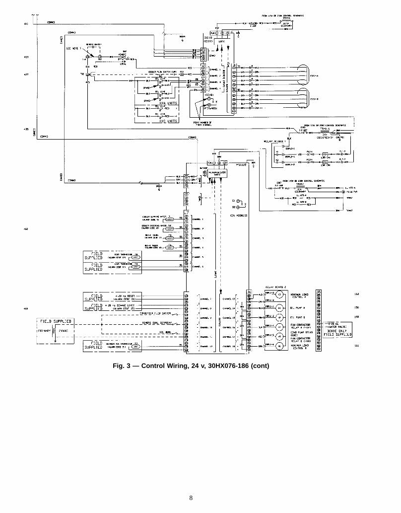
Fig. 3 — Control Wiring, 24 v, 30HX076-186 (cont)
8
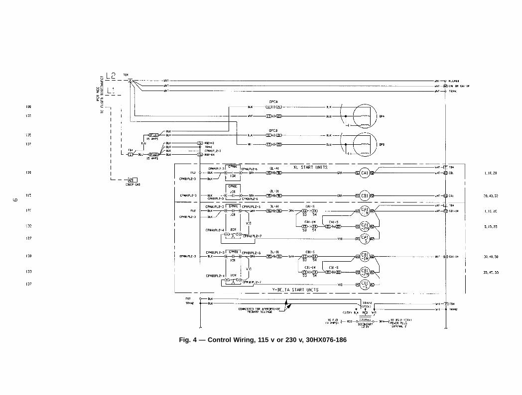
Fig. 4 — Control Wiring, 115 v or 230 v, 30HX076-186
9
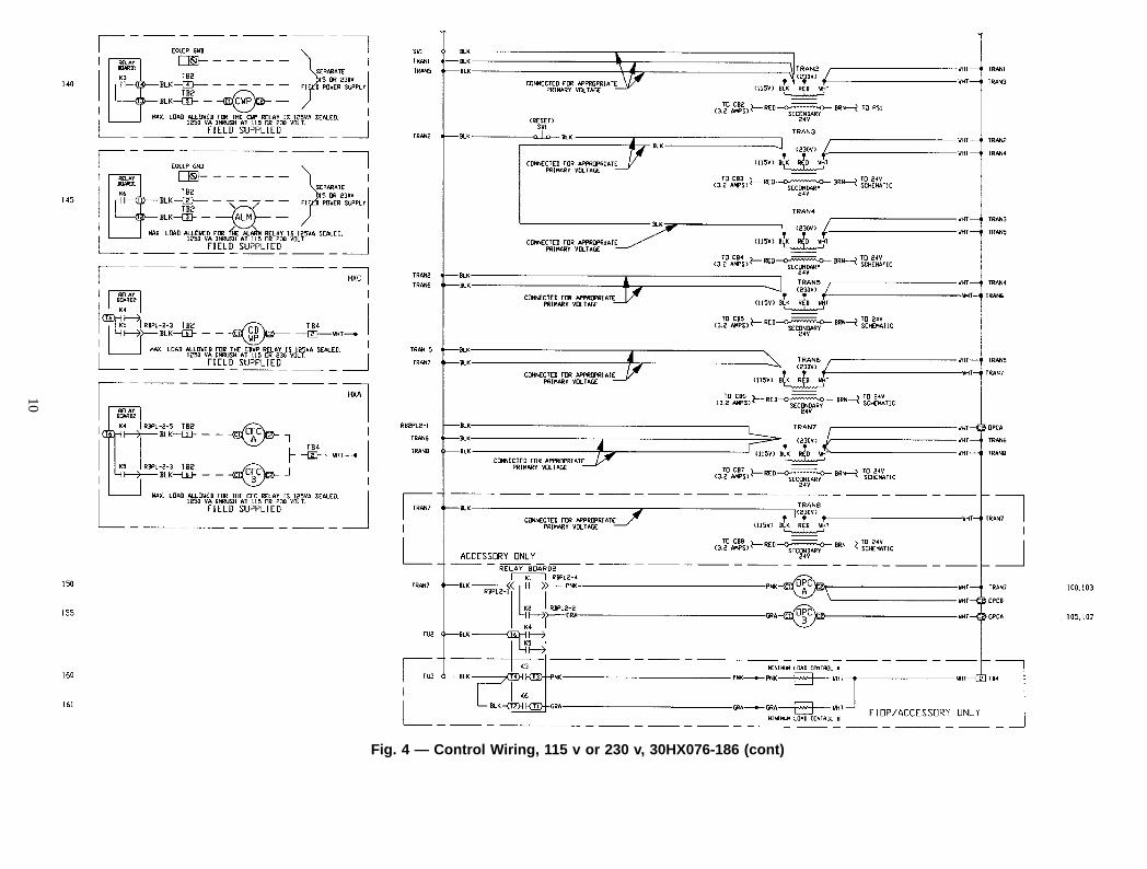
Fig. 4 — Control Wiring, 115 v or 230 v, 30HX076-186 (cont)
10
PSI
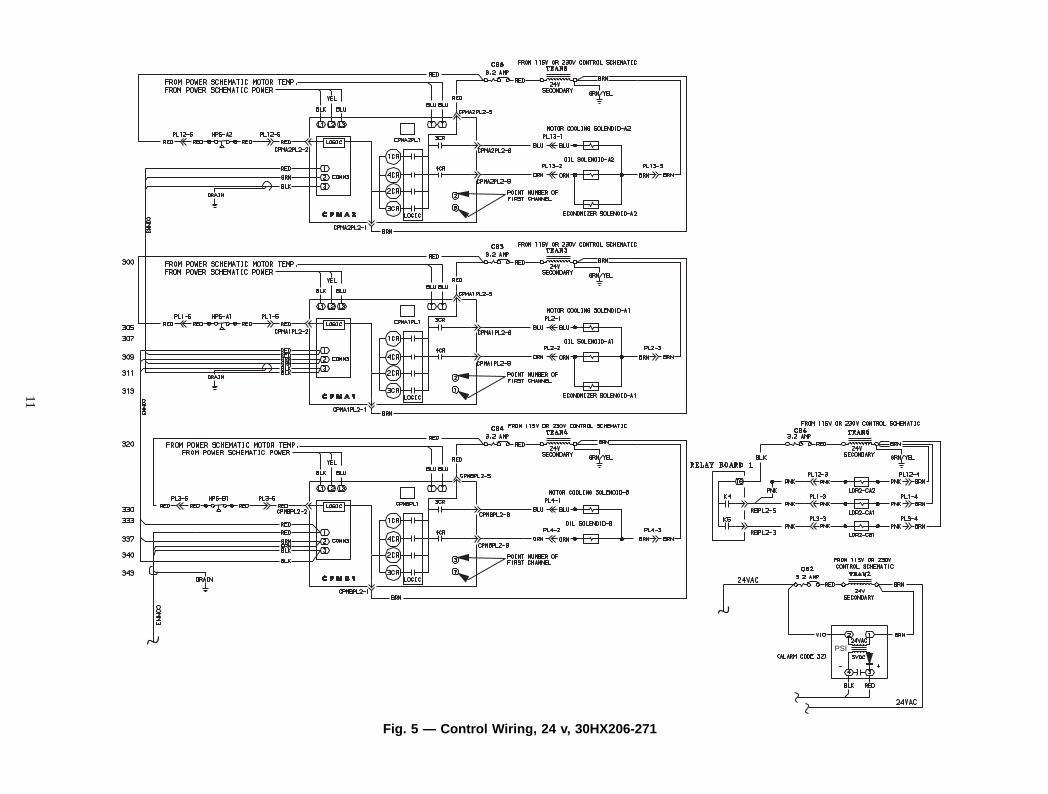
Fig. 5 — Control Wiring, 24 v, 30HX206-271
11
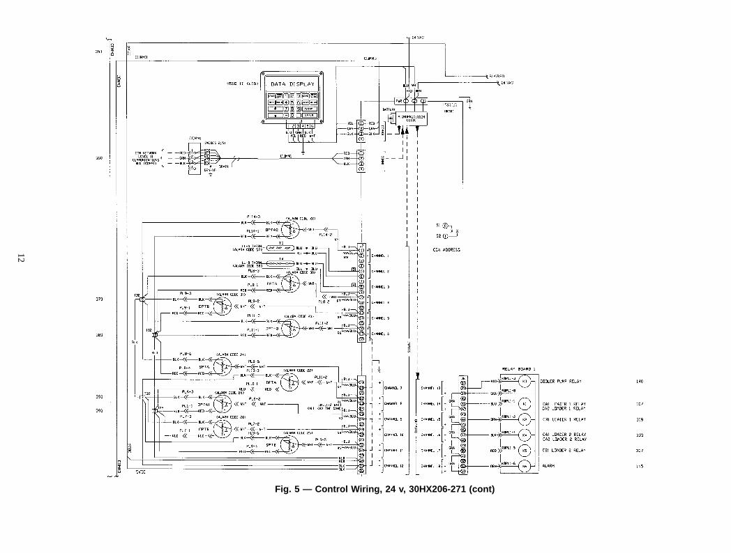
Fig. 5 — Control Wiring, 24 v, 30HX206-271 (cont)
12
SEENOTE 7
DSIO(EXV)
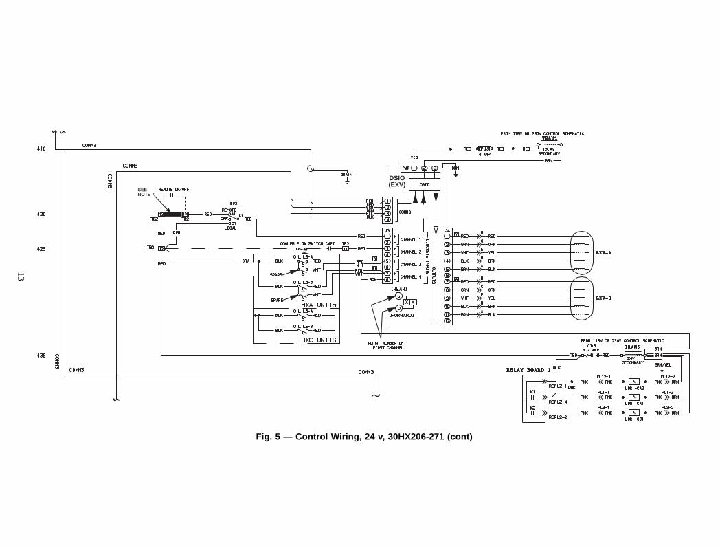
Fig. 5 — Control Wiring, 24 v, 30HX206-271 (cont)
13
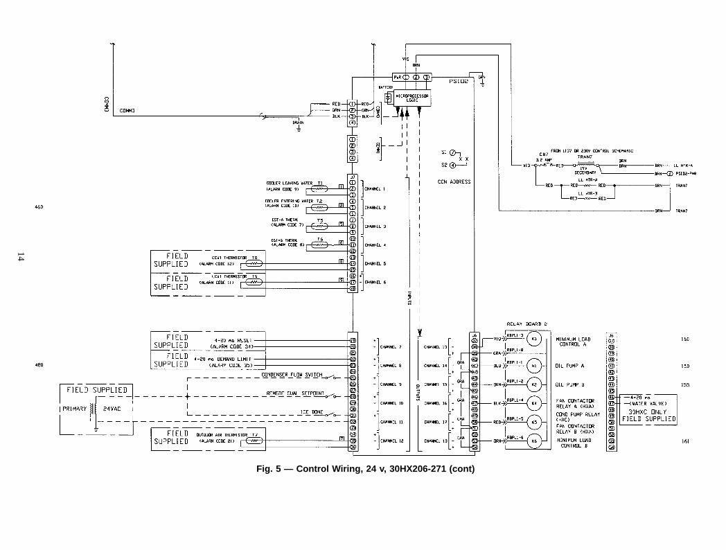
Fig. 5 — Control Wiring, 24 v, 30HX206-271 (cont)
14
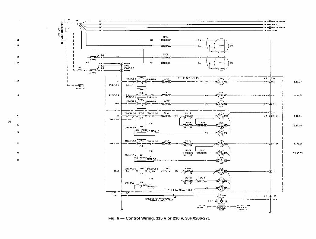
Fig. 6 — Control Wiring, 115 v or 230 v, 30HX206-271
15
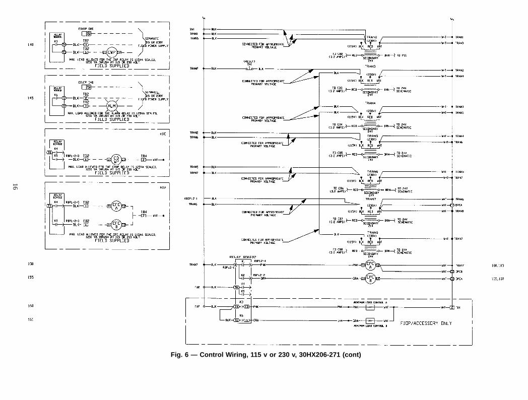
Fig. 6 — Control Wiring, 115 v or 230 v, 30HX206-271 (cont)
16
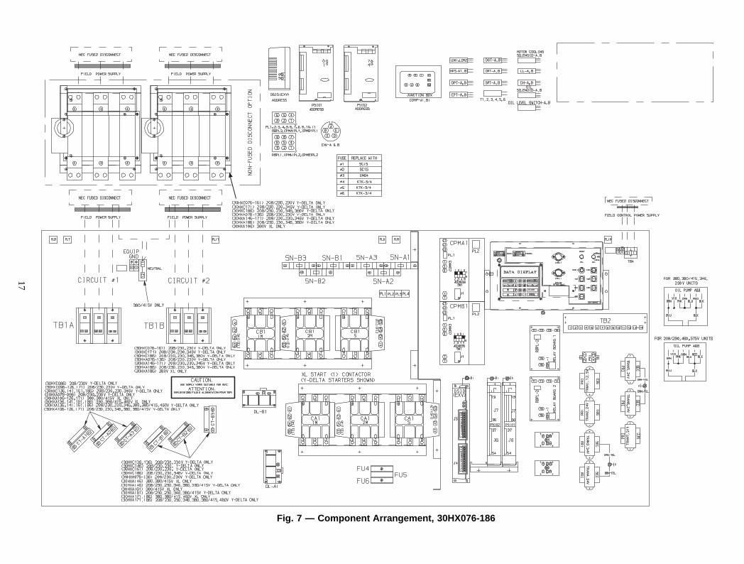
Fig. 7 — Component Arrangement, 30HX076-186
17
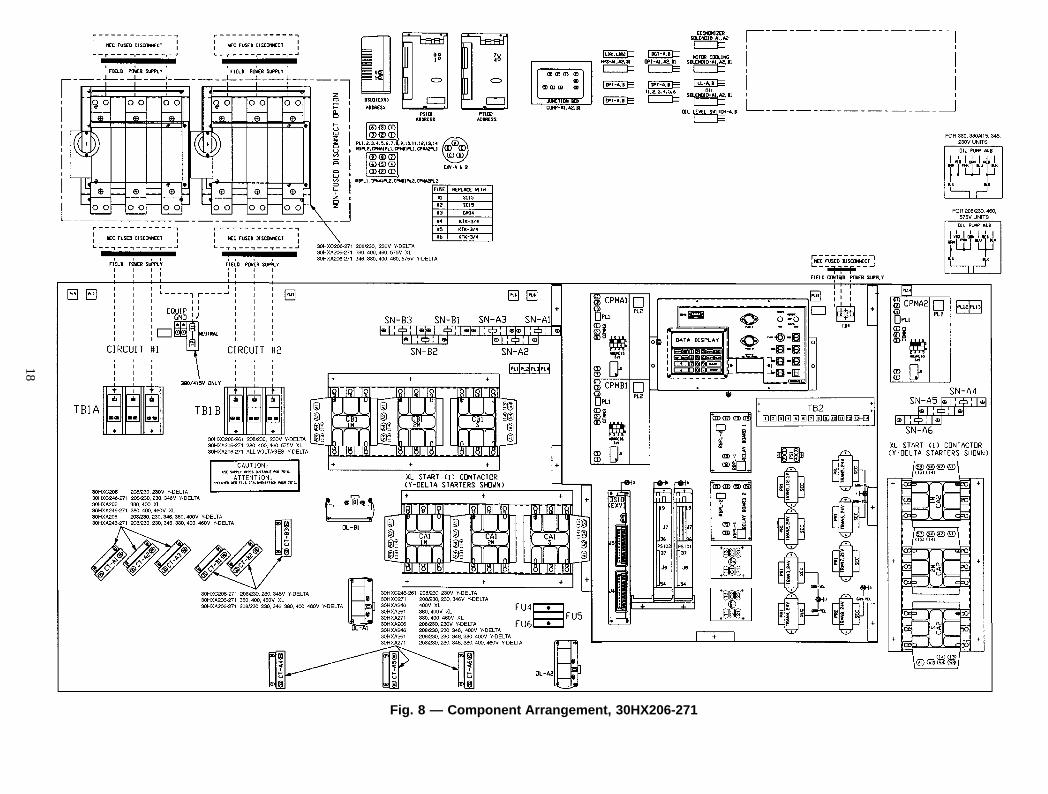
Fig. 8 — Component Arrangement, 30HX206-271
18


Copyright 1997 Carrier Corporation
Manufacturer reserves the right to discontinue, or change at any time, specifications or designs without notice and without incurring obligations.Book 2Tab 5c
PC 903 Catalog No. 563-062 Printed in U.S.A. Form 30HX-1W Pg 20 8-97 Replaces: New


![5. Wiring Diagram - Subaru Forester. Wiring Diagram A: POWER SUPPLY ROUTING SU01-04A 12 6-3 [D5A0] WIRING DIAGRAM 5. Wiring Diagram SU01-04B 13 WIRING DIAGRAM [D5A0] 6-3 5. Wiring](https://img.pdfslide.us/doc/110x75/5aa205fe7f8b9a1f6d8cac3f/5-wiring-diagram-subaru-wiring-diagram-a-power-supply-routing-su01-04a-12.jpg)


![6. Wiring Diagram - weidefamily.net coil Transmission control module ... WIRING DIAGRAM 6. Wiring Diagram. MEMO: 21 WIRING DIAGRAM ... 76 6-3 [D6R2] WIRING DIAGRAM 6](https://img.pdfslide.us/doc/110x75/5aa0cc3b7f8b9a62178ea5e7/6-wiring-diagram-coil-transmission-control-module-wiring-diagram-6-wiring.jpg)


![85RX7(50)Wiring Diagrams - wright-here.net50)Wiring_Di… · Symbol in this wiring diagram Parts index Electrical wiring schematic . . . [For 12A Engine] Electrical wiring schematic](https://img.pdfslide.us/doc/110x75/60618b736d48e7606d322842/85rx750wiring-diagrams-wright-here-50wiringdi-symbol-in-this-wiring-diagram.jpg)