Embed Size (px)
Citation preview
309967D
Instructions - Parts List
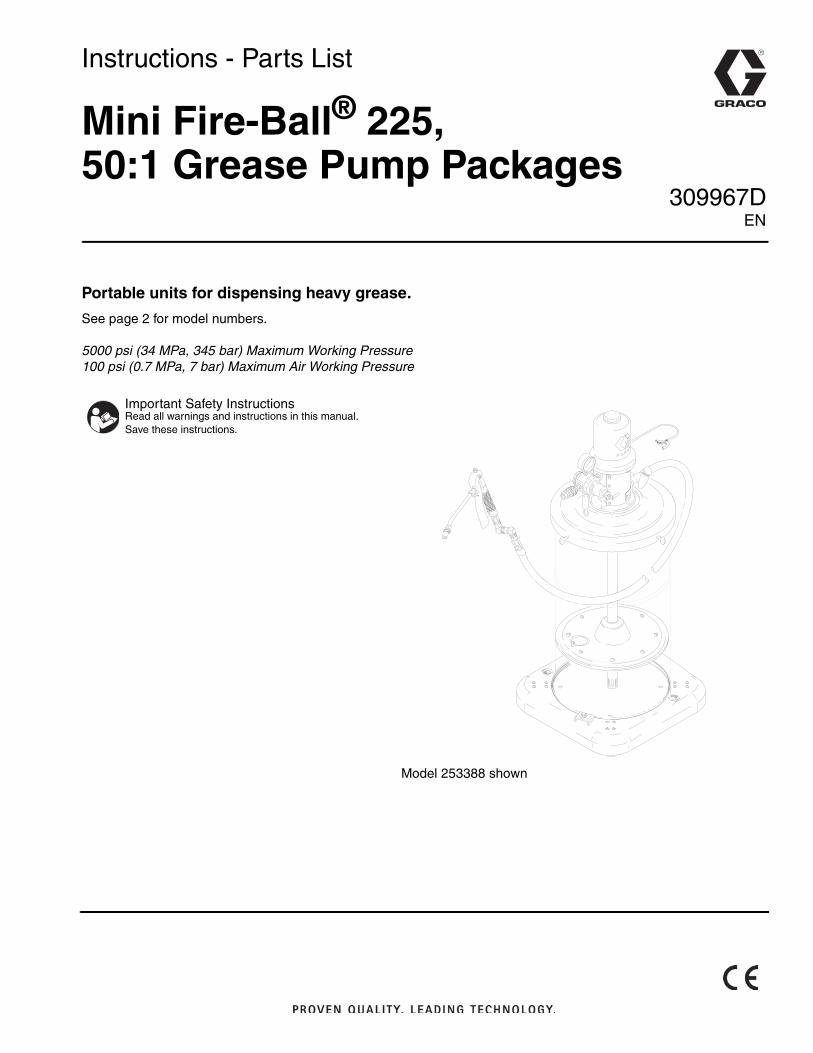
Mini Fire-Ball® 225,50:1 Grease Pump Packages
Portable units for dispensing heavy grease.
See page 2 for model numbers.
5000 psi (34 MPa, 345 bar) Maximum Working Pressure100 psi (0.7 MPa, 7 bar) Maximum Air Working Pressure
Important Safety InstructionsRead all warnings and instructions in this manual. Save these instructions.
Model 253388 shown
EN
Models
2 309967D
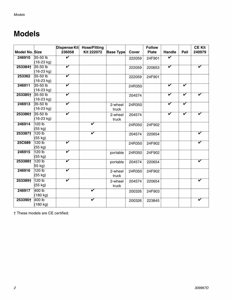
Models
† These models are CE certified.
Model No. SizeDispense Kit
236058Hose/Fitting Kit 222072 Base Type Cover
Follow Plate Handle Pail
CE Kit 240979
246910 35-50 lb (16-23 kg)
222059 24F901
253384† 35-50 lb (16-23 kg)
222059 220653
253362 35-50 lb (16-23 kg)
222059 24F901
246911 35-50 lb (16-23 kg)
24R350
253385† 35-50 lb (16-23 kg)
204574
246913 35-50 lb (16-23 kg)
2-wheel truck
24R350
253386† 35-50 lb (16-23 kg)
2-wheel truck
204574
246914 120 lb (55 kg)
24R350 24F902
253387† 120 lb (55 kg)
204574 220654
25C689 120 lb(55 kg)
24R350 24F902
246915 120 lb (55 kg)
portable 24R350 24F902
253388† 120 lb 55 kg)
portable 204574 220654
246916 120 lb (55 kg)
2-wheel truck
24R350 24F902
253389† 120 lb (55 kg)
2-wheel truck
204574 220654
246917 400 lb (180 kg)
200326 24F903
253390† 400 lb (180 kg)
200326 223845
Warnings
309967D 3
WarningsThe following general warnings are for the setup, use, grounding, maintenance, and repair of this equipment. Addi-tional, more specific warnings may be found throughout the body of this manual where applicable. Symbols appear-ing in the body of the manual refer to these general warnings. When these symbols appear throughout the manual, refer back to these pages for a description of the specific hazard.
WARNING
EQUIPMENT MISUSE HAZARD Misuse can cause death or serious injury.
• Do not operate the unit when fatigued or under the influence of drugs or alcohol.
• Do not exceed the maximum working pressure or temperature rating of the lowest rated system component. See Technical Data in all equipment manuals.
• Use fluids and solvents that are compatible with equipment wetted parts. See Technical Data in all equipment manuals. Read fluid and solvent manufacturer’s warnings. For complete information about your material, request MSDS forms from distributor or retailer.
• Check equipment daily. Repair or replace worn or damaged parts immediately with genuine Graco replacement parts only.
• Do not alter or modify equipment.
• Use equipment only for its intended purpose. Call your Graco distributor for information.
• Route hoses and cables away from traffic areas, sharp edges, moving parts, and hot surfaces.
• Do not kink or over bend hoses or use hoses to pull equipment.
• Keep children and animals away from work area.
• Comply with all applicable safety regulations.
SKIN INJECTION HAZARDHigh-pressure fluid from dispense valve, hose leaks, or ruptured components will pierce skin. This may look like just a cut, but it is a serious injury that can result in amputation. Get immediate surgical treatment.
• Do not point dispense valve at anyone or at any part of the body.
• Do not put your hand over the end of the dispense nozzle.
• Do not stop or deflect leaks with your hand, body, glove, or rag.
• Follow Pressure Relief Procedure in this manual, when you stop dispensing and before cleaning, checking, or servicing equipment.
MOVING PARTS HAZARDMoving parts can pinch or amputate fingers and other body parts.
• Keep clear of moving parts.
• Do not operate equipment with protective guards or covers removed.
• Pressurized equipment can start without warning. Before checking, moving, or servicing equipment, follow the Pressure Relief Procedure in this manual. Disconnect power or air supply.
Operation/Service
4 309967D
Operation/ServiceRefer to pump manual 309966 (supplied) for operating and service instructions.
FIRE AND EXPLOSION HAZARDWhen flammable fluids are present in the work area, such as gasoline and windshield wiper fluid, be aware that flammable fumes can ignite or explode. To help prevent fire and explosion:
• Use equipment only in well ventilated area.
• Eliminate all ignition sources, such as cigarettes and portable electric lamps.
• Keep work area free of debris, including rags and spilled or open containers of solvent and gasoline.
• Do not plug or unplug power cords or turn lights on or off when flammable fumes are present.
• Ground all equipment in the work area.
• Use only grounded hoses.
• If there is static sparking or you feel a shock, stop operation immediately. Do not use equipment until you identify and correct the problem.
• Keep a working fire extinguisher in the work area.
TOXIC FLUID OR FUMES HAZARDToxic fluids or fumes can cause serious injury or death if splashed in the eyes or on skin, inhaled, or swallowed.
• Read SDS’s to know the specific hazards of the fluids you are using.
• Store hazardous fluid in approved containers, and dispose of it according to applicable guidelines.
PERSONAL PROTECTIVE EQUIPMENTYou must wear appropriate protective equipment when operating, servicing, or when in the operating area of the equipment to help protect you from serious injury, including eye injury, inhalation of toxic fumes, burns, and hearing loss. This equipment includes but is not limited to:
• Protective eyewear
• Clothing and respirator as recommended by the fluid and solvent manufacturer
• Gloves
• Hearing protection
WARNING
Installation
309967D 5
Installation
General Information
Air Line Accessories
See page 6 for recommended air accessories and installation.
Grounding
To reduce the risk of static sparking, ground the pump and all other components used or located in the dispensing area. Check your local electrical code for detailed instructions for your area and type of equipment.
Ground this equipment:
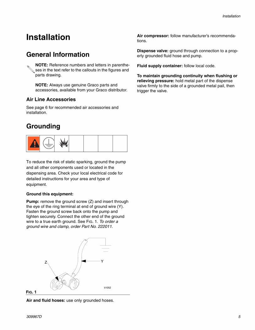
Pump: remove the ground screw (Z) and insert through the eye of the ring terminal at end of ground wire (Y). Fasten the ground screw back onto the pump and tighten securely. Connect the other end of the ground wire to a true earth ground. See FIG. 1. To order a ground wire and clamp, order Part No. 222011.
Air and fluid hoses: use only grounded hoses.
Air compressor: follow manufacturer’s recommenda-tions.
Dispense valve: ground through connection to a prop-erly grounded fluid hose and pump.
Fluid supply container: follow local code.
To maintain grounding continuity when flushing or relieving pressure: hold metal part of the dispense valve firmly to the side of a grounded metal pail, then trigger the valve.
NOTE: Reference numbers and letters in parenthe-ses in the text refer to the callouts in the figures and parts drawing.
NOTE: Always use genuine Graco parts and accessories, available from your Graco distributor.
FIG. 1
Z Y
ti1052
Installation
6 309967D
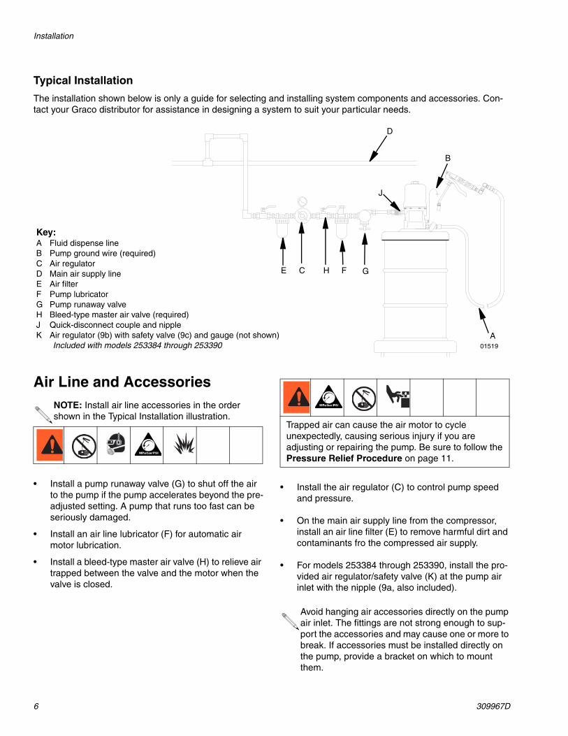
Typical Installation
The installation shown below is only a guide for selecting and installing system components and accessories. Con-tact your Graco distributor for assistance in designing a system to suit your particular needs.
Air Line and Accessories
• Install a pump runaway valve (G) to shut off the air to the pump if the pump accelerates beyond the pre-adjusted setting. A pump that runs too fast can be seriously damaged.
• Install an air line lubricator (F) for automatic air motor lubrication.
• Install a bleed-type master air valve (H) to relieve air trapped between the valve and the motor when the valve is closed.
• Install the air regulator (C) to control pump speed and pressure.
• On the main air supply line from the compressor, install an air line filter (E) to remove harmful dirt and contaminants fro the compressed air supply.
• For models 253384 through 253390, install the pro-vided air regulator/safety valve (K) at the pump air inlet with the nipple (9a, also included).
Key:A Fluid dispense lineB Pump ground wire (required)C Air regulatorD Main air supply lineE Air filterF Pump lubricatorG Pump runaway valveH Bleed-type master air valve (required)J Quick-disconnect couple and nippleK Air regulator (9b) with safety valve (9c) and gauge (not shown)
Included with models 253384 through 253390A
C
D
F GH
J
E
01519
B
NOTE: Install air line accessories in the order shown in the Typical Installation illustration.
Trapped air can cause the air motor to cycle unexpectedly, causing serious injury if you are adjusting or repairing the pump. Be sure to follow the Pressure Relief Procedure on page 11.
Avoid hanging air accessories directly on the pump air inlet. The fittings are not strong enough to sup-port the accessories and may cause one or more to break. If accessories must be installed directly on the pump, provide a bracket on which to mount them.
Installation
309967D 7
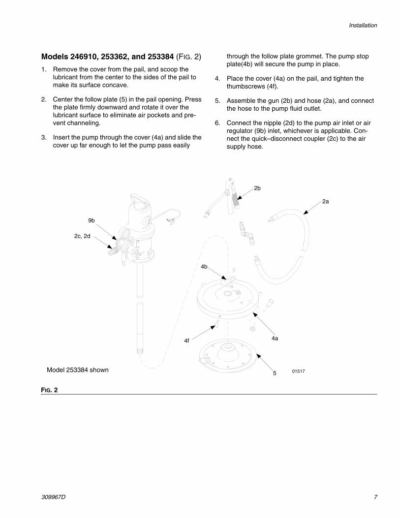
Models 246910, 253362, and 253384 (FIG. 2)
1. Remove the cover from the pail, and scoop the lubricant from the center to the sides of the pail to make its surface concave.
2. Center the follow plate (5) in the pail opening. Press the plate firmly downward and rotate it over the lubricant surface to eliminate air pockets and pre-vent channeling.
3. Insert the pump through the cover (4a) and slide the cover up far enough to let the pump pass easily
through the follow plate grommet. The pump stop plate(4b) will secure the pump in place.
4. Place the cover (4a) on the pail, and tighten the thumbscrews (4f).
5. Assemble the gun (2b) and hose (2a), and connect the hose to the pump fluid outlet.
6. Connect the nipple (2d) to the pump air inlet or air regulator (9b) inlet, whichever is applicable. Con-nect the quick–disconnect coupler (2c) to the air supply hose.
FIG. 2
9b
2c, 2d
4f
5
4a
2b
2a
Model 253384 shown 01517
4b
Installation
8 309967D
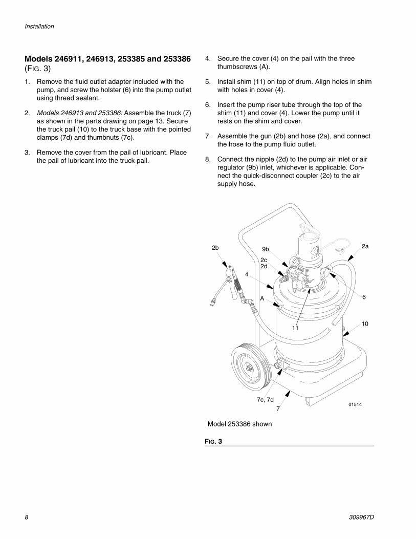
Models 246911, 246913, 253385 and 253386 (FIG. 3)
1. Remove the fluid outlet adapter included with the pump, and screw the holster (6) into the pump outlet using thread sealant.
2. Models 246913 and 253386: Assemble the truck (7) as shown in the parts drawing on page 13. Secure the truck pail (10) to the truck base with the pointed clamps (7d) and thumbnuts (7c).
3. Remove the cover from the pail of lubricant. Place the pail of lubricant into the truck pail.
4. Secure the cover (4) on the pail with the three thumbscrews (A).
5. Install shim (11) on top of drum. Align holes in shim with holes in cover (4).
6. Insert the pump riser tube through the top of the shim (11) and cover (4). Lower the pump until it rests on the shim and cover.
7. Assemble the gun (2b) and hose (2a), and connect the hose to the pump fluid outlet.
8. Connect the nipple (2d) to the pump air inlet or air regulator (9b) inlet, whichever is applicable. Con-nect the quick-disconnect coupler (2c) to the air supply hose.
FIG. 3
Model 253386 shown
01514
2a
4
A
7c, 7d
10
6
2c
9b2b
2d
7
11
Installation
309967D 9
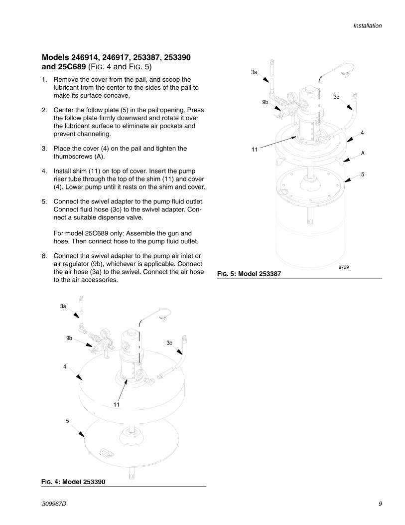
Models 246914, 246917, 253387, 253390 and 25C689 (FIG. 4 and FIG. 5)
1. Remove the cover from the pail, and scoop the lubricant from the center to the sides of the pail to make its surface concave.
2. Center the follow plate (5) in the pail opening. Press the follow plate firmly downward and rotate it over the lubricant surface to eliminate air pockets and prevent channeling.
3. Place the cover (4) on the pail and tighten the thumbscrews (A).
4. Install shim (11) on top of cover. Insert the pump riser tube through the top of the shim (11) and cover (4). Lower pump until it rests on the shim and cover.
5. Connect the swivel adapter to the pump fluid outlet. Connect fluid hose (3c) to the swivel adapter. Con-nect a suitable dispense valve.
For model 25C689 only: Assemble the gun and hose. Then connect hose to the pump fluid outlet.
6. Connect the swivel adapter to the pump air inlet or air regulator (9b), whichever is applicable. Connect the air hose (3a) to the swivel. Connect the air hose to the air accessories.
FIG. 4: Model 253390
3a
5
4
9b3c
11
FIG. 5: Model 2533878729
5
A
4
9b
3a
3c
11
Installation
10 309967D
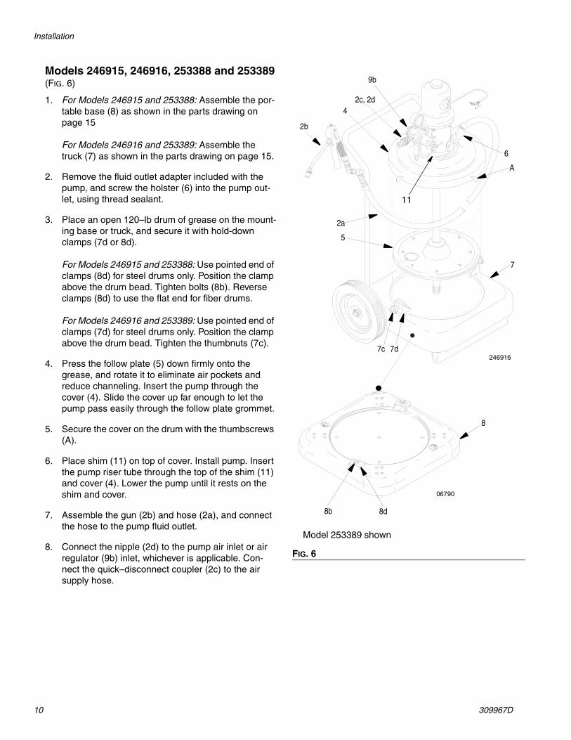
Models 246915, 246916, 253388 and 253389(FIG. 6)
1. For Models 246915 and 253388: Assemble the por-table base (8) as shown in the parts drawing on page 15
For Models 246916 and 253389: Assemble the truck (7) as shown in the parts drawing on page 15.
2. Remove the fluid outlet adapter included with the pump, and screw the holster (6) into the pump out-let, using thread sealant.
3. Place an open 120–lb drum of grease on the mount-ing base or truck, and secure it with hold-down clamps (7d or 8d).
For Models 246915 and 253388: Use pointed end of clamps (8d) for steel drums only. Position the clamp above the drum bead. Tighten bolts (8b). Reverse clamps (8d) to use the flat end for fiber drums.
For Models 246916 and 253389: Use pointed end of clamps (7d) for steel drums only. Position the clamp above the drum bead. Tighten the thumbnuts (7c).
4. Press the follow plate (5) down firmly onto the grease, and rotate it to eliminate air pockets and reduce channeling. Insert the pump through the cover (4). Slide the cover up far enough to let the pump pass easily through the follow plate grommet.
5. Secure the cover on the drum with the thumbscrews (A).
6. Place shim (11) on top of cover. Install pump. Insert the pump riser tube through the top of the shim (11) and cover (4). Lower the pump until it rests on the shim and cover.
7. Assemble the gun (2b) and hose (2a), and connect the hose to the pump fluid outlet.
8. Connect the nipple (2d) to the pump air inlet or air regulator (9b) inlet, whichever is applicable. Con-nect the quick–disconnect coupler (2c) to the air supply hose.
FIG. 6
Model 253389 shown
246916
4
5
8d
7d7c
A
2b
2a
6
7
06790
8b
2c, 2d
9b
8
11
Operation
309967D 11
Operation
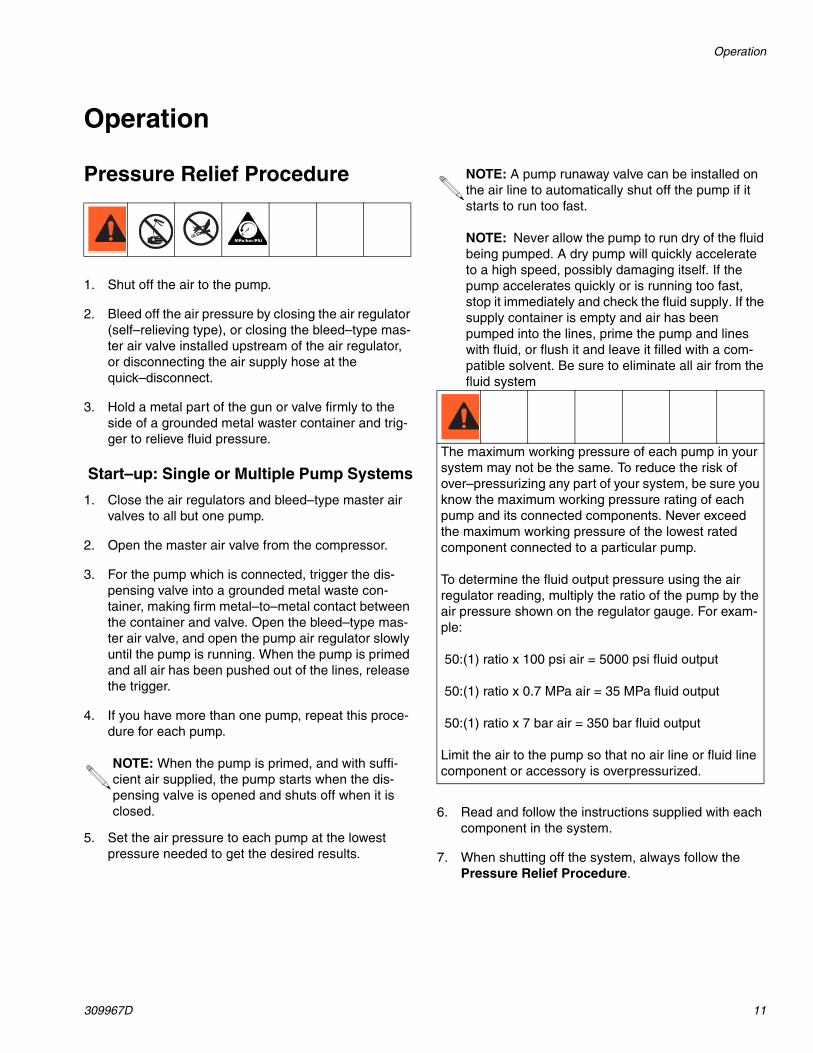
Pressure Relief Procedure
1. Shut off the air to the pump.
2. Bleed off the air pressure by closing the air regulator (self–relieving type), or closing the bleed–type mas-ter air valve installed upstream of the air regulator, or disconnecting the air supply hose at the quick–disconnect.
3. Hold a metal part of the gun or valve firmly to the side of a grounded metal waster container and trig-ger to relieve fluid pressure.
Start–up: Single or Multiple Pump Systems
1. Close the air regulators and bleed–type master air valves to all but one pump.
2. Open the master air valve from the compressor.
3. For the pump which is connected, trigger the dis-pensing valve into a grounded metal waste con-tainer, making firm metal–to–metal contact between the container and valve. Open the bleed–type mas-ter air valve, and open the pump air regulator slowly until the pump is running. When the pump is primed and all air has been pushed out of the lines, release the trigger.
4. If you have more than one pump, repeat this proce-dure for each pump.
5. Set the air pressure to each pump at the lowest pressure needed to get the desired results.
6. Read and follow the instructions supplied with each component in the system.
7. When shutting off the system, always follow the Pressure Relief Procedure.
NOTE: When the pump is primed, and with suffi-cient air supplied, the pump starts when the dis-pensing valve is opened and shuts off when it is closed.
NOTE: A pump runaway valve can be installed on the air line to automatically shut off the pump if it starts to run too fast.
NOTE: Never allow the pump to run dry of the fluid being pumped. A dry pump will quickly accelerate to a high speed, possibly damaging itself. If the pump accelerates quickly or is running too fast, stop it immediately and check the fluid supply. If the supply container is empty and air has been pumped into the lines, prime the pump and lines with fluid, or flush it and leave it filled with a com-patible solvent. Be sure to eliminate all air from the fluid system
The maximum working pressure of each pump in your system may not be the same. To reduce the risk of over–pressurizing any part of your system, be sure you know the maximum working pressure rating of each pump and its connected components. Never exceed the maximum working pressure of the lowest rated component connected to a particular pump.
To determine the fluid output pressure using the air regulator reading, multiply the ratio of the pump by the air pressure shown on the regulator gauge. For exam-ple:
50:(1) ratio x 100 psi air = 5000 psi fluid output
50:(1) ratio x 0.7 MPa air = 35 MPa fluid output
50:(1) ratio x 7 bar air = 350 bar fluid output
Limit the air to the pump so that no air line or fluid line component or accessory is overpressurized.
Parts
12 309967D
Parts
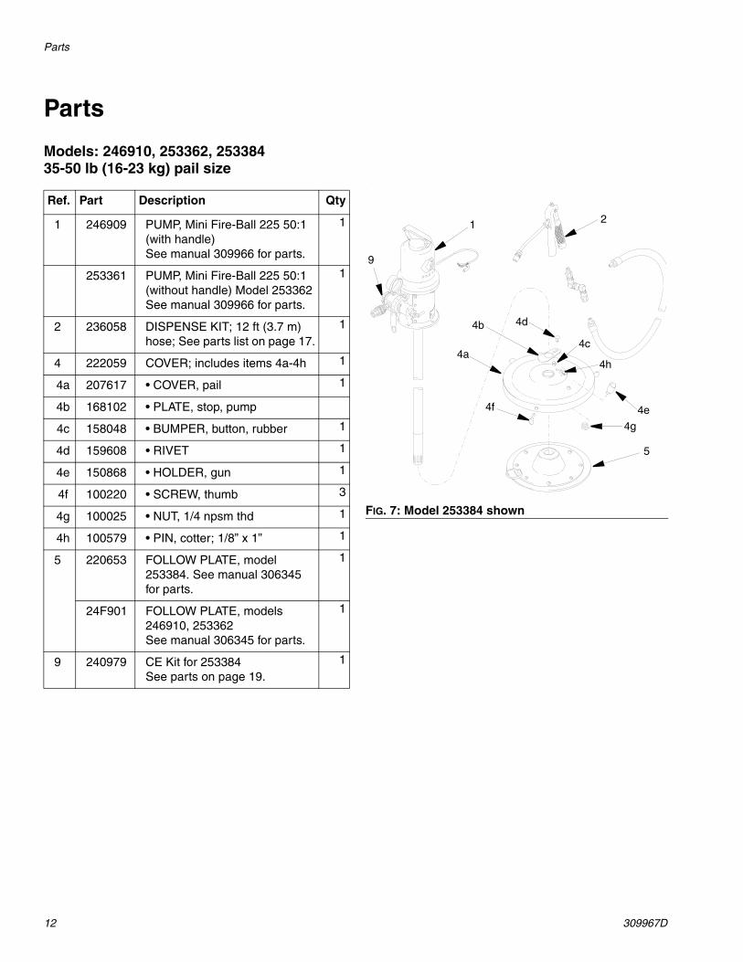
Models: 246910, 253362, 253384 35-50 lb (16-23 kg) pail size
.
Ref. Part Description Qty
1 246909 PUMP, Mini Fire-Ball 225 50:1(with handle) See manual 309966 for parts.
1
253361 PUMP, Mini Fire-Ball 225 50:1(without handle) Model 253362See manual 309966 for parts.
1
2 236058 DISPENSE KIT; 12 ft (3.7 m) hose; See parts list on page 17.
1
4 222059 COVER; includes items 4a-4h 1
4a 207617 • COVER, pail 1
4b 168102 • PLATE, stop, pump
4c 158048 • BUMPER, button, rubber 1
4d 159608 • RIVET 1
4e 150868 • HOLDER, gun 1
4f 100220 • SCREW, thumb 3
4g 100025 • NUT, 1/4 npsm thd 1
4h 100579 • PIN, cotter; 1/8” x 1” 1
5 220653 FOLLOW PLATE, model 253384. See manual 306345 for parts.
1
24F901 FOLLOW PLATE, models 246910, 253362See manual 306345 for parts.
1
9 240979 CE Kit for 253384See parts on page 19.
1
FIG. 7: Model 253384 shown
1
4d
2
9
4a
4b
4e
4h
4g
5
4f
4c
Parts
309967D 13
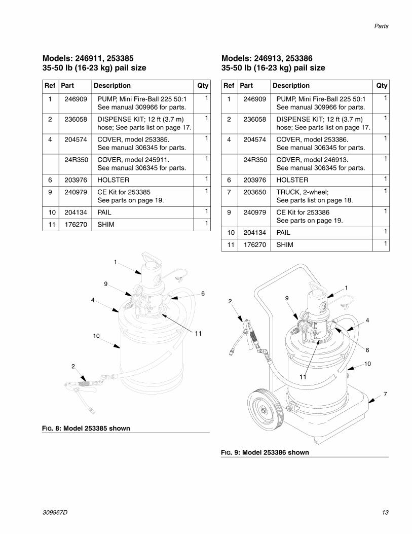
Models: 246911, 253385 35-50 lb (16-23 kg) pail size
Models: 246913, 253386 35-50 lb (16-23 kg) pail size
Ref Part Description Qty
1 246909 PUMP, Mini Fire-Ball 225 50:1See manual 309966 for parts.
1
2 236058 DISPENSE KIT; 12 ft (3.7 m) hose; See parts list on page 17.
1
4 204574 COVER, model 253385.See manual 306345 for parts.
1
24R350 COVER, model 245911.See manual 306345 for parts.
1
6 203976 HOLSTER 1
9 240979 CE Kit for 253385See parts on page 19.
1
10 204134 PAIL 1
11 176270 SHIM 1
FIG. 8: Model 253385 shown
1
6
2
10
4
9
11
Ref Part Description Qty
1 246909 PUMP, Mini Fire-Ball 225 50:1See manual 309966 for parts.
1
2 236058 DISPENSE KIT; 12 ft (3.7 m) hose; See parts list on page 17.
1
4 204574 COVER, model 253386.See manual 306345 for parts.
1
24R350 COVER, model 246913.See manual 306345 for parts.
1
6 203976 HOLSTER 1
7 203650 TRUCK, 2-wheel; See parts list on page 18.
1
9 240979 CE Kit for 253386See parts on page 19.
1
10 204134 PAIL 1
11 176270 SHIM 1
FIG. 9: Model 253386 shown
10
1
6
2
4
9
7
11
Parts
14 309967D
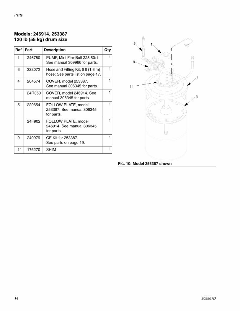
Models: 246914, 253387 120 lb (55 kg) drum size
Ref Part Description Qty
1 246780 PUMP, Mini Fire-Ball 225 50:1See manual 309966 for parts.
1
3 222072 Hose and Fitting Kit; 6 ft (1.8 m) hose; See parts list on page 17.
1
4 204574 COVER, model 253387.See manual 306345 for parts.
1
24R350 COVER, model 246914. See manual 306345 for parts.
1
5 220654 FOLLOW PLATE, model 253387. See manual 306345 for parts.
1
24F902 FOLLOW PLATE, model 246914. See manual 306345 for parts.
1
9 240979 CE Kit for 253387See parts on page 19.
1
11 176270 SHIM 1
FIG. 10: Model 253387 shown
3
9
1
4
5
11
Parts
309967D 15
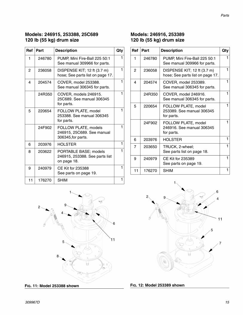
Models: 246915, 253388, 25C689120 lb (55 kg) drum size
Models: 246916, 253389 120 lb (55 kg) drum size
Ref Part Description Qty
1 246780 PUMP, Mini Fire-Ball 225 50:1See manual 309966 for parts.
1
2 236058 DISPENSE KIT; 12 ft (3.7 m) hose; See parts list on page 17.
1
4 204574 COVER, model 253388.See manual 306345 for parts.
1
24R350 COVER, models 246915. 25C689. See manual 306345 for parts.
1
5 220654 FOLLOW PLATE, model 253388. See manual 306345 for parts.
1
24F902 FOLLOW PLATE, models 246915, 25C689. See manual 306345,for parts.
1
6 203976 HOLSTER 1
8 203622 PORTABLE BASE; models 246915, 253388. See parts list on page 18.
1
9 240979 CE Kit for 235388See parts on page 19.
1
11 176270 SHIM 1
FIG. 11: Model 253388 shown
2
4
1
9
5
8
6
11
Ref Part Description Qty
1 246780 PUMP, Mini Fire-Ball 225 50:1See manual 309966 for parts.
1
2 236058 DISPENSE KIT; 12 ft (3.7 m) hose; See parts list on page 17.
1
4 204574 COVER, model 253389.See manual 306345 for parts.
1
24R350 COVER, model 246916.See manual 306345 for parts.
1
5 220654 FOLLOW PLATE, model 253389. See manual 306345 for parts.
1
24F902 FOLLOW PLATE, model 246916. See manual 306345 for parts.
1
6 203976 HOLSTER 1
7 203650 TRUCK, 2-wheel; See parts list on page 18.
1
9 240979 CE Kit for 235389See parts on page 19.
1
11 176270 SHIM 1
FIG. 12: Model 253389 shown
1
4
5
62
7
9
11
Parts
16 309967D
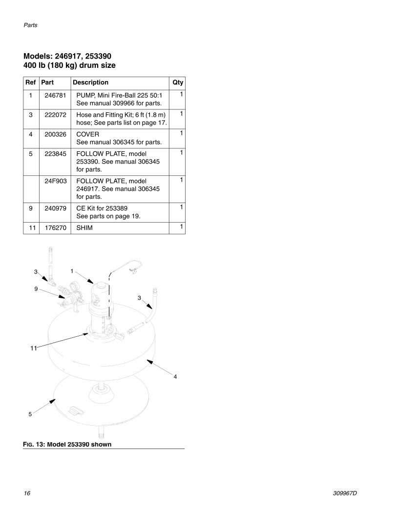
Models: 246917, 253390 400 lb (180 kg) drum size
Ref Part Description Qty
1 246781 PUMP, Mini Fire-Ball 225 50:1See manual 309966 for parts.
1
3 222072 Hose and Fitting Kit; 6 ft (1.8 m) hose; See parts list on page 17.
1
4 200326 COVERSee manual 306345 for parts.
1
5 223845 FOLLOW PLATE, model 253390. See manual 306345 for parts.
1
24F903 FOLLOW PLATE, model 246917. See manual 306345 for parts.
1
9 240979 CE Kit for 253389See parts on page 19.
1
11 176270 SHIM 1
FIG. 13: Model 253390 shown
5
1
4
9
3
3
11
Parts
309967D 17
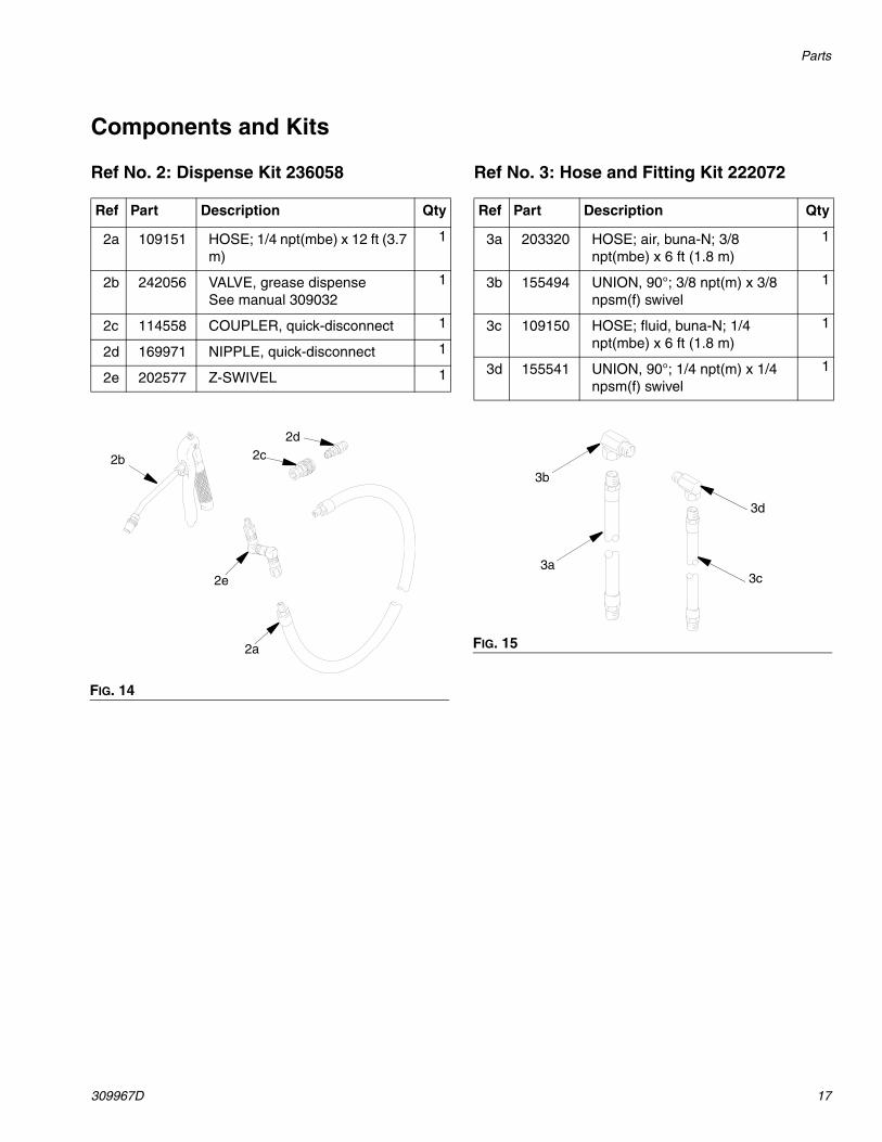
Components and Kits
Ref No. 2: Dispense Kit 236058 Ref No. 3: Hose and Fitting Kit 222072
Ref Part Description Qty
2a 109151 HOSE; 1/4 npt(mbe) x 12 ft (3.7 m)
1
2b 242056 VALVE, grease dispenseSee manual 309032
1
2c 114558 COUPLER, quick-disconnect 1
2d 169971 NIPPLE, quick-disconnect 1
2e 202577 Z-SWIVEL 1
FIG. 14
2c
2a
2d
2b
2e
Ref Part Description Qty
3a 203320 HOSE; air, buna-N; 3/8 npt(mbe) x 6 ft (1.8 m)
1
3b 155494 UNION, 90°; 3/8 npt(m) x 3/8 npsm(f) swivel
1
3c 109150 HOSE; fluid, buna-N; 1/4 npt(mbe) x 6 ft (1.8 m)
1
3d 155541 UNION, 90°; 1/4 npt(m) x 1/4 npsm(f) swivel
1
FIG. 15
3d
3c
3b
3a
Parts
18 309967D
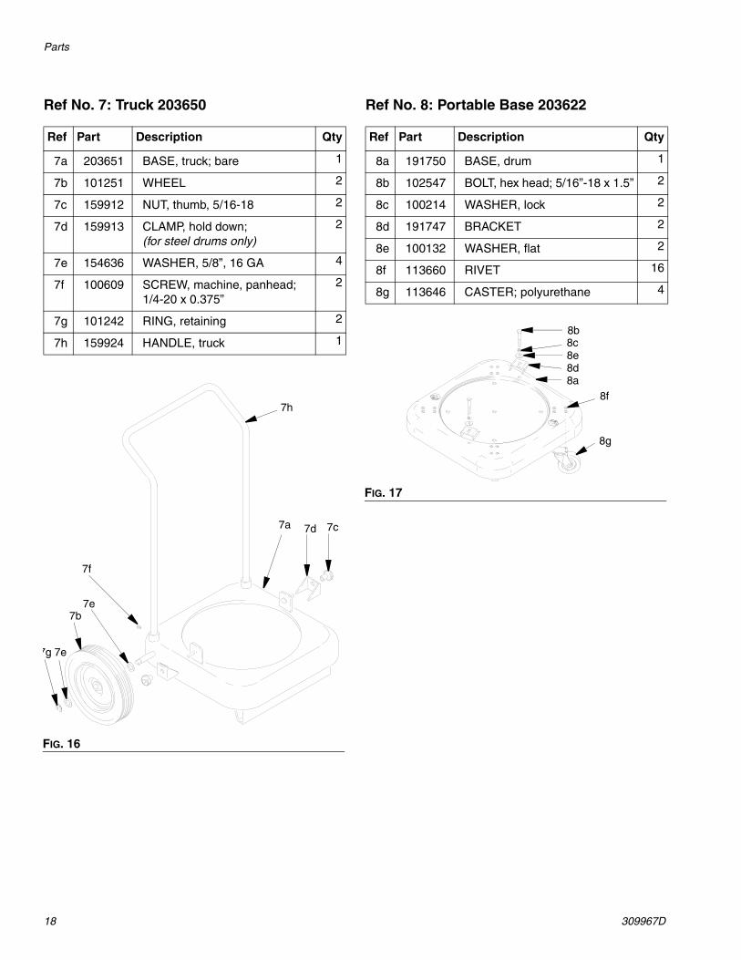
Ref No. 7: Truck 203650 Ref No. 8: Portable Base 203622
Ref Part Description Qty
7a 203651 BASE, truck; bare 1
7b 101251 WHEEL 2
7c 159912 NUT, thumb, 5/16-18 2
7d 159913 CLAMP, hold down; (for steel drums only)
2
7e 154636 WASHER, 5/8”, 16 GA 4
7f 100609 SCREW, machine, panhead; 1/4-20 x 0.375”
2
7g 101242 RING, retaining 2
7h 159924 HANDLE, truck 1
FIG. 16
7h
7d 7c
7f
7e7b
7g 7e
7a
Ref Part Description Qty
8a 191750 BASE, drum 1
8b 102547 BOLT, hex head; 5/16”-18 x 1.5” 2
8c 100214 WASHER, lock 2
8d 191747 BRACKET 2
8e 100132 WASHER, flat 2
8f 113660 RIVET 16
8g 113646 CASTER; polyurethane 4
FIG. 17
8b8c8e8d8a
8f
8g
Sound Data
309967D 19
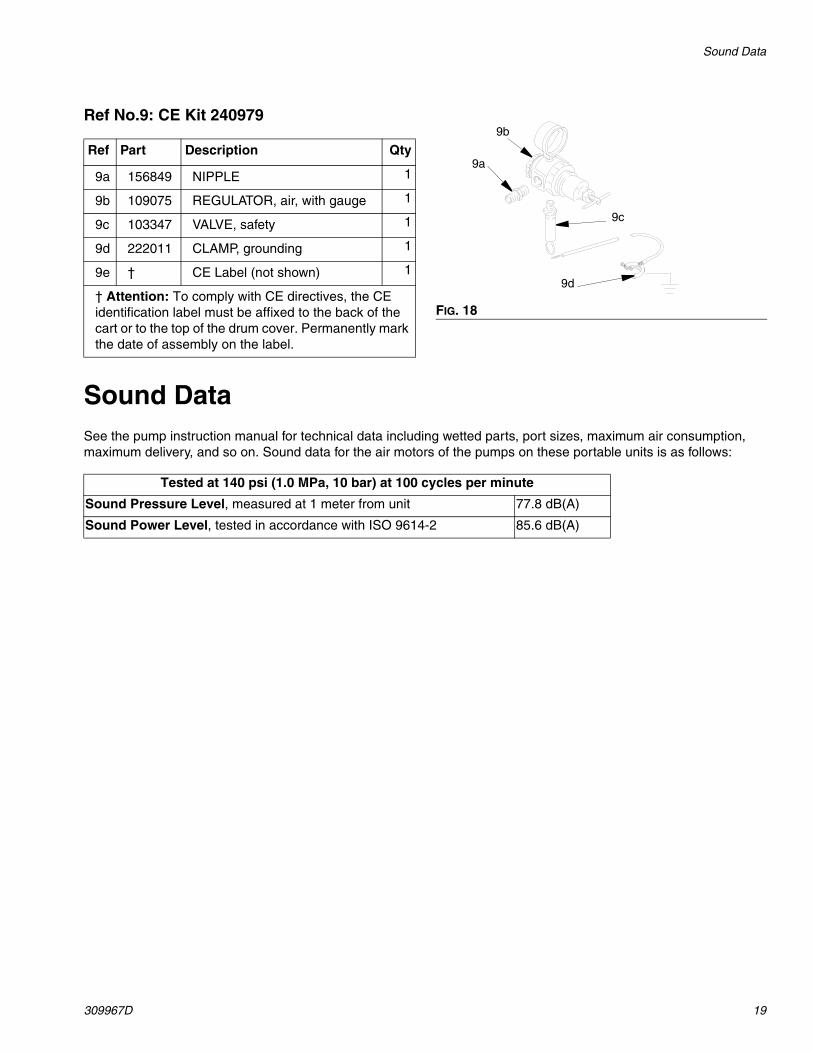
Ref No.9: CE Kit 240979
Sound DataSee the pump instruction manual for technical data including wetted parts, port sizes, maximum air consumption, maximum delivery, and so on. Sound data for the air motors of the pumps on these portable units is as follows:
Ref Part Description Qty
9a 156849 NIPPLE 1
9b 109075 REGULATOR, air, with gauge 1
9c 103347 VALVE, safety 1
9d 222011 CLAMP, grounding 1
9e † CE Label (not shown) 1
† Attention: To comply with CE directives, the CE identification label must be affixed to the back of the cart or to the top of the drum cover. Permanently mark the date of assembly on the label.
FIG. 18
9c
9d
9a
9b
Tested at 140 psi (1.0 MPa, 10 bar) at 100 cycles per minute
Sound Pressure Level, measured at 1 meter from unit 77.8 dB(A)
Sound Power Level, tested in accordance with ISO 9614-2 85.6 dB(A)

All written and visual data contained in this document reflects the latest product information available at the time of publication. Graco reserves the right to make changes at any time without notice.
Original instructions. This manual contains English. MM 309678
Graco Headquarters: MinneapolisInternational Offices: Belgium, China, Japan, Korea
GRACO INC. AND SUBSIDIARIES • P.O. BOX 1441 • MINNEAPOLIS MN 55440-1441 • USA
Copyright 2007, Graco Inc. All Graco manufacturing locations are registered to ISO 9001.www.graco.com
revised January 2017
Graco Information For the latest information about Graco products, visit www.graco.com.
For patent information, see www.graco.com/patents.
TO PLACE AN ORDER, contact your Graco distributor or call to identify the nearest distributor.Phone: 612-623-6928 or Toll Free: 1-800-533-9655, Fax: 612-378-3590