Embed Size (px)
Citation preview
Graco Inc. P.O. Box 1441 Minneapolis, MN 55440-1441Copyright 2003, Graco Inc. is registered to I.S. EN ISO 9001
249020, Series B, Transceiver with Full Line Matrix™ Software, North America249884, Series B, Transceiver with Full Line Matrix™ Software, Australia249021, Series B, Transceiver with Tank Level Monitor Software, North America249885, Series B, Transceiver with Tank Level Monitor Software, Australia117256, Series C, Transceiver without Software, North America120108, Series C, Transceiver without Software, Australia
For use with Matrix Total FluidManagement System Components
The Matrix Transceiver contains an RF device with the following approvals:
Important Safety InstructionsRead all warnings and instructions in this manual. Save these instructions.
FCC ID: JHIGNETIC: 4840AGNET
Industry Canada StatementThe term “IC” before the certification/reg-istration number only signifies that the In-dustry Canada technical specificationswere met.
Part No. 117256 Shown117256 shown
309498H
Instruction Manual
Transceiver
✓Australian Vendor Code: N3845
EN
Manual Conventions
2 309498H
ContentsManual Conventions . . . . . . . . . . . . . . . . . . . . . . . . 2Warnings . . . . . . . . . . . . . . . . . . . . . . . . . . . . . . . . . 3Typical Transceiver Installations . . . . . . . . . . . . . . 4Transceiver Connections . . . . . . . . . . . . . . . . . . . . 5Changing Dipswitch Settings . . . . . . . . . . . . . . . . . 9Operation . . . . . . . . . . . . . . . . . . . . . . . . . . . . . . . . 13Transceiver Parts . . . . . . . . . . . . . . . . . . . . . . . . . . 14
Troubleshooting . . . . . . . . . . . . . . . . . . . . . . . . . . . 15Technical Data . . . . . . . . . . . . . . . . . . . . . . . . . . . . 16Dimensions . . . . . . . . . . . . . . . . . . . . . . . . . . . . . . . 17Mounting Bracket Hole Dimensions . . . . . . . . . . 17Graco Standard Warranty . . . . . . . . . . . . . . . . . . . 18Graco Information . . . . . . . . . . . . . . . . . . . . . . . . . 18
Manual Conventions
Warning Caution
Note
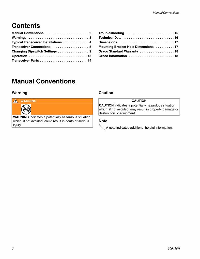
WARNING
WARNING indicates a potentially hazardous situation which, if not avoided, could result in death or serious injury.
CAUTIONCAUTION indicates a potentially hazardous situation which, if not avoided, may result in property damage or destruction of equipment.
A note indicates additional helpful information.
Warnings
309498H 3
WarningsThe following general warnings are related to the safe setup, use, grounding, maintenance and repair of this equip-ment. Additional more specific warnings may be found throughout the text of this manual where applicable.
WARNINGFIRE AND EXPLOSION HAZARDWhen flammable fluids are present in the work area, such as gasoline and windshield wiper fluid, be aware that flammable fumes can ignite or explode. To help prevent fire and explosion:
• Use equipment only in well ventilated area.
• Eliminate all ignition sources, such as cigarettes and portable electric lamps.
• Keep work area free of debris, including rags and spilled or open containers of solvent and gasoline.
• Do not plug or unplug power cords or turn lights on or off when flammable fumes are present.
• Ground equipment.
• Use only grounded hoses.
• If there is static sparking or you feel a shock, stop operation immediately. Do not use equipment until you identify and correct the problem.
EQUIPMENT MISUSE HAZARDMisuse can cause death or serious injury.
• Do not exceed the maximum working pressure or temperature rating of the lowest rated system component. See Technical Data in all equipment manuals.
• Use fluids and solvents that are compatible with equipment wetted parts. See Technical Data in all equipment manuals. Read fluid and solvent manufacturer’s warnings.
• Check equipment daily. Repair or replace worn or damaged parts immediately.
• Do not alter or modify equipment.
• For professional use only.
• Use equipment only for its intended purpose. Call your Graco distributor for information.
• Route hoses and cables away from traffic areas, sharp edges, moving parts, and hot surfaces.
• Do not use hoses to pull equipment.
• Comply with all applicable safety regulations.
Typical Transceiver Installations
4 309498H
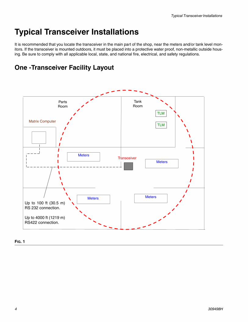
Typical Transceiver InstallationsIt is recommended that you locate the transceiver in the main part of the shop, near the meters and/or tank level mon-itors. If the transceiver is mounted outdoors, it must be placed into a protective water proof, non-metallic outside hous-ing. Be sure to comply with all applicable local, state, and national fire, electrical, and safety regulations.
One -Transceiver Facility Layout
FIG. 1
Meters
Meters
Meters Meters
Transceiver
Tank Room
PartsRoom
Matrix ComputerTLM
TLM
Up to 100 ft (30.5 m)RS 232 connection.
Up to 4000 ft (1219 m)RS422 connection.

Transceiver Connections
309498H 5
Two -Transceiver Facility Layout
Transceiver Connections
• Transceivers use a power transformer plugged into the power connector (A). See FIG. 3.
• The serial port connector (B) is used for the Trans-ceiver to PC cable connection when RS232 cable is used to connect the transceiver to the Matrix PC. See Transceiver Connection/Wiring on page 6.
• The serial port connector (C) is used for the Trans-ceiver to PC cable connection when RS422 cable and convertor is used to connect the transceiver to the Matrix PC. See Transceiver Connection/Wir-ing on page 6.
FIG. 2
Meters
Meters
MetersMeters
Transceiver 1
Tank Room
PartsRoom
Matrix ComputerTLM
TLM
Transceiver 2
WARNING
Read Warnings on page 3.
FIG. 3A
BC
Transceiver Connections
6 309498H
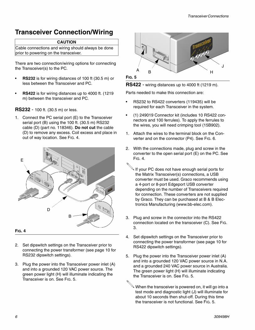
Transceiver Connection/Wiring
There are two connection/wiring options for connecting the Transceiver(s) to the PC.
• RS232 is for wiring distances of 100 ft (30.5 m) or less between the Transceiver and PC.
• RS422 is for wiring distances up to 4000 ft. (1219 m) between the transceiver and PC.
RS232 - 100 ft. (30.5 m) or less.
1. Connect the PC serial port (E) to the Transceiver serial port (B) using the 100 ft. (30.5 m) RS232 cable (D) (part no. 118346). Do not cut the cable (D) to remove any excess. Coil excess and place in out of way location. See FIG. 4.
2. Set dipswitch settings on the Transceiver prior to connecting the power transformer (see page 10 for RS232 dipswitch settings).
3. Plug the power into the Transceiver power inlet (A) and into a grounded 120 VAC power source. The green power light (H) will illuminate indicating the Transceiver is on. See FIG. 5.
RS422 - wiring distances up to 4000 ft (1219 m).
Parts needed to make this connection are:
• RS232 to RS422 converters (119435) will be required for each Transceiver in the system.
• (1) 249019 Connector kit (includes 10 RS422 con-nectors and 100 ferrules). To apply the ferrules to the wires, you will need crimping tool (15B902).
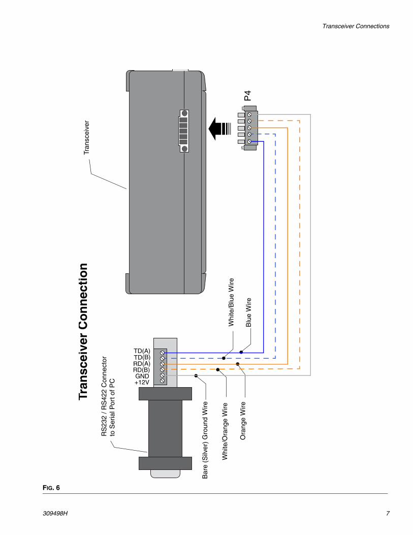
1. Attach the wires to the terminal block on the Con-verter and on the connector (P4). See FIG. 6.
2. With the connections made, plug and screw in the converter to the open serial port (E) on the PC. See FIG. 4.
3. Plug and screw in the connector into the RS422 connection located on the transceiver (C). See FIG. 3.
4. Set dipswitch settings on the Transceiver prior to connecting the power transformer (see page 10 for RS422 dipswitch settings).
5. Plug the power into the Transceiver power inlet (A) and into a grounded 120 VAC power source in N.A. and a grounded 240 VAC power source in Australia. The green power light (H) will illuminate indicating the Transceiver is on. See FIG. 5.
CAUTIONCable connections and wiring should always be done prior to powering on the transceiver.
FIG. 4
D
E
B
FIG. 5
If your PC does not have enough serial ports for the Matrix Transceiver(s) connections, a USBconverter must be used. Graco recommends using a 4-port or 8-port Edgeport USB converter depending on the number of Transceivers required for connection. These converters are not supplied by Graco. They can be purchased at B & B Elec-tronics Manufacturing (www.bb-elec.com).
When the transceiver is powered on, it will go into a test mode and diagnostic light (J) will illuminate for about 10 seconds then shut-off. During this time the transceiver is not functional. See FIG. 5.
A B H
J
Transceiver Connections
309498H 7
FIG. 6
Tran
scei
ver
Co
nn
ecti
on
Tra
nsce
iver
RS
232
/ RS
422
Con
nect
or
to S
eria
l Por
t of P
C
Whi
te/O
rang
e W
ire
Blu
e W
ireO
rang
e W
ire
Whi
te/B
lue
Wire
Bar
e (S
ilver
) G
roun
d W
ire
P4
+12VGND
RD(B)RD(A)TD(B)TD(A)
Transceiver Connections
8 309498H
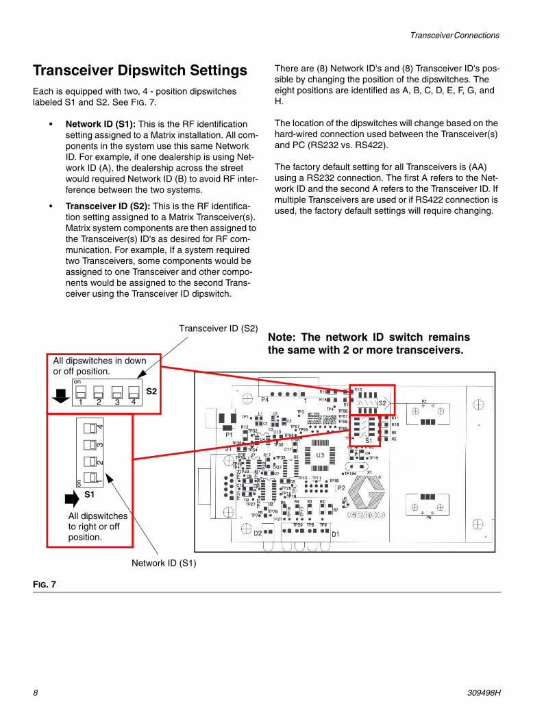
Transceiver Dipswitch SettingsEach is equipped with two, 4 - position dipswitches labeled S1 and S2. See FIG. 7.
• Network ID (S1): This is the RF identification setting assigned to a Matrix installation. All com-ponents in the system use this same Network ID. For example, if one dealership is using Net-work ID (A), the dealership across the street would required Network ID (B) to avoid RF inter-ference between the two systems.
• Transceiver ID (S2): This is the RF identifica-tion setting assigned to a Matrix Transceiver(s). Matrix system components are then assigned to the Transceiver(s) ID's as desired for RF com-munication. For example, If a system required two Transceivers, some components would be assigned to one Transceiver and other compo-nents would be assigned to the second Trans-ceiver using the Transceiver ID dipswitch.
There are (8) Network ID's and (8) Transceiver ID's pos-sible by changing the position of the dipswitches. The eight positions are identified as A, B, C, D, E, F, G, and H.
The location of the dipswitches will change based on the hard-wired connection used between the Transceiver(s) and PC (RS232 vs. RS422).
The factory default setting for all Transceivers is (AA) using a RS232 connection. The first A refers to the Net-work ID and the second A refers to the Transceiver ID. If multiple Transceivers are used or if RS422 connection is used, the factory default settings will require changing.
FIG. 7
Network ID (S1)
Transceiver ID (S2)
1 2 3 4S2
on
12
34
S1
on
All dipswitches in down or off position.
All dipswitchesto right or offposition.
Note: The network ID switch remainsthe same with 2 or more transceivers.
Changing Dipswitch Settings
309498H 9
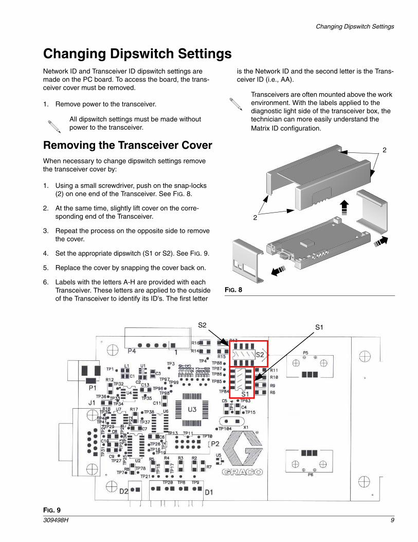
Changing Dipswitch SettingsNetwork ID and Transceiver ID dipswitch settings are made on the PC board. To access the board, the trans-ceiver cover must be removed.
1. Remove power to the transceiver.
All dipswitch settings must be made without power to the transceiver.
Removing the Transceiver CoverWhen necessary to change dipswitch settings remove the transceiver cover by:
1. Using a small screwdriver, push on the snap-locks (2) on one end of the Transceiver. See FIG. 8.
2. At the same time, slightly lift cover on the corre-sponding end of the Transceiver.
3. Repeat the process on the opposite side to remove the cover.
4. Set the appropriate dipswitch (S1 or S2). See FIG. 9.
5. Replace the cover by snapping the cover back on.
6. Labels with the letters A-H are provided with each Transceiver. These letters are applied to the outside of the Transceiver to identify its ID's. The first letter
is the Network ID and the second letter is the Trans-ceiver ID (i.e., AA).
Transceivers are often mounted above the work environment. With the labels applied to the diagnostic light side of the transceiver box, the technician can more easily understand the Matrix ID configuration.
FIG. 8
2
2
FIG. 9
S2 S1
Changing Dipswitch Settings
10 309498H
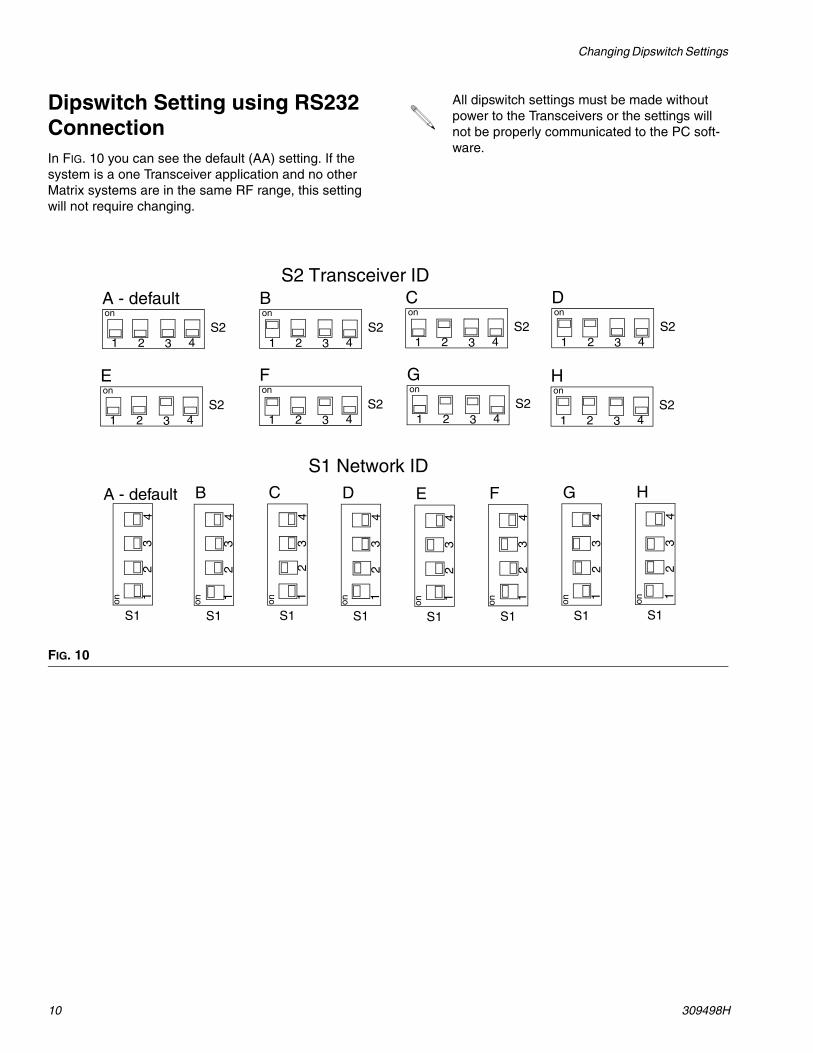
Dipswitch Setting using RS232 ConnectionIn FIG. 10 you can see the default (AA) setting. If the system is a one Transceiver application and no other Matrix systems are in the same RF range, this setting will not require changing.
All dipswitch settings must be made without power to the Transceivers or the settings will not be properly communicated to the PC soft-ware.
FIG. 10
A - defaultS2 Transceiver ID
1 2 3 4S2
onB
1 2 3 4S2
onC
1 2 3 4S2
onD
1 2 3 4S2
on
G
1 2 3 4S2
onH
1 2 3 4S2
onF
1 2 3 4S2
onE
1 2 3 4S2
on
H
S1 Network ID
12
34
S1
on
A - default
12
34
S1
on
C
12
34
S1
on
B
12
34
S1
on
D
12
34
S1
on
E
12
34
S1
on
F
12
34
S1
onG
12
34
S1
on
Changing Dipswitch Settings
309498H 11
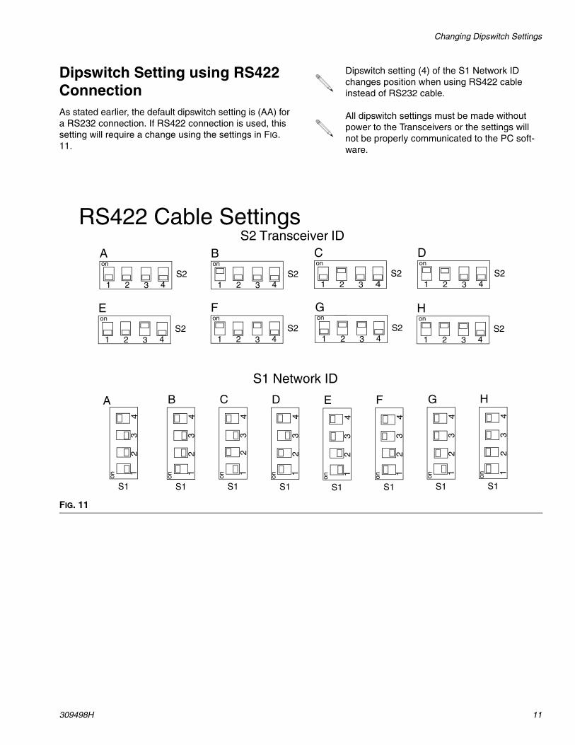
Dipswitch Setting using RS422 ConnectionAs stated earlier, the default dipswitch setting is (AA) for a RS232 connection. If RS422 connection is used, this setting will require a change using the settings in FIG. 11.
Dipswitch setting (4) of the S1 Network ID changes position when using RS422 cable instead of RS232 cable.
All dipswitch settings must be made without power to the Transceivers or the settings will not be properly communicated to the PC soft-ware.
FIG. 11
S1 Network ID
H
12
34
S1on
A
12
34
S1
on
C
12
34
S1
on
B
12
34
S1
on
D
12
34
S1
on
E
12
34
S1
on
F1
23
4
S1
on
G
12
34
S1
on
A S2 Transceiver ID
1 2 3 4S2
onB
1 2 3 4S2
onC
1 2 3 4S2
onD
1 2 3 4S2
on
G
1 2 3 4S2
onH
1 2 3 4S2
onF
1 2 3 4S2
onE
1 2 3 4S2
on
RS422 Cable Settings

Changing Dipswitch Settings
12 309498H
Components Mounting BracketDuring system installation, double-faced tape can be used to allow relocation of the Transceivers to optimize RF communication.
Once RF communications are confirmed, the Trans-ceiver can be permanently mounted on a desk top, wall, or ceiling. If the component will be placed on a desktop or horizontal flat surface, use the rubber feet that are supplied. The feet are adhered to round indents on the back side of the unit. If the component will be placed on the wall or ceiling, use the Matrix mounting bracket (3) and screws (4) to fasten the box to the mounting loca-tion. See FIG. 12.
1. Using the bracket as a template, mark the location of the bracket holes on the mounting surface. Or see Mounting Bracket Hole Dimensions, page 17.
2. Drill two holes.
3. Attach the bracket (3) to the wall or ceiling using two 1 in. sheet rock screws (4). Slide the transceiver onto the bracket.
• If the Transceiver is mounted outdoors, it must be placed into a protective water proof, non-metallic outside housing meeting IP65 Standards for outdoor use.
• Be sure to comply with all applicable local, state, and national fire, electrical, and safety regulations.
FIG. 12
3
4
Operation
309498H 13
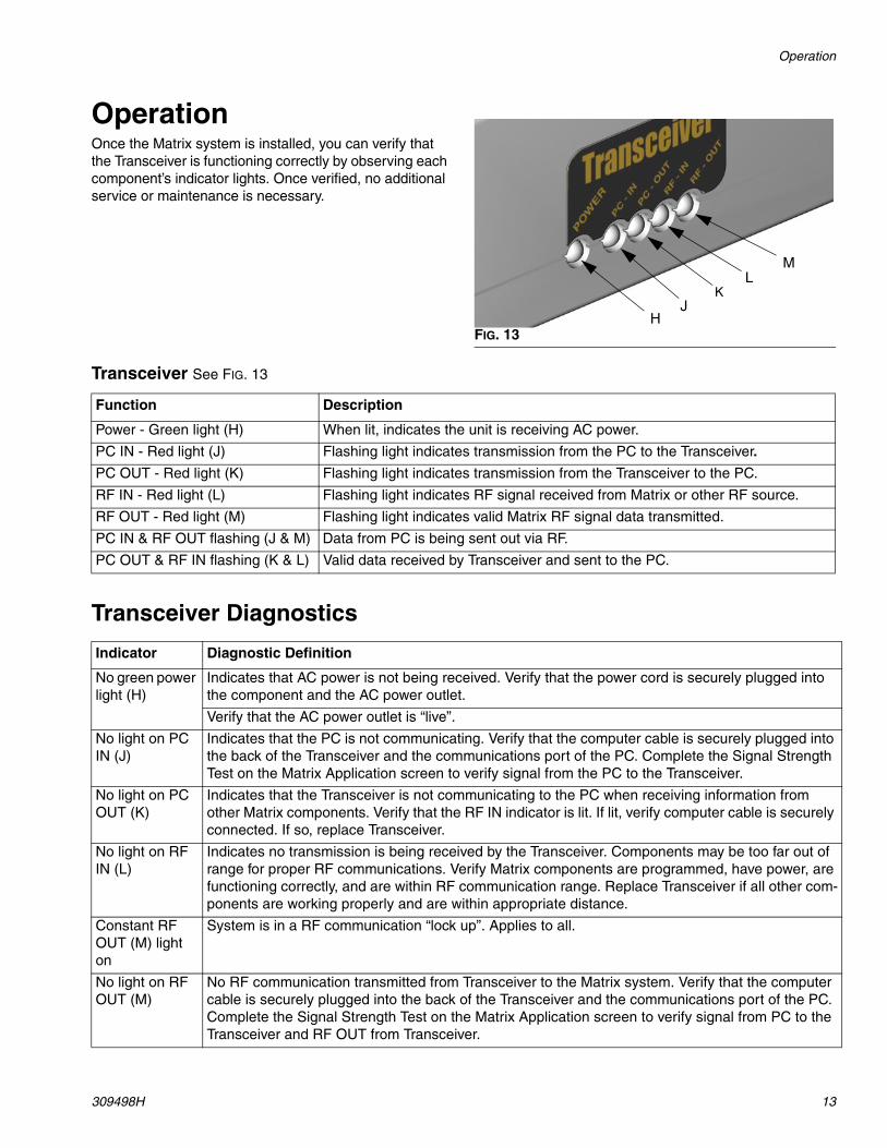
OperationOnce the Matrix system is installed, you can verify that the Transceiver is functioning correctly by observing each component’s indicator lights. Once verified, no additional service or maintenance is necessary.
Transceiver See FIG. 13
Transceiver Diagnostics
FIG. 13
JK
LM
H
Function Description
Power - Green light (H) When lit, indicates the unit is receiving AC power.
PC IN - Red light (J) Flashing light indicates transmission from the PC to the Transceiver.
PC OUT - Red light (K) Flashing light indicates transmission from the Transceiver to the PC.
RF IN - Red light (L) Flashing light indicates RF signal received from Matrix or other RF source.
RF OUT - Red light (M) Flashing light indicates valid Matrix RF signal data transmitted.
PC IN & RF OUT flashing (J & M) Data from PC is being sent out via RF.
PC OUT & RF IN flashing (K & L) Valid data received by Transceiver and sent to the PC.
Indicator Diagnostic Definition
No green power light (H)
Indicates that AC power is not being received. Verify that the power cord is securely plugged into the component and the AC power outlet.
Verify that the AC power outlet is “live”.
No light on PC IN (J)
Indicates that the PC is not communicating. Verify that the computer cable is securely plugged into the back of the Transceiver and the communications port of the PC. Complete the Signal Strength Test on the Matrix Application screen to verify signal from the PC to the Transceiver.
No light on PC OUT (K)
Indicates that the Transceiver is not communicating to the PC when receiving information from other Matrix components. Verify that the RF IN indicator is lit. If lit, verify computer cable is securely connected. If so, replace Transceiver.
No light on RF IN (L)
Indicates no transmission is being received by the Transceiver. Components may be too far out of range for proper RF communications. Verify Matrix components are programmed, have power, are functioning correctly, and are within RF communication range. Replace Transceiver if all other com-ponents are working properly and are within appropriate distance.
Constant RF OUT (M) light on
System is in a RF communication “lock up”. Applies to all.
No light on RF OUT (M)
No RF communication transmitted from Transceiver to the Matrix system. Verify that the computer cable is securely plugged into the back of the Transceiver and the communications port of the PC. Complete the Signal Strength Test on the Matrix Application screen to verify signal from PC to the Transceiver and RF OUT from Transceiver.
Transceiver Parts
14 309498H
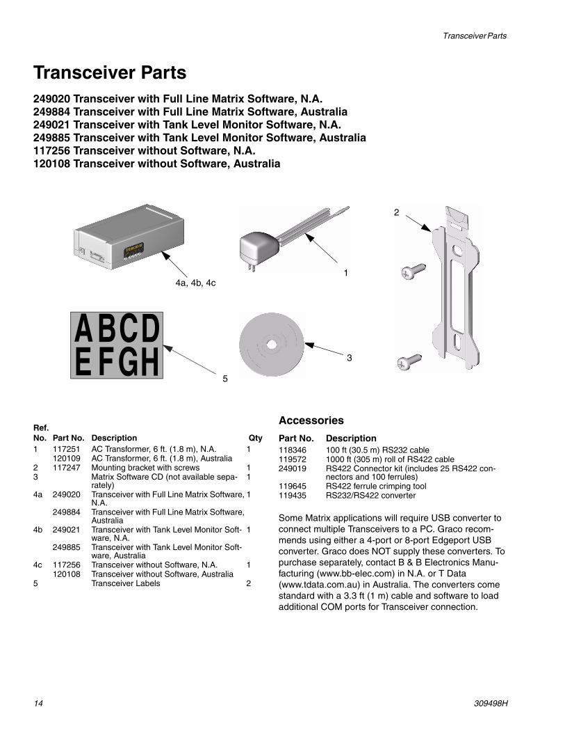
Transceiver Parts249020 Transceiver with Full Line Matrix Software, N.A.249884 Transceiver with Full Line Matrix Software, Australia249021 Transceiver with Tank Level Monitor Software, N.A.249885 Transceiver with Tank Level Monitor Software, Australia117256 Transceiver without Software, N.A.120108 Transceiver without Software, Australia
Accessories
Some Matrix applications will require USB converter to connect multiple Transceivers to a PC. Graco recom-mends using either a 4-port or 8-port Edgeport USB converter. Graco does NOT supply these converters. To purchase separately, contact B & B Electronics Manu-facturing (www.bb-elec.com) in N.A. or T Data (www.tdata.com.au) in Australia. The converters come standard with a 3.3 ft (1 m) cable and software to load additional COM ports for Transceiver connection.
3
2
14a, 4b, 4c
5
A BCDE FGH
Ref. No. Part No. Description Qty1 117251 AC Transformer, 6 ft. (1.8 m), N.A. 1
120109 AC Transformer, 6 ft. (1.8 m), Australia2 117247 Mounting bracket with screws 13 Matrix Software CD (not available sepa-
rately)1
4a 249020 Transceiver with Full Line Matrix Software, N.A.
1
249884 Transceiver with Full Line Matrix Software, Australia
4b 249021 Transceiver with Tank Level Monitor Soft-ware, N.A.
1
249885 Transceiver with Tank Level Monitor Soft-ware, Australia
4c 117256 Transceiver without Software, N.A. 1120108 Transceiver without Software, Australia
5 Transceiver Labels 2
Part No. Description118346 100 ft (30.5 m) RS232 cable119572 1000 ft (305 m) roll of RS422 cable249019 RS422 Connector kit (includes 25 RS422 con-
nectors and 100 ferrules)119645 RS422 ferrule crimping tool119435 RS232/RS422 converter

Troubleshooting
309498H 15
Troubleshooting
Problem Cause Solution
Transceiver will not com-municate to meters and TLMs
Incorrect COM port selected for trans-ceiver.
Ensure correct COM port is selected.
Communication (serial) cable is not connected between the transceiver and PC.
Verify that communication cable con-nects transceiver to PC correctly. See page 6.
Transceiver is not powered up. Verify transceiver is powered up.
You attempted to communicate while red lights on transceiver were on.
Wait for red lights on transceiver to go blank before attempting to communi-cate.
Transceiver dipswitches are not set for correct communication (serial) cable.
Verify transceiver dipswitches are set for appropriate communication (serial) cable. See pages 10 and 11.
Transceiver is out of RF range of meters or TLMs.
Ensure transceiver is located within RF range of meters and TLMs.
Transceiver communi-cates intermittently to some meters and TLMs.
Transceiver is out of RF range of meters or TLMs.
Ensure transceiver is located within RF range of meters and TLMs.
Two meters or TLMs are programmed to the same address.
Verify that each meter and TLM is cor-rectly programmed to a unique address.
Technical Data
16 309498H
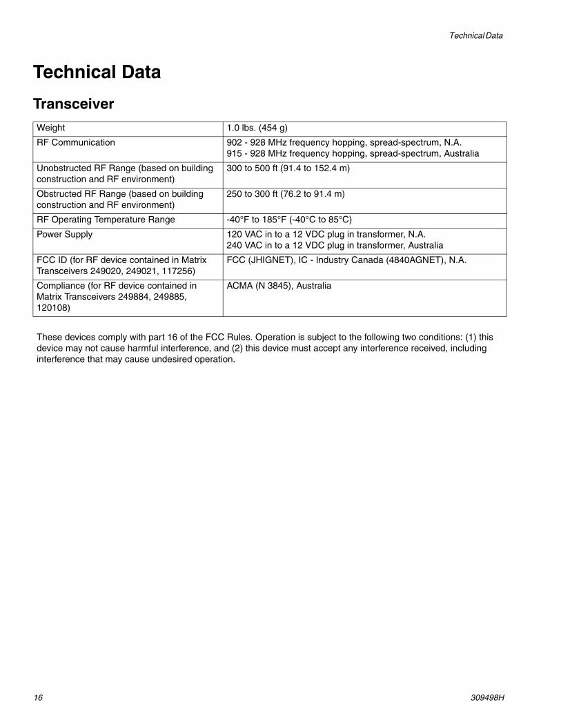
Technical Data
Transceiver
Weight 1.0 lbs. (454 g)
RF Communication 902 - 928 MHz frequency hopping, spread-spectrum, N.A.915 - 928 MHz frequency hopping, spread-spectrum, Australia
Unobstructed RF Range (based on building construction and RF environment)
300 to 500 ft (91.4 to 152.4 m)
Obstructed RF Range (based on building construction and RF environment)
250 to 300 ft (76.2 to 91.4 m)
RF Operating Temperature Range -40°F to 185°F (-40°C to 85°C)
Power Supply 120 VAC in to a 12 VDC plug in transformer, N.A.240 VAC in to a 12 VDC plug in transformer, Australia
FCC ID (for RF device contained in Matrix Transceivers 249020, 249021, 117256)
FCC (JHIGNET), IC - Industry Canada (4840AGNET), N.A.
Compliance (for RF device contained in Matrix Transceivers 249884, 249885, 120108)
ACMA (N 3845), Australia
These devices comply with part 16 of the FCC Rules. Operation is subject to the following two conditions: (1) this device may not cause harmful interference, and (2) this device must accept any interference received, including interference that may cause undesired operation.
Dimensions
309498H 17
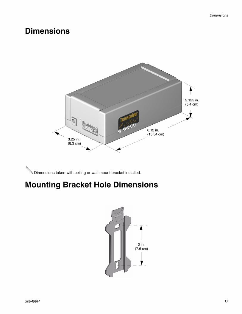
Dimensions
Mounting Bracket Hole Dimensions
Dimensions taken with ceiling or wall mount bracket installed.
3.25 in.
6.12 in.
2.125 in.(5.4 cm)
(15.54 cm)
(8.3 cm)
3 in.(7.6 cm)

All written and visual data contained in this document reflects the latest product information available at the time of publication. Graco reserves the right to make changes at any time without notice.
For patent information, see www.graco.com/patents.
Original instructions. This manual contains English. MM 309498
Graco Headquarters: MinneapolisInternational Offices: Belgium, China, Japan, Korea
GRACO INC. AND SUBSIDIARIES • P.O. BOX 1441 • MINNEAPOLIS MN 55440-1441 • USA
Copyright 2004, Graco Inc. All Graco manufacturing locations are registered to ISO 9001.www.graco.com
Revised July 2012
Graco Standard WarrantyGraco warrants all equipment manufactured by Graco and bearing its name to be free from defects in material and workmanship on the date of sale to the original purchaser for use. With the exception of any special, extended, or limited warranty published by Graco, Graco will, for a period of twenty-four months from the date of sale, repair or replace any part of the equipment determined by Graco to be defective. This warranty applies only when the equipment is installed, operated and maintained in accordance with Graco's written recommendations.
This warranty does not cover, and Graco shall not be liable for general wear and tear, or any malfunction, damage or wear caused by faulty installation, misapplication, abrasion, corrosion, inadequate or improper maintenance, negligence, accident, tampering, or substitution of non-Graco component parts. Nor shall Graco be liable for malfunction, damage or wear caused by the incompatibility of Graco equipment with structures, accessories, equipment or materials not supplied by Graco, or the improper design, manufacture, installation, operation or maintenance of structures, accessories, equipment or materials not supplied by Graco.
This warranty is conditioned upon the prepaid return of the equipment claimed to be defective to an authorized Graco distributor for verification of the claimed defect. If the claimed defect is verified, Graco will repair or replace free of charge any defective parts. The equipment will be returned to the original purchaser transportation prepaid. If inspection of the equipment does not disclose any defect in material or workmanship, repairs will be made at a reasonable charge, which charges may include the costs of parts, labor, and transportation.
THIS WARRANTY IS EXCLUSIVE, AND IS IN LIEU OF ANY OTHER WARRANTIES, EXPRESS OR IMPLIED, INCLUDING BUT NOT LIMITED TO WARRANTY OF MERCHANTABILITY OR WARRANTY OF FITNESS FOR A PARTICULAR PURPOSE.
Graco's sole obligation and buyer's sole remedy for any breach of warranty shall be as set forth above. The buyer agrees that no other remedy (including, but not limited to, incidental or consequential damages for lost profits, lost sales, injury to person or property, or any other incidental or consequential loss) shall be available. Any action for breach of warranty must be brought within two (2) years of the date of sale.
Graco makes no warranty, and disclaims all implied warranties of merchantability and fitness for a particular purpose in connection with accessories, equipment, materials or components sold but not manufactured by Graco. These items sold, but not manufactured by Graco (such as electric motors, switches, hose, etc.), are subject to the warranty, if any, of their manufacturer. Graco will provide purchaser with reasonable assistance in making any claim for breach of these warranties.
In no event will Graco be liable for indirect, incidental, special or consequential damages resulting from Graco supplying equipment hereunder, or the furnishing, performance, or use of any products or other goods sold hereto, whether due to a breach of contract, breach of warranty, the negligence of Graco, or otherwise.
FOR GRACO CANADA CUSTOMERS
The parties acknowledge that they have required that the present document, as well as all documents, notices and legal proceedings entered into, given or instituted pursuant hereto or relating directly or indirectly hereto, be drawn up in English. Les parties reconnaissent avoir convenu que la rédaction du présente document sera en Anglais, ainsi que tous documents, avis et procédures judiciaires exécutés, donnés ou intentés à la suite de ou en rapport, directement ou indirectement, avec les procedures concernées.
Graco InformationTO PLACE AN ORDER, contact your Graco distributor, or call this number to identify the distributor closest to you:
Phone: 612-623-6928 or Toll Free: 1-800-533-9655, Fax: 612-378-3590