Embed Size (px)
Citation preview
NUMBER: 3 7–09 S.M. REF.: Listed in Table ENGINE: EPA07 Series 60 DATE: March 2009
SUBJECT: REAR ENGINE POWER TAKE-OFF ASSEMBLY
ADDITIONS, REVISIONS, OR UPDATES
Publication Number Platform Section Title Change Page Number(s)
DDC-SVC-MAN-0005 EPA07 Series 60 10.2.2 The rear engine powertake-off assemblysection has beenrevised.
10–9
NOTE: Page numbers are based on the most recent version of the individual publication and may be adjusted throughout the annual print cycle.
REMOVAL OF REAR ENGINE POWER TAKE-OFF ASSEMBLY
Remove the REPTO assembly as follows:
1. Disconnect battery power. Refer to section 9.3.2 “Removal and Cleaning of Storage Battery.”
2. Remove cranking motor from the REPTO flywheel housing. Refer to section 9.4.2 “Removalof Cranking Motor.”
3. Remove transmission and PTO driveshaft and any other parts attached to the housing.
4. Remove the flywheel. Refer to section 1.14.2 "Removal and Cleaning of Flywheel.”
5. Drain oil pan housing by removing the plug at the bottom of the housing. Remove the oilline from the cooler.
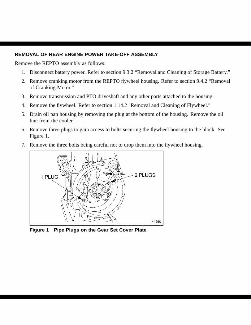
6. Remove three plugs to gain access to bolts securing the flywheel housing to the block. SeeFigure 1.
7. Remove the three bolts being careful not to drop them into the flywheel housing.
Figure 1 Pipe Plugs on the Gear Set Cover Plate
NOTICE:
Do not drop the bolt or washer into the gear set. Engine or REPTOdamage will occur.
FALLING COMPONENT
To avoid injury from a falling component, ensure a properlifting device is used.
8. Attach a suitable sling or use a floor jack to support the flywheel housing, which weighs about300 lbs. Remove the remaining eight bolts. Gently tap the backside of the flywheel housingwith a rubber mallet to loosen it from the block. Remove the housing.
To avoid injury from flying sealant. Do not use an impact gunon plugs with white sealant.
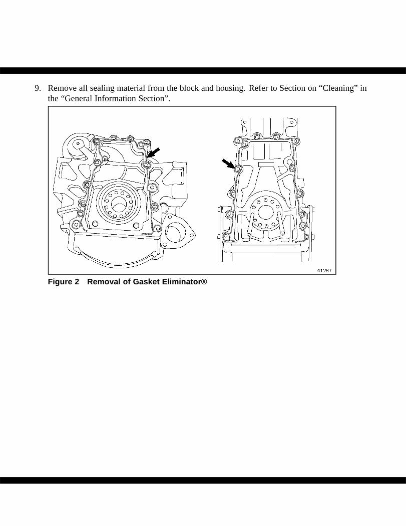
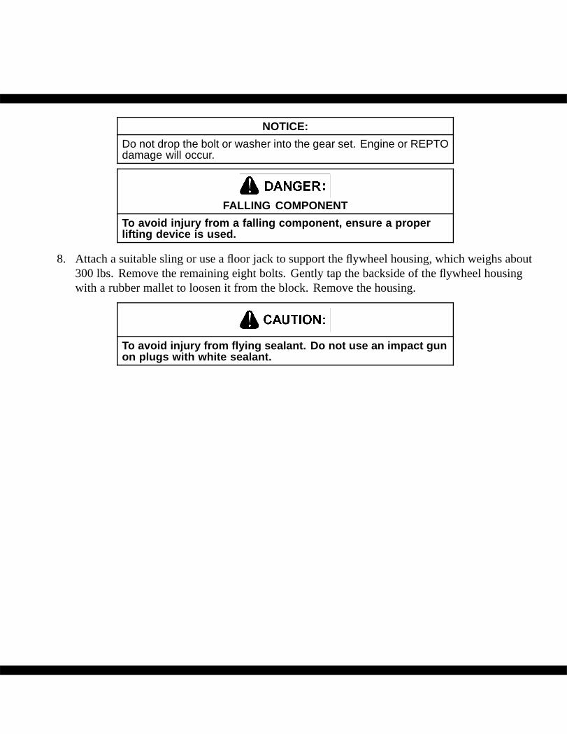
9. Remove all sealing material from the block and housing. Refer to Section on “Cleaning” inthe “General Information Section”.
Figure 2 Removal of Gasket Eliminator®
REMOVAL OF THE YOKE AND YOKE SEAL
Remove as follows:
1. Remove all dirt and debris, including any debris from the threaded end of the shaft, outsideof the nut.
NOTICE:
The nut has a prevailing torque. Be careful not to damage theoutput shaft as the nut is removed.
2. Remove the retaining nut while holding the yoke or flange stationary.
3. Remove the flat washer and the yoke.
4. Remove the seal being careful not to damage the cast iron case.
INSTALLATION OF YOKE AND SEALS
Install as follows:
1. Clean the seal bore diameter of all dirt and grease.
2. Clean the yoke seal diameter of all dirt and grease.
3. Ensure that the installation tools are also clean, scratch and burr-free.
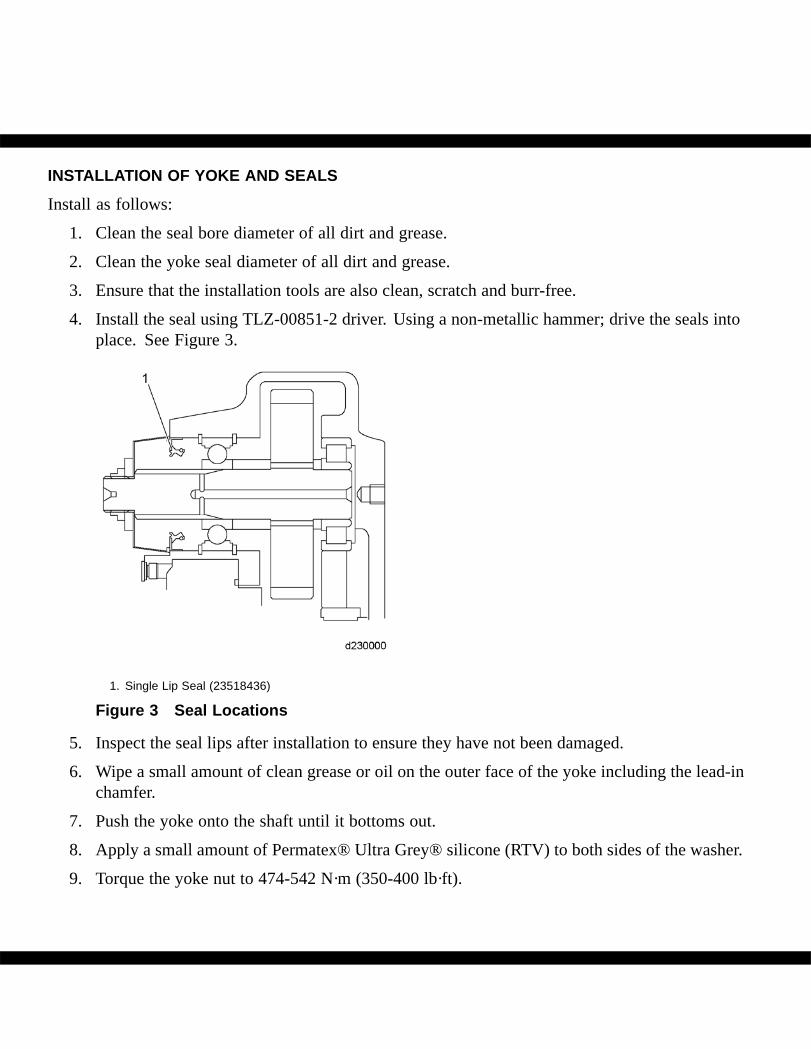
4. Install the seal using TLZ-00851-2 driver. Using a non-metallic hammer; drive the seals intoplace. See Figure 3.
1. Single Lip Seal (23518436)
Figure 3 Seal Locations
5. Inspect the seal lips after installation to ensure they have not been damaged.
6. Wipe a small amount of clean grease or oil on the outer face of the yoke including the lead-inchamfer.
7. Push the yoke onto the shaft until it bottoms out.
8. Apply a small amount of Permatex® Ultra Grey® silicone (RTV) to both sides of the washer.
9. Torque the yoke nut to 474-542 N·m (350-400 lb·ft).
INSTALLATION OF REAR ENGINE POWER TAKE-OFF ASSEMBLY
Install the REPTO as follows:
NOTE:Flywheel housing needs to be laying flat when installing tool.
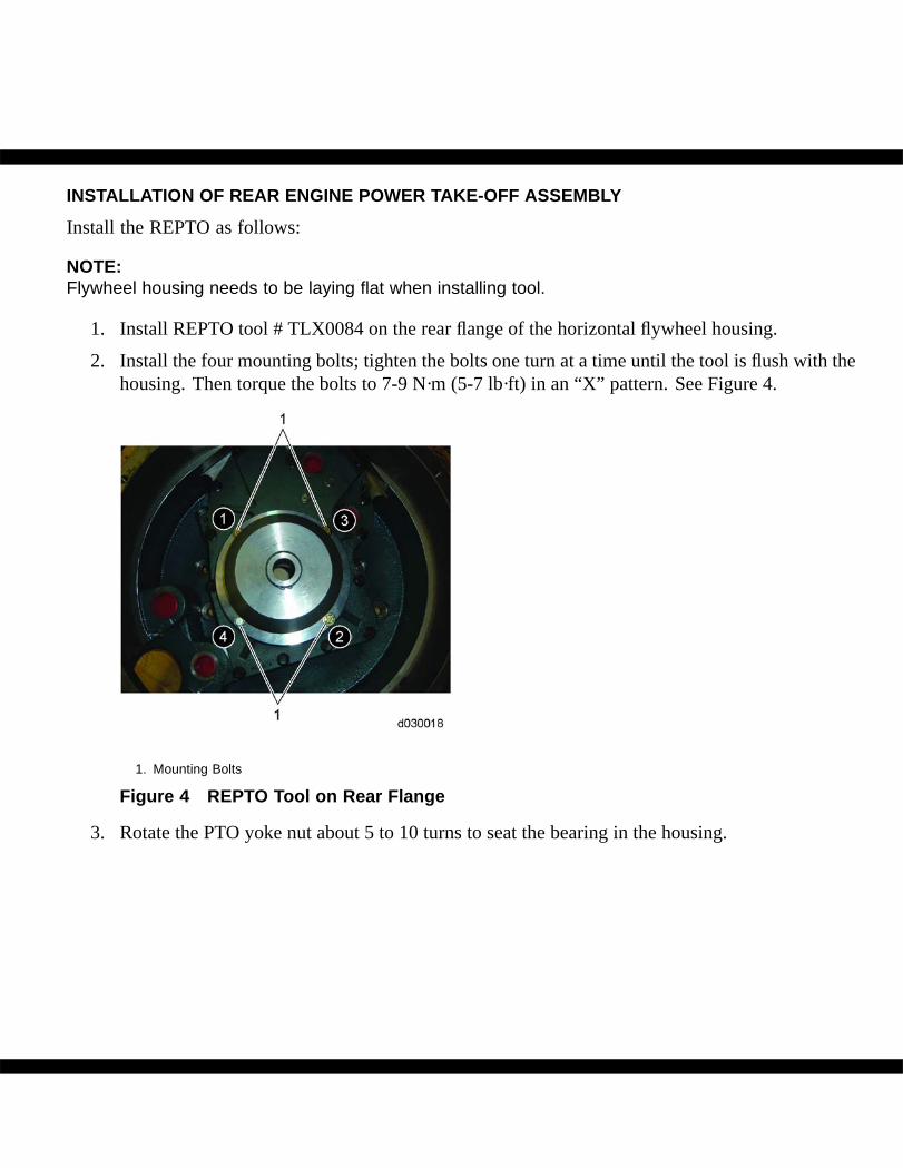
1. Install REPTO tool # TLX0084 on the rear flange of the horizontal flywheel housing.
2. Install the four mounting bolts; tighten the bolts one turn at a time until the tool is flush with thehousing. Then torque the bolts to 7-9 N·m (5-7 lb·ft) in an “X” pattern. See Figure 4.
1. Mounting Bolts
Figure 4 REPTO Tool on Rear Flange
3. Rotate the PTO yoke nut about 5 to 10 turns to seat the bearing in the housing.
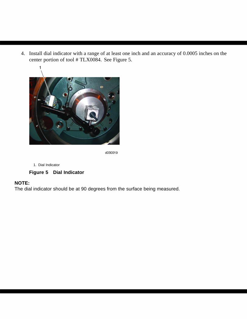
4. Install dial indicator with a range of at least one inch and an accuracy of 0.0005 inches on thecenter portion of tool # TLX0084. See Figure 5.
1. Dial Indicator
Figure 5 Dial Indicator
NOTE:The dial indicator should be at 90 degrees from the surface being measured.
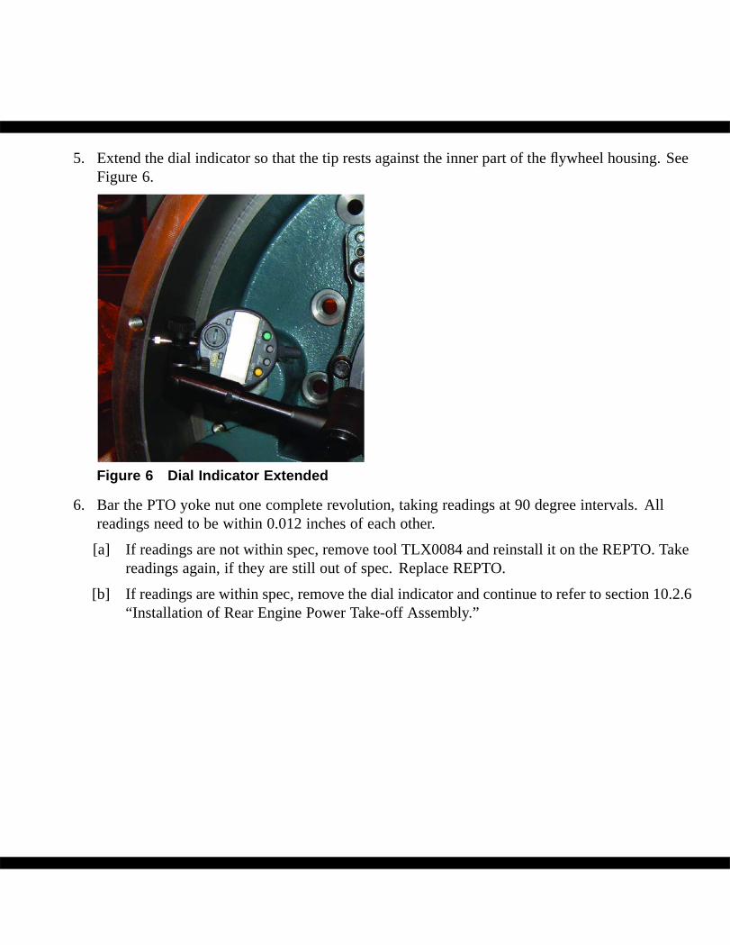
5. Extend the dial indicator so that the tip rests against the inner part of the flywheel housing. SeeFigure 6.
Figure 6 Dial Indicator Extended
6. Bar the PTO yoke nut one complete revolution, taking readings at 90 degree intervals. Allreadings need to be within 0.012 inches of each other.
[a] If readings are not within spec, remove tool TLX0084 and reinstall it on the REPTO. Takereadings again, if they are still out of spec. Replace REPTO.
[b] If readings are within spec, remove the dial indicator and continue to refer to section 10.2.6“Installation of Rear Engine Power Take-off Assembly.”
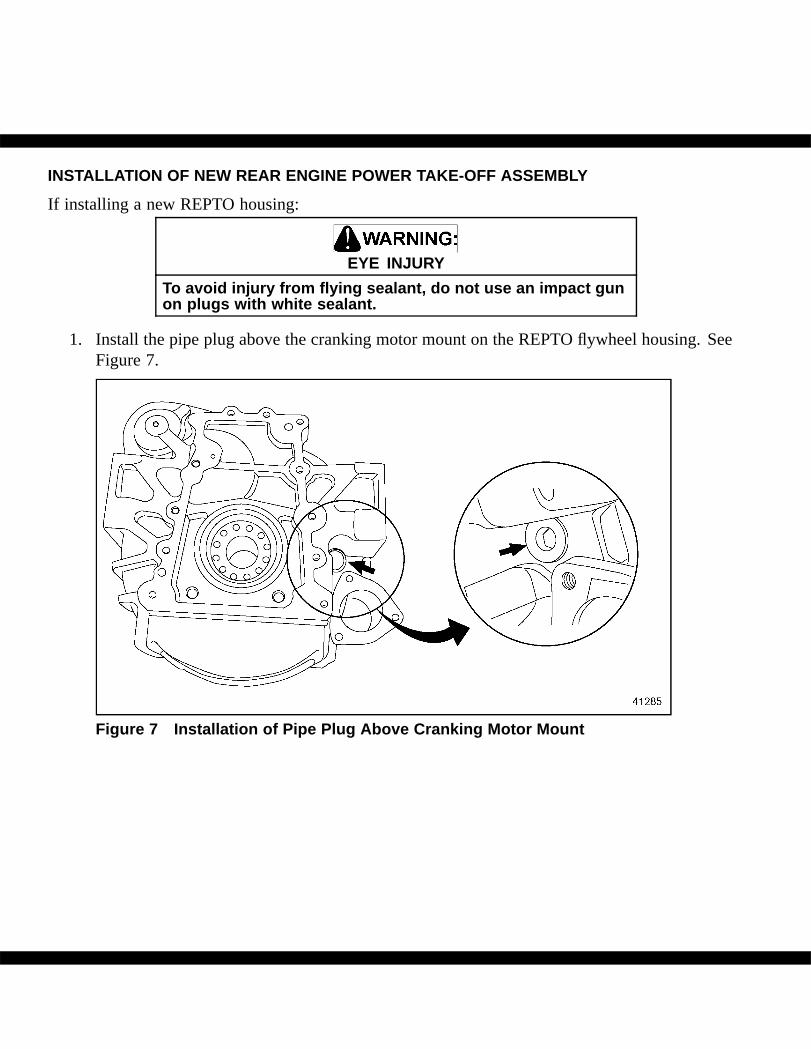
INSTALLATION OF NEW REAR ENGINE POWER TAKE-OFF ASSEMBLY
If installing a new REPTO housing:
EYE INJURY
To avoid injury from flying sealant, do not use an impact gunon plugs with white sealant.
1. Install the pipe plug above the cranking motor mount on the REPTO flywheel housing. SeeFigure 7.
Figure 7 Installation of Pipe Plug Above Cranking Motor Mount
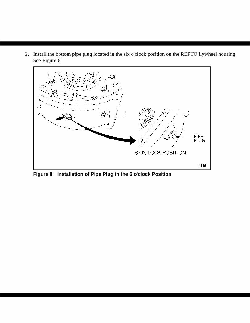
2. Install the bottom pipe plug located in the six o'clock position on the REPTO flywheel housing.See Figure 8.
Figure 8 Installation of Pipe Plug in the 6 o'clock Position
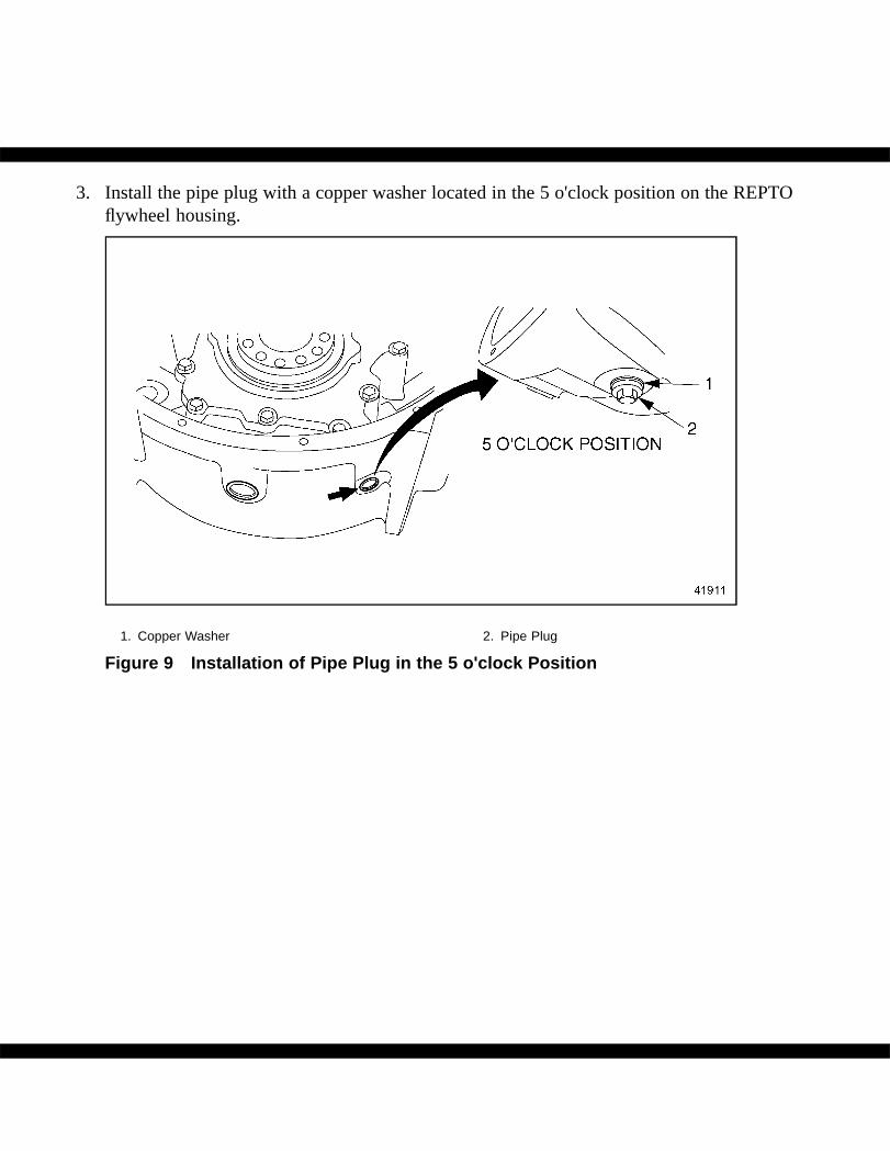
3. Install the pipe plug with a copper washer located in the 5 o'clock position on the REPTOflywheel housing.
1. Copper Washer 2. Pipe Plug
Figure 9 Installation of Pipe Plug in the 5 o'clock Position
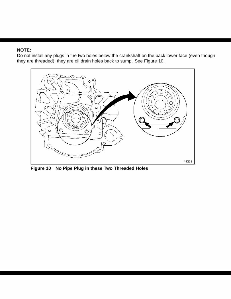
NOTE:Do not install any plugs in the two holes below the crankshaft on the back lower face (even thoughthey are threaded); they are oil drain holes back to sump. See Figure 10.
Figure 10 No Pipe Plug in these Two Threaded Holes
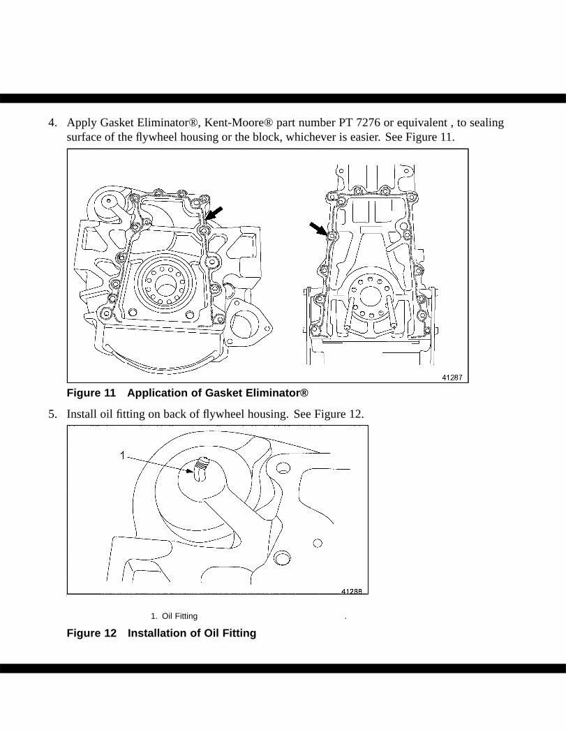
4. Apply Gasket Eliminator®, Kent-Moore® part number PT 7276 or equivalent , to sealingsurface of the flywheel housing or the block, whichever is easier. See Figure 11.
Figure 11 Application of Gasket Eliminator®
5. Install oil fitting on back of flywheel housing. See Figure 12.
1. Oil Fitting .
Figure 12 Installation of Oil Fitting
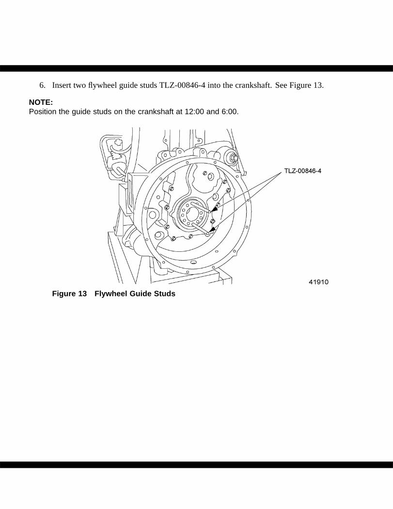
6. Insert two flywheel guide studs TLZ-00846-4 into the crankshaft. See Figure 13.
NOTE:Position the guide studs on the crankshaft at 12:00 and 6:00.
Figure 13 Flywheel Guide Studs
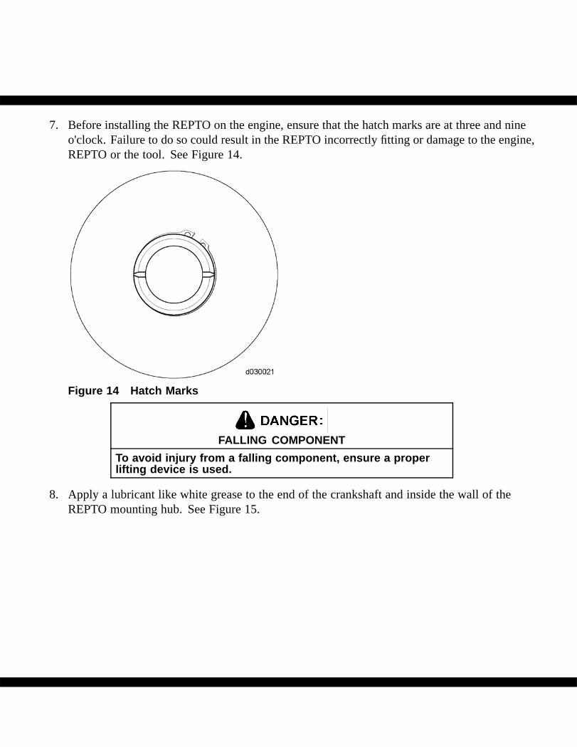
7. Before installing the REPTO on the engine, ensure that the hatch marks are at three and nineo'clock. Failure to do so could result in the REPTO incorrectly fitting or damage to the engine,REPTO or the tool. See Figure 14.
Figure 14 Hatch Marks
FALLING COMPONENT
To avoid injury from a falling component, ensure a properlifting device is used.
8. Apply a lubricant like white grease to the end of the crankshaft and inside the wall of theREPTO mounting hub. See Figure 15.
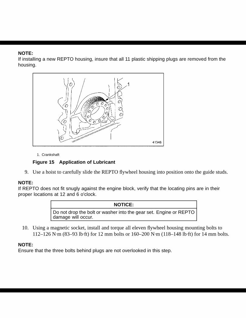
NOTE:If installing a new REPTO housing, insure that all 11 plastic shipping plugs are removed from thehousing.
1. Crankshaft
Figure 15 Application of Lubricant
9. Use a hoist to carefully slide the REPTO flywheel housing into position onto the guide studs.
NOTE:If REPTO does not fit snugly against the engine block, verify that the locating pins are in theirproper locations at 12 and 6 o'clock.
NOTICE:
Do not drop the bolt or washer into the gear set. Engine or REPTOdamage will occur.
10. Using a magnetic socket, install and torque all eleven flywheel housing mounting bolts to112–126 N·m (83–93 lb·ft) for 12 mm bolts or 160–200 N·m (118–148 lb·ft) for 14 mm bolts.
NOTE:Ensure that the three bolts behind plugs are not overlooked in this step.
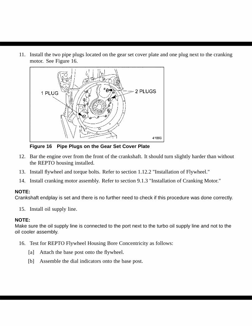
11. Install the two pipe plugs located on the gear set cover plate and one plug next to the crankingmotor. See Figure 16.
Figure 16 Pipe Plugs on the Gear Set Cover Plate
12. Bar the engine over from the front of the crankshaft. It should turn slightly harder than withoutthe REPTO housing installed.
13. Install flywheel and torque bolts. Refer to section 1.12.2 "Installation of Flywheel."
14. Install cranking motor assembly. Refer to section 9.1.3 "Installation of Cranking Motor."
NOTE:Crankshaft endplay is set and there is no further need to check if this procedure was done correctly.
15. Install oil supply line.
NOTE:Make sure the oil supply line is connected to the port next to the turbo oil supply line and not to theoil cooler assembly.
16. Test for REPTO Flywheel Housing Bore Concentricity as follows:
[a] Attach the base post onto the flywheel.
[b] Assemble the dial indicators onto the base post.
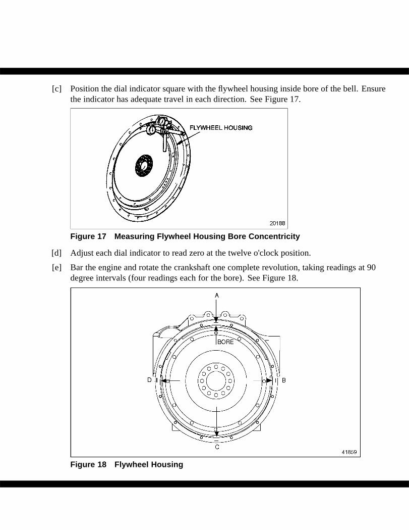
[c] Position the dial indicator square with the flywheel housing inside bore of the bell. Ensurethe indicator has adequate travel in each direction. See Figure 17.
Figure 17 Measuring Flywheel Housing Bore Concentricity
[d] Adjust each dial indicator to read zero at the twelve o'clock position.
[e] Bar the engine and rotate the crankshaft one complete revolution, taking readings at 90degree intervals (four readings each for the bore). See Figure 18.
Figure 18 Flywheel Housing
[f] Remove the wrench or cranking bar before recording each reading to ensure accuracy.
NOTE:The maximum total indicator reading must not exceed 0.33 mm (0.013 in.).
[g] If the run-out exceeds the maximum limits, check for dirt or foreign material between theflywheel housing and the cylinder block or oil pan.
[h] Clean the mating surfaces once again. Refer to section "General Information, Cleaning"in the beginning of this manual.
[i] Check run-out again.
17. Install transmission. Refer to OEM.
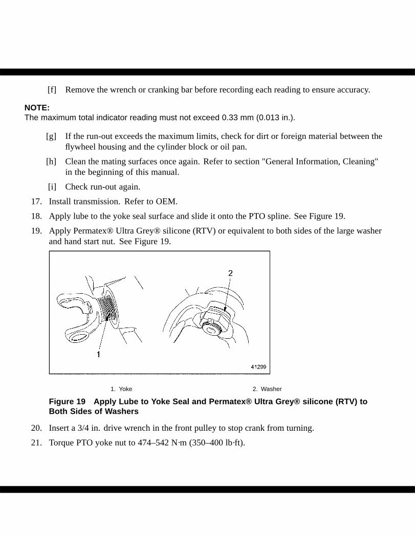
18. Apply lube to the yoke seal surface and slide it onto the PTO spline. See Figure 19.
19. Apply Permatex® Ultra Grey® silicone (RTV) or equivalent to both sides of the large washerand hand start nut. See Figure 19.
1. Yoke 2. Washer
Figure 19 Apply Lube to Yoke Seal and Permatex® Ultra Grey® silicone (RTV) toBoth Sides of Washers
20. Insert a 3/4 in. drive wrench in the front pulley to stop crank from turning.
21. Torque PTO yoke nut to 474–542 N·m (350–400 lb·ft).
NOTE:All cranking motors assembled to the REPTO housings should be installed with a new gasket.
22. Fill engine with clean lube oil.
23. Start and run engine for verification of proper engine operation.
ADDITIONAL SERVICE INFORMATION
Additional service information is available in Power Service Literature.
Detroit Diesel®, DDC®, Series 60® and the spinning arrows design are registered trademarks of Detroit Diesel Corporation.© Copyright 2009 Detroit Diesel Corporation. All rights reserved. Printed in U.S.A.