Embed Size (px)
Citation preview

I N F O R M A T I O N M A N U A L
E X T R A 3 0 0 L
MANUFACTURER
EXTRA Flugzeugproduktions- und Vertriebs- GmbHFlugplatz Dinslaken
46569 Hünxe, Federal Republic of Germany
TITLE PAGE
W A R N I N G
This is an Information Manual and may be used for general purposes only.
This Information Manual is not kept current.
It must not be used as a substitute for the official FAA/EASA Approved Pilot's OperatingHandbook required for operation of the airplane.

Left blank intentionally

Page Date: 31. March 2009 i
Pilot´s Operating HandbookEXTRA 300L
LOG OF REVISIONS
Dates of issue for original and revised pages:
Original ......................... 9. September 1994
Revision No. 1 ....................... 26. June 1997
Revision No. 2 .........................7. June 1999
Edition No. 2 ......................... 20. April 2002
Rev. No. 1, 2nd Ed. ...... 15. December 2005
Rev. No. 2, 2nd Ed. ..... 20. September 2006
Rev. No. 3, 2nd Ed. .................6. June 2008
Rev. No. 4, 2nd Ed. ........ 5. December 2008
Rev. No. 5, 2nd Ed. ............ 16. March 2009
Rev. No. 6, 2nd Ed. ............ 31. March 2009
Rev. No. 7, 2nd Ed. ..........08. October 2009
Rev. No. 8, 2nd Ed. ............... 19. April 2012
Rev. No. 9, 2nd Ed. .......... 17. January 2013
Rev. No. 10, 2nd Ed. ........ 31. October 2013
Rev. No. 11, 2nd Ed. ........ 20. January 2016
Date and sign of approval:
LBA approved ................... 31. January 1995
LBA approved .................... 27. August 1997
LBA approved ........................ 23. June 1999
LBA approved ...................30. October 2002
EASA Approval N° ......... EASA.A.A.01101Date of Approval ........... 20. December 2005
EASA Approval N° ......... EASA.A.A.01319Date of Approval ............ 20. November 2006
EASA Approval N° ......... EASA.A.C.08351Date of Approval ..................... 24. July 2008
EASA Approval N° ......... EASA.A.C.10781Date of Approval ............. 18. February 2009
Approved under the authority of DOAN° EASA.21J.073 (ECO: ÄM-300-09-07)Date of Approval ...................... 6. April 2009
EASA Approval N° ..................... 10026766Date of Approval .................. 7. August 2009
Approved under the authority of DOAN° EASA.21J.073 (FAA Validation ProcessTD0306CE-A; P-EASA.CSV.A.01467)Date of Approval ............... 14. October 2009
Approved under the authority of DOAN° EASA.21J.073 (ANAC ValidationProcess; EASA Project N° 0010011276)Date of Approval ............... 08. October 2012
Approved under the authority of DOAN° EASA.21J.073 (ECO: ÄM-300-12-13)Date of Approval ................. 04.March 2013
Approved under the authority of DOAN° EASA.21J.073 (ANAC ValidationProcess & ECO: ÄM-300-12-13, ÄM-300-13-03, ÄM-300-13-08)Date of Approval ............ 14. November 2013
Approved under the authority of DOAN° EASA.21J.073Date of Approval ................. 11. March 2016
Page Date: 20. January 2016

ii Page Date: 31. March 2009
Pilot´s Operating HandbookEXTRA 300L
Page Date
Title .................................... 31. March 2009i thru iii ............................. 20. January 2016iv ........................................... 19. April 2012v....................................... 20. January 2016vi ........................................ 31. March 20091-1 ..................................... 16. March 20091-2 ........................................ 20. April 20021-3 ..................................... 31. March 20091-4 ........................................ 19. April 20121-5 ..................................... 31. March 20091-6 ........................................ 20. April 20021-7 ..................................... 31. March 20091-8 ..................................... 16. March 20092-1 ................................... 20. January 20162-2 ........................................ 20. April 20022-3 ..................................... 31. March 20092-4 ................................... 20. January 20162-5 .....................................8. October 20092-6 thru 2-8 ...................... 20. January 20162-9 ..................................... 16. March 20092-10 ............................. 15. December 20052-11 ................................... 16. March 20092-12 ...................................... 19. April 20122-13 ............................. 15. December 20052-14 ................................. 20. January 20163-1 thru 3-2 ........................... 20. April 20023-3 ................................... 20. January 20163-4 ..................................... 16. March 20093-5 thru 3-6 ...................... 20. January 20163-7 ..................................... 16. March 20093-8 ..................................... 31. March 20094-1 ................................... 20. January 20164-2 ........................................ 20. April 20024-3 thru 4-4 ........................... 19. April 20124-5 thru 4-6 ........................... 20. April 20024-7 ................................... 20. January 20164-8 ..................................... 31. March 20094-9 ..................................... 16. March 20094-10 thru 4-12 ................... 20. January 20165-1 thru 5-2 ........................... 20. April 20025-3 thru 5-4 ........................ 16. March 20095-5 ........................................ 20. April 20025-6 thru 5-9 ........................ 16. March 20095-10 thru 5-12 ........................ 20. April 20025-13 ................................. 20. January 20165-14 ................................... 16. March 20096-1 thru 6-2 ........................... 20. April 20026-3 .............................. 20. September 20066-4 ..................................... 31. March 20096-5 thru 6-6 ........................... 20. April 20026-7 ..................................... 31. March 20096-8 ........................................ 20. April 2002
LOG OF EFFECTIVE PAGES
6-9 thru 6-16 ..................... 20. January 20167-1 .............................. 20. September 20067-2 ........................................ 20. April 20027-3 thru 7-4 ........................ 31. March 20097-5 thru 7-8 ........................... 20. April 20027-9 ..................................... 31. March 20097-10 ............................. 15. December 20057-11 ................................. 20. January 20167-12 thru 7-13 ............... 15. December 20057-14 ................................... 8. October 20097-15 thru 7-16 ........................ 20. April 20028-1 thru 8-4 ........................... 20. April 20029-1 ................................. 5. December 20089-2 ................................... 20. January 20169-3 ..................................... 31. March 20099-4 ........................................ 20. April 2002901-1 thru 901-4 .................... 20. April 2002902-1 thru 902-3 .................... 20. April 2002902-4 ..................................8. October 2009903-1 thru 903-10 .................. 20. April 2002904-1 thru 904-4 .................... 20. April 2002904-5 ................................ 20. January 2016904-6 thru 904-8 .................... 20. April 2002905-1 ................................ 20. January 2016905-2 ..................................... 20. April 2002905-3 thru 905-5 ............... 20. January 2016905-6 ..................................... 20. April 2002906-1 thru 906-2 .................... 20. April 2002906-3 thru 906-6 .................... 19. April 2012907-1 .................................. 16. March 2009907-2 thru 907-3 .................... 20. April 2002907-4 .................................. 16. March 2009907-5 ................................ 20. January 2016907-6 thru 907-6 ................. 16. March 2009908-1 thru 908-2 .................... 20. April 2002908-3 ................................ 20. January 2016908-4 .................................. 16. March 2009908-5 ................................ 20. January 2016908-6 thru 908-8 ................. 16. March 2009909-1 ................................ 20. January 2016909-2 ..................................... 20. April 2002909-3 thru 909-8 ............... 20. January 2016910-1 thru 910-2 .................... 20. April 2002910-3 thru 910-5 ................. 16. March 2009910-6 thru 910-8 .................... 20. April 2002911-1 thru 911-2 .................... 20. April 2002911-3 .................................. 31. March 2009911-4 ..................................... 20. April 2002912-1 thru 912-6 ........... 15. December 2005912-7 ................................ 20. January 2016912-8 ............................ 15. December 2005913-1 thru 913-6 ........... 15. December 2005
Page Date
Page Date: 20. January 2016

Page Date: 31. March 2009 iii
Pilot´s Operating HandbookEXTRA 300L
913-7 ................................ 20. January 2016913-8 ............................ 15. December 2005914-1 thru 914-2 ........... 15. December 2005914-3 ................................ 20. January 2016914-4 thru 914-6 ........... 15. December 2005915-1 thru 915-2 ........... 15. December 2005915-3 ................................ 20. January 2016915-4 .............................. 5. December 2008915-5 ............................ 15. December 2005915-6 .............................. 5. December 2008915-7 thru 915-8 ........... 15. December 2005916-1 thru 916-2 ........... 15. December 2005916-3 .................................. 31. March 2009916-4 thru 916-6 ........... 15. December 2005917-1 thru 917-2 ................. 31. March 2009917-3 ................................ 20. January 2016917-4 thru 917-8 ................. 31. March 2009918-1 thru 918-3 ........... 15. December 2005918-4 thru 918-5 ............... 20. January 2016918-6 ............................ 15. December 2005919-1 thru 919-3 ........... 15. December 2005919-4 ................................ 20. January 2016919-5 thru 919-8 ........... 15. December 2005920-1 thru 920-3 ................. 31. March 2009920-4 ................................ 20. January 2016920-5 thru 920-10 ............... 31. March 2009921-1 ................................ 20. January 2016921-2 .............................. 5. December 2008921-3 ..................................8. October 2009921-4 thru 921-5 ............... 20. January 2016921-6 ..................................... 19. April 2012921-7 ................................ 20. January 2016921-8 thru 921-9 .................... 19. April 2012921-10 .............................. 20. January 2016921-11 thru 921-16 ................ 19. April 2012922-1 thru 922-3 ............. 5. December 2008922-4 ................................ 20. January 2016922-5 thru 922-8 ............. 5. December 2008923-1 thru 923-2 ............. 5. December 2008923-3 ................................ 20. January 2016923-4 thru 923-8 ............. 5. December 2008924-1 thru 924-2 ................. 31. March 2009924-3 ................................ 20. January 2016924-4 thru 924-11 ............... 31. March 2009924-12 .............................. 31. October 2013925-1 thru 925-8 ................. 31. March 2009926-1 thru 926-1 ................. 31. March 2009926-3 ..................................... 19. April 2012926-4 .................................. 31. March 2009926-5 ..................................... 19. April 2012926-6 ................................ 20. January 2016926-7 thru 926-8 ................. 31. March 2009
Page Date
Page Date: 20. January 2016
927-1 ................................ 31. October 2013927-2 ..................................... 19. April 2012927-3 ................................ 31. October 2013927-4 thru 927-6 .................... 19. April 2012928-1 thru 928-4 ............... 17. January 2013929-1 thru 929-16 ............. 20. January 2016
Page Date

iv Page Date: 31. March 2009
Pilot´s Operating HandbookEXTRA 300L
INTRODUCTION
This handbook contains 9 sections, and includes the material required to be furnished to thepilot by FAR Part 23. It also contains supplementary data supplied by EXTRA Flugzeug-produktions- und Vertriebs- GmbH.
THIS MANUAL IS FURNISHED TO THE CIVIL AVIATION AUTHORITIES AS A PART OF THECERTIFICATION MATERIAL FOR THIS MODEL.
NOTES
This Flight Manual applies only to the aircraft whose nationality and registration marks arenoted on the title page.
This Flight Manual is only valid in connection with the latest approved revision. Refer to theEXTRA Homepage (direct link: http://www.extraaircraft.com/techservice.php), where the POHRevision Index always shows the current revision status.
It is the responsibility of the pilot to be familiar with the contents of this Flight Manualincluding revisions and any relevant supplements.
Pages of this Airplane Flight Manual must not be exchanged and no alterations of oradditions to the approved contents may be made without the EXTRA Flugzeugproduktions-und Vertriebs- GmbH/EASA approval.The editor has the copyright of this Flight Manual and is responsible for edition of revisions/amendments and supplements.
Amendments, which affect the airworthiness of the aircraft will be announced in themandatory Service Bulletins issued by the manufacturer EXTRA Flugzeugproduktions- undVertriebs- GmbH coming along with the "Airworthiness Directive" (AD) publication issued bythe EASA. The owner is responsible for incorporating prescribed amendments and shouldmake notes about these on the records of amendments.
Should this Flight Manual get lost, inform EXTRA Flugzeugproduktions- und Vertriebs- GmbH,Flugplatz Dinslaken 46569 Hünxe, Federal Republic of Germany.
Should this Flight Manual be found, kindly forward it to the civil board of aviation in the countrythe aircraft is registered.
Page Date: 19. April 2012

Page Date: 31. March 2009 v
Pilot´s Operating HandbookEXTRA 300L
NOTES AND SAFETY NOTES
Safety notes in this manual are marked by a boxed textmarker in the middle of the page and writtenin semi-bold characters. This manual distinguishes three warning levels:
D A N G E R
Indicates a hazardous situation which, if not avoided, will result in death or seriousinjury.
W A R N I N G
Indicates a hazardous situation which, if not avoided, could result in death or seriousinjury.
C A U T I O N
Indicates a hazardous situation which, if not avoided, could result in minor or mode-rate injury.
Additional information given in this manual are also marked by boxed textmarkers in the middleof the page and are written in semi-bold characters:
N O T I C E
Is used to address practices not related to physical injury.
N O T E
Represents an useful or remarkable hint.
TERMINOLOGIE
The words "shall", "must" or "will" are used to express a mandatory requirement.
The word "should" is used to express nonmandatory provisions.
The word "may" is used to express permissible.
Page Date: 20. January 2016

vi Page Date: 31. March 2009
Pilot´s Operating HandbookEXTRA 300L
MAIN TABLE OF CONTENTS
Section Page
1 GENERAL 1-1
2 LIMITATIONS 2-1
3 EMERGENCY PROCEDURES 3-1
4 NORMAL PROCEDURES 4-1
5 PERFORMANCE 5-1
6 WEIGHT & BALANCE/EQUIPMENT LIST 6-1
7 AIRPLANE & SYSTEMS DESCRIPTIONS 7-1
8 AIRPLANE HANDLING, SERVICE & MAINTENANCE 8-1
9 SUPPLEMENTS 9-1

Page Date: 20. April 2002 1 - 1
Pilot´s Operating HandbookEXTRA 300L
Section 1General
SECTION 1
GENERAL
Table of Contents
Paragraph PageSECTION 1 GENERAL
1.0 DESCRIPTION ....................................................................................................................... 1-3
1.1 SPECIFICATION OF CLASS ................................................................................................. 1-3
1.2 MANUFACTURER .................................................................................................................. 1-3
1.3 TECHNICAL DATA................................................................................................................. 1-31.3.1 3-View Drawing ...................................................................................................................... 1-31.3.2 Main Data ............................................................................................................................... 1-31.3.3 Wing ...................................................................................................................................... 1-41.3.4 Horizontal Tail ......................................................................................................................... 1-41.3.5 Elevator .................................................................................................................................. 1-41.3.6 Vertical Tail ............................................................................................................................. 1-41.3.7 Rudder ................................................................................................................................... 1-4
1.4 ENGINE.................................................................................................................................. 1-4
1.5 PROPELLER ......................................................................................................................... 1-51.5.1 Exhaust Systems (Optional) .................................................................................................. 1-5
1.6 FUEL ...................................................................................................................................... 1-5
1.7 OIL ......................................................................................................................................... 1-5
1.8 LOADING............................................................................................................................... 1-6
1.9 TERMINOLOGY ..................................................................................................................... 1-6
1.10 SECONDARY TERMINOLOGY .............................................................................................. 1-7
1.11 CONVERSION TABLE ........................................................................................................... 1-8
Page Date: 16. March 2009

1 - 2 Page Date: 20. April 2002
Section 1General
Pilot´s Operating HandbookEXTRA 300L
Left blank intentionally

Page Date: 20. April 2002 1 - 3
Pilot´s Operating HandbookEXTRA 300L
Section 1General
1.0 DESCRIPTION
The airframe of the EXTRA 300L is built of a tig-welded steel-tube construction. Wings,empennage and landing gear are manufactured of composite material.
The aircraft is a two-seater with the rear seat instrumented for pilot in comand.
1.1 SPECIFICATION OF CLASS
The aircraft is certified in normal and acrobatic category (T.C.D.S. EASA.A.362).
1.2 MANUFACTURER
EXTRA Flugzeugproduktions- und Vertriebs- GmbH,Flugplatz Dinslaken46569 Hünxe,Federal Republic of Germany.
1.3 TECHNICAL DATA
1.3.1 3-VIEW DRAWING
Page Date: 31. March 2009

1 - 4 Page Date: 20. April 2002
Section 1General
Pilot´s Operating HandbookEXTRA 300L
1.3.2 MAIN DATA
- Length 6,96 m (22,83 ft)- Height 2,62 m ( 8,60 ft)- Span 8,00 m (26,25 ft)- Wheel-base 5,07 m (16,63 ft)- Wheel-track 1,80 m ( 5,91 ft)
1.3.3 WING
- Wing span 8,0 m (26,25 ft)- Wing-area 10,7 m² (115,17 ft²)- Airfoil Root: MA 15 S. Tip, MA 12 S- Chord Root: 1,85 m. Tip, 0,88 m- MAC 1,404 m ( 4,61 ft)- Aileron area 2 x 0,855 m² (2 x 9,20 ft²)- Aileron deflection up/down 30°, tolerance ± 2°
1.3.4 HORIZONTAL TAIL
- Span 3,20 m (10,50 ft)- Area 2,56 m² (27.56 ft²)- Airfoil Wortmann FX 71-L-150/30
1.3.5 ELEVATOR
- Area 0,77 m² (8,29 ft²)- Elevator-deflection up/down 25°, tolerance ±2°- Trim-tab-deflection up 40°, down 50°, tolerance ±5°
1.3.6 VERTICAL TAIL
- Area 1,39 m² (14,96 ft²)- Airfoil Wortmann FX 71-L-150/30
1.3.7 RUDDER
- Area 0,51 m² ( 5,49 ft²)- Rudder deflection left/right 30°, tolerance ±2°
Page Date: 19. April 2012

Page Date: 20. April 2002 1 - 5
Pilot´s Operating HandbookEXTRA 300L
Section 1General
1.4 ENGINE
Manufacturer: Textron-Lycoming Williamsport Plant PA 17701 USA.a) Type Lycoming AEIO-540-L1B5b) Type Lycoming AEIO-540-L1B5D
Rated power: 300 HP @ 2700 RPM; 270 HP @ 2400 RPM
1.5 PROPELLER
Manufacturer: MT-Propeller Entwicklung GmbH, Federal Republic of Germany.a) Type MTV-9-B-C/C 200-15 3-blade constant speed.b) Type MTV-14-B-C/C 190-17 4-blade constant speed.
1.5.1 EXHAUST SYSTEMS (OPTIONAL)
Manufacturer: Gomolzig Flugzeug- und Maschinenbau GmbH, Federal Republic of GermanyExhaust Silencer for standard system: PN: EA 300 NSD GO3-606500.Complete 6 in 1 System with integrated Silencer: PN: EA 300-606000
1.6 FUEL
Fuel type AVGAS 100/100 LL (for alternate fuel grades see later issues of Textron LycomingS.I. No 1070)Minimum 100/130 octane. Maximum 115/145 octane.
Total fuel capacity: 171 L (45.1 US.gal) - Wingtanks (2 x 60 L): 120 L (31.7 US.gal) - Acro & center tank: 51 L (13.4 US.gal)
Usable fuel capacity in the system: 165.5 L (43.7 US.gal)Usable fuel capacity for acrobatic: 45.5 L (12.0 US.gal)
1.7 OIL
Maximum sump capacity: 16 US.qtMinimum sump capacity: 9 US.qt
Average ambient air Mil-L6082 Mil-22851temperature grades ashless dispersant grades
All temperatures ---- SAE 15W50 or 20W50
> 27°C (80°F) SAE 60 SAE 60
> 16°C (60°F) SAE 50 SAE 40 or 60
- 1°C til 32°C SAE 40 SAE 40 (30°F - 90°F)
Page Date: 31. March 2009

1 - 6 Page Date: 20. April 2002
Section 1General
Pilot´s Operating HandbookEXTRA 300L
1.7 OIL (Cont.)
Average ambient air Mil-L6082 Mil-22851temperature grades ashless dispersant grades
- 18°C til 21°C SAE 30 SAE 30,40 or 20W40 (0°F - 70°F)
- 18°C til 32°C SAE 20W50 SAE 20W50 or 15W50 (0°F - 90°F)
< -12°C (10°F) SAE 20 SAE 30 or 20W30
(single or multi - viscosity aviation grade oils see latest issue of Textron Lyc. S.I. No. 1014)
1.8 LOADING
Wing loading 88,8 kg/m² Normal76,6 / 81,3 kg/m² Acrobatic (1 seat / 2 seats)
Power loading 3,17 kg/hp Normal2.73 / 2.90 kg/hp Acrobatic (1 seat / 2 seats)
1.9 TERMINOLOGY
Air Speeds
CAS Calibrated Air Speed. CAS is the same as TAS(True Air Speed) in standard atmospheric condition at sea level
KCAS Calibrated speed in knots
GS Ground speed
IAS Indicated air speed
KIAS Indicated speed in knots
TAS True air speed. It's the same as CAS compensated for altitude,temperature and density
VA Maneuvering speed
VNE Never exceed speed
VNO Maximum structural crusing speed
VS Stalling speed or minimum steady flight speed
VX Best angle-of-climb speed
VY Best rate-of-climb speed

Page Date: 20. April 2002 1 - 7
Pilot´s Operating HandbookEXTRA 300L
Section 1General
Meteorological terminology
ISA International standard atmospheric condition
OAT Outside air temperature
1.10 SECONDARY TERMINOLOGY
fpm Feet/minute
ft Feet = 0.3048 m
in inch = 2.54 cm
m Meter
L Litres
US.gal US (liquid) gallon = 3.79 litres
US.qt US (liquid) quart = 0.946 litres
hp Horse power (english)
h Hour
kts Knots (nm/h) = 1.852 kilometer per hour
km/h Kilometer per hour
lbs English pound = 0.4536 kg
hPa hekto Pascal
inHg Inches of mercury
MP Manifold pressure
PA Pressure altitude (ft)
nm Nautical miles = 1.852 km
rpm Revolutions per minute
CG Center of gravity
Arm Arm is the horizontal distance from reference datum
Moment is the product of weight of an item multiplied by its arm.
Page Date: 31. March 2009

1 - 8 Page Date: 20. April 2002
Section 1General
Pilot´s Operating HandbookEXTRA 300L
1.11 CONVERSION TABLE
Page Date: 16. March 2009

Page Date: 20. April 2002 2 - 1
Pilot´s Operating HandbookEXTRA 300L
Section 2Limitations
SECTION 2
LIMITATIONS
Table of Contents
Paragraph PageSECTION 2 LIMITATIONS
2.1 GENERAL ........................................................................................................................... 2-3
2.2 AIR SPEED (IAS) ............................................................................................................... 2-3
2.3 CROSS-WIND COMPONENT............................................................................................. 2-3
2.4 ENGINE .............................................................................................................................. 2-32.4.1 Fuel ..................................................................................................................................... 2-42.4.2 Engine Limitations ............................................................................................................... 2-4
2.5 PROPELLER ...................................................................................................................... 2-5
2.6 WEIGHT LIMITS ................................................................................................................. 2-5
2.7 WEIGHT AND C.G. ENVELOPE ......................................................................................... 2-52.7.1 Normal Flight ....................................................................................................................... 2-52.7.2 Acrobatic Flight (1 Seat) ...................................................................................................... 2-52.7.3 Acrobatic Flight (2 Seats) .................................................................................................... 2-6
2.8 ACROBATIC MANEUVERS ................................................................................................ 2-62.8.1 Normal Flight ....................................................................................................................... 2-62.8.2 Acrobatic Flight .................................................................................................................... 2-6
2.9 LOAD FACTOR................................................................................................................... 2-72.9.1 Normal Flight ....................................................................................................................... 2-72.9.2 Acrobatic Flight .................................................................................................................... 2-8
2.10 FLIGHT CREW LIMITS ...................................................................................................... 2-8
2.11 KINDS OF OPERATIONAL LIMITS .................................................................................... 2-82.11.1 Structural Temperature/Colour Limitation............................................................................. 2-8
2.12 MAXIMUM OPERATING ALTITUDE ................................................................................... 2-8
2.13 TIRE PRESSURE ............................................................................................................... 2-8
2.14 MARKINGS AND PLACARDS ............................................................................................ 2-82.14.1 Aircraft Identity Placards ...................................................................................................... 2-82.14.2 Operating Placards .............................................................................................................. 2-92.14.3 Instrument Markings .......................................................................................................... 2-12
2.15 KINDS OF OPERATION EQUIPMENT LIST .......................................................................2-13
Page Date: 20. January 2016

2 - 2 Page Date: 20. April 2002
Pilot´s Operating HandbookEXTRA 300L
Section 2Limitations
Left blank intentionally

Page Date: 20. April 2002 2 - 3
Pilot´s Operating HandbookEXTRA 300L
Section 2Limitations
SECTION 2
LIMITATIONS
2.1 GENERAL
This section includes operating limitations, instrument markings, and basic placardsnecessary for the safe operation of the aircraft, its engine, standard systems, and standardequipment. The limitations included in this section have been approved by the EASA.Observance of these operating limitations is required by national aviation regulations.
N O T E
In case of an aircraft equipped with specific options additional information requiredfor safe operation will be contained in Section 9 "Supplements".
Instrument markings and placards are provided for the acrobatic category only; for normalcategory refer to corresponding limitations. This aircraft is certified under Type CertificationData Sheet (T.C.D.S. EASA.A.362).
Any exceedance of given limitations has to be reported by the pilot so that necessaryinspection or maintenance procedures according to the SERVICE MANUAL EA 300/L can beperformed .
2.2 AIR SPEED (IAS)
Never Exceed Speed VNE 220 knots (407 km/h)Max. Structural Cruising Speed (Normal Cat.) VNO 140 knots (259 km/h)Max. Structural Cruising Speed (Acro I , Acro II) VNO 158 knots (293 km/h)Maneuver Speed (Normal Cat.) VA 140 knots (259 km/h)Maneuver Speed (Acro I , Acro II) VA 158 knots (293 km/h)
2.3 CROSS-WIND COMPONENT
Max. demonstrated cross-wind component for take-off and landing is 15 knots (27 km/h).
2.4 ENGINE
Engine-type Textron-Lycoming AEIO-540-L1B5 / AEIO-540-L1B5D with rated maximum300 HP @ 2700 RPM.
Page Date: 31. March 2009

2 - 4 Page Date: 20. April 2002
Pilot´s Operating HandbookEXTRA 300L
Section 2Limitations
2.4.1 FUEL
Minimum grade aviation gasoline: 100/100LL; for alternate fuelgrades seelatest revision of Lyc. S.I. No. 1070Total fuel capacity: 171 L (45.1 US.gal).Usable fuel capacity: 165.5 L (43.6 US.gal).For acrobatic flight wing tanks must be empty.Total fuel capacity for acrobatic: 51 L (13.4 US.gal) in acro & center tank.Usable fuel capacity for acrobatic: 45.5 L (12.0 US.gal) in acro & center tank.
2.4.2 ENGINE LIMITATIONS
a) Rotational Speed
-Maximum Take-Off and Maximum Continuous 2700 rpm
b) Oil-temperature
-Max 118°C 245°F
c) Oil capacity
-Maximum sump capacity: 15.13 L 16 US.qt-Minimum sump capacity: 8.51 L 9 US.qt
d) Oil pressure
-Minimum Idling 172 kPa 25 Psi-Normal 379 - 655 kPa 55 - 95 Psi-Starting,Warm up, Taxi and Take-Off 793 kPa 115 Psi
W A R N I N G
It is normal for the oil pressure to "flicker" from 10 to 30 psi (69 to 207 kPa) whengoing from upright to inverted flight. During knife edge flights and zero-g flights oilpressure may drop and the oil system may not scavenge resulting in engine failureor damage if flight is prolonged.Knife edge and zero-g flight should not exceed 10 seconds.
W A R N I N G
If oil pressure drops to 0 psi (kPa) the propeller pitch changes automatically tocoarse (high) pitch with a corresponding decrease in RPM.Apply positive g to avoid engine stoppage.
e) Fuel pressure
-Max 276 kPa 40 Psi-Min 124 kPa 18 Psi-Min Idle 83 kPa 12 Psi
Page Date: 20. January 2016

Page Date: 20. April 2002 2 - 5
Pilot´s Operating HandbookEXTRA 300L
Section 2Limitations
f) Cylinder head temperature
-Max 260°C 500°F
2.5 PROPELLER
MT-Propeller Entwicklung GmbH, Federal Republic of Germanya) Type MTV-14-B-C/C190-17
-Maximum Take-Off and Maximum Continuous 2700 rpm
b) Type MTV-9-B-C/C200-15-Maximum Take-Off (5 min) 2700 rpm-Maximum Continuous 2400 rpm*
N O T E*
RPM limitation due to compliance with applicable noise protection requirements(FAR 36). However for non-US registered airplanes an enhanced rotational speedlimitation of 2700 RPM may be permissable when registered in the AcrobaticCategory only as ICAO Annex 16 grants an exception for airplanes speciallydesigned for acrobatic purposes.
2.6 WEIGHT LIMITS
Max allowed empty weight:-Normal category 745 kg (1643lbs)-Acrobatic category ( 1 seat) 701 kg (1546lbs)
( 2 seats) 665 kg (1466lbs)Max allowed T/O weight:
-Normal category 950 kg (2095 lbs)-Acrobatic category ( 1 seat) 820 kg (1808 lbs)
( 2 seats) 870 kg (1918 lbs)Max allowed landing weight: 950 kg (2095 lbs)
2.7 WEIGHT AND C.G. ENVELOPE
Vertical reference = fire-wall.Horizontal reference = upper longerons in cockpit.
2.7.1 NORMAL FLIGHT
Max T/O Weight: forward C.G. rear C.G.
950 kg (2095 lbs) 67.1 cm (26.4") 84.1 cm (33.1")(and below)
2.7.2 ACROBATIC FLIGHT (1 SEAT)
Max T/O Weight: forward C.G. rear C.G.820 kg (1808 lbs) 67.1 cm (26.4") 84.1 cm (33.1")(and below)
Page Date: 5. December 2008Page Date: 8. October 2009

2 - 6 Page Date: 20. April 2002
Pilot´s Operating HandbookEXTRA 300L
Section 2Limitations
2.7.3 ACROBATIC FLIGHT (2 SEATS)
Max T/O Weight: forward C.G. rear C.G.
870 kg (1918 lbs) 67.1 cm (26.4") 84.1 cm (33.1")(and below)
2.8 ACROBATIC MANEUVERS
2.8.1 NORMAL FLIGHT
All acrobatic maneuvers are prohibited except stall, chandelle, lazy eight and turns up to 60degrees bank angle.
2.8.2 ACROBATIC FLIGHT
The plane is designed for unlimited acrobatics (wing tank must be empty). Inverted flightmaneuvers are limited to max 4 minutes. Recommended basic maneuver entry speeds arelisted in the following list.
N O T E
This airplane is capable up to 10g maneuvers. If acrobatic maneuvers will beperformed with a co-pilot or passenger, the pilot should ensure that the co-pilot/passenger has been properly briefed on the physiological effects of high gmaneuvers. This briefing should include accepted muscles straining and breathingtechniques to counter the physiological effects of high g maneuvers. During theflight, the pilot should ensure the co-pilot/passenger is doing OK.Check weight and C/G!
W A R N I N G
Particular caution must be exercised when performing maneuvers at speeds aboveV
A [158 KIAS (293 km/h)]. Large or abrupt control inputs above this speed may
impose unacceptably high loads which exceed the structural capability of theaircraft.
N O T E
For acrobatic maneuvers see Section 4. All maneuvers can be performed in uprightand inverted flight attitude.
Page Date: 20. January 2016
Page Date: 20. April 2002 2 - 7
Pilot´s Operating HandbookEXTRA 300L
Section 2Limitations
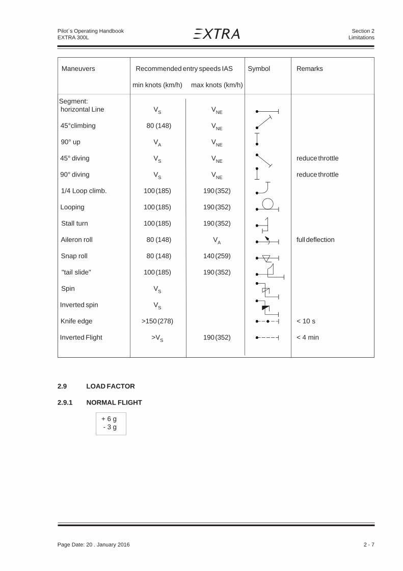
Maneuvers Recommended entry speeds IAS Symbol Remarks
min knots (km/h) max knots (km/h)
Segment: horizontal Line VS VNE
45°climbing 80 (148) VNE
90° up VA VNE
45° diving VS VNE reduce throttle
90° diving VS VNE reduce throttle
1/4 Loop climb. 100 (185) 190 (352)
Looping 100 (185) 190 (352)
Stall turn 100 (185) 190 (352)
Aileron roll 80 (148) VA full deflection
Snap roll 80 (148) 140 (259)
"tail slide" 100 (185) 190 (352)
Spin VS
Inverted spin VS
Knife edge >150 (278) < 10 s
Inverted Flight >VS 190 (352) < 4 min
2.9 LOAD FACTOR
2.9.1 NORMAL FLIGHT
+ 6 g - 3 g
Page Date: 20 . January 2016

2 - 8 Page Date: 20. April 2002
Pilot´s Operating HandbookEXTRA 300L
Section 2Limitations
2.9.2 ACROBATIC FLIGHT
+ 10 g / - 10 g for 1 seat occupied (MTOW 820 kg / 1808 lbs)+ 8 g / - 8 g for 2 seat occupied (MTOW 870 kg / 1918 lbs)
2.10 FLIGHT CREW LIMITS
Minimum crew is one pilot in the rear seat. Solo flying from rear seat only. Maximum2 persons are allowed. For hearing protection noise supression (passive or active)communication headsets are required. The rear cockpit is equipped with a complete set ofairplane controls and instruments.
2.11 KINDS OF OPERATIONAL LIMITS
Only VFR flights at day are allowed. The A/C may be operated at OAT from -20°C (-4°F) to+44°C (+111°F). Below temperatures of -10°C (+14°F) the oil vent line must be modified bythe low temperature kit (breather line). Flight in known icing-conditions is prohibited.Smoking is prohibited.
2.11.1 STRUCTURAL TEMPERATURE/COLOUR LIMITATION
Structure is qualified up to 72°C (161.6°F). Structure temperatures (composite) above 72°C(161.6°F) are not permitted. Not to exceed this temperature limit, color specification forcomposite structure (manufacturer document EA-03205.19) has to be complied with.
To check the temperature inside the cockpit (potential "green house" effect) a reversibletemperature indicator (STRUCTURAL OVERHEAT INDICATOR) is applied on the upperside of the wing main spar in the carry-through section. After reaching the temperature limitof 72°C (161,6°F) the word "RISK" appears and flying is prohibited.
2.12 MAXIMUM OPERATING ALTITUDE
Max. certified operating altitude is 16000 ft MSL (4877 m)
2.13 TIRE PRESSURE
The tire pressure is 3,4 Bar (49,3 PSI).
2.14 MARKINGS AND PLACARDS2.14.1 AIRCRAFT IDENTITY PLACARDS
or
EXTRAFLUGZEUGPRODUKTIONS-UND VERTRIEBS-GMBHMODEL: EA 300/LSERIAL NUMBER: _______
TC-NUMBER: A67EU
Page Date: 20. January 2016
RISK
CAUTION:While the word
RISKappears, flying is prohibited !
STRUCTURALOVERHEATINDICATOREXTRA
MANUFACTUREREXTRA FLUGZEUGBAU GMBHMODEL: EA 300/LSERIAL NUMBER: _______TC-NUMBER:

Page Date: 20. April 2002 2 - 9
Pilot´s Operating HandbookEXTRA 300L
Section 2Limitations
OFF
WINGTANK 120 L
USABLE(31,7 US
GAL)
ACRO & CENTER45.5 L USABLE (12.0 US GAL)
FUELSELECTOR
=>
2.14.2 OPERATING PLACARDS
or (near airspeed indicator)
THE MARKINGS AND PLACARDS INSTALLED IN (in the rear cockpit)THIS AIRPLANE CONTAIN OPERATING LIMITATIONSWHICH MUST BE COMPLIED WITH WHEN OPERATINGTHIS AIRPLANE IN THE ACROBATIC CATEGORY.OTHER LIMITATIONS WHICH MUST BE COMPLIEDWITH WHEN OPERATING THIS AIRPLANE IN THISCATEGORY OR IN THE NORMAL CATEGORY ARECONTAINED IN THE AIRPLANE FLIGHT MANUAL.APPLICABLE RPM LIMITATION MUST BE OBSERVED.
THIS AIRPLANE IS CERTIFICATED (on the rear instrument panel)FOR VFR, DAY OPERATION.OPERATION IN KNOWN ICINGCONDITIONS IS PROHIBITED.
F U E L (near each filler cap)AVGAS 100/100 LL
OIL( (on the separatehatch / upper cowling)
(in both cockpits near selector valve handle)
NOSE DOWN <= NEUTRAL=> NOSE UP (near the handle at the right sideTRIM in the rear cockpit)
WING TANK (on the rear instrument panel underMUST BE EMPTY FOR ACROBATICS fuel capacity indicator)
ACRO & CENTER TANKSHOWS "ZERO" IN LEVEL FLIGHT BELOW 11 L (2.9 US GAL)
UNUSABLE FUEL 5.5 L (1.5 US GAL.)
Page Date: 16. March 2009

2 - 10 Page Date: 20. April 2002
Pilot´s Operating HandbookEXTRA 300L
Section 2Limitations
THE REMAINING FUEL IN LEVEL FLIGHT (on the rear instrument panelCANNOT BE USED SAFELY under the acro & center tank fuelWHEN INDICATOR READS "ZERO". capacity indicator)
ACROBATIC: ± 10 G, 1 PILOT ± 8 G, 2 PERSON ON BOARDMTOW: 820 KG (1808 LBS) MTOW: 870 KG (1918 LBS)
NORMAL: + 6 G/ -3 G; MTOW: 950 KG (2095 LBS) (in both cockpits)ACROBATICS INCL. SPIN NOT APPROVED
AUXILIARY FUEL PUMP (near pump-switch on the instrument panel in the rear cockpit)
ON OFF
NO SMOKING (in both cockpits)
USE OF HEADSET IS REQUIRED (on the right side of bothUSE OF PARACHUTE IS RECOMMENDED instrument panels)
NO BAGGAGE (on Lexan® cover aft pilot's seat, if installed)
MAGNETIC (near Mag. Dir. Indicator)DIRECTION INDICATORCALIBRATION
LOW RPM <= PROP => HIGH RPM (on RPM control unit in the rear cockpit)
LEAN <= MIXTURE => RICH (on mixture control unit in the rear cockpit)
CLOSE <= THROTTLE => OPEN (near throttle control in both cockpits)
LOCK <= CANOPY => UNLOCK (near canopy locking handlesof each cockpit)
V E N T (near the eyeball-type adjustable vents)
O P E N
Page Date: 15. December 2005

Page Date: 20. April 2002 2 - 11
Pilot´s Operating HandbookEXTRA 300L
Section 2Limitations
or
(in both cockpits)
or
WARNING:SOLO FLYING FROM (on front instrument panel)REAR SEAT ONLY!
Maneuvers Airspeeds Maneuvers Airspeedsmin km/h max min max
Segment:
Horizontal Line V V Aileron roll 148 293
45°climbing 148 V Snap roll 148 259
90° up 293 V "Tail-slide" 185 352
45° diving V V Spin V ----
90° diving V V Inverted spin V ----
1/4 Loop climb. 185 352 Inverted flight > V 352(Less than 4 min)
Loop 185 352Knife edge >278 ----
Stall turn 185 352 (Less than 10 s)
S NE
NE
NE
S NE S
S NE S
S
km/h km/h km/h
Approved acrobatic maneuvers and recommended entry airspeeds
Page Date: 16. March 2009

2 - 12 Page Date: 20. April 2002
Pilot´s Operating HandbookEXTRA 300L
Section 2Limitations
2.14.3 INSTRUMENT MARKINGS
AIRSPEED INDICATOR
green arc 60 KIAS (111 km/h) - 158 KIAS (293 km/h)yellow arc 158 KIAS (293 km/h) - 220 KIAS (407 km/h)red line 220 KIAS (407 km/h)
OIL PRESSURE INDICATOR
Range markings are depending on instrument installed.
red line 25 Psiyellow arc 25 Psi - 55 Psigreen arc 55 Psi - 90 Psi or 55 Psi - 95 Psiyellow arc 90 Psi - 100 Psi or 95 Psi - 115 Psired line 100 Psi or 115 Psi
OIL TEMPERATURE INDICATOR
yellow arc < 140 °Fgreen arc 140 °F - 210 °Fyellow arc 210 °F - 245 °Fred line 245°F
CYLINDERHEAD TEMPERATURE INDICATOR
yellow arc < 150 °Fgreen arc 150 °F - 435 °Fyellow arc 435 °F - 500 °Fred line 500°F
RPM INDICATOR
green arc 700 RPM - 2400 RPMyellow arc* 2400 RPM - 2700 RPMred line 2700 RPM
G - METER
green arc - 5 g - + 8 gyellow arc + 8 g - + 10 gred line + 10 g
FUEL FLOW INDICATOR
green arc 0 gal / h - 35 gal / hred radial 35 gal / h
*) Refer to Section 4.6 and 4.8.2
Page Date: 19. April 2012

Page Date: 20. April 2002 2 - 13
Pilot´s Operating HandbookEXTRA 300L
Section 2Limitations
MANIFOLD PRESSURE INDICATOR
green arc 10 " Hg - 25 " Hgyellow arc 25 " Hg - 29.5 " Hgred radial 29.5 " Hg
2.15 KINDS OF OPERATION EQUIPMENT LIST
The aircraft may be operated in day VFR when the appropriate equipment is installed andoperable. Flying under icing conditions is prohibited.
The following equipment list identifies the systems and equipment upon which typecertification for each kind of operation was predicated. The following systems and items ofequipment must be installed and operable for the particular kind of operation indicated.
NORMAL ACROBATIC 1 seat 2 seats
COMMUNICATION
1. Transceiver-VHF 1 1 1
ELECTRICAL POWER
1. Battery 1 1 12. Alternator 1 1 13. Ammeter 1 1 1
FLIGHT CONTROL SYSTEM
1. Elevator-trim control 1 1 12. Stall warning 1 1 1
FUEL
1. Boost pump 1 1 12. Fuel quantity indicator 2 2 23. Manifold pressure 1 1 14. Fuel flow indicator 1 1 15. Fuel pressure 0 0 0
LIGHT
1. Wing-tip position / strobe light 1 1 1
NAVIGATION
1. Altimeter 1 1 12. Airspeed indicator 1 1 13. Mag. direction indicator 1 1 14. OAT indicator 0 0 05. Vertical speed indicator 0 0 06. Turn and bank indicator 0 0 07. Artificial horizon 0 0 08. Directional gyro 0 0 09. Transponder1 1 1 1
Page Date: 15. December 2005
1) In some airspaces Mode S Elementary Surveillance functionality is required

2 - 14 Page Date: 20. April 2002
Pilot´s Operating HandbookEXTRA 300L
Section 2Limitations
NORMAL ACROBATIC 1 seat 2 seats
ENGINE CONTROL
1. RPM indicator 1 1 12. Exhaust gas temperature ind. 0 0 03. Cylinder head temperature ind. 0 0 0
OIL
1. Oil temperature indicator 1 1 12. Oil pressure indicator 1 1 1
FLIGHT CREW EQUIPMENT
1. Parachute rear 0 * *2. Parachute front 0 0 *3. Seat belt rear 1 1 14. Seat belt front 1 0 15. Headset rear 1 1 16. Headset front 1 0 1
N O T E
The zeros ( 0 ) used in the above list mean that either the equipment or system, orboth were not required for type certification for that kind of operation.Either equipment or systems in addition to those listed above may be required by thenational operating regulations.
The asterisks ( * ) used in the above list mean that latest national aviation regulationsmust be observed in determining whether the equipment and/or system are required.
According FAR Part 91 „General Operating and Flight Rules" each occupant of an USregistered airplane must wear an approved parachute when performing acrobaticmaneuvers.
Extra Flugzeugproduktions- und Vertriebs- GmbH considers acrobatics withoutwearing an approved parachute to be unsafe.
Page Date: 20. January 2016

Page Date: 20. April 2002 3 - 1
Section 3Emergency Procedures
Pilot´s Operating HandbookEXTRA 300L
SECTION 3
EMERGENCY PROCEDURES
Table of Contents
Paragraph PageSECTION 3 EMERGENCY PROCEDURES
3.0 INTRODUCTION................................................................................................................. 3-33.0.1 General ............................................................................................................................... 3-33.0.2 General Behaviour in Emeregency Situations ..................................................................... 3-3
3.1 AIRSPEEDS FOR EMERGENCY OPERATION .................................................................. 3-4
3.2 OPERATIONAL CHECKLIST ............................................................................................. 3-43.2.1 Engine Failure during Take-off Roll ...................................................................................... 3-43.2.2 Engine Failure immediately after Take-off ............................................................................ 3-43.2.3 Engine Failure during Flight (Restart Process) .................................................................... 3-43.2.4 Oil System Malfunction ........................................................................................................ 3-53.2.5 Alternator Failure ................................................................................................................. 3-5
3.3 FORCED LANDINGS.......................................................................................................... 3-53.3.1 Emergency Landing without Engine Power ......................................................................... 3-53.3.2 Precautionary Landing with Engine Power........................................................................... 3-5
3.4 FIRES ................................................................................................................................. 3-63.4.1 During Start on Ground........................................................................................................ 3-63.4.2 If Engine Fails to Start ......................................................................................................... 3-63.4.3 Engine Fire in Flight............................................................................................................. 3-7
3.5 ICING .................................................................................................................................. 3-73.5.1 Inadvertent Icing Encounter ................................................................................................. 3-7
3.6 UNINTENTIONAL SPIN ...................................................................................................... 3-7
3.7 MANUAL BAIL-OUT ........................................................................................................... 3-7
3.8 EMERGENCY EXIT AFTER TURN OVER .......................................................................... 3-8
3.9 ELEVATOR CONTROL FAILURE ....................................................................................... 3-8

3 - 2 Page Date: 20. April 2002
Section 3Emergency Procedures
Pilot´s Operating HandbookEXTRA 300L
Left blank intentionally

Page Date: 20. April 2002 3 - 3
Section 3Emergency Procedures
Pilot´s Operating HandbookEXTRA 300L
SECTION 3
EMERGENCY PROCEDURES
3.0 INTRODUCTION
3.0.1 GENERAL
This section contains the checklist and procedures coping with emergencies that may occur.This checklist must be followed in various emergencies to ensure maximum safety for thecrew and/or aircraft.Thorough knowledge of these procedures will enable the aircrew to better cope with anemergency. The steps should be performed in the listed sequence. However the proceduresdo not restrict the aircrew from taking any additional action necessary to deal with theemergency.
3.0.2 GENERAL BEHAVIOUR IN EMEREGENCY SITUATIONS
As soon as one of the crew member becomes aware that an emergency situation exists, hemust immediately alert the other crew member of the situation. In any emergency situation,contact should be established with a ground station as soon as possible after completing theinitial corrective action. Include position, altitude, heading, speed, natureof the emergency and pilot's intentions in the first transmission. There after the groundstation should be kept informed of the progress of the flight and of any changes ordevelopments in the emergency. Three basic rules apply to most emergencies and shouldbe observed by each aircrew member:
1. Maintain aircraft control2. Analyze the situation and take proper action3. Land as soon as possible/as soon as practical
The meaning of "as soon as possible" and "as soon as practical" as used in this section isas follows:
Land AS SOON AS POSSIBLE (ASAP) = Emergency conditions are urgent and require animmediate landing at the nearest suitableairfield, considering also other factors, such asweather conditions and aircraft mass.
Land AS SOON AS PRACTICAL= Emergency conditions are less urgent and in theaircrews judgement the flight may be safelycontinued to an airfield where more adequatefacilities are available.
W A R N I N G
Make only one attempt to restore an automatically disconnected power source or reset or replacean automatically disconnected CPD (circuit protection device) that affects flight operations orsafety. Each successive attempt to restore an automatically disconnected power source, or theresetting of an automatically disconnected CPD can result in progressively worse effects.
Page Date: 20. January 2016

3 - 4 Page Date: 20. April 2002
Section 3Emergency Procedures
Pilot´s Operating HandbookEXTRA 300L
3.1 AIRSPEEDS FOR EMERGENCY OPERATION
Stall speed 60 KIAS (111 km/h)
Engine failure after take-off 80 KIAS (148 km/h)
Best recommended gliding speed ( glide angle 1 : 6,2 )
-Normal (950 kg) 90 KIAS (167 km/h)
-Acro (820 kg) 80 KIAS (148 km/h)
Precautionary landing with engine power 80 KIAS (148 km/h)
Landing without engine power 80 KIAS (148 km/h)
Maximum demonstrated cross windcomponent 15 Knots (27 km/h)
3.2 OPERATIONAL CHECKLIST
3.2.1 ENGINE FAILURE DURING TAKE-OFF ROLL
1. Throttle IDLE2. Brakes APPLY3. Mixture IDLE CUT OFF4. Ignition switch OFF5. Master switch OFF
3.2.2 ENGINE FAILURE IMMEDIATELY AFTER TAKE-OFF
Stall speed 60 KIAS (111 km/h)
1. Airspeed 80 KIAS (148 km/h)2. Mixture IDLE CUT OFF3. Fuel shutoff valve OFF (Pull & Turn)4. Ignition switch OFF5. Master switch OFF6. Forced landing PERFORM as practical
3.2.3 ENGINE FAILURE DURING FLIGHT (RESTART PROCESS)
1. Airspeed 80 KIAS (148 km/h)2. Fuel shutoff valve CENTER & ACRO3. Mixture RICH4. Boost pump ON5. Ignition switch BOTH
(or START if propeller has stopped)
Page Date: 16. March 2009

Page Date: 20. April 2002 3 - 5
Section 3Emergency Procedures
Pilot´s Operating HandbookEXTRA 300L
3.2.4 OIL SYSTEM MALFUNCTION
If oil pressure indicates low: Apply positive "g"If oil pressure is not regained then:1. Airspeed 80 KIAS (148 km/h)2. Throttle REDUCE TO IDLE3. Engine oil temperature OBSERVE INDICATION4. Land ASAP
N O T E
If oil pressure drops to 0 psi (kPa) the propeller pitch changes automatically to coarse(high) pitch with a corresponding decrease in RPM.
3.2.5 ALTERNATOR FAILURE
An alternator failure is indicated by the red light of the low voltage monitor.If red light illuminates:
1. Alternator SWITCH OFF AND ON2. Low voltage monitor CHECK INDICATION3. Red light off CONTINUE FLIGHT
If red light illuminates again:4. Land AS SOON AS PRACTICAL
3.3 FORCED LANDINGS
3.3.1 EMERGENCY LANDING WITHOUT ENGINE POWER
1. Seat belts, shoulder harnesses SECURE2. Airspeed 80 KIAS (148 km/h)3. Mixture IDLE CUT OFF4. Fuel shutoff valve OFF (Pull & Turn)5. Ignition switch OFF6. Master switch OFF7. Touchdown SLIGHTLY TAIL LOW8. Brakes OPTIMUM BRAKING
3.3.2 PRECAUTIONARY LANDING WITH ENGINE POWER
1. Seat belts, shoulder harnesses SECURE2. Airspeed 80 KIAS (148 km/h)3. Selected field FLY OVER,
noting terrain and obstructions, thenreaching a safe altitude and airspeed
4. Master switch OFF5. Touchdown SLIGHTLY TAIL LOW6. Ignition switch OFF7. Mixture IDLE CUT OFF8. Fuel shutoff valve OFF (Pull & Turn)9. Brakes APPLY HEAVILY
Page Date: 16. March 2009Page Date: 20. January 2016

3 - 6 Page Date: 20. April 2002
Section 3Emergency Procedures
Pilot´s Operating HandbookEXTRA 300L
WARNING
3.4 FIRES
3.4.1 DURING START ON GROUND
1. Cranking CONTINUE to get a startwhich would suck theflames and accumulatedfuel through the airinlet and into the engine.
2. Fuel shutoff valve OFF (Pull & Turn)
3. Power 1700 RPM for one minute.
4. Engine SHUT DOWN
5. After engine stop ABANDON aircraft andinspect for damage
6. Fire EXTINGUISH using fireextinguisher if available
W A R N I N G
Risk of burns due to flames shooting out.Do not open engine compartment access doors while engine is on fire.
3.4.2 IF ENGINE FAILS TO START
1. Cranking CONTINUE2. Throttle FULL OPEN3. Mixture IDLE CUT OFF4. Fuel shutoff valve OFF (Pull & Turn)
If fire is extinguished
5. Master switch OFF6. Ignition switch OFF7. Engine compartment INSPECT
Page Date: 20. January 2016

Page Date: 20. April 2002 3 - 7
Section 3Emergency Procedures
Pilot´s Operating HandbookEXTRA 300L
3.4.3 ENGINE FIRE IN FLIGHT
1. Mixture IDLE CUT OFF2. Fuel shutoff valve OFF (Pull & Turn)3. Master switch OFF4. Airspeed 100 KIAS (185 km/h),
find your airspeed/attitudewhich will keep the fire awayfrom the cockpit
5. Land as soon as possible
3.5 ICING
3.5.1 INADVERTENT ICING ENCOUNTER
1. Turn back or change altitude to obtain an outside temperature that is lessconductive to icing.
2. Plan a landing at the nearest airfield. With extremely rapid ice build-up select asuitable "off airport" landing field.
3.6 UNINTENTIONAL SPIN
Refer to section 4 (Normal Procedures) acrobatic maneuver, spin recovery.
3.7 MANUAL BAIL-OUT
When in an emergency situation that requires abandoning the aircraft and while wearing aparachute, which is at least strongly recommended for acrobatics:
1. Inform your passenger2. Reduce speed to 100 KIAS (185 km/h) if possible3. Pull mixture to lean4. Open canopy (the low pressure over the canopy in normal flight
will flip the canopy full open immediately)5. Take off headset6. Open seat belt7. Leave airplane to the left side8. Try to avoid wing and tail9. Open parachute
Page Date: 16. March 2009
3 - 8 Page Date: 20. April 2002
Section 3Emergency Procedures
Pilot´s Operating HandbookEXTRA 300L
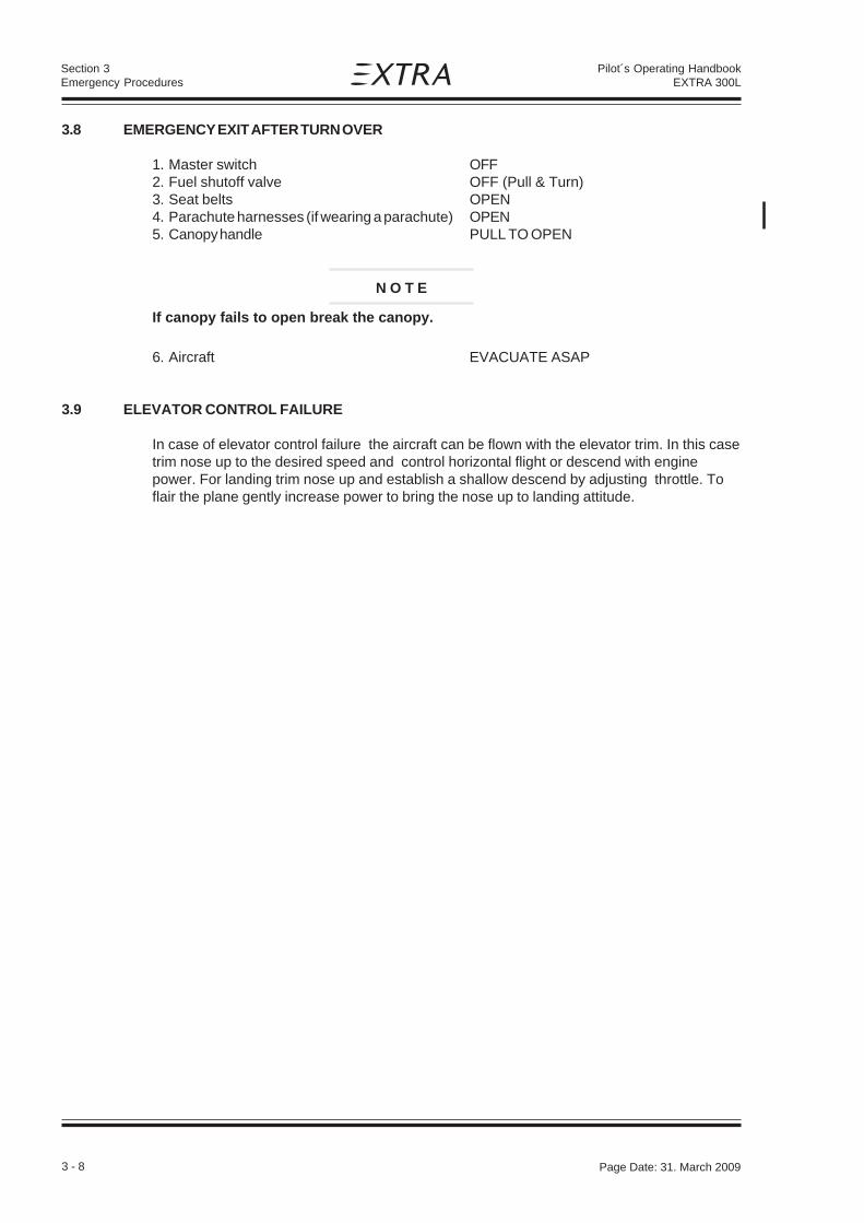
3.8 EMERGENCY EXIT AFTER TURN OVER
1. Master switch OFF2. Fuel shutoff valve OFF (Pull & Turn)3. Seat belts OPEN4. Parachute harnesses (if wearing a parachute) OPEN5. Canopy handle PULL TO OPEN
N O T E
If canopy fails to open break the canopy.
6. Aircraft EVACUATE ASAP
3.9 ELEVATOR CONTROL FAILURE
In case of elevator control failure the aircraft can be flown with the elevator trim. In this casetrim nose up to the desired speed and control horizontal flight or descend with enginepower. For landing trim nose up and establish a shallow descend by adjusting throttle. Toflair the plane gently increase power to bring the nose up to landing attitude.
Page Date: 31. March 2009

Page Date: 20. April 2002 4 - 1
Section 4Normal Procedures
Pilot´s Operating HandbookEXTRA 300L
SECTION 4
NORMAL PROCEDURES
Table of Contents
Paragraph PageSECTION 4
4.0 GENERAL............................................................................................................................ 4-34.0.1 Airspeeds for Normal Operation ........................................................................................... 4-34.0.2 Checklist and Procedures .................................................................................................... 4-3
4.1 PREFLIGHT INSPECTION .................................................................................................. 4-44.1.1 Exterior Inspection Illustration .............................................................................................. 4-44.1.2 General ................................................................................................................................ 4-4
4.2 CHECKLIST PROCEDURES ............................................................................................... 4-4
4.3 STARTING PROCEDURES.................................................................................................. 4-64.3.1 Cold Engines ....................................................................................................................... 4-64.3.2 Hot Engines ......................................................................................................................... 4-6
4.4 TAXIING THE AIRCRAFT .................................................................................................... 4-6
4.5 TAKE-OFF PROCEDURE..................................................................................................... 4-74.5.1 Before Take-Off .................................................................................................................... 4-74.5.2 Take-Off ............................................................................................................................... 4-7
4.6 CLIMB ................................................................................................................................. 4-7
4.7 CRUISE ............................................................................................................................... 4-7
4.8 LANDING PROCEDURES ................................................................................................... 4-84.8.1 Descent ............................................................................................................................... 4-84.8.2 Approach ............................................................................................................................. 4-84.8.3 Before Landing ..................................................................................................................... 4-84.8.4 Normal Landing .................................................................................................................... 4-8
4.9 GO-AROUND ....................................................................................................................... 4-9
4.10 SHUTDOWN........................................................................................................................ 4-9
4.11 LEAVING THE AIRCRAFT ................................................................................................... 4-9
4.12 ACROBATIC MANEUVERS ...............................................................................................4-104.12.1 General ...............................................................................................................................4-104.12.2 Maneuvers ..........................................................................................................................4-104.12.3 Spin ....................................................................................................................................4-12
4.13 NOISE LEVEL ....................................................................................................................4-12
Page Date: 20. January 2016

4 - 2 Page Date: 20. April 2002
Section 4Normal Procedures
Pilot´s Operating HandbookEXTRA 300L
Left blank intentionally

Page Date: 20. April 2002 4 - 3
Section 4Normal Procedures
Pilot´s Operating HandbookEXTRA 300L
SECTION 4
NORMAL PROCEDURES
4.0 GENERAL
4.0.1 AIRSPEEDS FOR NORMAL OPERATION
CATEGORY ACRO NORMAL1 seat 2 seats
KIAS (km/h) KIAS (km/h) KIAS (km/h)
Start:
-Rotate Speed 60 (111) 62 (115) 65 (120)
Climb:
-Vx 87 (161) 89 (165) 93 (172)
-Vy 96 (178) 99 (183) 104 (193)
-Recommended NormalClimb Speed 100 (185) 105 (194) 110 (204)
-Max. Cruise 185 (343) 185 (343) 185 (343)
Landing:
-Approach 80 (148) 85 (157) 90 (167)
-on Final 72 (133) 74 (137) 78 (144)
-Go-Around Speed 90 (167) 95 (176) 100 (185)
Recommended AirspeedFor Flight In Rough Air (max.) (VA) 158 (293) 158 (293) 140 (259)
Max. Demonstrated CrossWind Component 15 kts (27) 15 kts (27) 15 kts (27)
4.0.2 CHECKLIST AND PROCEDURES
This handbook contains the checklist and procedures to operate the aircraft in normal andacrobatic operation. The pilot should be familiar with all procedures contained in this Pilot'sOperating Handbook, which must be carried on board. The pilot has to comply with thechecklist for daily check and inspections (see Section 8, Handling, Servicing andMaintenance).
Page Date: 19. April 2012

4 - 4 Page Date: 20. April 2002
Section 4Normal Procedures
Pilot´s Operating HandbookEXTRA 300L
4.1 PREFLIGHT INSPECTION
4.1.1 EXTERIOR INSPECTION ILLUSTRATION
4.1.2 GENERAL
Visually check airplane for general condition during walk around inspection. Perform exteriorcheck as outlined in the picture above in counterclockwise direction.
4.2 CHECKLIST PROCEDURES
1) Cockpit
1. Pilot's Operating Handbook (AVAILABLE)2. Airplane weight and balance CHECKED3. Ignition switch OFF4. Master switch ON5. Fuel quantity indicators CHECK6. Master switch OFF7. Fuel selector * ACRO & CENTER TANK
N O T E*
Although safe operation does not require the use of the tanks in a specific sequence,it is recommended to set fuel selector to "ACRO & CENTER TANK" position!
2) Empennage
1. All round inspection, canopy, surfaces,stabilizers, elevator, trim tab, rudder and tailwheel CHECK
2. Horizontal stabilizer attachment bols CHECK FOR FREEPLAY BYMOVING THE TIP OF THEHORIZ. STABILIZER UP- ANDDOWNWARDS
3) Right Wing
1. Aileron, freedom of movement and security CHECK2. Trailing edge CHECK3. Fuel tank vent opening (right landing gear) CHECK4. Fuel quantity CHECK5. Fuel tank filler cap CHECK6. Right landing gear, wheel and brake CHECK7. Stall warning vane CHECK
3
21
5
4
Page Date: 19. April 2012

Page Date: 20. April 2002 4 - 5
Section 4Normal Procedures
Pilot´s Operating HandbookEXTRA 300L
4) Nose
1. Engine oil dipstick CHECK2. Propeller and spinner CHECK3. Air inlet CHECK4. Acro & center fuel tank drain DRAIN FOR AT LEAST
4 SECONDS TO CLEAR SUMP OFPOSSIBLE WATER;CHECK CLOSED
5. Wing fuel tank drain DRAIN FOR AT LEAST4 SECONDS TO CLEAR SUMP OFPOSSIBLE WATER;CHECK CLOSED
6. Fuel filter drain DRAIN FOR AT LEAST4 SECONDS TO CLEAR FILTEROF POSSIBLE WATER;CHECK CLOSED
7. Exhaust silencer (if installed) CHECK FOR DAMAGE ANDSECURE ATTACHMENT
5) Left wing
1. Left landing gear, wheel and brakes CHECK2. Fuel quantity CHECK3. Fuel tank filler cap CHECK4. Pitot cover REMOVE5. Trailing edge CHECK6. Aileron, freedom of movement and security CHECK
6) Before starting engine
1. Preflight inspection COMPLETE2. Passenger briefing COMPLETE3. Parachute handling briefing COMPLETE4. Seats, seatbelts, shoulder harnesses ADJUST AND LOCK5. Canopy CLOSE AND LOCK6. Brake CHECK7. Master switch ON8. Avionics power switch OFF9. Electrical equipment OFF10.Alternator ON11.Wingtip position / Strobe lights ON

4 - 6 Page Date: 20. April 2002
Section 4Normal Procedures
Pilot´s Operating HandbookEXTRA 300L
4.3 STARTING PROCEDURES
4.3.1 COLD ENGINES
The following starting procedures are recommended, however, the starting conditions maynecessitate some variation from these procedures.
1. Perform pre-flight inspection.
2. Set propeller governor control to "High RPM" position.
3. Open throttle approximately 1/4 travel.
4. Turn boost pump "ON".
5. Move mixture control to "FULL RICH" until a slight but steadyfuel flow is noted (approximately 3 to 5 seconds) and returnmixture control to "IDLE CUT-OFF".Turn bost pump "OFF".
6. Engage starter.
7. When engine fires release the ignition switch back to "BOTH".
8. Move mixture control slowly and smoothly to "FULL RICH".
9. Check the oil pressure gauge. If minimum oil pressure is notindicated within 30 seconds, shut off the engine and determine trouble.
4.3.2 HOT ENGINES
Because of the fact that the fuel percolates and the system must be cleared of vapor, it isrecommended to use the same procedure as outlined for cold engine start.
4.4 TAXIING THE AIRCRAFT
1. Canopy CLOSE AND LOCK2. Brake CHECK3. Altimeter Set on QFE or QNH
Scale error max. +60 ft4. Avionic master switch ON5. Electrical equipment ON6. Radio Set and test7. Mixture Leave in "FULL RICH" position
Operate only with the propeller in minimum blade angle (High RPM).Warm-up at approximately 1000-1200 RPM. The engine is ready for take-off when thethrottle can be opened without the engine faltering.

Page Date: 20. April 2002 4 - 7
Section 4Normal Procedures
Pilot´s Operating HandbookEXTRA 300L
4.5 TAKE-OFF PROCEDURE
4.5.1 BEFORE TAKE-OFF
Before you line up at the runway for take-off:
- Check oil pressure and oil temperature.
N O T E
The RPM Gauge is electronically operated. To check the magnetos the RPM sourceswitch must be set to the same magento as the igintion switch. Otherwise the gaugewill show zero.
- Check the magnetos at 1800 RPM. Allowed drop is 175 RPM(max. difference 50 RPM).
- Check Alternator Output.
- Move also the propeller control through its complete range to check operation andreturn to full "HIGH RPM" position.
- Turn boost pump "ON" (check indicator movement on the fuel flow gauge).
- Check flight control free and correct
- Set trim to appropriate takeoff position (half way nose down)
4.5.2 TAKE-OFF
Set throttle smoothly to max and let the airspeed go up to 60-65 KIAS (111-120 km/h). A lightpressure on the stick lifts the tail to horizontal position. Rotate the aircraft at 65 KIAS(120 km/h). On reaching climb speed of 100 KIAS (185 km/h) proceed with climb.
4.6 CLIMB
Climbs may be performed up to 2700 RPM. RPM above 2400 should, however, be used onlywhen necessary for maximum performance in order to avoid unnecessary noise.
Turn boost pump "OFF".
4.7 CRUISE
1. Altitude - As selected2. Throttle / RPM - Adjust for cruising speed3. Mixture - Adjust for minimum fuel consumption4. Trim - As required5. Fuel - Check periodically
Page Date: 20. January 2016

4 - 8 Page Date: 20. April 2002
Section 4Normal Procedures
Pilot´s Operating HandbookEXTRA 300L
4.8 LANDING PROCEDURES
4.8.1 DESCENT
1. Throttle - Reduce2. Mixture - "FULL RICH"3. RPM Control - Set to 2400 RPM4. Trim - Adjust5. Fuel selector* - "ACRO & CENTER TANK"
N O T E*
Although safe operation does not require the use of the tanks in a specific sequence,it is recommended to set fuel selector to "ACRO & CENTER TANK" position!
4.8.2 APPROACH
1. Boost pump - ON2. Mixture - set to "RICH"3. Airspeed - reduce to approach speed4. Propeller - set to low pitch ("HIGH RPM")
N O T E
It is recommended to set the RPM to 2400 during approach and landing in order toavoid unnecessary noise.
In case of "Go Around", RPM control must be set to max. RPM before applying po-wer.
4.8.3 BEFORE LANDING
1. Landing approach - proceed2. Airspeed on final - maintain 78 KIAS (144 km/h)3. Elevator trim - adjust
N O T E
Stall speed will be:
MTOW = 820 kg: 55 KIAS (102 km/h)MTOW = 870 kg: 57 KIAS (106 km/h)MTOW = 950 kg: 60 KIAS (111 km/h)
4.8.4 NORMAL LANDING
1. Landing - perform as practicable with respect to surface and weather condition
2. Touchdown - 3 point landing
Page Date: 31. March 2009

Page Date: 20. April 2002 4 - 9
Section 4Normal Procedures
Pilot´s Operating HandbookEXTRA 300L
N O T E
The rudder is effective down to 30 KIAS (56 km/h)
3. Throttle - CLOSE / IDLE
4. Braking - Minimum required
4.9 GO-AROUND
Decide early in the approach if it is necessary to go around andthen start go-around before too low altitude and airspeed arereached.
Proceed as follows:
1. RPM control - "HIGH RPM" / Full forward2. Throttle - "OPEN" / Take-off power3. Airspeed - Minimum 90 KIAS (167 km/h)
rotate to go-around altitude
4.10 SHUTDOWN
1. Boost pump - "OFF"2. Engine - Run for 1 min. at 1000 RPM3. Dead cut check - Perform4. Avionic master switch - "OFF" (if installed)5. Mixture - "IDLE CUT OFF"6. Ignition switch - "OFF"7. Master switch - "OFF"
4.11 LEAVING THE AIRCRAFT
1. Canopy - Close and lock2. Aircraft - Secure3. Pitot cover - Attach4. Log book - Complete
Page Date: 16. March 2009

4 - 10 Page Date: 20. April 2002
Section 4Normal Procedures
Pilot´s Operating HandbookEXTRA 300L
4.12 ACROBATIC MANEUVERS
4.12.1 GENERAL
N O T E
Prior to executing these maneuvers tighten harnesses and check all loose items are stowed.Start the maneuvers at safe altitude and maximum continuous power setting if not otherwisenoted.
For maneuver limits refer to Section 2 LIMITATIONS.
After termination of acrobatic maneuvers the artificial horizon (if installed) must be reset ifpossible.
At high negative g-loads and zero g-periods it is normal that oil pressure and RPMindication might drop down momentarily returning to normal status at positive g-loads.
W A R N I N G
The high permissible load factors of the airplane may exceed the individual physiologicallimits of pilot or passenger. This fact must be considered when pulling or pushing highg's.
4.12.2 MANEUVERS
W A R N I N G
Particular caution must be exercised when performing maneuvers at speeds aboveV
A [158 KIAS (293 km/h)]. Large or abrupt control inputs above this speed may impose
unacceptably high loads which exceed the structural capability of the aircraft.
Acrobatics is traditionally understood as maneuvers like loop, humpty bump, hammerheadturn, aileron roll etc..
This manual does not undertake to teach acrobatics, however, it is meant to demonstratethe plane's capabilities.
For this reason maneuvers are divided into segments. The segments are described.Limitations are pointed out.
- Segment horizontal line:A horizontal line may be flown with any speed between VS and VNE
Page Date: 20. January 2016

Page Date: 20. April 2002 4 - 11
Section 4Normal Procedures
Pilot´s Operating HandbookEXTRA 300L
- Segment line 45° climbing:The plane will follow the line at max. power. The speed will not decrease below 80 KIAS(148 km/h)
- Segment line 90° up:Any entry speed may be used. Out of a horizontal pull-up at 200 KIAS (370 km/h) thevertical penetration will be 2.500 ft. The speed will gradually decrease to 0.
N O T I C E
In extremely long lines a RPM decay may occur. This is related to a loss of oilpressure.Positive g´s should be pulled immediately in order to protect the engine. Oil pressurewill return immediately.
- Segment line 45° diving:Throttle must be reduced in order to avoid exceeding VNE.
- Segment lin 90° diving:Throttle must be reduced to idle in order to avoid exceeding VNE.
Above segments may be filled up with aileron rolls on snap rolls. Watch VA = 158 KIAS(293 km/h) for aileron rolls with max. deflection.Snap rolls should not be performed at speeds above 140 KIAS (259 km/h).
- Segment 1/4 loop, climbing:The minimum recommended speed is 100 KIAS (185 km/h). If the maneuver is to befollowed by a vertical line, a higher entry speed is required depending on the expectedlength of the line. A complete loop can be performed at speeds above 100 KIAS(185 km/h).
N O T E
Since the maximum horizontal speed is 185 KIAS (343 km/h), higher speeds shouldbe avoided in acrobatics since an unnecessary loss of altitude would occur.
- Torque maneuvers:All maneuvers with high angular velocity associated with high propeller RPM must beconsidered dangerous for the engine crankshaft.
Although wooden composite propeller blades are used, the gyroscopic forces at the propflange are extremely high.
N O T E
If performing a gyroscopic maneuver such as flat spin, power on, or knife edge spin,reduce RPM to 2400 in order to minimize the gyroscopic forces.
Page Date: 20. January 2016

4 - 12 Page Date: 20. April 2002
Section 4Normal Procedures
Pilot´s Operating HandbookEXTRA 300L
4.12.3 SPIN
To enter a spin proceed as follows:
- Reduce speed, power idle- When the plane stalls:- Kick rudder to desired spin direction- Hold ailerons neutral- Stick back (positive spinning), Stick forward (negative spinning)
The plane will immediately enter a stable spin.
- Ailerons against spin direction will make the spin flatter.- Ailerons into spin direction will lead to a spiral dive.
Above apply for positive and negative spinning.
To stop the spin:
- Apply opposite rudder- Make sure, power idle- Hold ailerons neutral- Stick to neutral position
The plane will recover within 1/2 turn.Recovery can still be improved by feeding in in-spin ailerons.
N O T E
If ever disorientation should occur during spins (normal or inverted) one methodalways works to stop the spin:
- Power idle- Kick rudder to the heavier side
(this will always be against spin direction)- Take hands off the stick
The spin will end after 1/2 turn. The plane will be in a steep dive in a side-slip.Recovery to normal flight can be performed easily.
N O T E
After six turns of spinning the altitude loss including recovery is 2000 ft.
4.13 NOISE LEVEL
The noise level with silencer Gomolzig 606000 (6 in 1) and propeller MTV-14-B-C/C190-17 hasbeen established in accordance with ICAO Annex 16, as 77.3 dB(A)
The noise level with propeller MTV-9-B-C/C200-15 has been established in accordance withFAR 36 Appendix G, as 73.0 dB(A).
No determination has been made by the EASA for the FAA that the noise levels of this airplaneare or should be acceptable or unacceptable for operation at, into, or out any airport.
Page Date: 20. January 2016

Page Date: 20. April 2002 5 - 1
Section 5Performance
Pilot´s Operating HandbookEXTRA 300L
SECTION 5
PERFORMANCE
Table of Contents
Paragraph PageSECTION 5 PERFORMANCE
5.1 GENERAL ........................................................................................................................... 5-35.1.1 Performance Charts ............................................................................................................ 5-35.1.2 Definitions of Terms ............................................................................................................. 5-35.1.3 Sample Problem.................................................................................................................. 5-3
5.2 ISA CONVERSION.............................................................................................................. 5-5
5.3 AIRSPEED CALIBRATION ................................................................................................. 5-6
5.4 STALL SPEED .................................................................................................................... 5-7
5.5 TAKE-OFF PERFORMANCE .............................................................................................. 5-8
5.6 RATE OF CLIMB PERFORMANCE .................................................................................... 5-9
5.7 TIME TO CLIMB, FUEL TO CLIMB .................................................................................. 5-10
5.8 RANGE AND ENDURANCE ............................................................................................. 5-11
5.9 FUEL CONSUMPTION ..................................................................................................... 5-12
5.10 CRUISE PERFORMANCE ................................................................................................ 5-13
5.11 LANDING PERFORMANCE ............................................................................................. 5-14

5 - 2 Page Date: 20. April 2002
Pilot´s Operating HandbookEXTRA 300L
Section 5Performance
Left blank intentionally

Page Date: 20. April 2002 5 - 3
Section 5Performance
Pilot´s Operating HandbookEXTRA 300L
SECTION 5
PERFORMANCE
5.1 GENERAL
Performance data charts on the following pages are presented to facilitate the planning offlights in detail and with reasonable accuracy under various conditions. The data in thecharts have been computed from actual flight tests with the aircraft and engine in goodcondition and using average piloting techniques.
It should be noted that the performance information presented in the range and endurancecharts allow for 45 minutes reserve fuel at specified speeds. Some indeterminate variablessuch as engine and propeller, air turbulence and others may account for variations as highas 10% or more in range and endurance. Therefore, it is important to utilize all availableinformation to estimate the fuel required for the particular flight.
5.1.1 Performance Charts
Performance data are presented in tabular or graphical form to illustrate the effect of diffe-rent variables. Sufficiently detailed information are provided in the tables so thatconservative values can be selected and used to determine the particular performancefigure with reasonable accuracy.
All speeds in this chapter are Indicated Air Speeds (IAS) except otherwise stated. Theperformance figures below are given under following conditions.
1. Maximum allowed weight 950 kg (2095 lbs) except otherwise stated2. Take-off and landing on concrete surface.3. No wind.4. Standard atmospheric condition.
5.1.2 Definitions of Terms
For definition of terms, abbreviations and symbols refer to section 1, General.
5.1.3 Sample Problem
TAKE-OFF CONDITIONS
Field Pressure Alt 2000 ft (610 m)Temperature 15°C (59°F)Wind Component (Headwind) 8 KT (15 km/h)Field Length 3000 ft (914 m)
CRUISE CONDITIONS
Total Distance 400 NM (741 km)Pressure Altitude 8000 ft (2438 m)Temperature (ISA) -1°C (30°F)
Page Date: 16. March 2009

5 - 4 Page Date: 20. April 2002
Pilot´s Operating HandbookEXTRA 300L
Section 5Performance
TAKE-OFF
Take-Off Distance is shown by Fig. 5.5Example:
-T/O Weight: 870 kg (1918 lbs)-Ground Roll: 112 m (367 ft)-Total Distance to clear a 50 ft obstacle: 248 m (813 ft)
These distances are well within the available field length incl. the 8 kts (15 km/h) headwind.
RATE OF CLIMB
Fig. 5.6 shows the Rate Of Climb using Take-off PowerThe Rate of Climb at 2000 ft (610 m): 2320 ft/min (11.8 m/s)The Time to Climb from 2000 ft (610 m) to 8000 ft (2438 m) is acc. to Fig. 5.7:
=> (4,0 - 0,9) min = 3,1 minThe Fuel to Climb from 2000 ft (610 m) to 8000 ft (2438 m) is:
=> (5,8 - 1,4) Liters = 4,4 Liters (1.2 US Gal.)
CRUISE
Cruise Altitude and Power Setting should be determined for most economical fuelconsumption and several other considerations. In an altitude of 8000 ft (2438 m) and a PowerSetting of 65 % a Fuel Consumption of 52 L/H (13.7 US Gal/H) and 3,25 NM/L (12.3 NM/USGal) can be obtained by Fig. 5.9.
RANGE AND ENDURANCE
Fig. 5.8 presents Range and Endurance values for a T/O Weight of 950 kg (2095 lbs)including fuel for warm up and Take-Off from SL, max continuous Power climb to cruisingaltitude, and a reserve of 21 liter (5.5 US Gal.) for 45 minutes with 45% Power. 5,5 liters(1,45 US Gal.) unusable fuel is taken into account.
For the sample problem (appr.)
Total Fuel 171 L (45.1 US Gal.)Warm Up & T/O - 5 L (1.3 US Gal.)Reserve - 21 L (5.54 US Gal.)Unusable Fuel - 5.5 L (1.45 US Gal.)
====== ============Usable Fuel 139.5 L (36.8 US Gal.)
Range 415 NM (768 km)Endurance 2.49 HRS
Page Date: 16. March 2009

Page Date: 20. April 2002 5 - 5
Section 5Performance
Pilot´s Operating HandbookEXTRA 300L
5.2 ISA CONVERSION
ISA Conversion of pressure altitude and outside air temperature

5 - 6 Page Date: 20. April 2002
Pilot´s Operating HandbookEXTRA 300L
Section 5Performance
5.3 AIRSPEED CALIBRATION
N O T E
Indicated airspeed assumes zero instrument error
Page Date: 16. March 2009

Page Date: 20. April 2002 5 - 7
Section 5Performance
Pilot´s Operating HandbookEXTRA 300L
5.4 STALL SPEED
CONDITION:
POWER IDLEFORWARD C/G STALL SPEEDS
ANGLE OF BANK
WEIGHT CATEGORY 0° 30° 45°1g 1,15 g 1,41 g
kg (lbs) KIAS (km/h) KIAS (km/h) KIAS (km/h)
950 Normal 60 65 72(2095) (111) (120) (133)
870 ACRO (2 seat) 57 61 68(1918) (106) (113) (126)
820 ACRO (1 seat) 55 59 65(1808) (102) (109) (120)
Max altitude loss during stall recovery is approximately 100 ft (30 m)
Page Date: 16. March 2009

5 - 8 Page Date: 20. April 2002
Pilot´s Operating HandbookEXTRA 300L
Section 5Performance
5.5 TAKE-OFF PERFORMANCE
Power : T/O PowerRunway: Concrete
N O T E
For every 5 kts (9 km/h) headwind, the T/O distance can be decreased by 4%.For every 3 kts (6 km/h) tailwind [up to 10 kts (19 km/h)], the T/O distance is increasedby 10%.On a solid, dry and plain grass runway, the T/O is increased by 15%.
OAT 0°C (32°F) 15°C (59°F) 30°C (86°F)
T/O Rotating PA T/O T/O T/O T/O T/O T/Oweight Speed Roll over Roll over Roll over
15 m (50 ft) 15 m (50 ft) 15 m (50 ft)
kg KIAS ft (m) m (ft) m (ft) m (ft) m (ft) m (ft) m (ft) (lbs) (km/h)
950 65 SL 96 (315) 207 (679) 115 (377) 248 (813) 133 (436) 285 (935)(2095) (120) 2000 (610) 115 (377) 248 (814) 138 (453) 298 (978) 160 (525) 342 (1122)
4000 (1219) 138 (453) 298 (978) 166 (545) 357 (1171) 192 (630) 410 (1345)6000 (1829) 166 (545) 358 (1175) 199 (653) 429 (1407) 230 (755) 492 (1614)
870 62 SL 78 (256) 167 (548) 93 (305) 200 (656) 107 (351) 230 (755)(1918) (115) 2000 (610) 94 (308) 200 (656) 112 (367) 240 (787) 128 (420) 276 (906)
4000 (1219) 112 (367) 241 (791) 134 (440) 288 (945) 154 (505) 331 (1086)6000 (1829) 135 (443) 289 (948) 161 (528) 346 (1135) 185 (607) 397 (1302)
820 60 SL 67 (220) 114 (374) 79 (259) 170 (558) 93 (305) 200 (656)(1808) (111) 2000 (610) 80 (262) 173 (568) 95 (312) 204 (669) 112 (367) 240 (787)
4000 (1219) 97 (318) 207 (679) 114 (374) 248 (814) 134 (440) 288 (945)6000 (1829) 116 (381) 249 (817) 137 (449) 294 (965) 161 (528) 347 (1138)
Page Date: 16. March 2009
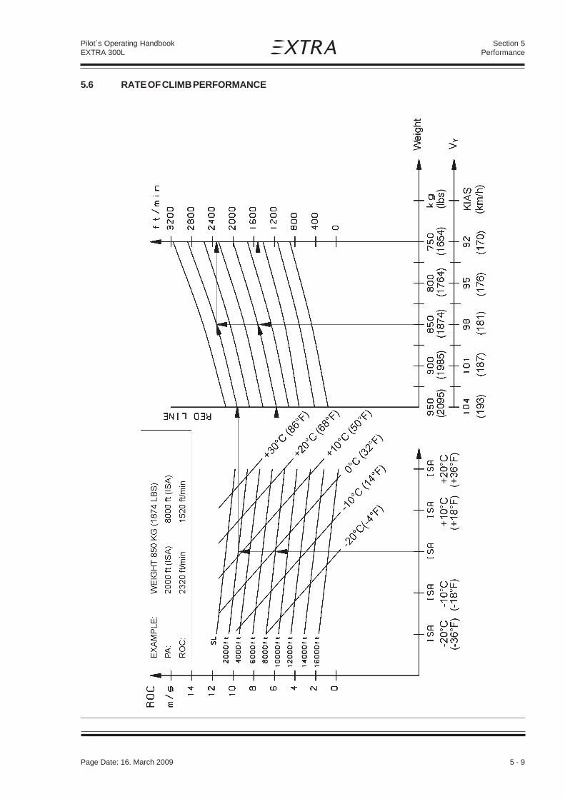
Page Date: 20. April 2002 5 - 9
Section 5Performance
Pilot´s Operating HandbookEXTRA 300L
5.6 RATE OF CLIMB PERFORMANCE
Page Date: 16. March 2009

5 - 10 Page Date: 20. April 2002
Pilot´s Operating HandbookEXTRA 300L
Section 5Performance
5.7 TIME TO CLIMB, FUEL TO CLIMB
EX
AM
PL
E
WE
IGH
T:
850
KG
(18
74 L
BS
)
AL
T:
2000
ft
(IS
A)
=>
800
0 ft
(IS
A)
TIM
E T
O C
LIM
B:
3.1
min
FU
EL
TO
CL
IMB
:4.
4 lt
r (1
.16
US
Gal
.)
WE
IGH
T /
KG
(LB
S)
2095
lbs
1654
lbs18
74 lb
s2029
lbs
1544
1654
1764
1874
1985
2095
LT
R
(US
GA
L.)
0.5
31.
592.
643.
704.
765.
81
FU
EL
TO
CL
IMB
CO
ND
ITIO
NS
:
MA
X. C
ON
T. P
OW
ER
CLI
MB
AT
VY
SP
EE
D; I
SA

Page Date: 20. April 2002 5 - 11
Section 5Performance
Pilot´s Operating HandbookEXTRA 300L
5.8 RANGE AND ENDURANCE
CO
ND
ITIO
N:
T/O
WE
IGH
T:
950
KG
(20
95 L
BS
)T
OT
AL
FU
EL
CA
P.:
171
LTR
(45
,13
US
GA
L.)
INC
L.W
AR
M U
P &
T/O
:5
LTR
(1.
3 U
S G
AL.
)R
ES
ER
VE
:21
LT
R (
5.5
US
GA
L.)
UN
US
AB
LE F
UE
L:5.
5 LT
R (
1.45
US
GA
L.)
T/O
FR
OM
SL
AN
D M
AX
T/O
PO
WE
R C
LIM
B T
OC
RU
ISIN
G A
LTIT
UD
E(I
SA
CO
ND
ITIO
NS
)

5 - 12 Page Date: 20. April 2002
Pilot´s Operating HandbookEXTRA 300L
Section 5Performance
5.9 FUEL CONSUMPTION
EXAMPLE:
PA = 8000 ft (ISA); POWER SETTING 65%
FUEL CONSUMPTION:
=> 52 LTR/HRS (13.7 GAL/HRS)
=> 3.25 NM/LTR (12.3 NM/GAL)
(15.1)
(13.2)
(11.4)
(9.5)
(7.6)
(5.7)
(3.8)
(1.9)
NMGAL
(23.8)
(21.1)
(18.5)
(15.9)
(13.2)
(10.6)
(7.9)
(5.3)
(2.6)
GALHOUR

Page Date: 20. April 2002 5 - 13
Section 5Performance
Pilot´s Operating HandbookEXTRA 300L
5.10 CRUISE PERFORMANCE
Range and Endurance values for a T/O Weight of 950 kg (2095 lb) including fuel for warm-upand Take-Off from SL, max. cont. Power climb to cruising altitude, and a reserve of 21 L(5.55 US.gal) for 45 minutes with 45% Power. 5.5 L (1.45 US.gal) unusable fuel is taken intoaccount. (At ISA - Conditions.)
PA Eng. Manif. Power Setting Fuel TAS IAS Endur. Range MixturePress. Consumption 1* 1* 2*
[ft] (m) [rpm] [inHg] [%] [hp] [L/h] (gal/h) [kts] (km/h) [kts] (km/h) [h] [nm] (km) Best ...
2000 2700 27.4 95 286 88.2 (23.3) 182.6 (338) 173 (320) 1.49 272 (504) Power(610) 2400 25.1 75 225 68.7 (18.2) 167.6 (310) 160 (296) 1.91 320 (593) Power
2200 24.2 65 195 50.5 (13.3) 159.3 (295) 152 (282) 2.60 413 (765) Economy2000 23.5 55 165 42.6 (11.3) 150.2 (278) 144 (267) 3.08 462 (856) Economy2000 20.2 45 135 36.5 (9.6) 139.9 (259) 134 (248) 3.59 502 (930) Economy
4000 2700 25.4 89 267 82.7 (21.8) 181.5 (336) 168 (311) 1.59 286 (530) Power(1219) 2400 24.6 75 225 68.7 (18.2) 170.9 (317) 158 (293) 1.91 324 (600) Power
2200 23.7 65 195 50.5 (13.3) 162.4 (301) 150 (278) 2.59 418 (774) Economy2000 23.0 55 165 42.6 (11.3) 153.1 (284) 142 (263) 3.06 467 (865) Economy2000 19.7 45 135 36.5 (9.6) 142.6 (264) 133 (246) 3.59 507 (939) Economy
6000 2700 23.6 83 248 77.6 (20.5) 180.5 (334) 162 (300) 1.69 301 (557) Power(1829) 2500 23.3 75 225 69.8 (18.4) 174.3 (323) 158 (293) 1.88 323 (598) Power
2200 23.2 65 195 50.5 (13.3) 165.6 (307) 149 (276) 2.57 422 (782) Economy2000 22.5 55 165 42.6 (11.3) 156.1 (289) 141 (261) 3.04 472 (874) Economy2000 19.3 45 135 36.5 (9.6) 145.4 (269) 131 (243) 3.53 512 (948) Economy
8000 2700 21.8 77 231 73.4 (19.4) 179.5 (332) 156 (289) 1.79 314 (582) Power(2438) 2675 21.5 75 225 71.9 (19.0) 177.8 (329) 155 (287) 1.82 318 (589) Power
2350 21.5 65 195 52.0 (13.7) 169.0 (313) 147 (272) 2.49 415 (769) Economy2050 21.4 55 165 43.0 (11.4) 159.3 (295) 139 (257) 2.99 472 (874) Economy2000 18.8 45 135 36.5 (9.6) 148.4 (287) 130 (241) 3.51 517 (957) Economy
10000 2700 20.2 72 215 69.6 (18.4) 178.5 (331) 151 (280) 1.88 327 (606) Power(3048) 2500 19.9 65 195 53.6 (14.2) 172.4 (319) 148 (274) 2.41 407 (754) Economy
2150 19.9 55 165 43.7 (11.5) 162.5 (301) 138 (256) 2.93 469 (869) Economy2000 18.4 45 135 36.5 (9.6) 151.4 (280) 129 (239) 3.48 522 (967) Economy
12000 2700 18.6 67 200 66.2 (17.5) 177.5 (329) 146 (270) 1.96 338 (626) Power(3658) 2675 18.4 65 195 55.3 (14.9) 176.0 (326) 144 (267) 2.32 399 (739) Economy
2300 18.3 55 165 45.2 (11.9) 165.9 (307) 136 (252) 2.81 458 (848) Economy2000 17.9 45 135 36.5 (9.6) 154.5 (286) 127 (235) 3.44 526 (974) Economy
14000 2700 17.2 62 186 63.0 (16.6) 176.6 (327) 140 (259) 2.08 350 (648) Power(4267) 2450 17.0 55 165 46.7 (12.3) 169.4 (314) 135 (250) 2.71 446 (826) Economy
2075 17.7 45 135 37.1 (9.8) 157.8 (292) 122 (226) 3.36 520 (963) Economy
N O T E
1* For temperatures above/ below Standard (ISA), increase/decrease Range 1,7% andEndurance 1,1% for each 10°C (18°F) above/below Standard Day Temperature forparticular altitude.
2* Leaning with exhaust gas temperature (EGT) gage:For the adjustment "Best Power", first lean the mixture to achieve the top exhausttemperature (peak EGT) and then enrich again until the exhaust temperature is 100°Flower than peak EGT.For the adjustment "Best Economy", simply lean the mixture to achieve the topexhaust temperature (peak EGT).
W A R N I N G
Risk of engine overheating.Always return the mixture to full rich before increasing power settings.
Page Date: 20. January 2016

5 - 14 Page Date: 20. April 2002
Pilot´s Operating HandbookEXTRA 300L
Section 5Performance
5.11 LANDING PERFORMANCE
Power : IdleRunway: ConcreteBrakes: maximum
N O T E
For every knot (1.852 km/h) headwind, the landing distance can be decreased by 3%.
On a solid, dry and plain grass runway, the landing is increased by 15%.
OAT 0°C (32°F) 15°C (59°F) 30°C (86°F)
Landing Airspeed PA Land. Land. Land. Land. Land. Land.weight Roll over Roll over Roll over
15m (50 ft) 15m (50 ft) 15m (50 ft)kg KIAS ft (m) m (ft) m (ft) m (ft) m (ft) m (ft) m (ft)
(lbs) (km/h)
950 90 SL 171 (561) 527 (1729) 177 (581) 548 (1798) 185 (607) 586 (1923)(2095) (167) 2000 (610) 181 (594) 558 (1831) 188 (617) 580 (1903) 197 (646) 602 (1975)
4000 (1219) 192 (630) 592 (1942) 199 (653) 615 (2018) 208 (682) 639 (2096)6000 (1829) 203 (666) 627 (2057) 211 (692) 652 (2139) 220 (722) 678 (2224)
870 85 SL 158 (518) 488 (1601) 164 (538) 507 (1663) 171 (561) 527 (1729)(1918) (157) 2000 (610) 165 (541) 518 (1699) 175 (574) 537 (1762) 181 (594) 558 (1831)
4000 (1219) 177 (581) 548 (1798) 185 (607) 570 (1870) 192 (630) 592 (1942)6000 (1829) 188 (617) 582 (1909) 195 (640) 605 (1985) 203 (666) 627 (2057)
820 80 SL 150 (492) 465 (1526) 156 (512) 483 (1585) 163 (535) 502 (1647)(1809) (148) 2000 (610) 159 (522) 492 (1614) 166 (545) 511 (1677) 173 (568) 532 (1745)
4000 (1219) 168 (551) 522 (1713) 176 (577) 543 (1781) 184 (604) 565 (1854)6000 (1829) 179 (587) 553 (1814) 186 (610) 575 (1886) 194 (636) 598 (1962)
Page Date: 16. March 2009

Page Date: 20. April 2002 6 - 1
Section 6Weight and Balance and Equipment List
Pilot´s Operating HandbookEXTRA 300L
SECTION 6
WEIGHT AND BALANCE AND EQUIPMENT LIST
Table of Contents
Paragraph PageSECTION 6 WEIGHT AND BALANCE AND EQUIPMENT LIST
6.1 GENERAL............................................................................................................................ 6-3
6.2 AIRCRAFT WEIGHING PROCEDURE ................................................................................. 6-36.2.1 Owners Weight and Balance Record .................................................................................... 6-4
6.3 CENTER OF GRAVITY CALCULATION (SAMPLE PROBLEM) ........................................... 6-56.3.1 Sample ................................................................................................................................ 6-76.3.2 Weight and Balance Record Sheet ...................................................................................... 6-7
6.4 LOADING WEIGHTS AND MOMENTS................................................................................ 6-8
6.5 WEIGHTS AND MOMENTS LIMITS .................................................................................... 6-9
6.6 EQUIPMENT LIST ..............................................................................................................6-10

6 - 2 Page Date: 20. April 2002
Section 6Weight and Balance and Equipment List
Pilot´s Operating HandbookEXTRA 300L
Left blank intentionally

Page Date: 20. April 2002 6 - 3
Section 6Weight and Balance and Equipment List
Pilot´s Operating HandbookEXTRA 300L
6.1 GENERAL
This section describes the procedure for establishing the basic weight and moment of theaircraft. Sample forms are provided for reference. Procedures for calculating the weight andmovement for various operations are also provided. A comprehensive list of all equipmentavailable for this aircraft is included. It is the responsibility of the pilot to ensure that theaircraft is loaded properly.
6.2 AIRCRAFT WEIGHING PROCEDURE
The aircraft weight is determined by weighing all three wheel loads simultaneously by threescales with the aircraft levelled.(Upper fuselage reference line horizontal)
Datum line for weight arms x is the fire wall.
X1 = distance: fire wall - main wheel
X2 = distance: fire wall - tail wheel
XN = distance: fire wall - item N
XG = distance: fire wall - Center of Gravity
W1 = Sum of weights indicated by the two scales below the main wheels
W2 = Weight indicated by the scale below the tail wheel
W = Total weight = W1 + W2
XG = (W1 x X1) + (W2 x X2) = CG position W
W = W1 + W2 ,(W1 x X1) + (W2 x X2)
WXG =
W1
WW2
x2
x1
xG
Reference Firewall (plane)
Page Date: 20. September 2006

6 - 4 Page Date: 20. April 2002
Section 6Weight and Balance and Equipment List
Pilot´s Operating HandbookEXTRA 300L
If a new weight is added to the known old weight and CG position the resulting new weightand CG can be obtained by a simple calculation:
Situation before adding item:
Wo, Xo = Airplane weight, CG positionWn, Xn = Weight, distance from fire wall of item to add
New Weight of airplane and new CG:
W = Wo + Wn
XG = Wo x Xo + Wn x Xn : CG positionW
6.2.1 Owners Weight and Balance Record
Enter below all weight change data from aircraft log book.
EXTRA 300L SERIAL NUMBER:
Date Description of Weight change Running emptymodification Added (+), Removed (-) weight
Wt./kg Arm/cm Moment/kg*cm Wt./kg Moment/kg*cm[lbs] [inch] [lbs*inch] [lbs] [lbs*inch]
Empty weight ___ ___ _______as delivered
Page Date: 31. March 2009

Page Date: 20. April 2002 6 - 5
Section 6Weight and Balance and Equipment List
Pilot´s Operating HandbookEXTRA 300L
6.3 CENTER OF GRAVITY CALCULATION (SAMPLE PROBLEM)
PILOT ACRO-TANK COPILOT WING-TANKRear Seat Fuel Front Seat Fuel
Position 51 LTR 120 LTR(13.4 US GAL) (31,7 US GAL)
(kg) (lbs) (kg) (lbs) (kg) (lbs) (kg) (lbs)
1 90 198.5 - - - - - -
2 90 198.5 37 81.5 - - - -
3 90 198.5 37 81.5 - - 86.4 190.5
4 90 198.5 - - 60 132.3 - -
5 90 198.5 37 81.5 60 132.3 - -
6 90 198.5 37 81.5 60 132.3 86.4 190.5
7 90 198.5 - - 90 198.5 - -
8 90 198.5 37 81.5 90 198.5 - -
PILOT ACRO-TANK COPILOT WING-TANKRear Seat Fuel Front Seat Fuel
Position 51 LTR 101 LTR(13.4 US GAL) (26.7 US GAL)
(kg) (lbs) (kg) (lbs) (kg) (lbs) (kg) (lbs)
9 90 198.5 37 81.5 90 198.5 73 160.9
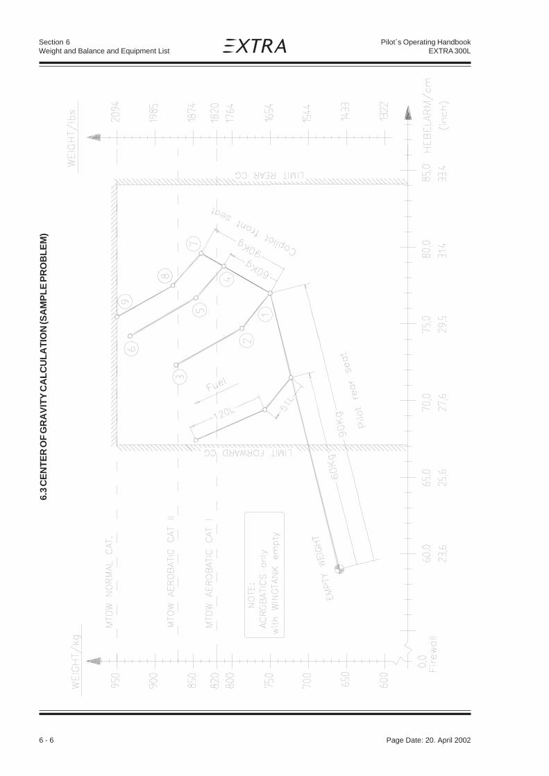
6 - 6 Page Date: 20. April 2002
Section 6Weight and Balance and Equipment List
Pilot´s Operating HandbookEXTRA 300L
6.3
CE
NT
ER
OF
GR
AV
ITY
CA
LC
UL
AT
ION
(SA
MP
LE
PR
OB
LE
M)

Page Date: 20. April 2002 6 - 7
Section 6Weight and Balance and Equipment List
Pilot´s Operating HandbookEXTRA 300L
6.3.1 Sample
Take-off Condition:Pilot On Rear Seat 90.0 kg ( 198.5 lbs)Copilot On Front Seat 90.0 kg ( 198.5 lbs)Acro Fuel 51 L 37.0 kg ( 81.5 lbs)101 L Fuel In Wing Tanks 73.0 kg ( 160.9 lbs)Aircraft Empty Weight 660.0 kg (1455 lbs)
======== ==========950.0 kg (2094.4 lbs)
To find C/G, follow line "Pilot Rear Seat" from Empty Weight to "90 kg" [198.5 lbs] (Point 1).Continue on line "Copilot Front Seat" to 90 kg (Point 7). Now follow line "Fuel" via Point 8(51 L [13.5 US.gal] Acro Fuel) to Point 9 (101 L [26.6 US.gal] Fuel in Wing Tank).
FIND: Weight ~ 950 kg (2094.4 lbs)C/G ~ 75.4 cm (29.6 inch)
6.3.2 Weight and Balance Record Sheet
WEIGHT ARM MOMENT
EMPTY WEIGHT
PILOT
COPILOT
ACRO FUEL
WING FUEL
ΣΣΣΣΣ W = ΣΣΣΣΣ ( W x X ) =
XG = =Σ Σ Σ Σ Σ ( W x X )
ΣΣΣΣΣ W
Page Date: 31. March 2009

6 - 8 Page Date: 20. April 2002
Section 6Weight and Balance and Equipment List
Pilot´s Operating HandbookEXTRA 300L
6.4 LOADING WEIGHTS AND MOMENTS
OCCUPANTS : max. 2
WEIGHT PILOT COPILOT
Pilot REAR SEAT FRONT SEAT+ Parachute Arm = 207cm (81.5 inch) Arm = 98 cm (38.4 inch)
KG LBS KG x CM (IN x LBS) MOMENT KG x CM (IN x LBS)
60 132 12420 (10758) 5880 (5068)
65 143 13455 (11654) 6370 (5491)
70 154 14490 (12551) 6860 (5913)
75 165 15525 (13447) 7350 (6336)
80 176 16560 (14344) 7840 (6758)
85 187 17595 (15240) 8330 (7180)
90 198 18630 (16137) 8820 (7603)
FUEL MAX 171 LITER (45,1 US GAL.)
FUEL
ACRO & CENTER TANK WING TANK
LITER KG KG x CM LITER KG KG x CM(US GAL) (LBS) (LBS x IN) (US GAL) (LBS) (IN x LBS)
9 (2.4) 6.5 (14.3) 182 (157) 10 (2.6) 7.2 (15.9) 360 (313)
20 (5.3) 14.4 (31.8) 420 (365) 20 (5.3) 14.4 (31.8) 721 (629)
25 (6.6) 18.0 (39.7) 529 (459) 40 (10.6) 28.8 (63.5) 1442 (1257)
30 (7.9) 21.6 (47.6) 638 (553) 60 (15.9) 43.2 (95.3) 2164 (1886)
35 (9.2) 25.2 (55.6) 746 (648) 80 (21.1) 57.6 (127.0) 2885 (2514)
40 (10.6) 28.8 (63.5) 855 (742) 100 (26.4) 72.0 (158.8) 3607 (3144)
45 (11.9) 32.4 (71.4) 964 (836) 120 (31.7) 86.4 (190.5) 4328 (3771)
51 (13.5) 36.7 (80.9) 1094 (949)

Page Date: 20. April 2002 6 - 9
Section 6Weight and Balance and Equipment List
Pilot´s Operating HandbookEXTRA 300L
6.5 WEIGHTS AND MOMENTS LIMITS
EXAMPLE:
At 790 KG (1741 LBS) and 64000 kgcm the C/G location is
81.0 cm (31.9") aft of ref datum
Page Date: 20. January 2016

6 - 10 Page Date: 20. April 2002
Section 6Weight and Balance and Equipment List
Pilot´s Operating HandbookEXTRA 300L
6.6 EQUIPMENT LIST
QTY ITEM MANUFACT. PART OR P/N WEIGHT ARM MARK IF REQUIRED (R) (kg) (m) INSTALLED OPTIONAL (O)
ALTERNAT. (A)
1 Engine Textron Lycoming AEIO-540-L1B5 194.90 -0.72 R(R/H) ENPL-RT9609
1 Magneto L/H Slick 6251 or 6351 2.30 -0.15 R1 Magneto R/H Slick 6250 or 6350 2.00 -0.15 R
1 Engine Textron Lycoming AEIO-540-L1B5D 194.90 -0.72 A(R/H) ENPL-RT7471
1 Magnetos Bendix D6LN-3000 5.20 -0.15 A
1 Engine Textron Lycoming AEIO-580-B1A 191.72 -0.72 A(R/H) ENPL-RT10427
1 Magneto L/H Slick 6393 2.30 -0.15 A1 Magneto R/H Slick 6350 2.00 -0.15 A1 Slick Start Unison SS1001 0.27 -0.02 A
4 Shock Mounts Lord J 7764-20 1.70 -0.29 R
4 Shock Mounts Barry Controls 94016-02 1.70 -0.29 A
1 Exhaust System EXTRA/ 63104A0 7.65 -0.40 R6 in 2 Sky Dynamics
2 Exhaust Gomolzig EA300 NSD 9.60 0.80 OSilencer GO3-606500
1 Exhaust System Gomolzig EA300-606000 8.20 -0.39 A6 in 1 with Silencer
1 Fuel Injector Bendix/Precision/ RSA-10 AD 1 3.90 -0.68 RAvstar Lyc. PN: 61M26404
1 Mech. Fuel Pump Crane Lear Romec RG9080-J4A 0.86 -0.15 RLyc. PN: 62E22581
1 Mech. Fuel Pump Hartzell Engine Tech. 200F-5002 0.86 -0.15 ALyc. PN: 62E23186
1 El. Fuel Pump Weldon Tool 8120-M or B8120-M 1.10 -0.04 R
1 Oil Cooler Stewart Warner 8406 R 1.40 -0.90 R
1 2. Oil Cooler Stewart Warner 8406 R 1.40 -0.20 R
1 Low Temperature Extra 83301 0.20 -0.01 ABreather Line Kit
1 Single Oilcooler, rear Niagara NDM 20009A 1.81 -0.22 A
1 Single Oilcooler, rear Aero Classics 8000353 1.65 -0.22 A
1 Set Fuel, Oil & Sens. div. MS28741 with 6.30 -0.21 RHoses in Eng. Comp. firesleeve
1 Set Fuel, Oil & Sens. Parker/Stratoflex PTFE Type 124J 4.90 -0.21 AHoses in Eng. Comp. or Aeroquip or AE466dual Oil Cooler Sys.
1 Set Fuel, Oil & Sens. Parker/Stratoflex PTFE Type 124J 3.70 -0.15 AHoses in Eng. Comp. or Aeroquip or AE466single Oil Cooler Sys.
1 Set Fuel Hoses div. MS28741 2.10 0.45 Rin Cabin Comp.
1 Set Fuel Hoses Parker/Stratoflex PTFE Type 124 1.40 0.45 Ain Cabin Comp. or Aeroquip or 666
1 Set Sens. Hoses Knapp/Hoerbiger HS3MA OR H3MM 0.15 0.82 R(Oil, Fuel & MA Press)
1 RPM Vernier Control ACS Products Co. A-750-30-1200 0.71 0.82 R
1 Mixture Vernier Control ACS Products Co. A-750-20-1080 0.65 0.94 R
EXTRA 300L S/N:
Page Date: 20. January 2016

Page Date: 20. April 2002 6 - 11
Section 6Weight and Balance and Equipment List
Pilot´s Operating HandbookEXTRA 300L
1 Throttle Control Teleflex F303 03250 0.56 0.60 Ror CC330 10'
1 Throttle Control Cable Cablecraft 580-540-501 0.63 0.60 A
1 Propeller MT-Propeller MTV-9-B-C/C200-15 30.40 -1.15 R1 Spinner MT-Propeller P-208-B 0.8 -1.20 R1 Spinner MT-Propeller P-810-2 0.8 -1.20 A
1 Propeller MT-Propeller MTV-14-B-C/C190-17 29.80 -1.15 O1 Spinner MT-Propeller P-238-A 0.8 -1.20 O1 Spinner MT-Propeller P-967 0.8 -1.20 A
1 Propeller MT-Propeller MTV-9-B-C/C198-25 30.50 -1.15 O1 Spinner MT-Propeller P-810-2 0.8 -1.20 O
1 Cowling (GRP) EXTRA 23205.01 & .02 9.80 -0.52 REXTRA 83802.1
1 Cowling (CRP) EXTRA 23205.301 & .302 8.80 -0.52 AEXTRA 83802.1
1 Cowling (CRP) EXTRA 83001.0 9.20 -0.57 A
1 Cowling (GRP) EXTRA 83003.0 10.60 -0.57 A
1 Cowling (CRP) EXTRA 8E001.0 9.20 -0.57 A(incl. Landing Lightprovision)
1 Governor Woodward A- 210 988 1.10 -0.91 R
1 Governor MT-Propeller P-880-5 1.10 -0.91 A
1 Governor MT-Propeller P-880-41 1.10 -0.91 A
7 Switches Cutler Hammer div. 0.28 1.63 R
7 Switches Kissling div. 0.28 1.63 A
11 Circuit Breaker Potter&Brumfield div. 0.50 1.60 R
11 Circuit Breaker ETA or Klixon div. 0.30 1.60 A
1 Main Bus Fuseholder MTA 03.00360 0.03 0.02 O1 Main Bus Strip Fuse MTA 02.00300 O
(40 Amps)
1 PCB Auto Fuse EXTRA 83290.1 0.01 0.03 O
1 Fuel Cont. Probe VDO 226 801 015 001 G 0.12 0.49 RWing Tank
1 Fuel Cont. Probe VDO 224 082 006 097 R 0.20 0.20 RCenter Tank 42 L or 224-011-010-251
1 Fuel Cont. Probe VDO 224 082 007 004 R 0.20 0.44 ACenter Tank 60 L or 224-011-020-372
1 Fuel Cont. Ind. VDO 301 271 036 001 K 0.08 1.62 RWing Tank or 301 030 001 G
1 Fuel Cont. Ind. VDO 301 272 052 001 K 0.14 1.62 RAcro Tank or 301 030 002 G
1 Ammeter VDO 190 004 039 002 0.08 1.62 Ror 190 037 002 G
1 Volt/Ammeter Electronics Intern. VA-1A 0.26 1.62 A
1 Shunt Electronics Intern. S-50 0.09 1.50 A1 Volt/Ammeter Electronics Intern. VA-1A-50 0.22 1.62 A
1 RPM Indicator VDO 333 230 115 002 0.31 1.60 Ror 333 035 001 G
1 RPM Indicator digital Horizon P100-230-643-00 0.68 1.60 A(2700RPM)
QTY ITEM MANUFACT. PART OR P/N WEIGHT ARM MARK IF REQUIRED (R) (kg) (m) INSTALLED OPTIONAL (O)
ALTERNAT. (A)
Page Date: 20. January 2016

6 - 12 Page Date: 20. April 2002
Section 6Weight and Balance and Equipment List
Pilot´s Operating HandbookEXTRA 300L
1 RPM Indicator digital Horizon P100-230-635-00 0.68 1.60 A(2600RPM)
1 Magnetic Compass Airpath C 2300 0.25 1.62 R
1 Magnetic Compass SIRS Navigation Ltd PG2A 0.13 1.62 A
1 Oil Press./ AMITEK or Christen 61943 0.51 1.62 ROil Temp. Ind.
1 Oil Press./ Westach 3DA3-3MM 0.14 1.62 AOil Temp. Ind. (3 1/8") or 3DA3-3KV
1 Oil Temp. Sender Westach W399-S9 0.08 -0.11 A1 Oil Press Sensor Mediamate 387-100MM 0.12 0.04 A
or 387-100KV
1 Oil Press / Westach 2DA3-3MM 0.09 1.62 AOil Temp Ind. (2 1/4") or 2DA3-3KV
1 Oil Temp. Sender Westach W399-S9 0.08 -0.11 A1 Oil Press Sensor Mediamate 387-100MM 0.12 0.04 A
or 387-100KV
1 Oil Press/Oil Temp Ind. UMA D2-OP130U- 0.09 1.62 A(2 1/4") OT300U-01
1 Oil Temp. Probe UMA 1B3A 0.08 -0.11 A1 Oil Press. Sender UMA N1EU150G(-A) or 0.12 0.04 A
T1EU150G(-A)
1 Stall Sensor EXTRA 73106.1 0.07 0.53 R
1 Stall Warning Horn EMAG EM-S 110P 0.13 1.60 R
1 Accelerometer EXTRA DSA 12 0.37 1.60 O
1 Accelerometer Kollsman or Pioneer AN5745 0.40 1.60 Oor Bendix or Jaegeror Century
1 Accelerometer EZE Technologies DA-55 0.16 1.60 O
1 ELT and Antenna Pointer 3000-10 0.90 2.60 O
1 ELT System ARTEX ME-406 1.42 2.60 A
1 Turn & Bank Ind. United Instruments 9501-2 / TSO C3b 0.55 1.63 O
1 Turn & Bank Ind. Castleberry C101 / TSO C101T 0.55 1.63 O
1 Horizon, electric digital RC Allen RCA 2600-2 (0° tilt) 0.24 1.63 O
1 Horizon, electric digital RC Allen RCA 2600-2 (0° tilt) 0.13 1.61 A102-0202-01
1 Horizon, electric digital RC Allen RCA 2600-3 (0° tilt) 0.45 1.63 O
1 Horizon, electric digital RC Allen RCA 2600-3 (0° tilt) 0.19 1.61 A102-0203-01
1 Slip Indicator RC Allen 444-0010-01 0.03 1.63 A(on RCA 2600)
1 Altimeter, front United Instruments UI5934PD-3 A.134 0.39 0.66 O
1 Altimeter, front metric Winter 4110 0.33 0.66 O
1 Altimeter, front metric United Instruments UI5934PD-3M A.665 0.39 0.66 A
1 Altimeter front (ft) Mikrotechna Praha LUN 1128.10B6 0.59 0.65 A
1 Altimeter, rear United Instruments UI5934PD-3 A.134 0.39 1.62 R
1 Altimeter, rear metric Winter 4110 0.33 1.62 A
1 Altimeter, rear metric United Instruments UI5934PD-3M A.665 0.60 1.62 A
1 Altimeter rear (ft) Mikrotechna Praha LUN 1128.10B6 0.59 1.61 A
QTY ITEM MANUFACT. PART OR P/N WEIGHT ARM MARK IF REQUIRED (R) (kg) (m) INSTALLED OPTIONAL (O)
ALTERNAT. (A)
Page Date: 20. January 2016

Page Date: 20. April 2002 6 - 13
Section 6Weight and Balance and Equipment List
Pilot´s Operating HandbookEXTRA 300L
1 Radar Altimeter Anten. FreeFlight TRA 3000 0.68 2.33 O1 incl. Digital Indicator TRI 20 0.34 1.55
1 Altitude Encoder ACK A-30 0.15 1.50 O
1 Airspeed Ind., front Winter 6533-321 0.21 0.65 O
1 Airsp. Ind., front metric Winter 6531-321 0.21 0.65 O
1 Airspeed Ind., front United Instruments UI8030 B.835 0.32 0.65 O
1 Airspeed Ind., front United Instruments UI8030 B.898 0.32 0.65 A(dual scale)
1 Airspeed Ind. front Mikrotechna Praha LUN 1106.K2B4/SC 0.50 0.65 A (kts)
1 Airspeed Ind. front Mikrotechna Praha LUN 1106.P2B4/SC 0.50 0.65 A (km/h)
1 Airspeed Ind., rear Winter 6533-321 0.21 1.61 R
1 Airsp. Ind., rear metric Winter 6531-321 0.21 1.61 A
1 Airspeed Ind., rear United Instruments UI8030 B.835 0.32 1.61 A
1 Airspeed Ind., rear United Instruments UI8030 B.898 0.32 1.61 A(dual scale)
1 Airspeed Ind. rear Mikrotechna Praha LUN 1106.K2B4/SC 0.50 1.61 A(kts)
1 Airspeed Ind. rear Mikrotechna Praha LUN 1106.P2B4/SC 0.50 1.61 A(km/h)
1 Vertical Speed Ind. Winter 5 STVM 15 0.45 1.62 Ametric
1 Vertical Speed Ind. United Instruments UI7030 M C.194 0.35 1.62 Ametric
1 Vertical Speed Ind. United Instruments UI7030 C.27 0.35 1.62 A
1 Vertical Speed Ind. Mikrotechna Praha LUN 1144.B0B1 0.40 1.61 A (fpm)
1 Vertical Speed Ind. Mikrotechna Praha LUN 1144.F0B1 0.40 1.61 A (m/s)
1 EGT/CHT Westach 2 DA 1 0.07 1.62 O1 EGT Probe Westach 712-2 DWK 0.06 -0.37 O1 CHT Probe Westach 712-7 DK 0.05 -0.20 O
1 EGT/CHT Westach EF300/SC-2 DA 1 0.07 1.62 O1 EGT Probe Westach 712-2 DWK 0.06 -0.37 O1 CHT Probe Westach 712-7 D 0.05 -0.20 O
1 EGT/CHT UMA D2-ET1K7K- 0.07 1.62 ACT600J-01
1 EGT Probe UMA 2BU20 0.06 -0.37 A1 CHT Probe UMA 2B18 or 2B02 0.05 -0.20 A
1 EGT/CHT JPI EGT-701 0.41 1.56 O6 EGT Probe JPI M-111 0.35 -0.57 O6 CHT Probe JPI M-113 (S-Plug Gask.) 0.26 -0.56 O1 OAT Probe JPI 400510 0.05 O1 Oil Temp. Probe JPI 400500-L 0.05 -0.22 O1 Manifold Press. Probe JPI 604010 0.05 1.55 O1 RPM Probe JPI 420815-1 0.05 -0.11 O1 Fuel Flow Transducer Flowscan 201-B or FXT-201 0.09 -0.02 O
Shadin 680501 or 680600 0.09 -0.02 A
1 Fuel Scan JPI FS-450 0.12 1.56 O1 Fuel Flow Transducer Flowscan 201-B or FXT-201 0.09 -0.02 O
Shadin 680501 or 680600 0.09 -0.02 A
QTY ITEM MANUFACT. PART OR P/N WEIGHT ARM MARK IF REQUIRED (R) (kg) (m) INSTALLED OPTIONAL (O)
ALTERNAT. (A)
Page Date: 20. January 2016
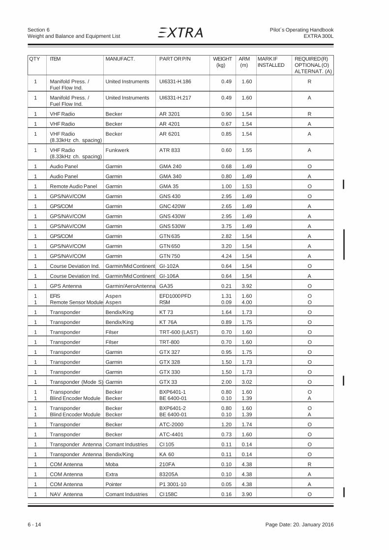
6 - 14 Page Date: 20. April 2002
Section 6Weight and Balance and Equipment List
Pilot´s Operating HandbookEXTRA 300L
QTY ITEM MANUFACT. PART OR P/N WEIGHT ARM MARK IF REQUIRED (R) (kg) (m) INSTALLED OPTIONAL (O)
ALTERNAT. (A)
1 Manifold Press. / United Instruments UI6331-H.186 0.49 1.60 RFuel Flow Ind.
1 Manifold Press. / United Instruments UI6331-H.217 0.49 1.60 AFuel Flow Ind.
1 VHF Radio Becker AR 3201 0.90 1.54 R
1 VHF Radio Becker AR 4201 0.67 1.54 A
1 VHF Radio Becker AR 6201 0.85 1.54 A(8.33kHz ch. spacing)
1 VHF Radio Funkwerk ATR 833 0.60 1.55 A(8.33kHz ch. spacing)
1 Audio Panel Garmin GMA 240 0.68 1.49 O
1 Audio Panel Garmin GMA 340 0.80 1.49 A
1 Remote Audio Panel Garmin GMA 35 1.00 1.53 O
1 GPS/NAV/COM Garmin GNS 430 2.95 1.49 O
1 GPS/COM Garmin GNC 420W 2.65 1.49 A
1 GPS/NAV/COM Garmin GNS 430W 2.95 1.49 A
1 GPS/NAV/COM Garmin GNS 530W 3.75 1.49 A
1 GPS/COM Garmin GTN 635 2.82 1.54 A
1 GPS/NAV/COM Garmin GTN 650 3.20 1.54 A
1 GPS/NAV/COM Garmin GTN 750 4.24 1.54 A
1 Course Deviation Ind. Garmin/Mid Continent GI-102A 0.64 1.54 O
1 Course Deviation Ind. Garmin/Mid Continent GI-106A 0.64 1.54 A
1 GPS Antenna Garmin/AeroAntenna GA35 0.21 3.92 O
1 EFIS Aspen EFD1000 PFD 1.31 1.60 O1 Remote Sensor Module Aspen RSM 0.09 4.00 O
1 Transponder Bendix/King KT 73 1.64 1.73 O
1 Transponder Bendix/King KT 76A 0.89 1.75 O
1 Transponder Filser TRT-600 (LAST) 0.70 1.60 O
1 Transponder Filser TRT-800 0.70 1.60 O
1 Transponder Garmin GTX 327 0.95 1.75 O
1 Transponder Garmin GTX 328 1.50 1.73 O
1 Transponder Garmin GTX 330 1.50 1.73 O
1 Transponder (Mode S) Garmin GTX 33 2.00 3.02 O
1 Transponder Becker BXP6401-1 0.80 1.60 O1 Blind Encoder Module Becker BE 6400-01 0.10 1.39 A
1 Transponder Becker BXP6401-2 0.80 1.60 O1 Blind Encoder Module Becker BE 6400-01 0.10 1.39 A
1 Transponder Becker ATC-2000 1.20 1.74 O
1 Transponder Becker ATC-4401 0.73 1.60 O
1 Transponder Antenna Comant Industries CI 105 0.11 0.14 O
1 Transponder Antenna Bendix/King KA 60 0.11 0.14 O
1 COM Antenna Moba 210FA 0.10 4.38 R
1 COM Antenna Extra 83205A 0.10 4.38 A
1 COM Antenna Pointer P1 3001-10 0.05 4.38 A
1 NAV Antenna Comant Industries CI 158C 0.16 3.90 O
Page Date: 20. January 2016

Page Date: 20. April 2002 6 - 15
Section 6Weight and Balance and Equipment List
Pilot´s Operating HandbookEXTRA 300L
1 Starter B&C Speciality BC 315-100-2 4.63 -0.85 R
1 Starter SKYTEC 149-12LS 3.65 -0.85 A(Lycoming) (31A22 104)
1 Alternator 60 Amps Electrosystems ALX 8421 LS 5.90 -0.86 Rwith bracket
1 Voltage Regul. Lamar B-00371-25 0.15 0.02 R1 Low Volt. Monitor Lamar B-00378-4 R
1 Alternator 65 Amps Bosch 0 120 489 935 4.60 -0.86 A
1 Alternator 55 Amps Bosch 0 120 489 917 4.20 -0.86 A
1 Alternator 55 Amps Bosch 0 120 489 469 4.20 -0.86 A
1 Alternator 65 Amps Prestolite 66021637 4.70 -0.86 A
1 Battery Sonnenschein Dryfit A 212/28G 10.70 0.23 R
1 Battery Concorde RG-25XC 10.40 0.23 A
1 Batt. Charger Plug EXTRA 146 19 20 0.02 0.17 O
1 Ext. Power Recept. Div. AN2552-3A 1.46 1.07 O
1 Ext. Power Solenoid Switches Kidde 22735 0.40 0.03 O
1 Ext. Power Solenoid White-Rodgers 70-111-225-5 0.40 0.03 O(cont. operation)
1 Main Bus Solenoid White-Rodgers 70-111-226-5 0.40 0.03 R
1 Starter Solenoid Switches Kidde 22735 0.40 0.03 R
1 Low Voltage Light OAK MS25041-2 0.02 1.63 R
1 Starter Engaged Light OAK MS25041-4 0.02 1.63 O
1 Ignition Switch TCM 10-357200-1 0.15 1.63 R
2 Wheel Cleveland 40-151 4.00 0.33 R
2 Main Wheel Tires Div 5.00-5 / 6PR 3.90 0.33 R
1 Tail Wheel 5" EXTRA steerable 5.50 5.23 R
1 Tail Wheel 6" Assy Special Products 5.90 5.23 A(Soft) Aviation Inc.
2 Brake Assy Cleveland 30-164 1.40 0.33 R
2 Brake Cyl., front Cleveland 10-20 or 10-20E 0.55 0.15 R
2 Brake Cyl., front Matco MC-4E 0.55 0.15 A
2 Brake Cyl., rear Cleveland 10-20 or 10-20E 0.55 1.15 R
2 Brake Cyl., rear Matco MC-4E 0.55 1.15 A
1 Brake Fluid Reservoir EXTRA 53301.1 0.20 0.03 R
1 Brake Fluid Reservoir ACS A-315 0.20 0.04 A
1 Safety Belt Assy Hooker FK0002 or FK0019 3.30 2.12 RRear Seat (1011230 [3x] &(seat belts w. ratchet, 1113012-1 [1x],shoulder harness, 1H5630-3 [2x]crotch strap) 1CS924-D or -N [1x])
1 Safety Belt Assy Hooker 1011230 [4x], 2.90 1.03 RFront Seat 1H3030-3 [2x](seat belts, 1CS924-D or -N [1x]shoulder harness,crotch strap)
QTY ITEM MANUFACT. PART OR P/N WEIGHT ARM MARK IF REQUIRED (R) (kg) (m) INSTALLED OPTIONAL (O)
ALTERNAT. (A)
Page Date: 20. January 2016

6 - 16 Page Date: 20. April 2002
Section 6Weight and Balance and Equipment List
Pilot´s Operating HandbookEXTRA 300L
1 Safety Belt Assy Hooker FK0004 or FK0020 3.30 1.03 AFront Seat (1011230 [3x] &(seat belts w. ratchet, 1113012-1 [1x],shoulder harness, 1H3030-3 [2x]crotch strap) 1CS924-D or -N [1x])
2 NAV/STROBE LTS Whelen A 600-PG/PR-14 0.23 0.74 R
2 Power Supply Whelen A490T 0.54 0.74 R
1 Landing Light LED Whelen 01-71125-12 0.16 -0.57 O
1 Standard Canopy EXTRA 26301.000-LV 13.50 1.69 R
1 Single Seat EXTRA 86411.011-LV 13.20 1.69 ACanopy
2 Electric Actuator SKF CARR 3.25 0.95 RPedal Adjust. 22x200x1/D12B
1 Long Range Tank EXTRA 86901 1.80 0.55 O
1 Center Tank 42 L EXTRA 66203.001-LK 3.30 0.30 R
1 Center Tank 60 L EXTRA 86713.010-LK 3.90 0.30 A
1 Fuel Selector Allen 6 S 122 0.19 0.73 R
1 Safety Cover EXTRA 86803.1 1.68 3.03 O(Polycarbonate)
1 Dual Pump EXTRA 86100 8.80 0,16 OSmoke Systemwithout Pumps
2 Smoke Oil Pump ITT Jabsco 8860-1203 3.60 0.10 O(Inject. and Refill)
2 Smoke Oil Pump ITT Jabsco 23620-3003 4.40 0.10 O(Inject. and Refill)
1 Smoke Oil Pump Johnson F3B-19 (12V) 2.00 -0.05 O(Injection)
1 Smoke Oil Pump Johnson F2P10-19 (12V) 1.65 0.25 O(Refill)
1 Single Pump EXTRA 86112 9.20 0.30 OSmoke Systemincl. Pump Marco UP3/OIL 12V
1 Airtow Hook EXTRA/TOST 83607A0 0.50 5.42 O
1/2 Sighting Dev. LH/RH EXTRA 83801.10 each 0.54 1.59 O
1 Aresti-Card Holder EXTRA Assy 0.09 1.66 O
2 Wing Tie Down Rings EXTRA 83801.2-01 0.04 1.08 O
1 Remote Mounted Airwolf Filter Corp. AFC-K007 -0.09 OOil Filter Kit
QTY ITEM MANUFACT. PART OR P/N WEIGHT ARM MARK IF REQUIRED (R) (kg) (m) INSTALLED OPTIONAL (O)
ALTERNAT. (A)
Page Date: 20. January 2016

Page Date: 20. April 2002 7 - 1
Section 7Description and Operation of Aircraft and Systems
Pilot´s Operating HandbookEXTRA 300L
Page Date: 20. September 2006
SECTION 7
DESCPRIPTION AND OPERATIONOF AIRCRAFT AND SYSTEMS
Table of Contents
Paragraph PageSECTION 7 DESCPRIPTION AND OPERATION OF AIRCRAFT AND SYSTEMS
7.1 THE AIRCRAFT ................................................................................................................... 7-3
7.2 FUSELAGE ......................................................................................................................... 7-3
7.3 WINGS ................................................................................................................................ 7-4
7.4 EMPENNAGE ...................................................................................................................... 7-4
7.5 FLIGHT CONTROL SYSTEM .............................................................................................. 7-57.5.1 Primary Control System ....................................................................................................... 7-57.5.2 Longitudinal Flight Control System....................................................................................... 7-57.5.3 Lateral Flight Control System............................................................................................... 7-57.5.4 Directional Flight Control System ......................................................................................... 7-57.5.5 Secondary Control ............................................................................................................... 7-5
7.6 INSTRUMENTATION ........................................................................................................... 7-67.6.1 Instrument Panel (Rear Cockpit) .......................................................................................... 7-67.6.2 Instrument Panel (Front Cockpit) .......................................................................................... 7-8
7.7 LANDING GEAR .................................................................................................................. 7-8
7.8 SEATS, SEAT BELTS.......................................................................................................... 7-9
7.9 CANOPY ............................................................................................................................. 7-9
7.10 POWER PLANT .................................................................................................................7-107.10.1 Engine ................................................................................................................................7-107.10.2 Oil System ......................................................................................................................... 7-117.10.3 Engine Installation .............................................................................................................. 7-117.10.4 Propeller ............................................................................................................................. 7-117.10.5 Throttle ............................................................................................................................... 7-117.10.6 Mixture ...............................................................................................................................7-127.10.7 RPM-Control .......................................................................................................................7-127.10.8 Fuel Selector Valve .............................................................................................................7-127.10.9 Exhaust Systems (Optional) ...............................................................................................7-12
7.11 FUEL SYSTEM ...................................................................................................................7-12
7.12 ELECTRICAL SYSTEM ......................................................................................................7-13
7.13 CABIN ENVIRONMENT CONTROL ....................................................................................7-15

7 - 2 Page Date: 20. April 2002
Section 7Description and Operation of Aircraft and Systems
Pilot´s Operating HandbookEXTRA 300L
Left blank intentionally
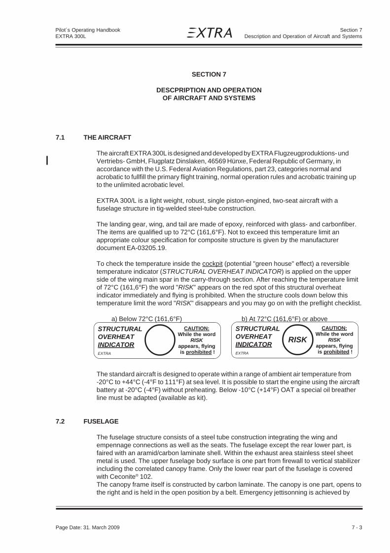
Page Date: 20. April 2002 7 - 3
Section 7Description and Operation of Aircraft and Systems
Pilot´s Operating HandbookEXTRA 300L
SECTION 7
DESCPRIPTION AND OPERATIONOF AIRCRAFT AND SYSTEMS
7.1 THE AIRCRAFT
The aircraft EXTRA 300L is designed and developed by EXTRA Flugzeugproduktions- undVertriebs- GmbH, Flugplatz Dinslaken, 46569 Hünxe, Federal Republic of Germany, inaccordance with the U.S. Federal Aviation Regulations, part 23, categories normal andacrobatic to fullfill the primary flight training, normal operation rules and acrobatic training upto the unlimited acrobatic level.
EXTRA 300/L is a light weight, robust, single piston-engined, two-seat aircraft with afuselage structure in tig-welded steel-tube construction.
The landing gear, wing, and tail are made of epoxy, reinforced with glass- and carbonfiber.The items are qualified up to 72°C (161,6°F). Not to exceed this temperature limit anappropriate colour specification for composite structure is given by the manufacturerdocument EA-03205.19.
To check the temperature inside the cockpit (potential "green house" effect) a reversibletemperature indicator (STRUCTURAL OVERHEAT INDICATOR) is applied on the upperside of the wing main spar in the carry-through section. After reaching the temperature limitof 72°C (161,6°F) the word "RISK" appears on the red spot of this structural overheatindicator immediately and flying is prohibited. When the structure cools down below thistemperature limit the word "RISK" disappears and you may go on with the preflight checklist.
a) Below 72°C (161,6°F) b) At 72°C (161,6°F) or above
The standard aircraft is designed to operate within a range of ambient air temperature from-20°C to +44°C (-4°F to 111°F) at sea level. It is possible to start the engine using the aircraftbattery at -20°C (-4°F) without preheating. Below -10°C (+14°F) OAT a special oil breatherline must be adapted (available as kit).
7.2 FUSELAGE
The fuselage structure consists of a steel tube construction integrating the wing andempennage connections as well as the seats. The fuselage except the rear lower part, isfaired with an aramid/carbon laminate shell. Within the exhaust area stainless steel sheetmetal is used. The upper fuselage body surface is one part from firewall to vertical stabilizerincluding the correlated canopy frame. Only the lower rear part of the fuselage is coveredwith Ceconite® 102.The canopy frame itself is constructed by carbon laminate. The canopy is one part, opens tothe right and is held in the open position by a belt. Emergency jettisonning is achieved by
CAUTION:While the word
RISKappears, flying is prohibited !
STRUCTURALOVERHEATINDICATOREXTRA
RISK
CAUTION:While the word
RISKappears, flying is prohibited !
STRUCTURALOVERHEATINDICATOREXTRA
Page Date: 31. March 2009

7 - 4 Page Date: 20. April 2002
Section 7Description and Operation of Aircraft and Systems
Pilot´s Operating HandbookEXTRA 300L
simply unlatching the canopy. For additional pilot protection a roll bar is installed behind therear pilots seat.
7.3 WINGS
The wing is of CRP construction. The dual chamber main spar - fullfilling the requirement forfail safe design - consists of carbon roving caps combined with CRP webs. Core foam is aPVC foam (Divinycell HT 50). The wing shell is built by a Honeycomb sandwich with CRPLaminates. On the surface there is a protective layer of GRP. To prevent buckling of theshell plywood ribs are used. In the area of the wingtanks is a layer of CRP laminate with anincorporated aluminium thread bonded to the metal fuselage structure as means of lightningprotection.The connection to the fuselage is arranged by two bolts piercing through the spar parallel tothe centerline of the fuselage and two brackets at the rear spars. Integral fuel cells areprovided in the leading edge of the wing extending from the root ribs to half the span of eachR/L and L/H wing. The ailerons are supported at three points in spherical bearings pressedinto aluminium brackets. To reduce pilot's hand forces the hinge line of the ailerons ispositioned 25% of the aileron depth at the root and 21,5% at the tip. Furthermore theailerons are equipped with "spades" to decrease pilot forces. Ailerons are controlled via thecenter bracket. To prevent flutter the ailerons are weight balanced in the overhangingleading edge.
7.4 EMPENNAGE
The EXTRA 300/L possesses a cruziform empennage with stabilizers and moveable controlsurfaces. The rudder is balanced aerodynamically at the tip. Spars consist of PVC foamcores, CRP caps and GRP laminates. The shell is built using honeycomb sandwich withGRP laminates.Deviating from the other control surfaces the spar webs of the surfaces of the elevator isbuilt by CRP. On the R/H elevator half a trim tab is fitted with two hinges. The controlsurfaces are mounted in spherical bearings (exception: Trim tab). To prevent flutter rudderand elevator are mass balanced. The balance weight for the rudder is installed in the ruddertip while the balance weight for the elevator is mounted on the elongated center bracket ofthe elevator extending into the fuselage.
Page Date: 31. March 2009

Page Date: 20. April 2002 7 - 5
Section 7Description and Operation of Aircraft and Systems
Pilot´s Operating HandbookEXTRA 300L
7.5 FLIGHT CONTROL SYSTEM
7.5.1 PRIMARY CONTROL SYSTEM
The EXTRA 300/L is standard equipped with full dual primary flight controls includingconventional stick-type control columns and adjustable rudder pedals. The primary controlsurfaces are operated through a direct mechanical linkage.
7.5.2 LONGITUDINAL FLIGHT CONTROL SYSTEM
The two control columns are interconnected by a torque tube. The control movements arefrom there transferred to the elevator by a push rod.
7.5.3 LATERAL FLIGHT CONTROL SYSTEM
Push and pull rods are connected by sealed ball bearings from the torque tube to theailerons.
The ailerons are statically as well as dynamically balanced (dynamically with spades).
The ailerons are supported by lubricated, sealed bearings.
7.5.4 DIRECTIONAL FLIGHT CONTROL SYSTEM
The dual rudder pedals with brake pedals are adjustable and operate the rudder through acable system. Springs keep the cables under tension when they are not operated.
7.5.5 SECONDARY CONTROL
The elevator trim control is located on the right side in the rear cockpit.
The canopy lock is operated from the outside by a handle on left side of the canopy byreaching into the cockpit through the window. Inside a handle is located in both cockpits,used for locking as well as for normal operation and for emergency release.
The starter/magneto switch is located on the left side of the instrument panel in front of therear seat.

7 - 6 Page Date: 20. April 2002
Section 7Description and Operation of Aircraft and Systems
Pilot´s Operating HandbookEXTRA 300L
7.6 INSTRUMENTATION
The Extra 300/L is equipped with flight instruments in both cockpits.
Instruments and placards can be provided with markings in either metric or English units. Thecolour markings in instruments follow US-FAR, part 23 recommendation ( see section 2 ).
7.6.1 INSTRUMENT PANEL (REAR COCKPIT)
For instrument panel arrangement of the rear cockpit refer to Fig. 7.6.1, which includesstandard and optional equipment marked as such.
Fig. 7.6.1:
1 2 3 4 5 6
15 14 13 12 11 10 9 8 7

Page Date: 20. April 2002 7 - 7
Section 7Description and Operation of Aircraft and Systems
Pilot´s Operating HandbookEXTRA 300L
NOTE
Standard Optional Position Item
x 1 Magneto Selector switch & starterx 2 Amperemeterx 3 Airspeed indicatorx 4 Magn. Direction indicatorx 5 Oil pressure / Oil temperaturex 6 EGT / CHTx 7 COM
x 8 RPM indicatorx 9 Circuit breakerx 10 g-meterx 11 Manifold pressure / Fuel Flowx 12 Altimeterx 13 Master switchx 14 Fuel Quantity Acro Tankx 15 Fuel Quantity Wing Tank
x 16 Vertical speed indicatorx 17 Turn and bank indicatorx 18 Artificial horizonx 19 Fuel pressure
x 20 Intercom buttonx 21 Directional gyro
x 22 RPM control, Prop governorx 23 Mixture controlx 24 Throttle leverx 25 Stickx 26 Radio buttonx 27 Fuel shutoff valvex 28 Trim lever and indicatorx 29 Boost pump
This list may be modified by the minimum equipment requirements of individualcertifying authorities!

7 - 8 Page Date: 20. April 2002
Section 7Description and Operation of Aircraft and Systems
Pilot´s Operating HandbookEXTRA 300L
7.6.2 INSTRUMENT PANEL (FRONT COCKPIT)
Normally the instument panel in the front cockpit is only equipped with the followingpositions.
3 Airspeed indicator12 Altimeter indicator20 Intercom button24 Throttle25 Stick26 Radio button27 Fuel shutoff valve
7.7 LANDING GEAR
The landing gear is a composite construction with a multichamber fiberglass spring in a tail-wheel design.
The main wheels have a size of 5-5.50 and they are equipped with hydraulic disc brakes.
The tail wheel has a solid rubber tire with full-swivel capability.

Page Date: 20. April 2002 7 - 9
Section 7Description and Operation of Aircraft and Systems
Pilot´s Operating HandbookEXTRA 300L
7.8 SEATS, SEAT BELTS
The seats are ergonomically shaped composite designs. The rear seat angle can beadjusted on the ground with 2 quickpins, there are different seat angle possibilities. Theback rest is also adjustable on the ground in different positions and angle. The rear pedal-to-seat distance can be varied in different positions. In the front cockpit there is no possibilityto adjust either the pedals nor the seat. The seat belt assembly consists of a left and a rightshoulder strap, two left and two right lap belts and a negative-g-strap. All belts areadjustable. As each lap belt features a single point release, they are redundant for safetyduring aerobatic maneuvers. If one release is opened unintentionally, the second oneguarantees full safety. For safe operation the releases are arranged in a way that one has tobe closed to the right side, the other one to the left. During acrobatic maneuvers the seatbelt system should be tightened firmly.
7.9 CANOPY
The canopy is manufactured in one section and can be manually operated by interior lockinghandles located on the left side on the canopy.To open the canopy from inside proceed as follows:Pull together the interior locking handles of the front or rear seat and lift canopy to the right.The canopy strap will limit the opening angle.To lock the canopy pull together the interior locking handles and then release.To open the canopy from the outside use the aft interior handles by reaching through thesmall window (bad weather window) and proceed as mentioned above.Generally the emergency operation is equal to the normal procedure. When opening thecanopy in normal flight the low pressure over the canopy will flip the canopy fully openimmediately. However complete jettison of the canopy is possible. In this case the canopycan be finally unlatched at its RH hinge line by the following action:push canopy slightly forward while opening.
Page Date: 31. March 2009

7 - 10 Page Date: 20. April 2002
Section 7Description and Operation of Aircraft and Systems
Pilot´s Operating HandbookEXTRA 300L
7.10 POWER PLANT
7.10.1 ENGINE
The power plant consists of one Textron-Lycoming six-cylinder, horizontally opposed,aircooled, direct drive, fuel injection engine type with inverted oil system.The rated maximum T/O Power is 300 HP at 2700 RPM.
Engine specification: a) Textron - Lycoming AEIO-540-L1B5b) Textron - Lycoming AEIO-540-L1B5D
For the present TBO refer to latest issue of Textron - LycomingSERVICE LETTER No. L 201.
The AEIO-540-L1B5 (D) engine is equipped with special antivibrationcounterweights.
The following accessories are included in the power plantinstallation:
Fuel Injector: BendixMagnetos: SlickAlternator: ElectrosystemsStarter: B&CFuel pump: Gates LearShielded ignition systemPropeller governor driveTransistor voltage regulatorOvervoltage relay
The engine is operated with the following manual controls:
Throttle control, dualRPM controlFuel mixture control
The propeller governor monitors the RPM automaticallyand prevents overspeeding. In the event that oil pressure is lostthe propeller is automatically adjusted to coarse pitch in orderto avoid overspeeding.
The use of 100/130 aviation grade fuel (AVGAS 100) is the minimum graderecommended by the manufacturer of the AEIO-540-L1B5 (D) engine.
For continuous operation 115/145 aviation fuel is the maximumgrade.
Page Date: 15. December 2005

Page Date: 20. April 2002 7 - 11
Section 7Description and Operation of Aircraft and Systems
Pilot´s Operating HandbookEXTRA 300L
7.10.2 OIL SYSTEM
The oil is cooled by a Two Cooler System mounted on the left hand side in the enginecompartment.Alternatively a Single Cooler System is available. In this case the oil is cooled by one oilcooler mounted on the aft, right hand side of the engine.The oil level is determined by a dip-stick.
A thermostatic valve is fitted upstream of the oil cooler. This valve ensures a quick warm-upof the oil after engine start.
Oil capacity and grades:
Max sump capacity 16 qts.Min sump capacity 9 qts.
For temperatures and oil grades refer to Section 1.7.
7.10.3 ENGINE INSTALLATION
The engine is supported by four shock mounts (type LORD or BARRY CONTROLS), to thetig-welded steel tube engine mount which is attached to the fuselage with four bolts on thefirewall axis.
The engine cowling is divided into two parts, a lower and an upper part both made of glass-fibre/carbonfibre reinforced epoxy. The parts are fixed by a number of screws and the uppercowling has a separate hatch for easy access to the oil dip-stick.
7.10.4 PROPELLER
The standard propeller is a 3-blade wood composite, constant speed propellertype MTV-9-B-C/C200-15. The propeller has a diameter of 2,0 m (78.74 in.). A 4-blade propellertype MTV-14-B-C/C190-17 with a diameter of 1,9 m (74.8 in.) is also available as an alternative.
7.10.5 THROTTLE
Dual control mounted on the left side of the cockpit.
Page Date: 20. January 2016

7 - 12 Page Date: 20. April 2002
Section 7Description and Operation of Aircraft and Systems
Pilot´s Operating HandbookEXTRA 300L
7.10.6 MIXTURE
Vernier-control located at the left side of the rear cockpit (red knob).
7.10.7 RPM-CONTROL
Vernier-control on the left side of the rear cockpit.Preselection of RPM possible due to constant speed governor (blue knob).
7.10.8 FUEL SELECTOR VALVE
Dual control. A rotary fuel selector valve is mounted behind the firewall on the right side of thefuselage. A torque tube connects the valve to both cockpit handles. Pull and turn the handle90° to open the valve to the Acro & Center tank. A further 90° turn switches to the Wing tankfuel supply.
Position down = CLOSEDPosition left = ACRO & CENTER TANKPosition up = WING TANK
7.10.9 EXHAUST SYSTEMS (OPTIONAL)
Optionally the EA 300/L can be equipped with an additional silencer system type Gomolzig.The attachment is integrated in the fuselage structure. Thus no modifications are necessaryto install the silencer system.Alternatively a complete 6 in 1 System with integrated silencer is available.
7.11 FUEL SYSTEM
The fuel system consists of two separate, independent tanks:- Acro & center tank in the fuselage- Wing tank (LH and RH)
Wing tank:The root section of each wing - in front of main spars forms an integral fuel tank providingtwo interconnected tanks with 120 liters (31,7 US GAL.) total capacity. Each side of the winghas a 2" diameter filler cap for gravity refueling. The wing tank can be completely emptied inflight.
Acro & center tank:An Acro tank 9 liters (2,3 US Gal.) is mounted in the fuselage just behind the firewall andthe Center tank 42 liters (11,1US Gal.) in front of the main spar of the wing. The Acro tankis connected with the center tank in a gravity feed system. The center tank has a 2"diameter filler cap for gravity refueling. Unusable fuel is approximately 5.5 liters (1.45 USGal.)
Adequate venting is provided in each tank to a main ventilation-tube, ending outside thefuselage at the right side.
In addition to the engine driven fuelpump an electrically driven auxiliary fuel pump (boostpump) with by-pass and having sufficient capacity to feed the engine at take-off power isfitted as a safety device against failure of the engine-driven pump. The boost pump switchis located on the instrument panel.
Page Date: 15. December 2005

Page Date: 20. April 2002 7 - 13
Section 7Description and Operation of Aircraft and Systems
Pilot´s Operating HandbookEXTRA 300L
A fuel filter with drain is installed between the fuel selector valve and the boost pump.Separate drains are located at the lowest point of each tank system.
Normal float type transducers and electrically operated fuel indicators are used.
7.12 ELECTRICAL SYSTEM
The electrical system is supplied by a 12 V alternator with rectifier, transistor voltageregulator. The alternator is mounted on and driven by the engine.
The field current is controlled by the voltage regulator to nominal 14 V under all loadconditions. The masterswitch is located on the rear instrument panel.
Circuit protection against overvoltage is provided by the voltage regulator.
The maximum load taken from the alternator is 40 amp.
A 12 V leak proof battery is connected across the alternator output to stabilize the supplyand to maintain all essential services in the event of an alternator failure and when theengine is not operating. The battery is mounted behind the firewall.
All electrical circuits are protected by circuit breakers located on the rear instrument paneland they are easily accessible to the pilot during flight.
The electrical system is adequately suppressed to ensure satisfactory operation of the radioequipment.
All wires, switches, circuit breakers etc. are manufactured to related aeronauticalspecifications.
Page Date: 15. December 2005

7 - 14 Page Date: 20. April 2002
Section 7Description and Operation of Aircraft and Systems
Pilot´s Operating HandbookEXTRA 300L
Sta
ndar
d an
d O
ptio
nal E
quip
men
t sho
wn
Page Date: 08. October 2009
SC
HE
MA
TIC
E
LEC
TR
ICA
L S
YS
TE
M

Page Date: 20. April 2002 7 - 15
Section 7Description and Operation of Aircraft and Systems
Pilot´s Operating HandbookEXTRA 300L
7.13 CABIN ENVIRONMENT CONTROL
A ventilation system in the canopy on the left side is provided for the supply of fresh air tothe cabin. Left and right at the rear seat are eyeball-type adjustable vents.

7 - 16 Page Date: 20. April 2002
Section 7Description and Operation of Aircraft and Systems
Pilot´s Operating HandbookEXTRA 300L
Left blank intentionally

Page Date: 20. April 2002 8 - 1
Section 8Handling, Servicing and Maintenance
Pilot´s Operating HandbookEXTRA 300L
SECTION 8
HANDLING, SERVICING AND MAINTENANCE
TABLE OF CONTENTS
Paragraph PageSECTION 8 HANDLING, SERVICING AND MAINTENANCE
8.1 INTRODUCTION................................................................................................................. 8-3
8.2 AIRPLANE INSPECTION PERIODS................................................................................... 8-3
8.3 PILOT CONDUCTED PREVENTIVE MAINTENANCE ....................................................... 8-3
8.4 ALTERATIONS OR REPAIR ............................................................................................... 8-3
8.5 SERVICING......................................................................................................................... 8-4
8.6 GROUND HANDLING......................................................................................................... 8-4

8 - 2 Page Date: 20. April 2002
Section 8Handling, Servicing and Maintenance
Pilot´s Operating HandbookEXTRA 300L
Left blank intentionally

Page Date: 20. April 2002 8 - 3
Section 8Handling, Servicing and Maintenance
Pilot´s Operating HandbookEXTRA 300L
SECTION 8
HANDLING, SERVICING AND MAINTENANCE
8.1 INTRODUCTION
a) The airplane owner should establish contact with the dealer or certified service stationfor service and information.
b) All correspondence regarding the airplane must include its serial number which isstamped on a plate on the L/H rear part of the fuselage.
c) A service manual with revision service may be procured from the manufacturer.
8.2 AIRPLANE INSPECTION PERIODS
As required by national operating rules all airplanes must pass a complete annualinspection every twelve calendar months. In addition to the annual inspection airplanesmust pass a complete inspection after every 100 flights hours with a minor check after 50hours.
The Airworthiness Authority may require other inspections by the issuance of airworthinessdirectives applicable to the aircraft, engine, propeller and components. The owner isresponsible for compliance with all applicable airworthiness directives and periodicalinspections.
8.3 PILOT CONDUCTED PREVENTIVE MAINTENANCE
Pilots operating the airplane should refer to the regulations of the country of certification forinformation of preventive maintenance that may be performed by pilots. All othermaintenance required on the airplane is to be accomplished by appropriately licensedpersonnel. Airplane dealer should be contacted for further information
Preventive maintenance should be accomplished with the appropriate service manual.
8.4 ALTERATIONS OR REPAIR
Alterations or repairs of the airplane must be accomplished by licensed personel.

8 - 4 Page Date: 20. April 2002
Section 8Handling, Servicing and Maintenance
Pilot´s Operating HandbookEXTRA 300L
8.5 SERVICING
In addition to the airplane inspection periods (8.2) information for servicing the aircraft withproper oil and fuel is covered in Section 2 (Limitations) and Section 7 (Description andOperation).
8.6 GROUND HANDLING
a) Due to its low weight and the free swiveling tail wheel two persons can easily move theairplane by hand.
b) To tie down the airplane M6 nut plates are provided in the wing tips where ring bolts canbe screwed in. The tail wheel leg can be used as third point to tie down the airplane.If the aircraft is parked in the open, it must be protected against the effects of weather, thedegree of protection depending on severity of the weather conditions and the expectedduration of the parking period. When the airplane is parked in good weather conditions forless than a half day park the aircraft headed into the wind and place wheel chocks at themain wheels.
c) To level the aircraft, the tail wheel is rested on a balance and jacked to a position that thefuselage reference line (upper fuselage stringer tube) is horizontal. There are two enginehoists provided on the top of the engine which can be used to lift the airplane with a crane.(Tail wheel resting on ground)
Page Date: 20. April 2002 9 - 1
Section 9Supplements
Pilot´s Operating HandbookEXTRA 300L
SECTION 9 SUPPLEMENTS
9 SUPPLEMENTS ....................................................................................................................... 3
Page Date: 5. December 2008
SECTION 9
SUPPLEMENTSDoc-No. EA-06701.1
Table of Contents
Section Pages
9 Supplements ............................................................................................................. 4 p.
901 Steerable Tail Wheel ............................................................................................... 4 p.
902 Electric Pedal Adjustment ....................................................................................... 4 p.
903 Electronic Accelerometer ........................................................................................ 10 p.
904 Emergency Locator Transmitter.............................................................................. 8 p.
905 External Power ......................................................................................................... 6 p.
906 Digital RPM Indicator ............................................................................................... 6 p.
907 Long Range Wing Tank Capacity ........................................................................... 6 p.
908 Airtow Hook ............................................................................................................... 8 p.
909 Smoke System .......................................................................................................... 6 p.
910 ACRO III Category..................................................................................................... 8 p.
911 Single Seat Canopy ................................................................................................. 4 p.
912 FILSER TRT 600 Transponder .................................................................................. 8 p.
913 FILSER TRT 800 Transponder .................................................................................. 8 p.
914 GARMIN GTX 327 Transponder ............................................................................... 6 p.
915 GARMIN GTX 330 Transponder ............................................................................... 8 p.
916 BENDIX/KING KT 76A Transponder ......................................................................... 6 p.
917 BENDIX/KING KT 73 Transponder ........................................................................... 8 p.
918 BECKER ATC 2000 Transponder .............................................................................. 6 p.
919 BECKER ATC 4401 Transponder .............................................................................. 8 p.
920 BECKER BXP 6401 Transponder.............................................................................. 10 p.
921 Lycoming AEIO-580-B1A Engine.............................................................................. 14 p.
922 Center Tank Increased Capacity ............................................................................. 8 p.
923 GARMIN GTX 328 Transponder ............................................................................... 8 p.

9 - 2 Page Date: 20. April 2002
Section 9Supplements
Pilot´s Operating HandbookEXTRA 300L
924 ASPEN EFD1000 PILOT PFD ................................................................................... 12 p.
925 GARMIN GNC 420W ................................................................................................. 8 p.
926 ARTEX ME-406 ELT .................................................................................................. 8 p.
927 AIRPLANES REGISTERED IN BRAZIL AND OPERATING UNDER THEAGÊNCIA NACIONAL DE AVIAÇÃO CIVIL REQUIREMENTS ................................. 6 p.
928 LANDING LIGHT LED ............................................................................................... 4 p.
929 GARMIN GTN 635/650/750........................................................................................ 16 p.
Page Date: 20. January 2016

Page Date: 20. April 2002 9 - 3
Section 9Supplements
Pilot´s Operating HandbookEXTRA 300L
9 SUPPLEMENTS
9.1 Introduction
Section 9 "Supplements" of the Pilot´s Operating Handbook contains all information, neces-sary for a safe and efficient operation of the airplane when equipped with one or more of thevarious optional systems and equipment not provided with the standard airplane.
9.2 Notes
The described systems and equipment are certified by the EASA for the EXTRA 300/L. Pagesand contents of this section must not be exchanged and alterations of or additions to theapproved contents must not be made without the EXTRA Flugzeugproduktions- und Vertriebs-GmbH/EASA approval. The editor has the copyright of these Supplements and is responsiblefor edition of revisions. The log of effective pages is found on the preceding pages of this Pilot´sOperating Handbook.
Each Supplement section (e.g. steerable tailwheel) covers only a single system, device, orpiece of equipment and is a self-contained, miniature Pilot´s Operating Handbook. The owner isresponsible for incorporating prescribed amendments and should make notes about these onthe records of amendments. It is responsibility of the pilot to be familiar with the contents ofrelevant supplements.
POH Supplements must be in the airplane for flight operations when the subject equipment isinstalled or special operations are to be performed.
The Table of Contents shows all EXTRA Supplements available for the EXTRA 300/L. A checkmark in the Section column indicates that the corresponding supplement must be included inthis POH.
Page Date: 31. March 2009

9 - 4 Page Date: 20. April 2002
Section 9Supplements
Pilot´s Operating HandbookEXTRA 300L
Left blank intentionally

Page Date: 20. April 2002 901 - 1
Section 901Steerable Tail Wheel
Pilot´s Operating HandbookEXTRA 300L
SECTION 901
STEERABLE TAIL WHEEL
Table of Contents
Paragraph PageSECTION 901 STEERABLE TAIL WHEEL
901.1 GENERAL ....................................................................................................................... 901-3
901.2 LIMITATION .................................................................................................................... 901-3
901.3 EMERGENCY PROCEDURES ....................................................................................... 901-3
901.4 NORMAL PROCEDURES............................................................................................... 901-3
901.5 PERFORMANCE ............................................................................................................ 901-3
901.6 WEIGHT AND BALANCE ............................................................................................... 901-3
901.7 DESCRIPTION OF THE SYSTEM .................................................................................. 901-3
901.8 HANDLING, SERVICING AND MAINTENANCE ............................................................. 901-4

901 - 2 Page Date: 20. April 2002
Section 901Steerable Tail Wheel
Pilot´s Operating HandbookEXTRA 300L
Left blank intentionally

Page Date: 20. April 2002 901 - 3
Section 901Steerable Tail Wheel
Pilot´s Operating HandbookEXTRA 300L
901 STEERABLE TAIL WHEEL
901.1 GENERAL
To improve taxi and handling quality, the EXTRA 300/L can be equipped with an optionalsteerable tailwheel. The deflection angle of this tailwheel is arranged by the rudder controlup to plus/minus 30°. Exceeding this deflection the tailwheel has a full-swivel capability by arelease mechanism.
901.2 LIMITATION
The operation limitations are not effected due to the use of the steerable tailwheel.
901.3 EMERGENCY PROCEDURES
There is no change of basic emergency procedures with the installation of the steerabletailwheel.
901.4 NORMAL PROCEDURES
There are no changes for the described normal procedures after installation of the steerabletailwheel. In addition to the existing normal procedures the light precompression of connec-tor springs and movement of the rudder have to be checked during the preflight check.
901.5 PERFORMANCE
Changes in flight performance due to installation of the steerable tailwheel are not notice-able. The given basic performance data under section 5 are still valid.
901.6 WEIGHT AND BALANCE
A change of the running empty weight and resulting C/G position after installation of thesteerable tailwheel is neglectable, because of minor differences in weight and C/G betweenstandard and optional steerable tailwheel.
901.7 DESCRIPTION OF THE SYSTEM
The 5 inch tailwheel has a solid rubber tire and is rotatable by means of a wheelfork, whichis connected to a bearing steelsleeve. This steelsleeve itself contains also the releasemechanic, which gives the wheelfork a full-swivel capability exceeding plus/minus 30°deflection. The steelsleeve is glued into the glasfiberspring, which is bolted to the tailhardpoint of the aircraft. The steering of the tailwheel is accomplished by a direct mechaniclink (rudder control cable) from the rudder pedals. The steering deflection of the tailwheel iscontrolled by the rudder movement and dampened by anti shimmy connector springs.

901 - 4 Page Date: 20. April 2002
Section 901Steerable Tail Wheel
Pilot´s Operating HandbookEXTRA 300L
901.8 HANDLING, SERVICING AND MAINTENANCE
During 50 hour inspection, the bearing steelsleeve has to be lubricated on the point oflubricating. Additionally all parts of the tailwheel have to be inspected visually for deforma-tions, cracks and corrosion.

Page Date: 20. April 2002 902 - 1
Section 902Electric Pedal Adjustment
Pilot´s Operating HandbookEXTRA 300L
SECTION 902
ELECTRIC PEDAL ADJUSTMENT
Table of Contents
Paragraph PageSECTION 902 ELECTRIC PEDAL ADJUSTMENT
902.1 GENERAL ........................................................................................................................ 902-3
902.2 LIMITATIONS ................................................................................................................... 902-3
902.3 EMERGENCY PROCEDURES ........................................................................................ 902-3
902.4 NORMAL PROCEDURES ................................................................................................ 902-3
902.5 PERFORMANCE.............................................................................................................. 902-3
902.6 WEIGHT AND BALANCE ................................................................................................ 902-3
902.7 DESCRIPTION OF THE SYSTEM ................................................................................... 902-3
902.8 HANDLING, SERVICING AND MAINTENANCE .............................................................. 902-4

902 - 2 Page Date: 20. April 2002
Section 902Electric Pedal Adjustment
Pilot´s Operating HandbookEXTRA 300L
Left blank intentionally

Page Date: 20. April 2002 902 - 3
Section 902Electric Pedal Adjustment
Pilot´s Operating HandbookEXTRA 300L
902 ELECTRIC PEDAL ADJUSTMENT
902.1 GENERAL
To improve seat and control convenience, the EXTRA 300/L can be equipped with anoptional elect. pedal adjustment system. The pedal adjustment system provides an in-flightcapability to adjust the pedals according the pilots size and operation. For example a morerelaxed, stretched seating position for long cross-country flights is possible.
902.2 LIMITATIONS
An adjustment of the pedal position during takeoff and landing is not allowed.
902.3 EMERGENCY PROCEDURES
In case of an electric failure occurs during adjustment procedure (e.g. unintentional contin-ued adjustment by failure of a control switch), try to move the pedals to the opposite direc-tion immediately. If this measure is unsuccessful, the circuit breaker has to be pulled withoutdelay. The relative low actuation velocity enables the pilot to sufficient rudder control input.
902.4 NORMAL PROCEDURES
Check rudder control system for impeccable, easy operation during preflight inspection. Forthat purpose the pedals have to be adjusted to a position, which allows full control inputs ofrudder and aileron simultaneously as well as full rudder control input in conjunction with fullapplied brakes. the pedals may be stepless adjusted inflight independently by two switcheslocated on the instrument panel. Pay attention to symmetrical adjustment of left and rightpedal.
902.5 PERFORMANCE
Not affected.
902.6 WEIGHT AND BALANCE
Not affected.
902.7 DESCRIPTION OF THE SYSTEM
The optional electrical pedal adjustment system which is guided on slide tubes, replaces therear mechanical rudder pedal adjustment. Such a pedal system consists of a foot rest andthe rudder pedal itself, including brake pedal and brake cylinder. An S-shaped cable leaderis attached to the rudder pedal, through which the control cable runs from the rudder actua-tor arm to the front cable attachment at the steel frame. The connection to the front seatpedals is realized by a further cable, which is fixed to the control cable by two Nicopress ovalsleeves. The stepless pedal adjustment is realized by electromechanical actuators which arecontrolled separately by switches on the rear instrument panel (refer to figure below). Thetotal travel of the system is limited to 6.3" by a front and a rear stop switch at the slide tube

902 - 4 Page Date: 20. April 2002
Section 902Electric Pedal Adjustment
Pilot´s Operating HandbookEXTRA 300L
attachment. A full travel from the most rearward to the most forward position takes approxi-mately 15sec.
902.8 HANDLING, SERVICING AND MAINTENANCE
Not affected.
FORWARD
BACKLH --------- RH
PEDALADJUST
PEDAL-ADJUST.
CONTROL-SWITCHES
CIRCUIT BREAKER 7.5A
Page Date: 8. October 2009

Page Date: 20. April 2002 903 - 1
Section 903Electronic Accelerometer
Pilot´s Operating HandbookEXTRA 300L
SECTION 903
ELECTRONIC ACCELEROMETER
Table of Contents
Paragraph PageSECTION 903 ELECTRONIC ACCELEROMETER
903.1 GENERAL ....................................................................................................................... 903-3
903.2 LIMITATIONS .................................................................................................................. 903-3
903.3 EMERGENCY PROCEDURES ....................................................................................... 903-3
903.4 NORMAL PROCEDURES............................................................................................... 903-3
903.5 PERFORMANCE ............................................................................................................ 903-3
903.6 WEIGHT AND BALANCE ............................................................................................... 903-3
903.7 DESCRIPTION AND OPERATION OF THE SYSTEM .................................................... 903-3
903.8 HANDLING, SERVICING AND MAINTENANCE ............................................................. 903-9

903 - 2 Page Date: 20. April 2002
Section 903Electronic Accelerometer
Pilot´s Operating HandbookEXTRA 300L
Left blank intentionally

Page Date: 20. April 2002 903 - 3
Section 903Electronic Accelerometer
Pilot´s Operating HandbookEXTRA 300L
903 ELECTRONIC ACCELEROMETER
903.1 GENERAL
The standard equipped accelerometer typ AN 5745 can be replaced by an optional"Digital Solid State Accelerometer DSA 12".
903.2 LIMITATIONS
The instrument markings and placards are provided for the acrobatic category (1 seat) only;for the acrobatic category (2 seat) and for the normal category refer to correspondinglimitations.Any exceedance of given limitations have to be reported by the pilot and considered bycorresponding maintenance or inspection procedure according to the SERVICE MANUALEA 300/L.
Instrument markings
Electronic Accelerometer DSA 12
red range -12 g - -10 gyellow range > -10 g - -8 ggreen range > -8 g - < +8 gyellow range + 8 g - < +10 gred range +10 g - +12 g
903.3 EMERGENCY PROCEDURES
Not affected.
903.4 NORMAL PROCEDURES
Not affected.
903.5 PERFORMANCE
Not affected.
903.6 WEIGHT AND BALANCE
Not affected.
903.7 DESCRIPTION AND OPERATION OF THE SYSTEM
The DSA 12 accelerometer measures acceleration in one certain direction. The measuringrange is between +20g and -20g. A clock inside the instrument measures time and date.One of the output-displays is an LCD with two lines and eight positions per line. Positivevalues of accelerations are always shown in the upper line of the LCD, and negative valuesof acceleration always in the bottom line.
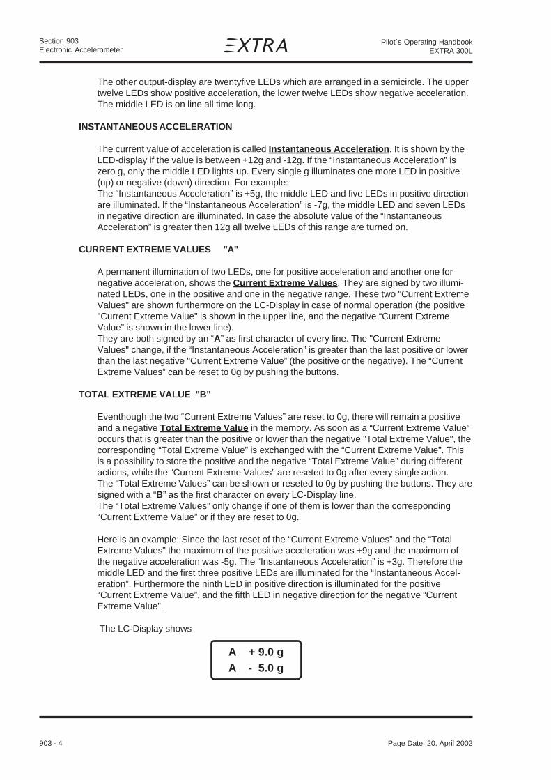
903 - 4 Page Date: 20. April 2002
Section 903Electronic Accelerometer
Pilot´s Operating HandbookEXTRA 300L
The other output-display are twentyfive LEDs which are arranged in a semicircle. The uppertwelve LEDs show positive acceleration, the lower twelve LEDs show negative acceleration.The middle LED is on line all time long.
INSTANTANEOUS ACCELERATION
The current value of acceleration is called Instantaneous Acceleration. It is shown by theLED-display if the value is between +12g and -12g. If the “Instantaneous Acceleration” iszero g, only the middle LED lights up. Every single g illuminates one more LED in positive(up) or negative (down) direction. For example:The “Instantaneous Acceleration” is +5g, the middle LED and five LEDs in positive directionare illuminated. If the “Instantaneous Acceleration” is -7g, the middle LED and seven LEDsin negative direction are illuminated. In case the absolute value of the “InstantaneousAcceleration” is greater then 12g all twelve LEDs of this range are turned on.
CURRENT EXTREME VALUES "A"
A permanent illumination of two LEDs, one for positive acceleration and another one fornegative acceleration, shows the Current Extreme Values. They are signed by two illumi-nated LEDs, one in the positive and one in the negative range. These two "Current ExtremeValues" are shown furthermore on the LC-Display in case of normal operation (the positive"Current Extreme Value" is shown in the upper line, and the negative “Current ExtremeValue” is shown in the lower line).They are both signed by an “A” as first character of every line. The "Current ExtremeValues" change, if the “Instantaneous Acceleration” is greater than the last positive or lowerthan the last negative "Current Extreme Value” (the positive or the negative). The “CurrentExtreme Values” can be reset to 0g by pushing the buttons.
TOTAL EXTREME VALUE "B"
Eventhough the two “Current Extreme Values” are reset to 0g, there will remain a positiveand a negative Total Extreme Value in the memory. As soon as a “Current Extreme Value”occurs that is greater than the positive or lower than the negative "Total Extreme Value", thecorresponding “Total Extreme Value” is exchanged with the “Current Extreme Value”. Thisis a possibility to store the positive and the negative “Total Extreme Value” during differentactions, while the “Current Extreme Values” are reseted to 0g after every single action.The “Total Extreme Values” can be shown or reseted to 0g by pushing the buttons. They aresigned with a “B” as the first character on every LC-Display line.The “Total Extreme Values” only change if one of them is lower than the corresponding“Current Extreme Value” or if they are reset to 0g.
Here is an example: Since the last reset of the “Current Extreme Values” and the “TotalExtreme Values” the maximum of the positive acceleration was +9g and the maximum ofthe negative acceleration was -5g. The “Instantaneous Acceleration” is +3g. Therefore themiddle LED and the first three positive LEDs are illuminated for the “Instantaneous Accel-eration”. Furthermore the ninth LED in positive direction is illuminated for the positive“Current Extreme Value”, and the fifth LED in negative direction for the negative “CurrentExtreme Value”.
The LC-Display shows
A + 9.0 g
A - 5.0 g

Page Date: 20. April 2002 903 - 5
Section 903Electronic Accelerometer
Pilot´s Operating HandbookEXTRA 300L
After resetting the “Current Extreme Values”, the LC-Display shows
A + 3.0 g
A - 0.0 g
and only the middle LED and three LEDs in the positive range of the LED-Display areshining. If the display presents the “Total Extreme Value” you will see
A + 9.0 g
A - 5.0 g
on the LC-Display, because the “Total Extreme Values” has not changed.
The “Total Extreme Values” only change if one of them is lower than the corresponding“Current Extreme Value” or if they are reset to 0g.
ABSOLUTE EXTREME VALUES "C"
Two further extreme acceleration values are the positive and the negative AbsoluteExtreme Value. These values are the greatest acceleration values that ever occurred. Theycan not be reset and they are stored in the long-term memory inside the instrument.Additionally, time and date these “Absolute Extreme Values” occurred are stored. Thesedates can be shown by the LC-Display by pushing the buttons.The Output of the “Absolute Extreme Values” is signed by a “C” as first character of the twoLC-Display lines. The “Absolute Extreme Values” only change, if an “Instantaneous Value”occurs that is greater than the positive “Absolute Extreme Value” or lower than the negative“Absolute Extreme Value”.
TIME AND DATE
You can recall the current time and date by pushing the buttons. If you want to change thecurrent time and date of the clock, you have to enter the security code by the buttons. InCase the code is wrong or you wait too long, the instrument will return into the “NormalOperating Mode”. The clock module has its own battery power supply backup, preventingthe clock from stopping even in case of turning off the master switch or disconnecting theDSA 12 from the electrical system of the aircraft.
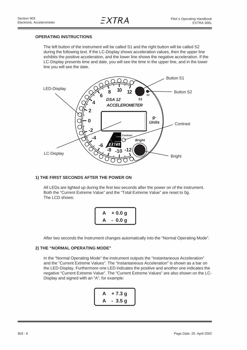
903 - 6 Page Date: 20. April 2002
Section 903Electronic Accelerometer
Pilot´s Operating HandbookEXTRA 300L
OPERATING INSTRUCTIONS
The left button of the instrument will be called S1 and the right button will be called S2during the following text. If the LC-Display shows acceleration values, then the upper lineexhibits the positive acceleration, and the lower line shows the negative acceleration. If theLC-Display presents time and date, you will see the time in the upper line, and in the lowerline you will see the date.
1) THE FIRST SECONDS AFTER THE POWER ON
All LEDs are lighted up during the first two seconds after the power on of the instrument.Both the “Current Extreme Value” and the “Total Extreme Value” are reset to 0g.The LCD shows:
A + 0.0 g
A - 0.0 g
After two seconds the Instrument changes automatically into the “Normal Operating Mode”.
2) THE “NORMAL OPERATING MODE”
In the “Normal Operating Mode” the instrument outputs the “Instantaneous Acceleration”and the “Current Extreme Values”. The “Instantaneous Acceleration” is shown as a bar onthe LED-Display. Furthermore one LED indicates the positive and another one indicates thenegative “Current Extreme Value”. The “Current Extreme Values” are also shown on the LC-Display and signed with an “A”, for example:
A + 7.3 g
A - 3.5 g
4
2
0
-2
-4
-6
6DSA 12 ACCELEROMETER
g-Units
S2
S1
-10 -12-8
Bright
Contrast
10 128
Button S1
Button S2
Contrast
LC-Display
LED-Display
Bright
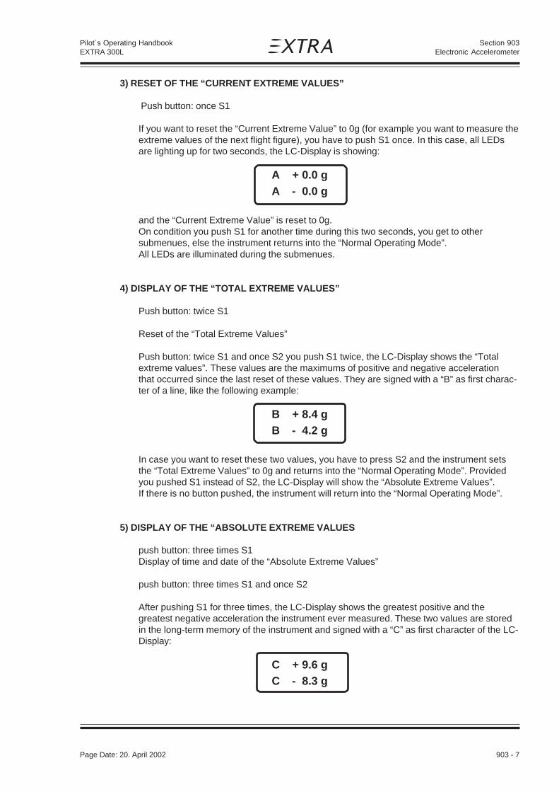
Page Date: 20. April 2002 903 - 7
Section 903Electronic Accelerometer
Pilot´s Operating HandbookEXTRA 300L
3) RESET OF THE “CURRENT EXTREME VALUES”
Push button: once S1
If you want to reset the “Current Extreme Value” to 0g (for example you want to measure theextreme values of the next flight figure), you have to push S1 once. In this case, all LEDsare lighting up for two seconds, the LC-Display is showing:
A + 0.0 g
A - 0.0 g
and the “Current Extreme Value” is reset to 0g.On condition you push S1 for another time during this two seconds, you get to othersubmenues, else the instrument returns into the “Normal Operating Mode”.All LEDs are illuminated during the submenues.
4) DISPLAY OF THE “TOTAL EXTREME VALUES”
Push button: twice S1
Reset of the “Total Extreme Values”
Push button: twice S1 and once S2 you push S1 twice, the LC-Display shows the “Totalextreme values”. These values are the maximums of positive and negative accelerationthat occurred since the last reset of these values. They are signed with a “B” as first charac-ter of a line, like the following example:
B + 8.4 g
B - 4.2 g
In case you want to reset these two values, you have to press S2 and the instrument setsthe “Total Extreme Values” to 0g and returns into the “Normal Operating Mode”. Providedyou pushed S1 instead of S2, the LC-Display will show the “Absolute Extreme Values”.If there is no button pushed, the instrument will return into the “Normal Operating Mode”.
5) DISPLAY OF THE “ABSOLUTE EXTREME VALUES
push button: three times S1Display of time and date of the “Absolute Extreme Values”
push button: three times S1 and once S2
After pushing S1 for three times, the LC-Display shows the greatest positive and thegreatest negative acceleration the instrument ever measured. These two values are storedin the long-term memory of the instrument and signed with a “C” as first character of the LC-Display:
C + 9.6 g
C - 8.3 g

903 - 8 Page Date: 20. April 2002
Section 903Electronic Accelerometer
Pilot´s Operating HandbookEXTRA 300L
Additionally the long-term memory stores the times and dates when new “Absolute ExtremeValues” occur. They are shown if you push S2 next. In this case during the next twelveseconds the LC-Display shows under the title “MAX-DATE” the time and date of the positive “Absolute Extreme Value” and under the title “MIN-DATE” the time and date of thenegative “Absolute Extreme Value”. Afterwards the instrument returns into the “NormalOperating Mode”.
If you push S1 instead of S2, the LC-Display will show the current time and date.
If there is no button pushed for about five seconds, the instrument will return into the“Normal Operating Mode.
6) OUTPUT OF TIME AND DATE
push button: four times S1
The LC-Display will exhibit time and date after you have pushed S1 for four times. Forexample:
02: 52 PM
12 / 09 93
is the ninth December 1993 at 2 o’clock and 52 minutes in the afternoon. If you want to setthe clock, you have to push S1 for another time, otherwise the instrument returns into the“Normal Operating Mode”.
7) SETTING OF THE CLOCK
push button: five times S1
You can only set the clock, if you know the right four digit code.
If you push S1 for five times, the LC-Display shows a request to enter the code. You canchange the code-digit by pushing S2. To confirm your input of a digit you have to push S1.If the entered code-digits are wrong, or you wait longer than six seconds, the instrument willreturn into the “Normal Operating Mode”.
CODE
0_ _ _
Provided it was the right code, the LC-Display shows the current time and date with acursor under the first digit. By pushing S2 you can change the digit.The change can be confirmed by pushing S1. In this case the cursor moves to the nextdigit. The instrument changes into the “Normal Operating Mode”, if you have steppedthrough all digits with the cursor, or you waited more than six seconds without pushing abutton. In this case the time and date on the display are transferred into the clock. If you tryto enter an impossible number (like 18 as months or 35 as days), the instrument turns back

Page Date: 20. April 2002 903 - 9
Section 903Electronic Accelerometer
Pilot´s Operating HandbookEXTRA 300L
into the “Normal Operating Mode” and the clock will be programmed with the correctchanged numbers. The wrongly changed number is exchanged by its old value.
903.8 HANDLING, SERVICING AND MAINTENANCE
If the absolute extreme value "C" indicates that the operating limits have been exceeded, themanufacturer must be informed. The battery inside, which is used for the clock power supplybackup, is expected to have a lifetime of 5 to 10 years. A weak battery can be exchanged bythe manufacturer only.

903 - 10 Page Date: 20. April 2002
Section 903Electronic Accelerometer
Pilot´s Operating HandbookEXTRA 300L
Left blank intentionally

Section 904Emergency Locator Transmitter
Page Date: 20. April 2002 904 - 1
Pilot´s Operating HandbookEXTRA 300L
SECTION 904
EMERGENCY LOCATOR TRANSMITTER
Table of Contents
Paragraph PageSECTION 904 EMERGENCY LOCATOR TRANSMITTER
904.1 GENERAL ....................................................................................................................... 904-3
904.2 LIMITATIONS .................................................................................................................. 904-3
904.3 EMERGENCY PROCEDURES ....................................................................................... 904-4
904.4 NORMAL PROCEDURES............................................................................................... 904-6
904.5 PERFORMANCE ............................................................................................................ 904-6
904.6 WEIGHT AND BALANCE ............................................................................................... 904-6
904.7 DESCRIPTION AND OPERATION OF THE SYSTEM .................................................... 904-6
904.8 HANDLING, SERVICING AND MAINTENANCE ............................................................. 904-7

Section 904Emergency Locator Transmitter
904 - 2 Page Date: 20. April 2002
Pilot´s Operating HandbookEXTRA 300L
Left blank intentionally

Section 904Emergency Locator Transmitter
Page Date: 20. April 2002 904 - 3
Pilot´s Operating HandbookEXTRA 300L
904 EMERGENCY LOCATOR TRANSMITTER
904.1 GENERAL
To improve the passive security, the EXTRA 300/L can be equipped with an optionalEmergency Locator Transmitter POINTER 3000 ELT. This POINTER 3000 ELT transmit sautomatically after a crash or manual activity on the emergency frequencies of 121.5 MHz(civilian) and 243.0 MHz (military).
904.2 LIMITATIONS
The operation limitations are not effected due to the installation of the POINTER 3000 ELT.For the location and operation of the transmitter the following placards have to be attachedin the aircraft:
ELT located here - placard outside on the left fuselage board in high of the ELT-unit,
ELT - placard above the ELT- circuit breaker (see Fig.1) ,
Figure 1
REMOTE SWITCH
ELT
1CIRCUIT BREAKER 1A

Section 904Emergency Locator Transmitter
904 - 4 Page Date: 20. April 2002
Pilot´s Operating HandbookEXTRA 300L
904.3 EMERGENCY PROCEDURES
A ) Automatic and manual activation
Although the ELT will be activated automatically by a ROLAMITE Type INTERTIA switchafter an aircraft accident or forced landing with high G-force, turn additionally the remoteswitch (optional) in the rear panel or the unit master switch at the ELT unit to "ON" position.The ELT will send a signal on the emergency frequencies of 121.5 MHz and 243.0 MHz.
B ) Control of the ELT
If the aircraft receiver is operable listen on 121. 5 MHz for ELT transmission. Ensure thatwhip antenna is clear of obstruction.
Aircraft accident or forcedlanding
A Manual activation
B Warbling tone on headset 121.5 MHz
D Removal of ELT from A/C
Stay close to the downed aircraft to permit easier spotting by airborne searchers
C - Broken or disabled antenna?- Severed whip antenna cable?- Danger of fire in aircraft?- Temperature extreme in aircraft?- Poor transmitting location?- Short circuit in A/C electric?
NO
NO
YES
YES
E Pay attention for besttransmission condition

Section 904Emergency Locator Transmitter
Page Date: 20. April 2002 904 - 5
Pilot´s Operating HandbookEXTRA 300L
D
C ) Operating of the ELT in the portable mode
After forced landing or aircraft accident it may be desirable to use the transmitter in theportable mode. Various reasons may necessitate this, such as:
- Broken or disabled whip antenna: ⇒ REMOVE ELT FROM A/C
- Severed whip antenna cable: "
- Danger of fire or explosion in aircraft: "
- Temperature extremes in aircraft: "
- Poor transmitting location: "
D ) Removal of ELT from aircraft:
N O T E
Accomplish as quickly as possible to resume or start emergency signal.
1. Turn the unit master switch to "OFF"-position.
2. Disconnect whip antenna cable and remote switch cable.
3. Turn winged nut on rear bracket clip to release transmitter (remove ELT).
4. Remove the telescope antenna from the stowage clips and insert into the ANT receptacle. Extend antenna fully.
N O T E
Do not use the "AUTO" position!
5. Turn unit master switch to "ON" position.
E ) Best transmission may be obtained by:
- Keeping antenna vertical.
- Standing transmitter upright on a metallic surface, such as an aircraft wing or stabilizer.
- If terrain prohibits good transmission (such as a deep valley or canyon) place the transmit-ter on the high ground or hold in hand on high place.
- Stay close to the downed aircraft.
- In freezing weather, place transmitter inside jacket or coat to keep the battery warm. Let the antenna extend outside jacket.
- Keep all moisture and ice away from the antenna connection and the remote connector pins.
N O T E
Do not turn pointer portable "OFF" - even by night as search aircraft may be enroutearound the clock. Even when you have been sighted or think you have, the spottingaircraft may not be able to relay an accurate or timely "fix" on your position withouta continued signal.Only when the rescue team appears discontinue signalling by using the "OFF"position.
Page Date: 20. January 2016

Section 904Emergency Locator Transmitter
904 - 6 Page Date: 20. April 2002
Pilot´s Operating HandbookEXTRA 300L
904.4 NORMAL PROCEDURES
There is no change of basic normal procedures with the installation of the POINTER 3000 ELT.In addition to the existing normal procedures the "AUTO" position of the unit masterswitch or the remote switch has to be checked during the preflight check.
904.5 PERFORMANCE
Not affected.
904.6 WEIGHT AND BALANCE
Not affected.
904.7 DESCRIPTION AND OPERATION OF THE SYSTEM
The used Emergency Locator Transmitter is a POINTER 3000 ELT from the POINTERINC.., Tempe, Arizona. After an activation the necessity signal is transmitted on the 121,5MHz and the 243.0 MHz for a period of 48 hours at -20° respectively 2 hours at +50°.The inertia-switch releases the necessity signal after a G-force of 5 ± 2/0 g in aircraft
longitudinal axis and a duration of 11± 5/0 milliseconds.When properly installed, parallel to the line of flight, the ELT will not activate due to turbu-lence, normal operation, or aerobatics.
POINTER PORTABLE ELT MAYOR SYSTEM COMPONENTS
The POINTER PORTABLE ELT System consists of the following components:
POINTERPortableELT
Remote Connector
Whip- Antenna
Telescopic Antenna
Rearbracketclip
ELT mountingbracket
Remote switch(optional)

Section 904Emergency Locator Transmitter
Page Date: 20. April 2002 904 - 7
Pilot´s Operating HandbookEXTRA 300L
OPERATING INSTRUCTION OF THE TRANSMITTER
The operation of the ELT is possible over the master unit switch or overthe remote switch (optional) in the panel.
UNIT MASTER SWITCH
ON: used to activate the transmitter for test or emergency situations
OFF: used to de-activate transmitter or to insure non-activation byhandling
AUTO: used to arm the Pointer Portable for automatic activation by the"G" switch only.
REMOTE SWITCH (optional)
ON: used to remotely activate the transmitter for test or emergencysituation. An example of such an emergency situation would beforced landing with an impact insufficient to activate the Rolamite"G-"-switch.
AUTO: used to arm the Pointer Portable for automatic activation by the"G" switch only.
OFF: used to de-activate transmitter after automatic activation by the"G"-switch
904.8 HANDLING, SERVICING AND MAINTENANCE
Visually inspect the unit at regular intervals for cleanliness and secureness.
Check whip antenna mounting and cable connections for tightness.
In accordance with FAA regulations, batteries must be replaced after 2 years shelf orservice life or for any of the following reasons:
- after the transmitter has been used in emergency situation (including any inadvertent activation of unknown duration),
- after the transmitter has been operated fore more than one cumulative hour,
- on or before battery replacement date.
OF
F
ON
AUTO
MA
ST
ER

Section 904Emergency Locator Transmitter
904 - 8 Page Date: 20. April 2002
Pilot´s Operating HandbookEXTRA 300L
Left blank intentionally

Section 905External Power
Page Date: 20. April 2002 905 - 1
Pilot´s Operating HandbookEXTRA 300L
SECTION 905
EXTERNAL POWER
Table of Contents
Paragraph PageSECTION 905 EXTERNAL POWER
905.1 GENERAL ....................................................................................................................... 905-3
905.2 LIMITATIONS .................................................................................................................. 905-3
905.3 EMERGENCY PROCEDURES ....................................................................................... 905-3
905.4 NORMAL PROCEDURES............................................................................................... 905-3
905.5 PERFORMANCE ............................................................................................................ 905-4
905.6 WEIGHT AND BALANCE ............................................................................................... 905-4
905.7 DESCRIPTION OF THE SYSTEM ....................................................................................905-5
905.8 HANDLING, SERVICING AND MAINTENANCE ................................................................905-5
Page Date: 20. January 2016

Section 905External Power
905 - 2 Page Date: 20. April 2002
Pilot´s Operating HandbookEXTRA 300L
Left blank intentionally

Section 905External Power
Page Date: 20. April 2002 905 - 3
Pilot´s Operating HandbookEXTRA 300L
905 EXTERNAL POWER
905.1 GENERAL
The EXTRA 300/L can be equipped with two versions of an optional external powerreceptacle system. The "normal" system (PN 93102.16-01) provides the capability to start theengine independent of the board battery and is limited to this use. The "continuous operation"system (PN 93102.16-02) further allows feeding the electrical system for longer periods.
905.2 LIMITATIONS
The operation limitations are not affected due to the installation of the external powerreceptacle system. For the location of the external power receptacle and protection of theelectrical connection cable against overheating the following placard has to be attached onthe rear instrument panel with an indicator arrow to the receptacle:
905.3 EMERGENCY PROCEDURES
Not affected.
905.4 NORMAL PROCEDURES
The following starting procedures are recommended, however, the starting conditions maynecessitate some variation from these procedures.
1. Perform Pre-flight inspection.
2. Set propeller governor control to "High RPM" position.
3. Open throttle approximately 1/4 travel.
4. Master switch "OFF"
5. Put the external power plug into the board receptacle
6. Turn boost pump "ON".
7. Move mixture control to "FULL RICH" until a slight but steady fuel flow is noted (approximately3 to 5 seconds) and return mixture control to "IDLE CUT-OFF".
Turn boost pump "OFF".
8. Apply the brakes.
EXTERNAL POWER 12V
DO NOT CRANK FOR MORE THAN 10 SECONDS!Allow 20 seconds to cool-down between attempts. Repeat up to 6 times.
Then let starter cool for 30 minutes.
Page Date: 20. January 2016

Section 905External Power
905 - 4 Page Date: 20. April 2002
Pilot´s Operating HandbookEXTRA 300L
D A N G E R
Propeller strike possible.Do not allow any person to stay close to the propeller area!
N O T I C E
Risk of damage due to propeller strike or air stream.Remove any objects from the propeller operating area. Hold the canopy tight.
9. Start engine.
10.When engine fires release the ignition switch back to "BOTH".
11.Pull the external power plug from the board receptacle.
12.Move mixture control slowly and smoothly to "FULL RICH".
13.Check the oil pressure gauge. If minimum oil pressure is not
indicated within 30 seconds, shut off the engine and determine trouble.
14.Master switch "ON".
905.5 PERFORMANCE
Not affected.
905.6 WEIGHT AND BALANCE
Not affected.
Page Date: 20. January 2016

Section 905External Power
Page Date: 20. April 2002 905 - 5
Pilot´s Operating HandbookEXTRA 300L
905.7 DESCRIPTION OF THE SYSTEM
The external power receptacle is attached left under the rear seat.The main-relais is located at the left side of the firewall, above the starter-relais. For theavoidance of sparks, this relais does not switch before a safe contact from plug to receptaclewill be ensured. During the engine start, the master switch has to be switched in "OFF"-position for the disconnection of the battery from the aircraft electric circuit.
905.8 HANDLING, SERVICING AND MAINTENANCE
Not affected.
Page Date: 20. January 2016

Section 905External Power
905 - 6 Page Date: 20. April 2002
Pilot´s Operating HandbookEXTRA 300L
Left blank intentionally

Section 906Digital RPM Indicator
Page Date: 20. April 2002 906 - 1
Pilot´s Operating HandbookEXTRA 300L
SECTION 906
DIGITAL RPM INDICATOR
Table of Contents
Paragraph PageSECTION 906 DIGITAL RPM INDICATOR
906.1 GENERAL.........................................................................................................................906-3
906.2 LIMITATIONS ...................................................................................................................906-3
906.3 EMERGENCY PROCEDURES...........................................................................................906-3
906.4 NORMAL PROCEDURES .................................................................................................906-3
906.5 PERFORMANCE ..............................................................................................................906-4
906.6 WEIGHT AND BALANCE .................................................................................................906-4
906.7 DESCRIPTION AND OPERATION OF THE SYSTEM ....................................................... 906-4
906.8 HANDLING, SERVICING AND MAINTENANCE ................................................................906-6

Section 906Digital RPM Indicator
906 - 2 Page Date: 20. April 2002
Pilot´s Operating HandbookEXTRA 300L
Left blank intentionally

Section 906Digital RPM Indicator
Page Date: 20. April 2002 906 - 3
Pilot´s Operating HandbookEXTRA 300L
906 DIGITAL RPM INDICATOR
906.1 GENERAL
The EXTRA 300/L can be equipped with the optional "P-1000" Digital RPM indicator as analternative to the mechanical VDO RPM indicator. One of the following models is used:P100-230-635-00 (max. 2600RPM)P100-230-643-00 (max. 2700RPM)
906.2 LIMITATIONS
The operation limitations are not affected by the installation of the "P-1000" Digital RPMindicator.The model of digital RPM indicator installed must match the applicable RPM limitationapproved for the propeller installed. Refer to the applicable noise level limitation included insection 2 or within any relevant supplement.The face of the indicator is placarded with the unchanged engine RPM operating range.Additionally the operating RPM ranges are indicated on the large green, yellow, and redLEDs. These LEDs are located on the upper right corner of the indicator face.
Model P100-230-635-00 (max. 2600RPM):
Model P100-230-643-00 (max. 2700RPM):
906.3 EMERGENCY PROCEDURES
Not affected.
906.4 NORMAL PROCEDURES
The Normal Procedures have to be changed in Chapter "4.5 Take-Off Procedure" section"4.5.1. Before take off". If the P-1000 RPM indicator is installed, the mag-drop test has to becarried out in the following manner:
Magneto check
Engine RPM: 1800 min-1
Pay attention to the three small LEDs in the "Status" area on the upper left corner ofthe P-1000 face:
Ignition switch position: LEFTStatus area: Right red LED illuminatesDisplay: shows RPM drop
Green -------- Yellow -------- Red --------
Page Date: 19. April 2012
2400 2600 3500
700 2400 2600
Green -------- Yellow -------- Red --------2400 2700 3500
700 2400 2700

Section 906Digital RPM Indicator
906 - 4 Page Date: 20. April 2002
Pilot´s Operating HandbookEXTRA 300L
Ignition switch position: RIGHTStatus area: Left red LED illuminatesDisplay: shows RPM drop
Ignition switch position: BOTHStatus area: Right and left red LED OFF
The middle LED should be OFF,otherwise the difference is more thanpermissible.
N O T E
During the short circuit (grounding) of a single magneto, the respective red LED hasto be illuminated. The maximal allowed RPM drop at 1800 RPM is 175 min-1 . Themaximal RPM difference between the magnetos should not exceed 50 min-1
(identified by the illuminated yellow LED).
906.5 PERFORMANCE
Not affected.
906.6 WEIGHT AND BALANCE
Not affected.
906.7 DESCRIPTION AND OPERATION OF THE SYSTEM
The operation of the indicator is straight-forward. After power is supplied to the indicator, theengine is started, and the self tests are performed, the default display of the engine RPMappears on the display. The default display is insured via the use of internal timers that willrestore the display to the current RPM even in the event that one of the panel buttonsbecomes stuck or defective.Internally, two independent tachometers watch the pulses received from each magneto. Eachtachometer is accurate to less than 1 RPM and can be individually enabled/disabled viabuttons on the face of the indicator.
Magneto-Control
Operation placard:Press-and-release
Operation placard:Press-and-holdHours Clear Trap
L DIM R
Status
RPM-restriction
RPM range
buttons
Display
Page Date: 19. April 2012

Section 906Digital RPM Indicator
Page Date: 20. April 2002 906 - 5
Pilot´s Operating HandbookEXTRA 300L
Page Date: 19. April 2012
RPM RANGES
Engine operating ranges are indicated by the large green, yellow, and red LEDs.These LEDs are located on the upper right corner of the indicator face.
MAGNETO-CHECK
Three small LED magneto system alert indicator lights are located within the "Status" aera onthe upper left corner of the indicator face.The left and right red LED alert indicator lights, when illuminated, indicate, because of loss ofignition signal to the tachometer, a possible malfunction of the respective left or right magnetoignition system.While performing a magneto check during engine run-up, the red alert indicator lights willilluminate, thus identifying the grounding of the respective right or left magneto systems.
Between the left and right magneto ignition system alert indicators is a yellow RPMsynchronization indicator. This small yellow indicator is illuminated when there is adifference of more than 50 RPM between the right and left tachometers.
This indicator also may flicker during extreme RPM excursions of the engine.
OPERATION BUTTONS
There are three panel buttons. Each button has two modes of operation.
PRESS-AND-HOLD operation mode
(press and hold for more than 2/3 of a second)
This operation mode is placarded above each button.(Hours, Clear,Trap)
Engine time (Hours)The left button, upon depression, will cause the tachometer to display the non-fractionalportion (0000.) of the current accumulated engine hours. When the button is released, thefractional part of the engine hours (.00) is displayed for a short period of time. The clock isstarted whenever the engine RPM exceeds 800 RPM and is recorded in real hours.
Clear (Clear)The middle button clears the RPM trap. During depression of the switch, the RPM trap iszeroed. When the button is released, the trap will record the current engine RPM.
Engine RPM (Trap)The right button will cause the tachometer to display the current contents of the RPM trap.This trap records the highest engine RPM achieved before the button was pressed.

Section 906Digital RPM Indicator
906 - 6 Page Date: 20. April 2002
Pilot´s Operating HandbookEXTRA 300L
PRESS-AND-RELEASE operation mode
(press and release in less than 2/3 of a second)
This operation mode is placarded below each button.( L , DIM , R )
Masks ( L , R )During normal operation, the tachometer presents the average of the left and right internaltachometers on the display. However, a mechanism exists to mask either tachometer fromthe display, leaving the remaining tachometer to determine magneto/ignition problems.
Quickly pressing and releasing the left button ( L ), causes the tachometer to mask the lefttachometer.
Quickly pressing and releasing the right button ( R ), causes the tachometer to mask theright tachometer.
Dimmer (DIM)Quickly pressing and releasing the middle button (DIM), causes the tachometer to alternatelydim or brighten the LED indicators (except the large red LED of the RPM Range).
906.8 HANDLING, SERVICING AND MAINTENANCE
Not affected.
Page Date: 19. April 2012

Section 907Long Range Wing Tank Capacity
Page Date: 20. April 2002 907 - 1
Pilot´s Operating HandbookEXTRA 300L
SECTION 907
LONG RANGE WING TANK CAPACITY
Table of Contents
Paragraph PageSECTION 907 LONG RANGE WING TANK CAPACITY
907.1 GENERAL.........................................................................................................................907-3
907.2 LIMITATIONS ...................................................................................................................907-3
907.3 EMERGENCY PROCEDURES...........................................................................................907-3
907.4 NORMAL PROCEDURES .................................................................................................907-3
907.5 PERFORMANCE ..............................................................................................................907-4
907.6 WEIGHT AND BALANCE .................................................................................................907-5
907.7 DESCRIPTION OF THE SYSTEM ....................................................................................907-6
907.8 HANDLING, SERVICING AND MAINTENANCE ................................................................907-6
Page Date: 16. March 2009

Section 907Long Range Wing Tank Capacity
907 - 2 Page Date: 20. April 2002
Pilot´s Operating HandbookEXTRA 300L
Left blank intentionally

Section 907Long Range Wing Tank Capacity
Page Date: 20. April 2002 907 - 3
Pilot´s Operating HandbookEXTRA 300L
907 LONG RANGE WING TANK CAPACITY
907.1 GENERAL
The leading edge wing tank on the EA 300/L equipped with the long range tank capacityfeatures two tank compartments on either wing side. The compartments are separated by aslosh rib.
907.2 LIMITATIONS
FUEL
Minimum grade aviation gasoline: 100/100LL;for alternate fuelgrades see latest revision of Lyc. S.I. No. 1070
Total fuel capacity: 205 L (54.1 US Gallons).- Wingtank: 154 L (2 x 77 L) (40.7 US Gallons)- Acro & Center Tank: 51 L (13.4 US Gallons)
Usable fuel capacity in the system: 199.5 L (52.7 US Gallons).
For acrobatic flight wing tanks must be empty.Usable fuel capacity for acrobatic: 45.5 L (12.0 US Gallons).
WEIGHT LIMITS
Max. allowed empty weight - Normal category: 716 kg (1578lbs)
PLACARD
The existing FUEL SELECTOR VALVE - placard has to be replaced by the following placard:
(in both cockpitsnear selector valve handle)
907.3 EMERGENCY PROCEDURESNot affected.
907.4 NORMAL PROCEDURESNot affected
FUEL SELECTOR VALVE
CENTER +ACROTANKusable 45,5 L (12,0 US GAL)
OFF
WING TANKSusable 154 L(40,7 US GAL)

Section 907Long Range Wing Tank Capacity
907 - 4 Page Date: 20. April 2002
Pilot´s Operating HandbookEXTRA 300L
907.5 PERFORMANCE
RANGE AND ENDURACE
Range and Endurance values for a T/O Weight of 950 kg (2095 lbs) including fuel for warm upand Take-Off from SL, max. continuous Power climb to cruising altitude, and a reserve of 21litre (5.5 US Gal.) for 45 minutes with 45% Power. 5.5 liters (1.45 US Gal.) unusable fuel istaken into account. (At ISA-Conditions).
PA Eng. Manif. Power Setting Fuel TAS IAS Endur. Range MixturePress. Consumption 1* 1* 2*
[ft] (m) [rpm] [inHg] [%] [hp] [L/h] [gal/h] [kts] (km/h) [kts] (km/h) [h] [nm] (km) Best ...
2000 2700 27.4 95 285 88.2 (23.3) 182.6 (338) 173 (320) 1.88 342 (634) Power(610) 2400 25.1 75 225 68.7 (18.2) 167.6 (310) 160 (296) 2.40 403 (746) Power
2200 24.2 65 195 50.5 (13.3) 159.3 (295) 152 (282) 3.27 520 (964) Economy2000 23.5 55 165 42.6 (11.3) 150.2 (278) 144 (267) 3.88 582 (1078) Economy2000 20.2 45 135 36.5 (9.6) 139.9 (259) 134 (248) 4.52 632 (1171) Economy
4000 2700 25.4 89 267 82.7 (21.8) 181.5 (336) 168 (311) 2.00 361 (668) Power(1219) 2400 24.6 75 225 68.7 (18.2) 170.9 (317) 158 (293) 2.40 409 (757) Power
2200 23.7 65 195 50.5 (13.3) 162.4 (301) 150 (278) 3.26 527 (977) Economy2000 23.0 55 165 42.6 (11.3) 153.1 (284) 142 (263) 3.86 589 (1091) Economy2000 19.7 45 135 36.5 (9.6) 142.6 (264) 133 (246) 4.52 640 (1185) Economy
6000 2700 23.6 83 249 77.6 (20.5) 180.5 (334) 162 (300) 2.13 380 (704) Power(1829) 2500 23.3 75 225 69.8 (18.4) 174.3 (323) 158 (293) 2.37 408 (755) Power
2200 23.2 65 195 50.5 (13.3) 165.6 (307) 149 (276) 3.24 533 (988) Economy2000 22.5 55 165 42.6 (11.3) 156.1 (289) 141 (261) 3.84 597 (1105) Economy2000 19.3 45 135 36.5 (9.6) 145.4 (269) 131 (243) 4.46 647 (1199) Economy
8000 2700 21.8 77 231 73.4 (19.4) 179.5 (332) 156 (289) 2.25 397 (736) Power(2438) 2675 21.5 75 225 71.9 (19.0) 177.8 (329) 155 (287) 2.29 402 (745) Power
2350 21.5 65 195 52.0 (13.7) 169.0 (313) 147 (272) 3.14 526 (973) Economy2050 21.4 55 165 43.0 (11.4) 159.3 (295) 139 (257) 3.78 598 (1107) Economy2000 18.8 45 135 36.5 (9.6) 148.4 (287) 130 (241) 4.44 655 (1213) Economy
10000 2700 20.2 72 216 69.6 (18.4) 178.5 (331) 151 (280) 2.37 414 (767) Power(3048) 2500 19.9 65 195 53.6 (14.2) 172.4 (319) 148 (274) 3.04 516 (956) Economy
2150 19.9 55 165 43.7 (11.5) 162.5 (301) 138 (256) 3.71 595 (1103) Economy2000 18.4 45 135 36.5 (9.6) 151.4 (280) 129 (239) 4.41 663 (1228) Economy
12000 2700 18.6 67 201 66.2 (17.5) 177.5 (329) 146 (270) 2.47 429 (795) Power(3658) 2675 18.4 65 195 55.3 (14.9) 176.0 (326) 144 (267) 2.93 507 (939) Economy
2300 18.3 55 165 45.2 (11.9) 165.9 (307) 136 (252) 3.56 583 (1079) Economy2000 17.9 45 135 36.5 (9.6) 154.5 (286) 127 (235) 4.37 670 (1241) Economy
14000 2700 17.2 62 186 63.0 (16.6) 176.6 (327) 140 (259) 2.62 445 (825) Power(4267) 2450 17.0 55 165 46.7 (12.3) 169.4 (314) 135 (250) 3.44 569 (1054) Economy
2075 17.7 45 135 37.1 (9.8) 157.8 (292) 122 (226) 4.28 665 (1231) Economy
N O T E
1* For temperatures above/ below Standard (ISA), increase/decrease Range 1,7% andEndurance 1,1% for each 10°C (18°F) above/below Standard Day Temperature forparticular altitude.
2* Leaning with exhaust gas temperature (EGT) gage:For the adjustment "Best Power", first lean the mixture to achieve the top exhausttemperature (peak EGT) and then enrich again until the exhaust temperature is 100°Flower than peak EGT.For the adjustment "Best Economy", simply lean the mixture to achieve the topexhaust temperature (peak EGT).
Page Date: 16. March 2009
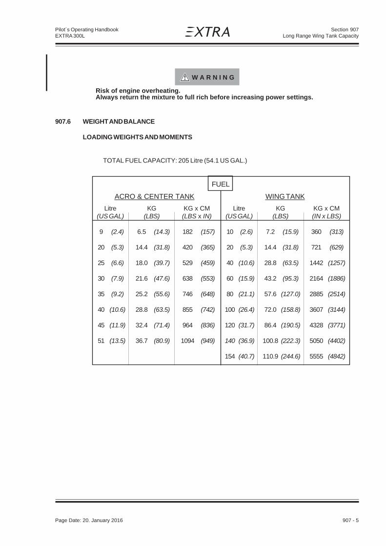
Section 907Long Range Wing Tank Capacity
Page Date: 20. April 2002 907 - 5
Pilot´s Operating HandbookEXTRA 300L
W A R N I N G
Risk of engine overheating.Always return the mixture to full rich before increasing power settings.
907.6 WEIGHT AND BALANCE
LOADING WEIGHTS AND MOMENTS
TOTAL FUEL CAPACITY: 205 Litre (54.1 US GAL.)
FUEL
ACRO & CENTER TANK WING TANK
Litre KG KG x CM Litre KG KG x CM(US GAL) (LBS) (LBS x IN) (US GAL) (LBS) (IN x LBS)
9 (2.4) 6.5 (14.3) 182 (157) 10 (2.6) 7.2 (15.9) 360 (313)
20 (5.3) 14.4 (31.8) 420 (365) 20 (5.3) 14.4 (31.8) 721 (629)
25 (6.6) 18.0 (39.7) 529 (459) 40 (10.6) 28.8 (63.5) 1442 (1257)
30 (7.9) 21.6 (47.6) 638 (553) 60 (15.9) 43.2 (95.3) 2164 (1886)
35 (9.2) 25.2 (55.6) 746 (648) 80 (21.1) 57.6 (127.0) 2885 (2514)
40 (10.6) 28.8 (63.5) 855 (742) 100 (26.4) 72.0 (158.8) 3607 (3144)
45 (11.9) 32.4 (71.4) 964 (836) 120 (31.7) 86.4 (190.5) 4328 (3771)
51 (13.5) 36.7 (80.9) 1094 (949) 140 (36.9) 100.8 (222.3) 5050 (4402)
154 (40.7) 110.9 (244.6) 5555 (4842)
Page Date: 20. January 2016

Section 907Long Range Wing Tank Capacity
907 - 6 Page Date: 20. April 2002
Pilot´s Operating HandbookEXTRA 300L
907.7 DESCRIPTION OF THE SYSTEM
Wing tank:
The leading edge section of each wing in front of main spars forms an integral fuel tankproviding two interconnected tanks with 154 litres (40.7 US GAL.) total capacity. Each side ofthe wing has a 2" diameter filler cap for gravity refuelling. The long range tank has twocompartments in either wing which are separated by a slosh rib. Due to the interconnectionthe fuel level of the left and right integral tank will equalize during refuelling within reasonabletime. For max. fuel capacity, the first-filled side has to be filled once again!The wing tank can be completely emptied in flight.
907.8 HANDLING, SERVICING AND MAINTENANCE
Not affected.
Page Date: 16. March 2009

Section 908Airtow Hook
Page Date: 20. April 2002 908 - 1
Pilot´s Operating HandbookEXTRA 300L
SECTION 908
AIRTOW HOOK
Table of Contents
Paragraph PageSECTION 908 AIRTOW HOOK
908.1 GENERAL ....................................................................................................................... 908-3
908.2 LIMITATIONS .................................................................................................................. 908-3
908.3 EMERGENCY PROCEDURES ....................................................................................... 908-4
908.4 NORMAL PROCEDURES............................................................................................... 908-4
908.5 PERFORMANCE ............................................................................................................ 908-5
908.6 WEIGHT AND BALANCE ............................................................................................... 908-7
908.7 DESCRIPTION OF THE SYSTEM .................................................................................. 908-7
908.8 HANDLING, SERVICING AND MAINTENANCE ............................................................. 908-7

Section 908Airtow Hook
908 - 2 Page Date: 20. April 2002
Pilot´s Operating HandbookEXTRA 300L
Left blank intentionally

Section 908Airtow Hook
Page Date: 20. April 2002 908 - 3
Pilot´s Operating HandbookEXTRA 300L
908.1 GENERAL
The EXTRA 300/L can optionally be equipped with a "TOST" glider air-tow release Typ E 85.The release mechanism is mounted at the tail spring end and actuated from the cockpit by ayellow knob.
908.2 LIMITATIONS
The following combinations are certified:
Aircraft
a) Engine: AEIO 540-L1B5 or AEIO 540-L1B5DPropeller: MTV-14-B-C/C190-17Exhaust system: Typ Gomolzig EA 300-606000 or standard exhaust PC-63104 withsilencer: NSD GO3-606500
b) Engine: AEIO-580-B1APropeller: MTV-9-B-C/C 198-25 (restricted to max. 2600 RPM) or MTV-14-B-C/C190-17Exhaust system: Typ Gomolzig EA 300-606000
Air-tow release system according to replacement instruction: UA-300-4-95Air-tow release: "TOST, E 85"
Glider
MTOW of the glider: 765Kg (1687 lbs)
Max. air towing speed of the glider: 152 km/h or above
Air tow cable and breaking piece (weak links)
Length of the synthetic tow between 40 m (130 ft) and 60 m (195 ft)Ultimate load of the air-tow max. 850 kp (1875 lbs)If tows with higher ultimate load are used a breaking piece (weak links) of max. 850 kp(1875 lbs) must be interconnected.
For a safe air towing the following points must be observed:
N O T E*
2-seats only in case of an instruction flight!
1.) Maximum air-towing speed = maximum permissible air-towing speed of the glider.2.) The maximum permissible cylinder head temperature is 500°F (red line) for AEIO-540
and 465°F (red line) for AEIO-580.3.) Interior mirror mounted.
For the location of the yellow release knob the following placard has to be attached in thenear of the knob:
AIR TOW
Page Date: 20. January 2016

Section 908Airtow Hook
908 - 4 Page Date: 20. April 2002
Pilot´s Operating HandbookEXTRA 300L
908.3 EMERGENCY PROCEDURES
A) ABORTED TAKE OFF
1. Pilot of the glider INFORM2. Throttle IDLE3. Mixture IDLE CUT OF4. Brakes APPLY AS PRACTICAL
B) ENGINE FAILURE IMMEDIATELY AFTER TAKEOFF
Stall speed: 60 KIAS (111 km/h)
1. Pilot of the glider INFORM2. Air tow RELEASE3. Airspeed 80 KIAS (148 km/h)4. Mixture IDLE CUT OFF5. Fuel shutoff valve OFF6. Ignition switch OFF7. Master switch OFF8. Forced landing PERFORM AS PRACTICAL
C) EXCESSIVE "CLIMB OVER" BY THE TOWING GLIDER
1. Pilot of the glider INFORM2. Air tow RELEASE3. Landing PERFORM AS PRACTICAL
D) TOW BREAK
1. Pilot of the glider INFORM2. Landing PERFORM AS PRACTICAL
908.4 NORMAL PROCEDURES
Preflight inspection, starting procedures, take-off procedure and the following climbing flighthave to be carry out in accordance with Chapter 4 "Normal procedure". In addition to thisprocedures the following points have to be observed:
A) PRIOR TO THE TAKE OFF
A release test needs to be conducted to determine safe release operation. The test shall bemade on both, aircraft and glider.
B) TAKE OFF
After air-tow hook up the tow shall be tighened gently. During the following take-off andclimb the maximum air-tow speed of the glider must be observed.
C) CLIMB
While climbing the max C.H.T. must be observed. Towing light gliders, the intial climb anglemay be very step. Information of the glider pilot is recomended.
D) RELEASE
After the release of the glider a gently left handed descent shall be flown to avoid collision ofglider and air-tow.
Page Date: 16. March 2009

Section 908Airtow Hook
Page Date: 20. April 2002 908 - 5
Pilot´s Operating HandbookEXTRA 300L
E) DESCENT AND LANDINGWhile descending the engine temperatures shall be observed (Avoid overcooling). Finalapproach should account for the air-tow hanging below the aircraft flight path.
908.5 PERFORMANCE
The existing POH-Data remain valid with the exception of:
TAKE-OFF DISTANCE
Conditions:
Power: 2600 Rpm or above and full throttle, mixture rich,short grass, dry and paved level runway, no wind,takeoff weight of the towing aircraft: 820Kg (1808lbs)
Liftoff speed (T/O): 65 KIAS = 120 Km/h indicatedObstacle clearance speed over 15m (50ft) : 70 KIAS = 130 Km/h indicated
For every 5 kts (9 km/h) headwind, the takeoff (T/O) distance can be decreased by 5%. Forevery 2 kts (4 km/h) tailwind [up to 10 kts (19 km/h)], the (T/O) distance is increased by 10%.
N O T E
All values are valid for single-pilot air-towing operation [820kg (1808 lbs) TOW]. Incase of an instruction flight with copilot, the higher takeoff weight has to beconsidered!
N O T E
The maximum permissible air-towing speed of the glider needs to be observed!
Page Date: 20. January 2016
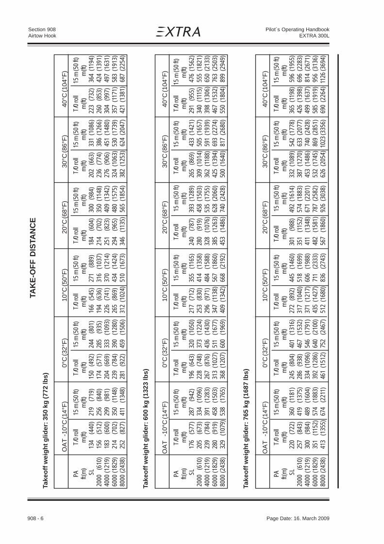
Section 908Airtow Hook
908 - 6 Page Date: 20. April 2002
Pilot´s Operating HandbookEXTRA 300L
TAK
E-O
FF
DIS
TAN
CE
Page Date: 16. March 2009
Tak
eo
ff w
eig
ht
gli
de
r: 3
50
kg
(7
72
lbs
)
O
AT
-10°
C (1
4°F
)0°
C (3
2°F
)10
°C (5
0°F
)20
°C (6
8°F
)30
°C (8
6°F
)40
°C (1
04°F
)
PAT/
0 ro
ll15
m (5
0 ft)
T/0
roll
15 m
(50
ft)T/
0 ro
ll15
m (5
0 ft)
T/0
roll
15 m
(50
ft)T/
0 ro
ll15
m (5
0 ft)
T/0
roll
15 m
(50
ft)ft (
m)
m (ft
)m
(ft)
m (ft
)m
(ft)
m (ft
)m
(ft)
m (ft
) m
(ft)
m (ft
)m
(ft)
m (ft
)m
(ft)
SL13
4(4
40)
219
(719
)15
0(4
92)
244
(801
)16
6(5
45)
271
(889
)18
4(6
04)
300
(984
)20
2(6
63)
331
(108
6)22
3(7
32)
364
(119
4)20
00
(610
)15
6(5
12)
256
(840
)17
4(5
71)
285
(935
)19
4(6
36)
316
(103
7)21
4(7
02)
350
(114
8)23
6(7
74)
386
(126
6)26
0(8
53)
424
(139
1)40
00 (1
219)
183
(600
)29
9(9
81)
204
(669
)33
3(1
093)
226
(741
)37
0(1
214)
251
(823
)40
9(1
342)
276
(906
)45
1(1
480)
304
(997
)49
7(1
631)
6000
(182
9)21
4(7
02)
350
(114
8)23
9(7
84)
390
(128
0)26
5(8
69)
434
(142
4)29
4(9
65)
480
(157
5)32
4(1
063)
530
(173
9)35
7(1
171)
583
(191
3)80
00 (2
438)
252
(827
)41
1(1
348)
281
(922
)45
9(1
506)
312
(102
4)51
0(1
673)
346
(113
5)56
5(1
854)
382
(125
3)62
4(2
047)
421
(138
1)68
7(2
254)
Tak
eo
ff w
eig
ht
gli
de
r: 6
00
kg
(1
32
3 lb
s)
O
AT
-10°
C (1
4°F
)0°
C (3
2°F
)10
°C (5
0°F
)20
°C (6
8°F
)30
°C (8
6°F
)40
°C (1
04°F
)
PAT/
0 ro
ll15
m (5
0 ft)
T/0
roll
15 m
(50
ft)T/
0 ro
ll 1
5 m
(50
ft)T/
0 ro
ll 1
5 m
(50
ft)T/
0 ro
ll 1
5 m
(50
ft)T/
0 ro
ll 1
5 m
(50
ft)ft (
m)
m (ft
)m
(ft)
m (ft
)m
(ft)
m (ft
)m
(ft)
m (ft
) m
(ft)
m (ft
)m
(ft)
m (ft
)m
(ft)
SL17
6(5
77)
287
(942
)19
6(6
43)
320
(105
0)21
7(7
12)
355
(116
5)24
0(7
87)
393
(128
9)26
5(8
69)
433
(142
1)29
1(9
55)
476
(156
2)20
00
(610
)20
5(6
73)
334
(109
6)22
8(7
48)
373
(122
4)25
3(8
30)
414
(135
8)28
0(9
19)
458
(150
3)30
9(1
014)
505
(165
7)34
0(1
115)
555
(182
1)40
00 (1
219)
239
(784
)39
1(1
283)
267
(876
)43
6(1
430)
296
(971
)48
4(1
588)
328
(107
6)53
5(1
755)
362
(118
8)59
1(1
939)
398
(130
6)65
0(2
133)
6000
(182
9)28
0(9
19)
458
(150
3)31
3(1
027)
511
(167
7)34
7(1
138)
567
(186
0)38
5(1
263)
628
(206
0)42
5(1
394)
693
(227
4)46
7(1
532)
763
(250
3)80
00 (2
438)
329
(107
9)53
8(1
765)
368
(120
7)60
0(1
969)
409
(134
2)66
8(2
192)
453
(148
6)74
0(2
428)
500
(164
0)81
7(2
680)
550
(180
4)89
9(2
949)
Tak
eo
ff w
eig
ht
gli
de
r: 7
65
kg
(1
68
7 lb
s)
O
AT
-10°
C (1
4°F
)0°
C (3
2°F
)10
°C (5
0°F
)20
°C (6
8°F
)30
°C (8
6°F
)40
°C (1
04°F
)
PAT/
0 ro
ll15
m (5
0 ft)
T/0
roll
15 m
(50
ft)T/
0 ro
ll 1
5 m
(50
ft)T/
0 ro
ll 1
5 m
(50
ft)T/
0 ro
ll 1
5 m
(50
ft)T/
0 ro
ll 1
5 m
(50
ft)ft (
m)
m (ft
)m
(ft)
m (ft
)m
(ft)
m (ft
)m
(ft)
m (ft
) m
(ft)
m (ft
)m
(ft)
m (ft
)m
(ft)
SL22
0(7
22)
360
(118
1)24
5(8
04)
401
(131
6)27
2(8
92)
445
(146
0)30
1(9
88)
492
(161
4)33
2(1
089)
542
(177
8)36
5(1
198)
596
(195
5)20
00
(610
)25
7(8
43)
419
(137
5)28
6(9
38)
467
(153
2)31
7(1
040)
518
(169
9)35
1(1
152)
574
(188
3)38
7(1
270)
633
(207
7)42
6(1
398)
696
(228
3)40
00 (1
219)
300
(984
)48
9(1
604)
334
(109
6)54
6(1
791)
371
(121
7)60
6(1
988)
411
(134
8)67
1(2
201)
453
(148
6)74
0(2
428)
499
(163
7)81
4(2
671)
6000
(182
9)35
1(1
152)
574
(188
3)39
2(1
286)
640
(210
0)43
5(1
427)
711
(233
3)48
2(1
581)
787
(258
2)53
2(1
745)
869
(285
1)58
5(1
919)
956
(313
6)80
00 (2
438)
413
(135
5)67
4(2
211)
461
(151
2)75
2(2
467)
512
(168
0)83
6(2
743)
567
(186
0)92
6(3
038)
626
(205
4)10
23(3
356)
690
(226
4)11
26(3
694)

Section 908Airtow Hook
Page Date: 20. April 2002 908 - 7
Pilot´s Operating HandbookEXTRA 300L
CLIMBRATE
Conditions:
Power: 2500 Rpm and full throttle, mixture rich,Speed of the aircraft tow: 76 KIAS = 140 Km/h,Weight of the towing aircraft: m = 820 Kg (1808 lb), (1 Pilot = 86 kg, Acro & Center Tankfull 38 L, Wingtank 30 L)
Tow force: glider with m = 350 kg (772 lbs)
PA 0°C (32°F) OAT 10°C (50°F) 20°C (68°F) 30°C (86°F)
ft (m) ft/min m/s ft/min m/s ft/min m/s ft/min m/s
• _ _SL 1610 8.2 1540 7.8 1480 7.5 1410 7.21000 (305) 1540 7.8 1475 7.5 1410 7.2 1345 6.82000 (610) 1475 7.5 1400 7.1 1340 6.8 1275 6.53000 (914) 1400 7.1 1335 6.8 1270 6.4 1210 6.14000 (1219) 1330 6.8 1265 6.4 1200 6.1 1140 5.85000 (1524) 1260 6.4 1195 6.1 1130 5.7 1070 5.46000 (1829) 1190 6.0 1130 5.7 1065 5.4 1000 5.17000 (2134) 1120 5.7 1060 5.4 995 5.1 935 4.78000 (2438) 1050 5.3 990 5.0 925 4.7 865 4.4
Tow force: glider with m = 600 kg (1323 lbs)
PA 0°C (32°F) OAT 10°C (50°F) 20°C (68°F) 30°C (86°F)
ft (m) ft/min m/s ft/min m/s ft/min m/s ft/min m/s
___SL 1280 6.5 1210 6.1 1150 5.8 1080 5.51000 (305) 1210 6.1 1145 5.8 1080 5.5 1015 5.22000 (610) 1140 5.8 1080 5.5 1010 5.1 950 4.83000 (914) 1080 5.5 1005 5.1 940 4.8 880 4.54000 (1219) 1005 5.1 935 4.7 870 4.4 810 4.15000 (1524) 935 4.7 870 4.4 800 4.1 740 3.86000 (1829) 865 4.4 800 4.1 735 3.7 675 3.47000 (2134) 800 4.1 730 3.7 670 3.4 605 3.18000 (2438) 730 3.7 670 3.4 600 3.0 545 2.8
Tow force: glider with m = 765 kg (1687 lbs)
PA 0°C (32°F) OAT 10°C (50°F) 20°C (68°F) 30°C (86°F)
ft (m) ft/min m/s ft/min m/s ft/min m/s ft/min m/s
___SL 920 4.7 850 4.3 785 4.0 725 3.71000 (305) 850 4.3 780 4.0 720 3.7 655 3.32000 (610) 780 4.0 715 3.6 650 3.3 585 3.03000 (914) 710 3.6 645 3.3 580 2.9 515 2.64000 (1219) 645 3.3 575 2.9 510 2.6 450 2.35000 (1524) 575 2.9 505 2.6 445 2.3 380 1.96000 (1829) 505 2.6 440 2.2 375 1.9 310 1.67000 (2134) 435 2.2 370 1.9 305 1.5 240 1.28000 (2438) 365 1.9 300 1.5 235 1.2 180 0.9
_
Page Date: 16. March 2009

Section 908Airtow Hook
908 - 8 Page Date: 20. April 2002
Pilot´s Operating HandbookEXTRA 300L
908.6 WEIGHT AND BALANCE
Not affected.
908.7 DESCRIPTION OF THE SYSTEM
The release mechanism is a typ "E 85" of the "TOST" company, Munich. It is mounted at thetail spring rear end aft the tail wheel and activated with a yellow handle located at the rearseat cockpit via a bowden cable.
908.8 HANDLING, SERVICING AND MAINTENANCE
Service and maintenance needs to be conducted in accordance with the latest operationhandbook (Typ E 85) of the manufacturer TOST GmbH, Germany. Additionally during the100 h inspection the bowden cable and the release handle have to be checked.
Page Date: 16. March 2009
Section 909Smoke System
Page Date: 20. April 2002 909 - 1
Pilot´s Operating HandbookEXTRA 300L
SECTION 909
SMOKE SYSTEM
Table of Contents
Paragraph PageSECTION 909 SMOKE SYSTEM
909.1 GENERAL.........................................................................................................................909.3
909.2 LIMITATIONS ...................................................................................................................909.3
909.3 EMERGENCY PROCEDURES...........................................................................................909.4
909.4 NORMAL PROCEDURES .................................................................................................909.4
909.5 PERFORMANCE ..............................................................................................................909.5
909.6 WEIGHT AND BALANCE .................................................................................................909.5
909.7 DESCRIPTION OF THE SYSTEM ....................................................................................909.6
909.8 HANDLING, SERVICING AND MAINTENANCE ................................................................909.7
Page Date: 20. January 2016

Section 909Smoke System
909 - 2 Page Date: 20. April 2002
Pilot´s Operating HandbookEXTRA 300L
Left blank intentionally

Section 909Smoke System
Page Date: 20. April 2002 909 - 3
Pilot´s Operating HandbookEXTRA 300L
909 SMOKE SYSTEM
909.1 GENERAL
For performing at airshows, the EXTRA 300L may optionally be equipped with a smokesystem.
909.2 LIMITATIONS
For safe operation of the smoke system the following limitations have to be considered:
1) The load factor and "MTOW" are limited to:
+8g/-8g at 870kg (ACRO II, limited to single seat operation), and
+6g/-6g at 950kg (ACRO III)
2) Specification of the smoke oil: straight paraffin oil, viscosity 30-50 cSt at 20°C (68°F),initial boiling point >330°C (626°F)For example: Fauth FC05, Texaco Canopus 13 or equivalent
3) Local airfield and weather conditions have to be considered:For the prevention of a fire alarm, inform the flight control before you activate thesmoke system
4) Recommended Manifold pressure: min. 20" Hg5) The activation of the smoke system on ground is only allowable for a brief system
test.
6) The operation of the smoke system is not allowable for the standard exhaust
(6 into 2) PC-63104 with mounted, external silencer NSD GO3-606500
7) Wearing a parachute is strongly recommended.
Operating Markings & Placards:
Page Date: 20. January 2016
On switch ofthe throttlelever
ON
OFF
External: Next to the quickconnector at the fuselage bottom
SMOKE-OIL(straight paraffin oil)40cSt, 31L, 8.2 USG
ON ONOn instrument panelabove control switch row
For SINGLE PUMP SYSTEM:On instrument panelabove circuit breaker row.
SMOKESYSTEM
SMOKE SMOKEPUMPS CONTROL
For DUAL PUMP SYSTEM:On instrument panelabove circuit breaker row.
OFF OFF
SMOKE SMOKEARM REFILL
On instrument panelbelow control switch row
BREAKEROn instrument panelbelow circuit breaker row

Section 909Smoke System
909 - 4 Page Date: 20. April 2002
Pilot´s Operating HandbookEXTRA 300L
909.3 EMERGENCY PROCEDURES
FAILURE OF THE SMOKE-SYSTEM
1. Switch "SMOKE ARM" and "SMOKE REFILL": OFF2. Circuit breaker PULL
FIRE IN FLIGHT
1. Switch "SMOKE ARM" OFF
If the fire (after the smoke system is shut off) will not extinguish proceed as follows:
2. Mixture IDLE CUT OFF3. Fuel selector valve OFF (Pull & Turn)4. Master switch OFF5. Airspeed 100 KIAS (185 km/h)
find your airspeed/attitude thatwill keep the fire away from the cockpit
6. Land AS SOON AS POSSIBLE7. If fire persists or aircraft is uncontrollable
and wearing a parachute BAIL OUT
SMOKE IN THE COCKPIT
1. Switch "SMOKE ARM" OFF2. Bad weather window OPEN3. Ventilation OPEN4. If smoke persists in the cockpit, land AS SOON AS PRACTICAL
909.4 NORMAL PROCEDURES
The smoke system includes features for refilling the smoke tanks and smoke generation:
A) REFILL
A separate refill hose is delivered with the smoke system which has to be used for filling thesmoke oil tanks from the paraffin oil supply cansister or barrel.
1. Refill hose CONNECT hose nipple to quickconnector at the fuselage bottom;IMMERSE the other end into the paraffinoil in the canister/barrel
2. Switch "SMOKE REFILL" ON
N O T E
The refilling should start within max. 30 sec. If this is not the case, the refill lines,fittings and filter (if installed) have to be checked for soiling or leaks. Refillingprocedure can be supported by reducing the suction height e.g. lifting the canister.The fully filled status is sensed by the floating device which automatically switchesthe refilling off.
Page Date: 20. January 2016

Section 909Smoke System
Page Date: 20. April 2002 909 - 5
Pilot´s Operating HandbookEXTRA 300L
yticapaC ssaM tnemoM
ertiL lagSU gK sbl mcgK sbl-ni
5 3.1 3.4 4.9 911 301
01 7.2 5.8 7.81 412 681
51 4 8.21 1.82 763 913
02 3.5 71 5.73 594 034
52 6.6 3.12 9.64 226 145
13 2.8 4.62 2.85 577 476
After automatic refill shut-off :
3. Switch "SMOKE REFILL" OFF4. Refill hose DISCONNECT
N O T E
A shut-off failure of the refill process can be recognized by smoke oil spilling out ofthe vent line. In this case, turn off refill switch. The floating device switch in the mainsmoke oil tank has to be checked accordingly.
B) SMOKE GENERATION
1. Bad weather window and ventilation CLOSE2. "SMOKE ARM" Switch ON3. Manifold Pressure minimum 20" Hg4. Switch in the throttle lever
for smoke generation ON - OFF
C A U T I O N
Smoke might enter the cockpit via the air vents during reverse maneuvers (forexample tail slide).It is recommended to operate the smoke system only in forward flight.
909.5 PERFORMANCE
Not affected.
909.6 WEIGHT AND BALANCE
Specific Weight of the paraffin oil = 0.85 kg/Litre
N O T E
The smoke system does not feature a capacity dipstick. In the case of unknownfilling, the smoke oil tanks should be drained and refilled with a known quantity. Ifthis is not possible, the most adverse case has to be taken for CG calculation. (Thismay be either completely full or completely empty tanks).
Page Date: 20. January 2016

Section 909Smoke System
909 - 6 Page Date: 20. April 2002
Pilot´s Operating HandbookEXTRA 300L
909.7 DESCRIPTION OF THE SYSTEM
On pilot's demand the smoke system produces a trail of smoke by injection of smoke oil (straightparaffin oil) into the engine exhaust. The smoke oil is vaporised by the exhaust gas heat and isvisible as dense smoke after leaving the exhaust.For smoke system activation the "SMOKE ARM" switch located on the pilot instrument panelneeds to be switched ON first. The smoke „ON-OFF“ toggle switch is located on top of thethrottle lever. For filling the smoke oil tanks the "SMOKE REFILL" switch needs to be ON. Afterthe refill process is completed the "SMOKE REFILL" has to switched OFF. When both switches("SMOKE ARM" and "SMOKE REFILL") are in the ON position, the smoke system is notenergized and will not run. There are two different systems approved:
A) DUAL PUMP SYSTEMThe main smoke oil tank is filled by a refill pump through a quick connector located in the aircraftbelly fairing. The separate floptube smoke oil tank is interconnected to the main smoke oil tankand gravity fed. Filled tanks are detected by a float switch placed in the main smoke oil tank whichshuts the refill pump off. An additional injection pump placed at the firewall within the enginecompartment pumps the smoke oil from the floptube smoke oil tank through a solenoid valveand the injector nozzle into the hot exhaust gas to generate smoke.
The system consists of:- Main smoke oil tank with float switch- Floptube smoke oil tank- Refill pump in the pilot compartment with quick connector in the belly fairing- Injection pump in the engine compartment with a shut-off solenoid in the pilot
compartment- ON-OFF switch on the throttle lever- Two relais (make contact type) for pumps and for the solenoid control- "SMOKE ARM" switch to arm the system and "SMOKE REFILL" switch for refilling
placed at the instrument-panel- Circuit breaker for pumps and control placed at the instrument-panel
B) SINGLE PUMP SYSTEMA pump (reversed polarity) fills the floptube smoke oil tank through a quick connector locatedin the aircraft belly fairing. This line includes a filter to prevent dirt to enter the smoke system.The separate main smoke oil tank is finally filled through the interconnected floptube smoke oiltank. Filled tanks are detected by a float switch placed in the main smoke oil tank which shuts
CIRCUIT BREAKER
SWITCHON ON
OFF OFF
SMOKE SMOKEARM REFILL
SMOKE SMOKECTRL SYS PUMPS
BREAKER
510 or 15
SMOKE SMOKEPUMPS CONTROL
OFF OFF
SMOKE SMOKEARM REFILL
Page Date: 20. January 2016

Section 909Smoke System
Page Date: 20. April 2002 909 - 7
Pilot´s Operating HandbookEXTRA 300L
the pump off. The same pump (normal polarity) injects the smoke oil from the floptube smoke oiltank through an overpressure/check valve and the injector nozzle into the hot exhaust gas togenerate smoke.
The system consists of:- Main smoke oil tank with float switch- Floptube smoke oil tank- Refill/Injection pump in the pilot compartment with quick connector in the belly fairing- Overpressure/check valve in the smoke oil supply line to the nozzle- Filter element in the refill line- ON-OFF switch on the throttle lever- Two relais (changeover contact type) for pump control- "SMOKE ARM" switch to arm the system and "SMOKE REFILL" switch for refilling
placed at the instrument-panel- Only 1 circuit breaker for pump and control placed at the instrument-panel
909.8 HANDLING, SERVICING AND MAINTENANCE
At every refilling:
- Check automatic shut-off
Additionally during the 100h Check for the DUAL PUMP SYSTEM
- Check the system for leakage (lines, fittings, tanks)- Check the smoke oil tanks for proper attachment- Check the function of the solenoid valve- Clean the injector nozzle: if required, remove carbon debris
Additionally during the 100h Check for the SINGLE PUMP SYSTEM
- Check the system for leakage (lines, fittings, tanks)- Check the smoke oil tanks for proper attachment- Clean the overpressure/check valve: if required, remove oil residue- Clean the injector nozzle: if required, remove carbon debris- Clean the filter element
CIRCUIT BREAKER
SWITCHON ON
OFF OFF
SMOKE SMOKEARM REFILL
SMOKE SMOKECTRL SYS PUMPS
BREAKER
15
SMOKESYSTEM
OFF OFF
SMOKE SMOKEARM REFILL
Page Date: 20. January 2016

Section 909Smoke System
909 - 8 Page Date: 20. April 2002
Pilot´s Operating HandbookEXTRA 300L
After each flight with activated Smoke System
- Clean the aircraft belly fairing and the rudder cable from smoke oil contamination
N O T E
The rudder cables might suffer from increased wear, when they are covered withsmoke oil and dust.
Page Date: 20. January 2016

Section 910Acro III Category
Page Date: 20. April 2002 910 - 1
Pilot´s Operating HandbookEXTRA 300L
SECTION 910
ACRO III CATEGORY
Table of Contents
Paragraph PageSECTION 910 ACRO III CATEGORY
910.1 GENERAL ....................................................................................................................... 910-3
910.2 LIMITATIONS .................................................................................................................. 910-3
910.3 EMERGENCY PROCEDURES ....................................................................................... 910-4
910.4 NORMAL PROCEDURES............................................................................................... 910-4
910.5 PERFORMANCE ............................................................................................................ 910-5
910.6 WEIGHT AND BALANCE ............................................................................................... 910-6
910.7 DESCRIPTION AND OPERATION OF AIRCRAFT AND ITS SYSTEMS ........................ 910-8
910.8 HANDLING, SERVICING AND MAINTENANCE ............................................................. 910-8

Section 910Acro III Category
910 - 2 Page Date: 20. April 2002
Pilot´s Operating HandbookEXTRA 300L
Left blank intentionally

Section 910Acro III Category
Page Date: 20. April 2002 910 - 3
Pilot´s Operating HandbookEXTRA 300L
910 ACRO III CATEGORY
910.1 GENERAL
The EXTRA 300/L can be operated in an additional two seat Acro III category. This category isdefined by a MTOW of 950 kg (2095 lbs), a max. load factor of +6g/-6g, and a V
A of 158 KIAS
(293 km/h).
910.2 LIMITATIONS
AIRSPEED
Maneuver Speed (Acro III): VA
158 KIAS (293 km/h)
WEIGHT LIMITS
Max. allowed empty weight: 745 kg (1643 lbs)Max. allowed T/O weight: 950 kg (2095 lbs)
WEIGHT AND C.G. ENVELOPE
Weight: forward C.G. rear C.G.
MTOW 950 kg (2095 lbs) and below: 67,1 cm (26.4") 84,1 cm (33.1")
LOAD FACTOR
+6g / -6g for two seat occupied (MTOW 950 kg / 2095 lbs)
OPERATING PLACARDS
VA = 158 Kts (Acro I+II+III) or VA = 293 km/h (Acro I+II+III) (near airspeed indicator)VA = 140 Kts (Normal) VA = 259 km/h (Normal)
ACROBATIC:± 10 G, 1 PILOT, MTOW: 820 KG (1808 LBS)± 8 G, 2 PERSONS ON BOARD, MTOW: 870 KG (1918 LBS)± 6 G, 2 PERSONS ON BOARD, MTOW: 950 KG (2095 LBS)
NORMAL: + 6 G/ -3 G; MTOW: 950 KG (2095 LBS) (in both cockpits)ACROBATICS INCL. SPIN NOT APPROVED
Page Date: 16. March 2009

Section 910Acro III Category
910 - 4 Page Date: 20. April 2002
Pilot´s Operating HandbookEXTRA 300L
910.3 EMERGENCY PROCEDURES
Not affected
910.4 NORMAL PROCEDURES
AIRSPEEDS FOR NORMAL OPERATION
CATEGORY ACRO I ACRO II ACRO III NORMAL1 seat 2 seats 2 seats
KIAS (km/h) KIAS (km/h) KIAS (km/h) KIAS (km/h)
Start:-Rotating Speed 60 (111) 62 (115) 65 (120) 65 (120)
Climb:-Vx 87 (161) 89 (165) 93 (172) 93 (172)-Vy 96 (178) 99 (183) 104 (193) 104 (193)
-Recommended Normal-Climb Speed 100 (185) 105 (194) 110 (204) 110 (204)-Max. Cruise 185 (343) 185 (343) 185 (343) 185 (343)
Landing:-Approach 80 (148) 85 (157) 90 (167) 90 (167)-on Final 72 (133) 74 (137) 78 (144) 78 (144)-Go-Around Speed 90 (167) 95 (176) 100 (185) 100 (185)
Recommended AirspeedFor Flight In Rough Air (max.) VA 158 (293) 158 (293) 158 (293) 140 (259)
Max. Demonstrated CrossWind Component 15 kts (27) 15 kts (27) 15 kts (27) 15 kts (27)
Page Date: 16. March 2009
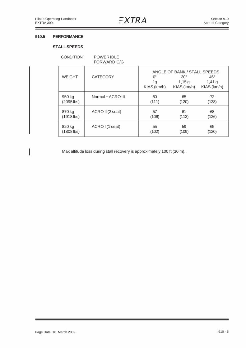
Section 910Acro III Category
Page Date: 20. April 2002 910 - 5
Pilot´s Operating HandbookEXTRA 300L
910.5 PERFORMANCE
STALL SPEEDS
CONDITION: POWER IDLEFORWARD C/G
ANGLE OF BANK / STALL SPEEDSWEIGHT CATEGORY 0° 30° 45°
1g 1,15 g 1,41 gKIAS (km/h) KIAS (km/h) KIAS (km/h)
950 kg Normal + ACRO III 60 65 72(2095 lbs) (111) (120) (133)
870 kg ACRO II (2 seat) 57 61 68(1918 lbs) (106) (113) (126)
820 kg ACRO I (1 seat) 55 59 65(1808 lbs) (102) (109) (120)
Max altitude loss during stall recovery is approximately 100 ft (30 m).
Page Date: 16. March 2009

Section 910Acro III Category
910 - 6 Page Date: 20. April 2002
Pilot´s Operating HandbookEXTRA 300L
CE
NT
ER
OF
GR
AV
TIT
Y C
AL
CU
LA
TIO
N (S
AM
PL
E P
RO
BL
EM
)
910.6 WEIGHT AND BALANCE

Section 910Acro III Category
Page Date: 20. April 2002 910 - 7
Pilot´s Operating HandbookEXTRA 300L
EXAMPLE:At 790 KG (1741 LBS) and 640000 kgcm theC/G location is 80,0 cm (31,4") aft of ref datum
WEIGHT AND MOMENT LIMITS

Section 910Acro III Category
910 - 8 Page Date: 20. April 2002
Pilot´s Operating HandbookEXTRA 300L
910.7 DESCRIPTION AND OPERATION OF AIRCRAFT AND ITS SYSTEMS
Not affected.
910.8 HANDLING, SERVICING AND MAINTENANCE
Not affected.

Section 911Single Seat Canopy
Page Date: 20. April 2002 911 - 1
Pilot´s Operating HandbookEXTRA 300L
SECTION 911
SINGLE SEAT CANOPY
Table of Contents
Paragraph PageSECTION 911 SINGLE SEAT CANOPY
911.1 GENERAL ....................................................................................................................... 911-3
911.2 LIMITATIONS .................................................................................................................. 911-3
911.3 EMERGENCY PROCEDURES ....................................................................................... 911-3
911.4 NORMAL PROCEDURES............................................................................................... 911-3
911.5 PERFORMANCE ............................................................................................................ 911-3
911.6 WEIGHT AND BALANCE AND EQUIPMENT LIST ........................................................ 911-3
911.7 DESCRIPTION OF THE SYSTEM .................................................................................. 911-3
911.8 HANDLING, SERVICE AND MAINTENANCE ........................................................................ 3

Section 911Single Seat Canopy
911 - 2 Page Date: 20. April 2002
Pilot´s Operating HandbookEXTRA 300L
Left blank intentionally

Section 911Single Seat Canopy
Page Date: 20. April 2002 911 - 3
Pilot´s Operating HandbookEXTRA 300L
911 SINGLE SEAT CANOPY
911.1 GENERAL
For airshow performances the standard canopy can be replaced by a single seat canopy,which gives a gorgeous appearance.
911.2 LIMITATIONS
With the single seat canopy installed the aircraft is limited to the categories
NORMAL and ACRO I.
In the NORMAL category the aircraft can be flown only with the pilot in the rear seat.
911.3 EMERGENCY PROCEDURES
Not affected.
911.4 NORMAL PROCEDURES
Befor starting engine, check front seat area and ensure seat belts and shoulder harness offront seat are completely removed or fastened and secured, so that nothing can obstruct thefree movement of controls.
911.5 PERFORMANCE
Not affected.
911.6 WEIGHT AND BALANCE AND EQUIPMENT LIST
Refer to the equipment list in section 6.
911.7 DESCRIPTION OF THE SYSTEM
The single seat canopy has been designed to easily replace the standard canopy. This can beachieved by using the same canopy frame, hinges and latches included. The front seat iscovered by the flat portion of the frame in front of the canopy. Operation of the lockingmechanism is feasible only from the rear seat.
911.8 HANDLING, SERVICE AND MAINTENANCE
Not affected.
Page Date: 31. March 2009

Section 911Single Seat Canopy
911 - 4 Page Date: 20. April 2002
Pilot´s Operating HandbookEXTRA 300L
Left blank intentionally

Section 912FILSER TRT 600 Transponder
Page Date: 15. December 2005 912 - 1
Pilot´s Operating HandbookEXTRA 300L
SECTION 912
FILSER TRT 600 TRANSPONDER
Table of Contents
Paragraph PageSECTION 912 FILSER TRT 600 TRANSPONDER
912.1 GENERAL ....................................................................................................................... 912-3912.1.1 Front Panel Operation ..................................................................................................... 912-3912.1.2 System Operation ............................................................................................................ 912-5912.1.3 Error Reporting / Fault Codes .......................................................................................... 912-7
912.2 LIMITATIONS .................................................................................................................. 912-8
912.3 EMERGENCY PROCEDURES ....................................................................................... 912-8
912.4 NORMAL PROCEDURES............................................................................................... 912-8
912.5 PERFORMANCE ............................................................................................................ 912-8

Section 912FILSER TRT 600 Transponder
912 - 2 Page Date: 15. December 2005
Pilot´s Operating HandbookEXTRA 300L
Left blank intentionally

Section 912FILSER TRT 600 Transponder
Page Date: 15. December 2005 912 - 3
Pilot´s Operating HandbookEXTRA 300L
912.1 GENERAL
The TRT 600 is Level 2es Class2 (SSR Mode S Elementary Surveillance) Transponder. It has ModeA, Mode A/C and Mode S capability. In Mode S the transponder provides acquisition capability.Furthermore, the TRT 600 has a built-in barometric pressure altitude coder in 100 ft increments.
NOTE
Refer to latest edition of Filser TRT 600 Pilot's Operation Manual (Doc. No. 03.200.010.11)to get familiar with the TRT 600 Transponder.
The following illustration of the front panel of the TRT 600 will assist the operator to understandthis Mode S Transponder.
912.1.1 FRONT PANEL OPERATION
The input elements consist of four rotating knobs and five push buttons.

Section 912FILSER TRT 600 Transponder
912 - 4 Page Date: 15. December 2005
Pilot´s Operating HandbookEXTRA 300L
ROTATING KNOBS
Four rotating knobs are used to select the IDENT CODE.
The assignments X… , .X.. , ..X. , …X indicate the position of the code number set by each knob.
PUSH BUTTONS
ON OFFThe unit can be turned on by pressing the ON OFF button for less then 1 second.The unit can be turned off by pressing the ON OFF button for more then 2 seconds.(also refer to the System Operation Paragraph 912.1.2).
MODEThe following modes can be selected in sequence by pressing the MODE button:
STBY Standby Mode used for aircraft on ground with reduced squitter rate, only Mode S withaltitude reporting all ZERO only
A-S Mode A active with Mode C frames only and Mode S with altitude reporting all ZEROonly
ACS Mode A ,C and S full active
ARROWS UP AND DOWNTo activate the inserted SQUAWK CODE from the lower standby line to the upper active positionthe button with the UP AND DOWN ARROWS shall be pressed.
IDENTThe IDENT push button causes the special position identification pulse (SPI) to be transmittedfor a period of 18 seconds.
FIDIn the Standby Mode, the Aircraft Identification (Flight Identification) and Aircraft Address can bechecked by pressing the push button FID. The Flight Identification is displayed on the right sideof the lower line. By pressing the button FID for more than 3 seconds the input mode can be setor the Flight Identification can be changed.
FLAGS
Squitter FlagWhen the extended squitter is active the letter 'S' is displayed on the left top side of the display.As the squitter is a periodic signal, the displayed 'S' is blinking.
Reply FlagIn case of the transponder replying to interrogations the letter 'R' is displayed on the left top sideof the display.

Section 912FILSER TRT 600 Transponder
Page Date: 15. December 2005 912 - 5
Pilot´s Operating HandbookEXTRA 300L
In-Flight FlagWhen there is an undercarriage switch installed, the display can toggle between the letters 'F'whether the aircraft is in flight condition or the letter 'G' whether the aircraft is in „on-ground“condition. The flag is displayed on the right bottom side of the display.
Battery FlagIf the power supply to the transponder drops below 10 Volts, the flag 'BAT' appears and startsflashing.
912.1.2 SYSTEM OPERATION
The transponder should be turned off before starting and shutting down aircraft engines.
ON /OFFAfter having switched on the AVIONIC MASTER switch the TRT 600 has to be turned on by handby pressing the ON OFF button for less then 1 second. The display will first show the transpondertype and the software and firmware version. To turn off the unit the button ON/OFF must bepressed for more then two seconds or the AVIONIC MASTER switch must be placed to the OFF-position. ACS is the default operation mode and the transponder replies to Mode A,C and Sinterrogations. The pressure altitude will be displayed as Flight Level.
SQUAWK SELECTION
Squawk selection is done with the four rotating knobs to provide 4096 identification codes. Theassignments of the knobs, starting at top left, are:
X… selection of thousands (0-7).X... selection of hundreds (0-7)..X. selection of ten (0-7)…X selection of one (0-7)
The code is entered in the lower line and remains inactive. By pushing the UP AND DOWNARROWS button the squawk code is transferred to the upper line and becomes active. The codein the upper line is always the active one.
IMPORTANT CODES:
1200 The VFR code for any altitude in the US (Refer to ICAO standards elsewhere)
7000 The VFR code commonly used in Europe (Refer to ICAO standards)
0021 The VFR code commonly used in Germany (default is set to 0021 at time ofinstallation)
7500 Hijack code (Aircraft is subject to unlawful interference)
7600 Loss of communications
7700 Emergency

Section 912FILSER TRT 600 Transponder
912 - 6 Page Date: 15. December 2005
Pilot´s Operating HandbookEXTRA 300L
7777 Military interceptor operations (Never squawk this code)
0000 Military use (Not enterable)
Care should be taken not to select the code 7500 and all codes in the 7600-7777 range, which triggerspecial indicators in automated facilities. Only the code 7500 will be decoded as the hijack code.An aircraft’s transponder code (if available) is utilized to enhance the tracking capabilities of theATC facility, therefore care should be taken when making routine code changes.
STANDBY MODE
The standby mode is activated by pressing the MODE button once. This sets 'STBY' in the modeindicator field. The transponder will now only reply to direct addressed Mode S interogations. Thesquitter stays active at a lower rate.
ALTITUDE OFF
Switching off altitude reporting will be necessary if the ATC controller requests it.For switching off altitude reporting the MODE button has to be pressed until 'A-S' is displayed.The altitude display shows 'FL ——' to indicate that the altitude reporting is not active. Now thetransponder will reply on Mode C interrogations with Mode C frames only and Mode Sinterrogations with FL000 (= 0000ft) instead of the actual altitude.
IDENT
Pressing the IDT push button causes the special position identification pulse (SPI) to be appendedto the Mode A replies for a period of 18 seconds and sets 'IDT' in the display.
LOW POWER SUPPLY
If the power supply to the transponder drops below 10 Volts, the flag 'BAT' appears and startsflashing.
DISPLAYING AIRCRAFT ADDRESS AND FLIGHT IDENTIFICATION
By pressing, the FID button for less than 3 seconds, while the unit is in Stanby-mode, the left sideof the bottom line will show the aircraft address.
N O T E
Only an authorized service station is allowed to enter or change the ICAO aircraft address.If you do not have the ICAO aircraft address. Please refer to your national aviation authorityto apply for your aircraft address.
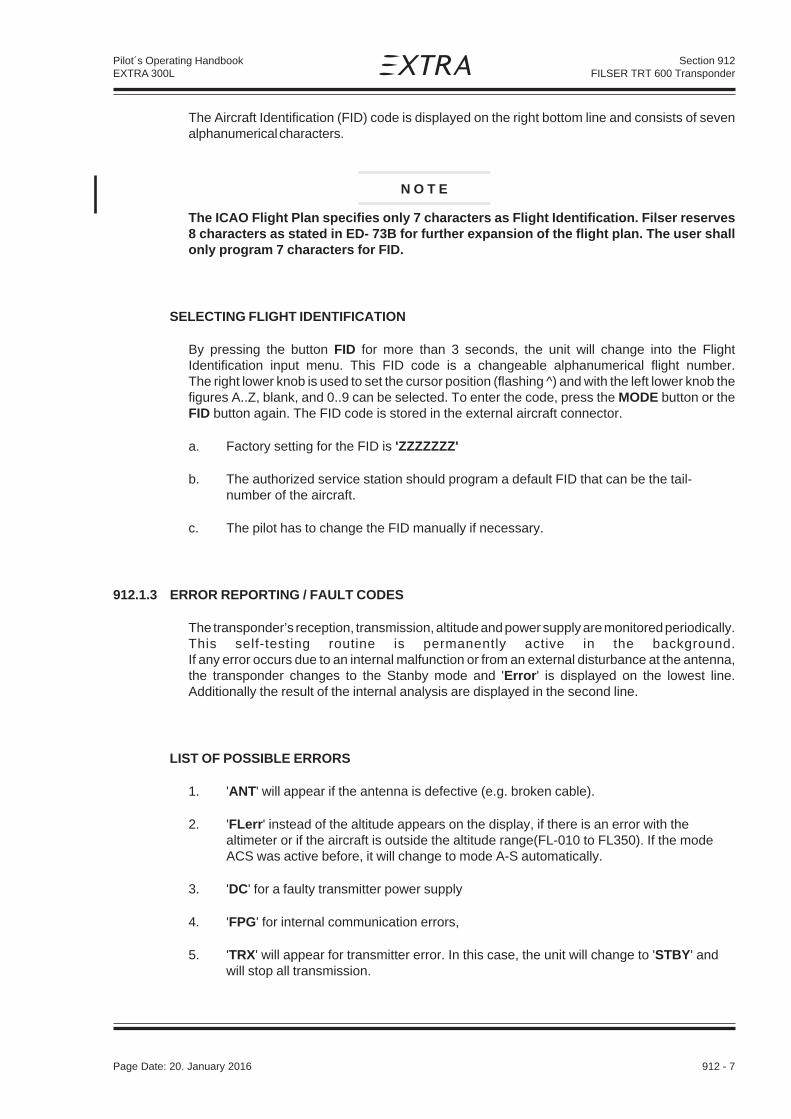
Section 912FILSER TRT 600 Transponder
Page Date: 15. December 2005 912 - 7
Pilot´s Operating HandbookEXTRA 300L
The Aircraft Identification (FID) code is displayed on the right bottom line and consists of sevenalphanumerical characters.
N O T E
The ICAO Flight Plan specifies only 7 characters as Flight Identification. Filser reserves8 characters as stated in ED- 73B for further expansion of the flight plan. The user shallonly program 7 characters for FID.
SELECTING FLIGHT IDENTIFICATION
By pressing the button FID for more than 3 seconds, the unit will change into the FlightIdentification input menu. This FID code is a changeable alphanumerical flight number.The right lower knob is used to set the cursor position (flashing ̂ ) and with the left lower knob thefigures A..Z, blank, and 0..9 can be selected. To enter the code, press the MODE button or theFID button again. The FID code is stored in the external aircraft connector.
a. Factory setting for the FID is 'ZZZZZZZ'
b. The authorized service station should program a default FID that can be the tail-number of the aircraft.
c. The pilot has to change the FID manually if necessary.
912.1.3 ERROR REPORTING / FAULT CODES
The transponder’s reception, transmission, altitude and power supply are monitored periodically.This self-testing routine is permanently active in the background.If any error occurs due to an internal malfunction or from an external disturbance at the antenna,the transponder changes to the Stanby mode and 'Error' is displayed on the lowest line.Additionally the result of the internal analysis are displayed in the second line.
LIST OF POSSIBLE ERRORS
1. 'ANT' will appear if the antenna is defective (e.g. broken cable).
2. 'FLerr' instead of the altitude appears on the display, if there is an error with thealtimeter or if the aircraft is outside the altitude range(FL-010 to FL350). If the modeACS was active before, it will change to mode A-S automatically.
3. 'DC' for a faulty transmitter power supply
4. 'FPG' for internal communication errors,
5. 'TRX' will appear for transmitter error. In this case, the unit will change to 'STBY' andwill stop all transmission.
Page Date: 20. January 2016

Section 912FILSER TRT 600 Transponder
912 - 8 Page Date: 15. December 2005
Pilot´s Operating HandbookEXTRA 300L
To meet ICAO specifications the TRT 600 uses an external memory inside the aircraft connectorhousing of the cable set, which is a part of the aircraft. Because this cable is installed permanentinto the aircraft, a change of the transponder will not affect the aircraft address and the Flight ID.In the event there is a Cradle error, (empty memory or data error) 'OUT OF ORDER' will bedisplayed .The first line shows which kind of error is present:
'Cradle OFF' displayed means no or defective data.'Cradle Data' displayed means digital checksum error.
After a few seconds the display shows normal operating condition but with inhibited Mode S. Thetransponder will work with Mode A/C only. You will need to consult an authorized service stationto enter the ICAO aircraft address (see TRT 600 Installation Manual). Please consult yourairworthiness authority for national procedures.
N O T E
If no valid ICAO 24 bit aircraft address is programmed to the unit or if the memory isinoperative the transponder will inhibit the Mode S functions. In this case only Mode A/Cfunction will be available.
912.2 LIMITATIONS
Not applicable
912.3 EMERGENCY PROCEDURES
The following emergency codes should be noted:
7500 Hijacking
7600 Loss of communication
7700 Emergency
912.4 NORMAL PROCEDURES
Not applicable
912.5 PERFORMANCE
Not applicable

Section 913FILSER TRT 800 Transponder
Page Date: 15. December 2005 913 - 1
Pilot´s Operating HandbookEXTRA 300L
SECTION 913
FILSER TRT 800 TRANSPONDER
Table of Contents
Paragraph PageSECTION 913 FILSER TRT 800 TRANSPONDER
913.1 GENERAL.........................................................................................................................913-3913.1.1 Front Panel Operation .......................................................................................................913-3913.1.2 System Operation ............................................................................................................. 913-5913.1.3 Error Reporting / Fault Codes ............................................................................................913-7
913.2 LIMITATIONS ...................................................................................................................913-8
913.3 EMERGENCY PROCEDURES...........................................................................................913-8
913.4 NORMAL PROCEDURES .................................................................................................913-8
913.5 PERFORMANCE ..............................................................................................................913-8

Section 913FILSER TRT 800 Transponder
913 - 2 Page Date: 15. December 2005
Pilot´s Operating HandbookEXTRA 300L
Left blank intentionally

Section 913FILSER TRT 800 Transponder
Page Date: 15. December 2005 913 - 3
Pilot´s Operating HandbookEXTRA 300L
913.1 GENERAL
The TRT 800 is Level 2es Class2 (SSR Mode S Elementary and Enhanced Surveillance)Transponder. It has Mode A, Mode A/C and Mode S capability. In Mode S the transponderprovides acquisition and extended squitter capability. Furthermore, the TRT 800 has a built-inbarometric pressure altitude coder in 100 ft increments.
N O T E
Refer to latest edition of Filser TRT 800 Pilot's Operation Manual (Doc. No. 03.210.010.11)to get familiar with the TRT 800 Transponder.
The following illustration of the front panel of the TRT 800 will assist the operator to understand thisMode S Transponder.
913.1.1 FRONT PANEL OPERATION
The input elements consist of four rotating knobs and five push buttons.

Section 913FILSER TRT 800 Transponder
913 - 4 Page Date: 15. December 2005
Pilot´s Operating HandbookEXTRA 300L
ROTATING KNOBS
Four rotating knobs are used to select the IDENT CODE.
The assignments X… , .X.. , ..X. , …X indicate the position of the code number set by each knob.
PUSH BUTTONS
ON OFFThe unit can be turned on by pressing the ON OFF button for less then 1 second. The unit canbe turned off by pressing the ON OFF button for more then 2 seconds. (also refer to the SystemOperation Paragraph 913.1.2)
MODEThe following modes can be selected in sequence by pressing the MODE button:
STBY Standby Mode used for aircraft on ground with reduced squitter rate, only Mode S withaltitude reporting all ZERO only
A-S Mode A active with Mode C frames only and Mode S with altitude reporting all ZEROonly
ACS Mode A ,C and S full active
ARROWS UP AND DOWNTo activate the inserted SQUAWK CODE from the lower standby line to the upper active positionthe button with the UP AND DOWN ARROWS shall be pressed.
IDENTThe IDENT push button causes the special position identification pulse (SPI) to be transmittedfor a period of 18 seconds.
FIDIn the Standby Mode, the Aircraft Identification (Flight Identification) and Aircraft Address can bechecked by pressing the push button FID. The Flight Identification is displayed on the right sideof the lower line. By pressing the button FID for more than 3 seconds the input mode can be setor the Flight Identification can be changed.
FLAGS
SQUITTER FLAGWhen the extended squitter is active the letter 'S' is displayed on the left top side of the display.As the squitter is a periodic signal, the displayed 'S' is blinking.
REPLY FLAGIn case of the transponder replying to interrogations the letter 'R' is displayed on the left top sideof the display.

Section 913FILSER TRT 800 Transponder
Page Date: 15. December 2005 913 - 5
Pilot´s Operating HandbookEXTRA 300L
IN-FLIGHT FLAGWhen there is an undercarriage switch installed, the display can toggle between the letters 'F'whether the aircraft is in flight condition or the letter 'G' whether the aircraft is in „on-ground“condition. The flag is displayed on the right bottom side of the display.
BATTERY FLAGIf the power supply to the transponder drops below 10 Volts, the flag 'BAT' appears and startsflashing.
913.1.2 SYSTEM OPERATION
The transponder should be turned off before starting and shutting down aircraft engines.
ON /OFFAfter having switched on the AVIONIC MASTER switch the TRT 800 has to be turned on by handby pressing the ON OFF button for less then 1 second. The display will first show the transpondertype and the software and firmware version. To turn off the unit the button ON/OFF must bepressed for more then two seconds or the AVIONIC MASTER switch must be placed to the OFFposition. ACS is the default operation mode and the transponder replies to Mode A,C and Sinterrogations. The pressure altitude will be displayed as Flight Level.
SQUAWK SELECTION
Squawk selection is done with the four rotating knobs to provide 4096 identification codes. Theassignments of the knobs, starting at top left, are:
X… selection of thousands (0-7).X... selection of hundreds (0-7)..X. selection of ten (0-7)…X selection of one (0-7)
The code is entered in the lower line and remains inactive. By pushing the UP AND DOWNARROWS button the squawk code is transferred to the upper line and becomes active. The codein the upper line is always the active one.
IMPORTANT CODES:
1200 The VFR code for any altitude in the US (Refer to ICAO standards elsewhere)
7000 The VFR code commonly used in Europe (Refer to ICAO standards)
0021 The VFR code commonly used in Germany (default is set to 0021 at time ofinstallation)
7500 Hijack code (Aircraft is subject to unlawful interference)
7600 Loss of communications

Section 913FILSER TRT 800 Transponder
913 - 6 Page Date: 15. December 2005
Pilot´s Operating HandbookEXTRA 300L
7700 Emergency
7777 Military interceptor operations (Never squawk this code)
0000 Military use (Not enterable)
Care should be taken not to select the code 7500 and all codes in the 7600-7777 range, which triggerspecial indicators in automated facilities. Only the code 7500 will be decoded as the hijack code.An aircraft’s transponder code (if available) is utilized to enhance the tracking capabilities of theATC facility, therefore care should be taken when making routine code changes.
STANDBY MODE
The standby mode is activated by pressing the MODE button once. This sets 'STBY' in the modeindicator field. The transponder will now only reply to direct addressed Mode S interogations. Thesquitter stays active at a lower rate.
ALTITUDE OFF
Switching off altitude reporting will be necessary if the ATC controller requests it.For switching off altitude reporting the MODE button has to be pressed until 'A-S' is displayed.The altitude display shows 'FL ——' to indicate that the altitude reporting is not active. Now thetransponder will reply on Mode C interrogations with Mode C frames only and Mode Sinterrogations with FL000 (= 0000ft) instead of the actual altitude.
IDENT
Pressing the IDT push button causes the special position identification pulse (SPI) to be appendedto the Mode A replies for a period of 18 seconds and sets 'IDT' in the display.
LOW POWER SUPPLY
If the power supply to the transponder drops below 10 Volts, the flag 'BAT' appears and startsflashing.
DISPLAYING AIRCRAFT ADDRESS AND FLIGHT IDENTIFICATION
By pressing, the FID button for less than 3 seconds, while the unit is in Stanby-Mode, the left sideof the bottom line will show the aircrafgt address.
N O T E
Only an authorized service station is allowed to enter or change the ICAO aircraft address.If you do not have the ICAO aircraft address. Please refer to your national aviation authorityto apply for your aircraft address.

Section 913FILSER TRT 800 Transponder
Page Date: 15. December 2005 913 - 7
Pilot´s Operating HandbookEXTRA 300L
The Aircraft Identification (FID) code is displayed on the right bottom line and consists of sevenalphanumerical characters.
N O T E
The ICAO Flight Plan specifies only 7 characters as Flight Identification. Filser reserves8 characters as stated in ED- 73B for further expansion of the flight plan. The user shallonly program 7 characters for FID.
SELECTING FLIGHT IDENTIFICATION
By pressing the button FID for more than 3 seconds, the unit will change into the FlightIdentification input menu. This FID code is a changeable alphanumerical flight number.The right lower knob is used to set the cursor position (flashing ̂ ) and with the left lower knob thefigures A..Z, blank, and 0..9 can be selected. To enter the code, press the MODE button or theFID button again. The FID code is stored in the external aircraft connector.
a. Factory setting for the FID is 'ZZZZZZZ'
b. The authorized service station should program a default FID that can be the tail-number of the aircraft.
c. The pilot has to change the FID manually if necessary.
913.1.3 ERROR REPORTING / FAULT CODES
The transponder’s reception, transmission, altitude and power supply are monitored periodically.This self-testing routine is permanently active in the background. If any error occurs due to aninternal malfunction or from an external disturbance at the antenna, the transponder changes tothe Standby Mode and „Error“ is displayed on the lowest line. Additionally the result of the internalanalysis are displayed in the second line.
LIST OF POSSIBLE ERRORS:
1. 'ANT' will appear if the antenna is defective (e.g. broken cable).
2. 'FLerr' instead of the altitude appears on the display, if there is an error with thealtimeter or if the aircraft is outside the altitude range(FL-010 to FL350). If the modeACS was active before, it will change to mode A-S automatically.
3. 'DC' for a faulty transmitter power supply
4. 'FPG' for internal communication errors,
5. 'TRX' will appear for transmitter error. In this case, the unit will change to 'STBY' and willstop all transmission.
Page Date: 20. January 2016

Section 913FILSER TRT 800 Transponder
913 - 8 Page Date: 15. December 2005
Pilot´s Operating HandbookEXTRA 300L
To meet ICAO specifications the TRT 800 uses an external memory inside the aircraft connectorhousing of the cable set, which is a part of the aircraft. Because this cable is installed permanentinto the aircraft, a change of the transponder will not affect the aircraft address and the Flight ID.In the event there is a Cradle error, (empty memory or data error) „OUT OF ORDER“ will bedisplayed .The first line shows which kind of error is present:
'Cradle OFF' displayed means no or defective data.'Cradle Data' displayed means digital checksum error.
After a few seconds the display shows normal operating condition but with inhibited Mode S. Thetransponder will work with Mode A/C only. You will need to consult an authorized service stationto enter the ICAO aircraft address (see TRT800 Installation Manual). Please consult yourairworthiness authority for national procedures.
N O T E
If no valid ICAO 24 bit aircraft address is programmed to the unit or if the memory isinoperative the transponder will inhibit the Mode S functions. In this case only Mode A/Cfunction will be available.
913.2 LIMITATIONS
Not applicable.
913.3 EMERGENCY PROCEDURES
The following emergency codes should be noted:
7500 Hijacking
7600 Loss of communication
7700 Emergency
913.4 NORMAL PROCEDURES
Not applicable.
913.5 PERFORMANCE
Not applicable.

Section 914GARMIN GTX 327 Transponder
Page Date: 15. December 2005 914 - 1
Pilot´s Operating HandbookEXTRA 300L
SECTION 914
GARMIN GTX 327 TRANSPONDER
Table of Contents
Paragraph PageSECTION 914 GARMIN GTX 327 TRANSPONDER
914.1 GENERAL ....................................................................................................................... 914-3914.1.1 Mode Selection Keys ....................................................................................................... 914-3914.1.2 Code Selection ................................................................................................................ 914-4914.1.3 Keys for other GTX 327 Functions .................................................................................. 914-4
914.2 LIMITATIONS .................................................................................................................. 914-5
914.3 EMERGENCY PROCEDURES ....................................................................................... 914-6914.3.1 Important Codes .............................................................................................................. 914-6
914.4 NORMAL PROCEDURES............................................................................................... 914-6
914.5 PERFORMANCE ............................................................................................................ 914-6

Section 914GARMIN GTX 327Transponder
914 - 2 Page Date: 15. December 2005
Pilot´s Operating HandbookEXTRA 300L
Left blank intentionally

Section 914GARMIN GTX 327 Transponder
Page Date: 15. December 2005 914 - 3
Pilot´s Operating HandbookEXTRA 300L
914.1 GENERAL
The GARMIN GTX 327 is a panel-mounted TSO.d transponder with the addition of timing functions.The transponder is a radio transmitter and receiver that operates on radar frequencies, receivingground radar interrogations at 1030 MHz and transmitting a coded response of pulses to ground-based radar on a frequency of 1090 MHz.
N O T E
The GTX 327 owner accepts all responsibility for obtaining the proper license before usingthe transponder.
The coverage you can expect from the GTX 327 is limited to „line of sight“. Low altitude or aircraftantenna shielding by the aircraft itself may result in reduced range. Range can be improved byclimbing to a higher altitude. It may be possible to minimize antenna shielding by locating theantenna where dead spots are only noticed during abnormal flight attitudes.
N O T I C E
Damage possible due to current peaks.The GTX 327 should be turned off before starting or shutting down aircraft engine.
The GTX 327 Transponder is powered on by pressing the STBY, ALT or ON keys, or by the AVIONICMASTER switch. After power on a start-up page will be displayed while the unit performs a self test.
914.1.1 MODE SELECTION KEYS
OFFPowers off the GTX 327.
STBYPowers on the transponder in standby mode. At power on the last active identification code will beselected. When in standby mode, the transponder will not reply to any interrogations.
ONPowers on the transponder in Mode A. At power on the last active identification code will beselected. In this mode the transponder replies to interrogations, as indicated by the Reply Symbol.Replies do not include altitude information.
ALTPowers on the transponder in Mode A and Mode C. At power on the last active identification codewill be selected. In ALT mode, the transponder replies to identification and altitude interrogations,as indicated by the Reply Symbol. Replies to altitude interrogations include standard pressurealtitude received from a separate encoder.
Page Date: 20. January 2016

Section 914GARMIN GTX 327Transponder
914 - 4 Page Date: 15. December 2005
Pilot´s Operating HandbookEXTRA 300L
914.1.2 CODE SELECTION
Code selection is done with eight keys (0 - 7) that provide 4,096 active identification codes. Pushingone of these keys begins the code selection sequence. The new code will not be activated until thefourth digit is entered. Pressing the CLR key will move the cursor back to the previous digit. Pressingthe CLR key when the cursor is on the first key of the code, or pressing the CRSR key during codeentry, will remove the cursor and cancel data entry, restoring the previous code. The numbers 8 and9 are not used for code entry, only for entering a Count Down time, and in Configuration Mode.
IMPORTANT CODES:
1200 The VFR code for any altitude in the US (Refer to ICAO standards elsewhere)
7000 The VFR code commonly used in Europe (Refer to ICAO standards)
0021 The VFR code commonly used in Germany (default is set to 0021 at time ofinstallation)
7500 Hijack code (Aircraft is subject to unlawful interference)
7600 Loss of communications
7700 Emergency
7777 Military interceptor operations (Never squawk this code)
0000 Military use (Not enterable)
Care should be taken not to select the code 7500 and all codes in the 7600-7777 range, whichtrigger special indicators in automated facilities. Only the code 7500 will be decoded as the hijackcode. An aircraft’s transponder code (if available) is utilized to enhance the tracking capabilitiesof the ATC facility, therefore care should be taken when making routine code changes.
914.1.3 KEYS FOR OTHER GTX 327 FUNCTIONS
IDENTPressing the IDENT key activates the Special Position Identification (SPI) Pulse for 18 seconds,identifying your transponder return from others on the air traffic controller’s screen. The word‘IDENT’ will appear in the upper left corner of the display while the IDENT mode is active.
VFRSets the transponder code to the pre-programmed VFR code selected in the Configuration Mode.Pressing the VFR key again will restore the previous identification code.
START/STOPStarts and stops the Count Up and Count Down timers.
CRSRInitiates entry of starting time for the Count Down timer and cancels transponder code entry.

Section 914GARMIN GTX 327 Transponder
Page Date: 15. December 2005 914 - 5
Pilot´s Operating HandbookEXTRA 300L
CLRResets the Count Up and Count Down timers and cancels the previous keypress during codeselection.
8Reduces Contrast and Display Brightness when the respective pages are displayed. Also entersthe number eight into the Count Down timer.
9Increases Contrast and Display Brightness when the respective pages are displayed. Also entersthe number nine into the Count Down timer.
FUNCChanges the page shown on the right side of the display. Displayed data includes PressureAltitude, Flight Time, Count Up timer, Count Down timer, and may include Contrast and DisplayBrightness, depending on configuration (refer to the screen description below):
SCREEN DESCRIPTION:
'PRESSURE ALT'Displays the altitude data supplied to GTX 327 in feet, hundreds of feets (i.e., flight level), ormeters, depending on configuration.
'FLIGHT TIME'Displays the Flight Time, which is controlled by the START/STOP key.
'COUNT UP TIMER'Controlled by the START/STOP and CLR keys.
'COUNT DOWN TIMER'Controlled by START/STOP, CLR, and CRSR keys. The initial Count Down time is entered withthe 0 - 9 keys.
'CONTRAST'This page is only displayed if manual contrast mode is selected in Configuration Mode. Contrastis controlled by the 8 and 9 keys.
'DISPLAY'This page is only displayed if manual backlighting mode is selected on Configuration Mode.Backlighting is controlled by the 8 and 9 keys.
914.2 LIMITATIONS
Not applicable.

Section 914GARMIN GTX 327Transponder
914 - 6 Page Date: 15. December 2005
Pilot´s Operating HandbookEXTRA 300L
914.3 EMERGENCY PROCEDURES
914.3.1 IMPORTANT CODES
7600 Loss of communications.
7500 Hijacking.
7700 Emergency (All secondary surveillance radar sites are ready to receive this code at alltimes).
See the Airman’s Information Manual (AIM) for a detailed explanation of identification codes.
914.4 NORMAL PROCEDURES
Not applicable.
914.5 PERFORMANCE
Not applicable.

Section 915GARMIN GTX 330 Transponder
Page Date: 15. December 2005 915 - 1
Pilot´s Operating HandbookEXTRA 300L
SECTION 915
GARMIN GTX 330 TRANSPONDER
Table of Contents
Paragraph PageSECTION 915 GARMIN GTX 330 TRANSPONDER
915.1 GENERAL ....................................................................................................................... 915-3915.1.1 Mode Selection Keys ....................................................................................................... 915-4915.1.2 Code Selection ................................................................................................................ 915-4915.1.3 Keys for other GTX 330 Functions .................................................................................. 915-5915.1.4 Function Display .............................................................................................................. 915-5915.1.5 Configuration Mode ......................................................................................................... 915-6915.1.6 Altitude trend indicator ..................................................................................................... 915-6915.1.7 Failure Annunciation ........................................................................................................ 915-6
915.2 LIMITATIONS .................................................................................................................. 915-7
915.3 EMERGENCY PROCEDURES ....................................................................................... 915-7915.3.1 Important Codes .............................................................................................................. 915-7
915.4 NORMAL PROCEDURES............................................................................................... 915-7
915.5 PERFORMANCE ............................................................................................................ 915-7

Section 915GARMIN GTX 330 Transponder
915 - 2 Page Date: 15. December 2005
Pilot´s Operating HandbookEXTRA 300L
Left blank intentionally

Section 915GARMIN GTX 330 Transponder
Page Date: 15. December 2005 915 - 3
Pilot´s Operating HandbookEXTRA 300L
915.1 GENERAL
The Garmin GTX 330 panel mounted Mode S Transponder is a radio transmitter and receiver thatfulfills the role of the airborne beacon equipment according to the requirements of the Air TrafficRadar Beacon System (ATCRBS). Its functionality includes replying to ATCRBS Mode A and Cand Mode S interrogations. The Mode S function will allow the ground station to individually selectthe aircraft by its Aircraft Address assigned to the aircraft by the aviation agency.
It operates on radar frequencies, receiving ground radar interrogations at 1030 MHz and transmittinga coded response of pulses to ground-based radar on a frequency of 1090 MHz. The GTX 330 isequipped with IDENT capability that activates the Special Position Identification (SPI) pulse for 18seconds. Mode S transmit/receive capability also requires 1090 MHz transmitting and1030 MHzreceiving for Mode S functions.
In addition to displaying the code, reply symbol and mode of operation, the GTX 330 screen willdisplay pressure altitude and timer functions. The displayed pressure altitude may not agree withthe aircraft’s baro-corrected altitude under non standard conditions. The unit also features flighttimers.
The Traffic Information Service (TIS) is not available in this installation.
N O T E
The GTX 330 owner accepts all responsibility for obtaining the proper license beforeusing the transponder.
The coverage you can expect from the GTX 330 is limited to „line of sight“. Low altitude or aircraftantenna shielding by the aircraft itself may result in reduced range. Range can be improved byclimbing to a higher altitude. It may be possible to minimize antenna shielding by locating theantenna where dead spots are only noticed during abnormal flight attitudes.
N O T I C E
Damage possible due to current peaks.The GTX 330 should be turned off before starting or shutting down aircraft engine.
The GTX 330 Transponder is automatically powered on by the respective AVIONIC MASTER switchor when previously manually powered off while AVIONIC MASTER switch is on by pressing theSTBY, ALT or ON keys. After power on, a start-up page will be displayed while the unit performsa self test.
This supplement is written for software version 3.00 or later, and is not suitable for earlier softwareversions. Some differences in operation may be observed when comparing the information in thissupplement to later software versions. Verify the information herein with the GTX 330 pilot's guide(PN 190-00207-00 applicable revision) you received with your transponder.
Page Date: 5. December 2008Page Date: 20. January 2016

Section 915GARMIN GTX 330 Transponder
915 - 4 Page Date: 15. December 2005
Pilot´s Operating HandbookEXTRA 300L
915.1.1 MODE SELECTION KEYS
OFFPowers off the GTX 330.
STBYSelects the standby mode displaying the last active identification code. When in standby mode,the transponder will not reply to any interrogations.
ONSelects Mode A. At power on the last active identification code will be selected. In this mode thetransponder replies to interrogations, as indicated by the Reply Symbol. Replies do not includealtitude information.
ALTPowers on the transponder in Mode A and Mode C. At power on the last active identification codewill be selected. In ALT mode, the transponder replies to identification and altitude interrogations,as indicated by the Reply Symbol. Replies to altitude interrogations include standard pressurealtitude received from a separate encoder.
915.1.2 CODE SELECTION
Code selection is done with eight keys (0 - 7) that provide 4,096 active identification codes.Pushing one of these keys begins the code selection sequence. The new code will not be activateduntil the fourth digit is entered. Pressing the CLR key will move the cursor back to the previousdigit. Pressing the CLR key when the cursor is on the first key of the code, or pressing the CRSRkey during code entry, will remove the cursor and cancel data entry, restoring the previous code.You may press the CLR key up to five seconds after code entry is complete to return the cursorto the fourth digit. The numbers 8 and 9 are not used for code entry, only for entering a Count Downtime, contrast and display brightness, and in the Configuration Mode.
IMPORTANT CODES:
1200 The VFR code for any altitude in the US (Refer to ICAO standards elsewhere)
7000 The VFR code commonly used in Europe (Refer to ICAO standards)
7500 Hijack code (Aircraft is subject to unlawful interference)
7600 Loss of communications
7700 Emergency
7777 Military interceptor operations (Never squawk this code)
0000 Military use (Not enterable)
Page Date: 5. December 2008

Section 915GARMIN GTX 330 Transponder
Page Date: 15. December 2005 915 - 5
Pilot´s Operating HandbookEXTRA 300L
Avoid selecting code 7500 and all codes in the 7600-7777 range. These trigger special indicatorsin automated facilities. Only the code 7500 will be decoded as the hijack code. An aircraft’stransponder code (if available) is utilized to enhance the tracking capabilities of the ATC facility,therefore care should be taken when making routine code changes.
915.1.3 KEYS FOR OTHER GTX 330 FUNCTIONS
IDENTPressing the IDENT key activates the Special Position Identification (SPI) Pulse for 18 seconds,identifying your transponder return from others on the air traffic controller’s screen. The word‘IDENT’ will appear in the upper left corner of the display while the IDENT mode is active.
VFRPressing the VFR key sets the transponder code to the pre-programmed VFR code selected inthe Configuration Mode. Pressing the VFR key again will restore the previous identification code.
FUNCPressing the FUNC key changes the page shown on the right side of the display. Displayed dataincludes Pressure Altitude, Flight Time, Count Up timer, Count Down timers. In the ConfigurationMode, steps through function pages.
START/STOPStarts and stops the Count Up, Count Down and flight timers. In the Configuration Mode, stepsthrough functions in reverse.
CRSRInitiates starting time entry for the Count Down timer and cancels transponder code entry. Returnscursor to last code digit within five seconds after entry. Selects changeable fields in ConfigurationMode.
CLRResets the Count Up and Count Down timers. Cancels the previous keypress during codeselection and Count Down entry. Returns cursor to last code digit within five seconds after entry.Used in Configuration Mode.
8Reduces Contrast and Display Brightness when the respective pages are displayed and entersthe number eight into the Count Down timer. Used in Configuration Mode.
9Increases Contrast and Display Brightness when the respective pages are displayed. Also entersthe number nine into the Count Down timer. Used in Configuration Mode.
915.1.4 FUNCTION DISPLAY
'PRESSURE ALT'Displays the altitude data supplied to GTX 330 in feet, hundreds of feet (i.e., flight level), ormeters, depending on configuration. An arrow to the right of the altitude indicates that the airplaneis climbing or descending.

Section 915GARMIN GTX 330 Transponder
915 - 6 Page Date: 15. December 2005
Pilot´s Operating HandbookEXTRA 300L
'FLIGHT TIME'Displays the Flight Time controlled by the START/STOP and CLR keys when Automated AirborneDetermination is configured as normal.
'ALTITUDE MONITOR'The ALTITUDE MONITOR function is not available in this installation.
'OAT/DALT'The OAT/DALT function is not available in this installation (no temperature input).
'COUNT UP TIMER'The count up timer is controlled by the START/STOP and CLR keys. Pressing the CLR key zerosthe display.
'COUNT DOWN TIMER'The count down timer is controlled by START/STOP, CLR, and CRSR keys. The initial CountDown time is entered with the 0 - 9 keys. Pressing the CLR key resets the timer to the initial value.
'STBY'The transponder will not reply to any interrogations.
'GND'This page is not active.
'CONTRAST'This page is only displayed if manual contrast mode is selected in Configuration Mode. Contrastis controlled by the 8 and 9 keys.
'DISPLAY'This page is only displayed if manual backlighting mode is selected on Configuration Mode.Backlighting is controlled by the 8 and 9 keys.
915.1.5 CONFIGURATION MODE
The configuration is normally set at time of installation, including the unique Mode S aircraftaddress. The configuration Mode should not be used during flight. Refer to the GTX 330 pilot's guide(PN 190-00207-00 applicable revision) you received with your transponder.
915.1.6 ALTITUDE TREND INDICATOR
When the 'PRESSURE ALT' page is displayed, an arrow is displayed to the right of the altitude,indicating that the altitude is increasing or decreasing. One of two sizes of arrows is displayeddepending on the rate of climb/&descent. The sensitivity of these arrows is set using theConfiguration Mode vertical speed rate.
915.1.7 FAILURE ANNUNCIATION
If the unit detects an internal failure, the screen displays 'FAIL'.
Page Date: 5. December 2008

Section 915GARMIN GTX 330 Transponder
Page Date: 15. December 2005 915 - 7
Pilot´s Operating HandbookEXTRA 300L
915.2 LIMITATIONS
Not applicable.
915.3 EMERGENCY PROCEDURES
915.3.1 IMPORTANT CODES
7600 Loss of communications.
7500 Hijacking.
7700 Emergency (All secondary surveillance radar sites are ready to receive this code at alltimes).
See the Airman’s Information Manual (AIM) for a detailed explanation of identification codes.
915.4 NORMAL PROCEDURES
Not applicable.
915.5 PERFORMANCE
Not applicable.

Section 915GARMIN GTX 330 Transponder
915 - 8 Page Date: 15. December 2005
Pilot´s Operating HandbookEXTRA 300L
Left blank intentionally

Section 916BENDIX/KING KT 76A Transponder
Page Date: 15. December 2005 916 - 1
Pilot´s Operating HandbookEXTRA 300L
SECTION 916
BENDIX/KING KT 76A TRANSPONDER
Table of Contents
Paragraph PageSECTION 916 BENDIX/KING KT 76A TRANSPONDER
916.1 GENERAL ........................................................................................................................ 916-3916.1.1 Code Selection ................................................................................................................. 916-3916.1.2 Reply Light ........................................................................................................................ 916-4916.1.3 Testing the KT 76A ........................................................................................................... 916-4
916.2 LIMITATIONS ................................................................................................................... 916-4
916.3 EMERGENCY PROCEDURE........................................................................................... 916-4
916.4 NORMAL PROCEDURE: ................................................................................................. 916-5916.4.1 Squawk Ident .................................................................................................................... 916-5
916.5 PERFORMANCE.............................................................................................................. 916-5

Section 916BENDIX/KING KT 76A Transponder
916 - 2 Page Date: 15. December 2005
Pilot´s Operating HandbookEXTRA 300L
Left blank intentionally

Section 916BENDIX/KING KT 76A Transponder
Page Date: 15. December 2005 916 - 3
Pilot´s Operating HandbookEXTRA 300L
916.1 GENERAL
The BENDIX/KING KT 76A panel mounted transponder receives interrogations at 1030 MHz, andthese trigger a coded response of radar pulses, which are transmitted back to ATC at 1090 MHz.The return reinforces your aircraft’s image or „blip“ on the controller’s radar screen.
The KT 76A can reply to radar in any of 4096 preselected codes. Each code is identified by a uniquegroup of pulses. With either an separate encoder, the KT 76A also provides ground radar with acontinuos report of your altitude, which are automatically updated in 100-foot increments.
N O T E
The KT 76A owner accepts all responsibility for obtaining the proper license before usingthe transponder.
916.1.1 CODE SELECTION
The Identification Code selection is done with 4 ATCRBS Code Selector Knobs that provide 4,096active identification codes. Each of the 4 Code Selector Knobs selects a separate digit of theidentification code.
IMPORTANT CODES:
1200 The VFR code for any altitude in the US (Refer to ICAO standards elsewhere)
7000 The VFR code commonly used in Europe (Refer to ICAO standards)
0021 The VFR code commonly used in Germany (default is set to 0021 at time ofinstallation)
7500 Hijack code (Aircraft is subject to unlawful interference)
Page Date: 31. March 2009

Section 916BENDIX/KING KT 76A Transponder
916 - 4 Page Date: 15. December 2005
Pilot´s Operating HandbookEXTRA 300L
7600 Loss of communications
7700 Emergency
7777 Military interceptor operations (Never squawk this code)
0000 Military use (Not enterable)
Avoid selecting code 7500 and all codes in the 7600-7777 range. These trigger special indicatorsin automated facilities. Only the code 7500 will be decoded as the hijack code. An aircraft’stransponder code (if available) is utilized to enhance the tracking capabilities of the ATC facility,therefore care should be taken when making routine code changes.
916.1.2 REPLY LIGHT
During normal operation, the flashing Reply Light indicates that the KT 76A is functioning properlyand replying to interrogations from ground radar. Interrogations occur at 10-15 second intervals,corresponding to each radar sweep. Frequently, the reply light will blink almost continuously,meaning that the transponder is responding to interrogations from several radar stations.
916.1.3 TESTING THE KT 76A
Allow a warm-up time of about 25 sec. before testing the KT 76A. Switching the function selectorto the TST position a series of internal tests is performed to check the KT 76A. If no faults aredetected the reply-light illuminates.
916.2 LIMITATIONS
Not Applicable.
916.3 EMERGENCY PROCEDURE
IMPORTANT CODES
7500 Use to report a hijacking.
7600 Signifies communication failure.
7700 Reserved for emergencies.

Section 916BENDIX/KING KT 76A Transponder
Page Date: 15. December 2005 916 - 5
Pilot´s Operating HandbookEXTRA 300L
916.4 NORMAL PROCEDURE
After engine start-up, turn the function selector to the Standby (SBY) position. Then select theproper reply code by rotating the code select knobs.
As soon as aircraft is airborne, switch the function selector to ON. Your KT 76A is now operatingin „Mode A“, or normal mode. To operate in „Mode C“, or altitude reporting mode, turn the functionselector to ALT (if aircraft is equipped with altitude encoding equipment).
916.4.1 SQUAWK IDENT
When you are asked to „ident“ by ATC, briefly press the IDENT push-button. Your aircraft will bepositively identified to the Air Traffic Controller.
916.5 PERFORMANCE
Not Applicable

Section 916BENDIX/KING KT 76A Transponder
916 - 6 Page Date: 15. December 2005
Pilot´s Operating HandbookEXTRA 300L
Left blank intentionally

Section 917BENDIX/KING KT 73 Transponder
Page Date: 31. March 2009 917 - 1
Pilot´s Operating HandbookEXTRA 300L
SECTION 917
BENDIX/KING KT 73 TRANSPONDER
Table of Contents
Paragraph PageSECTION 917 BENDIX/KING KT 73 TRANSPONDER
917.1 GENERAL.........................................................................................................................917-3917.1.1 Function Selector Knob ....................................................................................................917-4917.1.2 Code Selection .................................................................................................................917-4917.1.3 Buttons/selectors for other KT 73 Functions .....................................................................917-5917.1.4 Function Display ...............................................................................................................917-6917.1.5 Programming Mode ...........................................................................................................917-6917.1.6 Air/Ground Switching ........................................................................................................917-6917.1.7 Failure Annunciation ..........................................................................................................917-7
917.2 LIMITATIONS ...................................................................................................................917-7
917.3 EMERGENCY PROCEDURES...........................................................................................917-7
917.4 NORMAL PROCEDURES .................................................................................................917-7
917.5 PERFORMANCE ..............................................................................................................917-7

Section 917BENDIX/KING KT 73 Transponder
917 - 2 Page Date: 31. March 2009
Pilot´s Operating HandbookEXTRA 300L
Left blank intentionally

Section 917BENDIX/KING KT 73 Transponder
Page Date: 31. March 2009 917 - 3
Pilot´s Operating HandbookEXTRA 300L
917.1 GENERAL
The BENDIX/KING KT 73 panel mounted Mode S Transponder is a radio transmitter and receiverthat fulfills the role of the airborne beacon equipment according to the requirements of the Air TrafficRadar Beacon System (ATCRBS). Its functionality includes replying to ATCRBS Mode A and Cand Mode S interrogations. The Mode S function will allow the ground station to individually selectthe aircraft by its Aircraft Address assigned to the aircraft by the aviation agency.
It operates on radar frequencies, receiving ground radar interrogations at 1030 MHz and transmittinga coded response of pulses to ground-based radar on a frequency of 1090 MHz.
The KT 73 is equipped with IDT (ident) capability that activates the Special Position Identification(SPI) pulse for 18 seconds.
In addition to displaying the code, reply symbol and mode of operation, the KT 73 screen will displaypressure altitude. The displayed pressure altitude may not agree with the aircraft’s baro-correctedaltitude under non standard conditions.
The Traffic Information Service (TIS) and Automatic Dependent Surveillance-Broadcast (ADS-B) isnot available in this installation.
N O T E
The KT 73 owner accepts all responsibility for obtaining the proper license beforeusing the transponder.
The coverage you can expect from the KT 73 is limited to „line of sight“. Low altitude or aircraftantenna shielding by the aircraft itself may result in reduced range. Range can be improved byclimbing to a higher altitude. It may be possible to minimize antenna shielding by locating theantenna where dead spots are only noticed during abnormal flight attitudes.
N O T I C E
Damage possible due to current peaks.The KT 73 should be turned off before starting or shutting down aircraft engine.
The KT 73 Transponder is powered on by rotating the Function Selector Knob from the OFF positionto any functional mode position.
Page Date: 20. January 2016

Section 917BENDIX/KING KT 73 Transponder
917 - 4 Page Date: 31. March 2009
Pilot´s Operating HandbookEXTRA 300L
917.1.1 FUNCTION SELECTOR KNOB
The following operating modes can be chosen by the Function Selector Knob:
OFFPowers off the KT 73. When the unit is turned to another mode, it will reply or squitter within twoseconds, according to the selected mode.
FLT IDSelects the Flight ID mode displaying the 8 character Flight ID or registration marking of theairplane. When in Flight ID mode, the transponder will not reply to any interrogations.
SBYSelects the Standby mode displaying the last active identification code. When in Standby mode,the transponder is energized but will not reply to any interrogations.
TSTSelects the Test mode displaying all display segments for a minimum of 4 seconds. A series ofinternal tests is performed to check its integrity, verify all aircraft specific configuration data andmake hardware and squitter checks. When in Flight TST mode, the transponder will not reply toany interrogations. In addition the display brightness can be manually adjusted by rotating the BRTknob.
GNDSelects the Ground mode displaying 'GND' in the altitude window. When in Ground mode, thetransponder will not reply to ATCRBS, ATCRBS/Modes S All-Call and Mode S-only All-Callinterrogations. It will continue to generate Mode S squitter transmissions and reply to discretelyaddressed Mode S interrogations.
ONPowers on the transponder in Mode A, C and S. In this mode the transponder replies tointerrogations, as indicated by the Reply Symbol. Replies do not include altitude information.
ALTPowers on the transponder in Mode A, C and Mode S. In ALT mode, the transponder replies toidentification and altitude interrogations, as indicated by the Reply Symbol. Replies to altitudeinterrogations include standard pressure altitude received from a separate encoder.
917.1.2 CODE SELECTION
The Identification Code selection is done with 4 ATCRBS Code Selector Knobs that provide 4,096active identification codes. Each of the 4 Code Selector Knobs selects a separate digit of theidentification code.
IMPORTANT CODES:
1200 The VFR code for any altitude in the US (Refer to ICAO standards elsewhere)
7000 The VFR code commonly used in Europe (Refer to ICAO standards)
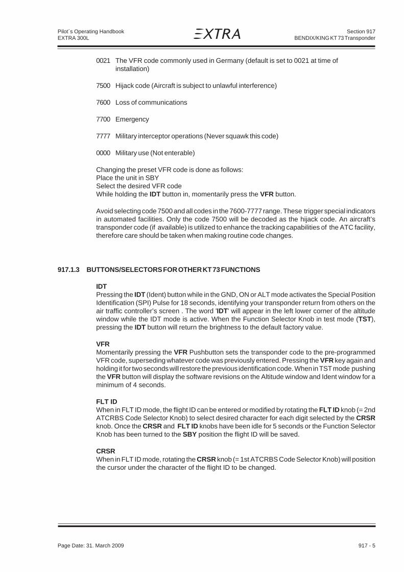
Section 917BENDIX/KING KT 73 Transponder
Page Date: 31. March 2009 917 - 5
Pilot´s Operating HandbookEXTRA 300L
0021 The VFR code commonly used in Germany (default is set to 0021 at time ofinstallation)
7500 Hijack code (Aircraft is subject to unlawful interference)
7600 Loss of communications
7700 Emergency
7777 Military interceptor operations (Never squawk this code)
0000 Military use (Not enterable)
Changing the preset VFR code is done as follows:Place the unit in SBYSelect the desired VFR codeWhile holding the IDT button in, momentarily press the VFR button.
Avoid selecting code 7500 and all codes in the 7600-7777 range. These trigger special indicatorsin automated facilities. Only the code 7500 will be decoded as the hijack code. An aircraft’stransponder code (if available) is utilized to enhance the tracking capabilities of the ATC facility,therefore care should be taken when making routine code changes.
917.1.3 BUTTONS/SELECTORS FOR OTHER KT 73 FUNCTIONS
IDTPressing the IDT (Ident) button while in the GND, ON or ALT mode activates the Special PositionIdentification (SPI) Pulse for 18 seconds, identifying your transponder return from others on theair traffic controller’s screen . The word 'IDT' will appear in the left lower corner of the altitudewindow while the IDT mode is active. When the Function Selector Knob in test mode (TST),pressing the IDT button will return the brightness to the default factory value.
VFRMomentarily pressing the VFR Pushbutton sets the transponder code to the pre-programmedVFR code, superseding whatever code was previously entered. Pressing the VFR key again andholding it for two seconds will restore the previous identification code. When in TST mode pushingthe VFR button will display the software revisions on the Altitude window and Ident window for aminimum of 4 seconds.
FLT IDWhen in FLT ID mode, the flight ID can be entered or modified by rotating the FLT ID knob (= 2ndATCRBS Code Selector Knob) to select desired character for each digit selected by the CRSRknob. Once the CRSR and FLT ID knobs have been idle for 5 seconds or the Function SelectorKnob has been turned to the SBY position the flight ID will be saved.
CRSRWhen in FLT ID mode, rotating the CRSR knob (= 1st ATCRBS Code Selector Knob) will positionthe cursor under the character of the flight ID to be changed.
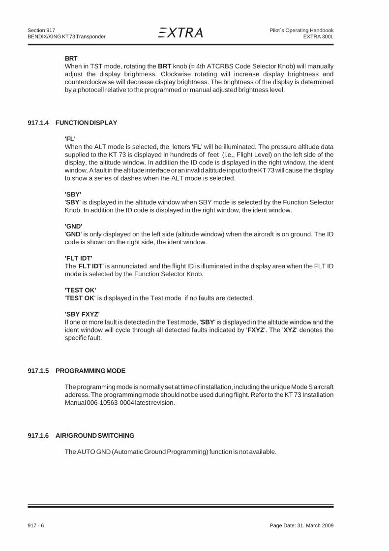
Section 917BENDIX/KING KT 73 Transponder
917 - 6 Page Date: 31. March 2009
Pilot´s Operating HandbookEXTRA 300L
BRTWhen in TST mode, rotating the BRT knob (= 4th ATCRBS Code Selector Knob) will manuallyadjust the display brightness. Clockwise rotating will increase display brightness andcounterclockwise will decrease display brightness. The brightness of the display is determinedby a photocell relative to the programmed or manual adjusted brightness level.
917.1.4 FUNCTION DISPLAY
'FL'When the ALT mode is selected, the letters 'FL' will be illuminated. The pressure altitude datasupplied to the KT 73 is displayed in hundreds of feet (i.e., Flight Level) on the left side of thedisplay, the altitude window. In addition the ID code is displayed in the right window, the identwindow. A fault in the altitude interface or an invalid altitude input to the KT 73 will cause the displayto show a series of dashes when the ALT mode is selected.
'SBY''SBY' is displayed in the altitude window when SBY mode is selected by the Function SelectorKnob. In addition the ID code is displayed in the right window, the ident window.
'GND''GND' is only displayed on the left side (altitude window) when the aircraft is on ground. The IDcode is shown on the right side, the ident window.
'FLT IDT'The 'FLT IDT' is annunciated and the flight ID is illuminated in the display area when the FLT IDmode is selected by the Function Selector Knob.
'TEST OK''TEST OK' is displayed in the Test mode if no faults are detected.
'SBY FXYZ'If one or more fault is detected in the Test mode, 'SBY' is displayed in the altitude window and theident window will cycle through all detected faults indicated by 'FXYZ'. The 'XYZ' denotes thespecific fault.
917.1.5 PROGRAMMING MODE
The programming mode is normally set at time of installation, including the unique Mode S aircraftaddress. The programming mode should not be used during flight. Refer to the KT 73 InstallationManual 006-10563-0004 latest revision.
917.1.6 AIR/GROUND SWITCHING
The AUTO GND (Automatic Ground Programming) function is not available.

Section 917BENDIX/KING KT 73 Transponder
Page Date: 31. March 2009 917 - 7
Pilot´s Operating HandbookEXTRA 300L
917.1.7 FAILURE ANNUNCIATION
If the unit detects an internal failure, FAIL annunciation light on the left side of the displays willilluminate.
917.2 LIMITATIONS
Not applicable.
917.3 EMERGENCY PROCEDURES
IMPORTANT CODES
7600 Loss of communications.
7500 Hijacking.
7700 Emergency (All secondary surveillance radar sites are ready to receive this code at alltimes).
See the Airman’s Information Manual (AIM) for a detailed explanation of identification codes.
917.4 NORMAL PROCEDURES
Not applicable.
917.5 PERFORMANCE
Not applicable.

Section 917BENDIX/KING KT 73 Transponder
917 - 8 Page Date: 31. March 2009
Pilot´s Operating HandbookEXTRA 300L
Left blank intentionally

Section 918BECKER ATC 2000 Transponder
Page Date: 15. December 2005 918 - 1
Pilot´s Operating HandbookEXTRA 300L
SECTION 918
BECKER ATC 2000 TRANSPONDER
Table of Contents
Paragraph PageSECTION 918 BECKER ATC 2000 TRANSPONDER
918.1 GENERAL ....................................................................................................................... 918-3918.1.1 Built-in Test ...................................................................................................................... 918-4918.1.2 Squawk selection ............................................................................................................ 918-4918.1.3 Mode A Operation ............................................................................................................ 918-5918.1.4 Mode A and C Operation ................................................................................................. 918-5
918.2 LIMITATIONS .................................................................................................................. 918-5
918.3 EMERGENCY PROCEDURES ....................................................................................... 918-5918.3.1 Important Codes .............................................................................................................. 918-5
918.4 NORMAL PROCEDURES............................................................................................... 918-6
918.5 PERFORMANCE ............................................................................................................ 918-6

Section 918BECKER ATC 2000 Transponder
918 - 2 Page Date: 15. December 2005
Pilot´s Operating HandbookEXTRA 300L
Left blank intentionally

Section 918BECKER ATC 2000 Transponder
Page Date: 15. December 2005 918 - 3
Pilot´s Operating HandbookEXTRA 300L
918.1 GENERAL
The Becker panel mounted ATC 2000 Transponder is a radio transmitter and receiver that fulfillsthe role of the airborne beacon equipment according to the requirements of the Air Traffic RadarBeacon System (ATCRBS). Its functionality includes replying to ATCRBS Mode A and Mode Cinterrogations.
It operates on radar frequencies, receiving ground radar interrogations at 1030 MHz andtransmitting a coded response of pulses to ground-based radar on a frequency of 1090 MHz. TheATC 2000 is equipped with IDENT capability that activates the Special Position Identification (SPI)pulse.
slortnoC noitpircseD noitcnuF
TSET/TLA/NO/YBS/FFOhctiwsedom
hctiwsyratornoitisoP-ruoFnoitisopyekenodna
ffodehctiwssirednopsnarTFFO)gnithgillenapfonoitpecxehtiw(
pu-mrawebutrettimsnarTYBS
AedomotsdnopserrednopsnarTNOedoctesehthtiwnoitagorretni
dnaAedomotsdnopserrednopsnarTTLAnoitagorretniCedom
,noitalumisnoitagorretniybtsetni-tliuBTSETputhgiltsumpmalYLPER
nottubTNEDI nottubhsuP rednopsnartehtnottubTNEDIehtgnisserPeslupIPSnastimsnart
pmalYLPER remmidhtiw,egnaro,pmaL tesytisnetni;sdnopserrednopsnartfipusthgiLremmidlacinahcemafosnaemyb
sehctiwsgnidoc4 thgiehtiwsehctiwsyratoRsnoitisop
gnittimrep7777ot0000morfedocehtgnitteSsnoitanibmoctigidtnereffid6904
tuodaeredoC tigidhcae,tuodaerlatigiD7ot0morf
7777ot0000morfgnidocfonoitacidnI

Section 918BECKER ATC 2000 Transponder
918 - 4 Page Date: 15. December 2005
Pilot´s Operating HandbookEXTRA 300L
N O T E
The ATC 2000 owner accepts all responsibility for obtaining the proper license beforeusing the transponder.
N O T I C E
Damage possible due to current peaks.Do not switch on or off the transponder until the engine has been startet or stoppedrespectively.
918.1.1 BUILT-IN TEST
1 Position mode switch from OFF to SBY. Operate the transponder approx. 60s in theSBY position since transmitting tube must warm up and stabilize prior to operation. It is,however, possible to skip the SBY position without danger for the transmitter tube,since the latter is safeguarded by cavity protection circuit which also requires approx.60s to warm up.
2 Turn mode switch as far as it will go to TEST (key position) in which the transpondersimulates interrogation, prompting a reply. The reply indication is given by the replylamp illuminating.
918.1.2 SQUAWK SELECTION
Squawk selection is done with the four rotating knobs to provide 4096 identification codes.Important Codes:
1200 The VFR code for any altitude in the US (Refer to ICAO standards elsewhere)
7000 The VFR code commonly used in Europe (Refer to ICAO standards)
0021 The VFR code commonly used in Germany (default is set to 0021 at time ofinstallation)
7500 Hijack code (Aircraft is subject to unlawful interference)
7600 Loss of communications
7700 Emergency
7777 Military interceptor operations (Never squawk this code)
0000 Military use (Not enterable)
Avoid selecting code 7500 and all codes in the 7600-7777 range. These trigger special indicatorsin automated facilities. Only the code 7500 will be decoded as the hijack code. An aircraft’stransponder code (if available) is utilized to enhance the tracking capabilities of the ATC facility,therefore care should be taken when making routine code changes.
Page Date: 20. January 2016

Section 918BECKER ATC 2000 Transponder
Page Date: 15. December 2005 918 - 5
Pilot´s Operating HandbookEXTRA 300L
918.1.3 MODE A OPERATION
1 Activate the transponder on ATC request only. To enshure instant readiness, positionthe mode switch to SBY (standby) during the flight.
2 Set the code requested by ATC using the four coding switches. Set two-digit codenumbers in the first two windows of the readout.
N O T E
Only operate the coding switches in the SBY (standby) mode.
3 Switch the mode switch ON on ATC request, the transponder then responding to modeA interrogation with dialed code, as indicated by the REPLY lamp coming on.
4 Only press the IDENT button briefly when requested by ATC, causing a specialidentification pulse (SPI pulse) being transmitted, permitting instant identification of theaircraft on the ATC radar system.
918.1.4 MODE A AND C OPERATION
1 Postion mode switch to ALT on ATC request only. The transponder then responds withdialed code, causing REPLY lamp to light up and additionally transmits the height ofthe aircraft to ATC.
2 Press the IDENT button briefly when requested by ATC, causing a special identificationpulse (SPI pulse) being transmitted, permitting instant identification of the aircraft onthe ATC radar system.
918.2 LIMITATIONS
Not applicable.
918.3 EMERGENCY PROCEDURES
918.3.1 IMPORTANT CODES
7600 Loss of communications.
7500 Hijacking.
7700 Emergency (All secondary surveillance radar sites are ready to receive this code at alltimes).
See the Airman’s Information Manual (AIM) for a detailed explanation of identification codes.
Page Date: 20. January 2016

Section 918BECKER ATC 2000 Transponder
918 - 6 Page Date: 15. December 2005
Pilot´s Operating HandbookEXTRA 300L
918.4 NORMAL PROCEDURES
Not applicable
918.5 PERFORMANCE
Not applicable

Page Date: 15. December 2005 919 - 1
Pilot´s Operating HandbookEXTRA 300L
Section 919BECKER ATC 4401 Transponder
SECTION 919
BECKER ATC 4401 TRANSPONDER
Table of Contents
Paragraph PageSECTION 919 BECKER ATC 4401 TRANSPONDER
919.1 GENERAL ....................................................................................................................... 919-3919.1.1 Controls and indicators .................................................................................................... 919-4919.1.2 Switching on the unit (pre-flight check) ............................................................................ 919-4919.1.3 Squawk selection ............................................................................................................ 919-5919.1.4 Flight operation in Mode A (transponder reply code only) ................................................ 919-7919.1.5 Flight operation in Mode A+C (reply code and altitude code) ........................................... 919-7919.1.6 Squawk Ident .................................................................................................................. 919-7919.1.7 Test ................................................................................................................................. 919-7919.1.8 Configuration Mode ......................................................................................................... 919-8
919.2 LIMITATIONS .................................................................................................................. 919-8
919.3 EMERGENCY PROCEDURES ....................................................................................... 919-8919.3.1 Important Codes .............................................................................................................. 919-8
919.4 NORMAL PROCEDURES............................................................................................... 919-8
919.5 PERFORMANCE ............................................................................................................ 919-8

919 - 2 Page Date: 15. December 2005
Pilot´s Operating HandbookEXTRA 300L
Section 919BECKER ATC 4401 Transponder
Left blank intentionally

Page Date: 15. December 2005 919 - 3
Pilot´s Operating HandbookEXTRA 300L
Section 919BECKER ATC 4401 Transponder
919.1 GENERAL
The Becker panel mounted ATC 4401 Transponder is a radio transmitter and receiver that fulfillsthe role of the airborne beacon equipment according to the requirements of the Air Traffic RadarBeacon System (ATCRBS). Its functionality includes replying to ATCRBS Mode A and Mode Cinterrogations.
It operates on radar frequencies, receiving ground radar interrogations at 1030 MHz andtransmitting a coded response of pulses to ground-based radar on a frequency of 1090 MHz. TheATC 4401 is equipped with IDENT capability that activates the Special Position Identification (SPI)pulse.
N O T E
The ATC 4401 owner accepts all responsibility for obtaining the proper license beforeusing the transponder. Refer to Becker Pilot's Guide.
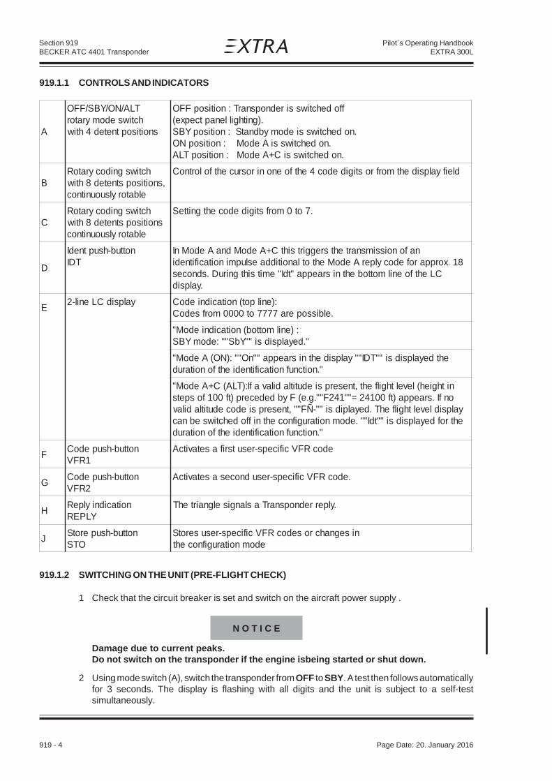
919 - 4 Page Date: 15. December 2005
Pilot´s Operating HandbookEXTRA 300L
Section 919BECKER ATC 4401 Transponder
919.1.1 CONTROLS AND INDICATORS
919.1.2 SWITCHING ON THE UNIT (PRE-FLIGHT CHECK)
1 Check that the circuit breaker is set and switch on the aircraft power supply .
N O T I C E
Damage due to current peaks.Do not switch on the transponder if the engine isbeing started or shut down.
2 Using mode switch (A), switch the transponder from OFF to SBY. A test then follows automaticallyfor 3 seconds. The display is flashing with all digits and the unit is subject to a self-testsimultaneously.
A
TLA/NO/YBS/FFOhctiwsedomyrator
snoitisoptneted4htiw
ffodehctiwssirednopsnarT:noitisopFFO.)gnithgillenaptcepxe(
.nodehctiwssiedomybdnatS:noitisopYBS.nodehctiwssiAedoM:noitisopNO
.nodehctiwssiC+AedoM:noitisopTLA
BhctiwsgnidocyratoR
,snoitisopstneted8htiwelbatorylsuounitnoc
dleifyalpsidehtmorfrostigidedoc4ehtfoenonirosrucehtfolortnoC
ChctiwsgnidocyratoR
snoitisopstneted8htiwelbatorylsuounitnoc
.7ot0morfstigidedocehtgnitteS
D
nottub-hsuptnedITDI
nafonoissimsnartehtsreggirtsihtC+AedoMdnaAedoMnI81.xorpparofedocylperAedoMehtotlanoitiddaeslupminoitacifitnedi
CLehtfoenilmottobehtnisraeppa"tdI"emitsihtgniruD.sdnoces.yalpsid
EyalpsidCLenil-2 :)enilpot(noitacidniedoC
.elbissopera7777ot0000morfsedoC
:)enilmottob(noitacidniedoM"".deyalpsidsi""YbS"":edomYBS
ehtdeyalpsidsi""TDI""yalpsidehtnisraeppa""nO"":)NO(AedoM"".noitcnufnoitacifitnediehtfonoitarud
nithgieh(levelthgilfeht,tneserpsiedutitladilavafI:)TLA(C+AedoM"onfI.sraeppa)tf00142=""142F"".g.e(Fybdedecerp)tf001fospets
yalpsidlevelthgilfehT.deyalpidsi""-ÑF"",tneserpsiedocedutitladilavehtrofdeyalpsidsi""tdI"".edomnoitarugifnocehtniffodehctiwsebnac
".noitcnufnoitacifitnediehtfonoitarud
Fnottub-hsupedoC
1RFVedocRFVcificeps-resutsrifasetavitcA
Gnottub-hsupedoC
2RFV.edocRFVcificeps-resudnocesasetavitcA
HnoitacidniylpeR
YLPER.ylperrednopsnarTaslangiselgnairtehT
Jnottub-hsuperotS
OTSnisegnahcrosedocRFVcificeps-resuserotS
edomnoitarugifnoceht
Page Date: 20. January 2016

Page Date: 15. December 2005 919 - 5
Pilot´s Operating HandbookEXTRA 300L
Section 919BECKER ATC 4401 Transponder
3 After the switch-on test has elapsed and no error-message is written in the display, the transponderswitches to the mode set on the mode switch (A).
N O T E
The blind encoder is only powered if the transponder is not switched OFF (at least SBY).A blind encoder needs a warm-up time (sometimes a several minutes). Thereforealthough the solid state transponder needs no warm-up time, turn the transponder to SBYimmediately after starting the engine.
919.1.3 SQUAWK SELECTION
1 The transponder remains switched in the standby mode until requested by the ground station (ATC)to transmit a code, e.g. „squawk alpha 6426“.
2 Using the double rotary switch (B,C) set the 4-digit code requested by ATC as follows :
a Using switch (B) move the cursor to the particular digit. Digits 0 to 7 can then be set using switch(C).
N O T E S
If switch (B) is turned clockwise or counter-clockwise, the cursor is moved one position tothe right or the left. The cursor appears only in the code display and is indicated by theflashing digit. If no cursor is visible, the first digit flashes after a clockwise rotation and thelast digit after a counter-clockwise rotation. When the code is being changed in the ONor ALT position, the transponder temporarily switches to the standby mode.
The active time of the cursor and the rate of flashing can be changed in the configurationmode.
b If the cursor is not moved again within of 3 seconds (can be changed in configuration mode) or ifthe cursor is moved so far that it can no longer be seen in the display field or the identification switchis pressed (in the ON or ALT mode), the code currently set is switched active.
N O T E S
Whilst settings are taking place, the transmission branch of the transponder is inhibitedto prevent unintentional transmission.
If only two digits were named by ATC, e.g. „Squawk alpha 64“, then a zero is to be usedfor positions three and four, i.e. „6400“.
c The last used code is stored in each case and is also activated when the transponder is switchedon.
SPECIAL VFR CODINGS
Two user-specific VFR codes can be stored and activated on the transponder.
1 Storing a new VFR code:
a Set the code to be stored in accordance with section B.

919 - 6 Page Date: 15. December 2005
Pilot´s Operating HandbookEXTRA 300L
Section 919BECKER ATC 4401 Transponder
b Press store push-button STO (J), the set code then flashes.
c Press the VFR1 push-button (F) or the VFR2 push-button (G) wit-hin 3 seconds to store the codeunder the corresponding button.
d If neither button (F) or (G) is pressed within 3 seconds, the flashing stops and the storage operationis aborted.
N O T E
If one of the two buttons (F) or (G) is pressed without the STO button having been pressedbeforehand, then the stored code allocated this button appears in the code display and isswitched to active after 3 seconds (can be changed in the configuration mode). If the samebutton is again pressed within 3 seconds, the previous code appears.
2 Activation of the VFR codes:
a Press the VFR push-button 1 or 2 (F, G). The selected code is then displayed. After 3 seconds,the displayed code becomes activate and overwrites the previously-set reply code.
b Pressing button (F) or (G) again within 3 seconds reactivates the previously-set reply code.
N O T E
When the unit is delivered, the store buttons are not assigned a code. This means that ifthese buttons are pressed for 0.5 seconds, „——“ is shown in the code display and thetransponder then switches back to the previously-active code.
IMPORTANT CODES:
1200 The VFR code for any altitude in the US (Refer to ICAO standards elsewhere)
7000 The VFR code commonly used in Europe (Refer to ICAO standards)
0021 The VFR code commonly used in Germany (default is set to 0021 at time ofinstallation)
7500 Hijack code (Aircraft is subject to unlawful interference)
7600 Loss of communications
7700 Emergency
7777 Military interceptor operations (Never squawk this code)
0000 Military use (Not enterable)
Avoid selecting code 7500 and all codes in the 7600-7777 range. These trigger special indicatorsin automated facilities. Only the code 7500 will be decoded as the hijack code. An aircraft’stransponder code (if available) is utilized to enhance the tracking capabilities of the ATC facility,therefore care should be taken when making routine code changes.
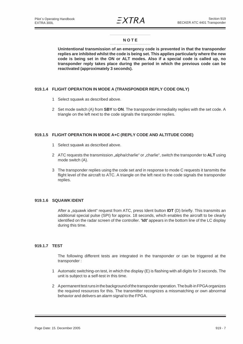
Page Date: 15. December 2005 919 - 7
Pilot´s Operating HandbookEXTRA 300L
Section 919BECKER ATC 4401 Transponder
N O T E
Unintentional transmission of an emergency code is prevented in that the transponderreplies are inhibited whilst the code is being set. This applies particularly where the newcode is being set in the ON or ALT modes. Also if a special code is called up, notransponder reply takes place during the period in which the previous code can bereactivated (approximately 3 seconds).
919.1.4 FLIGHT OPERATION IN MODE A (TRANSPONDER REPLY CODE ONLY)
1 Select squawk as described above.
2 Set mode switch (A) from SBY to ON. The transponder immediality replies with the set code. Atriangle on the left next to the code signals the tranponder replies.
919.1.5 FLIGHT OPERATION IN MODE A+C (REPLY CODE AND ALTITUDE CODE)
1 Select squawk as described above.
2 ATC requests the transmission „alpha/charlie“ or „charlie“, switch the transponder to ALT usingmode switch (A).
3 The transponder replies using the code set and in response to mode C requests it tansmits theflight level of the aircraft to ATC. A triangle on the left next to the code signals the transponderreplies.
919.1.6 SQUAWK IDENT
After a „squawk ident“ request from ATC, press Ident button IDT (D) briefly. This transmits anadditional special pulse (SPI) for approx. 18 seconds, which enables the aircraft to be clearlyidentified on the radar screen of the controller. 'Idt' appears in the bottom line of the LC displayduring this time.
919.1.7 TEST
The following different tests are integrated in the transponder or can be triggered at thetransponder :
1 Automatic switching-on test, in which the display (E) is flashing with all digits for 3 seconds. Theunit is subject to a self-test in this time.
2 A permanent test runs in the background of the transponder operation. The built-in FPGA organizesthe required resources for this. The transmitter recognizes a missmatching or own abnormalbehavior and delivers an alarm signal to the FPGA.

919 - 8 Page Date: 15. December 2005
Pilot´s Operating HandbookEXTRA 300L
Section 919BECKER ATC 4401 Transponder
3 A further test of the unit is triggered, if the VFR1 button (F) and VFR2 button (G) are pressedsimultaneously. At this test all segments must flash into display (E) as long as the buttons arepushed. Additional the transmitter and evaluation are tested on correct function in the SBY, ONand ALT modes.
4 In case of a failure appears the report e.g. 'E10' in the top line of the display. Switch OFF thetransponder at such 'E' fault indications.
919.1.8 CONFIGURATION MODE
The configuration Mode is used to set the unit on the ground and must not be called up in flight.Refer to BECKER's Pilot's Guide for further information.
919.2 LIMITATIONS
Not applicable.
919.3 EMERGENCY PROCEDURES
919.3.1 IMPORTANT CODES
7600 Loss of communications.
7500 Hijacking.
7700 Emergency (All secondary surveillance radar sites are ready to receive this code at alltimes).
See the Airman’s Information Manual (AIM) for a detailed explanation of identification codes.
919.4 NORMAL PROCEDURES
Not applicable
919.5 PERFORMANCE
Not applicable

Page Date: 31. March 2009 920 - 1
Pilot´s Operating HandbookEXTRA 300L
Section 920BECKER BXP 6401 Transponder
SECTION 920
BECKER BXP 6401 TRANSPONDER
Table of Contents
Paragraph PageSECTION 920 BECKER ATC 6401 TRANSPONDER
920.1 GENERAL ....................................................................................................................... 920-3920.1.1 Controls and Indicators ................................................................................................... 920-4920.1.2 Switching on the Unit (pre-flight check) ........................................................................... 920-4920.1.3 Display ............................................................................................................................ 920-5920.1.4 Squawk Selection ............................................................................................................ 920-5920.1.5 Squawk Ident .................................................................................................................. 920-6920.1.6 Selftests of the Unit (BITs) ............................................................................................... 920-6920.1.7 Selection Mode................................................................................................................ 920-7920.1.8 Flight Operation in Mode A/C/S (reply code and altitude code) ........................................ 920-9920.1.9 VFR Code Activation ..................................................................................................... 920-10920.1.10 Configuration Mode ....................................................................................................... 920-10
920.2 LIMITATIONS ................................................................................................................ 920-10
920.3 EMERGENCY PROCEDURES ..................................................................................... 920-10920.3.1 Important Codes ............................................................................................................ 920-10
920.4 NORMAL PROCEDURES............................................................................................. 920-10
920.5 PERFORMANCE .......................................................................................................... 920-10

920 - 2 Page Date: 31. March 2009
Pilot´s Operating HandbookEXTRA 300L
Section 920BECKER BXP 6401 Transponder
Left blank intentionally

Page Date: 31. March 2009 920 - 3
Pilot´s Operating HandbookEXTRA 300L
Section 920BECKER BXP 6401 Transponder
920.1 GENERAL
The Becker panel mounted BXP 6401 Transponder is a radio transmitter and receiver that fulfillsthe role of the airborne beacon equipment according to the requirements of the Air Traffic RadarBeacon System (ATCRBS). Its functionality includes replying to ATCRBS Mode A, C and Mode Sinterrogations.
It operates on radar frequencies, receiving ground radar interrogations at 1030 MHz andtransmitting a coded response of pulses to ground-based radar on a frequency of 1090 MHz. TheBXP 6401 is equipped with IDENT capability that activates the Special Position Identification (SPI)pulse.
N O T E
The BXP 6401 owner accepts all responsibility for obtaining the proper license beforeusing the transponder. Refer to Becker Pilot's Guide.

920 - 4 Page Date: 31. March 2009
Pilot´s Operating HandbookEXTRA 300L
Section 920BECKER BXP 6401 Transponder
920.1.1 CONTROLS AND INDICATORS
920.1.2 SWITCHING ON THE UNIT (PRE-FLIGHT CHECK)
1 Check that the circuit breaker is set and switch on the aircraft power supply .
N O T I C E
Damage possible due to current peaks.Do not switch on the transponder if the engine is being started or shut down.
2 Using mode selector (A), switch the transponder from OFF to SBY. A test then followsautomatically for 1 seconds. The display shows 'WAIT' and the unit is subject to a self-testsimultaneously.
3 After the switch-on test has elapsed and no error-message is written in the display, thetransponder switches to the mode set on the mode selector (A).
A rotceleSedoM 4htiwhctiwsyratoRsnoitisop
ffodehctiwssirednopsnarT:noitisopFFOnodehctiwssiedomybdnatS:noitisopYBS
noissimsnarT.nodehctiwssiS/AedoM:noitisopNOdesserppussinoitamrofniedutitlafo
ehtdnanodehctiwssiS/C/AedoM:noitisopTLA.dettimsnartsinoitamrofniedutitla
B hctiwsyratoR redocnelacitpoyratoR)Cfoedomyrator(
sgnittesegnahcothctiwsyratoR)nrutrepspets61(
C nottuB nottub-hsuP)Bfoedom(
morfrosgnittesroftigidottigidmorfpmujothsuP;txenehtotunemeno
yekretnenasadesuyllareneg
D TDI nottub-hsuP otnoitid-dani)IPS(reifitnedIlaicepSehtsetavitcAsihtgnirud;sdnoces81.xorpparofedocylpereht
yalpsidCLehtnisraeppa"DI"emit
E 1trap,yalpsiD yalpsidDCLenil-2 :snoitamrofnigniwollofehtsyalpsiDworpotehtninoitacidniedoc-
wormottobehtnilevelthgilf-wormottobehtnisnoitamrofnisuoirav-
)H.feRees(edistfelehtnosrotacidnilanoitidda-
F OTS nottub-hsuP sgnittesehtotseulavdetcelesehtserotS
G LES nottub-hsuP unemehtstcelesdnasnepO
H 2trap,yalpsiD srotacidniDCL rofDI,ylperrofR(,srotacidnilanoitiddasyalpsiDNORDPXrofNOroedomTLARDPXrofTLA,tnedI
)levelthgilfrofLF,edom
J RFV nottub-hsuP yalpsidehtfoworreppuehtniedocRFVsetavitcA
Page Date: 20. January 2016

Page Date: 31. March 2009 920 - 5
Pilot´s Operating HandbookEXTRA 300L
Section 920BECKER BXP 6401 Transponder
N O T E
The blind encoder is only powered if the transponder is not switched OFF (at least SBY).A blind encoder needs a warm-up time (sometimes a several minutes). Therefore althoughthe solid state transponder needs no warm-up time, turn the transponder to SBYimmediately after starting the engine.
920.1.3 DISPLAY
Transponder’s code is displayed in the top line using high readability font, at all times in modesSBY, ON, ALT. Depending on the configuration settings, the Aircraft Identification (AI) or FlightNumber (FN) is displayed in the bottom line. Flight level is displayed in ALT mode in the bottomline of the display (altitude= FL x 100 in ft).
920.1.4 SQUAWK SELECTION
1 The transponder remains switched in the standby mode until requested by the ground station(ATC) to transmit a code, e.g. „squawk alpha 6426“.
2 Using the rotary switch (B) and the button (C) set the 4-digit code requested by ATC as follows:
a Using switch (C) move the cursor to the particular digit. Digits 0 to 7 can then be set using the rotaryswitch (B).
N O T E S
Whilst settings are taking place, the transmission branch of the transponder is inhibitedto prevent unintentional transmission.
If only two digits were named by ATC, e.g. „Squawk alpha 64“, then a zero is to be usedfor positions three and four, i.e. „6400“.
b The last used code is stored in each case and is also activated when the transponder is switchedon.
IMPORTANT CODES:
1200 The VFR code for any altitude in the US (Refer to ICAO standards elsewhere)
7000 The VFR code commonly used in Europe (Refer to ICAO standards)
0021 The VFR code commonly used in Germany (default is set to 0021 at time ofinstallation)
7500 Hijack code (Aircraft is subject to unlawful interference)
7600 Loss of communications
7700 Emergency

920 - 6 Page Date: 31. March 2009
Pilot´s Operating HandbookEXTRA 300L
Section 920BECKER BXP 6401 Transponder
7777 Military interceptor operations (Never squawk this code)
0000 Military use (Not enterable)
Avoid selecting code 7500 and all codes in the 7600-7777 range. These trigger special indicatorsin automated facilities. Only the code 7500 will be decoded as the hijack code. An aircraft’stransponder code (if available) is utilized to enhance the tracking capabilities of the ATC facility,therefore care should be taken when making routine code changes.
N O T E
Unintentional transmission of an emergency code is prevented in that the transponderreplies are inhibited whilst the code is being set. This applies particularly where the newcode is being set in the ON or ALT modes. Also if a special code is called up, notransponder reply takes place during the period in which the previous code can bereactivated (approximately 3 seconds).
920.1.5 SQUAWK IDENT
After a „squawk ident“ request from ATC, press Ident button IDT (D) briefly. This transmits anadditional special pulse (SPI) for approx. 18 seconds, which enables the aircraft to be clearlyidentified on the radar screen of the controller. 'Idt' appears in the bottom line of the LC display duringthis time.
920.1.6 SELFTESTS OF THE UNIT (BITS)
The following different tests are integrated in the transponder or can be triggered at the transponder:
1 The IBIT (Initiated Built-in Test) can be activated in any mode (excluding the configuration mode)with the push of (F) and (G) at the same time. The action starts with the leading edge of the secondpushed button. The IBIT works as follows in all modes:
The test starts with all available test routines including the transmitter test routine. During the test,'IBIT' is indicated on the display.The test takes not longer than 1 second. If the IBIT wassuccessful, the XPDR switches immediately into the normal operating mode. During the IBIT anyaction from other switches is not recognized.
Negative results of the IBIT are indicated on the display with 'FAILURE'. The transponder maybe not switched into ON or ALT mode if any failure was found.
2 The CBIT (Continuous Built-in Test) works as follows:
The continuous BIT acts as a kind of watchdog during operation. Negative results of the CBIT areindicated on the display with 'FAILURE'. In this case the transponder may be not switched intoON or ALT mode (display indication of operating mode set to 'SBY') if any failure was found.
3 The PBIT (Power-on Built-in Test) works as follows:
The XPDR has a power-on BIT after switching on. During the PBIT any action from other switchesare not accepted.

Page Date: 31. March 2009 920 - 7
Pilot´s Operating HandbookEXTRA 300L
Section 920BECKER BXP 6401 Transponder
During the PBIT the XPDR is in the SBY mode but this is not indicated on the display. The operatingmode indication on the display starts immediately after finalisation of the PBIT.
Negative results are indicated on the display with 'FAILURE'. The transpondermay be notswitched into ON or ALT mode if any failure was found.
The PBIT takes not longer than 1 second. If the test was successful, the XPDR switchesimmediately into the normal operating mode.
920.1.7 SELECTION MODE
Press SEL button (G) and rotate encoder (B) for selection. In selection mode additional informationis displayed in the bottom line of the display. Some of the data are editable, some are read only:
AIRCRAFT IDENTIFICATION (AI OR FN)
With flight plan:The definition out of the flight plan: e.g. Flight Number or Company Call Sign
Without flight plan (VFR):Tail Number (Call Sign)
The indication of 'AI' in the bottom line of the display is in mode SBY and ON only if selected inconfiguration menu. The Aircraft Identifier (fixed) is available in any mode after pressing SEL button(G) and turning the rotary encoder (B). The default value for AI is the Tail Number of the aircraft andis stored in the Address Module.
If a flight plan exists, it has to be checked, which AI has to be used. If a Flight Number is assignedit has to be entered. If a Company Call Sign is mentioned, this has to be entered. To enter it seebelow. It will be stored in the EEPROM of the control head. In this case the indication on the displaychanges to 'FN' (Flight Number). If the Call Sign (Tail Number) is mentioned, no change, as it isthe default setting from the Address Module.
RFV gnitteserpedoc6904 elbatide
IAreifitnedItfarcriA
)rebmuNliaT(ybdecalperebna(eludomsserddamorfylnodaer;dexif
.deyalpsidsi"---------",derotssiIAdilavonfI.)NF
NFrorebmuNthgilF
ngiSllaCynapmoC;elbatide
"FEDIA"gnitcelesyb)dexif(IAybdecalperebnac
AAsserddAtfarcriA
)OACItib-42(eludomsserddamorfylnodaer;dexif
)tfarcriahcaerofrebmuneuqinu(
AM deepsriAmumixaM eludomsserddamorfylnodaer;dexif
TA epyTtfarcriA eludomsserddamorfylnodaer;dexif
GFC noitarugifnoC ylnoedomYBSnielbaliava
SNI putesnoitallatsnI drowssapybdetcetorp;ylnoedomYBSnielbaliava

920 - 8 Page Date: 31. March 2009
Pilot´s Operating HandbookEXTRA 300L
Section 920BECKER BXP 6401 Transponder
SETTING THE FLIGHT NUMBER:
1 Press SEL button (G) to enter the select mode.
2 Rotate (B) until 'AI' is displayed.
3 Push (C) to switch to 'FN'. The cursor is set on the first character.
4 Rotate (B) to change this character.
5 Push (C) to set the cursor to the next character.
6 Repeat steps 4 and 5 until the flight number is entered.
7 If the flight number consists of less than 7 characters, put a space at the end to fill the remainingcharacters with spaces.
8 Store the changes with STO button (F). For leaving the setting procedure without storing, pushthe SEL button (G).
N O T E
Aircraft Identifier / Flight Number consists of max. 7 characters (on the left- hand sideoriented). No dashes or spaces shall be included. If the FN con- sists of less than 7characters, the remaining characters on the right side shall be filled with spaces.
SWITCHING BACK TO DEFAULT AI:
1 Press SEL button (G) to enter the select mode.
2 Rotate (B) to the indication 'FN=XXXXXXXX'.
3 First push on (C) indicates'FN=AI DEF' (inverted).
4 Can be set to 'AI=DEF' with STO button (F).
CHANGING THE FLIGHT NUMBER:
1 Press SEL button (G).
2 Rotate (B) until 'FN' is displayed.
3 Push (C) twice to enter the FN editing mode.
4 Change the FN as described above.

Page Date: 31. March 2009 920 - 9
Pilot´s Operating HandbookEXTRA 300L
Section 920BECKER BXP 6401 Transponder
VFR CODE PRESETTING
Press the SEL button (G) to get into configuration mode (selection is indicated in the left bottomcorner of the display under the operating mode indication).
1 Rotate (B) to the indication 'VFR=XXXX'.
2 First push to button (C) now left digit of the code is inverted.
3 Now the digit can be changed with (B).
4 Second push to button (C) now next left digit of the code is inverted.
5 The next digit can be changed with (B)
6 and the same for next digits.
7 Fifth push to button (C) now again first digit is inverted.
8 Changes can be stored with STO button (F) at any time, inversion stops in this case.
9 A VFR code that was preset in this way can be activated as described in chapter VFR CodeActivation.
10 A timeout for inversion (10 sec) is introduced if no action happens. Nothing stored, as long as (F)is not pressed.
N O T E
It is possible to leave the setting procedure with SEL button (G) at any time and normalmode is available then. Indication SEL on the display changes back to mode indication.If STO button (F) was not used, no change has been stored.
920.1.8 FLIGHT OPERATION IN MODE A/C/S (REPLY CODE AND ALTITUDE CODE)
1 When ATC requests the transmission „squawk“, switch the transponder to ALT using mode switch(A).
N O T E
In exceptions the altitude has to be turned off, i.e. switch the transponder to ON usingmode switch (A).
2 The transponder replies using the selected Code and in response to mode C interrogation ittransmits the altitude of the aircraft to ATC. A 'R' on the left next to the Code on the display signalsthe transponder replies.
N O T E
Switch the transponder to Stand-by (SBY), if the Code has to be changed. Otherwise ifcould happen that a Code with a special meaning (see chapter K, e.g. highjack) will betransmitted and unwanted actions could take place.

920 - 10 Page Date: 31. March 2009
Pilot´s Operating HandbookEXTRA 300L
Section 920BECKER BXP 6401 Transponder
920.1.9 VFR CODE ACTIVATION
1 Press the VFR push-button (J). The preselected code is then displayed. After 3 seconds, thedisplayed code gets active and overwrites the previously-set reply code.
2 Pressing push-button (J) again within 3 seconds reactivates the previously-set reply code.
N O T E
When the unit is delivered, the VFR button is not assigned a code. This means that if thisbutton is pressed for 0.5 seconds, „——“ is shown in the code display and the transponderthen switches back to the previously-active code.
920.1.10 CONFIGURATION MODE
The configuration mode is available from SBY mode only. To get into configuration mode pressbutton SEL (G), turn rotary encoder (B) until 'CFG' appears in the bottom row of the display. Referto BECKER’s Pilot’s Guide for available options.
920.2 LIMITATIONS
Not applicable.
920.3 EMERGENCY PROCEDURES
920.3.1 IMPORTANT CODES
7600 Loss of communications.
7500 Hijacking.
7700 Emergency (All secondary surveillance radar sites are ready to receive this code at alltimes).
See the Airman’s Information Manual (AIM) for a detailed explanation of identification codes.
920.4 NORMAL PROCEDURES
Not applicable
920.5 PERFORMANCE
Not applicable

Page Date: 5. December 2008 921 - 1
Pilot´s Operating HandbookEXTRA 300L
Section 921Lycoming AEIO-580-B1A Engine
SECTION 921
LYCOMING AEIO-580-B1A ENGINE
Table of Contents
Paragraph PageSECTION 921
921.1 GENERAL.........................................................................................................................921-3
921.2 LIMITATIONS ...................................................................................................................921-3921.2.1 Engine Limitations ............................................................................................................ 921-3921.2.2 Weight Limits ................................................................................................................... 921-4921.2.3 Propeller Limitations ......................................................................................................... 921-4921.2.4 Operating Placards ...........................................................................................................921-4921.2.5 Instrument Markings ......................................................................................................... 921-5921.2.6 Maximum Operating Altitude .............................................................................................921-5
921.3 EMERGENCY PROCEDURES...........................................................................................921-5
921.4 NORMAL PROCEDURES .................................................................................................921-5921.4.1 Noise Level .......................................................................................................................921-5
921.5 PERFORMANCE ..............................................................................................................921-6921.5.1 Cruise Performance Chart Configuration 1 .........................................................................921-7921.5.2 Range Configuration 1 .......................................................................................................921-8921.5.3 Endurance Configuration 1 ................................................................................................921-9921.5.4 Cruise Performance Chart Configuration 2 ....................................................................... 921-10921.5.5 Range Configuration 2 ..................................................................................................... 921-11921.5.6 Endurance Configuration 2 .............................................................................................. 921-12
921.6 WEIGHT AND BALANCE ............................................................................................... 921-13
921.7 DESCRIPTION ............................................................................................................... 921-13
Page Date: 20. January 2016

921 - 2 Page Date: 5. December 2008
Pilot´s Operating HandbookEXTRA 300L
Section 921Lycoming AEIO-580-B1A Engine
Left blank intentionally

Page Date: 5. December 2008 921 - 3
Pilot´s Operating HandbookEXTRA 300L
Section 921Lycoming AEIO-580-B1A Engine
921.1 GENERAL
As an alternative to the Lycoming AEIO-540-L1B5 engine the EXTRA 300L can be equipped withan AEIO-580-B1A engine. It is a six-cylinder, horizontally opposed, aircooled, direct drive, fuelinjection engine with inverted oil system.
The EXTRA 300L with AEIO-580-B1A engine is available in one of the following fuel tankconfigurations ex factory, both combined with a wing tank of 120 L (31.7 US gal) capacity:Configuration 1: Acro and center tank with 51 L (13.4 US gal) total fuel capacity
(refer to section 1 thru 7 of this handbook)Configuration 2: Acro and center tank with 69 L (18.2 US gal) total fuel capacity
The AEIO-580-B1A engine can be operated with the following propellers:1) Type MTV-9-B-C/C 200-15 3-blade constant speed2) Type MTV-14-B-C/C 190-17 4 blade constant speed3) Type MTV-9-B-C/C 198-25 3-blade constant speed
921.2 LIMITATIONS
The following data deviate from the values given in Section 2 of this handbook:
921.2.1 Engine Limitations
a) Rotational Speed:Maximum Take-Off and Maximum Continuous: 2700 RPM*
N O T E *
Applicable RPM limitations approved for individual propeller types must be observed.Refer to Section 2.5 eligible for the MTV-9-B-C/C 200-15 & MTV-14-B-C/C 190-17 as wellas Section 921.2.3 eligible for the MTV-9-B-C/C 198-25 propeller.
b) Fuel (configuration 2)Total fuel capacity: 189 L (49.9 US gal)Usable fuel capacity in the system: 187 L (49.4 US gal).Acro & Center Tank capacity: 69 L (18.2 US gal)Usable fuel capacity for acrobatic: 67 L (17.7 US gal)
c) Fuel pressure (at inlet to fuel injector):Max: 448.2 kPa (65 psig)Min: 200.0 kPa (29 psig)Min Idle: 82.7 kPa (12 psig)
d) Cylinder head temperature:Max: 241 °C (465°F)
Page Date: 8. October 2009

921 - 4 Page Date: 5. December 2008
Pilot´s Operating HandbookEXTRA 300L
Section 921Lycoming AEIO-580-B1A Engine
921.2.2 Weight Limits
Max allowed empty weight:-Normal category configuration 1 742 kg (1636 lb) configuration 2 729 kg (1607 lb)-Acrobatic category single seat operation / ACRO I configuration 1 698 kg (1540 lb) configuration 2 686 kg (1512 lb) double seat operation / ACRO II 662 kg (1460 lb) double seat operation / ACRO III 742 kg (1636 lb)
921.2.3 Propeller Limitations
The MTV-9-B-C/C 198-25 propeller may be operated only with the AEIO-580-B1A engine.
With respect to the noise level (refer to paragraph 921.2.5) following rotational speed limitationsapply for the MTV-9-B-C/C 198-25 propeller:
Maximum Take-Off and Maximum Continuous: 2600 RPM*
N O T E *
RPM limitation due to compliance with applicable noise protection requirements(ICAO Annex 16 and FAR 36). However for non-US registered airplanes an enhancedrotational speed limitation of 2700 RPM may be permissable when registered in theAcrobatic Category only as ICAO Annex 16 grants an exception for airplanes speciallydesigned for acrobatic purposes.
921.2.4 Operating Placards
The following placards replace the existing placards when the aircraft is delivered inconfiguration 2:
(in both cockpits nearselector valve handle)FUEL SELECTOR VALVE
WING TANKSusable 120 L (31.7 US GAL)
OFF
CENTER(ACRO)TANK
usable 67 L(17.7 US GAL)
Page Date: 20. January 2016

Page Date: 5. December 2008 921 - 5
Pilot´s Operating HandbookEXTRA 300L
Section 921Lycoming AEIO-580-B1A Engine
(On the rear instrument panelnext to the fuel quantity indicator)
921.2.5 Instrument Markings
CYLINDERHEAD TEMPERATURE INDICATOR
yellow arc < 150 °Fgreen arc 150 °F - 435 °Fyellow arc 435 °F - 465 °Fred line 465°F
MANIFOLD PRESSURE INDICATOR
green arc 10 " Hg - 30 " Hg
921.2.6 Maximum Operating Altitude
Maximum certified operating altitude is 10,000 ft MSL (3048 m).
921.3 EMERGENCY PROCEDURES
Not applicable
921.4 NORMAL PROCEDURES
921.4.1 Noise Level
The noise level with silencer Gomolzig EA300-606000 (6 in 1) and propeller MTV-9-B-C/C 198-25at 2600 RPM has been established in accordance with ICAO Annex 16 as 77.8 dB(A).
In addition: The noise level with silencer Gomolzig EA300-606000 (6 in 1) and propeller MTV-9-B-C/C 198-25 at 2600 RPM has been established in accordance with FAR 36 Appendix G(incl. Amdt. 36-28) as 77.5 dB(A).No determination has been made by the Federal Aviation Administration that the noise level ofthis aircraft is or should be acceptable or unacceptable for operation at, into, or out of, anyairport.
CENTER TANK INDICATIONSHOWS "ZERO" IN LEVEL FLIGHT
BELOW 9 L (2.4 US GAL).UNUSABLE FUEL 2 L (0.5 US GAL)
Page Date: 19. April 2012Page Date: 20. January 2016

921 - 6 Page Date: 5. December 2008
Pilot´s Operating HandbookEXTRA 300L
Section 921Lycoming AEIO-580-B1A Engine
921.5 PERFORMANCE
Due to the slightly increased power as well as the similar brake specific fuel consumption of theAEIO-580-B1A engine compared to the AEIO-540-L1B5 engine, the performance data given inSection 5 of this handbook are considered to be conservative thus can be applied in general.
Even at 2600RPM the climb performance is slightly better than that of the aircraft equipped withthe AEIO-540-L1B5 engine. The actual value of the climb rate at MTOW 950kg (2095lbs), SL, ISAand T/O power with 2600RPM is established as 2163ft/min.
However, the Cruise Performance Charts and related Drawings have been adapted with regard tothe power settings. The power settings are adjusted to match the absolute power values in the HPcolumn of the Cruise Performance Chart presented in Section 5 of this handbook. For this reasonthe %-values of the power setting column deviate from the common values (75%, 65% etc.).
In the Cruise Performance Chart for configuration 2 the increased fuel capacity of the center tankhas been considered.
921.5.1 Cruise Performance Chart Configuration 1
Configuration:T/O Weight 950 kg (2095 lb)Center Tank Fuel Capacity 51 L (13.4 US gal)Total Fuel Capacity 171 L (45.2 US gal)
Range and Endurance values include fuel for warm-up and Take-Off from SL, max. cont. Powerclimb to cruising altitude, and a reserve of 21 L (5.55 US gal) for 45 minutes with 45% Power. 5.5 L(1.45 US gal) unusable fuel is taken into account. (At ISA-Conditions.)
Page Date: 19. April 2012

Page Date: 5. December 2008 921 - 7
Pilot´s Operating HandbookEXTRA 300L
Section 921Lycoming AEIO-580-B1A Engine
PA Eng. Manif. Power Setting Fuel TAS IAS Endur. Range MixturePress. Consumption 1* 1* 2*
[ft] (m) [rpm] [inHg] [%] [hp] [L/h] (gal/h) [kts] (km/h) [kts] (km/h) [h] [nm] (km) Best ...
2000 2700* 26.5 91 286 88.2 (23.3) 182.6 (338) 173 (320) 1.49 272 (504) Power(610) 2400 24.0 71 225 68.7 (18.2) 167.6 (310) 160 (296) 1.91 320 (593) Power
2200 23.2 62 195 50.5 (13.3) 159.3 (295) 152 (282) 2.60 413 (765) Economy2000 22.5 52 165 42.6 (11.3) 150.2 (278) 144 (267) 3.08 462 (856) Economy2000 19.4 43 135 36.5 (9.6) 139.9 (259) 134 (248) 3.59 502 (930) Economy
4000 2700* 24.5 85 267 82.7 (21.9) 181.5 (336) 168 (311) 1.59 286 (530) Power(1219) 2400 23.4 71 225 68.7 (18.2) 170.9 (317) 158 (293) 1.91 324 (600) Power
2200 22.7 62 195 50.5 (13.3) 162.4 (301) 150 (278) 2.59 418 (774) Economy2000 21.8 52 165 42.6 (11.3) 153.1 (284) 142 (263) 3.06 467 (865) Economy2000 19.0 43 135 36.5 (9.6) 142.6 (264) 133 (246) 3.59 507 (939) Economy
6000 2700* 22.8 79 248 77.6 (20.5) 180.5 (334) 162 (300) 1.69 301 (557) Power(1829) 2500 22.2 71 225 69.8 (18.4) 174.3 (323) 156 (289) 1.88 323 (598) Power
2200 22.2 62 195 50.5 (13.3) 165.6 (307) 149 (276) 2.57 422 (782) Economy2000 21.5 52 165 42.6 (11.3) 156.1 (289) 141 (261) 3.04 472 (874) Economy2000 18.5 43 135 36.5 (9.6) 145.4 (269) 131 (243) 3.53 512 (948) Economy
8000 2700* 21.0 73 231 73.4 (19.4) 179.6 (333) 166 (307) 1.79 314 (582) Power(2438) 2675* 20.7 71 225 71.9 (19.0) 177.8 (329) 156 (289) 1.82 318 (589) Power
2350 20.6 62 195 52.0 (13.7) 169.0 (313) 147 (272) 2.49 415 (769) Economy2050 20.6 52 165 43.0 (11.4) 159.3 (295) 139 (257) 2.99 472 (874) Economy
10000 2700* 19.8 69 215 69.6 (18.4) 178.6 (331) 151 (280) 1.88 327 (606) Power(3048) 2500 19.2 62 195 53.6 (14.2) 172.4 (319) 146 (270) 2.41 407 (754) Economy
2150 19.3 52 165 43.7 (11.5) 162.5 (301) 138 (256) 2.93 469 (869) Economy
*) This RPM setting is not allowed for airplanes equipped with a 3-blade propeller Type MTV-9-B-C/C 198-25 operated in the normal category, in which noise protection requirements must be compliedwith.
N O T E
1* For temperatures above/ below Standard (ISA), increase/decrease Range 1,7% andEndurance 1,1% for each 10°C (18°F) above/below Standard Day Temperature forparticular altitude.
2* Leaning with exhaust gas temperature (EGT) gage:For the adjustment "Best Power", first lean the mixture to achieve the top exhausttemperature (peak EGT) and then enrich again until the exhaust temperature is 100°Flower than peak EGT.For the adjustment "Best Economy", simply lean the mixture to achieve the topexhaust temperature (peak EGT).
W A R N I N G
Risk of engine overheating.Always return the mixture to full rich before increasing power settings.
Page Date: 19. April 2012Page Date: 20. January 2016

921 - 8 Page Date: 5. December 2008
Pilot´s Operating HandbookEXTRA 300L
Section 921Lycoming AEIO-580-B1A Engine
921.5.2 Range Configuration 1
Page Date: 19. April 2012

Page Date: 5. December 2008 921 - 9
Pilot´s Operating HandbookEXTRA 300L
Section 921Lycoming AEIO-580-B1A Engine
921.5.3 Endurance Configuration 1
Page Date: 19. April 2012

921 - 10 Page Date: 5. December 2008
Pilot´s Operating HandbookEXTRA 300L
Section 921Lycoming AEIO-580-B1A Engine
921.5.4 Cruise Performance Chart Configuration 2
Configuration:T/O Weight 950 kg (2095 lb)Acro & Center Tank Fuel Capacity 69 L (18.2 US gal)Total Fuel Capacity 189 L (49.9 US gal)
Range and Endurance values include fuel for warm-up and Take-Off from SL, max. cont. Powerclimb to cruising altitude, and a reserve of 21 L (5.55 US gal) for 45 minutes with 45% Power. 2 L(0.53 US gal) unusable fuel is taken into account. (At ISA-Conditions.)
PA Eng. Manif. Power Setting Fuel TAS IAS Endur. Range MixturePress. Consumption 1* 1* 2*
[ft] (m) [rpm] [inHg] [%] [hp] [L/h] [gal/h] [kts] (km/h) [kts] (km/h) [h] [nm] (km) Best ...
2000 2700* 26.5 91 286 88.2 (23.3) 182.6 (338) 173 (320) 1.73 317 (587) Power(610) 2400 24.0 71 225 68.7 (18.2) 167.6 (310) 160 (296) 2.22 373 (691) Power
2200 23.2 62 195 50.5 (13.3) 159.3 (295) 152 (282) 3.03 481 (891) Economy2000 22.5 52 165 42.6 (11.3) 150.2 (278) 144 (267) 3.59 538 (996) Economy2000 19.4 43 135 36.5 (9.6) 139.9 (259) 134 (248) 4.18 584 (1082) Economy
4000 2700* 24.5 85 267 82.7 (21.9) 181.5 (336) 168 (311) 1.85 333 (617) Power(1219) 2400 23.4 71 225 68.7 (18.2) 170.9 (317) 158 (293) 2.22 378 (700) Power
2200 22.7 62 195 50.5 (13.3) 162.4 (301) 150 (278) 3.02 487 (902) Economy2000 21.8 52 165 42.6 (11.3) 153.1 (284) 142 (263) 3.57 544 (1007) Economy2000 19.0 43 135 36.5 (9.6) 142.6 (264) 133 (246) 4.18 591 (1095) Economy
6000 2700* 22.8 79 248 77.6 (20.5) 180.5 (334) 162 (300) 1.97 351 (650) Power(1829) 2500 22.2 71 225 69.8 (18.4) 174.3 (323) 156 (289) 2.19 377 (698) Power
2200 22.2 62 195 50.5 (13.3) 165.6 (307) 149 (276) 3.00 493 (913) Economy2000 21.5 52 165 42.6 (11.3) 156.1 (289) 141 (261) 3.55 551 (1020) Economy2000 18.5 43 135 36.5 (9.6) 145.4 (269) 131 (243) 4.12 598 (1107) Economy
8000 2700* 21.0 73 231 73.4 (19.4) 179.6 (333) 166 (307) 2.08 367 (680) Power(2438) 2675* 20.7 71 225 71.9 (19.0) 177.8 (329) 156 (289) 2.12 371 (687) Power
2350 20.6 62 195 52.0 (13.7) 169.0 (313) 147 (272) 2.90 485 (898) Economy2050 20.6 52 165 43.0 (11.4) 159.3 (295) 139 (257) 3.49 552 (1022) Economy
10000 2700* 19.8 69 215 69.6 (18.4) 178.6 (331) 151 (280) 2.19 382 (707) Power(3048) 2500 19.2 62 195 53.6 (14.2) 172.4 (319) 146 (270) 2.81 476 (882) Economy
2150 19.3 52 165 43.7 (11.5) 162.5 (301) 138 (256) 3.42 549 (1017) Economy
* This RPM setting is not allowed for airplanes equipped with a 3-blade propeller MTV-9-B-C/C 198-25 operated in the normal category, in which noise protection requirements must be complied with.
N O T E
1* For temperatures above/ below Standard (ISA), increase/decrease Range 1,7% andEndurance 1,1% for each 10°C (18°F) above/below Standard Day Temperature forparticular altitude.
2* Leaning with exhaust gas temperature (EGT) gage:For the adjustment "Best Power", first lean the mixture to achieve the top exhausttemperature (peak EGT) and then enrich again until the exhaust temperature is 100°Flower than peak EGT.For the adjustment "Best Economy", simply lean the mixture to achieve the topexhaust temperature (peak EGT).
W A R N I N G
Risk of engine overheating.Always return the mixture to full rich before increasing power settings.
Page Date: 20. January 2016

Page Date: 5. December 2008 921 - 11
Pilot´s Operating HandbookEXTRA 300L
Section 921Lycoming AEIO-580-B1A Engine
921.5.5 Range Configuration 2
Page Date: 19. April 2012

921 - 12 Page Date: 5. December 2008
Pilot´s Operating HandbookEXTRA 300L
Section 921Lycoming AEIO-580-B1A Engine
921.5.6 Endurance Configuration 2
Page Date: 19. April 2012
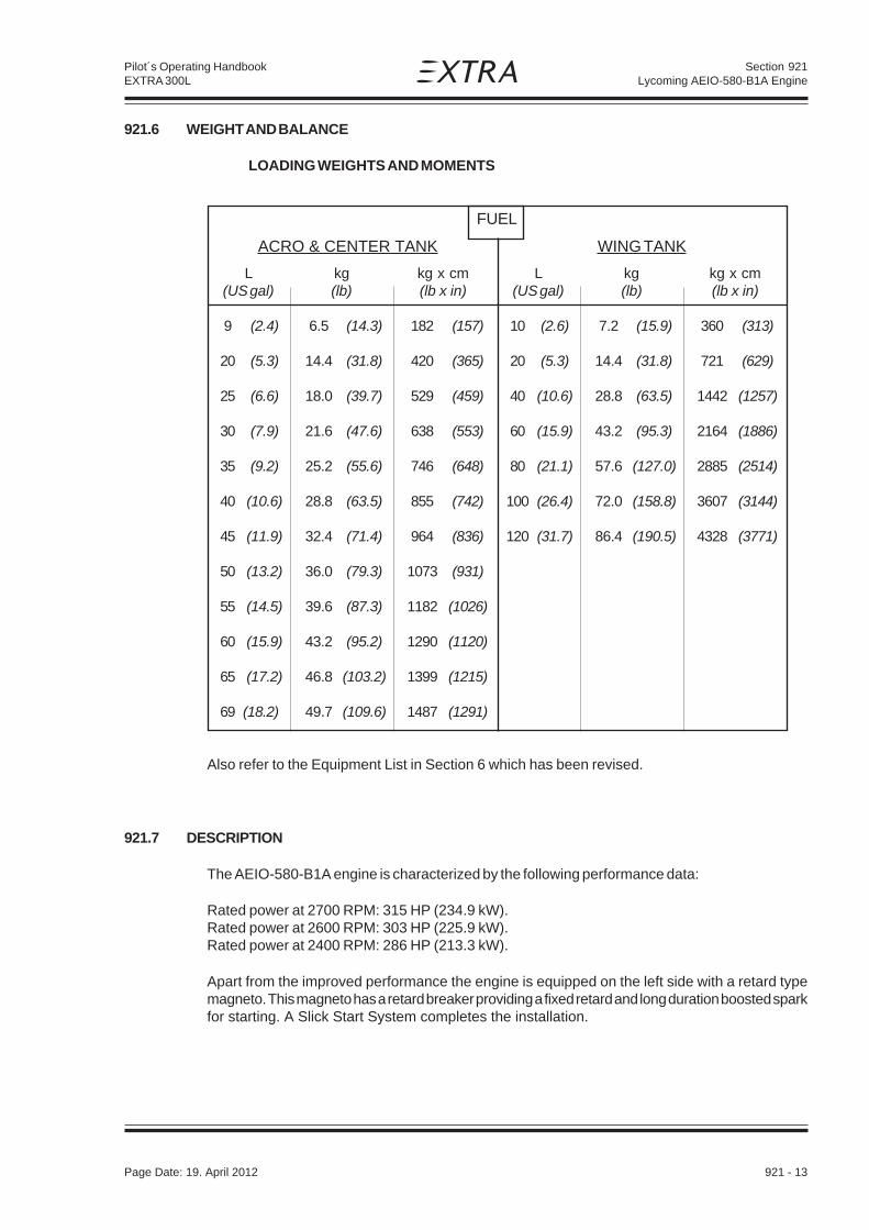
Page Date: 5. December 2008 921 - 13
Pilot´s Operating HandbookEXTRA 300L
Section 921Lycoming AEIO-580-B1A Engine
921.6 WEIGHT AND BALANCE
LOADING WEIGHTS AND MOMENTS
FUEL
ACRO & CENTER TANK WING TANK
L kg kg x cm L kg kg x cm(US gal) (lb) (lb x in) (US gal) (lb) (lb x in)
9 (2.4) 6.5 (14.3) 182 (157) 10 (2.6) 7.2 (15.9) 360 (313)
20 (5.3) 14.4 (31.8) 420 (365) 20 (5.3) 14.4 (31.8) 721 (629)
25 (6.6) 18.0 (39.7) 529 (459) 40 (10.6) 28.8 (63.5) 1442 (1257)
30 (7.9) 21.6 (47.6) 638 (553) 60 (15.9) 43.2 (95.3) 2164 (1886)
35 (9.2) 25.2 (55.6) 746 (648) 80 (21.1) 57.6 (127.0) 2885 (2514)
40 (10.6) 28.8 (63.5) 855 (742) 100 (26.4) 72.0 (158.8) 3607 (3144)
45 (11.9) 32.4 (71.4) 964 (836) 120 (31.7) 86.4 (190.5) 4328 (3771)
50 (13.2) 36.0 (79.3) 1073 (931)
55 (14.5) 39.6 (87.3) 1182 (1026)
60 (15.9) 43.2 (95.2) 1290 (1120)
65 (17.2) 46.8 (103.2) 1399 (1215)
69 (18.2) 49.7 (109.6) 1487 (1291)
Also refer to the Equipment List in Section 6 which has been revised.
921.7 DESCRIPTION
The AEIO-580-B1A engine is characterized by the following performance data:
Rated power at 2700 RPM: 315 HP (234.9 kW).Rated power at 2600 RPM: 303 HP (225.9 kW).Rated power at 2400 RPM: 286 HP (213.3 kW).
Apart from the improved performance the engine is equipped on the left side with a retard typemagneto. This magneto has a retard breaker providing a fixed retard and long duration boosted sparkfor starting. A Slick Start System completes the installation.
Page Date: 19. April 2012

921 - 14 Page Date: 5. December 2008
Pilot´s Operating HandbookEXTRA 300L
Section 921Lycoming AEIO-580-B1A Engine
Figure 921-1, Center Tank Versions
Page Date: 19. April 2012

Page Date: 5. December 2008 921 - 15
Pilot´s Operating HandbookEXTRA 300L
Section 921Lycoming AEIO-580-B1A Engine
Figure 921-1 shows both fuselage fuel tank configurations which are available for the EXTRA 300Lex factory. Item 6 shows the contour of the center tank with 42 L (11.1 US gal) capacity(configuration 1). Item 7 shows the contour of the center tank with 60 L (15.9 US gal) capacity(configuration 2). In each configuration the center tanks are located above the acro tank (1) having9 L (2.4 US gal) fuel quantity. They are installed in the same place and in the same manner. Thisincludes the vent line (2) and the fuel filler (5) location. However the steel tubes of the fuselagecarrying the 60 L tank and its mounting have been reinforced. The configuration 1 fuel quantity probe(3) is located in front of the fuel filler (5), the configuration 2 probe (4) is located behind. The fuelquantity indicators are identical in both configurations.
Page Date: 19. April 2012

921 - 16 Page Date: 5. December 2008
Pilot´s Operating HandbookEXTRA 300L
Section 921Lycoming AEIO-580-B1A Engine
Page Date: 19. April 2012
Left blank intentionally

Section 922Center Tank Increased Capacity
Page Date: 5. December 2008 922 - 1
Pilot´s Operating HandbookEXTRA 300L
SECTION 922
CENTER TANK INCREASED CAPACITY
Table of Contents
Paragraph PageSECTION 922
922.1 GENERAL.........................................................................................................................922-3
922.2 LIMITATIONS ...................................................................................................................922-3922.2.1 Fuel .................................................................................................................................. 922-3922.2.2 Weight Limits ................................................................................................................... 922-3922.2.3 Placards ...........................................................................................................................922-3
922.3 EMERGENCY PROCEDURES...........................................................................................922-3
922.4 NORMAL PROCEDURES .................................................................................................922-3
922.5 PERFORMANCE ..............................................................................................................922-4922.5.1 Cruise Performance ..........................................................................................................922-4922.5.2 Range ...............................................................................................................................922-5922.5.3 Endurance ........................................................................................................................922-6
922.6 WEIGHT AND BALANCE .................................................................................................922-7
922.7 DESCRIPTION OF THE SYSTEM ....................................................................................922-8
922.8 HANDLING, SERVICING AND MAINTENANCE ................................................................922-8

Section 922Center Tank Increased Capacity
922 - 2 Page Date: 5. December 2008
Pilot´s Operating HandbookEXTRA 300L
Left blank intentionally

Section 922Center Tank Increased Capacity
Page Date: 5. December 2008 922 - 3
Pilot´s Operating HandbookEXTRA 300L
922.1 GENERAL
The center fuel tank with an increased fuel capacity from 42 to 60 L is available ex factory forthe fuelage fuel tank system of the EXTRA 300L.
922.2 LIMITATIONS
The following data deviate from the data given in Section 2 of this Handbook:
922.2.1 FuelTotal fuel capacity: 189 L (49.9 US gal)Usable fuel capacity in the system: 187 L (49.4 US gal)Acro & center tank capacity: 69 L (18.2 US gal)Usable fuel capacity for acrobatic: 67 L (17.7 US gal)
922.2.2 Weight LimitsMax. allowed empty weight Normal category: 729 kg (1607 lb)
Acrobatic category I: 686 kg (1512 lb)
922.2.3 PlacardsThe following placards replace the existing placards:
(in both cockpitsnear selector valve handle)
(On the rear instrument panelnext to the fuel quantity indicator)
922.3 EMERGENCY PROCEDURES
Not affected.
922.4 NORMAL PROCEDURES
Not affected
FUEL SELECTOR VALVE
CENTER +ACROTANKusable 45,5 L (12,0 US GAL)
OFF
WING TANKSusable 154 L(40,7 US GAL)
CENTER TANK INDICATIONSHOWS "ZERO" IN LEVEL FLIGHT
BELOW 9 L (2.4 US GAL).UNUSABLE FUEL 2 L (0.5 US GAL)
FUEL SELECTOR VALVEWING TANKS
usable 120 L (31.7 US GAL)
OFF
CENTER(ACRO)TANK
usable 67 L(17.7 US GAL)

Section 922Center Tank Increased Capacity
922 - 4 Page Date: 5. December 2008
Pilot´s Operating HandbookEXTRA 300L
922.5 PERFORMANCE
922.5.1 Cruise PerformanceRange and Endurance values for a T/O Weight of 950 kg (2095 lb) including fuel for warm-upand Take-Off from SL, max. cont. Power climb to cruising altitude, and a reserve of 21 L(5.55 gal) for 45 minutes with 45% Power. 2 L (0.53 gal) unusable fuel is taken into account.(At ISA - Conditions.)
PA Eng. Manif. Power Setting Fuel TAS IAS Endur. Range MixturePress. Consumption 1* 1* 2*
[ft] (m) [rpm] [inHg] [%] [hp] [L/h] [gal/h] [kts] (km/h) [kts] (km/h) [h] [nm] (km) Best ...
2000 2700 27.4 95 286 88.2 (23.3) 182.6 (338) 173 (320) 1.73 317 (587) Power(610) 2400 25.1 75 225 68.7 (18.2) 167.6 (310) 160 (296) 2.22 372 (689) Power
2200 24.2 65 195 50.5 (13.3) 159.3 (295) 152 (282) 3.03 481 (891) Economy2000 23.5 55 165 42.6 (11.3) 150.2 (278) 144 (267) 3.58 538 (996) Economy2000 20.2 45 135 36.5 (9.6) 139.9 (259) 134 (248) 4.18 584 (1082) Economy
4000 2700 25.4 89 267 82.7 (21.8) 181.5 (336) 168 (311) 1.85 333 (617) Power(1219) 2400 24.6 75 225 68.7 (18.2) 170.9 (317) 158 (293) 2.22 377 (698) Power
2200 23.7 65 195 50.5 (13.3) 162.4 (301) 150 (278) 3.02 487 (902) Economy2000 23.0 55 165 42.6 (11.3) 153.1 (284) 142 (263) 3.56 544 (1007) Economy2000 19.7 45 135 36.5 (9.6) 142.6 (264) 133 (246) 4.18 591 (1095) Economy
6000 2700 23.6 83 248 77.6 (20.5) 180.5 (334) 162 (300) 1.97 351 (650) Power(1829) 2500 23.3 75 225 69.8 (18.4) 174.3 (323) 158 (293) 2.19 377 (698) Power
2200 23.2 65 195 50.5 (13.3) 165.6 (307) 149 (276) 3.00 493 (913) Economy2000 22.5 55 165 42.6 (11.3) 156.1 (289) 141 (261) 3.54 531 (983) Economy2000 19.3 45 135 36.5 (9.6) 145.4 (269) 131 (243) 4.12 598 (1107) Economy
8000 2700 21.8 77 231 73.4 (19.4) 179.5 (332) 156 (289) 2.08 367 (680) Power(2438) 2675 21.5 75 225 71.9 (19.0) 177.8 (329) 155 (287) 2.12 371 (687) Power
2350 21.5 65 195 52.0 (13.7) 169.0 (313) 147 (272) 2.90 485 (898) Economy2050 21.4 55 165 43.0 (11.4) 159.3 (295) 139 (257) 3.49 552 (1022) Economy2000 18.8 45 135 36.5 (9.6) 148.4 (275) 130 (241) 4.10 604 (1119) Economy
10000 2700 20.2 72 215 69.6 (18.4) 178.5 (331) 151 (280) 2.19 382 (707) Power(3048) 2500 19.9 65 195 53.6 (14.2) 172.4 (319) 148 (274) 2.81 476 (882) Economy
2150 19.9 55 165 43.7 (11.5) 162.5 (301) 138 (256) 3.42 549 (1017) Economy2000 18.4 45 135 36.5 (9.6) 151.4 (280) 129 (239) 4.07 611 (1132) Economy
12000 2700 18.6 67 200 66.2 (17.5) 177.5 (329) 146 (270) 2.28 396 (733) Power(3658) 2675 18.4 65 195 55.3 (14.9) 176.0 (326) 144 (267) 2.71 467 (865) Economy
2300 18.3 55 165 45.2 (11.9) 165.9 (307) 136 (252) 3.29 537 (995) Economy2000 17.9 45 135 36.5 (9.6) 154.5 (286) 127 (235) 4.03 617 (1143) Economy
14000 2700 17.2 62 186 63.0 (16.6) 176.6 (327) 140 (259) 2.42 410 (759) Power(4267) 2450 17.0 55 165 46.7 (12.3) 169.4 (314) 135 (250) 3.17 524 (970) Economy
2075 17.7 45 135 37.1 (9.8) 157.8 (292) 122 (226) 3.94 611 (1132) Economy
N O T E
1* For temperatures above/ below Standard (ISA), increase/decrease Range 1,7% andEndurance 1,1% for each 10°C (18°F) above/below Standard Day Temperature forparticular altitude.
2* Leaning with exhaust gas temperature (EGT) gage:For the adjustment "Best Power", first lean the mixture to achieve the top exhausttemperature (peak EGT) and then enrich again until the exhaust temperature is 100°Flower than peak EGT.For the adjustment "Best Economy", simply lean the mixture to achieve the topexhaust temperature (peak EGT).
W A R N I N G
Risk of engine overheating.Always return the mixture to full rich before increasing power settings.
Page Date: 16. March 2009Page Date: 20. January 2016
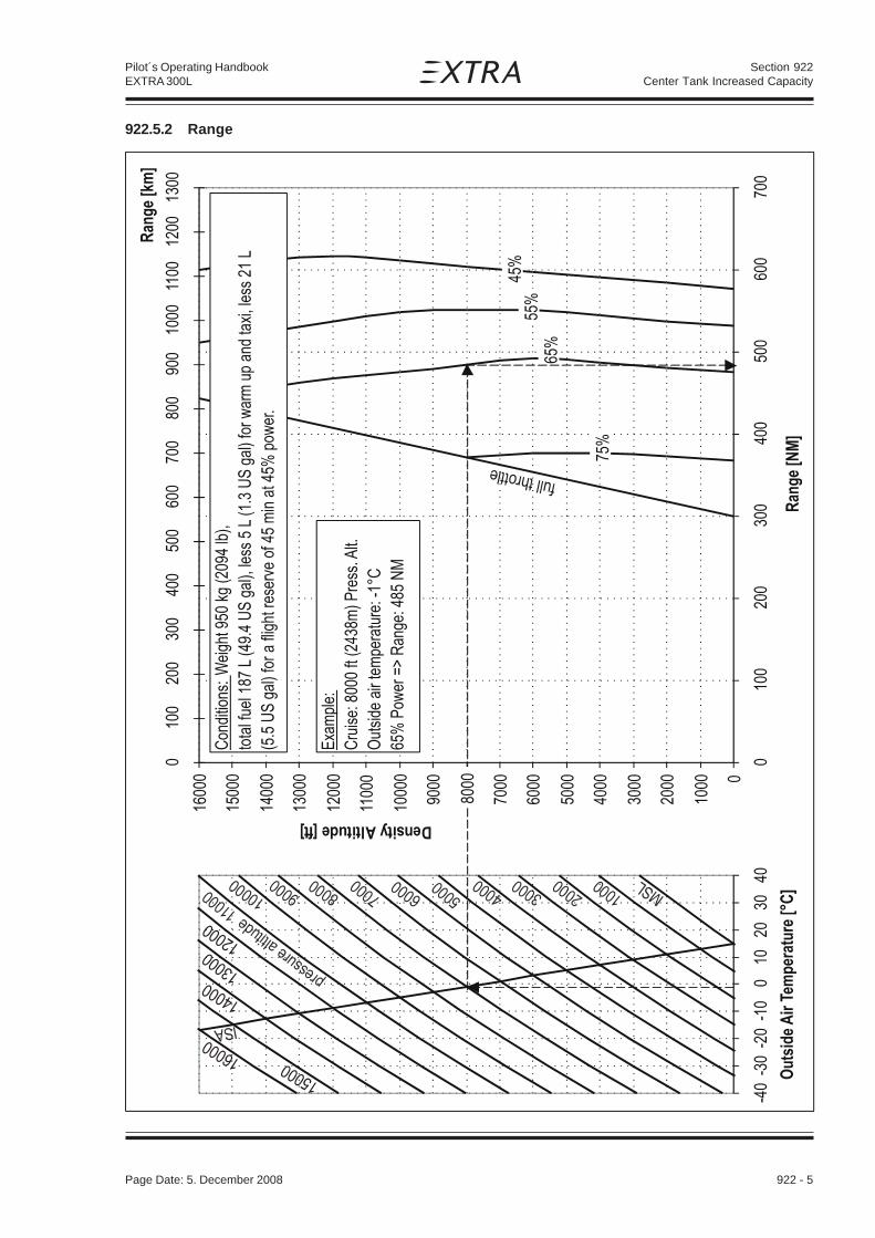
Section 922Center Tank Increased Capacity
Page Date: 5. December 2008 922 - 5
Pilot´s Operating HandbookEXTRA 300L
922.5.2 Range

Section 922Center Tank Increased Capacity
922 - 6 Page Date: 5. December 2008
Pilot´s Operating HandbookEXTRA 300L
922.5.3 Endurance

Section 922Center Tank Increased Capacity
Page Date: 5. December 2008 922 - 7
Pilot´s Operating HandbookEXTRA 300L
922.6 WEIGHT AND BALANCE
LOADING WEIGHTS AND MOMENTS
TOTAL FUEL CAPACITY: 189 L (49.9 US gal)
FUEL
ACRO & CENTER TANK WING TANK
L kg kg x cm L kg kg x cm(US gal) (lb) (lb x in) (US gal) (lb) (lb x in)
9 (2.4) 6.5 (14.3) 182 (157) 10 (2.6) 7.2 (15.9) 360 (313)
20 (5.3) 14.4 (31.8) 420 (365) 20 (5.3) 14.4 (31.8) 721 (629)
25 (6.6) 18.0 (39.7) 529 (459) 40 (10.6) 28.8 (63.5) 1442 (1257)
30 (7.9) 21.6 (47.6) 638 (553) 60 (15.9) 43.2 (95.3) 2164 (1886)
35 (9.2) 25.2 (55.6) 746 (648) 80 (21.1) 57.6 (127.0) 2885 (2514)
40 (10.6) 28.8 (63.5) 855 (742) 100 (26.4) 72.0 (158.8) 3607 (3144)
45 (11.9) 32.4 (71.4) 964 (836) 120 (31.7) 86.4 (190.5) 4328 (3771)
50 (13.2) 36.0 (79.3) 1073 (931)
55 (14.5) 39.6 (87.3) 1182 (1026)
60 (15.9) 43.2 (95.2) 1290 (1120)
65 (17.2) 46.8 (103.2) 1399 (1215)
69 (18.2) 49.7 (109.6) 1487 (1291)

Section 922Center Tank Increased Capacity
922 - 8 Page Date: 5. December 2008
Pilot´s Operating HandbookEXTRA 300L
922.7 DESCRIPTION OF THE SYSTEM
(Refer to Figure 922-1) The center fuel tank (5) with increased fuel capacity is installed in thesame place and in the same manner as the standard fuel center tank. This includes the ventline (2) and the fuel filler (3) location. However the tank is increased in down- and rearwarddirection. The steel tubes of the fuselage carrying the tank and the tank mounting arereinforced. The fuel contents probe (4) has been changed while the indicator is still the same.The total fuel capacity of the center tank is 60 L (15.9 US gal). The total fuel capacity of theacro tank (1) is 9 L (2.4 US gal). The usable fuel quantity of both center and acro tank is 67 L(17.7 US gal).
922.8 HANDLING, SERVICING AND MAINTENANCE
Not affected.
Figure 922-1, Center Tank and Environment

Section 923GARMIN GTX 328 Transponder
Page Date: 5. December 2008 923 - 1
Pilot´s Operating HandbookEXTRA 300L
SECTION 923
GARMIN GTX 328 TRANSPONDER
Table of Contents
Paragraph PageSECTION 923 GARMIN GTX 328 TRANSPONDER
923.1 GENERAL.........................................................................................................................923-3923.1.1 Mode Selection Keys ........................................................................................................923-4923.1.2 Code Selection .................................................................................................................923-4923.1.3 Keys for other GTX 328 Functions .....................................................................................923-5923.1.4 Function Display ...............................................................................................................923-5923.1.5 Configuration Mode ...........................................................................................................923-6923.1.6 Altitude trend indicator ...................................................................................................... 923-6923.1.7 Failure Annunciation ..........................................................................................................923-6
923.2 LIMITATIONS ...................................................................................................................923-7
923.3 EMERGENCY PROCEDURES...........................................................................................923-7923.3.1 Important Codes ...............................................................................................................923-7
923.4 NORMAL PROCEDURES .................................................................................................923-7
923.5 PERFORMANCE ..............................................................................................................923-7

Section 923GARMIN GTX 328 Transponder
923 - 2 Page Date: 5. December 2008
Pilot´s Operating HandbookEXTRA 300L
Left blank intentionally

Section 923GARMIN GTX 328 Transponder
Page Date: 5. December 2008 923 - 3
Pilot´s Operating HandbookEXTRA 300L
923.1 GENERAL
The Garmin GTX 328 panel mounted Mode S VFR Transponder is a radio transmitter and receiverthat fulfills the role of the airborne beacon equipment according to the requirements of the Air TrafficRadar Beacon System (ATCRBS). Its functionality includes replying to ATCRBS Mode A and Cand Mode S interrogations. The Mode S function will allow the ground station to individually selectthe aircraft by its Aircraft Address assigned to the aircraft by the aviation agency.
It operates on radar frequencies, receiving ground radar interrogations at 1030 MHz and transmittinga coded response of pulses to ground-based radar on a frequency of 1090 MHz. The GTX 328 isequipped with IDENT capability that activates the Special Position Identification (SPI) pulse for 18seconds. Mode S transmit/receive capability also requires 1090 MHz transmitting and1030 MHzreceiving for Mode S functions.
In addition to displaying the code, reply symbol and mode of operation, the GTX 328 screen willdisplay pressure altitude and timer functions. The displayed pressure altitude may not agree withthe aircraft’s baro-corrected altitude under non standard conditions. The unit also features flighttimers.
The Traffic Information Service (TIS) is not available in this installation.
N O T E
The GTX 328 owner accepts all responsibility for obtaining the proper license beforeusing the transponder.
The coverage you can expect from the GTX 328 is limited to „line of sight“. Low altitude or aircraftantenna shielding by the aircraft itself may result in reduced range. Range can be improved byclimbing to a higher altitude. It may be possible to minimize antenna shielding by locating theantenna where dead spots are only noticed during abnormal flight attitudes.
N O T I C E
Damage possible due to current peaks.The GTX 328 should be turned off before starting or shutting down aircraft engine.
The GTX 328 Transponder is automatically powered on by the respective AVIONIC MASTER switchor when previously manually powered off while AVIONIC MASTER switch is on by pressing theSTBY, ALT or ON keys. After power on, a start-up page will be displayed while the unit performsa self test.
This supplement is written for software version 5.00 or later, and is not suitable for earlier softwareversions. Some differences in operation may be observed when comparing the information in thissupplement to later software versions.
Verify the information herein with the GTX 328 pilot's guide (PN 190-00420-03 applicable revision)you received with your transponder. There you find also further information.
Page Date: 5. December 2008Page Date: 20. January 2016

Section 923GARMIN GTX 328 Transponder
923 - 4 Page Date: 5. December 2008
Pilot´s Operating HandbookEXTRA 300L
923.1.1 MODE SELECTION KEYS
OFFPowers off the GTX 328. Pressing STBY, ON or ALT Key powers on the transponder displaying thelast active identification code.
STBYSelects the standby mode. When in standby mode, the transponder will not reply to any inter-rogations.
ONSelects Mode A. In this mode the transponder replies to interrogations, as indicated by the ReplySymbol. Replies do not include altitude information.
ALTSelects Mode A and Mode C. In ALT mode, the transponder replies to identification and altitudeinterrogations as indicated by the Reply Symbol. Replies to altitude interrogations include thestandard pressure altitude received from an external altitude source, which is not adjusted forbarometric pressure. Any time the function ON or ALT is selected the transponder becomes anactive part of the Air Traffic Control Radar Beacon System (ATCRBS). The transponder alsoresponds to interrogations from TCAS equipped aircraft.
923.1.2 CODE SELECTION
Code selection is done with eight keys (0 – 7) providing 4,096 active identification codes. Pushingone of these keys begins the code selection sequence. Digits that are not yet entered appear asdashes. The new code is activated when the fourth digit is entered. Pressing the CLR Key movesthe cursor back to the previous digit. Pressing the CLR Key when the cursor is on the first digit ofthe code, or pressing the CRSR Key during code entry, removes the cursor and cancels data entry,restoring the previous code. Press the CLR Key up to five seconds after code entry is completeto return the cursor to the fourth digit. The numbers 8 and 9 are not used for code entry, only forentering a Count Down time, and contrast and display brightness.
IMPORTANT CODES:
1200 The VFR code for any altitude in the US (Refer to ICAO standards elsewhere)
7000 The VFR code commonly used in Europe (Refer to ICAO standards)
7500 Hijack code (Aircraft is subject to unlawful interference)
7600 Loss of communications
7700 Emergency
7777 Military interceptor operations (Never squawk this code)
0000 Military use (Not enterable)
Page Date: 5. December 2008

Section 923GARMIN GTX 328 Transponder
Page Date: 5. December 2008 923 - 5
Pilot´s Operating HandbookEXTRA 300L
Avoid selecting codes 0000, 7500, and all codes in the 7600-7777 range. These codes triggerspecial indicators in automated facilities. An aircraft’s transponder code is used for ATC trackingpurposes, therefore exercise care when making routine code changes!
923.1.3 KEYS FOR OTHER GTX 328 FUNCTIONS
IDENTPressing the IDENT Key activates the Special Position Identification (SPI) Pulse for 18 seconds,identifying your transponder return from others on the air traffic controller’s screen. The word‘IDENT’ will appear in the upper left corner of the display while the IDENT mode is active.
VFRSets the transponder code to the pre-programmed VFR code selected in Configuration Mode (thisis set to 7000 at the factory). Pressing the VFR Key again restores the previous identification code.
FUNCChanges the page shown on the right side of the display. Display data includes Pressure Altitude,Flight Time, Count Up and Count Down timers. Also displays Contrast and Display (if manualcontrol and backlighting is selected in the installation configuration).
START/STOPStarts and stops the Count Up, Count Down and Flight timers.
CRSRInitiates starting time entry for the Count Down timer and cancels transponder code entry.
CLRResets the Count Up, Count Down and Flight timers. Cancels the previous keypress during codeselection and Count Down entry. Returns cursor to the fourth code digit within five seconds afterentry.
8Reduces Contrast and Display Brightness when the respective fields are displayed (if manualcontrol is selected in the installation configuration) and enters the number eight into the Count Downtimer.
9Increases Contrast and Display Brightness when the respective fields are displayed (if manualcontrol is selected in the installation configuration) and enters the number nine into the Count Downtimer.
923.1.4 FUNCTION DISPLAY
'PRESSURE ALT'Displays the altitude data supplied to the GTX 328 in feet, hundreds of feet (i.e., flight level), ormeters, (dependent upon installation configuration).
'FLIGHT TIME'Timer start is configured as either Manual or Automatic. When Manual, displays the Flight Time,controlled by the START/STOP and CLR keys. When Automatic, the timer begins when take offis sensed.

Section 923GARMIN GTX 328 Transponder
923 - 6 Page Date: 5. December 2008
Pilot´s Operating HandbookEXTRA 300L
'ALTITUDE MONITOR'The ALTITUDE MONITOR function is not available in this installation.
'OAT/DALT'The OAT/DALT function is not available in this installation (no temperature input).
'COUNT UP TIMER'Controlled by the START/STOP and CLR keys. Pressing the CLR key zeros the display.
'COUNT DOWN TIMER'Controlled by START/STOP, CLR, and CRSR keys. The initial Count Down time is entered withthe 0 - 9 keys. Pressing the CLR key resets the timer to the initial value.
'STBY'The transponder will not reply to any interrogations.
'GND'This page is not active.
'CONTRAST'This page is only displayed if manual contrast mode is selected during installation configuration.Contrast is controlled by the 8 and 9 keys.
'DISPLAY'This page is only displayed if manual backlighting mode is selected during installation configuration.Backlighting is controlled by the 8 and 9 keys.
923.1.5 CONFIGURATION MODE
The configurartion mode is not active.
The GTX 328’s options are normally set at time of installation. To request any changes of the GTX328 parameters, contact an authorized Garmin Aviation Service Center.
923.1.6 ALTITUDE TREND INDICATOR
When the 'PRESSURE ALT' page is displayed, an arrow may be displayed to the right of thealtitude, indicating that the altitude is increasing or decreasing. One of two sizes of arrows may bedisplayed depending on the vertical speed rate. The sensitivity of these arrows is set by anauthorized Garmin Aviation Service Center.
923.1.7 FAILURE ANNUNCIATION
If the unit detects an internal failure, the screen displays 'FAIL'. When 'FAIL' is annunciated notransponder data is transmitted.
Page Date: 5. December 2008

Section 923GARMIN GTX 328 Transponder
Page Date: 5. December 2008 923 - 7
Pilot´s Operating HandbookEXTRA 300L
923.2 LIMITATIONS
Not applicable.
923.3 EMERGENCY PROCEDURES
923.3.1 IMPORTANT CODES
7600 Loss of communications.
7500 Hijacking.
7700 Emergency (All secondary surveillance radar sites are ready to receive this code at alltimes).
See the Airman’s Information Manual (AIM) for a detailed explanation of identification codes.
923.4 NORMAL PROCEDURES
Not applicable.
923.5 PERFORMANCE
Not applicable.

Section 923GARMIN GTX 328 Transponder
923 - 8 Page Date: 5. December 2008
Pilot´s Operating HandbookEXTRA 300L
Left blank intentionally

Section 924ASPEN EFD1000 PILOT PFD
Page Date: 31. March 2009 924 - 1
Pilot´s Operating HandbookEXTRA 300L
SECTION 924
ASPEN EFD1000 PILOT PFD
Table of Contents
Paragraph PageSECTION 924 ASPEN EFD1000 PILOT PFD
924.1 GENERAL.........................................................................................................................924-3
924.2 LIMITATIONS ...................................................................................................................924-3924.2.1 Placards and Decals ......................................................................................................... 924-3
924.3 EMERGENCY PROCEDURES...........................................................................................924-4
924.4 NORMAL PROCEDURES .................................................................................................924-4
924.5 PERFORMANCE ..............................................................................................................924-4
924.6 WEIGHT & CENTER OF GRAVITY ...................................................................................924-4
924.7 SYSTEM DESCRIPTION ..................................................................................................924-4924.7.1 General ............................................................................................................................. 924-4924.7.2 Pilot Controls Overview......................................................................................................924-5924.7.3 Power Control ...................................................................................................................924-5924.7.4 Display Screen and Control Layout ...................................................................................924-6924.7.5 Control Knobs ...................................................................................................................924-7924.7.6 Setting Flight Instruments .................................................................................................924-7924.7.7 Knob Sync Function .........................................................................................................924-8924.7.8 Hot Key Operation ............................................................................................................ 924-8924.7.9 Back Light Control ............................................................................................................ 924-9924.7.10 Map Range Control ......................................................................................................... 924-10924.7.11 Display Reversion Control and Abnormal Shutdown ......................................................... 924-10924.7.12 Warning, Caution, and Advisory Summary ...................................................................... 924-10924.7.13 Main Menu Operation ...................................................................................................... 924-11
924.8 HANDLING, SERVICING AND MAINTENANCE .............................................................. 924-12

Section 924ASPEN EFD1000 PILOT PFD
924 - 2 Page Date: 31. March 2009
Pilot´s Operating HandbookEXTRA 300L
Left blank intentionally

Section 924ASPEN EFD1000 PILOT PFD
Page Date: 31. March 2009 924 - 3
Pilot´s Operating HandbookEXTRA 300L
924.1 GENERAL
The Aspen Avionics’ EFD1000 PILOT PFD is a panel-mounted Electronic Flight Instrument System(EFIS) that presents the pilot with displays of attitude, altitude, indicated airspeed, heading, rateof turn, and slip/skid information. The system also displays supplemental flight data such as winds,TAS, OAT, etc. (see Item 36 - 39 of Figure 1), pilot-selectable indices („bugs“), and variousannunciations that increase situational awareness and enhance flight safety. Moving maps are alsodisplayed when an external GPS is installed and connected to the EFD1000 PILOT PFD. In theEXTRA 300L the EFD1000 PILOT PFD is used as a secondary (back-up) instrument system.
N O T E
Due to the capabilities of the aircraft - especially the extreme agility with high angularrates - the EFD1000 PILOT PFD cannot be operated reliably in acrobatics. Observeflags and reset EFD1000 PILOT PFD if required.
The EFD1000 PILOT PFD system components include the EFD1000 display head, a RemoteSensor Module (RSM), and a Configuration Module (CM). The RSM is installed in the aircraft tailunder the main fuselage cover.
N O T E
Due to the location of the RSM the outside air temperature data is available time-delayed.
The EFD1000 PILOT PFD model does not support display of navigation data from panel-mountedGPS navigators, VOR/Localizer radios, etc. See Section 924.7 of this Aircraft Flight ManualSupplement for a description of the operation of the EFD1000 PILOT PFD System.
The EFD1000 PILOT PFD System must utilize the software version described below or laterapproved versions. The system software version for the Main Application Processor (MAP) and forthe Input-Output Processor (IOP), both of which are contained within the EFD display head, isdisplayed via the Main Menu SYSTEM STATUS page.
This supplement is written for IOP SOFTWARE RELEASE 1.1, and is not suitable for earliersoftware versions. This software version corresponds to the ASPEN Airplane Flight ManualSupplement (Doc. A-01-179-00 Revision C). Some differences in operation may be observed whencomparing the information in this supplement to later software versions. Verify the informationherein with the EFD1000 PILOT PFD Pilot's Guide (Doc. A-01-184-00 applicable Revision) youreceived with your unit. There you find also further information.
924.2 LIMITATIONS
The functionality of the EFD1000 PILOT PFD may be used for VFR navigation purposes only whena reversion to traditional navigation (map, magnetic compass) is possible at any time.
924.2.1 PLACARDS AND DECALS
(Next to the EFD1000 PILOT PFD circuit breaker)
(above the EFD display head)
PFD
For situational awareness only
Page Date: 20. January 2016

Section 924ASPEN EFD1000 PILOT PFD
924 - 4 Page Date: 31. March 2009
Pilot´s Operating HandbookEXTRA 300L
The following electronic placard is provided on the EFD1000 PILOT PFD display whenever the RSMGPS is providing position data for the basemap display:
„RSM GPS REVERSION EMER USE ONLY“
924.3 EMERGENCY PROCEDURES
Not affected due to the use as a secondary instrument.
924.4 NORMAL PROCEDURES
Not affected due to the use as a secondary instrument.
924.5 PERFORMANCE
Not affected.
924.6 WEIGHT & CENTER OF GRAVITY
Refer to the equipment list in Section 6 of this Handbook.
924.7 SYSTEM DESCRIPTION
924.7.1 GENERAL
The EFD1000 PILOT PFD system is a flat-panel LCD flight instrument that presents the pilot withdisplays of attitude, airspeed, altitude, vertical speed, slaved compass, slip/skid, and rate of turninformation. The display head incorporates a solid-state Air Data and Attitude Heading ReferenceSystem (ADAHRS) to provide data for the flight instruments. The ADAHRS system uses data fromits internal solid state rate gyros and accelerometers, pitot and static sensors, solid statemagnetometer, and solid state temperature probes, all contained within the display head and RSM,to derive the aircraft attitude and air data solutions.
N O T E
Although intuitive, a reasonable degree of familiarity is required to use the EFD1000PILOT PFD.

Section 924ASPEN EFD1000 PILOT PFD
Page Date: 31. March 2009 924 - 5
Pilot´s Operating HandbookEXTRA 300L
924.7.2 PILOT CONTROLS OVERVIEW
Pilot interaction with the EFD1000 PILOT PFD is accomplished through two knobs with push/rotatefunction and 11 buttons located on the display bezel. Refer to Figure 2. Two control knobs are usedto control pilot settable bugs and references. Three lower push buttons, located between the controlknobs, are not used in the EFD1000 PILOT PFD model. Three dedicated buttons on the upper sideof the right bezel control map range, display reversion, and provide access to the main menu. Upto five soft keys on the lower half of the right bezel control frequently used commands. These fivekeys are also used when navigating the main menu.
924.7.3 POWER CONTROL
To enhance safety, the EFD1000 PILOT PFD includes an internal battery that allows the systemto continue to operate in the event of a failure of the aircraft electrical system. This ensures thatthe EFD1000 PILOT PFD flight instrument continues to remain available for a period of time followingthe loss of all external supply power. This internal battery is not required by regulation; however,it is good practice to verify the status of the battery prior to takeoff. The EFD1000 PILOT PFDreceives aircraft power from the battery bus via the PFD circuit breaker. Whenever indicatedairspeed is invalid or below 30 KIAS the EFD1000 PILOT PFD will power up and power down withthe application or removal of external power. To turn on the system, turn on the AVIONIC switch(when Battery Master is ON). Turning off the system is vice versa. A message is presented duringthe normal power down sequence to enable the pilot to abort the shutdown and switch to internalbattery.
The AHRS will perform an internal test during EFD1000 PILOT PFD power up. The aircraft shouldremain stationary during the AHRS power up and alignment sequence. If the aircraft is moved duringAHRS alignment it will take longer for accurate attitude and heading information to be presentedto the pilot. Attitude and heading information is presented once the AHRS completes the alignmentprocess.
When IAS is greater than 30 KIAS and the input voltage is below 12.5 ± 0.3 V the EFD willautomatically switch to its internal battery (e.g. aircraft charging system failure). The EFD1000PILOT PFD internal battery will provide at least 30 minutes of power when it is fully charged. Thebattery provides power to the display head and the RSM with the emergency GPS. Reducing thebacklight intensity will extend the battery operating time.
Battery charge status may be viewed from the „Power Settings“ page of the Main Menu (See Section924.7.13 for more information).
N O T E S:
As a protection mechanism, the EFD1000 PILOT PFD internal battery may not chargewhen the battery temperature is at extreme high or low temperatures. This situationmay occur when the battery was being used and system power is subsequentlyrestored, or it may occur under high or low ambient temperatures.
If operation from the internal battery occurs during night and/or IFR operations, oneshould land as soon as possible, even if external power is restored, as the battery willnot recharge following restoration of external power until the battery temperature hasreturned to normal.
A unit operating from battery may be powered off using the „Shut Down“ command available in thePower Settings Menu.

Section 924ASPEN EFD1000 PILOT PFD
924 - 6 Page Date: 31. March 2009
Pilot´s Operating HandbookEXTRA 300L
In the unlikely event that the normal power control is not working, the EFD1000 PILOT PFD maybe forced to shut down by first pulling the PFD circuit breaker and then pressing and holding theREV button for at least 5 seconds.
924.7.4 DISPLAY SCREEN AND CONTROL LAYOUT
1) Reversion Control2) Range Control3) Menu Control4) „TPS“ Tapes ON/OFF Control5) "Minimum" indication ON/OFF Control6) „360/ARC“ HSI View Control7) „MAP“ ON/OFF logic Control8) Not Used9) Right Control Knob10) Left Control Knob11) Not Used12) Not Used13) Not Used14) Micro SD Card slot15) Automatic Dimming Photocell16) Attitude Indicator17) Aircraft Symbol19) Roll Pointer20) Slip / Skid Indicator21) Airspeed Indicator Tape22) Selected Airspeed Field23) Airspeed Drum/Pointer24) Altitude Alert25) Selected Altitude Field26) Altitude Drum/Pointer27) Altitude Tape34) True Airspeed35) Barometric Pressure Setting Field36) Ground Speed37) OAT38) Wind Direction Arrow39) Wind Direction and Speed36 - 39) Data Bar40) Selected Source Information Field42) Selected Heading Field43) Vertical Speed Digital Value44) Vertical Speed Tape45) Left Control Knob state46) Right Control Knob state52) Magnetic Heading53) Compass Scale54) Hot Key legend58) Heading Bug59) Airspeed Bug60) Altitude Bug
Figure 1 - PFD Display Features

Section 924ASPEN EFD1000 PILOT PFD
Page Date: 31. March 2009 924 - 7
Pilot´s Operating HandbookEXTRA 300L
924.7.5 CONTROL KNOBS
GeneralTwo control knobs on the EFD bezel are used to adjust pilot editable data fields. The left knobadjusts data fields on the left side of the display, and the right knob adjusts data fields on the rightside of the display.
The knob logic includes active and inactive states to prevent inadvertent adjustment of editablefields. After 10 seconds of inactivity, the knob returns to an inactive state and also returns to the„home“ state defined for that knob. A single push activates an inactive knob. Pushing the knob againwill advance the knob to the next editable field (if applicable) in a round-robin sequence.
When inactive, the knob legend is rendered in cyan. Once activated, the knob legend andassociated data field and bug (where appropriate) are rendered in magenta.
Left control knobThe left control knob adjusts the Indicated Airspeed Bug „IAS“ editable fields and the Course "CRS"(refer to Aspen Pilot's Guide for more information).
The home state for the left knob is „CRS“.
Right control knobThe right control knob controls Heading Bug „HDG“, Altitude Bug „ALT“, and Barometric PressureSetting „BARO“ editable fields in that order.
The home state for the right knob is „HDG.“
924.7.6 SETTING FLIGHT INSTRUMENTS
The following procedures are used to adjust pilot-editable data on the EFD1000 PILOT PFD:
Heading Bug SetTo set the heading bug, repeatedly PUSH the right control knob until the HDG field is enabled forediting. ROTATE the knob to the desired setting.
Altitude Bug SetTo set the altitude bug, repeatedly PUSH the right control knob until the ALT field is enabled forediting. ROTATE the knob to the desired setting
Barometric Pressure SetTo set the barometric pressure, repeatedly PUSH the right control knob until the BARO field isenabled for editing. ROTATE the knob to the desired setting.
N O T E
Cross check the barometric pressure setting against the primary altimeter whenever thevalue is adjusted on the EFD1000 PILOT PFD.
Course SetTo set the course, repeatedly PUSH the left control knob until the CRS field is enabled for editing.ROTATE the knob to the desired setting.

Section 924ASPEN EFD1000 PILOT PFD
924 - 8 Page Date: 31. March 2009
Pilot´s Operating HandbookEXTRA 300L
Indicated Airspeed Bug SetTo set the indicated airspeed bug, repeatedly PUSH the left control knob until the IAS field isenabled for editing. ROTATE the knob to the desired setting.
924.7.7 KNOB SYNC FUNCTION
Editable fields may be synchronized as a function of data type as described in Table 1 below.Whenever a control knob is held for approximately one second the active data type will be „sync’d“as follows:
Table 1 - Knob „Sync“ Operation
924.7.8 HOT KEY OPERATION
During normal operations, the five line select soft-keys on the lower right side of the display bezelare referred to as „Hot Keys.“ Hot Keys provide single-action access to frequently used functions.An electronic legend adjacent to each Hot Key indicates its hot key function. When the legend isgreen, the function is active. When it is gray, the function is inactive. The legend always annunciatesthe current state.
TAPES
Hot Key 1 enables/disables the display of the airspeed and altitude tapes.
MINIMUMS
Hot Key 2 enables/disables the display of the Minimums.

Section 924ASPEN EFD1000 PILOT PFD
Page Date: 31. March 2009 924 - 9
Pilot´s Operating HandbookEXTRA 300L
COMPASS PRESENTATION FORMAT
Hot Key 3 toggles the compass between a 360 rose display and a 100 deg ARC display.
BASEMAP AND DECLUTTER LEVEL
Hot Key 4 is used to enable the basemap and control the amount of basemap symbology that ispresented to the pilot. Each successive push of the MAP hot key will change the basemap declutterlevel in a round-robin sequence. Available selections are FP ONLY, and OFF.
The FP ONLY selection displays just the flight plan legs and waypoints associated with the GPSflight plan, and no other basemap features.
OFF removes all basemap and flight plan symbology.
GPS STEERING
Hot Key 5 enables/disables the GPS Steering.
924.7.9 BACK LIGHT CONTROL
The EFD1000 PILOT PFD includes an adjustable LCD backlight that provides both automatic andmanual brightness adjustments over a wide dimmable range. A single bezel-mounted photocellmeasures the ambient light, allowing an automatic dimming mode to be selected by the pilot.
Manual dimming control is enabled by the pilot to override the photocell input and adjust the displayto any desired intensity level (except off).
In either mode, the bezel-key backlighting is maintained at a fixed brightness level.
To adjust backlight intensity, press the MENU button and then press the left control knob to togglebetween auto (BRT AUTO) and manual brightness (BRT ADJUST) control.
To manually adjust the brightness, with BRT ADJUST displayed above the left knob rotate the knobuntil the desired brightness level is set. Valid brightness settings are 1 to 100.
On power up, the display defaults to AUTO brightness control.
When operating on the internal battery, backlight intensity setting is capped at a value of 70 for bothmanual and automatic operation.
Under extreme temperature conditions, such as may be encountered during ground operations onextremely hot days, the system backlight will automatically dim to an intensity of 30 wheneverinternal sensors determine that the system operating temperature has exceeded 70ºC. Should thisoccur the pilot should take steps to reduce the cockpit ambient temperature.
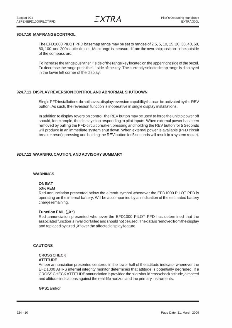
Section 924ASPEN EFD1000 PILOT PFD
924 - 10 Page Date: 31. March 2009
Pilot´s Operating HandbookEXTRA 300L
924.7.10 MAP RANGE CONTROL
The EFD1000 PILOT PFD basemap range may be set to ranges of 2.5, 5, 10, 15, 20, 30, 40, 60,80, 100, and 200 nautical miles. Map range is measured from the own ship position to the outsideof the compass arc.
To increase the range push the ‘+’ side of the range key located on the upper right side of the bezel.To decrease the range push the ‘–‘ side of the key. The currently selected map range is displayedin the lower left corner of the display.
924.7.11 DISPLAY REVERSION CONTROL AND ABNORMAL SHUTDOWN
Single PFD installations do not have a display reversion capability that can be activated by the REVbutton. As such, the reversion function is inoperative in single display installations.
In addition to display reversion control, the REV button may be used to force the unit to power offshould, for example, the display stop responding to pilot inputs. When external power has beenremoved by pulling the PFD circuit breaker, pressing and holding the REV button for 5 Secondswill produce in an immediate system shut down. When external power is available (PFD circuitbreaker reset), pressing and holding the REV button for 5 seconds will result in a system restart.
924.7.12 WARNING, CAUTION, AND ADVISORY SUMMARY
WARNINGS
ON BAT53% REMRed annunciation presented below the aircraft symbol whenever the EFD1000 PILOT PFD isoperating on the internal battery. Will be accompanied by an indication of the estimated batterycharge remaining.
Function FAIL („X“)Red annunciation presented whenever the EFD1000 PILOT PFD has determined that theassociated function is invalid or failed and should not be used. The data is removed from the displayand replaced by a red „X“ over the affected display feature.
CAUTIONS
CROSS CHECKATTITUDEAmber annunciation presented centered in the lower half of the attitude indicator whenever theEFD1000 AHRS internal integrity monitor determines that attitude is potentially degraded. If aCROSS CHECK ATTITUDE annunciation is provided the pilot should cross check attitude, airspeedand altitude indications against the real-life horizon and the primary instruments.
GPS1 and/or

Section 924ASPEN EFD1000 PILOT PFD
Page Date: 31. March 2009 924 - 11
Pilot´s Operating HandbookEXTRA 300L
RSM GPSAmber annunciation presented on the left edge of the display to indicate when a configured GPSflight plan and mapping data is invalid or not available.
RSM GPS REVERSIONEMER USE ONLYAmber annunciation presented on the bottom of the display whenever the EFD1000 PILOT PFDreverts to RSM GPS data and indicates that the RSM GPS is the current GPS source. RSM GPSusage is limited to „EMER(GENCY) USE ONLY“
ADVISORY
Altitude alerterAmber flag presented on the upper right corner of the display to indicate the aircraft is reaching(steady) or deviating (flashing) from the preselected altitude.
924.7.13 MAIN MENU OPERATION
MENU CONTROLS
The EFD1000 PILOT PFD Main menu is used to adjust various system configuration settings andpreferences. To select the Main Menu, press the MENU button on the right side of the display bezel.To leave the menu, press the MENU button again. Menu items are shown exclusively in the lowerhalf of the EFD1000 PILOT PFD display in the region below the data bar.
MAIN MENU NAVIGATION
Once the Main menu is activated, rotating the lower right control knob selects between the variousmenu pages. The current menu page is indicated by the page name and legend „page # of #“, andby the location of the green segment within the segmented menu navigation bar displayed at thebottom of the display
CONFIGURING MENU ITEMS
Each menu page shows a series of menu selections adjacent to the right bezel line select keys.Editable menu selections are indicated by white text, while status only or non-editable items areshown in green. Items that have been inhibited from editing are shown in gray.
Pressing a line select key adjacent to an editable field enables the item for editing, indicated byshowing the editable value in magenta. Rotating the lower right control knob adjusts the editablevalue. Changes are effective immediately.
To exit the edit mode press the adjacent line select key, press the right control knob, or leave themenu by pressing the MENU button.

Section 924ASPEN EFD1000 PILOT PFD
924 - 12 Page Date: 31. March 2009
Pilot´s Operating HandbookEXTRA 300L
MENU OPTIONS
General Settings PageFrom the GENERAL SETTINGS page the pilot may:
· Configure the barometric altimeter setting units to inches or millibars (in/mB)
· ENABLE or DISABLE the display of V-Speeds
· Perform an AHRS RESET.
V-Speed Setting PagesThis page is configured by EXTRA according to the speed values given in Section 4.0.1 of thisHandbook. Values can be changed by the pilot.
Power Settings PageThe POWER SETTINGS page is used to monitor and control the source of power to the EFD1000PILOT PFD, including overriding automatic power states. From the POWER SETTINGS Page thepilot may:
· Switch to Battery Power from External Power
· Switch to External Power from Battery Power
· Shut down or Re-Start the unit
· View the External Power Source Voltage
· View the Internal Battery Status
924.8 HANDLING, SERVICING AND MAINTENANCE
If the temperature sensor of the RSM is suspected to fail, it is advisable to initiate a check of theRSM vent hole. Consider that it is necessary to remove the aircraft tail fairing for that purpose.
Replace the internal battery every 3 years or 2200 hours.
Check unit and wiring each 100 hours or during annual inspection.
Refer to Aspen Document #A-01-126-00 latest revision for Instructions for Continued Airworthiness.
Page Date: 31. October 2013

Section 925GARMIN GNC 420W
Page Date: 31. March 2009 925 - 1
Pilot´s Operating HandbookEXTRA 300L
SECTION 925
GARMIN GNC 420W
Table of Contents
Paragraph PageSECTION 925 GARMIN GNC 420W
925.1 GENERAL.........................................................................................................................925-3925.1.1 GPS/WAAS TSO-C146a Class 3 Operation: .....................................................................925-3925.1.2 Class II Oceanic, Remote, and other Operations: ..............................................................925-3
925.2 LIMITATIONS ...................................................................................................................925-4925.2.1 Placards ...........................................................................................................................925-4
925.3 EMERGENCY/ABNORMAL PROCEDURES ......................................................................925-4925.3.1 Emergency Procedures ....................................................................................................925-4925.3.2 Abnormal Procedures .......................................................................................................925-4
925.4 NORMAL PROCEDURES .................................................................................................925-5
925.5 PERFORMANCE ..............................................................................................................925-5
925.6 WEIGHT & CENTER OF GRAVITY ...................................................................................925-6
925.7 SYSTEM DESCRIPTION ..................................................................................................925-6925.7.1 Key and Knob Functions ...................................................................................................925-6925.7.2 Default Nav Page ..............................................................................................................925-8

Section 925GARMIN GNC 420W
925 - 2 Page Date: 31. March 2009
Pilot´s Operating HandbookEXTRA 300L
Left blank intentionally

Section 925GARMIN GNC 420W
Page Date: 31. March 2009 925 - 3
Pilot´s Operating HandbookEXTRA 300L
925.1 GENERAL
The Garmin GNC 420W GPS Navigator is a panel-mounted unit that contains a GPS receiver forGPS navigation plus VHF Com radio in an integrated unit with a moving map and color display. TheGNC 420W features a graphical display which may also be used to depict terrain data.
This supplement is written for main software version 3.00 and GPS software version 3.0 and is notsuitable for earlier software versions. Some differences in operation may be observed whencomparing the information in this supplement to later software versions. Verify the informationherein with the 400W Series Pilot’s Guide & Reference (P/N 190-00356-00 applicable Revision) youreceived with your unit. There you will also find further information.
925.1.1 GPS/WAAS TSO-C146A CLASS 3 OPERATION:
The Garmin GNC 420W uses GPS and WAAS (within the coverage of a Space-Based AugmentationSystem complying with ICAO Annex 10) for enroute, terminal area, non-precision approachoperations (including „GPS“, „or GPS“, and „RNAV“ approaches), and approach procedures withvertical guidance (including „LNAV/VNAV“ and „LPV“).
Navigation is accomplished using the WGS-84 (NAD-83) coordinate reference datum. GPSnavigation data is based upon use of only the Global Positioning System (GPS) operated by theUnited States of America.
925.1.2 CLASS II OCEANIC, REMOTE, AND OTHER OPERATIONS:
The Garmin GNC 420W, as installed, has been found to comply with the requirements for GPSprimary means of Class II navigation in oceanic and remote airspace, when used in conjunction withWAAS Garmin Prediction Program part number 006-A0154-03. Oceanic operations are supportedwhen the GNC 420W annunciates OCN. This provides an alarm limit of four NMI and a mask angle

Section 925GARMIN GNC 420W
925 - 4 Page Date: 31. March 2009
Pilot´s Operating HandbookEXTRA 300L
of five degrees. The GNC 420W also has the ability to predict RAIM availability at any waypoint inthe database if WAAS corrections are expected to be absent or disabled. This AFMS does notconstitute an operational approval for Oceanic or Remote area operations. Additional equipmentinstallations or operational approvals may be required.
a) Oceanic navigation requires an additional approved long range oceanic and/or remote areanavigation system with independent display, sensors, antenna, and power source.
b) Operations approval may be granted for the use of the GNC 420W RAIM prediction function inlieu of the Prediction Program for operators requiring this capability. Refer to your appropriatecivil aviation authorities for these authorizations.
925.2 LIMITATIONS
The system must utilize main software version 3.00 and GPS software version 3.0 or later FAAapproved versions. A valid and compatible database must be installed and contain current data.
The functionality of the GNC 420W may be used for VFR navigation purposes only when a reversionto traditional navigation (map, magnetic compass) is possible at any time.
925.2.1 PLACARDS
(In the clear view of the pilot)
(Next to the GNC 420W circuit breaker)
925.3 EMERGENCY/ABNORMAL PROCEDURES
925.3.1 EMERGENCY PROCEDURES
Not affected.
925.3.2 ABNORMAL PROCEDURES
GPS NAVIGATION INFORMATION NOT AVAILABLE OR INVALID
If GNC 420W GPS navigation information is not available or invalid, utilize remaining operationalnavigation equipment as appropriate.
GARMIN GNC420W GPSlimited to VFR use only

Section 925GARMIN GNC 420W
Page Date: 31. March 2009 925 - 5
Pilot´s Operating HandbookEXTRA 300L
LOSS OF INTEGRITY MONITORING
If Loss of Integrity Monitoring message is displayed, revert to an alternate means of navigationappropriate to the route and phase of flight or periodically cross-check the GPS guidance to other,approved means of navigation.
SEARCHING A NEARBY AIRPORT
To select a nearby airport as a direct-to waypoint:
1. Press the direct-to key. The select direct-to waypoint page will appear, with the waypointidentifier field highlighted.
2. Turn the large right knob to highlight the nearest airport (NRST) field.
3. Turn the small right knob to display a window showing up to nine nearby airports.
4. Continue turning the small right knob to scroll through the list and highlight the desired airport.
5. Press ENT to confirm the selected airport, and ENT to activate the direct-to function.
925.4 NORMAL PROCEDURES
TO ACTIVATE AN EXISTING FLIGHT PLAN:
1. Press FPL and turn the small right knob to display the flight plan catalog.
2. Press the small right knob to activate the cursor.
3. Turn the large right knob to highlight the desired flight plan and press MENU to display theflight plan catalog options.
4. Turn the large right knob to highlight „Activate Flight Plan?“ and press ENT.
5. Press and hold the CLR key to open the default NAV page.
925.5 PERFORMANCE
Not affected.

Section 925GARMIN GNC 420W
925 - 6 Page Date: 31. March 2009
Pilot´s Operating HandbookEXTRA 300L
925.6 WEIGHT & CENTER OF GRAVITY
Refer to the equipment list in Section 6 of this Handbook.
925.7 SYSTEM DESCRIPTION
925.7.1 KEY AND KNOB FUNCTIONS
LEFT-HAND KEYS AND KNOBS
The COM power/volume knob controls unit power and communications radio volume. Pressmomentarily to disable automatic squelch control. In the GPS 420W, this control is used only forpower.
The large left knob (COM/VLOC) is used to tune the megahertz (MHz) value (to the left of the decimalpoint) of the standby frequency for the communications transceiver (COM) or the VLOC receiver,whichever is currently selected by the tuning cursor.
The small left knob (COM/VLOC) is used to tune the kilohertz (kHz) value (to the right of the decimalpoint) of the standby frequency for the communications transceiver (COM) or the VLOC receiver,whichever is currently selected by the tuning cursor. Press this knob momentarily to toggle thetuning cursor between the COM and VLOC frequency fields.
The COM flip-flop key is used to swap the active and standby COM frequencies. Press and holdto select emergency channel (121.500 MHz).
RIGHT-HAND KEYS AND KNOBS
The range key (RNG) allows you to select the desired map scale. Use the up arrow side of the keyto zoom out to a larger area, or the down arrow side to zoom in to a smaller area.
The direct-to key provides access to the direct-to function, which allows you to enter a destinationwaypoint and establishes a direct course to the selected destination.
The MENU key displays a context-sensitive list of options. This options list allows you to accessadditional features or make settings changes which relate to the currently displayed page.
The clear key (CLR) is used to erase information or cancel an entry. Press and hold this key toimmediately display the Default Navigation Page, regardless of which page is currently displayed.
The enter key (ENT) is used to approve an operation or complete data entry. It is also used to confirminformation, such as during power on.
The large right knob is used to select between the various page groups: NAV, WPT, AUX or NRST.With the on-screen cursor enabled, the large right knob allows you to move the cursor about thepage.

Section 925GARMIN GNC 420W
Page Date: 31. March 2009 925 - 7
Pilot´s Operating HandbookEXTRA 300L
The small right knob (CRSR) is used to select between the various pages within one of the groupslisted above. Press this knob momentarily to display the on-screen cursor. The cursor allows youto enter data and/or make a selection from a list of options.
BOTTOM ROW KEYS
The nearest (NRST) key displays the nearest airports page. Then, turning the small right knob stepsthrough the NRST pages.
The OBS key is used to select manual or automatic sequencing of waypoints. Pressing the OBSkey selects OBS mode, which will retain the current „active to“ waypoint as your navigationreference even after passing the waypoint (i.e., prevents sequencing to the next waypoint). Pressingthe OBS key again will return to normal operation, with automatic sequencing of waypoints.
Whenever OBS mode is selected, you may set the desired course to/from a waypoint using theOBS Page, or an external OBS selector on your HSI or CDI.
The message key (MSG) is used to view system messages and important warnings andrequirements.
The flight plan key (FPL) allows you to create, edit, activate and invert flight plans, as well as accessapproaches, departures and arrivals. A closest point to flight plan feature is also available from theflight plan key.
N O T E
Whenever the GNC 420W is displaying a list of information that is too long for thedisplay screen, a scroll bar will appear along the right-hand side of the display. Thescroll bar graphically indicates the number of additional items available within theselected category. Simply press the small right knob to activate the cursor and turnthe large right knob to scroll through the list.
The procedures key (PROC) allows you to select and remove approaches, departures and arrivalsfrom your flight plan. When using a flight plan, available procedures for your departure and/or arrivalairport are offered automatically. Otherwise, you may select the desired airport, then the desiredprocedure.
POWERING UP THE GNC 420W
The GNC 420W power and COM volume are controlled using the power/volume knob at the top leftcorner of the unit. Turning it clockwise will turn unit power on and increase the COM radio volume.After turning the unit on, a welcome page will be displayed while the unit performs a self test, followedby the database confirmation pages which show the current database information on the NavDatacard (with the valid operating dates, cycle number and database type indicated). The database isupdated every 28 days, and must be current for instrument approach operations. Information ondatabase subscriptions is available inside your GNC 420W package.
To acknowledge the database information, press ENT.

Section 925GARMIN GNC 420W
925 - 8 Page Date: 31. March 2009
Pilot´s Operating HandbookEXTRA 300L
925.7.2 DEFAULT NAV PAGE
During most flights, the default NAV, map and NAVCOM pages will be the primary pages used fornavigation. The default NAV page displays a graphic course deviation indicator (CDI), the active legof your flight plan (as defined by the current „from“ and „to“ waypoints), and six user-selectable datafields. The default settings for these fields are distance to waypoint (DIS), desired track (DTK),bearing to waypoint (BRG), ground speed (GS), ground track (TRK) and estimated time en route(ETE). The default NAV page is selected by pressing and holding the CLR key or turning the smallright knob.

Section 926ARTEX ME-406 ELT
Page Date: 31. March 2009 926 - 1
Pilot´s Operating HandbookEXTRA 300L
SECTION 926
ARTEX ME-406 ELT
Table of Contents
Paragraph PageSECTION 926 ARTEX ME-406 ELT
926.1 GENERAL.........................................................................................................................926-3
926.2 LIMITATIONS ...................................................................................................................926-3
926.3 EMERGENCY PROCEDURES...........................................................................................926-4
926.4 NORMAL PROCEDURES .................................................................................................926-4
926.5 PERFORMANCE ..............................................................................................................926-4
926.6 WEIGHT & CENTER OF GRAVITY ...................................................................................926-4
926.7 SYSTEM DESCRIPTION ..................................................................................................926-5926.7.1 Switch Operation ..............................................................................................................926-5926.7.2 Self Test Mode .................................................................................................................. 926-5
926.8 HANDLING, SERVICING AND MAINTENANCE ................................................................926-6926.8.1 Transmitter Test ................................................................................................................926-6926.8.2 Self Test ...........................................................................................................................926-6

Section 926ARTEX ME-406 ELT
926 - 2 Page Date: 31. March 2009
Pilot´s Operating HandbookEXTRA 300L
Left blank intentionally

Section 926ARTEX ME-406 ELT
Page Date: 31. March 2009 926 - 3
Pilot´s Operating HandbookEXTRA 300L
926.1 GENERAL
To improve the passive security, the EXTRA 300/L can be equipped with an optional EmergencyLocator Transmitter ARTEX ME-406.
In the event of a crash, the ME-406 activates automatically (automatic fixed „AF“ configuration), andtransmits the standard swept tone on 121.5 MHz lasting until battery power is gone. This 121.5 MHzsignal is mainly used to pinpoint the beacon during search and rescue operations.
In addition, for the first 24 hours of operation, a 406 MHz signal is transmitted at 50-second intervals.This transmission lasts 440 ms and contains identification data programmed into the beacon andis received by Cospas-Sarsat satellites. The transmitted data is referenced in a database(maintained by the national authority responsible for ELT registration) and used to identify thebeacon and owner.
When the ELT is activated, the buzzer ‘beeps’ and the panel LED pulses periodically. The timebetween pulses lengthen after a predetermined transmitter ‘on’ time.
N O T E
In October 2000 the International Cospas-Sarsat Program, announced at its 25th CouncilSession held in London, UK that it plans to terminate satellite processing of distress signalsfrom 121.5 and 243 MHz emergency beacons on February 1, 2009.
AccuracyDoppler positioning is employed using both 121.5 MHz and 406 MHz signals. Position accuracyof the 121.5 MHz signal is within an area of approximately 15-20 km radius about the transmitter.Due to the better signal integrity of the 406 MHz, its location accuracy is within about a 3 km radius.
926.2 LIMITATIONS
The operation limitations are not effected due to the installation of the ARTEX ME-406 ELT.
For the location and operation of the transmitter the following placards have to be attached to theaircraft:
(outside on the left fuselage in the vicinity of the ELT unit)
ELT (above the ELT circuit breaker; circuit breaker and placard installed up tp SN 1320 only)
(next to the ELT remote switch)
(as close to the ELT remote switch as practical)
Page Date: 19. April 2012

Section 926ARTEX ME-406 ELT
926 - 4 Page Date: 31. March 2009
Pilot´s Operating HandbookEXTRA 300L
926.3 EMERGENCY PROCEDURES
• In case of a forced landing turn the remote switch in the rear panel to the "ON" position priorto touch down.
Although the ELT will be activated automatically after an aircraft accident or forced landing with highG-force,
• turn additionally the remote switch in the rear panel to the "ON" position.
After sighting rescue aircraft:
• Switch the remote switch to the "ARM" position to prevent radio interference.
• Attempt contact with rescue aircraft with the radio transceiver set to a frequency of 121.5MHz. If no contact is established, switch the remote switch to the "ON" positionimmediately.
If the function of the remote switch is in doubt proceed as follows:
• Remove quick pins from the backrest adjustment and swivel the backrest forward to getaccess to the ELT unit.
• Use the unit master switch at the ELT unit analogously.
FUNCTION CHECK OF THE ELT
If the aircraft receiver is operable listen on 121.5 MHz for ELT transmission. Ensure that the antennais clear of obstruction.
926.4 NORMAL PROCEDURES
Not affected.
926.5 PERFORMANCE
Not affected.
926.6 WEIGHT & CENTER OF GRAVITY
Refer to the equipment list in Section 6 of this Handbook.

Section 926ARTEX ME-406 ELT
Page Date: 31. March 2009 926 - 5
Pilot´s Operating HandbookEXTRA 300L
926.7 SYSTEM DESCRIPTION
The ELT installation consists of the ELT unit and a buzzer, both fastened to the fuselage structureaft of the back seat, an antenna located on the main fuselage cover behínd the cockpit, and a remoteswitch with LED indication located on the instrument panel. The switch has the positions ARM andON.
926.7.1 SWITCH OPERATION
In a crash, an acceleration activated crash sensor (G-switch) turns the ELT ‘on’ automatically whenthe ELT experiences a change in velocity (or deceleration) of 4.5 fps ±0.5 fps. Activation is alsoaccomplished by means of the cockpit mounted remote switch or the switch on the ELT. Todeactivate the ELT set either switch to the ‘ON’ position, then back to ‘ARM’.
The ELT does not have an ‘OFF’ position. Instead, a jumper between two pins on the front D-subconnector must be in place for the G-switch to activate the unit. The jumper is installed on the matinghalf of the connector so that when the connector is installed, the beacon is armed. This allows thebeacon to be handled or shipped without ‘nuisance’ activation (front connector removed).
N O T E
The ELT can still be manually activated using the local switch on the front of the ELT. Careshould be taken when transporting or shipping the ELT not to move the switch or allowpacking material to become lodged such as to toggle the switch.
926.7.2 SELF TEST MODE
Upon turn-off (from „ON“ back to „ARM“ state), the ELT automatically enters a self-test mode thattransmits a 406 MHz test coded transmission that monitors certain system functions beforereturning to the ‘ARM’ mode. The transmission is ignored by any satellite that receives this signal,but the ELT requires it to check output power and correct frequency. If the ELT is left activated forapproximately 50 seconds or more, a distress signal is generated that is accepted by the satellites.
In addition to 121.5 and 406 MHz signal integrity, other operating parameters are checked duringthe self-test. Error codes are then generated if other problems are found. The error codes aredisplayed by a series of „blinks“ of the ELT LED, remote LED and audio indicator. See „InstalledTransmitter Test“ section for more details and a description of the error codes.
N O T E
Any time the ELT is activated, it is transmitting a 121.5 MHz distress signal. Therefore, allactivations of the ELT should be kept to a minimum. Local or national regulations maylimit testing of the ELT or impose special requirements or conditions to perform testing.For the „self test“, Artex recommends that the ELT be „ON“ for no more than 5 seconds.Testing should occur during the first 5 minutes after the hour.

Section 926ARTEX ME-406 ELT
926 - 6 Page Date: 31. March 2009
Pilot´s Operating HandbookEXTRA 300L
926.8 HANDLING, SERVICING AND MAINTENANCE
926.8.1 TRANSMITTER TEST
ARTEX recommends that the ELT be tested every 1-2 months. Follow the steps outlined in the926.8.2 SELF TEST paragraph.
N O T E
The self-test time is accumulated in a register on the battery pack. The register recordsactivation time in 30 second increments so all activations will count as at least 30 seconds,even if the actual time is much less. Total allowable time is 60 minutes as determined byFAR 91.207 and RTCA DO-204. After this time has been accumulated a 7-flash error will bepresented after the self-test. The battery must be replaced at this point for the ELT toremain in compliance. Always follow ELT testing requirements per local or nationalauthorities.
Always perform the tests within the first 5 minutes of the hour. Notify any nearby control tower ofyour intentions, in accordance with AC 43.13. If outside of the US, always follow all local or nationalregulations for testing of ELT’s.
N O T E
Do not allow test duration to exceed 5 seconds. A false alarm may be generated.
Any time the ELT is activated, it is transmitting a 121.5 MHz distress signal. After approximately50 seconds, a „live“ 406 MHz distress signal is transmitted and is considered valid by the satellitesystem.
Whenever the ELT is switched from „ON“ to „ARM“ a 406 MHz signal is transmitted, however, it isspecially coded as a „self test“ signal that is ignored by the COSPAS-SARSAT satellites.
926.8.2 SELF TEST
• Tune a receiver (usually the aircraft radio) to 121.5 MHz. Turn the ELT aircraft panel switch „ON“for about 1 second, then back to the „ARM“ position. The receiver should voice about 3 audiosweeps.
• At turn-off (back to ‘ARM’ state) the panel LED should present 1 pulse (buzzer will not sound for1 pulse). If more are displayed, determine the problem from the list below.
1 Flash Indicates that the system is operational and that no error conditions were found.
3 Flashes Bad load detected. Detects open or short condition on the antenna output orcable. These problems can probably be fixed by the installer.
• Check that the RF cable is connected and in good condition. Perform continuitycheck of center conductor and shield. Check for a shorted cable.
• Check for intermittent connection in the RF cable.
Page Date: 20. January 2016

Section 926ARTEX ME-406 ELT
Page Date: 31. March 2009 926 - 7
Pilot´s Operating HandbookEXTRA 300L
• If this error code persists there may be a problem with the antenna installation.This can be checked with a VSWR meter. Check the antenna for opens, shorts,resistive ground plane connection.
4 Flashes Low power detected. Occurs if output power is below about 33 dBm (2 watts) forthe 406 signal or 17 dBm (50 mW) for the 121.5 MHz output. Also may indicatethat 406 signal is off frequency. For this error code the ELT must be sent back forrepair or replacement.
5 Flashes Indicates that ELT has not been programmed, or is incorrectly programmed. Doesnot indicate erroneous or corrupted programmed data.
6 Flashes Indicates that the G-switch loop between pins 5 and 12 at the D-sub connector isnot installed. ELT will not activate during a crash.
• Check that the harness D-sub jumper is installed by verifying less than 1 ohm ofresistance between pins 5 and 12.
7 Flashes Indicates that the ELT battery has too much accumulated operation time (> 1hr,see below). Battery may still power ELT; however, it must be replaced to meetFAA specifications. May also indicate damage to the battery circuit.

Section 926ARTEX ME-406 ELT
926 - 8 Page Date: 31. March 2009
Pilot´s Operating HandbookEXTRA 300L
Left blank intentionally

Section 927AIRPLANES REGISTERED IN BRAZIL
Page Date: 19. April 2012 927- 1
Pilot´s Operating HandbookEXTRA 300L
SECTION 927
AIRPLANES REGISTERED IN BRAZIL AND OPERATING UNDER THEAGÊNCIA NACIONAL DE AVIAÇÃO CIVIL REQUIREMENTS
Table of Contents
Paragraph Page
927.1 GENERAL.........................................................................................................................927-3
927.2 LIMITATIONS ...................................................................................................................927-4927.2.1 ENGINE ............................................................................................................................ 927-4927.2.2 KINDS OF OPERATIONAL LIMITS....................................................................................927-4927.2.3 OPERATING PLACARDS .................................................................................................927-4
927.3 EMERGENCY PROCEDURES...........................................................................................927-4
927.4 NORMAL PROCEDURES .................................................................................................927-4
927.5 PERFORMANCE ..............................................................................................................927-4
927.6 WEIGHT & CENTER OF GRAVITY ...................................................................................927-5
927.7 SYSTEM DESCRIPTION ..................................................................................................927-5
927.8 HANDLING, SERVICING AND MAINTENANCE ................................................................927-5
EASA ApprovedOn Behalf ofANAC of Brazil
__________________________ Date: __________(Maximilian Maas)European Aviation Safety Agency
Page Date: 31. October 2013

Section 927AIRPLANES REGISTERED IN BRAZIL
927 - 2 Page Date: 19. April 2012
Pilot´s Operating HandbookEXTRA 300L
Left blank intentionally

Section 927AIRPLANES REGISTERED IN BRAZIL
Page Date: 19. April 2012 927- 3
Pilot´s Operating HandbookEXTRA 300L
927.1 GENERAL
This supplement is approved by the EASA on behalf of the „Agência Nacional de Aviação Civil“– ANAC for Brazilian registered aircraft, in accordance with the „Regulamento Brasileiro daAviação Civil“ – RBAC 21, Section 21.29.
The information contained within this supplement is to be used in conjunction with the basic AFM/POH and supplements. The information contained herein supplements or supersedes that in thebasic manual and approved supplements only in those areas indicated.
The following POH/AFM supplements are ANAC approved:
Section Title901 Steerable Tail Wheel902 Electric Pedal Adjustment903 Electronic Accelerometer904 Emergency Locator Transmitter905 External Power906 Digital RPM Indicator907 Long Range Wing Tank Capacity908 Airtow Hook909 Smoke System910 ACRO III Category911 Single Seat Canopy912 FILSER TRT 600 Transponder913 FILSER TRT 800 Transponder914 GARMIN GTX 327 Transponder915 GARMIN GTX 330 Transponder916 BENDIX/KING KT 76A Transponder917 BENDIX/KING KT 73 Transponder918 BECKER ATC 2000 Transponder919 BECKER ATC 4401 Transponder920 BECKER BXP 6401 Transponder921 Lycoming AEIO-580-B1A Engine922 Center Tank Increased Capacity923 GARMIN GTX 328 Transponder924 ASPEN EFD1000 PILOT PFD925 GARMIN GNC 420W926 ARTEX ME-406 ELT928 Landing Light
Compliance with the limitations contained in the basic manual and approved supplements ismandatory.
Foreign operating rules and any references to such rules in the basic manual and approvedsupplements are not applicable in Brazil. The aircraft must be equipped and operated in accordancewith Brazilian operating requirements.
N O T E
A Kinds of Operation Equipment List may not necessarily apply in Brazil.
Page Date: 31. October 2013

Section 927AIRPLANES REGISTERED IN BRAZIL
927 - 4 Page Date: 19. April 2012
Pilot´s Operating HandbookEXTRA 300L
927.2 LIMITATIONS
927.2.1 ENGINE
The following Textron-Lycoming engines are certified:
1) Engine-type AEIO-540-L1B5 with rated maximum 300HP@2700RPM2) Engine-type AEIO-580-B1A with rated maximum 315HP@2700RPM
927.2.2 KINDS OF OPERATIONAL LIMITS
Operation is limited to VFR-day. Use of GPS is prohibited as primary means for navigation. OptionalGPS is approved as supplemental means for navigation only.
Wide Area Augmentation System (WAAS) functionality:
Since the WAAS is not available in Brazil, any kind of Global Navigation Satellite System (GNSS)approaches is prohibited even though optional GPS System installed (e.g. GARMIN GNC420W)may be capable of receiving WAAS.
927.2.3 OPERATING PLACARDS
The following placard has to be attached to the aircraft replacing the related placard in Englishlanguage:
COMBUSTÍVEL (adjacent to both wing fuel tank filler caps and
AVGAS 100/100LL fuselage center fuel tank filler cap)
927.3 EMERGENCY PROCEDURES
Not affected.
927.4 NORMAL PROCEDURES
Not affected.
927.5 PERFORMANCE
Not affected.

Section 927AIRPLANES REGISTERED IN BRAZIL
Page Date: 19. April 2012 927- 5
Pilot´s Operating HandbookEXTRA 300L
927.6 WEIGHT & CENTER OF GRAVITY
Not affected.
927.7 SYSTEM DESCRIPTION
Not affected.
927.8 HANDLING, SERVICING AND MAINTENANCE
Not affected.

Section 927AIRPLANES REGISTERED IN BRAZIL
927 - 6 Page Date: 19. April 2012
Pilot´s Operating HandbookEXTRA 300L
Left blank intentionally

Page Date: 17. January 2013 928 - 1
Section 928Landing Light
Pilot´s Operating HandbookEXTRA 300L
SECTION 928 LANDING LIGHT
928.1 GENERAL.........................................................................................................................928-3
928.2 LIMITATION .....................................................................................................................928-3
928.3 EMERGENCY PROCEDURES...........................................................................................928-3
928.4 NORMAL PROCEDURES .................................................................................................928-3
928.5 PERFORMANCE ..............................................................................................................928-3
928.6 WEIGHT AND BALANCE .................................................................................................928-3
928.7 DESCRIPTION OF THE SYSTEM ....................................................................................928-3
928.8 HANDLING, SERVICING AND MAINTENANCE ................................................................928-4
SECTION 928
LANDING LIGHT
Table of Contents
Paragraph Page

928 - 2 Page Date: 17. January 2013
Section 928Landing Light
Pilot´s Operating HandbookEXTRA 300L
Left blank intentionally

Page Date: 17. January 2013 928 - 3
Section 928Landing Light
Pilot´s Operating HandbookEXTRA 300L
928 LANDING LIGHT
928.1 GENERAL
To improve the visibility of the aircraft during approach and landing a landing light can beintegrated in the RH lower cowling.
928.2 LIMITATION
No change.
928.3 EMERGENCY PROCEDURES
No change.
928.4 NORMAL PROCEDURES
No change.
928.5 PERFORMANCE
No change.
928.6 WEIGHT AND BALANCE
Refer to the Equipment List in section 6 of this Handbook.
928.7 DESCRIPTION OF THE SYSTEM
The landing light is controlled by the LANDING LIGHT switch on the right instrument panel.The system is protected by the LANDING LIGHT circuit breaker.

928 - 4 Page Date: 17. January 2013
Section 928Landing Light
Pilot´s Operating HandbookEXTRA 300L
928.8 HANDLING, SERVICING AND MAINTENANCE
No change.

Section 929GARMIN GTN 635/650/750
Page Date: 20. January 2016 929 - 1
Pilot´s Operating HandbookEXTRA 300L
Table of Contents
Paragraph Page
SECTION 929
GARMIN GTN 635/650/750
929.1 GENERAL.........................................................................................................................929-3
929.2 LIMITATIONS ...................................................................................................................929-3929.2.1 Placards ...........................................................................................................................929-5929.2.2 SD Card ............................................................................................................................ 929-5929.2.3 Terrain ...............................................................................................................................929-5929.2.4 Traffic (TIS only) ................................................................................................................929-5929.2.5 Flight Planning/Calculation Functions ...............................................................................929-5929.2.6 Glove use ..........................................................................................................................929-6929.2.7 Demo mode ......................................................................................................................929-6
929.3 EMERGENCY/ABNORMAL PROCEDURES ......................................................................929-6929.3.1 Emergency Procedures ....................................................................................................929-6929.3.2 Abnormal Procedures .......................................................................................................929-6
929.4 NORMAL PROCEDURES .................................................................................................929-7
929.5 PERFORMANCE ..............................................................................................................929-7
929.6 WEIGHT & CENTER OF GRAVITY ...................................................................................929-8
929.7 SYSTEM DESCRIPTION ..................................................................................................929-8929.7.1 Touchscreen, Key and Knob Functions .............................................................................929-8929.7.2 Secure Digital Card ........................................................................................................... 929-9929.7.3 Selecting com/nav frequencies ..........................................................................................929-9929.7.4 Remote transponder operation ........................................................................................ 929-10929.7.5 Remote audio panel operation (GTN 750 only) ................................................................ 929-12929.7.6 Powering up the GTN 635/650/750 .................................................................................. 929-14929.7.7 Map Page ....................................................................................................................... 929-15929.7.8 Ground Operation ............................................................................................................ 929-15929.7.9 Traffic Display (Optional) ................................................................................................. 929-15
929.8 SCREEN CLEANING ...................................................................................................... 929-15

Section 929GARMIN GTN 635/650/750
929 - 2 Page Date: 20. January 2016
Pilot´s Operating HandbookEXTRA 300L
Left blank intentionally

Section 929GARMIN GTN 635/650/750
Page Date: 20. January 2016 929 - 3
Pilot´s Operating HandbookEXTRA 300L
929.1 GENERAL
This Airplane Flight Manual Supplement (AFMS) is written for the Garmin GTN 635/650/750 units.The Garmin GTN 635 is a GPS (WAAS/SBAS capable) panel-mounted unit that includes anairborne VHF communications transceiver. The GTN 650 & 750 units include all of the features ofthe GTN 635 in addition to airborn VOR/localizer (LOC) and glideslope (G/S) receivers. The GTN750 features a larger display.
Figure 1, GTN 6xx Display Layout
All GTN units can be used to control the remote transponder GTX 33. The GTN 650 & 750 alsofeature NAV functionality. Additionally, the GTN 750 can be used to display Charts and to controlthe optional GMA 35 remote audio panel.
This supplement is written for main software version 2.00, GPS software version 4.0, COM softwareversion 2.01 and NAV software version 6.01 and is not suitable for earlier software versions. Somedifferences in operation may be observed when comparing the information in this supplement to latersoftware versions. Verify the information herein with the GTN Series Pilot’s Guide & CockpitReference Guide (GTN 6xx P/N 190-01004-03 Issue B & P/N 190-01004-04 Issue C, GTN 750 P/N 190-01007-03 Issue B & P/N 190-01007-04 Issue B) you received with your unit. There you willalso find further information.
929.2 LIMITATIONS
This supplement does not grant approval for IFR operations.
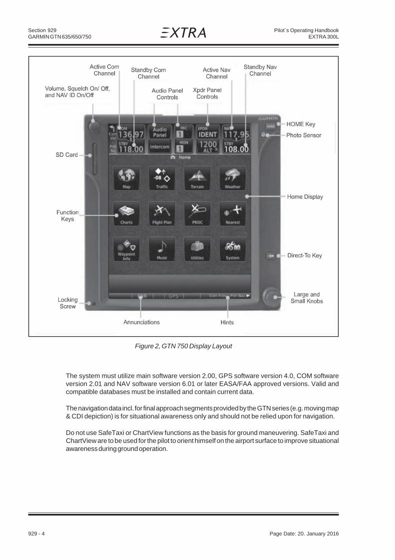
Section 929GARMIN GTN 635/650/750
929 - 4 Page Date: 20. January 2016
Pilot´s Operating HandbookEXTRA 300L
The system must utilize main software version 2.00, GPS software version 4.0, COM softwareversion 2.01 and NAV software version 6.01 or later EASA/FAA approved versions. Valid andcompatible databases must be installed and contain current data.
The navigation data incl. for final approach segments provided by the GTN series (e.g. moving map& CDI depiction) is for situational awareness only and should not be relied upon for navigation.
Do not use SafeTaxi or ChartView functions as the basis for ground maneuvering. SafeTaxi andChartView are to be used for the pilot to orient himself on the airport surface to improve situationalawareness during ground operation.
Figure 2, GTN 750 Display Layout

Section 929GARMIN GTN 635/650/750
Page Date: 20. January 2016 929 - 5
Pilot´s Operating HandbookEXTRA 300L
929.2.1 PLACARDS
(In close proximity to the GTN unit in clear view of the pilot)
(Next to the GTN unit GPS circuit breaker)
(Next to the GMA 35 Remote Audio Panel circuit breaker, if installed)
929.2.2 SD CARD
Proper function of any of the units is predicated on the SD card being present.
929.2.3 TERRAIN
Terrain proximity and obstacle information appears on the map and terrain display pages as redand yellow tiles or towers, and is depicted for advisory use only. Aircraft maneuvers and navigationmust not be predicated upon the use of the terrain display. Terrain proximity and obstacleinformation is advisory only.
The terrain display is intended to serve as a situational awareness tool only. By itself, it may notprovide either the accuracy or the fidelity on which to base decisions and plan maneuvers to avoidterrain or obstacles.
929.2.4 TRAFFIC (TIS ONLY)
Traffic may be displayed on the GTN when connected to an approved optional TIS traffic device. Thissystem is capable of providing traffic monitoring and alerting to the pilot. Traffic shown on the displaymay or may not have traffic alerting available. The display of traffic is an aid to visual acquisition andmay not be utilized solely for aircraft maneuvering.
929.2.5 FLIGHT PLANNING/CALCULATION FUNCTIONS
When using the calculator/planner pages data must be entered into all data fields and verified bythe pilot prior to use of the data. The pilot must verify the desired altitude and appropriate barometricpressure setting to ensure valid calculations. Aircraft performance or fuel loading must not bepredicated upon the use of data derived from these functions.
GARMIN GPSlimited to VFR use only
INTERCOM

Section 929GARMIN GTN 635/650/750
929 - 6 Page Date: 20. January 2016
Pilot´s Operating HandbookEXTRA 300L
929.2.6 GLOVE USE
No device may be used to cover fingers used to operate the GTN unless the Glove QualificationProcedure located in the Pilot's Guide has been successfully completed. The Glove QualificationProcedure is specific to a pilot/glove/GTN unit combination.
929.2.7 DEMO MODE
Demo mode may not be used in flight under any circumstances.
929.3 EMERGENCY/ABNORMAL PROCEDURES
929.3.1 EMERGENCY PROCEDURES
LOSS OF REMOTE AUDIO PANEL FUNCTIONS (IF INSTALLED WITH GTN 750)
Pull INTERCOM circuit breaker
N O T E
This procedure will restore COM operation on the GTN 750. The intercom functions willnot be available.
929.3.2 ABNORMAL PROCEDURES
GPS NAVIGATION INFORMATION NOT AVAILABLE OR INVALID
If GTN 635/650/750 GPS navigation information is not available or invalid the GTN will enter one oftwo modes: Loss of Integrity (LOI) mode or Dead Reckoning (DR) mode. Utilize remainingoperational navigation equipment as appropriate.
A) LOSS OF INTEGRITY MODE
If the amber Loss of Integrity (LOI) Mode message is displayed, revert to an alternate means ofnavigation appropriate to the route and phase of flight or periodically cross-check the GPS guidanceto other, approved means of navigation.

Section 929GARMIN GTN 635/650/750
Page Date: 20. January 2016 929 - 7
Pilot´s Operating HandbookEXTRA 300L
B) DEAD RECKONING MODE
If the amber Dead Reckoning (DR) Mode message is displayed, the course guidance will beremoved from the CDI. The airplane position will be based on the last valid GPS position, thenestimated by Dead Reckoning methods. All information normally derived from GPS will becomeless accurate over time.
SEARCHING A NEARBY AIRPORT
To select a nearby airport as a direct-to waypoint:
1. Press the Direct-To key on the right side of the unit.
2. Touch the NRST APT tab in the Direct-To window. The nearest 25 airports within 200NM willbe listed. The airport at the top of the list is the nearest airport. To review the other nearestairports, touch the Up and Down keys to scroll through the list.
3. Touch the desired airport to select it. The selected airport will be displayed in the Waypointpage.
4. Touch the Activate key or press the small right knob to activate the selection.
5. The Map page will now be displayed with the new Direct-To course.
929.4 NORMAL PROCEDURES
TO ACTIVATE AN EXISTING FLIGHT PLAN:
1. Press the Direct-To key on the right side of the unit.
2. Touch the FPL tab in the Direct-To window.
3. Touch the flight plan waypoint you want to navigate directly to. The Direct-To Waypoint pagewill display information about the selected flight plan waypoint.
4. Touch the Activate key or press the small right knob to activate the selection.
5. The Map page will now be displayed with the new Direct-To course.
929.5 PERFORMANCE
Not affected.

Section 929GARMIN GTN 635/650/750
929 - 8 Page Date: 20. January 2016
Pilot´s Operating HandbookEXTRA 300L
929.6 WEIGHT & CENTER OF GRAVITY
Refer to the equipment list in Section 6 of this Handbook.
929.7 SYSTEM DESCRIPTION
929.7.1 TOUCHSCREEN, KEY AND KNOB FUNCTIONS
Controls are a combination of a dual concentric rotary knob and push-keys on the bezel with thecolor display providing information as well as active touch areas on the display.
TOUCHSCREEN
The GTN 635/650/750 units feature a touch panel that provides a visual display of both controls andfunctions. The required controls are displayed for the selected function. Keys on the display allowyou to access and control their functions by touching the interactive display. A list of menu itemsmay be scrolled by touching the screen and retaining pressure while sliding your finger up or down.Map displays may be panned by touching the screen and retaining pressure while sliding your fingerin the desired direction.
Touchscreen keys are placed at the lower portion of the display. The keys vary depending on thepage selected. Touch the key to perform the function or access the described information.
You can return to the previous page or exit the current function by touching the Back key.
KEYS
Quickly return to the Home page by pressing the HOME key. Press and hold the HOME key to reachthe Map page.
The Direct_To key provides access to the direct-to function, which allows you to enter a waypointand establishes a direct course to the selected destination.
KNOBS
The Volume knob controls audio volume for the selected COM radio or NAV receiver (if installed)and any external audio input devices (if installed). When the COM radio is active, press the Volumeknob momentarily to disable automatic squelch control for the COM radio. When the NAV radiois active, press the Volume knob momentarily to enable/disable the ident tone for the NAV radio.
The large right and small right knobs are used for data entry and to set the frequencies for thecommunications transceiver or the VOR/Localizer receiver (if installed).

Section 929GARMIN GTN 635/650/750
Page Date: 20. January 2016 929 - 9
Pilot´s Operating HandbookEXTRA 300L
Figure 3, GTN 6xx XPDR Operation
929.7.2 SECURE DIGITAL CARD
A Secure Digital (SD) card is used to load and store various types of data and for various databaseupdates. Ensure the GTN unit is powered off before inserting or removing an SD card.
929.7.3 SELECTING COM/NAV FREQUENCIES
Tuning control normally remains in the COM window and will return after 30 seconds of inactivity.
USING KNOBS
Press the small right knob momentarily to make the NAV window active for editing. The standbyfrequency in blue is active for editing. Turn the large right knob to select the desired megahertz(MHz) value. Turn the small right knob to select the desired kilohertz (kHz) value. Press the smallright knob to transfer the standby frequency to the active window.
USING TOUCHSCREEN
Touch the Standby window. A pull down keypad will appear with the current Standby frequencyhighlighted. Touch the numeric keys to add the desired values and touch Enter to accept thedisplayed value and place it into the Standby window. Touching the XFER key will place theselected frequency directly in the Active window. Touch the Active (top) frequency window to flip/flop the Active and Standby frequencies.

Section 929GARMIN GTN 635/650/750
929 - 10 Page Date: 20. January 2016
Pilot´s Operating HandbookEXTRA 300L
929.7.4 REMOTE TRANSPONDER OPERATION
Optionally, a remote transponder (GTX 33) can be controlled via the GTN 635/650/750 unit. Touchthe transponder window to enter the transponder operation page. See figures 3 and 4 for the GTN6xx and the GTN 750 respectively.
IDENT
1. Touch the IDENT key once to reply with an identifying squawk code.
2. The IDENT key text will change to green to indicate active Ident.
Figure 4, GTN 750 XPDR Operation

Section 929GARMIN GTN 635/650/750
Page Date: 20. January 2016 929 - 11
Pilot´s Operating HandbookEXTRA 300L
STANDBY
1. Touch the Mode key to show a list of available modes (directly accessible from thetransponder operation page on the GTN 750). Touch the Standby key to place the transponderinto Standby mode. The transponder will still be powered, but will not transmit information. Theactive transponder indication and Ident annunciation will be grayed to show they are disabled.
GROUND
1. Touch the Ground key to place the transponder into Ground mode. Mode S replies will beallowed in Ground mode.
ON
1. Touch the On key for Mode A operation. The transponder is "On" and will transmit its squawkcode when interrogated.
ALTITUDE REPORTING
1. Touch the Altitude Reporting key for Mode C operation.
2. The transponder will be "On" and will transmit its squawk code and altitude when interrogated.An "ALT" annunciation will appear when the squawk code is transmitted.
VFR
1. Touch the VFR key to set the VFR squawk code (1200 or 7000 depending on location, seebelow).
SELECTING A SQUAWK CODE
The selected squawk code will always be in use. As you change the squawk code, the original codewill be used untill you are finished selecting the new code.
1. Touch the transponder squawk code window at the top of the display.
2. The XPDR page will be displayed. The Squawk Code value will be active for selection for use bythe active transponder.
3. Touch the numeric keypad, or use the rotary knobs, to select the desired Squawk Code.
4. Then, touch Enter or press the small right knob.
5. The selected Squawk Code will be shown in the XPDR window at the top of the display.

Section 929GARMIN GTN 635/650/750
929 - 12 Page Date: 20. January 2016
Pilot´s Operating HandbookEXTRA 300L
IMPORTANT CODES:
1200 The VFR code for any altitude in the US (Refer to ICAO standards elsewhere)
7000 The VFR code commonly used in Europe (Refer to ICAO standards)
7500 Hijack code (Aircraft is subject to unlawful interference)
7600 Loss of communications
7700 Emergency
7777 Military interceptor operations (Never squawk this code)
0000 Military use (Not enterable)
Avoid selecting code 7500 and all codes in the 7600-7777 range. These trigger special indicatorsin automated facilities. Only the code 7500 will be decoded as the hijack code. An aircraft’stransponder code (if available) is utilized to enhance the tracking capabilities of the ATC facility,therefore care should be taken when making routine code changes.
929.7.5 REMOTE AUDIO PANEL OPERATION (GTN 750 ONLY)
The remote audio panel (GMA 35) can be operated from the GTN 750 only. It incorporates anintercom functionality. The Passenger Address, Cabin Speaker, Marker Beacon and Telephonefunctionalities are not used. See Figure 5 for the GTN750 audio panel operation page.
MIC WINDOW MIC SELECTION
1. Touch the Mic window to toggle between Mic 1 and Mic 2.
2. Note that the selected Mic is automatically monitored.
AUDIO PANEL PAGE MIC SELECTION
1. Touch the Audio Panel key at the top of the display.
2. Touch the desired Mic from the MIC Selection list on the right side of the display.
3. The selected Mic will be shown in the MIC window.
MONITOR
1. Monitor is automatically selected for the associated Com Mic Radio.

Section 929GARMIN GTN 635/650/750
Page Date: 20. January 2016 929 - 13
Pilot´s Operating HandbookEXTRA 300L
Figure 5, GTN 750 Audio Panel Operation
2. Touch the Mon key to toggle between the automatically selected monitored channel (selectedMic) and the other available channels.
AUDIO SPLIT MODE
1. While the Audio Control page is displayed, touch the Split Mode key to display Crew Intercomselections.
2. Touch the Split Mode key again to toggle the Crew Intercom selection off.
3. Touch the Crew Intercom key to toggle activation of the Crew Intercom allowing the Pilot andCo-Pilot to talk to each other.
4. Touch the desired Pilot and Co-Pilot Radio selections.

Section 929GARMIN GTN 635/650/750
929 - 14 Page Date: 20. January 2016
Pilot´s Operating HandbookEXTRA 300L
PLAYBACK CONTROLS
1. While the Audio Control page is displayed, touch the Playback Controls key to display thePlayback Controls selections.
2. Touch the Playback Volume arrows to set volume.
3. Touch the Backward, Play or Forward keys to control the playback of the currently selectedrecording.
4. Touch the Previous or Next keys to select a recording.
INTERCOM SETUP
1. Touch the Intercom window at the top of the display to display the intercom Setup page.
2. Touch the arrow between the Pilot and CO-Pilot to activate communication between thoserecipients. The arrow will be green when communication is active. Touch the arrow again todeactivate communication.
3. Touch the Pilot or Co-Pilot keys to set the Volume and Squelch for the selected item.
4. Touch the Volume arrows to set the desired Volume level.
5. Touch the Auto Squelch key to allow the unit to set the Squelch level automatically. Whenenabled, the Auto Squelch key will display a green bar.
6. Touch the Squelch arrows to set the desired Squelch level.
7. Touch the Back key to return to the Intercom Setup page.
8. Touch the Music 1 or Music 2 keys to set their configuration.
9. Select the recipients for Music Distribution by touching any combination of the Pilot and Co-Pilot keys.
10. Touch the Radio and/or Intercom keys to select the function that when active Music will bemuted.
11. Touch the Volume arrows to set the desired Volume level.
929.7.6 POWERING UP THE GTN 635/650/750
The GTN 635/650/750 power and COM volume are controlled using the power/volume knob at thetop left corner of the unit. Turning it clockwise will turn unit power on and increase the COM radiovolume. After turning the unit on, several system startup pages will be displayed: A copyright page,a software & database versions and dates page and a self-test page. The database confirmationpage shows the current database information on the NavData card (with the valid operating dates,cycle number and database type indicated). The database is updated every 28 days, and must becurrent. Information on database subscriptions is available inside your GTN 635/650/750 package.

Section 929GARMIN GTN 635/650/750
Page Date: 20. January 2016 929 - 15
Pilot´s Operating HandbookEXTRA 300L
To acknowledge or advance to the next page, touch Continue.
929.7.7 MAP PAGE
During most flights, the Map page will be used for situational awareness. The Map page displaysAirports, NAVAIDs, airspace, airways, land data (highways, cities, lakes, rivers, borders, etc.) withnames, wind direction and speed, icons for enabled map features, aircraft icon (with the noserepresenting present position), nav range ring, flight plan legs, a graphic course deviation indicator(CDI) with From - To - Next waypoints, topography scale, terrain overlay.
The Map page is reached by touching the MAP key on the Home page or by pressing and holdingthe Home key.
929.7.8 GROUND OPERATION
N O T E
Do not use SafeTaxi or Chartview functions as the basis for ground maneuvering.SafeTaxi and Chartview functions are not qualified to be used as an airport moving mapdisplay (AMMD).
SafeTaxi and Chartview are to be used by the flight crew to orient themselves on the airport surfaceto improve pilot situational awarness during ground operations.
929.7.9 TRAFFIC DISPLAY (OPTIONAL)
Traffic may be displayed on the GTN when connected to an approved TIS traffic device (e.g. GTX330 or GTX 33). The TIS information is only available in the US. The Garmin GTN 6xx or 7xx CockpitReference Guide or Pilot's Guide provides additional information regarding the functionality of thetraffic device.
The display of traffic is an aid to visual acquisition and may not be utilized solely for aircraftmaneuvering.
929.8 SCREEN CLEANING
The Clean Screen mode makes the touchscreen inactive so the display can be manually cleaned.The front bezel, keypad, and display can be cleaned with a microfiber cloth or with a soft cottoncloth dampened with clean water. DO NOT use any chemical cleaning agents. Care should be takento avoid scratching the surface of the display.
While viewing the Utilities page group, touch the Clean Screen key to start the Screen CleaningMode. Touch the HOME key to exit Screen Cleaning Mode.

Section 929GARMIN GTN 635/650/750
929 - 16 Page Date: 20. January 2016
Pilot´s Operating HandbookEXTRA 300L
Left blank intentionally