Embed Size (px)
Citation preview
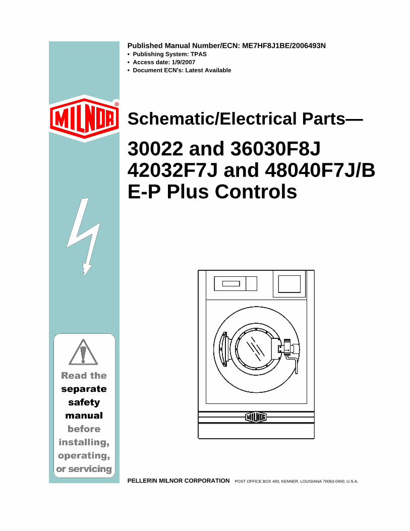
Published Manual Number/ECN: ME7HF8J1BE/2006493N• Publishing System: TPAS• Access date: 1/9/2007• Document ECN's: Latest Available
Schematic/Electrical Parts—
30022 and 36030F8J42032F7J and 48040F7J/BE-P Plus Controls
PELLERIN MILNOR CORPORATION POST OFFICE BOX 400, KENNER, LOUISIANA 70063-0400, U.S.A.

Please Read About the Manual Identifying Information on the Cover The front cover displays pertinent identifying information for this manual. Most important, are the published manual number (part number) /ECN (date code). Generally, when a replacement manual is furnished, it will have the same published manual number, but the latest available ECN. This provides the user with the latest information applicable to his machine. Similarly all documents comprising the manual will be the latest available as of the date the manual was printed, even though older ECN dates for those documents may be listed in the table of contents. When communicating with the Milnor factory regarding this manual, please also provide the other identifying information shown on the cover, including the publishing system, access date, and whether the document ECN’s are the latest available or exact. References to Yellow Troubleshooting Pages This manual may contain references to “yellow pages.” Although the pages containing troubleshooting procedures are no longer printed on yellow paper, troubleshooting instructions, if any, will be contained in the easily located “Troubleshooting” chapter or section. See the table of contents. Trademarks of Pellerin Milnor Corporation The following, some of which may be used in this manual, are trademarks of Pellerin Milnor Corporation:
CBW® E-P Plus® Mildata® MultiTrac™ E-P Express® Gear Guardian® Milnet® Staph Guard® E-P OneTouch® Mentor® Milnor® Visionex™
Comments and Suggestions Help us to improve this manual by sending your comments to:
Pellerin Milnor Corporation Attn: Technical Publications P. O. Box 400 Kenner, LA 70063-0400 Fax: (504) 469-1849
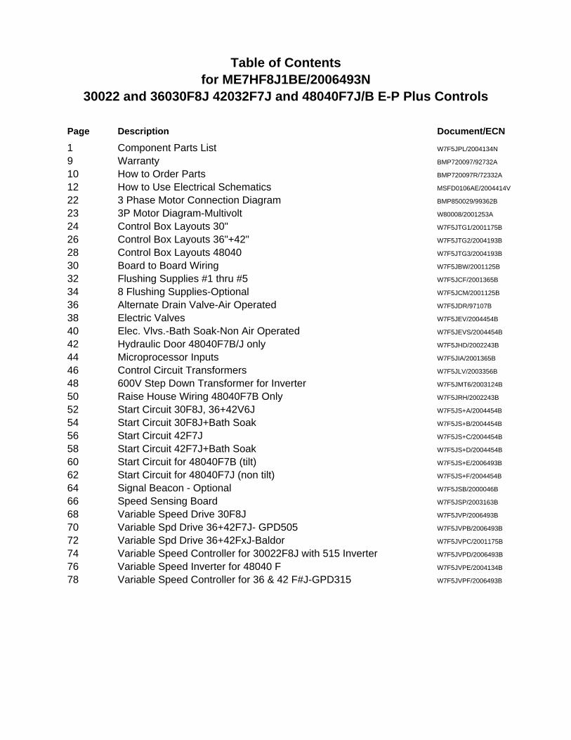
Table of Contentsfor ME7HF8J1BE/2006493N
30022 and 36030F8J 42032F7J and 48040F7J/B E-P Plus Controls
Page Description Document/ECN
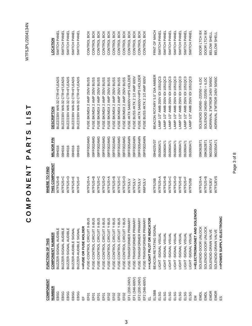
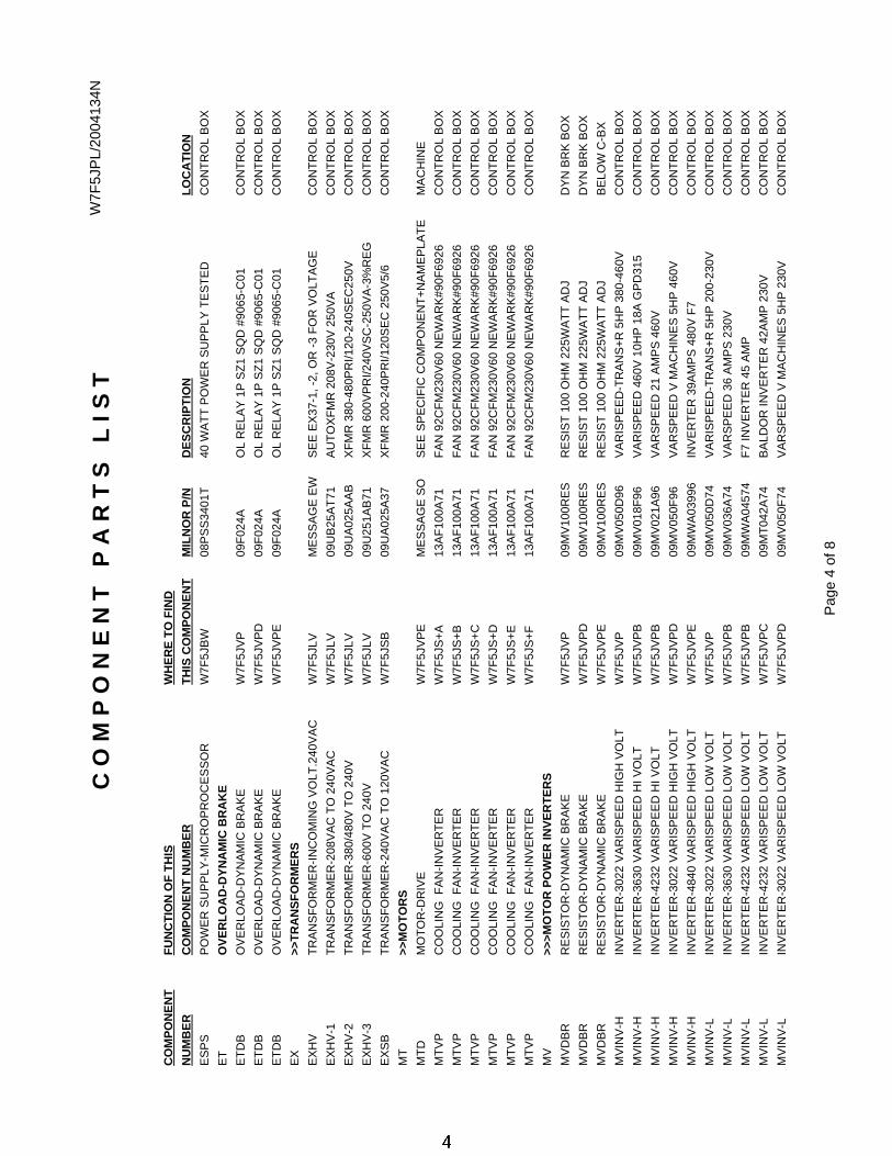
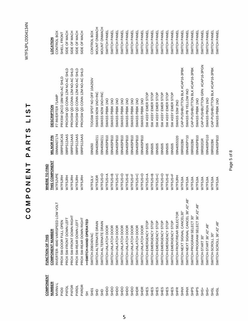
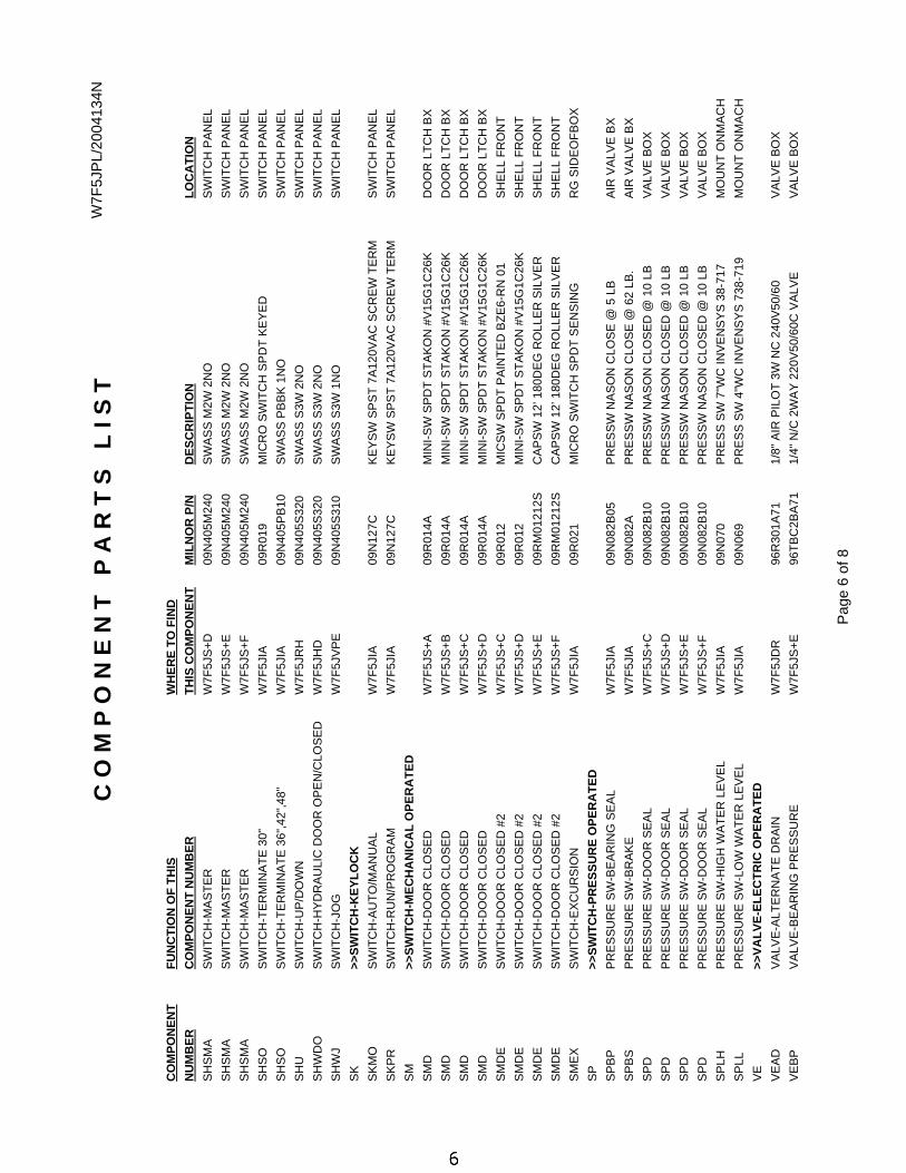
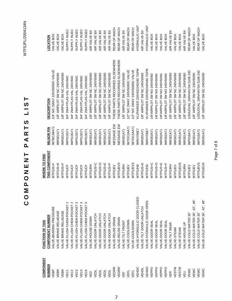
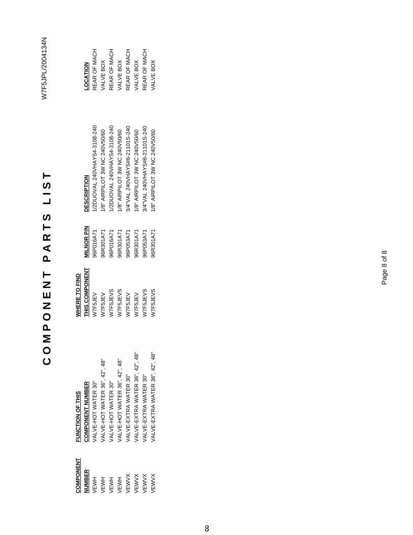
1 Component Parts List W7F5JPL/2004134N
9 Warranty BMP720097/92732A
10 How to Order Parts BMP720097R/72332A
12 How to Use Electrical Schematics MSFD0106AE/2004414V
22 3 Phase Motor Connection Diagram BMP850029/99362B
23 3P Motor Diagram-Multivolt W80008/2001253A
24 Control Box Layouts 30" W7F5JTG1/2001175B
26 Control Box Layouts 36"+42" W7F5JTG2/2004193B
28 Control Box Layouts 48040 W7F5JTG3/2004193B
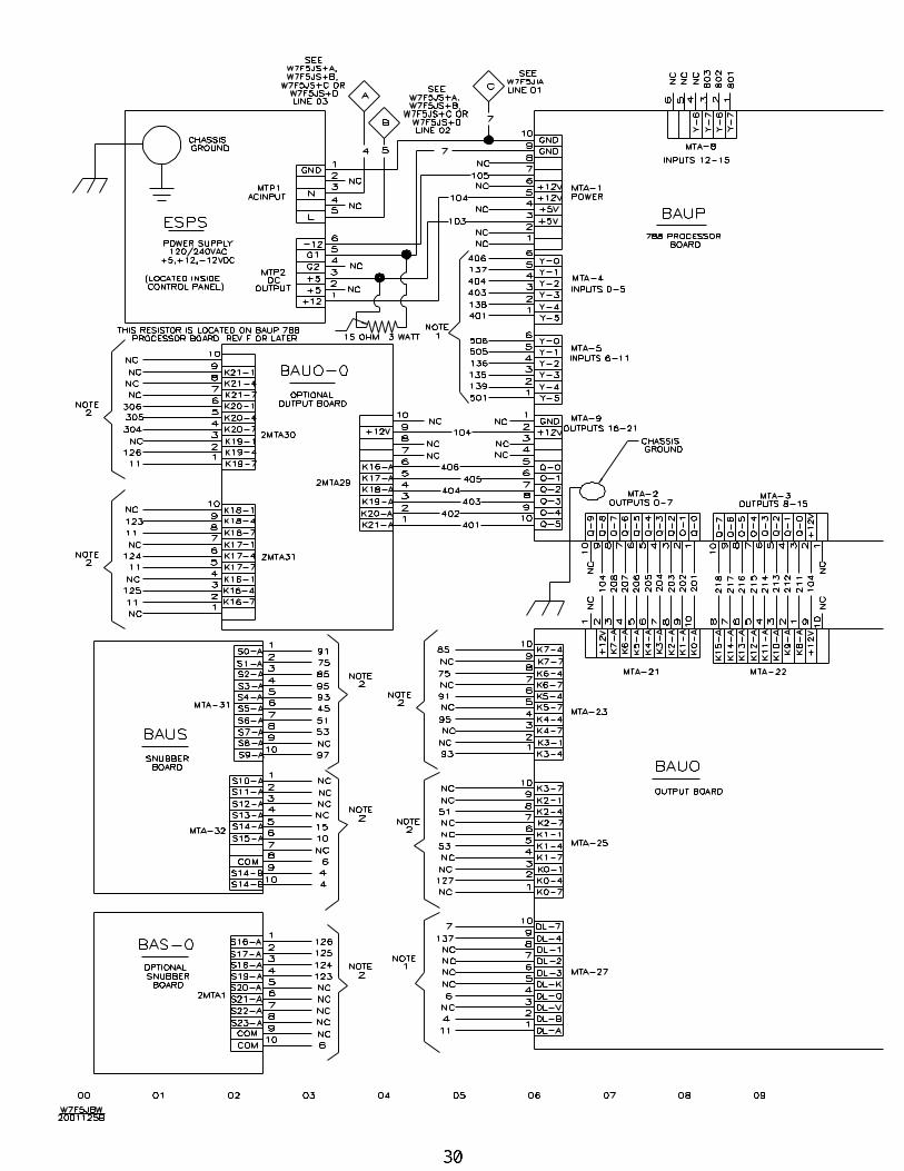
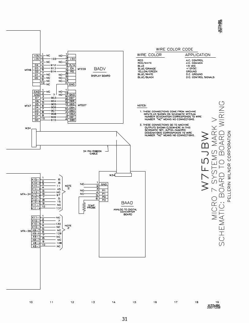
30 Board to Board Wiring W7F5JBW/2001125B
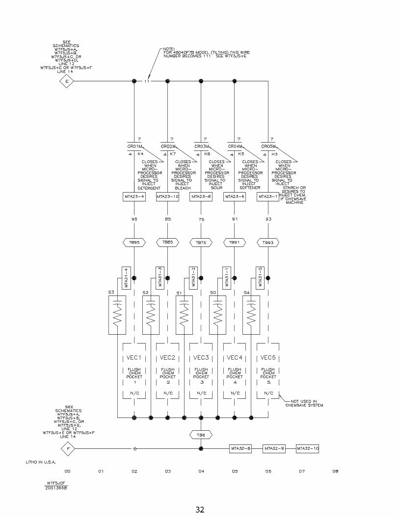
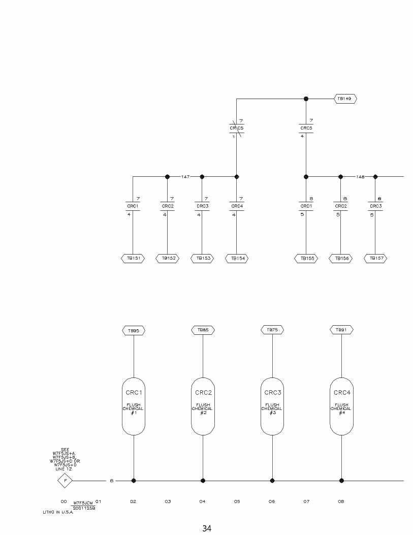
32 Flushing Supplies #1 thru #5 W7F5JCF/2001365B
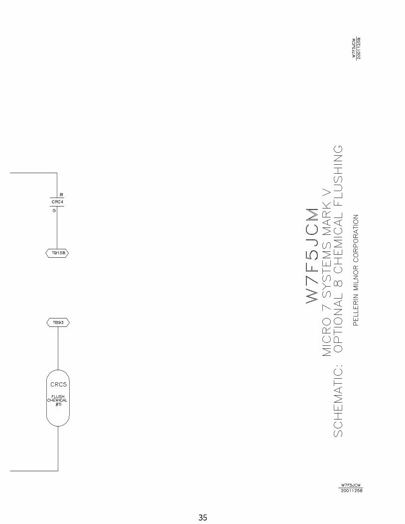
34 8 Flushing Supplies-Optional W7F5JCM/2001125B
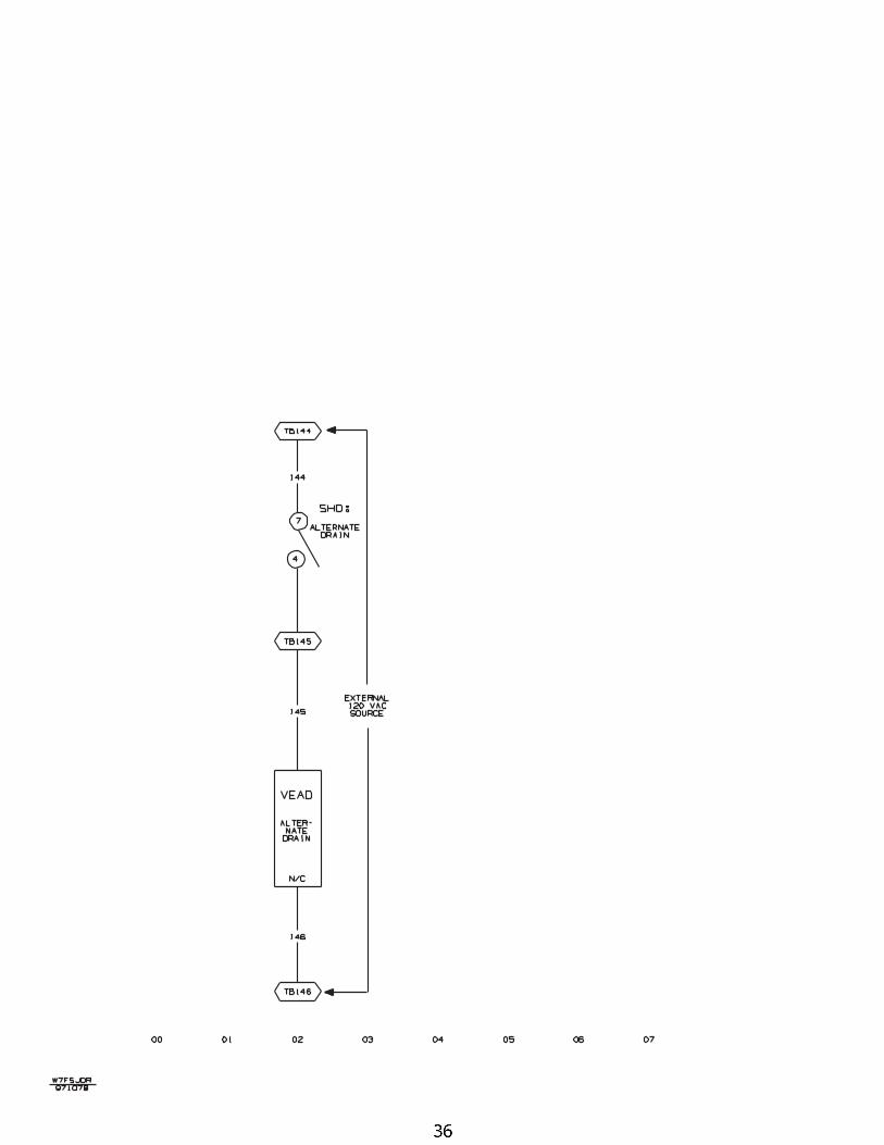
36 Alternate Drain Valve-Air Operated W7F5JDR/97107B
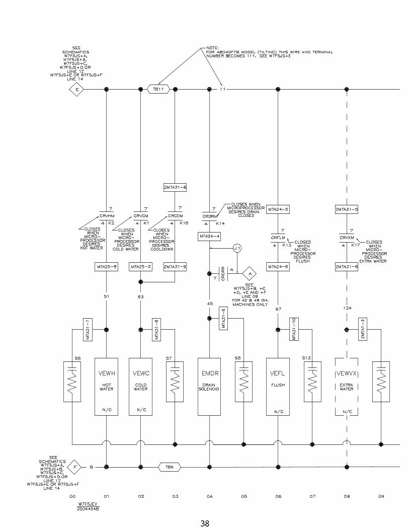
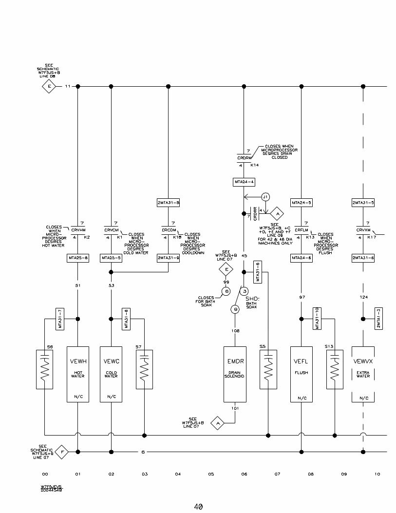
38 Electric Valves W7F5JEV/2004454B
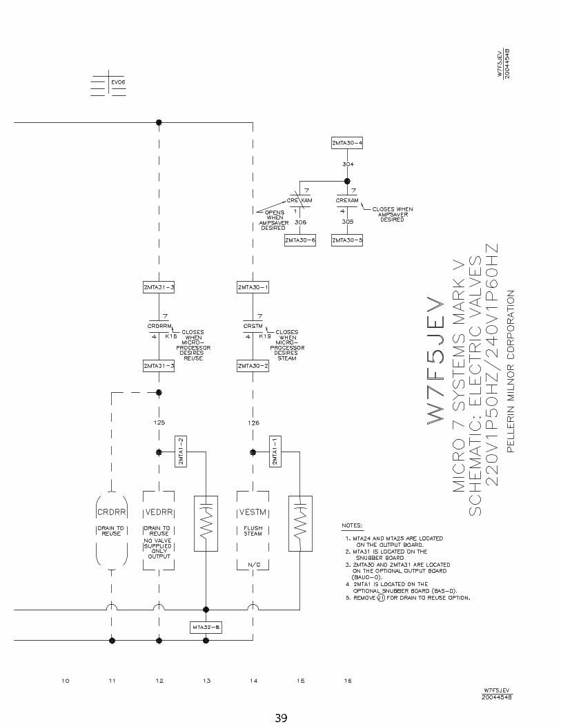
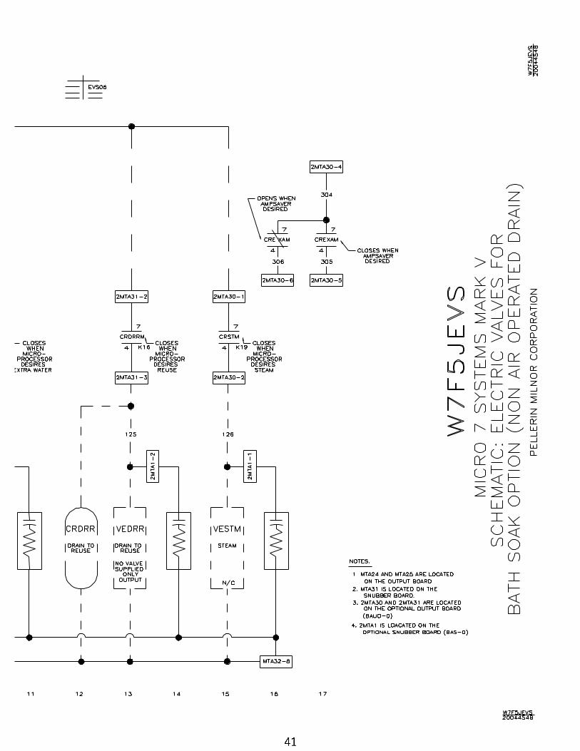
40 Elec. Vlvs.-Bath Soak-Non Air Operated W7F5JEVS/2004454B
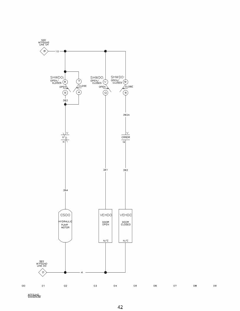
42 Hydraulic Door 48040F7B/J only W7F5JHD/2002243B
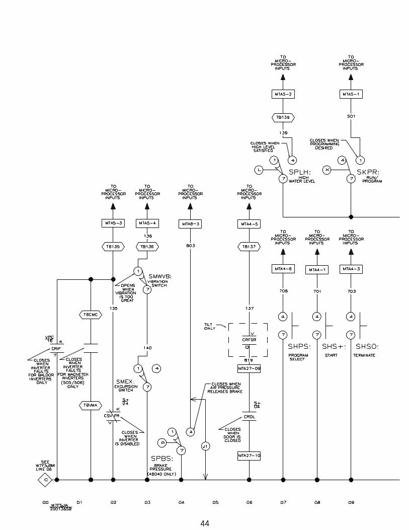
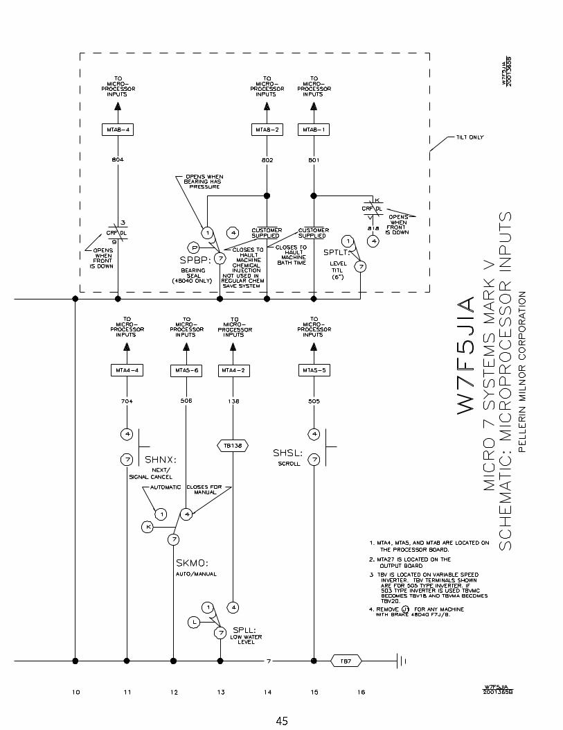
44 Microprocessor Inputs W7F5JIA/2001365B
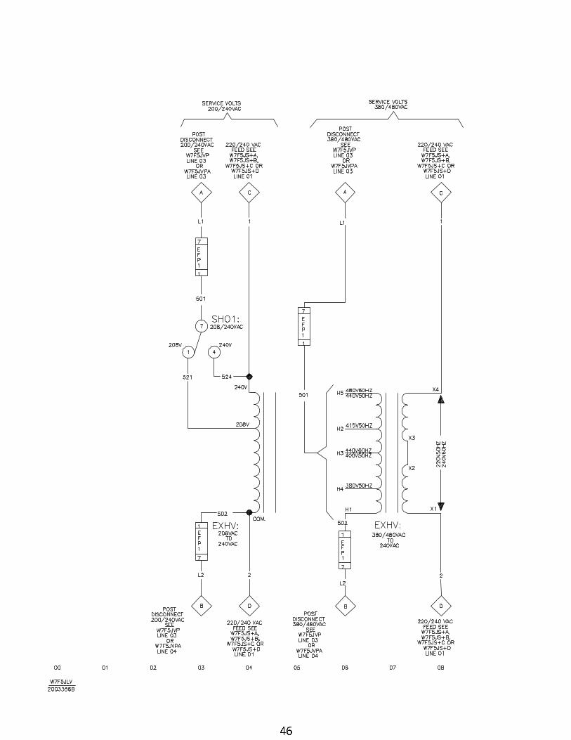
46 Control Circuit Transformers W7F5JLV/2003356B
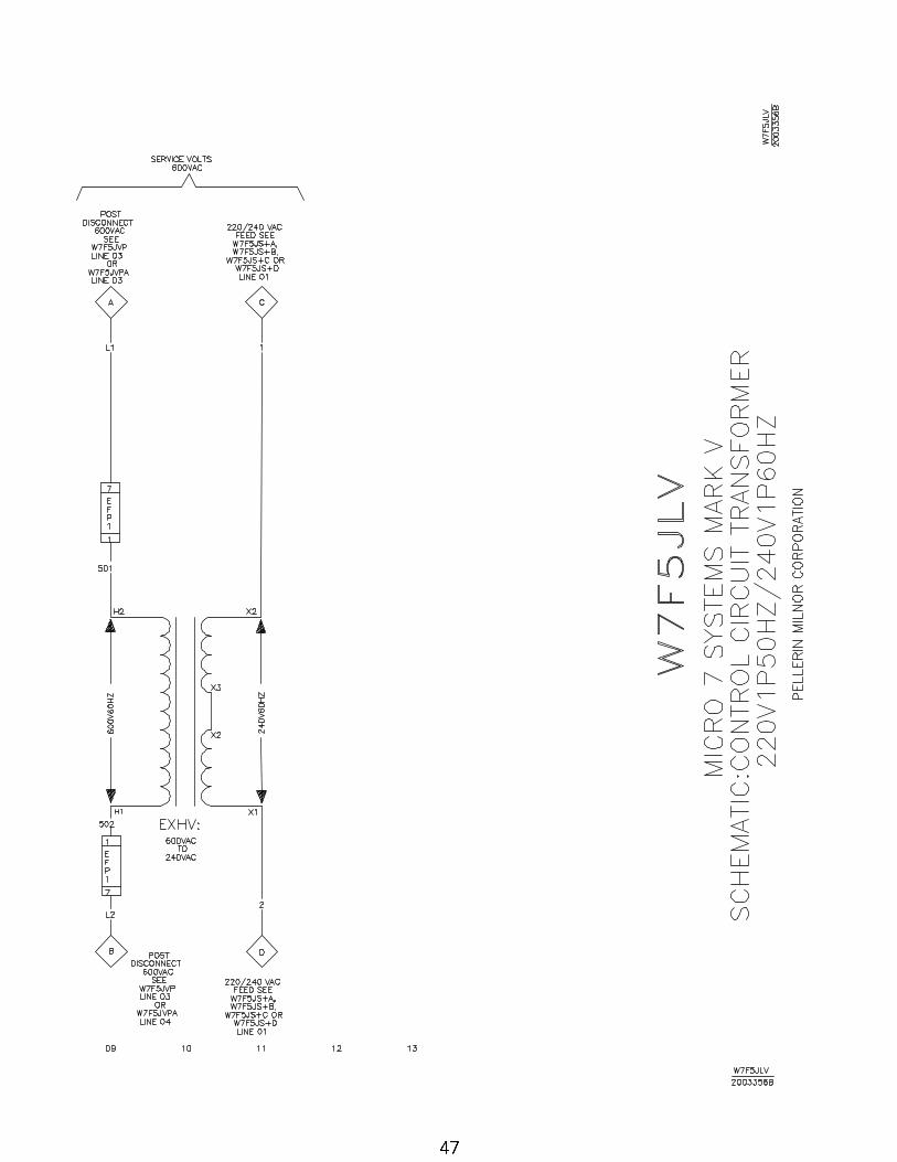
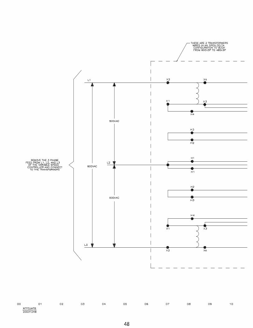
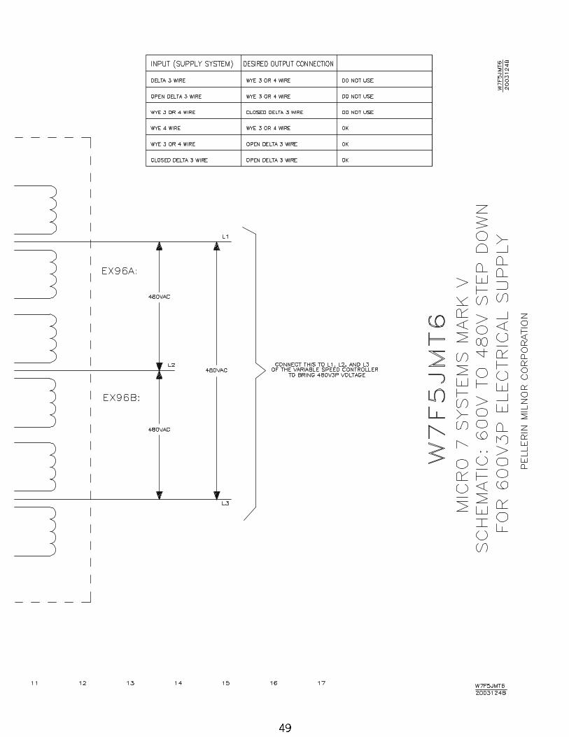
48 600V Step Down Transformer for Inverter W7F5JMT6/2003124B
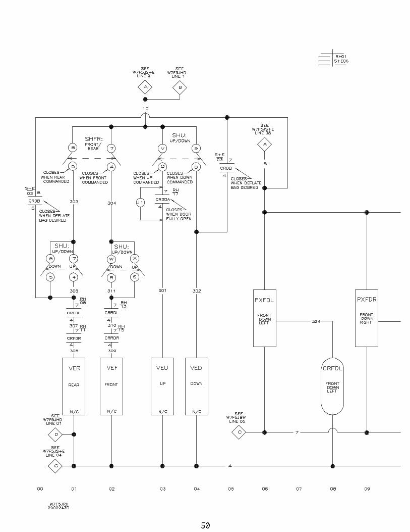
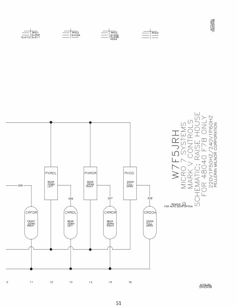
50 Raise House Wiring 48040F7B Only W7F5JRH/2002243B
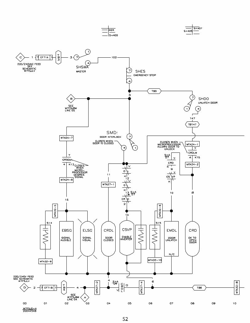
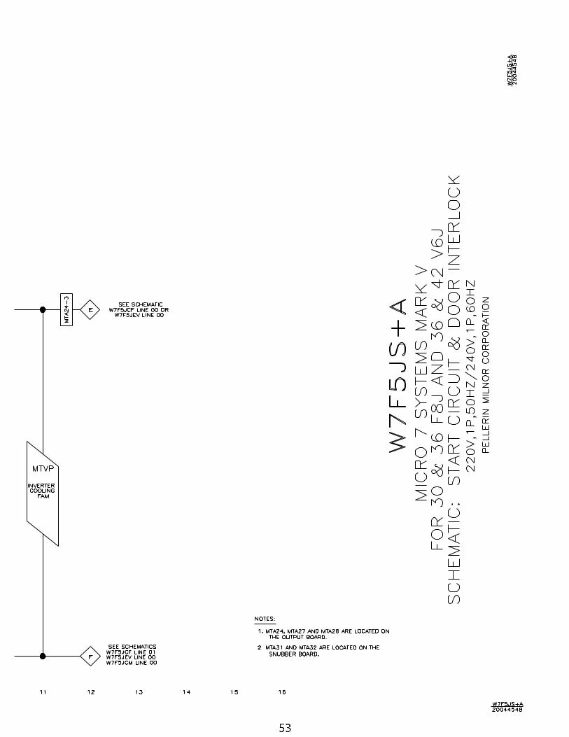
52 Start Circuit 30F8J, 36+42V6J W7F5JS+A/2004454B
54 Start Circuit 30F8J+Bath Soak W7F5JS+B/2004454B
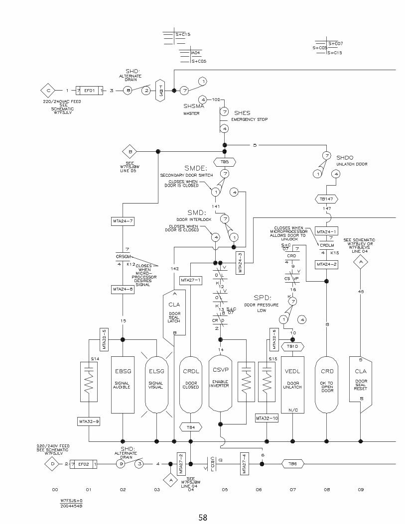
56 Start Circuit 42F7J W7F5JS+C/2004454B
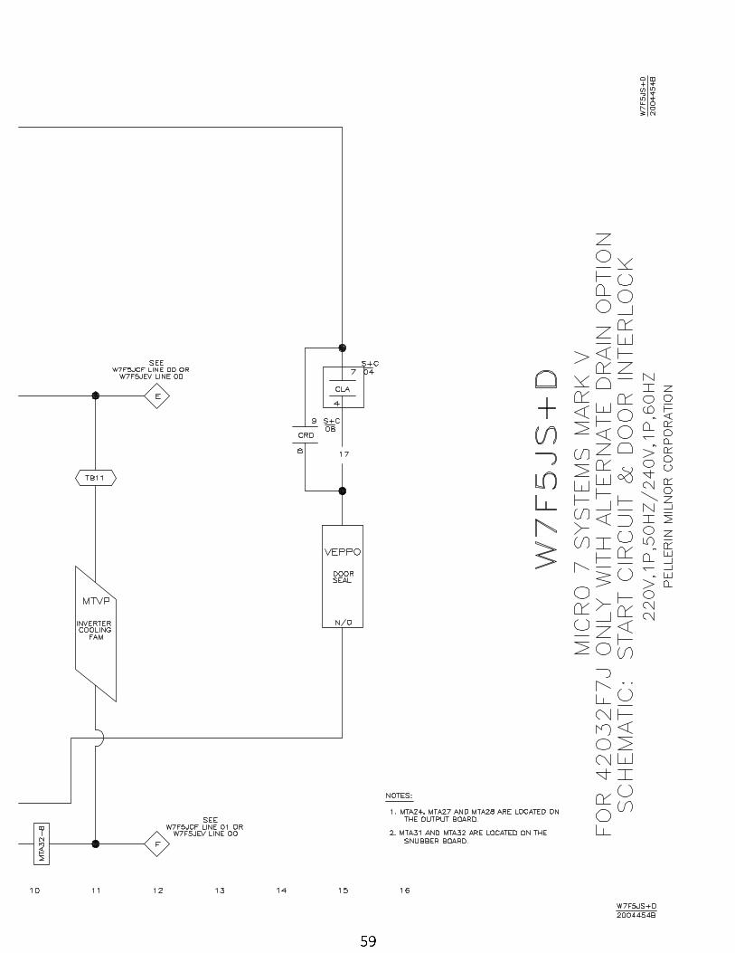
58 Start Circuit 42F7J+Bath Soak W7F5JS+D/2004454B
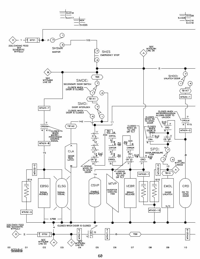
60 Start Circuit for 48040F7B (tilt) W7F5JS+E/2006493B
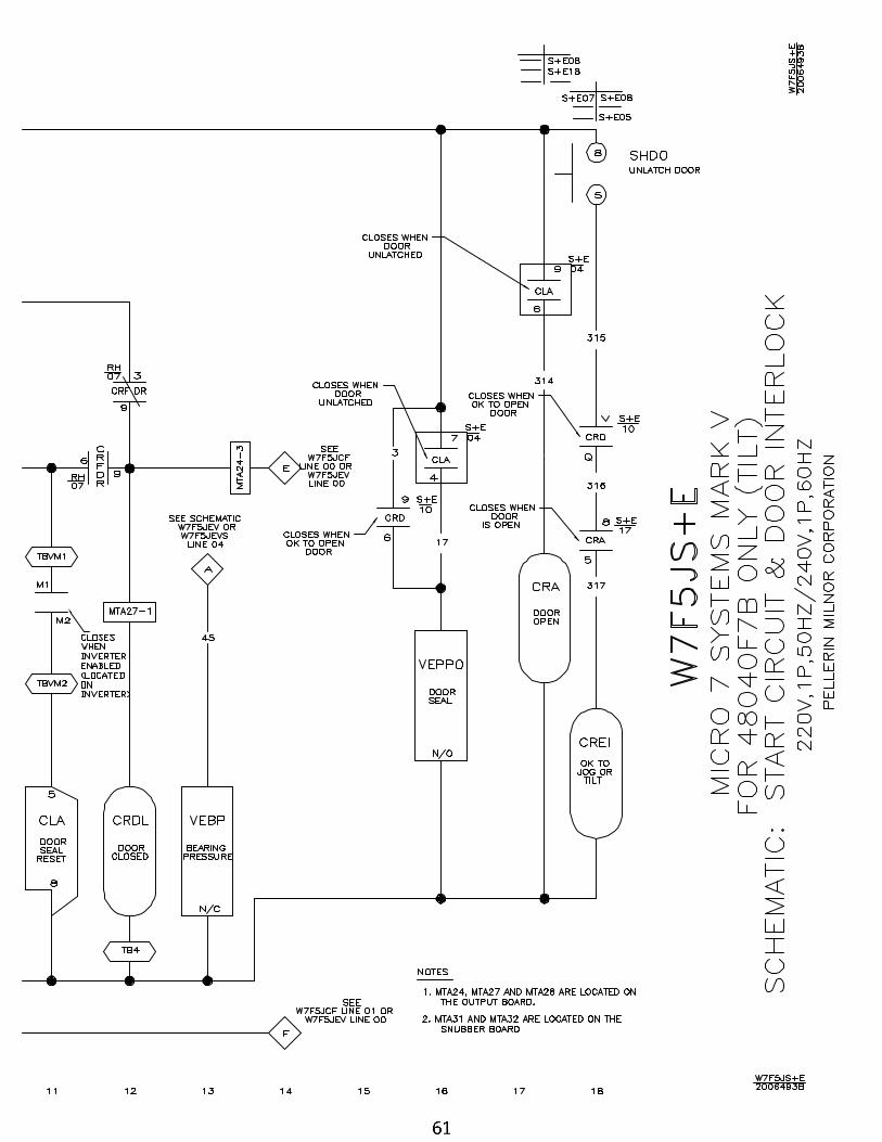
62 Start Circuit for 48040F7J (non tilt) W7F5JS+F/2004454B
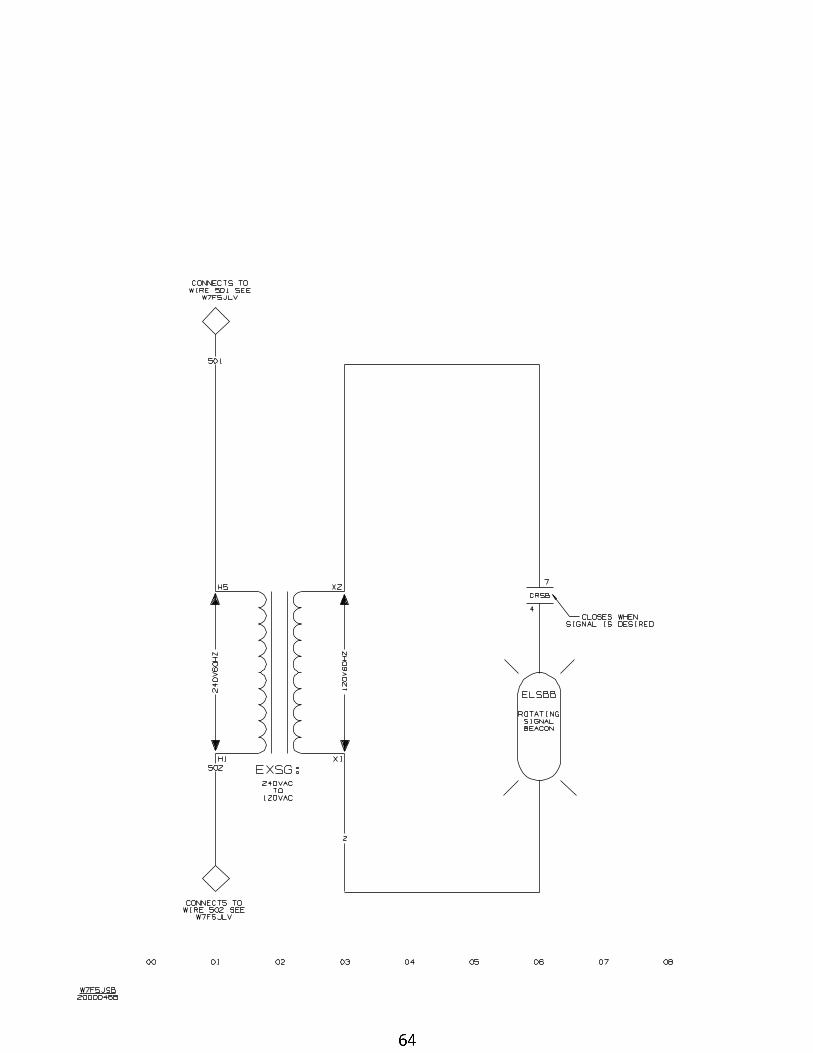
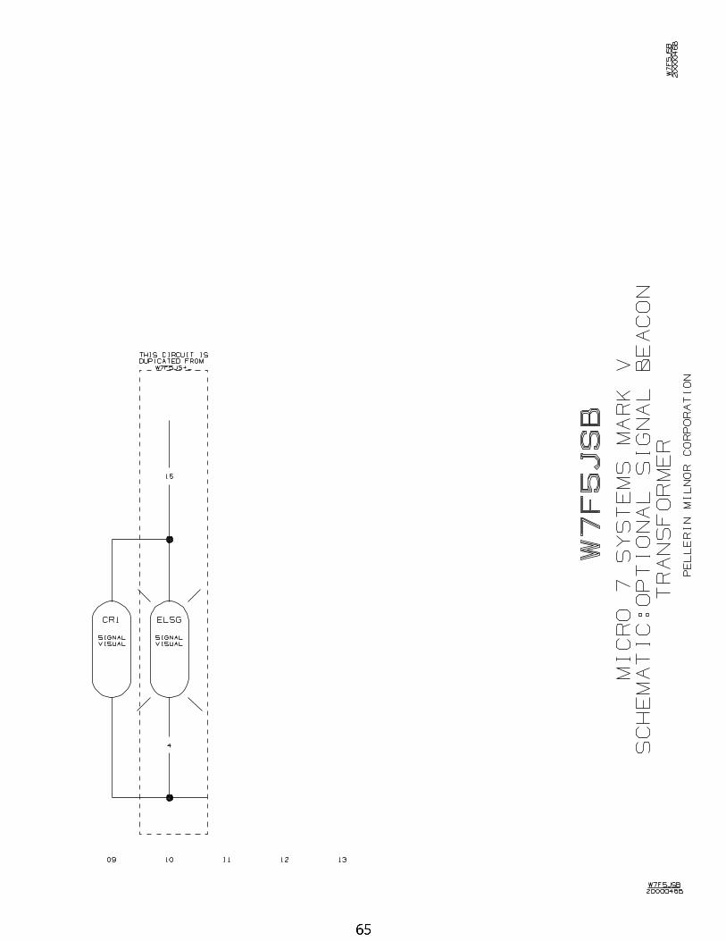
64 Signal Beacon - Optional W7F5JSB/2000046B
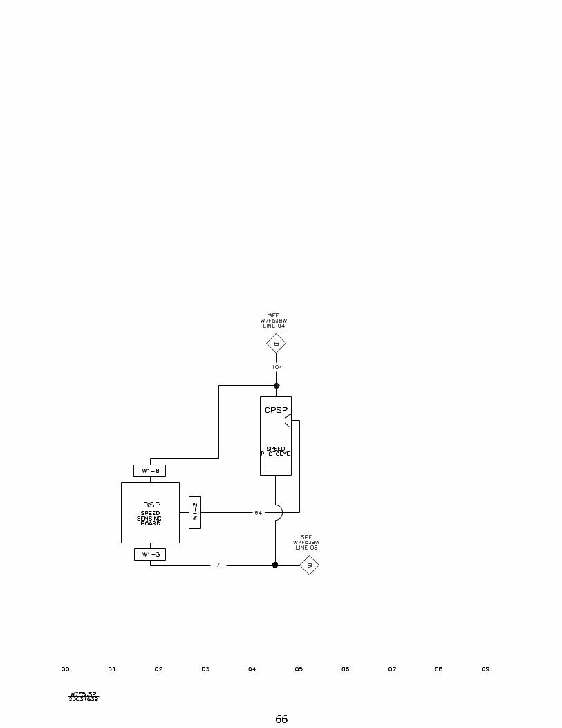
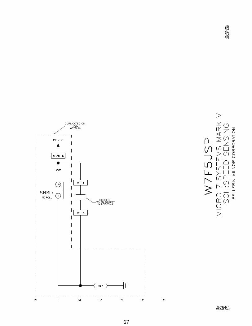
66 Speed Sensing Board W7F5JSP/2003163B
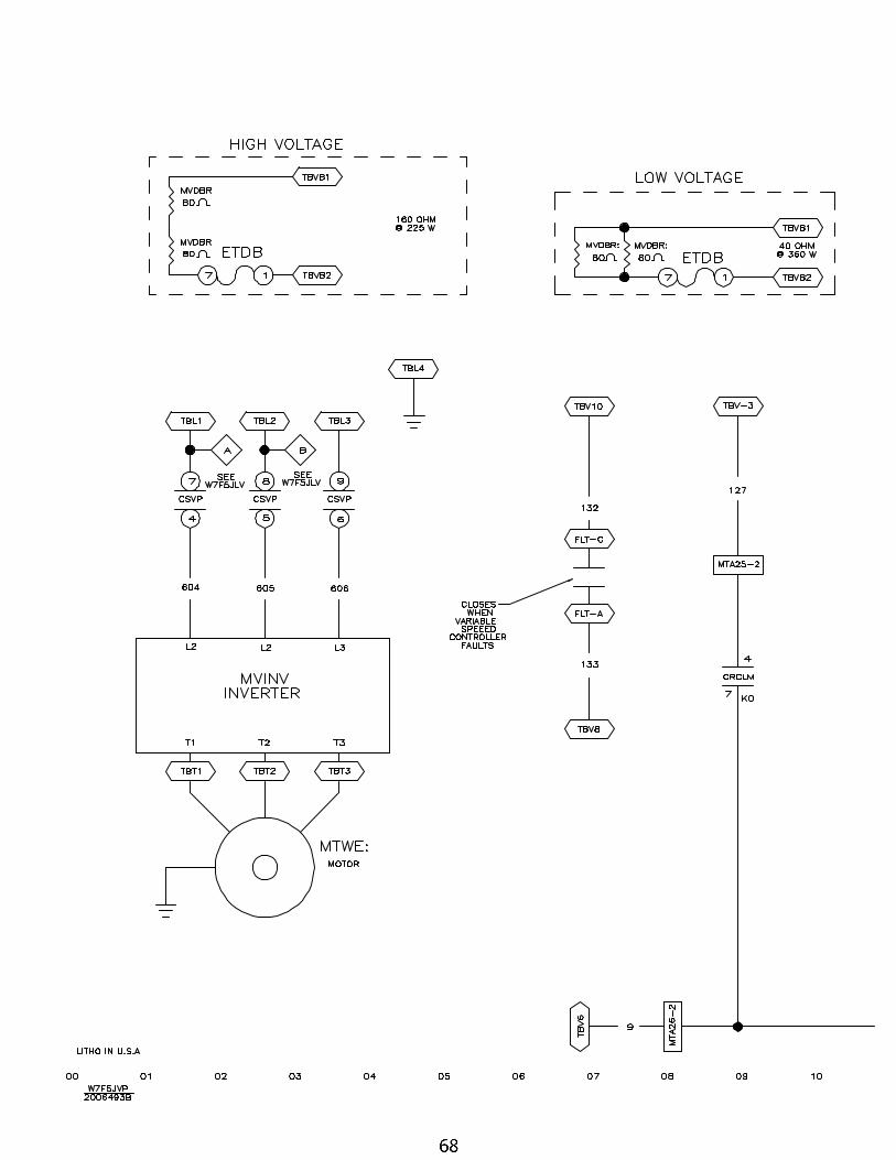
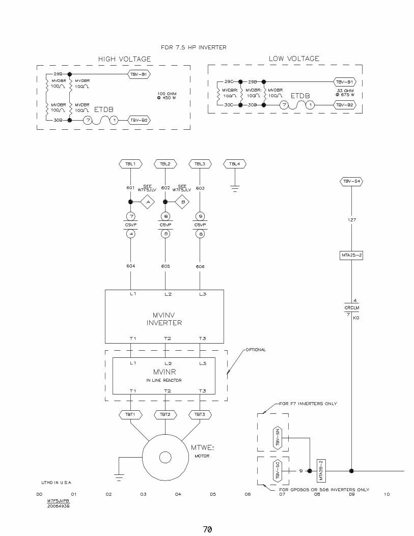
68 Variable Speed Drive 30F8J W7F5JVP/2006493B
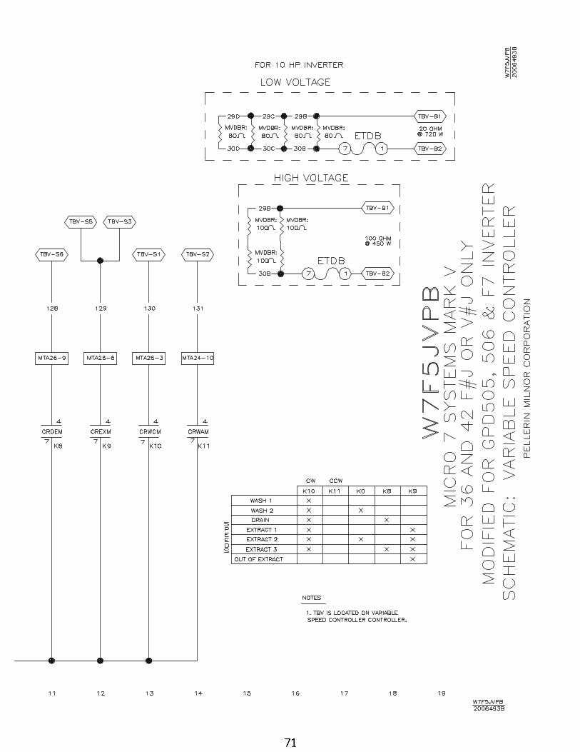
70 Variable Spd Drive 36+42F7J- GPD505 W7F5JVPB/2006493B
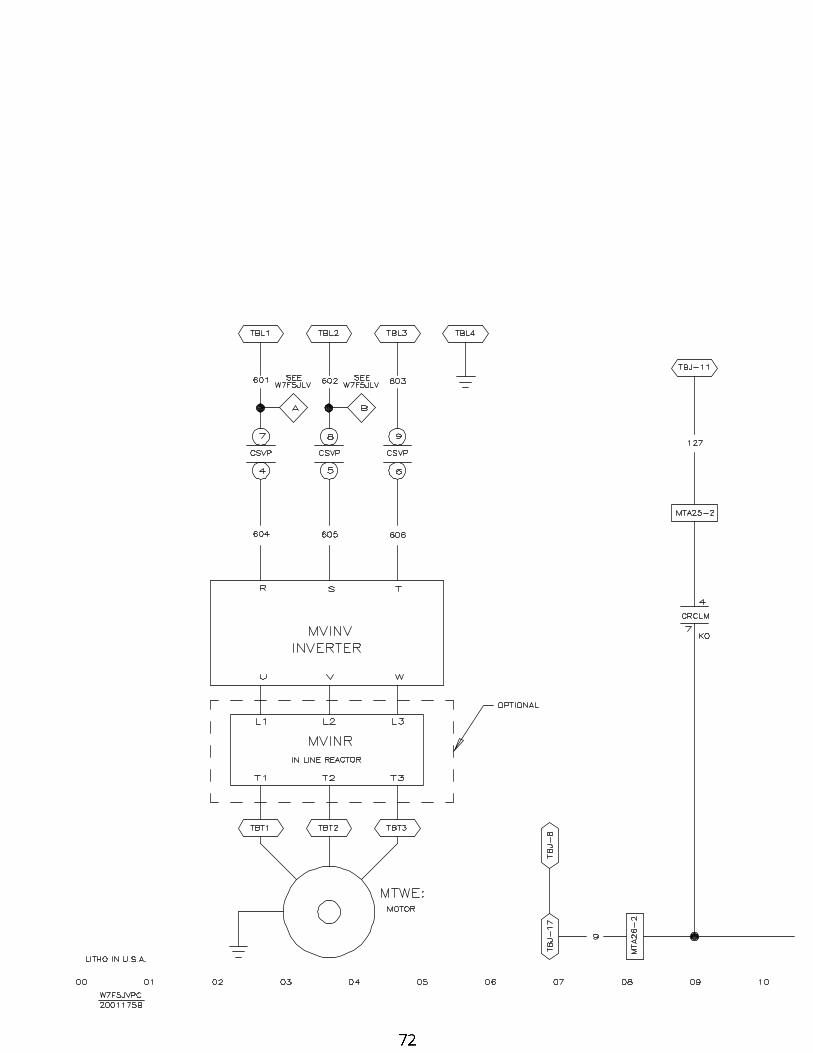
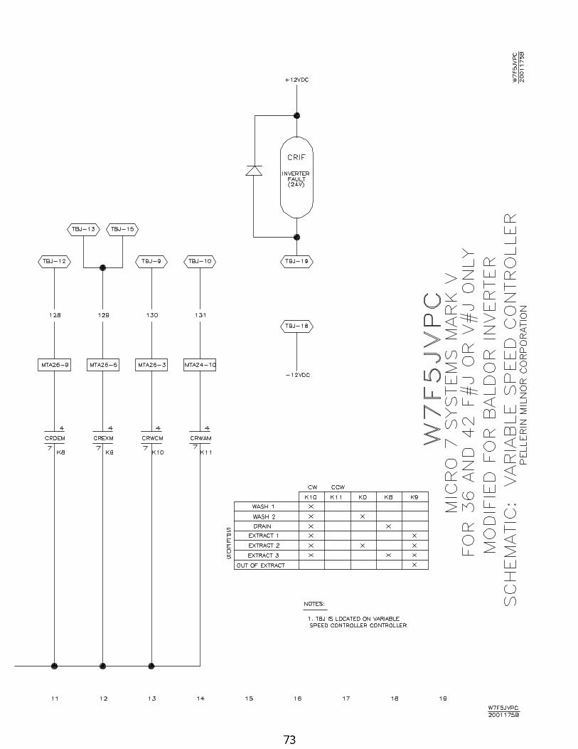
72 Variable Spd Drive 36+42FxJ-Baldor W7F5JVPC/2001175B
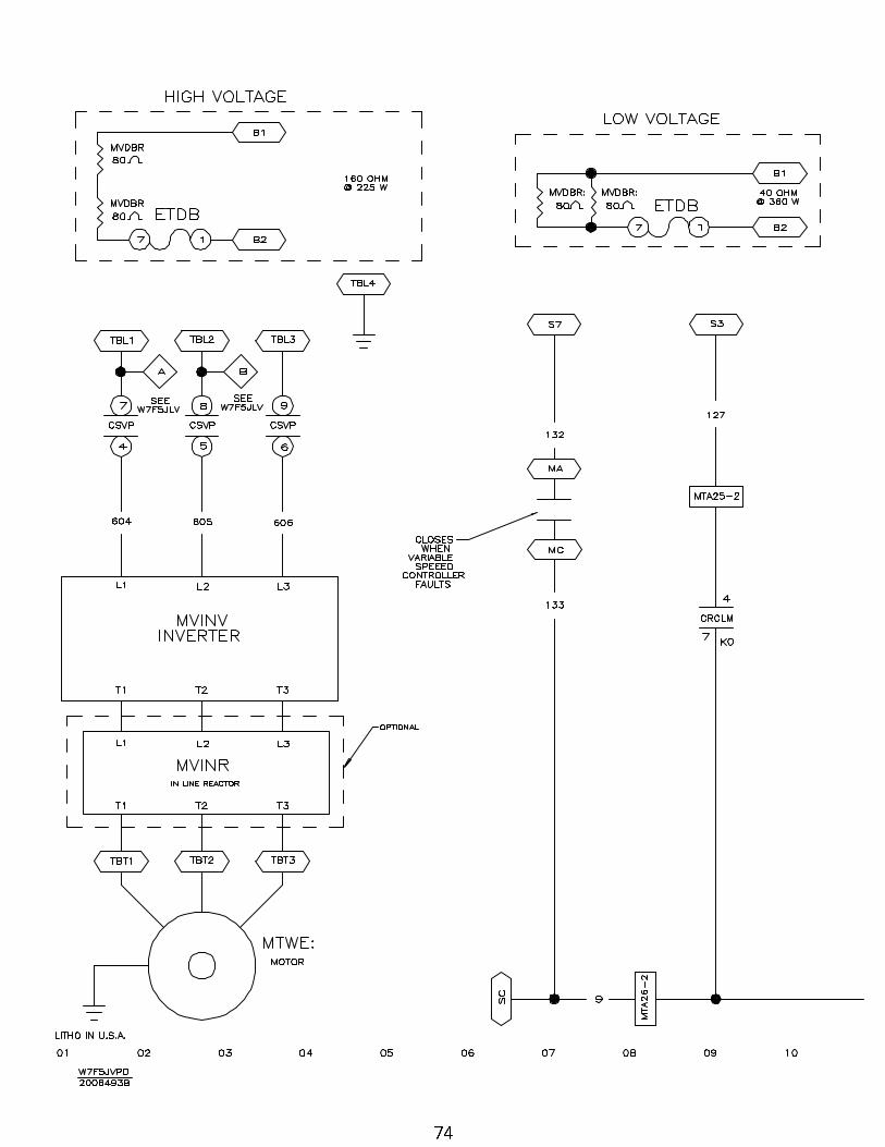
74 Variable Speed Controller for 30022F8J with 515 Inverter W7F5JVPD/2006493B
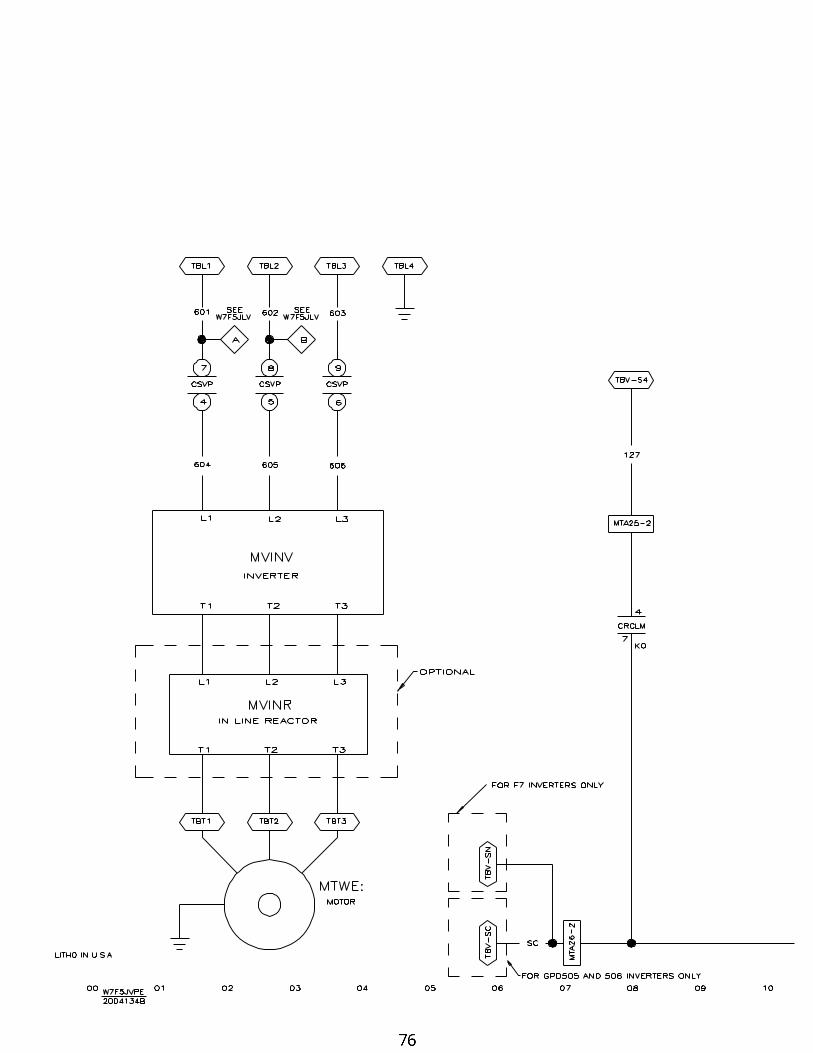
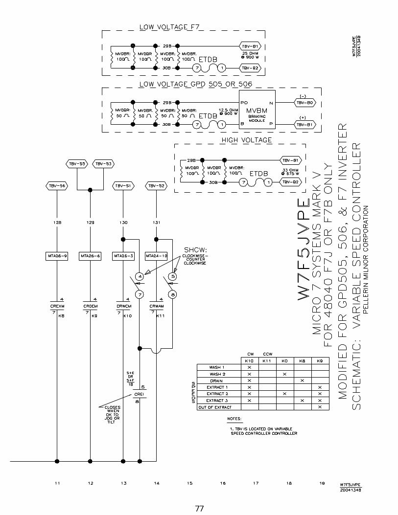
76 Variable Speed Inverter for 48040 F W7F5JVPE/2004134B
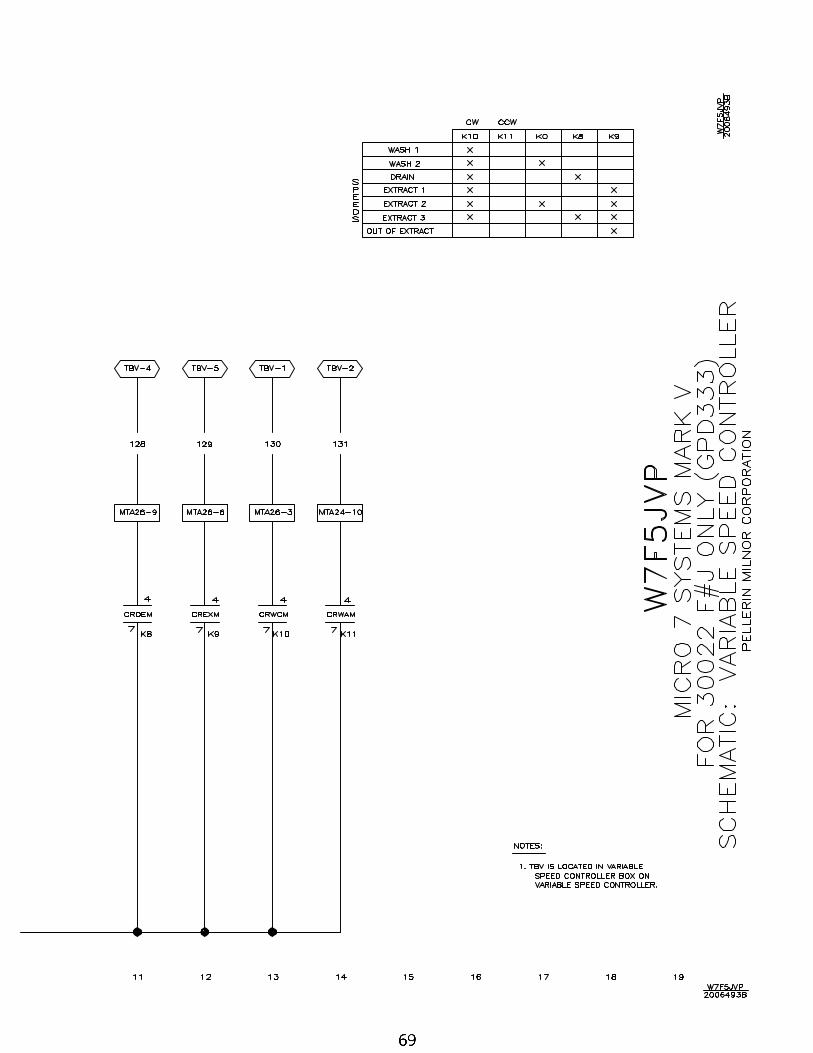
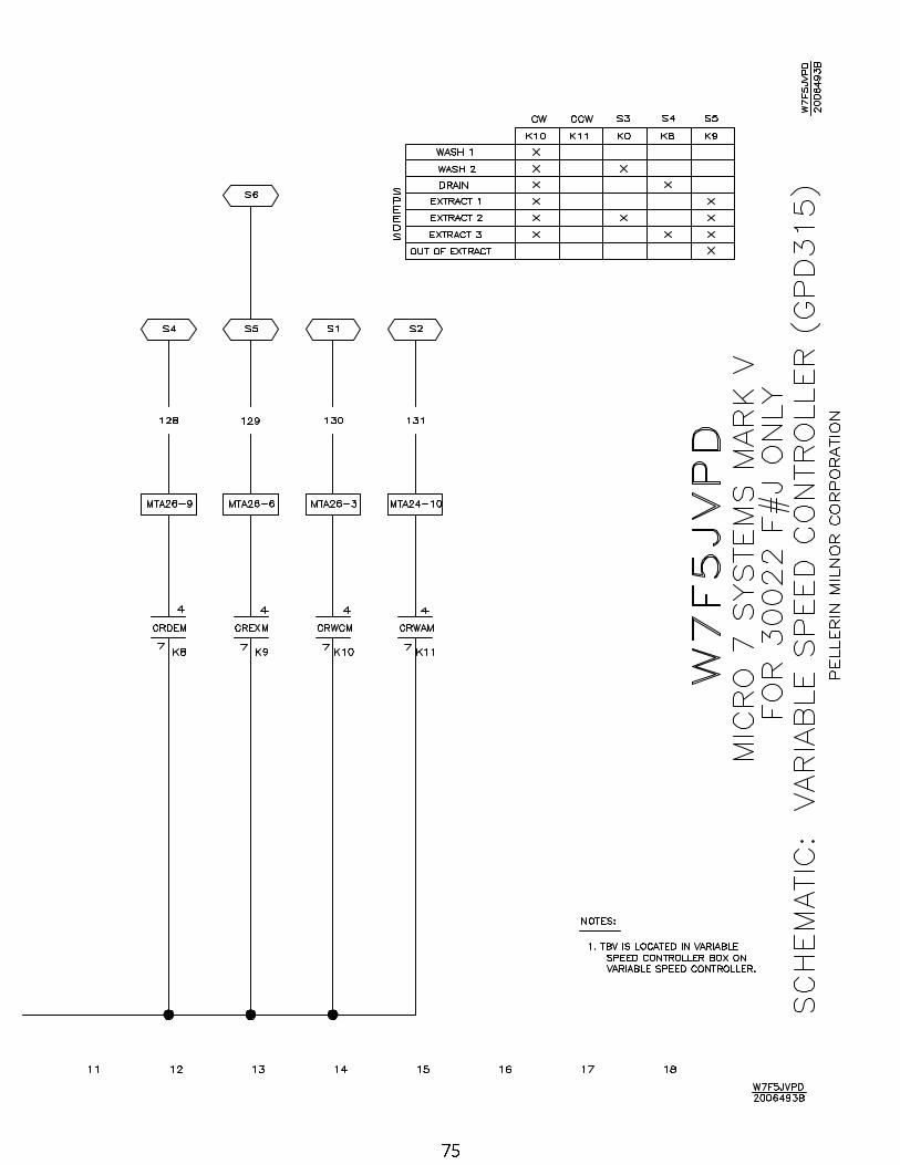
78 Variable Speed Controller for 36 & 42 F#J-GPD315 W7F5JVPF/2006493B

C O
M P
O N
E N
T
P A
R T
S
L I
S T
W
7F5J
PL/
2004
134N
CO
MP
ON
EN
TF
UN
CT
ION
OF
TH
ISW
HE
RE
TO
FIN
D
NU
MB
ER
CO
MP
ON
EN
T N
UM
BE
RT
HIS
CO
MP
ON
EN
TM
ILN
OR
P/N
DE
SC
RIP
TIO
NL
OC
AT
ION
>>C
ON
TR
OL
BO
X L
AY
OU
TS
00
1D
ET
AIL
-300
22 C
ON
TR
OL
BO
XW
7F5J
TG
1B
2TA
G97
080
M5
3002
2F8J
CO
NT
RO
L B
OX
SE
E F
UN
CT
ION
00
2D
ET
AIL
-300
22 P
RO
CE
SS
OR
BO
XW
7F5J
TG
1B
2TA
G96
050
3603
0 F
8J P
RO
CE
SS
OR
BO
XS
EE
FU
NC
TIO
N
00
3D
ET
AIL
-420
32 C
ON
TR
OL
BO
XW
7F5J
TG
2B
2TA
G97
034
4203
2 F
7J C
ON
TR
OL
BO
XS
EE
FU
NC
TIO
N
00
4D
ET
AIL
-LIQ
UID
SU
PP
LIE
S IN
T R
ELA
YW
7F5J
TG
2B
2TA
G96
052
LIQ
UID
SU
PP
LIE
S IN
TR
PR
T R
LYS
EE
FU
NC
TIO
N
00
5D
ET
AIL
-PR
OC
ES
SO
R B
OX
W
7F5J
TG
2B
2TA
G96
050
3603
0 F
8J P
RO
CE
SS
OR
BO
XS
EE
FU
NC
TIO
N
00
6D
ET
AIL
-VA
LVE
AS
SE
MB
LYW
7F5J
TG
2B
2TA
G95
056
TA
G:4
2032
F7
VA
LVE
AS
SE
MB
LYS
EE
FU
NC
TIO
N
00
7D
ET
AIL
-360
30 C
ON
TR
OL
BO
XW
7F5J
TG
2B
2TA
G96
041
3603
0 F
8J C
ON
TR
OL
BO
XS
EE
FU
NC
TIO
N
00
8D
ET
AIL
-480
40 L
OW
VO
LTA
GE
C-B
OX
W7F
5JT
G3
B2T
2000
020
4840
F7J
CN
TR
L B
OX
SE
E F
UN
CT
ION
00
9D
ET
AIL
-480
40 H
IGH
VO
LTA
GE
C-B
OX
W7F
5JT
G3
B2T
2000
021
4804
0F7J
/B/P
HIG
H V
OLT
CN
TL
BX
SE
E F
UN
CT
ION
01
0D
ET
AIL
-480
40 A
IR V
ALV
E B
OX
W7F
5JT
G3
B2T
2000
019
TA
G:4
840
F7N
VA
LVE
SE
TS
EE
FU
NC
TIO
N
BA
>>P
RIN
TE
D C
IRC
UIT
BO
AR
DS
BA
AD
BO
AR
D-A
NA
LOG
TO
DIG
ITA
L C
ON
V.B
D.
W7F
5JB
W08
BN
CM
AD
AT
BD
:CO
IN M
AC
H A
-D C
ON
V-T
ES
TE
DC
ON
TR
OL
BO
X
BA
DV
BO
AR
D-V
AC
UM
N F
LOR
DIS
PLA
YW
7F5J
BW
08B
SE
VF
D2T
VF
D D
ISP
LAY
BU
FF
ER
-SM
-TE
ST
ED
SW
ITC
H P
AN
EL
BA
OB
OA
RD
-OU
TP
UT
16
CH
AN
NE
LW
7F5J
BW
08B
NC
MO
AT
VA
RI S
PD
OU
TP
T F
,V#J
->T
ES
TC
ON
TR
OL
BO
X
BA
OB
OA
RD
OU
TP
UT
W7F
5JB
W08
BN
CM
OT
BD
CO
IN M
AC
H O
UT
PU
T -
>T
ES
TE
DS
WIT
CH
PA
NE
L
BA
SB
OA
RD
-SN
UB
BE
R 1
6 C
HA
NN
EL
W7F
5JB
W08
BN
CM
BT
CO
IN M
AC
HIN
E S
NU
BB
ER
->T
ES
TE
DC
ON
TR
OL
BO
X
BA
S-0
BO
AR
D-S
NU
BB
ER
8 C
HA
NN
EL
W7F
5JB
W08
BN
8SA
T8
CIR
CU
IT S
NU
BB
ER
->T
ES
TE
DC
ON
TR
OL
BO
X
BA
UO
-0B
OA
RD
-OP
TIO
NA
L 6
OU
TP
UT
SW
7F5J
BW
08B
N6O
AT
6 O
UT
PU
T B
OA
RD
->T
ES
TE
DC
ON
TR
OL
BO
X
BA
UP
BO
AR
D-M
ICR
OP
RO
CE
SS
OR
W7F
5JB
W08
BN
788A
TB
D:8
088
PR
OC
22O
UT
-16I
N-T
ES
TP
RO
CE
SS
OR
BX
CL
>>>R
EL
AY
-LA
TC
H
CLA
LAT
CH
-DO
OR
SE
AL
W7F
5JS
+C
09C
LC2C
-C71
RE
LAY
-LA
TC
H D
PD
T 2
40V
2-C
OIL
CO
NT
RO
L B
OX
CLA
LAT
CH
-DO
OR
SE
AL
W7F
5JS
+D
09C
LC2C
-C71
RE
LAY
-LA
TC
H D
PD
T 2
40V
2-C
OIL
CO
NT
RO
L B
OX
CLA
LAT
CH
-DO
OR
SE
AL
W7F
5JS
+E
09C
LC2C
-C71
RE
LAY
-LA
TC
H D
PD
T 2
40V
2-C
OIL
CO
NT
RO
L B
OX
CLA
LAT
CH
-DO
OR
SE
AL
W7F
5JS
+F
09C
LC2C
-C71
RE
LAY
-LA
TC
H D
PD
T 2
40V
2-C
OIL
CO
NT
RO
L B
OX
CR
>>R
EL
AY
-PIL
OT
OR
CO
NT
RO
L
CR
1R
ELA
Y-E
NA
BLE
BA
TH
SO
AK
W7F
5JS
+B
09C
024D
71R
ELA
Y 4
PD
T D
IFG
LD 1
4PN
240
VC
ON
TR
OL
BO
X
CR
AR
ELA
Y O
PE
N D
OO
RW
7F5J
S+
E09
C02
4D71
RE
LAY
4P
DT
DIF
GLD
14P
N 2
40V
CO
NT
RO
L B
OX
CR
C1
RE
LAY
-FLU
SH
CH
EM
ICA
L #1
W7F
5JC
M09
C02
4D71
RE
LAY
4P
DT
DIF
GLD
14P
N 2
40V
CH
EM
OU
T B
OX
CR
C2
RE
LAY
-FLU
SH
CH
EM
ICA
L #2
W7F
5JC
M09
C02
4D71
RE
LAY
4P
DT
DIF
GLD
14P
N 2
40V
CH
EM
OU
T B
OX
CR
C3
RE
LAY
-FLU
SH
CH
EM
ICA
L #3
W7F
5JC
M09
C02
4D71
RE
LAY
4P
DT
DIF
GLD
14P
N 2
40V
CH
EM
OU
T B
OX
CR
C4
RE
LAY
-FLU
SH
CH
EM
ICA
L #4
W7F
5JC
M09
C02
4D71
RE
LAY
4P
DT
DIF
GLD
14P
N 2
40V
CH
EM
OU
T B
OX
CR
C5
RE
LAY
-FLU
SH
CH
EM
ICA
L #5
W7F
5JC
M09
C02
4D71
RE
LAY
4P
DT
DIF
GLD
14P
N 2
40V
CH
EM
OU
T B
OX
Pag
e 1
of 8
C O
M P
O N
E N
T
P A
R T
S
L I
S T
W
7F5J
PL/
2004
134N
CO
MP
ON
EN
TF
UN
CT
ION
OF
TH
ISW
HE
RE
TO
FIN
D
NU
MB
ER
CO
MP
ON
EN
T N
UM
BE
RT
HIS
CO
MP
ON
EN
TM
ILN
OR
P/N
DE
SC
RIP
TIO
NL
OC
AT
ION
CR
CL
RE
LAY
-DO
OR
CLO
SE
DW
7F5J
S+
A
09C
024D
71R
ELA
Y 4
PD
T D
IFG
LD 1
4PN
240
VO
UT
PU
T B
OA
RD
CR
CL
RE
LAY
-DO
OR
CLO
SE
DW
7F5J
S+
B09
C02
4D71
RE
LAY
4P
DT
DIF
GLD
14P
N 2
40V
OU
TP
UT
BO
AR
D
CR
CL
RE
LAY
-DO
OR
CLO
SE
DW
7F5J
S+
C09
C02
4D71
RE
LAY
4P
DT
DIF
GLD
14P
N 2
40V
OU
TP
UT
BO
AR
D
CR
DR
ELA
Y-O
K T
O O
PE
N D
OO
RW
7F5J
S+
A
09C
024D
71R
ELA
Y 4
PD
T D
IFG
LD 1
4PN
240
VC
ON
TR
OL
BO
X
CR
DR
ELA
Y-O
K T
O O
PE
N D
OO
RW
7F5J
S+
B09
C02
4D71
RE
LAY
4P
DT
DIF
GLD
14P
N 2
40V
CO
NT
RO
L B
OX
CR
DR
ELA
Y-O
K T
O O
PE
N D
OO
RW
7F5J
S+
C09
C02
4D71
RE
LAY
4P
DT
DIF
GLD
14P
N 2
40V
CO
NT
RO
L B
OX
CR
DR
ELA
Y-O
K T
O O
PE
N D
OO
RW
7F5J
S+
D09
C02
4D71
RE
LAY
4P
DT
DIF
GLD
14P
N 2
40V
CO
NT
RO
L B
OX
CR
DR
ELA
Y-O
K T
O O
PE
N D
OO
RW
7F5J
S+
E09
C02
4D71
RE
LAY
4P
DT
DIF
GLD
14P
N 2
40V
OU
TP
UT
BO
AR
D
CR
DR
ELA
Y-O
K T
O O
PE
N D
OO
RW
7F5J
S+
F09
C02
4D71
RE
LAY
4P
DT
DIF
GLD
14P
N 2
40V
OU
TP
UT
BO
AR
D
CR
DL
RE
LAY
-DO
OR
CLO
SE
DW
7F5J
S+
D09
C02
4D71
RE
LAY
4P
DT
DIF
GLD
14P
N 2
40V
CO
NT
RO
L B
OX
CR
DL
RE
LAY
-DO
OR
CLO
SE
DW
7F5J
S+
E09
C02
4D71
RE
LAY
4P
DT
DIF
GLD
14P
N 2
40V
CO
NT
RO
L B
OX
CR
DL
RE
LAY
-DO
OR
CLO
SE
DW
7F5J
S+
F09
C02
4D71
RE
LAY
4P
DT
DIF
GLD
14P
N 2
40V
CO
NT
RO
L B
OX
CR
DO
AR
ELA
Y-D
OO
R F
ULL
OP
EN
W7F
5JR
H09
C02
4D71
RE
LAY
4P
DT
DIF
GLD
14P
N 2
40V
CO
NT
RO
L B
OX
CR
EI
RE
LAY
-OK
TO
JO
G O
R T
ILT
W7F
5JS
+E
09C
024D
71R
ELA
Y 4
PD
T D
IFG
LD 1
4PN
240
VC
ON
TR
OL
BO
X
CR
EI
RE
LAY
-OK
TO
JO
G O
R T
ILT
W7F
5JS
+F
09C
024D
71R
ELA
Y 4
PD
T D
IFG
LD 1
4PN
240
VC
ON
TR
OL
BO
X
CR
FD
LR
ELA
Y-F
RO
NT
DO
WN
LE
FT
W7F
5JR
H09
C02
4D71
RE
LAY
4P
DT
DIF
GLD
14P
IN 2
40V
CO
NT
RO
L B
OX
CR
FD
RR
ELA
Y-F
RO
NT
DO
WN
RIG
HT
W7F
5JR
H09
C02
4D71
RE
LAY
4P
DT
DIF
GLD
14P
IN 2
40V
CO
NT
RO
L B
OX
CR
IFR
ELA
Y-I
NV
ER
TE
R F
AU
LTW
7F5J
VP
C09
C02
DD
D24
RE
LAY
3P
DT
SIL
VE
R 1
1PIN
24V
DC
CO
NT
RO
L B
OX
CR
RD
LR
ELA
Y-R
EA
R D
OW
N L
EF
TW
7F5J
RH
09C
024D
71R
ELA
Y 4
PD
T D
IFG
LD 1
4PIN
240
VC
ON
TR
OL
BO
X
CR
RD
RR
ELA
Y-R
EA
R D
OW
N R
IGH
TW
7F5J
RH
09C
024D
71R
ELA
Y 4
PD
T D
IFG
LD 1
4PIN
240
VC
ON
TR
OL
BO
X
CR
SB
RE
LAY
-SIG
NA
L B
EA
CO
NW
7F5J
SB
09C
024D
71R
ELA
Y 4
PD
T D
IFG
LD 1
4PN
240
VC
ON
TR
OL
BO
X
CS
>>C
ON
TA
CT
OR
-MO
TO
R S
TA
RT
ER
CS
DO
CO
NT
AC
TO
R-H
YD
RA
ULI
C P
UM
PW
7F5J
HD
09M
C08
C37
116
A 3
P M
CS
CO
NT
NR
240
V5/
6C
ON
TR
OL
BO
X
CS
VP
CO
NT
AC
TO
R-I
NV
ER
TE
R 3
022
W7F
5JS
+A
09
MC
08C
371
16A
3P
MC
S C
ON
T N
R 2
40V
5/6
CO
NT
RO
L B
OX
CS
VP
CO
NT
AC
TO
R-I
NV
ER
TE
R 3
630
W7F
5JS
+A
09
MC
08G
371
37A
3P
MC
S C
ON
T N
R 2
40V
5/6
CO
NT
RO
L B
OX
CS
VP
CO
NT
AC
TO
R-I
NV
ER
TE
R 3
022
W7F
5JS
+B
09M
C08
C37
116
A 3
P M
CS
CO
NT
NR
240
V5/
6C
ON
TR
OL
BO
X
CS
VP
CO
NT
AC
TO
R-I
NV
ER
TE
R 3
630
W7F
5JS
+B
09M
C08
G37
137
A 3
P M
CS
CO
NT
NR
240
V5/
6C
ON
TR
OL
BO
X
CS
VP
CO
NT
AC
TO
R-I
NV
ER
TE
R 4
232
W7F
5JS
+C
09M
C08
L371
60A
3P
MC
S C
ON
T N
R 2
40V
5/6
CO
NT
RO
L B
OX
CS
VP
CO
NT
AC
TO
R-I
NV
ER
TE
R 4
232
W7F
5JS
+D
09M
C08
L371
60A
3P
MC
S C
ON
T N
R 2
40V
5/6
CO
NT
RO
L B
OX
CS
VP
CO
NT
AC
TO
R-I
NV
ER
TE
R 4
840
W7F
5JS
+E
09M
C08
G37
137
A 3
P M
CS
CO
NT
NR
240
V5/
6C
ON
TR
OL
BO
X
CS
VP
CO
NT
AC
TO
R-I
NV
ER
TE
R 4
840
W7F
5JS
+F
09M
C08
G37
137
A 3
P M
CS
CO
NT
NR
240
V5/
6C
ON
TR
OL
BO
X
EB
>>>B
UZ
ZE
R O
R A
UD
IBL
E S
IGN
AL
EB
SG
BU
ZZ
ER
-SIG
NA
L A
UD
IBLE
W7F
5JS
+A
09
H01
6B
UZ
Z/2
30V
W/6
-32
CT
R+
6"LE
AD
SS
WIT
CH
PA
NE
L
Pag
e 2
of 8
C O
M P
O N
E N
T
P A
R T
S
L I
S T
W
7F5J
PL/
2004
134N
CO
MP
ON
EN
TF
UN
CT
ION
OF
TH
ISW
HE
RE
TO
FIN
D
NU
MB
ER
CO
MP
ON
EN
T N
UM
BE
RT
HIS
CO
MP
ON
EN
TM
ILN
OR
P/N
DE
SC
RIP
TIO
NL
OC
AT
ION
EB
SG
BU
ZZ
ER
-SIG
NA
L A
UD
IBLE
W7F
5JS
+B
09H
016
BU
ZZ
/230
V W
/6-3
2 C
TR
+6"
LEA
DS
SW
ITC
H P
AN
EL
EB
SG
BU
ZZ
ER
-SIG
NA
L A
UD
IBLE
W7F
5JS
+C
09H
016
BU
ZZ
/230
V W
/6-3
2 C
TR
+6"
LEA
DS
SW
ITC
H P
AN
EL
EB
SG
BU
ZZ
ER
-SIG
NA
L A
UD
IBLE
W7F
5JS
+D
09H
016
BU
ZZ
/230
V W
/6-3
2 C
TR
+6"
LEA
DS
SW
ITC
H P
AN
EL
EB
SG
BU
ZZ
ER
-AU
DIB
LE S
IGN
AL
W7F
5JS
+E
09H
016
BU
ZZ
/230
V W
/6-3
2 C
TR
+6"
LEA
DS
SW
ITC
H P
AN
EL
EB
SG
BU
ZZ
ER
-AU
DIB
LE S
IGN
AL
W7F
5JS
+F
09H
016
BU
ZZ
/230
V W
/6-3
2 C
TR
+6"
LEA
DS
SW
ITC
H P
AN
EL
EF
>>F
US
E O
R F
US
E H
OL
DE
R
EF
01F
US
E-C
ON
TR
OL
CIR
CU
IT X
-BU
SW
7F5J
S+
A
09F
F00
2AM
GF
US
E B
K/M
DX
2 A
MP
250
V B
US
SC
ON
TR
OL
BO
X
EF
01F
US
E-C
ON
TR
OL
CIR
CU
IT X
-BU
SW
7F5J
S+
B09
FF
002A
MG
FU
SE
BK
/MD
X 2
AM
P 2
50V
BU
SS
CO
NT
RO
L B
OX
EF
01F
US
E-C
ON
TR
OL
CIR
CU
IT X
-BU
SW
7F5J
S+
C09
FF
002A
MG
FU
SE
BK
/MD
X 2
AM
P 2
50V
BU
SS
CO
NT
RO
L B
OX
EF
01F
US
E-C
ON
TR
OL
CIR
CU
IT X
-BU
SW
7F5J
S+
D09
FF
002A
MG
FU
SE
BK
/MD
X 2
AM
P 2
50V
BU
SS
CO
NT
RO
L B
OX
EF
02F
US
E-C
ON
TR
OL
CIR
CU
IT Y
-BU
SW
7F5J
S+
A
09F
F00
2AM
GF
US
E B
K/M
DX
2 A
MP
250
V B
US
SC
ON
TR
OL
BO
X
EF
02F
US
E-C
ON
TR
OL
CIR
CU
IT Y
-BU
SW
7F5J
S+
B09
FF
002A
MG
FU
SE
BK
/MD
X 2
AM
P 2
50V
BU
SS
CO
NT
RO
L B
OX
EF
02F
US
E-C
ON
TR
OL
CIR
CU
IT Y
-BU
SW
7F5J
S+
C09
FF
002A
MG
FU
SE
BK
/MD
X 2
AM
P 2
50V
BU
SS
CO
NT
RO
L B
OX
EF
02F
US
E-C
ON
TR
OL
CIR
CU
IT Y
-BU
SW
7F5J
S+
D09
FF
002A
MG
FU
SE
BK
/MD
X 2
AM
P 2
50V
BU
SS
CO
NT
RO
L B
OX
EF
1 (2
00-2
40V
)F
US
E-T
RA
NS
FO
RM
ER
PR
IMA
RY
W7F
5JLV
09F
F00
5AW
NF
US
E #
KT
K 5
A60
0V=
HP
S H
OLD
ER
CO
NT
RO
L B
OX
EF
1 (3
46-6
00V
)F
US
E-T
RA
NS
FO
RM
ER
PR
IMA
RY
W7F
5JLV
09F
F00
2AW
NF
US
E B
US
S #
KT
K 2
1/2
AM
P 6
00V
CO
NT
RO
L B
OX
EF
2 (2
00-2
40V
)F
US
E-T
RA
NS
FO
RM
ER
PR
IMA
RY
W7F
5JLV
09F
F00
5AW
NF
US
E #
KT
K 5
A60
0V=
HP
S H
OLD
ER
CO
NT
RO
L B
OX
EF
2 (3
46-6
00V
)F
US
E-T
RA
NS
FO
RM
ER
PR
IMA
RY
W6F
5JLV
09F
F00
2AW
NF
US
E B
US
S #
KT
K 2
1/2
AM
P 6
00V
CO
NT
RO
L B
OX
EL
>>>L
IGH
T P
ILO
T O
R IN
DIC
AT
OR
ELS
BB
BE
AC
ON
-RE
TA
TIN
G S
IGN
AL
W7F
5JS
B09
H02
5V37
BE
AC
ON
RO
TA
RY
5.5
" D
IA A
MB
ER
FR
NT
OF
MA
CH
ELS
GLI
GH
T -
SIG
NA
L V
ISU
AL
W7F
5JS
+A
09
J060
A71
LAM
P 1
/2"
AM
B 2
50V
IDI 1
051Q
C3
SW
ITC
H P
AN
EL
ELS
GLI
GH
T -
SIG
NA
L V
ISU
AL
W7F
5JS
+B
09J0
60A
71LA
MP
1/2
" A
MB
250
V ID
I 105
1QC
3S
WIT
CH
PA
NE
L
ELS
GLI
GH
T -
SIG
NA
L V
ISU
AL
W7F
5JS
+C
09J0
60A
71LA
MP
1/2
" A
MB
250
V ID
I 105
1QC
3S
WIT
CH
PA
NE
L
ELS
GLI
GH
T -
SIG
NA
L V
ISU
AL
W7F
5JS
+D
09J0
60A
71LA
MP
1/2
" A
MB
250
V ID
I 105
1QC
3S
WIT
CH
PA
NE
L
ELS
GLI
GH
T -
SIG
NA
L V
ISU
AL
W7F
5JS
+E
09J0
60A
71LA
MP
1/2
" A
MB
250
V ID
I 105
1QC
3S
WIT
CH
PA
NE
L
ELS
GLI
GH
T -
SIG
NA
L V
ISU
AL
W7F
5JS
+F
09J0
60A
71LA
MP
1/2
" A
MB
250
V ID
I 105
1QC
3S
WIT
CH
PA
NE
L
ELS
GLI
GH
T -
SIG
NA
L V
ISU
AL
W7F
5JS
B09
J060
A71
LAM
P 1
/2"
AM
B 2
50V
IDI 1
051Q
C3
SW
ITC
H P
AN
EL
EM
>>E
LE
CT
RO
MA
GN
ET
AN
D S
OL
EN
OID
EM
DL
SO
LEN
OID
-DO
OR
UN
LOC
KW
7F5J
S+
A
09K
062B
71S
OLE
NO
ID 2
40/6
0--2
20/5
0 =
ILO
CD
OO
R L
TC
H B
X
EM
DL
SO
LEN
OID
-DO
OR
UN
LOC
KW
7F5J
S+
B09
K06
2B71
SO
LEN
OID
240
/60-
-220
/50
= IL
OC
DO
OR
LT
CH
BX
EM
DR
SO
LEN
OID
-DR
AIN
VA
LVE
W7F
5JE
V96
D35
0A71
AD
RIN
VA
L 3"
MT
RD
R 2
40V
50/
60C
BE
LOW
SH
ELL
EM
DR
SO
LEN
OID
-DR
AIN
VA
LVE
W7F
5JE
VS
96D
350A
71A
DR
INV
AL
3"M
TR
DR
240
V 5
0/60
CB
ELO
W S
HE
LL
ES
>>P
OW
ER
SU
PP
LY
-EL
EC
TR
ON
IC
Pag
e 3
of 8
C O
M P
O N
E N
T
P A
R T
S
L I
S T
W
7F5J
PL/
2004
134N
CO
MP
ON
EN
TF
UN
CT
ION
OF
TH
ISW
HE
RE
TO
FIN
D
NU
MB
ER
CO
MP
ON
EN
T N
UM
BE
RT
HIS
CO
MP
ON
EN
TM
ILN
OR
P/N
DE
SC
RIP
TIO
NL
OC
AT
ION
ES
PS
PO
WE
R S
UP
PLY
-MIC
RO
PR
OC
ES
SO
RW
7F5J
BW
08P
SS
3401
T40
WA
TT
PO
WE
R S
UP
PLY
TE
ST
ED
CO
NT
RO
L B
OX
ET
OV
ER
LO
AD
-DY
NA
MIC
BR
AK
E
ET
DB
OV
ER
LOA
D-D
YN
AM
IC B
RA
KE
W7F
5JV
P09
F02
4AO
L R
ELA
Y 1
P S
Z1
SQ
D #
9065
-C01
CO
NT
RO
L B
OX
ET
DB
OV
ER
LOA
D-D
YN
AM
IC B
RA
KE
W7F
5JV
PD
09F
024A
OL
RE
LAY
1P
SZ
1 S
QD
#90
65-C
01C
ON
TR
OL
BO
X
ET
DB
OV
ER
LOA
D-D
YN
AM
IC B
RA
KE
W7F
5JV
PE
09F
024A
OL
RE
LAY
1P
SZ
1 S
QD
#90
65-C
01C
ON
TR
OL
BO
X
EX
>>T
RA
NS
FO
RM
ER
S
EX
HV
TR
AN
SF
OR
ME
R-I
NC
OM
ING
VO
LT.2
40V
AC
W7F
5JLV
ME
SS
AG
E E
WS
EE
EX
37-1
, -2,
OR
-3
FO
R V
OLT
AG
EC
ON
TR
OL
BO
X
EX
HV
-1T
RA
NS
FO
RM
ER
-208
VA
C T
O 2
40V
AC
W7F
5JLV
09U
B25
AT
71A
UT
OX
FM
R 2
08V
-230
V 2
50V
AC
ON
TR
OL
BO
X
EX
HV
-2T
RA
NS
FO
RM
ER
-380
/480
V T
O 2
40V
W7F
5JLV
09U
A02
5AA
BX
FM
R 3
80-4
80P
RI/1
20-2
40S
EC
250V
CO
NT
RO
L B
OX
EX
HV
-3T
RA
NS
FO
RM
ER
-600
V T
O 2
40V
W7F
5JLV
09U
251A
B71
XF
MR
600
VP
RI/2
40V
SC
-250
VA
-3%
RE
GC
ON
TR
OL
BO
X
EX
SB
TR
AN
SF
OR
ME
R-2
40V
AC
TO
120
VA
CW
7F5J
SB
09U
A02
5A37
XF
MR
200
-240
PR
I/120
SE
C 2
50V
5/6
CO
NT
RO
L B
OX
MT
>>M
OT
OR
S
MT
DM
OT
OR
-DR
IVE
W7F
5JV
PE
ME
SS
AG
E S
OS
EE
SP
EC
IFIC
CO
MP
ON
EN
T+
NA
ME
PLA
TE
MA
CH
INE
MT
VP
CO
OLI
NG
FA
N-I
NV
ER
TE
RW
7F5J
S+
A
13A
F10
0A71
FA
N 9
2CF
M23
0V60
NE
WA
RK
#90F
6926
CO
NT
RO
L B
OX
MT
VP
CO
OLI
NG
FA
N-I
NV
ER
TE
RW
7F5J
S+
B13
AF
100A
71F
AN
92C
FM
230V
60 N
EW
AR
K#9
0F69
26C
ON
TR
OL
BO
X
MT
VP
CO
OLI
NG
FA
N-I
NV
ER
TE
RW
7F5J
S+
C13
AF
100A
71F
AN
92C
FM
230V
60 N
EW
AR
K#9
0F69
26C
ON
TR
OL
BO
X
MT
VP
CO
OLI
NG
FA
N-I
NV
ER
TE
RW
7F5J
S+
D13
AF
100A
71F
AN
92C
FM
230V
60 N
EW
AR
K#9
0F69
26C
ON
TR
OL
BO
X
MT
VP
CO
OLI
NG
FA
N-I
NV
ER
TE
RW
7F5J
S+
E13
AF
100A
71F
AN
92C
FM
230V
60 N
EW
AR
K#9
0F69
26C
ON
TR
OL
BO
X
MT
VP
CO
OLI
NG
FA
N-I
NV
ER
TE
RW
7F5J
S+
F13
AF
100A
71F
AN
92C
FM
230V
60 N
EW
AR
K#9
0F69
26C
ON
TR
OL
BO
X
MV
>>>M
OT
OR
PO
WE
R IN
VE
RT
ER
S
MV
DB
RR
ES
IST
OR
-DY
NA
MIC
BR
AK
EW
7F5J
VP
09M
V10
0RE
SR
ES
IST
100
OH
M 2
25W
AT
T A
DJ
DY
N B
RK
BO
X
MV
DB
RR
ES
IST
OR
-DY
NA
MIC
BR
AK
EW
7F5J
VP
D09
MV
100R
ES
RE
SIS
T 1
00 O
HM
225
WA
TT
AD
JD
YN
BR
K B
OX
MV
DB
RR
ES
IST
OR
-DY
NA
MIC
BR
AK
EW
7F5J
VP
E09
MV
100R
ES
RE
SIS
T 1
00 O
HM
225
WA
TT
AD
JB
ELO
W C
-BX
MV
INV
-HIN
VE
RT
ER
-302
2 V
AR
ISP
EE
D H
IGH
VO
LTW
7F5J
VP
09
MV
050D
96V
AR
ISP
EE
D-T
RA
NS
+R
5H
P 3
80-4
60V
CO
NT
RO
L B
OX
MV
INV
-HIN
VE
RT
ER
-363
0 V
AR
ISP
EE
D H
I VO
LTW
7F5J
VP
B09
MV
018F
96V
AR
ISP
EE
D 4
60V
10H
P 1
8A G
PD
315
CO
NT
RO
L B
OX
MV
INV
-HIN
VE
RT
ER
-423
2 V
AR
ISP
EE
D H
I VO
LTW
7F5J
VP
B09
MV
021A
96V
AR
SP
EE
D 2
1 A
MP
S 4
60V
CO
NT
RO
L B
OX
MV
INV
-HIN
VE
RT
ER
-302
2 V
AR
ISP
EE
D H
IGH
VO
LTW
7F5J
VP
D09
MV
050F
96V
AR
SP
EE
D V
MA
CH
INE
S 5
HP
460
VC
ON
TR
OL
BO
X
MV
INV
-HIN
VE
RT
ER
-484
0 V
AR
ISP
EE
D H
IGH
VO
LTW
7F5J
VP
E09
MW
A03
996
INV
ER
TE
R 3
9AM
PS
480
V F
7C
ON
TR
OL
BO
X
MV
INV
-LIN
VE
RT
ER
-302
2 V
AR
ISP
EE
D L
OW
VO
LTW
7F5J
VP
09
MV
050D
74V
AR
ISP
EE
D-T
RA
NS
+R
5H
P 2
00-2
30V
CO
NT
RO
L B
OX
MV
INV
-LIN
VE
RT
ER
-363
0 V
AR
ISP
EE
D L
OW
VO
LTW
7F5J
VP
B09
MV
036A
74V
AR
SP
EE
D 3
6 A
MP
S 2
30V
CO
NT
RO
L B
OX
MV
INV
-LIN
VE
RT
ER
-423
2 V
AR
ISP
EE
D L
OW
VO
LTW
7F5J
VP
B09
MW
A04
574
F7
INV
ER
TE
R 4
5 A
MP
CO
NT
RO
L B
OX
MV
INV
-LIN
VE
RT
ER
-423
2 V
AR
ISP
EE
D L
OW
VO
LTW
7F5J
VP
C09
MT
042A
74B
ALD
OR
INV
ER
TE
R 4
2AM
P 2
30V
CO
NT
RO
L B
OX
MV
INV
-LIN
VE
RT
ER
-302
2 V
AR
ISP
EE
D L
OW
VO
LTW
7F5J
VP
D
09M
V05
0F74
VA
RS
PE
ED
V M
AC
HIN
ES
5H
P 2
30V
CO
NT
RO
L B
OX
Pag
e 4
of 8
C O
M P
O N
E N
T
P A
R T
S
L I
S T
W
7F5J
PL/
2004
134N
CO
MP
ON
EN
TF
UN
CT
ION
OF
TH
ISW
HE
RE
TO
FIN
D
NU
MB
ER
CO
MP
ON
EN
T N
UM
BE
RT
HIS
CO
MP
ON
EN
TM
ILN
OR
P/N
DE
SC
RIP
TIO
NL
OC
AT
ION
MV
INV
-LIN
VE
RT
ER
- 48
40 V
AR
ISP
EE
D L
OW
VO
LTW
7F5J
VP
E09
MW
A07
174
F7
INV
ER
TE
R 7
1AM
PC
ON
TR
OL
BO
X
PX
D0
PR
OX
SW
-DO
OR
FU
LL O
PE
NW
7F5J
RH
09R
PS
18C
AS
PR
XS
W Q
KC
O 1
8M N
O-A
C S
HLD
SH
ELL
FR
ON
T
PX
FD
LP
RO
X S
W-F
RO
NT
DO
WN
LE
FT
W7F
5JR
H09
RP
S12
AA
SP
RO
XS
W Q
D C
ON
N 1
2M N
O-A
C S
HLD
SID
E O
F M
AC
H
PX
FD
RP
RO
X S
W-F
RO
NT
DO
WN
RIG
HT
W7F
5JR
H09
RP
S12
AA
SP
RO
XS
W Q
D C
ON
N 1
2M N
O-A
C S
HLD
SID
E O
F M
AC
H
PX
RD
LP
RO
X S
W-R
EA
R D
OW
N L
EF
TW
7F5J
RH
09R
PS
12A
AS
PR
OX
SW
QD
CO
NN
12M
NO
-AC
SH
LDS
IDE
OF
MA
CH
PX
RD
RP
RO
X S
W-R
EA
R D
OW
N R
IGH
TW
7F5J
RH
09R
PS
12A
AS
PR
OX
SW
QD
CO
NN
12M
NO
-AC
SH
LDS
IDE
OF
MA
CH
SH
>>S
WIT
CH
-HA
ND
OP
ER
AT
ED
SH
01S
WIT
CH
-208
/240
VA
CW
7F5J
LV09
N05
0T
OG
SW
SP
DT
NO
OF
F 1
0A25
0VC
ON
TR
OL
BO
X
SH
DS
WIT
CH
-ALT
ER
NA
TE
DR
AIN
W7F
5JD
R09
N40
5M21
1S
WA
SS
M2W
1N
O+
INC
MO
UN
T O
NM
AC
H
SH
DS
WIT
CH
-ALT
ER
NA
TE
DR
AIN
W7F
5JS
+D
09N
405M
211
SW
AS
S M
2W 1
NO
+IN
CM
OU
NT
ON
MA
CH
SH
DO
SW
ITC
H-U
NLA
TC
H D
OO
RW
7F5J
S+
A
09N
405P
B10
SW
AS
S P
BB
K 1
NO
SW
ITC
H P
AN
EL
SH
DO
SW
ITC
H-U
NLA
TC
H D
OO
RW
7F5J
S+
B09
N40
5PB
10S
WA
SS
PB
BK
1N
OS
WIT
CH
PA
NE
L
SH
DO
SW
ITC
H-U
NLA
TC
H D
OO
RW
7F5J
S+
C09
N40
5PB
10S
WA
SS
PB
BK
1N
OS
WIT
CH
PA
NE
L
SH
DO
SW
ITC
H-U
NLA
TC
H D
OO
RW
7F5J
S+
D09
N40
5PB
10S
WA
SS
PB
BK
1N
OS
WIT
CH
PA
NE
L
SH
DO
SW
ITC
H-U
NLA
TC
H D
OO
RW
7F5J
S+
E09
N40
5PB
10S
WA
SS
PB
BK
1N
OS
WIT
CH
PA
NE
L
SH
DO
SW
ITC
H-U
NLA
TC
H D
OO
RW
7F5J
S+
F09
N40
5PB
10S
WA
SS
PB
BK
1N
OS
WIT
CH
PA
NE
L
SH
DR
SW
ITC
H-U
NLA
TC
H D
OO
RW
7F5J
S+
C09
N40
5PB
10S
WA
SS
PB
BK
1N
OS
WIT
CH
PA
NE
L
SH
DR
SW
ITC
H-U
NLA
TC
H D
OO
RW
7F5J
S+
D09
N40
5PB
10S
WA
SS
PB
BK
1N
OS
WIT
CH
PA
NE
L
SH
ES
SW
ITC
H-E
ME
RG
EN
CY
ST
OP
W7F
5JS
+A
09
N50
5S
W A
SS
Y E
ME
R S
TO
PS
WIT
CH
PA
NE
L
SH
ES
SW
ITC
H-E
ME
RG
EN
CY
ST
OP
W7F
5JS
+B
09N
505
SW
AS
SY
EM
ER
ST
OP
SW
ITC
H P
AN
EL
SH
ES
SW
ITC
H-E
ME
RG
EN
CY
ST
OP
W7F
5JS
+C
09N
505
SW
AS
SY
EM
ER
ST
OP
SW
ITC
H P
AN
EL
SH
ES
SW
ITC
H-E
ME
RG
EN
CY
ST
OP
W7F
5JS
+D
09N
505
SW
AS
SY
EM
ER
ST
OP
SW
ITC
H P
AN
EL
SH
ES
SW
ITC
H-E
ME
RG
EN
CY
ST
OP
W7F
5JS
+E
09N
505
SW
AS
SY
EM
ER
ST
OP
SW
ITC
H P
AN
EL
SH
ES
SW
ITC
H-E
ME
RG
EN
CY
ST
OP
W7F
5JS
+F
09N
505
SW
AS
SY
EM
ER
ST
OP
SW
ITC
H P
AN
EL
SH
FR
SW
ITC
H-F
RO
NT
/RE
AR
SE
LEC
TO
RW
7F5J
RH
09N
405S
320
SW
AS
S S
3W 2
NO
SW
ITC
H P
AN
EL
SH
NX
SW
ITC
H-N
EX
T S
IGN
AL
CA
NC
EL3
0"W
7F5J
IA09
R00
2BK
CA
P-P
US
HB
UT
TO
N B
LK #
CA
P16
-3P
BK
SW
ITC
H P
AN
EL
SH
NX
SW
ITC
H-N
EX
T S
IGN
AL
CA
NC
EL
36",
42",
48"
W7F
5JIA
09N
405P
Y10
SW
AS
S P
B Y
ELL
OW
INO
SW
ITC
H P
AN
EL
SH
PS
SW
ITC
H-P
RO
GR
AM
SE
LEC
T 3
0"W
7F5J
IA09
R00
2BK
CA
P-P
US
HB
UT
TO
N B
LK #
CA
P16
-3P
BK
SW
ITC
H P
AN
EL
SH
PS
SW
ITC
H-P
RO
GR
AM
SE
LEC
T 3
6",4
2",4
8"W
7F5J
IA09
N40
5PB
10S
WA
SS
PB
BK
1N
OS
WIT
CH
PA
NE
L
SH
S+
SW
ITC
H-S
TA
RT
30"
W7F
5JIA
09R
002G
RC
AP
-PU
SH
BU
TT
ON
GR
N #
CA
P16
-3P
GN
SW
ITC
H P
AN
EL
SH
S+
SW
ITC
H-S
TA
RT
36"
,42"
,48"
W7F
5JIA
09N
405P
G10
SW
AS
S P
BG
N 1
NO
SW
ITC
H P
AN
EL
SH
SL
SW
ITC
H-S
CR
OLL
30"
W7F
5JIA
09R
002B
KC
AP
-PU
SH
BU
TT
ON
BLK
#C
AP
16-3
PB
KS
WIT
CH
PA
NE
L
SH
SL
SW
ITC
H-S
CR
OLL
36"
,42"
,48"
W7F
5JIA
09N
405P
B10
SW
AS
S P
BB
K 1
NO
SW
ITC
H P
AN
EL
Pag
e 5
of 8
C O
M P
O N
E N
T
P A
R T
S
L I
S T
W
7F5J
PL/
2004
134N
CO
MP
ON
EN
TF
UN
CT
ION
OF
TH
ISW
HE
RE
TO
FIN
D
NU
MB
ER
CO
MP
ON
EN
T N
UM
BE
RT
HIS
CO
MP
ON
EN
TM
ILN
OR
P/N
DE
SC
RIP
TIO
NL
OC
AT
ION
SH
SM
AS
WIT
CH
-MA
ST
ER
W7F
5JS
+D
09N
405M
240
SW
AS
S M
2W 2
NO
SW
ITC
H P
AN
EL
SH
SM
AS
WIT
CH
-MA
ST
ER
W7F
5JS
+E
09N
405M
240
SW
AS
S M
2W 2
NO
SW
ITC
H P
AN
EL
SH
SM
AS
WIT
CH
-MA
ST
ER
W7F
5JS
+F
09N
405M
240
SW
AS
S M
2W 2
NO
SW
ITC
H P
AN
EL
SH
SO
SW
ITC
H-T
ER
MIN
AT
E 3
0"W
7F5J
IA09
R01
9M
ICR
O S
WIT
CH
SP
DT
KE
YE
DS
WIT
CH
PA
NE
L
SH
SO
SW
ITC
H-T
ER
MIN
AT
E 3
6",4
2",4
8"W
7F5J
IA09
N40
5PB
10S
WA
SS
PB
BK
1N
OS
WIT
CH
PA
NE
L
SH
US
WIT
CH
-UP
/DO
WN
W7F
5JR
H09
N40
5S32
0S
WA
SS
S3W
2N
OS
WIT
CH
PA
NE
L
SH
WD
OS
WIT
CH
-HY
DR
AU
LIC
DO
OR
OP
EN
/CLO
SE
DW
7F5J
HD
09N
405S
320
SW
AS
S S
3W 2
NO
SW
ITC
H P
AN
EL
SH
WJ
SW
ITC
H-J
OG
W7F
5JV
PE
09N
405S
310
SW
AS
S S
3W 1
NO
SW
ITC
H P
AN
EL
SK
>>S
WIT
CH
-KE
YL
OC
K
SK
MO
SW
ITC
H-A
UT
O/M
AN
UA
LW
7F5J
IA09
N12
7CK
EY
SW
SP
ST
7A
120V
AC
SC
RE
W T
ER
M
SW
ITC
H P
AN
EL
SK
PR
SW
ITC
H-R
UN
/PR
OG
RA
M
W7F
5JIA
09N
127C
KE
YS
W S
PS
T 7
A12
0VA
C S
CR
EW
TE
RM
S
WIT
CH
PA
NE
L
SM
>>S
WIT
CH
-ME
CH
AN
ICA
L O
PE
RA
TE
D
SM
DS
WIT
CH
-DO
OR
CLO
SE
DW
7F5J
S+
A
09R
014A
MIN
I-S
W S
PD
T S
TA
KO
N #
V15
G1C
26K
DO
OR
LT
CH
BX
SM
DS
WIT
CH
-DO
OR
CLO
SE
DW
7F5J
S+
B09
R01
4AM
INI-
SW
SP
DT
ST
AK
ON
#V
15G
1C26
KD
OO
R L
TC
H B
X
SM
DS
WIT
CH
-DO
OR
CLO
SE
DW
7F5J
S+
C09
R01
4AM
INI-
SW
SP
DT
ST
AK
ON
#V
15G
1C26
KD
OO
R L
TC
H B
X
SM
DS
WIT
CH
-DO
OR
CLO
SE
DW
7F5J
S+
D09
R01
4AM
INI-
SW
SP
DT
ST
AK
ON
#V
15G
1C26
KD
OO
R L
TC
H B
X
SM
DE
SW
ITC
H-D
OO
R C
LOS
ED
#2
W7F
5JS
+C
09R
012
MIC
SW
SP
DT
PA
INT
ED
BZ
E6-
RN
01
SH
ELL
FR
ON
T
SM
DE
SW
ITC
H-D
OO
R C
LOS
ED
#2
W7F
5JS
+D
09R
012
MIN
I-S
W S
PD
T S
TA
KO
N #
V15
G1C
26K
SH
ELL
FR
ON
T
SM
DE
SW
ITC
H-D
OO
R C
LOS
ED
#2
W7F
5JS
+E
09R
M01
212S
CA
PS
W 1
2’ 1
80D
EG
RO
LLE
R S
ILV
ER
SH
ELL
FR
ON
T
SM
DE
SW
ITC
H-D
OO
R C
LOS
ED
#2
W7F
5JS
+F
09R
M01
212S
CA
PS
W 1
2’ 1
80D
EG
RO
LLE
R S
ILV
ER
SH
ELL
FR
ON
T
SM
EX
SW
ITC
H-E
XC
UR
SIO
N
W7F
5JIA
09R
021
MIC
RO
SW
ITC
H S
PD
T S
EN
SIN
GR
G S
IDE
OF
BO
X
SP
>>S
WIT
CH
-PR
ES
SU
RE
OP
ER
AT
ED
SP
BP
PR
ES
SU
RE
SW
-BE
AR
ING
SE
AL
W7F
5JIA
09N
082B
05P
RE
SS
W N
AS
ON
CLO
SE
@ 5
LB
AIR
VA
LVE
BX
SP
BS
PR
ES
SU
RE
SW
-BR
AK
EW
7F5J
IA09
N08
2AP
RE
SS
W N
AS
ON
CLO
SE
@ 6
2 LB
.A
IR V
ALV
E B
X
SP
DP
RE
SS
UR
E S
W-D
OO
R S
EA
LW
7F5J
S+
C09
N08
2B10
PR
ES
SW
NA
SO
N C
LOS
ED
@ 1
0 LB
VA
LVE
BO
X
SP
DP
RE
SS
UR
E S
W-D
OO
R S
EA
LW
7F5J
S+
D09
N08
2B10
PR
ES
SW
NA
SO
N C
LOS
ED
@ 1
0 LB
VA
LVE
BO
X
SP
DP
RE
SS
UR
E S
W-D
OO
R S
EA
LW
7F5J
S+
E09
N08
2B10
PR
ES
SW
NA
SO
N C
LOS
ED
@ 1
0 LB
VA
LVE
BO
X
SP
DP
RE
SS
UR
E S
W-D
OO
R S
EA
LW
7F5J
S+
F09
N08
2B10
PR
ES
SW
NA
SO
N C
LOS
ED
@ 1
0 LB
VA
LVE
BO
X
SP
LHP
RE
SS
UR
E S
W-H
IGH
WA
TE
R L
EV
EL
W7F
5JIA
09N
070
PR
ES
S S
W 7
"WC
INV
EN
SY
S 3
8-71
7M
OU
NT
ON
MA
CH
SP
LLP
RE
SS
UR
E S
W-L
OW
WA
TE
R L
EV
EL
W7F
5JIA
09N
069
PR
ES
S S
W 4
"WC
INV
EN
SY
S 7
38-7
19
MO
UN
T O
NM
AC
H
VE
>>V
AL
VE
-EL
EC
TR
IC O
PE
RA
TE
D
VE
AD
VA
LVE
-ALT
ER
NA
TE
DR
AIN
W7F
5JD
R96
R30
1A71
1/8"
AIR
PIL
OT
3W
NC
240
V50
/60
VA
LVE
BO
X
VE
BP
VA
LVE
-BE
AR
ING
PR
ES
SU
RE
W7F
5JS
+E
96T
BC
2BA
711/
4" N
/C 2
WA
Y 2
20V
50/6
0C V
ALV
EV
ALV
E B
OX
Pag
e 6
of 8
C O
M P
O N
E N
T
P A
R T
S
L I
S T
W
7F5J
PL/
2004
134N
CO
MP
ON
EN
TF
UN
CT
ION
OF
TH
ISW
HE
RE
TO
FIN
D
NU
MB
ER
CO
MP
ON
EN
T N
UM
BE
RT
HIS
CO
MP
ON
EN
TM
ILN
OR
P/N
DE
SC
RIP
TIO
NL
OC
AT
ION
VE
BP
VA
LVE
-BE
AR
ING
PR
ES
SU
RE
W7F
5JS
+F
96T
BC
2BA
711/
4" N
/C 2
WA
Y 2
20V
50/6
0C V
ALV
EV
ALV
E B
OX
VE
BR
VA
LVE
BR
AK
E R
ELA
EA
SE
W7F
5JS
+E
96R
301A
711/
8" A
IRP
ILO
T 3
W N
C 2
40V
50/6
0V
ALV
E B
OX
VE
BR
VA
LVE
BR
AK
E R
ELA
EA
SE
W7F
5JS
+F
96R
301A
711/
8" A
IRP
ILO
T 3
W N
C 2
40V
50/6
0V
ALV
E B
OX
VE
C1
VA
LVE
-FLU
SH
CH
EM
.PO
CK
ET
1W
7F5J
CF
96P
013G
713/
4" 2
WA
YP
LAS
-VA
L 24
0V/6
0CS
UP
PLY
INJE
C
VE
C2
VA
LVE
-FLU
SH
CH
EM
.PO
CK
ET
2W
7F5J
CF
96P
013G
713/
4" 2
WA
YP
LAS
-VA
L 24
0V/6
0CS
UP
PLY
INJE
C
VE
C3
VA
LVE
-FLU
SH
CH
EM
.PO
CK
ET
3W
7F5J
CF
96P
013G
713/
4" 2
WA
YP
LAS
-VA
L 24
0V/6
0CS
UP
PLY
INJE
C
VE
C4
VA
LVE
-FLU
SH
CH
EM
.PO
CK
ET
4W
7F5J
CF
96P
013G
713/
4" 2
WA
YP
LAS
-VA
L 24
0V/6
0CS
UP
PLY
INJE
C
VE
C5
VA
LVE
-FLU
SH
CH
EM
.PO
CK
ET
5W
7F5J
CF
96P
013G
713/
4" 2
WA
YP
LAS
-VA
L 24
0V/6
0CS
UP
PLY
INJE
C
VE
DV
ALV
E-H
OU
SE
DO
WN
W7F
5JR
H96
R30
1A71
1/8"
AIR
PIL
OT
3W
NC
240
V50
/60
AIR
VA
LVE
BX
VE
DL
VA
LVE
-DO
OR
UN
LAT
CH
W7F
5JS
+C
96R
301A
711/
8" A
IRP
ILO
T 3
W N
C 2
40V
50/6
0A
IR V
ALV
E B
X
VE
DL
VA
LVE
-DO
OR
UN
LAT
CH
W7F
5JS
+D
96R
301A
711/
8" A
IRP
ILO
T 3
W N
C 2
40V
50/6
0A
IR V
ALV
E B
X
VE
DL
VA
LVE
-DO
OR
UN
LAT
CH
W7F
5JS
+E
96R
301A
711/
8" A
IRP
ILO
T 3
W N
C 2
40V
50/6
0A
IR V
ALV
E B
X
VE
DL
VA
LVE
-DO
OR
UN
LAT
CH
W7F
5JS
+F
96R
301A
711/
8" A
IRP
ILO
T 3
W N
C 2
40V
50/6
0A
IR V
ALV
E B
X
VE
DR
RV
ALV
E-R
EU
SE
DR
AIN
W7F
5JE
VM
ES
SA
GE
EW
TH
ES
E P
AR
TS
RE
CO
RD
ED
ELS
EW
HE
RE
RE
AR
OF
MA
CH
VE
DR
RV
ALV
E-R
EU
SE
DR
AIN
W7F
5JE
VS
ME
SS
AG
E E
WT
HE
SE
PA
RT
S R
EC
OR
DE
D E
LSE
WH
ER
ER
EA
R O
F M
AC
H
VE
FV
ALV
E-T
ILT
FR
ON
TW
7F5J
RH
96R
301A
711/
8" A
IRP
ILO
T 3
W N
C 2
40V
50/6
0A
IR V
ALV
E B
X
VE
FL
VA
LVE
-CO
OLD
OW
NW
7F5J
EV
96T
DC
2AA
711/
2" N
/C 2
WA
Y 2
40V
50/6
0C V
ALV
ER
EA
R O
F M
AC
H
VE
FL
VA
;VE
-CO
OLD
OW
NW
7F5J
EV
S96
TD
C2A
A71
1/2"
N/C
2W
AY
240
V50
/60C
VA
LVE
RE
AR
OF
MA
CH
VE
HD
CV
ALV
E-H
YD
RA
ULI
C D
OO
R C
LOS
ED
W7F
5JH
D96
RH
706E
7V
LVP
AR
KE
R 2
20V
50/2
40V
60 7
GP
MH
YD
RA
ULI
C U
NIT
VE
HD
LV
ALV
E-T
ILT
DO
OR
UN
LAT
CH
W7F
5JS
+E
96R
301A
711/
8" A
IRP
ILO
T 3
W N
C 2
40V
50/6
0A
IR V
ALV
E B
X
VE
HD
OV
ALV
E-H
YD
RA
ULI
C D
OO
R O
PE
NW
7F5J
HD
96R
H70
6E7
VLV
PA
RK
ER
220
V50
/240
V60
7G
PM
HY
DR
AU
LIC
UN
IT
VE
PP
OV
ALV
E-D
OO
R S
EA
LW
7F5J
S+
C96
R30
2A71
1/8"
AIR
PIL
OT
3W
NO
240
V50
/60
VA
LVE
BO
X
VE
PP
OV
ALV
E-D
OO
R S
EA
LW
7F5J
S+
D96
R30
2A71
1/8"
AIR
PIL
OT
3W
NO
240
V50
/60
VA
LVE
BO
X
VE
PP
OV
ALV
E-D
OO
R S
EA
LW
7F5J
S+
E96
R30
2A71
1/8"
AIR
PIL
OT
3W
NO
240
V50
/60
VA
LVE
BO
X
VE
PP
OV
ALV
E-D
OO
R S
EA
LW
7F5J
S+
F96
R30
2A71
1/8"
AIR
PIL
OT
3W
NO
240
V50
/60
VA
LVE
BO
X
VE
RV
ALV
E-T
ILT
RE
AR
W7F
5JR
H96
R30
1A71
1/8"
AIR
PIL
OT
3W
NC
240
V50
/60
AIR
VA
LVE
BX
VE
ST
MV
ALV
E-S
TE
AM
W7F
5JE
V96
R30
1A71
1/8"
AIR
PIL
OT
3W
NC
240
V50
/60
VA
LVE
BO
X
VE
ST
MV
ALV
E-S
TE
AM
W7F
5JE
VS
96R
301A
711/
8" A
IRP
ILO
T 3
W N
C 2
40V
50/6
0V
ALV
E B
OX
VE
UV
ALV
E-H
OU
SE
UP
W7F
5JR
H96
R30
1A71
1/8"
AIR
PIL
OT
3W
NC
240
V50
/60
AIR
VA
LVE
BX
VE
WC
VA
LVE
-CO
LD W
AT
ER
30"
W7F
5JE
V96
P01
6A71
1/2D
UO
VA
L 24
0VH
AY
S4-
3108
-240
RE
AR
OF
MA
CH
VE
WC
VA
LVE
-CO
LD W
AT
ER
36"
, 42"
, 48"
W7F
5JE
V96
R30
1A71
1/8"
AIR
PIL
OT
3W
NC
240
V50
/60
VA
LVE
BO
X
VE
WC
VA
LVE
-CO
LD W
AT
ER
30"
W7F
5JE
VS
96P
016A
711/
2DU
OV
AL
240V
HA
YS
4-31
08-2
40R
EA
R O
F M
AC
H
VE
WC
VA
LVE
-CO
LD W
AT
ER
36"
, 42"
, 48"
W7F
5JE
VS
96R
301A
711/
8" A
IRP
ILO
T 3
W N
C 2
40V
50/6
0V
ALV
E B
OX
Pag
e 7
of 8
C O
M P
O N
E N
T
P A
R T
S
L I
S T
W
7F5J
PL/
2004
134N
CO
MP
ON
EN
TF
UN
CT
ION
OF
TH
ISW
HE
RE
TO
FIN
D
NU
MB
ER
CO
MP
ON
EN
T N
UM
BE
RT
HIS
CO
MP
ON
EN
TM
ILN
OR
P/N
DE
SC
RIP
TIO
NL
OC
AT
ION
VE
WH
VA
LVE
-HO
T W
AT
ER
30"
W7F
5JE
V96
P01
6A71
1/2D
UO
VA
L 24
0VH
AY
S4-
3108
-240
RE
AR
OF
MA
CH
VE
WH
VA
LVE
-HO
T W
AT
ER
36"
, 42"
, 48"
W7F
5JE
V
96R
301A
711/
8" A
IRP
ILO
T 3
W N
C 2
40V
50/6
0V
ALV
E B
OX
VE
WH
VA
LVE
-HO
T W
AT
ER
30"
W7F
5JE
VS
96P
016A
711/
2DU
OV
AL
240V
HA
YS
4-31
08-2
40R
EA
R O
F M
AC
H
VE
WH
VA
LVE
-HO
T W
AT
ER
36"
, 42"
, 48"
W7F
5JE
VS
96R
301A
711/
8" A
IRP
ILO
T 3
W N
C 2
40V
50/6
0V
ALV
E B
OX
VE
WV
XV
ALV
E-E
XT
RA
WA
TE
R 3
0"W
7F5J
EV
96P
053A
713/
4"V
AL
240V
HA
YS
#6-2
1101
S-2
40R
EA
R O
F M
AC
H
VE
WV
XV
ALV
E-E
XT
RA
WA
TE
R 3
6", 4
2", 4
8"W
7F5J
EV
96R
301A
711/
8" A
IRP
ILO
T 3
W N
C 2
40V
50/6
0V
ALV
E B
OX
VE
WV
XV
ALV
E-E
XT
RA
WA
TE
R 3
0"W
7F5J
EV
S96
P05
3A71
3/4"
VA
L 24
0VH
AY
S#6
-211
01S
-240
RE
AR
OF
MA
CH
VE
WV
XV
ALV
E-E
XT
RA
WA
TE
R 3
6", 4
2", 4
8"W
7F5J
EV
S96
R30
1A71
1/8"
AIR
PIL
OT
3W
NC
240
V50
/60
VA
LVE
BO
X
Pag
e 8
of 8
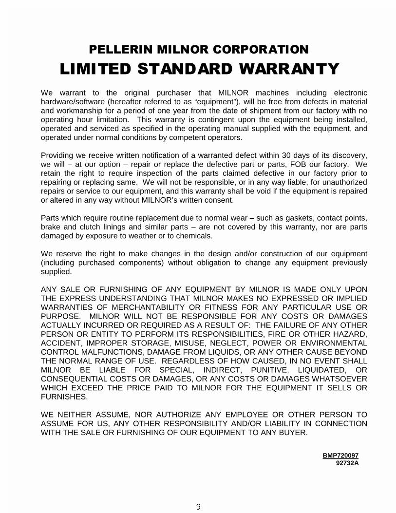
3(//(5,1�0,/125�&25325$7,21
/,0,7('�67$1'$5'�:$55$17<
We warrant to the original purchaser that MILNOR machines including electronichardware/software (hereafter referred to as “equipment”), will be free from defects in materialand workmanship for a period of one year from the date of shipment from our factory with nooperating hour limitation. This warranty is contingent upon the equipment being installed,operated and serviced as specified in the operating manual supplied with the equipment, andoperated under normal conditions by competent operators.
Providing we receive written notification of a warranted defect within 30 days of its discovery,we will – at our option – repair or replace the defective part or parts, FOB our factory. Weretain the right to require inspection of the parts claimed defective in our factory prior torepairing or replacing same. We will not be responsible, or in any way liable, for unauthorizedrepairs or service to our equipment, and this warranty shall be void if the equipment is repairedor altered in any way without MILNOR’s written consent.
Parts which require routine replacement due to normal wear – such as gaskets, contact points,brake and clutch linings and similar parts – are not covered by this warranty, nor are partsdamaged by exposure to weather or to chemicals.
We reserve the right to make changes in the design and/or construction of our equipment(including purchased components) without obligation to change any equipment previouslysupplied.
ANY SALE OR FURNISHING OF ANY EQUIPMENT BY MILNOR IS MADE ONLY UPONTHE EXPRESS UNDERSTANDING THAT MILNOR MAKES NO EXPRESSED OR IMPLIEDWARRANTIES OF MERCHANTABILITY OR FITNESS FOR ANY PARTICULAR USE ORPURPOSE. MILNOR WILL NOT BE RESPONSIBLE FOR ANY COSTS OR DAMAGESACTUALLY INCURRED OR REQUIRED AS A RESULT OF: THE FAILURE OF ANY OTHERPERSON OR ENTITY TO PERFORM ITS RESPONSIBILITIES, FIRE OR OTHER HAZARD,ACCIDENT, IMPROPER STORAGE, MISUSE, NEGLECT, POWER OR ENVIRONMENTALCONTROL MALFUNCTIONS, DAMAGE FROM LIQUIDS, OR ANY OTHER CAUSE BEYONDTHE NORMAL RANGE OF USE. REGARDLESS OF HOW CAUSED, IN NO EVENT SHALLMILNOR BE LIABLE FOR SPECIAL, INDIRECT, PUNITIVE, LIQUIDATED, ORCONSEQUENTIAL COSTS OR DAMAGES, OR ANY COSTS OR DAMAGES WHATSOEVERWHICH EXCEED THE PRICE PAID TO MILNOR FOR THE EQUIPMENT IT SELLS ORFURNISHES.
WE NEITHER ASSUME, NOR AUTHORIZE ANY EMPLOYEE OR OTHER PERSON TOASSUME FOR US, ANY OTHER RESPONSIBILITY AND/OR LIABILITY IN CONNECTIONWITH THE SALE OR FURNISHING OF OUR EQUIPMENT TO ANY BUYER.
BMP72009792732A
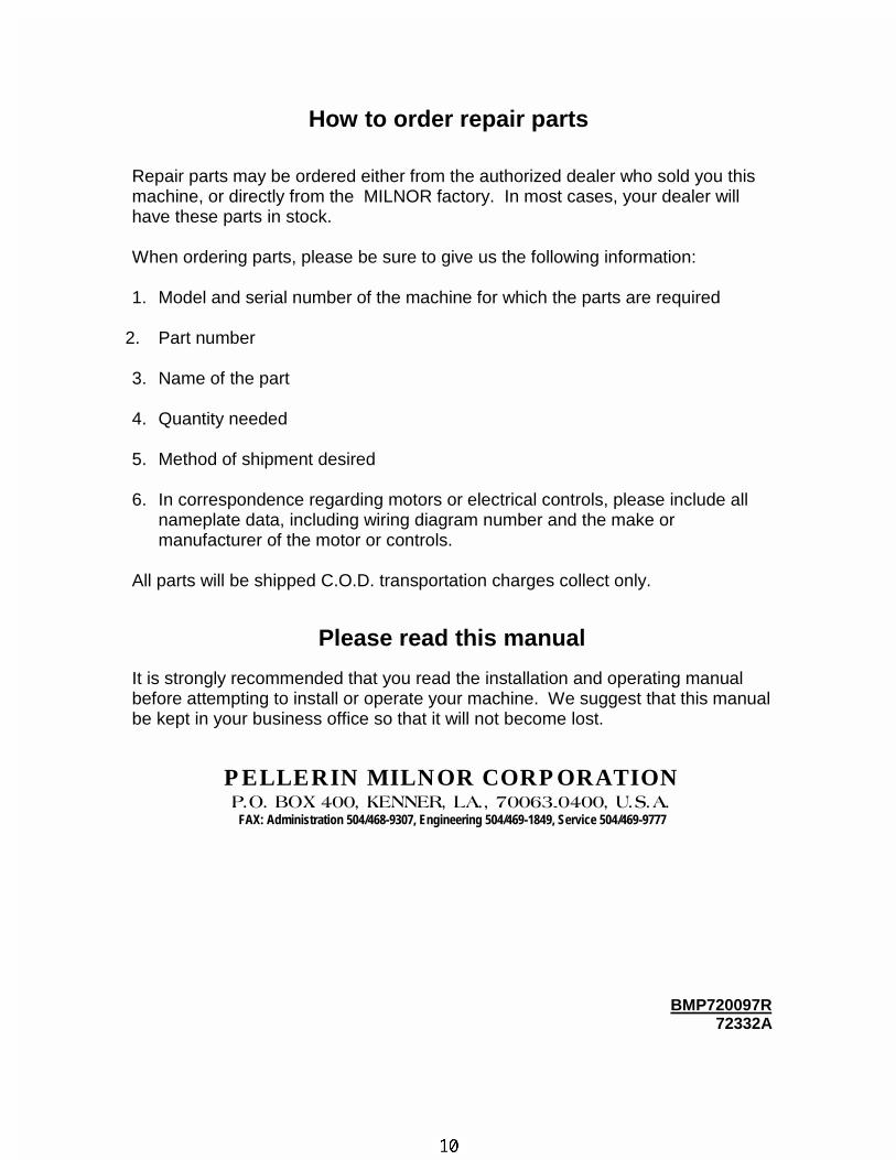
How to order repair parts
Repair parts may be ordered either from the authorized dealer who sold you thismachine, or directly from the MILNOR factory. In most cases, your dealer willhave these parts in stock.
When ordering parts, please be sure to give us the following information:
1. Model and serial number of the machine for which the parts are required
2. Part number
3. Name of the part
4. Quantity needed
5. Method of shipment desired
6. In correspondence regarding motors or electrical controls, please include allnameplate data, including wiring diagram number and the make ormanufacturer of the motor or controls.
All parts will be shipped C.O.D. transportation charges collect only.
Please read this manual
It is strongly recommended that you read the installation and operating manualbefore attempting to install or operate your machine. We suggest that this manualbe kept in your business office so that it will not become lost.
PELLERIN MILNOR CORPORATION3�2��%2;������.(11(5��/$���������������8�6�$�
FAX: Administration 504/468-9307, Engineering 504/469-1849, Service 504/469-9777
BMP720097R72332A

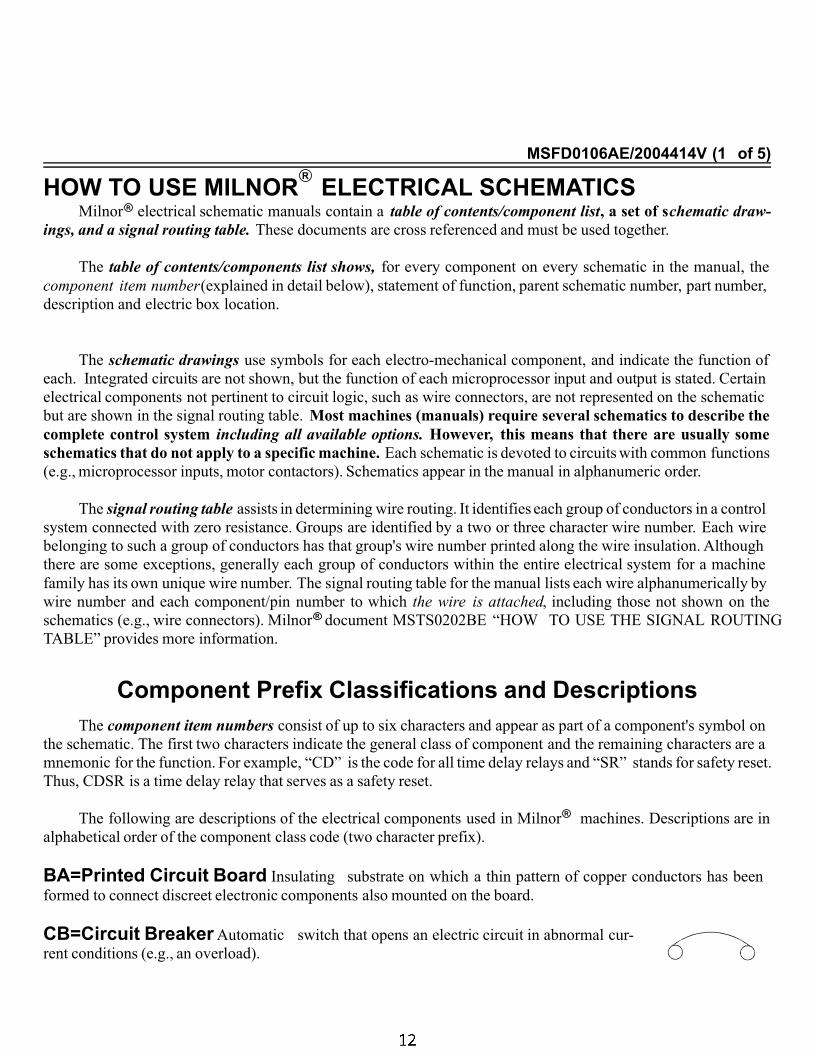
MSFD0106AE/2004414V (1 of 5)
…HOW TO USE MILNORR
R
R
ELECTRICAL SCHEMATICSMilnor electrical schematic manuals contain a table of contents/component list, a set of schematic draw-
ings, and a signal routing table. These documents are cross referenced and must be used together.
The table of contents/components list shows, for every component on every schematic in the manual, the
component item number(explained in detail below), statement of function, parent schematic number, part number,
description and electric box location.
The schematic drawings use symbols for each electro-mechanical component, and indicate the function of
each. Integrated circuits are not shown, but the function of each microprocessor input and output is stated. Certain
electrical components not pertinent to circuit logic, such as wire connectors, are not represented on the schematic
but are shown in the signal routing table. Most machines (manuals) require several schematics to describe the
complete control system including all available options. However, this means that there are usually some
schematics that do not apply to a specific machine. Each schematic is devoted to circuits with common functions
(e.g., microprocessor inputs, motor contactors). Schematics appear in the manual in alphanumeric order.
The signal routing table assists in determining wire routing. It identifies each group of conductors in a control
system connected with zero resistance. Groups are identified by a two or three character wire number. Each wire
belonging to such a group of conductors has that group's wire number printed along the wire insulation. Although
there are some exceptions, generally each group of conductors within the entire electrical system for a machine
family has its own unique wire number. The signal routing table for the manual lists each wire alphanumerically by
wire number and each component/pin number to which the wire is attached, including those not shown on the
schematics (e.g., wire connectors). Milnor document MSTS0202BE “HOW TO USE THE SIGNAL ROUTING
TABLE” provides more information.
Component Prefix Classifications and DescriptionsThe component item numbers consist of up to six characters and appear as part of a component's symbol on
the schematic. The first two characters indicate the general class of component and the remaining characters are a
mnemonic for the function. For example, “CD” is the code for all time delay relays and “SR” stands for safety reset.
Thus, CDSR is a time delay relay that serves as a safety reset.
The following are descriptions of the electrical components used in Milnor machines. Descriptions are in
alphabetical order of the component class code (two character prefix).
ÀBA=Printed Circuit Board Insulating substrate on which a thin pattern of copper conductors has been
formed to connect discreet electronic components also mounted on the board.
ÀCB=Circuit Breaker Automatic switch that opens an electric circuit in abnormal cur-
rent conditions (e.g., an overload).
R
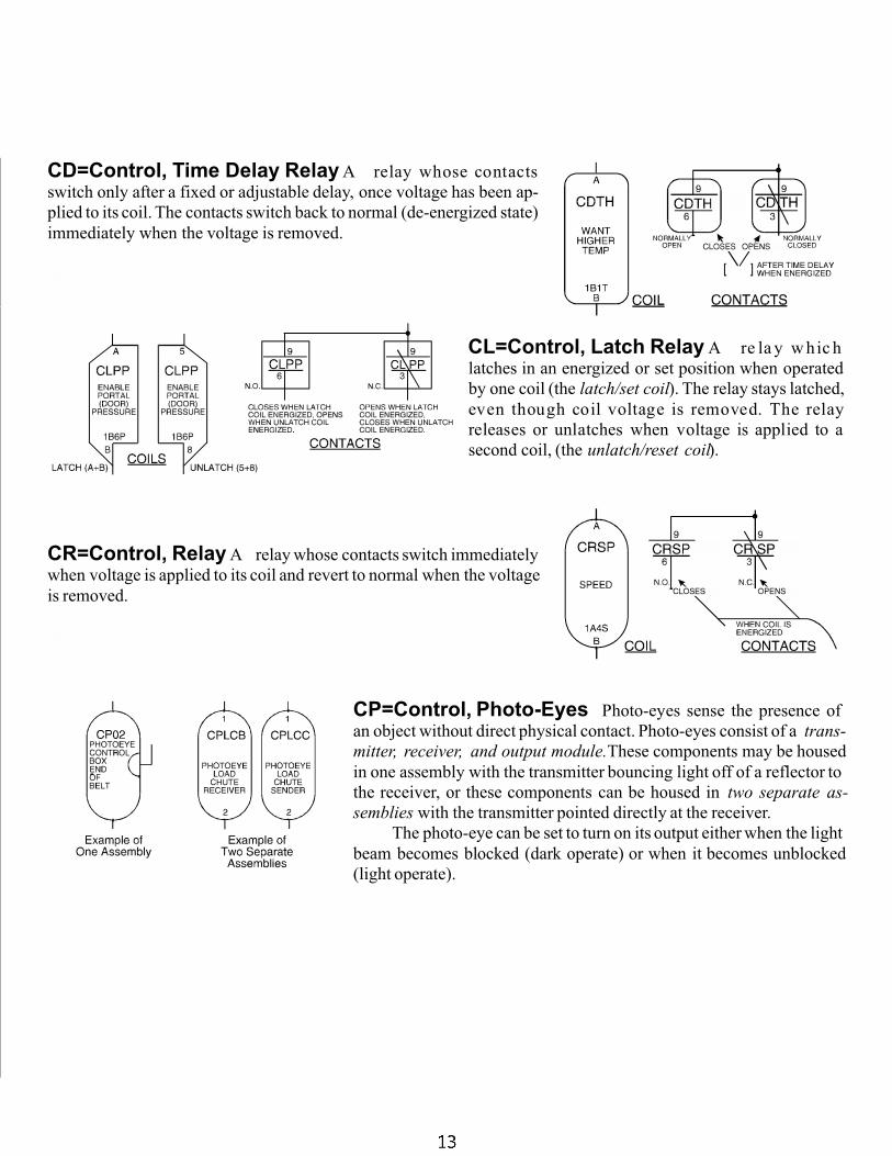
ÀCD=Control, Time Delay Relay A relay whose contacts
switch only after a fixed or adjustable delay, once voltage has been ap-
plied to its coil. The contacts switch back to normal (de-energized state)
immediately when the voltage is removed.
À
CL=Control, Latch Relay A re la y w hic h
latches in an energized or set position when operated
by one coil (the latch/set coil). The relay stays latched,
even though coil voltage is removed. The relay
releases or unlatches when voltage is applied to a
second coil, (the unlatch/reset coil).
ÀCR=Control, Relay A relay whose contacts switch immediately
when voltage is applied to its coil and revert to normal when the voltage
is removed.
À
CP=Control, Photo-Eyes Photo-eyes sense the presence of
an object without direct physical contact. Photo-eyes consist of a trans-
mitter, receiver, and output module.These components may be housed
in one assembly with the transmitter bouncing light off of a reflector to
the receiver, or these components can be housed in two separate as-
semblies with the transmitter pointed directly at the receiver.
The photo-eye can be set to turn on its output either when the light
beam becomes blocked (dark operate) or when it becomes unblocked
(light operate).
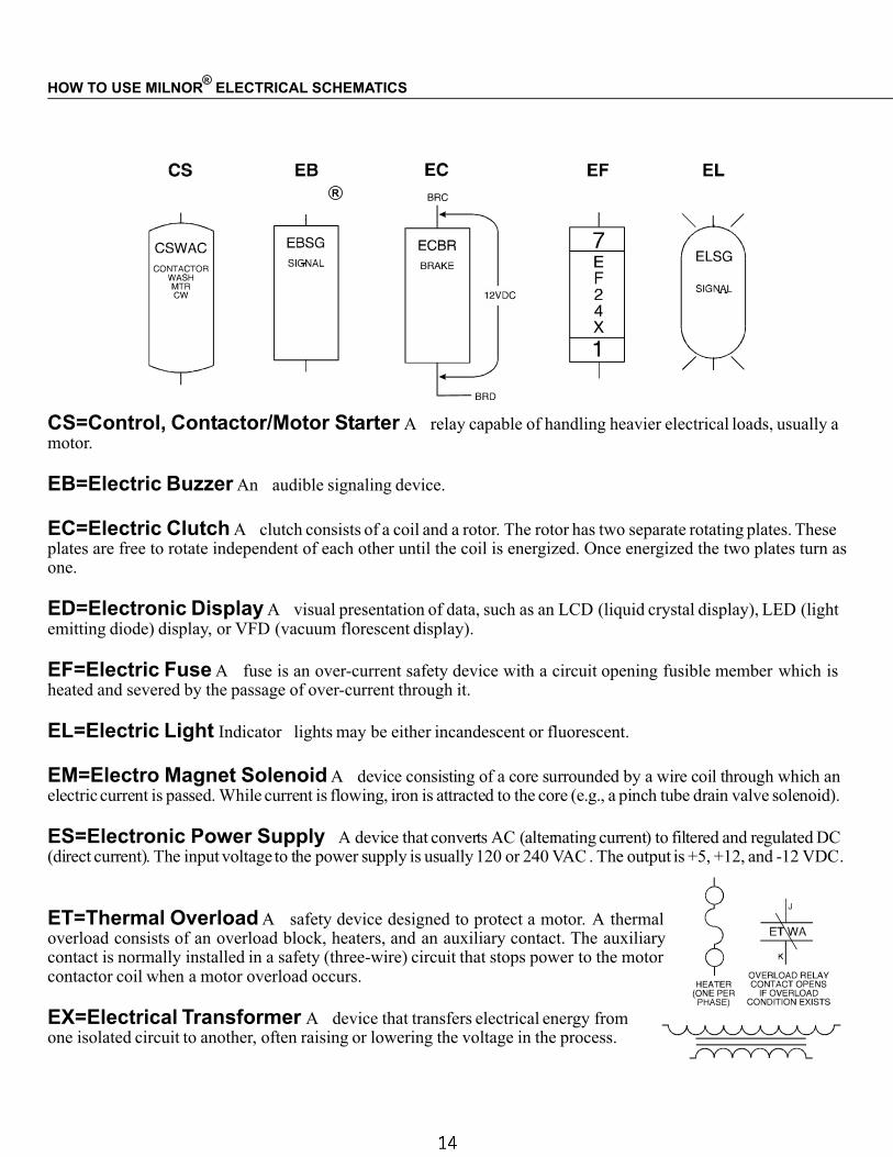
ÀCS=Control, Contactor/Motor Starter A relay capable of handling heavier electrical loads, usually amotor.
ÀEB=Electric Buzzer An audible signaling device.
ÀEC=Electric Clutch A clutch consists of a coil and a rotor. The rotor has two separate rotating plates. Theseplates are free to rotate independent of each other until the coil is energized. Once energized the two plates turn asone.
ÀED=Electronic Display A visual presentation of data, such as an LCD (liquid crystal display), LED (lightemitting diode) display, or VFD (vacuum florescent display).
ÀEF=Electric Fuse A fuse is an over-current safety device with a circuit opening fusible member which isheated and severed by the passage of over-current through it.
ÀEL=Electric Light Indicator lights may be either incandescent or fluorescent.
ÀEM=Electro Magnet Solenoid A device consisting of a core surrounded by a wire coil through which anelectric current is passed. While current is flowing, iron is attracted to the core (e.g., a pinch tube drain valve solenoid).
ÀES=Electronic Power Supply A device that converts AC (alternating current) to filtered and regulated DC(direct current). The input voltage to the power supply is usually 120 or 240 VAC . The output is +5, +12, and -12 VDC.
ÀET=Thermal Overload A safety device designed to protect a motor. A thermaloverload consists of an overload block, heaters, and an auxiliary contact. The auxiliarycontact is normally installed in a safety (three-wire) circuit that stops power to the motorcontactor coil when a motor overload occurs.
ÀEX=Electrical Transformer A device that transfers electrical energy fromone isolated circuit to another, often raising or lowering the voltage in the process.
HOW TO USE MILNOR ELECTRICAL SCHEMATICS
R
R
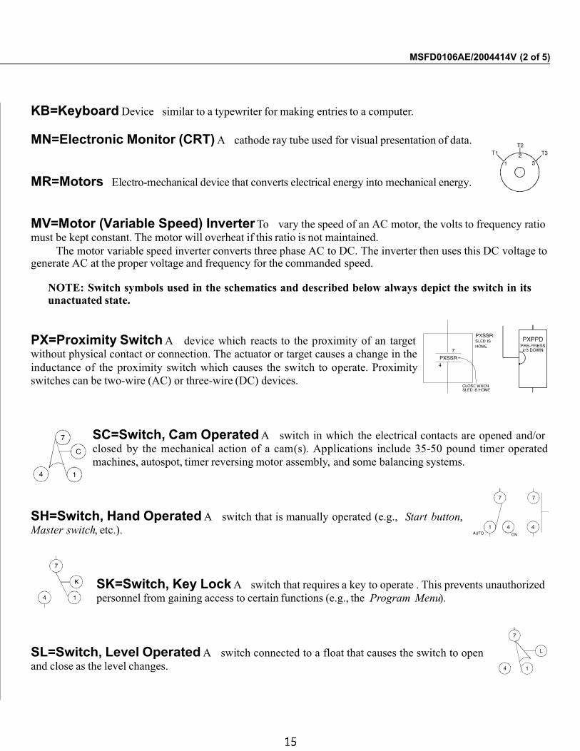
ÀKB=Keyboard Device similar to a typewriter for making entries to a computer.
ÀMN=Electronic Monitor (CRT) A cathode ray tube used for visual presentation of data.
ÀMR=Motors Electro-mechanical device that converts electrical energy into mechanical energy.
ÀMV=Motor (Variable Speed) Inverter To vary the speed of an AC motor, the volts to frequency ratio
must be kept constant. The motor will overheat if this ratio is not maintained.
The motor variable speed inverter converts three phase AC to DC. The inverter then uses this DC voltage togenerate AC at the proper voltage and frequency for the commanded speed.
NOTE: Switch symbols used in the schematics and described below always depict the switch in itsunactuated state.
ÀPX=Proximity Switch A device which reacts to the proximity of an target
without physical contact or connection. The actuator or target causes a change in the
inductance of the proximity switch which causes the switch to operate. Proximity
switches can be two-wire (AC) or three-wire (DC) devices.
ÀSC=Switch, Cam Operated A switch in which the electrical contacts are opened and/or
closed by the mechanical action of a cam(s). Applications include 35-50 pound timer operated
machines, autospot, timer reversing motor assembly, and some balancing systems.
ÀSH=Switch, Hand Operated A switch that is manually operated (e.g., Start button,
Master switch, etc.).
ÀSK=Switch, Key Lock A switch that requires a key to operate . This prevents unauthorized
personnel from gaining access to certain functions (e.g., the Program Menu).
ÀSL=Switch, Level Operated A switch connected to a float that causes the switch to open
and close as the level changes.
MSFD0106AE/2004414V (2 of 5)
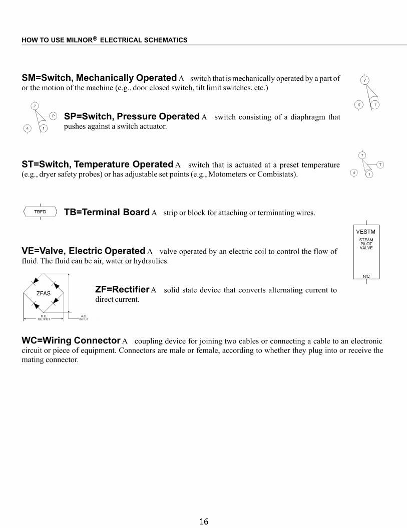
ÀSM=Switch, Mechanically Operated A switch that is mechanically operated by a part of
or the motion of the machine (e.g., door closed switch, tilt limit switches, etc.)
ÀSP=Switch, Pressure Operated A switch consisting of a diaphragm that
pushes against a switch actuator.
ÀST=Switch, Temperature Operated A switch that is actuated at a preset temperature
(e.g., dryer safety probes) or has adjustable set points (e.g., Motometers or Combistats).
ÀTB=Terminal Board A strip or block for attaching or terminating wires.
ÀVE=Valve, Electric Operated A valve operated by an electric coil to control the flow of
fluid. The fluid can be air, water or hydraulics.
ÀZF=Rectifier A solid state device that converts alternating current to
direct current.
À
WC=Wiring Connector A coupling device for joining two cables or connecting a cable to an electronic
circuit or piece of equipment. Connectors are male or female, according to whether they plug into or receive the
mating connector.
HOW TO USE MILNOR ELECTRICAL SCHEMATICSR
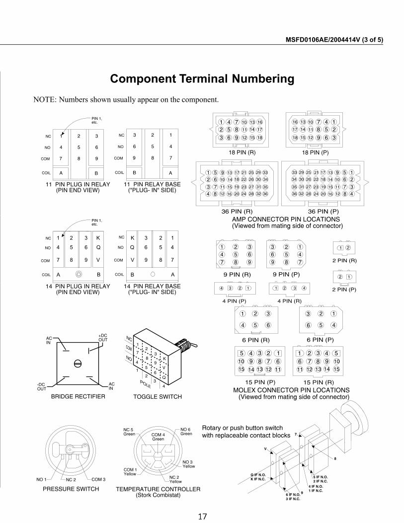
Component Terminal Numbering
NOTE: Numbers shown usually appear on the component.
MSFD0106AE/2004414V (3 of 5)
4 5 6 Q Q 6 5 4
7 8 9 V V 9 8 7
1 2 3 K K 3 2 1
A BB A
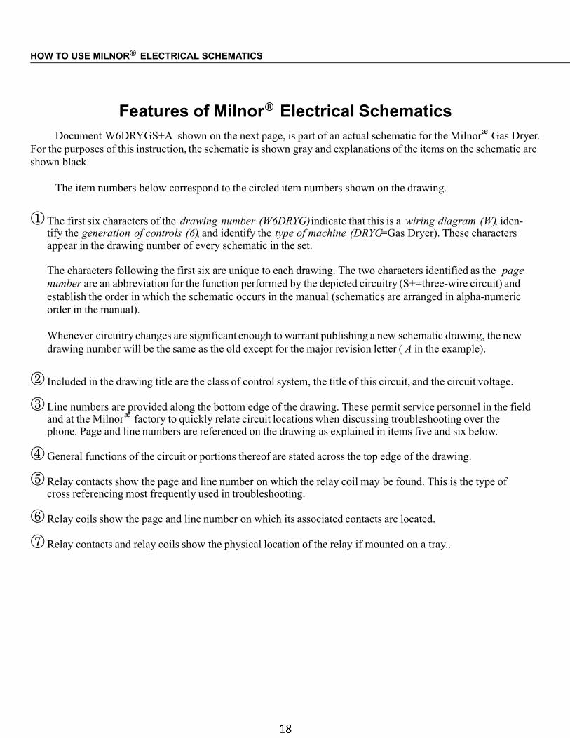
Features of Milnor R Electrical SchematicsDocument W6DRYGS+A shown on the next page, is part of an actual schematic for the Milnor
æGas Dryer.
For the purposes of this instruction, the schematic is shown gray and explanations of the items on the schematic are
shown black.
The item numbers below correspond to the circled item numbers shown on the drawing.
� The first six characters of the drawing number (W6DRYG)indicate that this is a wiring diagram (W), iden-tify the generation of controls (6), and identify the type of machine (DRYG=Gas Dryer). These charactersappear in the drawing number of every schematic in the set.
The characters following the first six are unique to each drawing. The two characters identified as the page
number are an abbreviation for the function performed by the depicted circuitry (S+=three-wire circuit) and
establish the order in which the schematic occurs in the manual (schematics are arranged in alpha-numeric
order in the manual).
Whenever circuitry changes are significant enough to warrant publishing a new schematic drawing, the new
drawing number will be the same as the old except for the major revision letter ( A in the example).
� Included in the drawing title are the class of control system, the title of this circuit, and the circuit voltage.
� Line numbers are provided along the bottom edge of the drawing. These permit service personnel in the fieldand at the Milnor
æfactory to quickly relate circuit locations when discussing troubleshooting over the
phone. Page and line numbers are referenced on the drawing as explained in items five and six below.
� General functions of the circuit or portions thereof are stated across the top edge of the drawing.
� Relay contacts show the page and line number on which the relay coil may be found. This is the type ofcross referencing most frequently used in troubleshooting.
� Relay coils show the page and line number on which its associated contacts are located.
� Relay contacts and relay coils show the physical location of the relay if mounted on a tray..
HOW TO USE MILNOR ELECTRICAL SCHEMATICSR
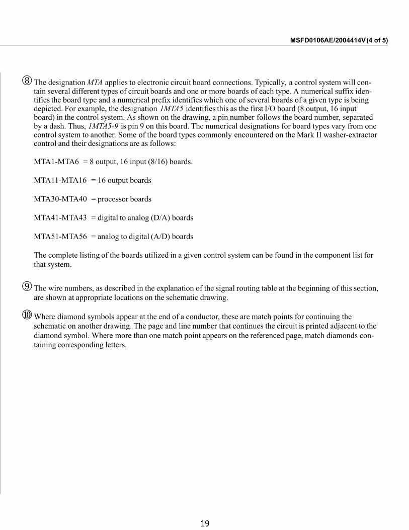
� The designation MTA applies to electronic circuit board connections. Typically, a control system will con-tain several different types of circuit boards and one or more boards of each type. A numerical suffix iden-tifies the board type and a numerical prefix identifies which one of several boards of a given type is beingdepicted. For example, the designation 1MTA5 identifies this as the first I/O board (8 output, 16 inputboard) in the control system. As shown on the drawing, a pin number follows the board number, separatedby a dash. Thus, 1MTA5-9 is pin 9 on this board. The numerical designations for board types vary from onecontrol system to another. Some of the board types commonly encountered on the Mark II washer-extractorcontrol and their designations are as follows:
MTA1-MTA6 = 8 output, 16 input (8/16) boards.
MTA11-MTA16 = 16 output boards
MTA30-MTA40 = processor boards
MTA41-MTA43 = digital to analog (D/A) boards
MTA51-MTA56 = analog to digital (A/D) boards
The complete listing of the boards utilized in a given control system can be found in the component list for
that system.
The wire numbers, as described in the explanation of the signal routing table at the beginning of this section,
are shown at appropriate locations on the schematic drawing.
Where diamond symbols appear at the end of a conductor, these are match points for continuing the
schematic on another drawing. The page and line number that continues the circuit is printed adjacent to the
diamond symbol. Where more than one match point appears on the referenced page, match diamonds con-
taining corresponding letters.
MSFD0106AE/2004414V(4 of 5)
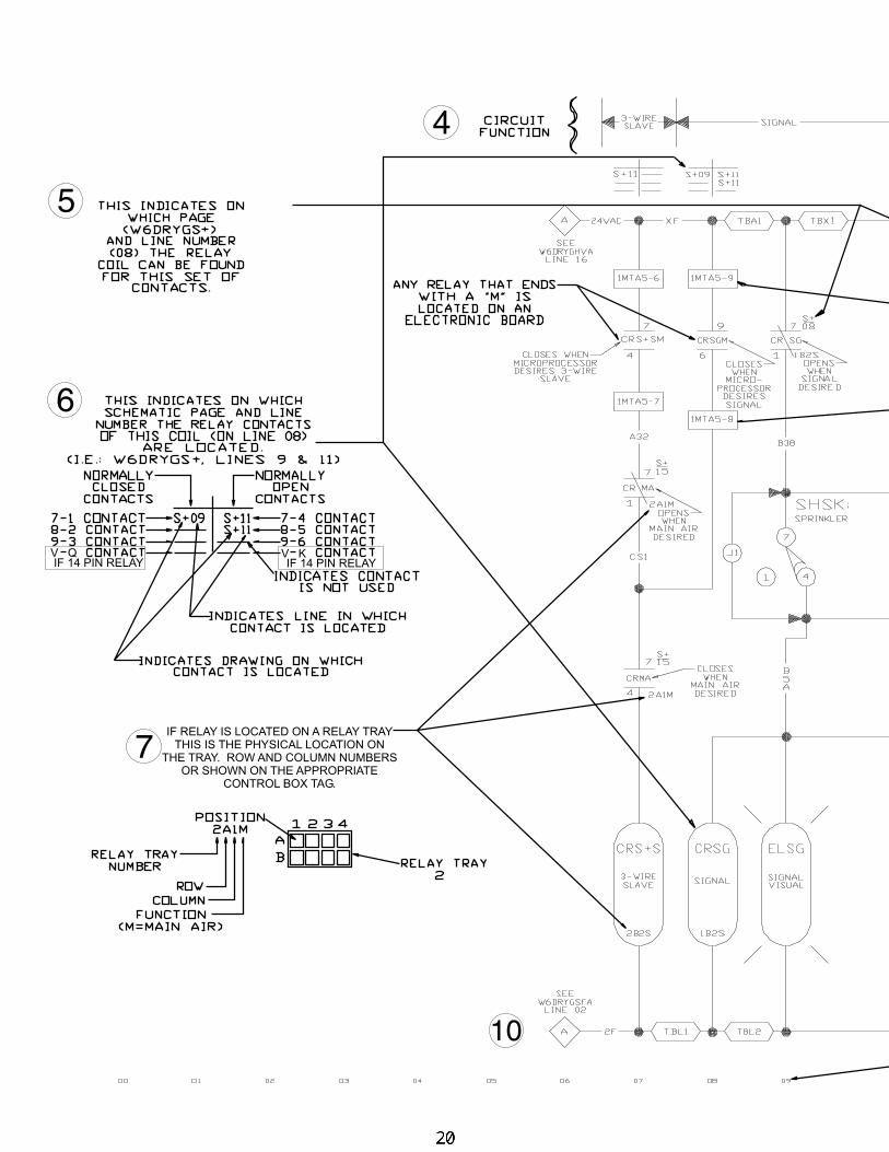
6
5
10
7
4
V Q V KIF 14 PIN RELAYIF 14 PIN RELAY
IF RELAY IS LOCATED ON A RELAY TRAY
THIS IS THE PHYSICAL LOCATION ON
THE TRAY. ROW AND COLUMN NUMBERS
OR SHOWN ON THE APPROPRIATE
CONTROL BOX TAG.
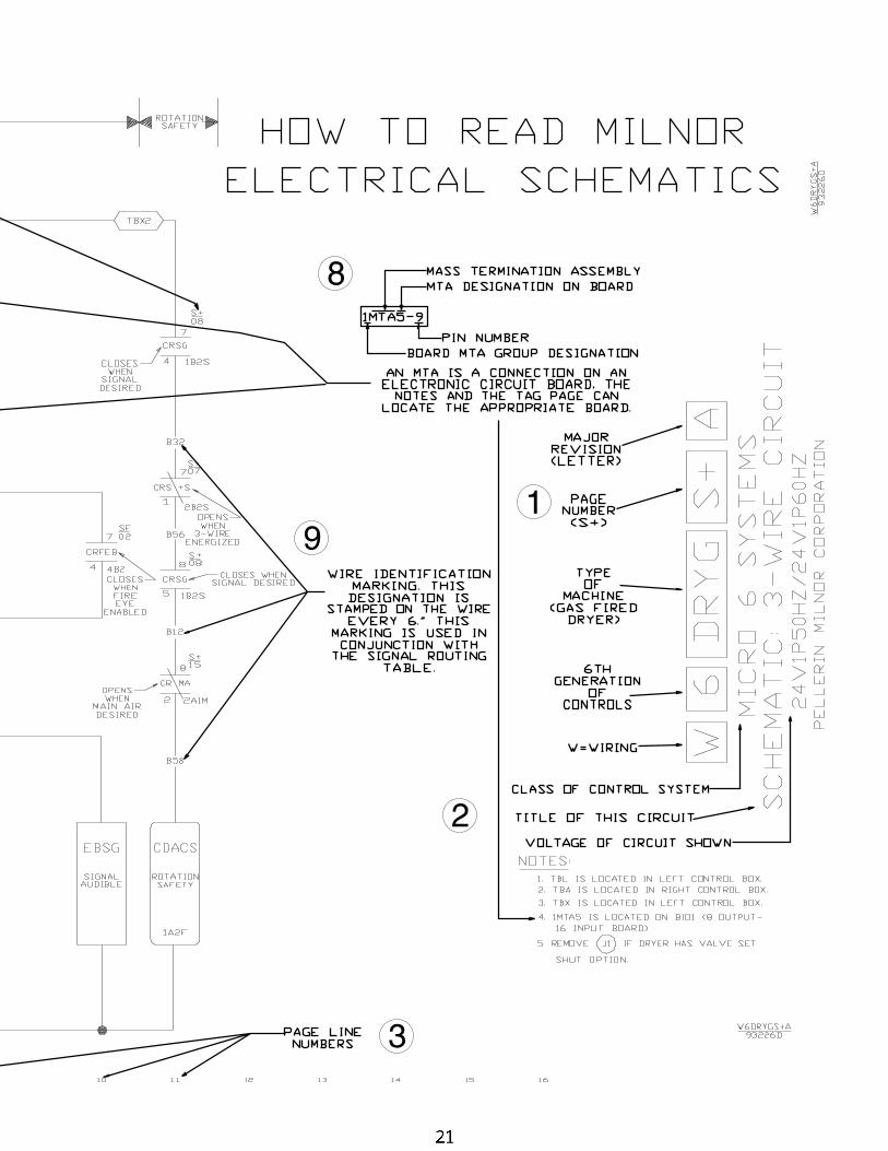
1
2
3
8
9
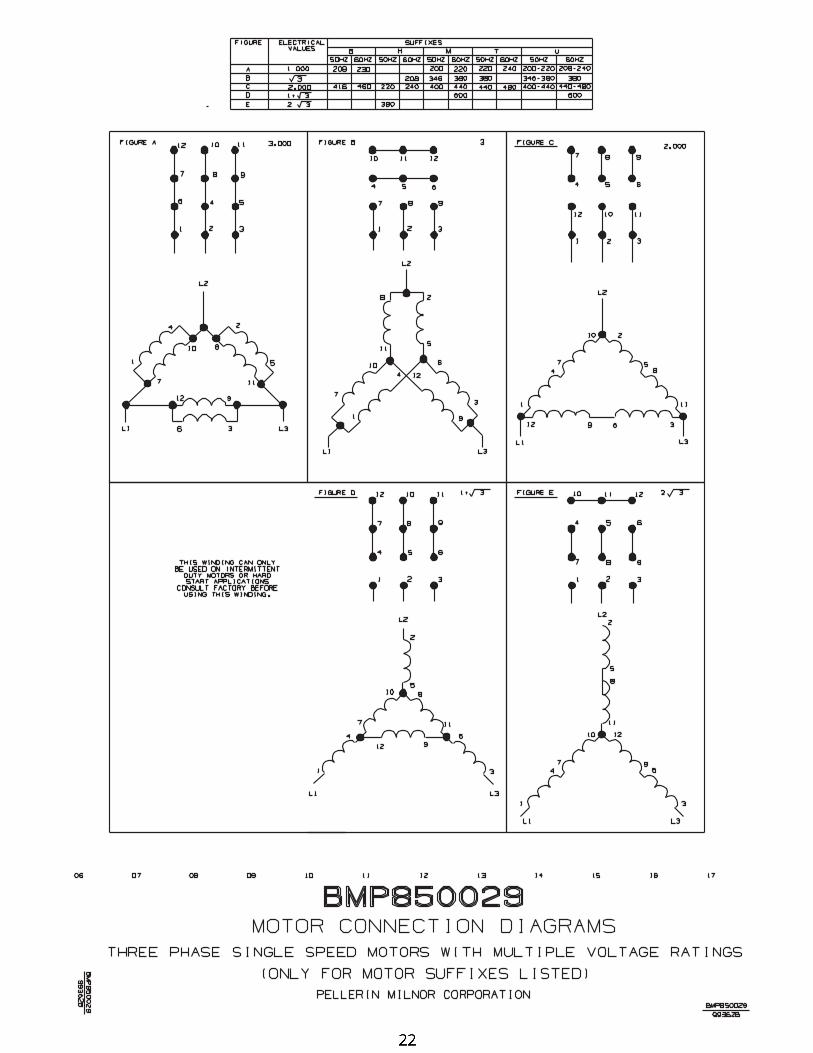
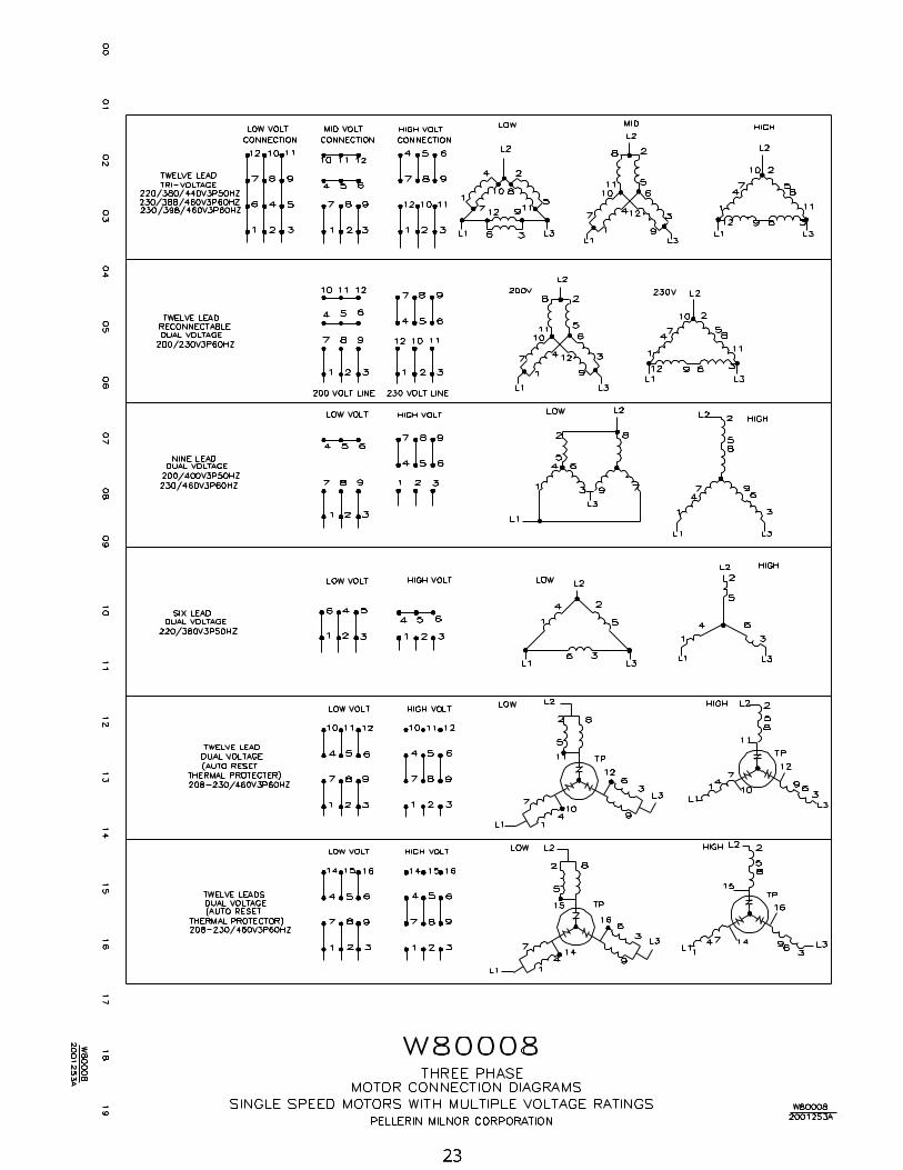
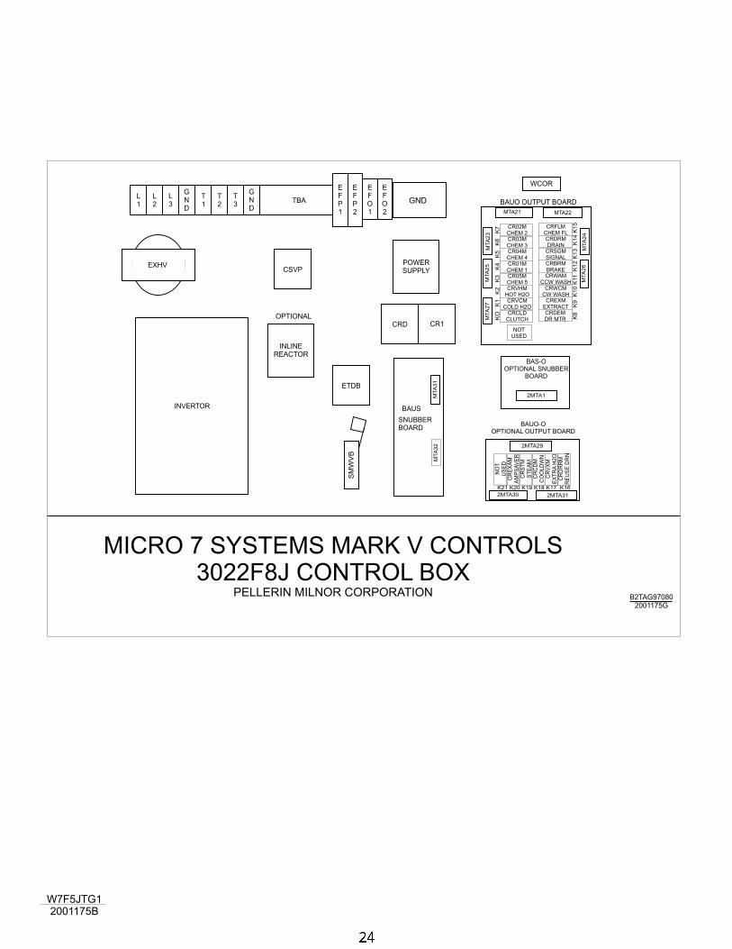
W7F5JTG1
2001175B
EXHV POWER
SUPPLY
INLINE
REACTOR
OPTIONAL
ETDB
CSVP
CRD CR1
WCOR
TBAL
1
T
1
L
3
T
3
L
2
T
2
G
N
D
G
N
D
E
F
P
1
E
F
O
1
E
F
P
2
E
F
O
2
SM
WV
B
MICRO 7 SYSTEMS MARK V CONTROLS
3022F8J CONTROL BOXPELLERIN MILNOR CORPORATION
B2TAG97080
2001175G
CR02M
CHEM 2CR03M
CHEM 3CR04M
CHEM 4CR01M
CHEM 1CR05M
CHEM 5CRVHM
HOT H2OCRVCM
COLD H2OCRCLD
CLUTCH
CRFLM
CHEM FL
NO
T
US
ED
CRDRM
DRAIN
CR
EX
AM
AM
PS
AV
ER
CRSGM
SIGNAL
CR
ST
M
ST
EA
M
CRBRM
BRAKE
CR
CD
M
CO
OLD
WN
CRWAM
CCW WASH
CR
VX
M
EX
TR
AH
2O
CRWCM
CW WASH
CR
DR
RM
RE
US
ED
RN
CRDEM
DR MTR
CREXM
EXTRACT
NOT
USED
BAUO OUTPUT BOARD
MTA
27
MTA
32
MTA
25
MTA
31
MTA
26
MTA
23
MTA
24
MTA21
2MTA30
MTA22
2MTA31
2MTA29
2MTA1
BAUS
SNUBBER
BOARD
INVERTOR
GND
KO
K1
K2
K3
K4
K5
K6
K7
K8
K9
K1
0K
11
K12
K13
K14
K15
K21 K20 K19 K18 K17 K16
BAUO-O
OPTIONAL OUTPUT BOARD
BAS-O
OPTIONAL SNUBBER
BOARD
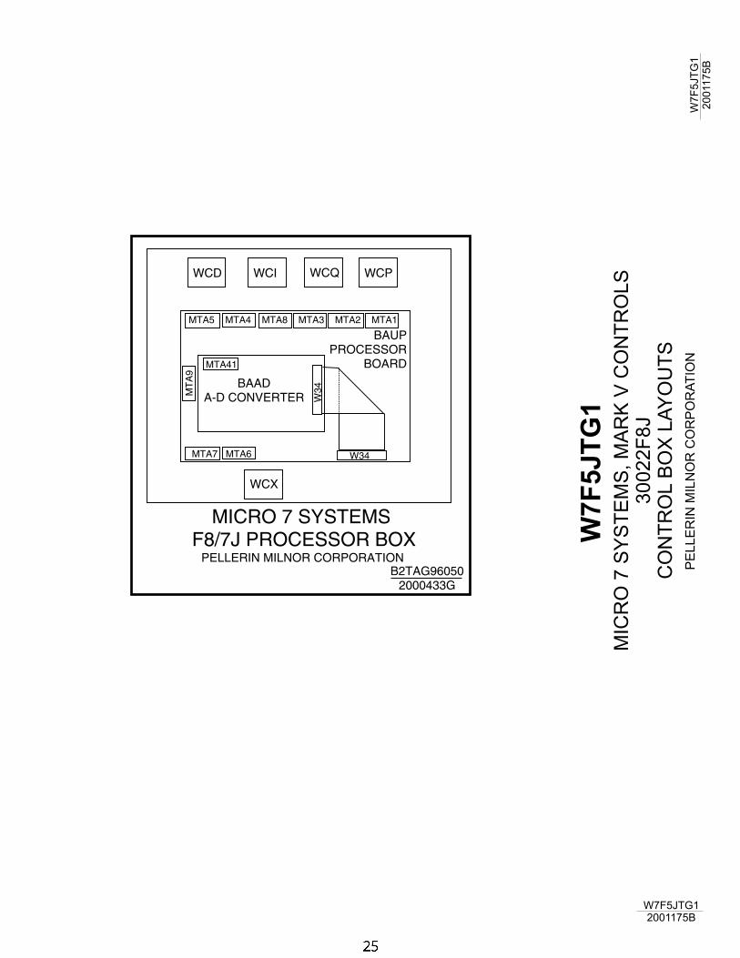
W7
F5
JT
G1
MIC
RO
7S
YS
TE
MS
,M
AR
KV
CO
NT
RO
LS
30
02
2F
8J
CO
NT
RO
LB
OX
LA
YO
UT
S
PE
LLE
RIN
MIL
NO
RC
OR
PO
RA
TIO
N
W7F5JTG1
2001175B
W7
F5
JT
G1
20
011
75
B
WCD
WCX
WCQWCI WCP
B2TAG96050
2000433G
MICRO 7 SYSTEMS
F8/7J PROCESSOR BOXPELLERIN MILNOR CORPORATION
MTA7 MTA6
MTA41
MT
A9
W3
4
W34
MTA5 MTA4 MTA8 MTA3 MTA2 MTA1
BAAD
A-D CONVERTER
BAUP
PROCESSOR
BOARD
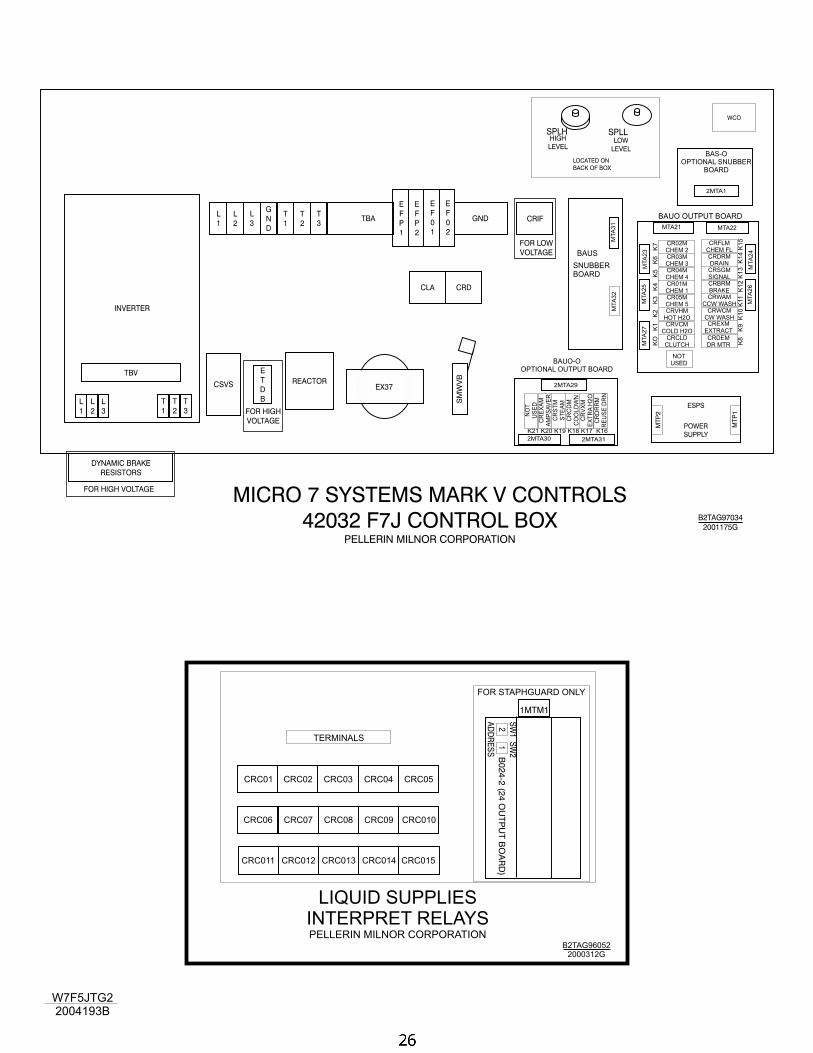
W7F5JTG2
2004193B
E
T
D
B
CSVS EX37REACTOR
CLA CRD
CRIF
INVERTER
L
1
T
1L
2
T
2L
3
T
3
TBV
FOR HIGH VOLTAGE
FOR HIGH
VOLTAGE
FOR LOW
VOLTAGE
DYNAMIC BRAKE
RESISTORS
TBAL
1
T
1
L
3
T
3
L
2
T
2
G
N
D
GND
E
F
0
1
E
F
P
1
E
F
0
2
E
F
P
2
SM
WV
B
MICRO 7 SYSTEMS MARK V CONTROLS
42032 F7J CONTROL BOXPELLERIN MILNOR CORPORATION
B2TAG97034
2001175G
WCO
LOCATED ON
BACK OF BOX
POWER
SUPPLY
ESPS
SPLH SPLLLOW
LEVEL
HIGH
LEVEL
MT
P2
MT
P1
CR02M
CHEM 2CR03M
CHEM 3CR04M
CHEM 4CR01M
CHEM 1CR05M
CHEM 5CRVHM
HOT H2OCRVCM
COLD H2OCRCLD
CLUTCH
CRFLM
CHEM FL
NO
T
US
ED
CRDRM
DRAIN
CR
EX
AM
AM
PS
AV
ER
CRSGM
SIGNAL
CR
ST
M
ST
EA
M
CRBRM
BRAKE
CR
CD
M
CO
OLD
WN
CRWAM
CCW WASH
CR
VX
M
EX
TR
AH
2O
CRWCM
CW WASH
CR
DR
RM
RE
US
ED
RN
CRDEM
DR MTR
CREXM
EXTRACT
NOT
USED
BAUO OUTPUT BOARD
MTA
27
MTA
32
MTA
25
MTA
31
MTA
26
MTA
23
MTA
24
MTA21
2MTA30
MTA22
2MTA31
2MTA29
2MTA1
BAUS
SNUBBER
BOARD
KO
K1
K2
K3
K4
K5
K6
K7
K8
K9
K1
0K
11
K1
2K
13
K1
4K
15
K21 K20 K19 K18 K17 K16
BAUO-O
OPTIONAL OUTPUT BOARD
BAS-O
OPTIONAL SNUBBER
BOARD
LIQUID SUPPLIES
INTERPRET RELAYSPELLERIN MILNOR CORPORATION
B2TAG96052
2000312G
TERMINALS
FOR STAPHGUARD ONLY
CRC01 CRC03CRC02 CRC05CRC04
CRC08 CRC010CRC06 CRC09CRC07
CRC013CRC012CRC011 CRC015CRC014
1MTM1
B0
24
-2(2
4O
UT
PU
TB
OA
RD
)
SW
1S
W2
AD
DR
ES
S
12
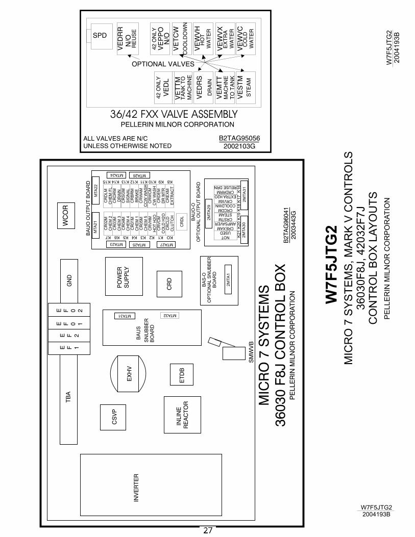
W7
F5
JT
G2
MIC
RO
7S
YS
TE
MS
,M
AR
KV
CO
NT
RO
LS
36
03
0F
8J,
42
03
2F
7J
CO
NT
RO
LB
OX
LA
YO
UT
S
PE
LLE
RIN
MIL
NO
RC
OR
PO
RA
TIO
N
W7F5JTG2
2004193B
W7F
5JT
G2
2004193B
B2TAG95056
2002103G
36/42 FXX VALVE ASSEMBLYPELLERIN MILNOR CORPORATION
ALL VALVES ARE N/C
UNLESS OTHERWISE NOTED
VE
WV
XE
XT
RA
WA
TE
R
VE
ST
M
ST
EA
M
VE
MT
TM
AC
HN
E
TO
TA
NK
VE
DR
R
N/O
RE
US
E
VE
PP
O
42
ON
LY
42
ON
LY
VE
WV
HH
OT
WA
TE
R
VE
DL
VE
WV
CC
OL
D
WA
TE
R
VE
TC
W
CO
OL
DO
WN
VE
DR
S
DR
AIN
VE
TT
MT
AN
KT
O
MA
CH
INE
N/OSPD
OPTIONAL VALVES
MIC
RO
7S
YS
TE
MS
36
03
0F
8J
CO
NT
RO
LB
OX
PE
LLE
RIN
MIL
NO
RC
OR
PO
RA
TIO
NB
2TA
G9
60
41
20
03
44
3G
TB
AE F 1
E F 2
E F 0 1
E F 0 2
GN
D
EX
HV
INLIN
E
RE
AC
TO
R
CR
D
CS
VP
INV
ER
TE
R
ET
DB
SM
WV
B
PO
WE
R
SU
PP
LY
WC
OR
CR
02
M
CH
EM
2C
R0
3M
CH
EM
3C
R0
4M
CH
EM
4C
R0
1M
CH
EM
1C
R0
5M
CH
EM
5C
RV
HM
HO
TH
2O
CR
VC
M
CO
LD
H2
OC
RC
LD
CL
UT
CH
CR
DL
M
CH
EM
FL
NOT
USED
CR
DR
M
DR
AIN
CREXAM
AMPSAVER
CR
SG
M
SIG
NA
L
CRSTM
STEAM
CR
BR
M
BR
AK
E
CRCDM
COOLDWNCR
WA
M
CC
WW
AS
H
CRVXM
EXTRAH2O
CR
WC
M
CW
WA
SH
CRDRRM
REUSEDRN
CR
DE
M
DR
MT
RC
RE
XM
EX
TR
AC
T
CR
DL
BA
UO
OU
TP
UT
BO
AR
D
MTA27
MTA32
MTA25
MTA31
MTA26
MTA23
MTA24
MTA
21
2M
TA
30
MTA
22
2M
TA
31
2M
TA
29
2M
TA
1
BA
US
SN
UB
BE
R
BO
AR
D
KOK1K2K3K4K5K6K7
K8K9K10K11K12K13K14K15
K2
1K
20
K1
9K
18
K1
7K
16
BA
UO
-O
OP
TIO
NA
LO
UT
PU
TB
OA
RD
BA
S-O
OP
TIO
NA
LS
NU
BB
ER
BO
AR
D
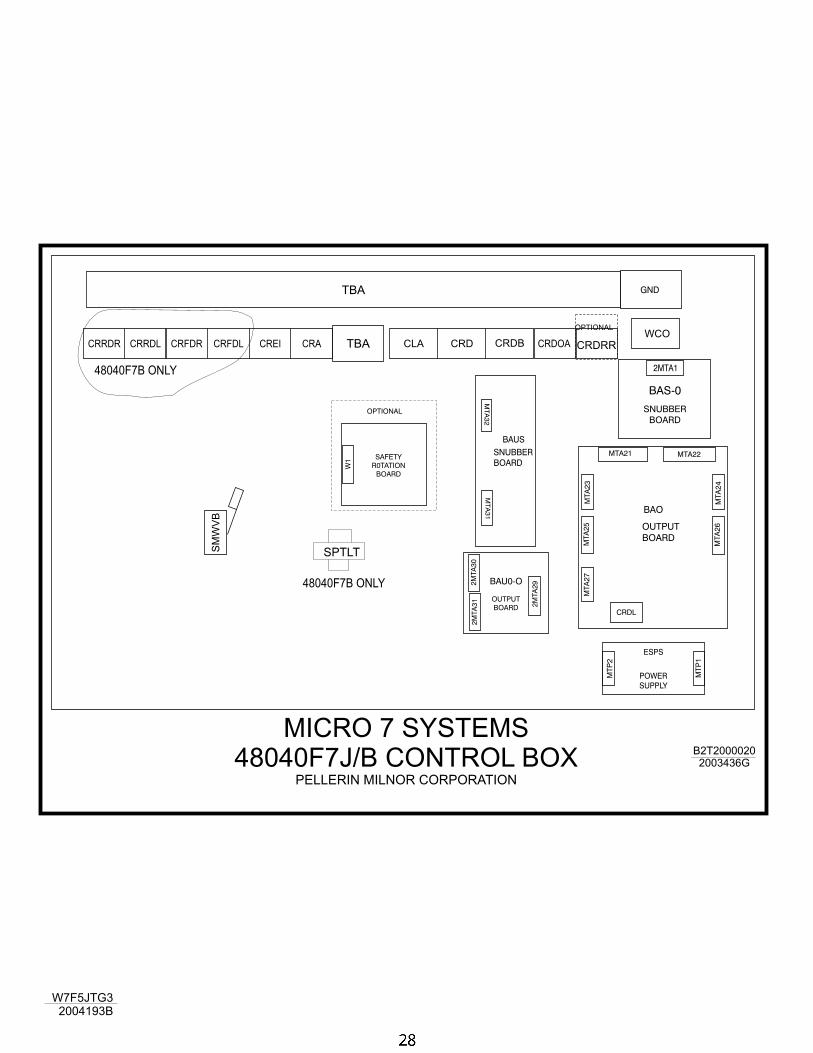
W7F5JTG3
2004193B
MICRO 7 SYSTEMS
48040F7J/B CONTROL BOXPELLERIN MILNOR CORPORATION
B2T2000020
2003436G
CRA CRDOACRD CRDBWCO
CRFDL CREICRRDR CRRDL CRFDR CLA
SM
WV
B
TBA
TBA
SPTLT
GND
MTA
32
MTA
31
BAUS
SNUBBER
BOARD
POWER
SUPPLY
ESPS
OUTPUT
BOARD
SAFETY
R0TATION
BOARD
OPTIONAL
BAU0-O
2M
TA
31
W1
2M
TA
30
2M
TA
29
CRDL
BAO
OUTPUT
BOARD
MTA
27
MT
P2
MT
P1
MTA
25
MTA
26
MTA
23
MTA
24
MTA21 MTA22
BAS-0
SNUBBER
BOARD
2MTA148040F7B ONLY
48040F7B ONLY
CRDRR
OPTIONAL
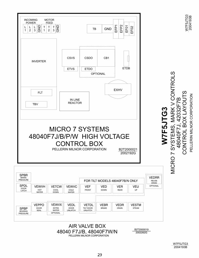
W7
F5
JT
G3
MIC
RO
7S
YS
TE
MS
,M
AR
KV
CO
NT
RO
LS
48
04
0F
7J,
42
03
2F
7B
CO
NT
RO
LB
OX
LA
YO
UT
S
PE
LLE
RIN
MIL
NO
RC
OR
PO
RA
TIO
N
W7F5JTG3
2004193B
W7F
5JT
G3
2004193B
MICRO 7 SYSTEMS
48040F7J/B/P/W HIGH VOLTAGE
CONTROL BOXPELLERIN MILNOR CORPORATION
L
1
T
1
L
2
T
2
L
3
T
3TB
EXHV
INVERTER
FLT
TBV
ETDB
CSVS CB1
OPTIONAL
CSDO
IN LINE
REACTOR
ETVS ETDO
GN
D
GN
D
EF
P1
EF
01
EF
P2
EF
02
GND
INCOMING
POWER
MOTOR
FEED
B2T2000021
2002192G
PELLERIN MILNOR CORPORATION
B2T2000019
2002262G
AIR VALVE BOX
48040 F7J/B, 48040F7W/N
SPBR
SPDL
SPBP
VEWVHHOT
WATER
VEUUP
VETCWCOOL
DOWN
VEWVXEXTRA
WATER
OPTIONAL
VERREAR
VEPPODOOR
SEAL
VEDDOWN
VEWVCCOLD
WATER
VEFFRONT
VEDLDOOR
UNLATCH
VEDRDRAIN
FOR TILT MODELS 48040F7B/N ONLY
VEBRBRAKE
VETDLTILT DOOR
UNLATCH
VESTMSTEAM
VEDRRREUSE
DRAIN
OPTIONAL
DOOR
LATCH
BRAKE
PRESSURE
BEARING
PRESSURE