Embed Size (px)
Citation preview

5/25/2016 PP MNL0027 rev E
OPERATOR’S MANUAL
This manual provides information on installation, operating, maintenance, trouble shooting & replacement parts for
3000 SERIES
ELECTRIC HOT FOOD
HOLDING UNIT
3300/3500/3600
NOTIFY CARIER OF DAMAGE AT ONCE. It is the responsibility of the consignee to inspect the container upon receipt of same and to determine the possibility of any damage, including concealed damage. Randell suggests that if you are suspicious of damage to make a notation on the delivery receipt. It will be the responsibility of the consignee to file a claim with the carrier. We recommend that you do so at once.
525 South Coldwater Rd • Weidman, MI 48893
888-994-7636 • Fax 888-864-7636 • unifiedbrands.net

2 888-994-7636
Table of Contents
page 2………………………………….…………Congratulations
page 3……………………………………Parts & Service Hotline
page 3………………………………...…Serial Number Location
page 4-7……………………………….Randell Limited Warranty
page 8…………………………………..3300 Unit Specifications
page 9………………………....3500 & 3600 Unit Specifications
page 10……………………………………………Unit Installation
page 11….....……………………………………...Unit Operation
page 12-13……………………………..Preventive Maintenance
page 14…………………………………3300 Electrical Diagram
page 15………………………..3512 & 3612 Electrical Diagram
page 16………………………..3513 & 3613 Electrical Diagram
page 17………………………..3514 & 3614 Electrical Diagram
page 18………………………..3515 & 3615 Electrical Diagram
page 19……………………………………..……Troubleshooting
page 20…………………………….…..3300 Replacement Parts
page 21………………………………...3500 Replacement Parts
page 22………………………………...3600 Replacement Parts
page 23-25………………………………Replacement Parts List
page 26……………………………….NEMA Plug Configuration
Congratulations on your recent purchase of Randell food service equipment, and we welcome you to the growing family of satisfied Randell customers. Our reputation for superior products is the result of consistent quality craftsmanship. From the earliest stages of product design to successive steps in fabrication and assembly, rigid standards of excellence are maintained by our staff of designers, engineers, and skilled employees. Only the finest heavy-duty materials and parts are used in the production of Randell brand equipment. This means that each unit, given proper maintenance will provide years of trouble free service to its owner.

unifiedbrands.net 3
In addition, all Randell food service equipment is backed by some of the best warranties in the food service ind ustry and by our professional staff of service technicians. Retain this manual for future reference. NOTICE: Due to a continuous program of product improvement, Randell
reserves the right to make changes in design and specifications without prior
notice.
NOTICE: Please read the entire manual carefully before installation. If certain
recommended procedures are not followed, warranty claims will be denied.
MODEL NUMBER _________________________
SERIAL NUMBER _________________________
INSTALLATION DATE _____________________
The serial number is located on the control panel.
888-994-7636 Randell Service and Parts Hotline

4 888-994-7636
Congratulations on your purchase of a Randell Manufactured piece of equipment. Unified Brands believes strongly in the products it builds and backs them with the best warranty in the industry. Standard with every unit is the peace of mind that this unit has been thoroughly engineered, properly tested and manufactured to excruciating tolerances, by a manufacturer with over 30 years of industry presence. On top of that front end commitment, Unified Brands has a dedicated staff of certified technicians that monitor our own technical service hotline at 1-888-994-7636 to assist you with any questions or concerns that may arise after delivery of your new Randell equipment. PARTS WARRANTY 1. One year parts replacement of any and all parts that are found defective in material or workmanship. Unified Brands warrants all component parts of manufactured new equipment to be free of defects in material or workmanship, and that the equipment meets or exceeds reasonable industry standards of performance for a period of one year from the date of shipment from any Randell factory, assembly plant or warehouse facility. NOTE: warranties are effective from date of shipme nt, with a thirty day window to allow for shipment, installation and set- up. In the event equipment was shipped to a site other than the fina l installation site, Unified Brands will warranty for a period of three months following installation, with proof of starting date, up to a maximum of fifteen months from the date of purchase. 2. Free ground freight of customer specified location for all in warranty parts within continental U.S. Component part warranty does not cover glass breakage or gasket replacement. Unified Brands covers all shipping cost related to component part warranty sent at regular ground rates (UPS, USPS). Freight or postage incurred for any express or spec ialty methods of shipping are the responsibility of the customer. LABOR COVERAGE In the unlikely event a Randell brand unit fails due to defects in materials or workmanship within the first ninety days, Unified Brands agrees to pay the contracted labor rate performed by an Authorized Service Agent (ASA). Any warranty work performed by a non-ASA will not be honored by Unified Brands. Please consult Randell Technical Support for a complete listing of ASAs. A complete listing of ASAs may also be found on the Randell page of our web site at www.unifiedbrands.net . Warranties are effective from date of shipment, with a thirty day window to allow for shipment, installation and setup. Where equipment is shipped to any site other than final installation, Unified Brands will honor the labor warranty for a period of ninety days following installation with proof of starting date, up to a maximum of six months from date of purchase.
Warranty Policies

unifiedbrands.net 5
Temperature adjustments are not covered under warra nty, due to the wide range of ambient conditions. To inquire if the equipment is within warranty, call our Field Service Department at: 1-888-994-7636. WHEN OPTIONAL LABOR EXTENSION POLICY APPLIES Unified Brands will provide reimbursement of labor invoiced to an ASA for any customer that has an optional labor extension of our standard warranty. (Contracted rates do apply) Randell offers both 1 and 2 year extensions. Labor extensions begin at the end of our standard warranty and extend out 9 months to 1 calendar year or 21 months to 2 calendar years from date of purchase. Please contact Randell technical service hotline at 1-888-994-7636 for details and any question on Authorized Service Agents (ASA). WHEN EXPORT WARRANTIES APPLY
1. Unified Brands covers all non-electrical components under the same guidelines as our standard domestic policy.
2. All electrical components operated on 60 cycle power are covered under our standard domestic policy.
3. All electrical components operated on 50 cycle power are covered for 90 days from shipment only.
4. Extended warranty options are not available from the factory. ITEMS NOT COVERED UNDER WARRANTY
1. Maintenance type of repairs such as temperature adjustments, clogged drains, and unit leveling. NOTICE: FOOD LOSS IS NOT COVERED UNDER WARRANTY
2. Repairs caused by abuse such as broken glass, freight damage, or
scratches and dents. 3. Electrical component failure due to water damage from cleaning
procedures. 4. Electrical component failure due to incorrect voltage supplied to unit. 5. Pan failures due to adding water to empty pan that is at holding
temperature. 6. Pan failures due to poor water quality.
QUOTATIONS Verbal quotations are provided for customer convenience only and are considered invalid in the absence of a written quotation. Written quotations from Randell are valid for 30 days from quote date unless otherwise specified. Randell assumes no liability for dealer quotations to end-users.

6 888-994-7636
SPECIFICATION & PRODUCT DESIGN Due to continued product improvement, specification and product design may change without notice. Such revisions do not entitle the buyer to additions. Changes or replacements for previously purchased equipment. SANITATION REQUIREMENTS Certain areas require specific annotation requirements other than N.S.F. & U.L. standards. Randell must be advised of these specifications before fabrication of equipment. In these special circumstances, a revised quotation may be required to cover additional costs. Failure to notify Randell before fabrication holds the dealer accountable for all additional charges. CANCELLATIONS Orders canceled prior to production scheduling entered into engineering/production and cancelled are subject to a cancellation charge (contact factory for details). STORAGE CHARGES Randell makes every effort to consistently meet our customer’s shipment expectations. If after the equipment has been fabricated, the customer requests delay in shipment, and warehousing is required:
1. Equipment held for shipment at purchasers request for a period of 30 days beyond original delivery date specified will be invoiced and become immediately payable.
2. Equipment held beyond 30 days after the original delivery date specified will also include storage charges.
SHIPPING & DELIVERY Randell will attempt to comply with any shipping, routing or carrier request designated by dealer, but reserves the right to ship merchandise via any responsible carrier at the time equipment is ready for shipment. Randell will not be held responsible for any carrier rate differences; rate differences are entirely between the carrier and purchaser. Point of shipping shall be determined by Randell (Weidman, MI/Jackson, MS). At dealer’s request, Randell will endeavor whenever practical to meet dealer’s request. Freight charges to be collect unless otherwise noted. DAMAGES All crating conforms to general motor carrier specifications. To avoid concealed damage, we recommend inspection of every carton upon receipt. In the event the item shows rough handling or visible damage to minimize liability, a full inspection is necessary upon arrival. Appearance of damage will require removing the crate in the presence of the driver. A notation must be placed on the freight bill and signed for by the tr uck driver at the time of delivery. Any and all freight damage that occurs to a Randell piece of equipment as a result of carrier handling is not considered under warranty, and is not covered under warranty guidelines. Any freight damage incurred during shipping needs to have a freight claim filed by the receiver with the shipping carrier. Consignee is responsible for filing of freight claims when a clear delivery receipt is signed. Claims for damages must be filed immediately (within 10 days) by the consignee with the freight carrier and all cartons and merchandise must be retained for inspection.

unifiedbrands.net 7
RETURNED GOODS Authorization for return must first be obtained from Randell before returning any merchandise. Any returned goods shipment lacking the return authorization number will be refused, all additional freight costs to be borne by the returning party. Returned equipment must be shipped in original carton, freight prepaid and received in good conditions. Any returned merchandise is subject to a minimum handling charge (consult factory for rate). INSTALLATION Equipment installation is the responsibility of the dealer and/or their customer. Randell requires all equipment to be professionally installed. PENALTY CLAUSES Dealer penalty clauses, on their purchase order or contractually agreed to between the dealer and their clients are not binding on Randell. Randell does not accept orders subject to penalty clauses. This agreement supersedes any such clauses in dealer purchase orders. EXPORT POLICY All quotations for export sales will be handled by Unified Brands’ export management organization. *FOOTNOTES IN REFERENCE TO PARAGRAPHS ABOVE 1. Herein called Randell. 2. NET means list price less discount, warranty, labor policy, freight, Randell delivery and other miscellaneous charges. CASH DISCOUNTS WILL BE CALCULATED ON NET ONLY.

8 888-994-7636
Unit Specifications
3313 shown
3300 SERIES - COMMON WATERBATH
NOTE: All 3300 series units require 1” to 2” of wat er be added PRIOR to heating of the elements. Hot water is recommended.
Model L D H # Wells
# Elements
SS Bottom Shelf Sq. Ft.
208V 240V Ship Wt.
KW Amps NEMA KW Amps NEMA
3312 33” 30” 36” 2 1 5.5 3 14.4 6-20P 3 12.5 6-20P 116
3313 48” 30” 36” 3 1 8.1 3 14.4 6-20P 3 12.5 6-20P 174
3314 63” 30” 36” 4 2 10.7 6 28.8 6-50P 6 25 6-50P 232
3315 78” 30” 36” 5 2 13.3 6 28.8 6-50P 6 25 6-50P 290

unifiedbrands.net 9
Unit Specifications – cont.
3613 shown
3500 SERIES – OPEN WELL (spillage pans required for wet operation)
3600 SERIES – SEALED WELL
Model L D H # Wells
# Elem.
SS Bottom Shelf
Sq. Ft.
120V – 750 Watt 208V – 865 Watt 240V – 1150 Watt Ship Wt.
KW Amps NEMA KW Amps NEMA KW Amps NEMA
3512 33” 30” 36” 2 2 5.5 1.5 12.5 5-20P 1.73 8.32 6-15P 2.3 9.58 6-15P 116
3513 48” 30” 36” 3 3 8.1 2.25 18.75 5-30P 2.6 12.48 6-20P 3.45 14.37 6-20P 174
3514 63” 30” 36” 4 4 10.7 3 25 5-50P 3.46 16.64 6-30P 4.6 19.16 6-30P 232
3515 78” 30” 36” 5 5 13.3 3.75 31.25 5-50P 4.33 20.8 6-30P 5.75 23.95 6-30P 290
Model L D H # Wells
# Elem.
SS Bottom Shelf
Sq. Ft.
120V – 750 Watt 208V – 865 Watt 240V – 1150 Watt Ship Wt.
KW Amps NEMA KW Amps NEMA KW Amps NEMA
3612 33” 30” 36” 2 2 5.5 1.5 12.5 5-20P 1.73 8.32 6-15P 2.3 9.58 6-15P 116
3613 48” 30” 36” 3 3 8.1 2.25 18.75 5-30P 2.6 12.48 6-20P 3.45 14.37 6-20P 174
3614 63” 30” 36” 4 4 10.7 3 25 5-50P 3.46 16.64 6-30P 4.6 19.16 6-30P 232
3615 78” 30” 36” 5 5 13.3 3.75 31.25 5-50P 4.33 20.8 6-30P 5.75 23.95 6-30P 290

10 888-994-7636
Unit Installation
SELECTING A LOCATION FOR YOUR NEW UNIT The following conditions should be considered when selecting a location for your unit:
1. Floor Load: The area on which the unit will rest must be level, free of vibration, and suitably strong enough to support the combined weights of the unit plus the maximum product load weight.
2. Clearance: There must be a combined total of at least 3” clearance on all sides of the unit.
3. Ventilation: The unit must not be inserted into a cabinet. INSTALLATION CHECKLIST After the final location has been determined, refer to the following checklist prior to start-up:
1. Check all exposed power cords and plugs to ensure that they are not kinked, damaged, or show exposed wires.
2. Check that the thermostat knobs turn on/off and stop at the designated position.
3. Unit must be properly leveled; check all legs or casters to ensure they all are in contact with the floor while maintaining a level work surface. Adjusting bullet feet heights or shimming casters may be necessary if the floor is not level. NOTE: Damage to equipment may result if not followed. Randell is not responsible for damage to equipment if improperly installed.
4. Add 1” of water (less than one gallon) to holding pans on individual well models (including 3600 Series). Add 1” to 2” of water to all other models that require water. Check for any sign of water leaking. (See Unit Operation page 11.)
5. Plug in unit and turn on thermostats. (Indicator lights for each well will illuminate indicating the thermostat is calling for heat).
6. Allow unit time to heat water to temperature. (See Unit Operation page 11.)
7. Refer to the front of this manual for serial number location. Please record this information in your manual on page 3 now. It will be necessary when ordering replacement parts or requesting warranty service.
8. Confirm that the unit is holding temperature. Set controls to desired temperature for your particular ambient and altitude.
9. Allow your unit to operate for approximately 1 hour before putting in food to allow of unit to heat to storage temperature.
NOTE: FAILURE TO FOLLOW INSTALLATION GUIDELINES AN D RECOMMENDATIONS MAY VOID THE WARRANTY ON YOUR UNIT. ELECTRICAL SUPPLY: The wiring should be done by a qualified electrician in accordance with local electrical codes. A properly wired and grounded outlet will assure proper operation. Please consult the data tag attached to the control panel to ascertain the correct electrical requirements.

unifiedbrands.net 11
Unit Operation
All 3300/3500/3600 units are designed for 145°F to 175°F operation or 140°F to 170°F product temperature. When using the unit dry expect at least a 15°F drop in product temperatures compared to using the unit wet.
1. Add 1” of water (less than one gallon) to holding pans on individual well models (including 3600 Series). Add 1” to 2” of water to all other models that require water. Hot water is recommended. Note: Do not add water to 3500 open well units unle ss spillage pans are utilized .
2. Turn thermostat to #4 3. Red indicator light will energize to show corresponding well that is heating. 4. Wait 1 hour before adjusting thermostat. Higher number will increase
temperature. Lower number will decrease temperature. 5. Turn thermostat to off position when operation is completed.
Some models of electric hot food holding units may be operated wet or dry. Wet operation is recommended for higher efficiency. Hot water is recommended for the unit achieving operating temperature sooner. Refilling of wet operation units is required periodically if the water level is lower than1”. Note: Do not add water to an empty well that is at holding temperature. 3300 Series: Wet operation only 3500 Series: Wet or dry operation. Spillage pans re quired if wet operation is desired. Spillage pans not provided with standard u nits. 3600 Series: Wet operation only. Plumbing: The units drain must have an outlet to an appropriate drainage area or container. The drain valve can be found under the wells of the unit nearest the left or right side wall of the lower shelf.
1. Place container directly under drain valve. 2. Open valve slowly to prevent splatter of hot water. 3. Close valve completely before remove container for drainage.
Note: Each well with a drain is supplied with a scr een to prevent large objects from entering the drain. Do not force large objects through the drain. Note: Electric elements are not submersible . Caution: Moisture collecting from improper drainage can create a slippery surface on the floor and a hazard to employees.

12 888-994-7636
Preventive Maintenance
Randell strongly suggests a preventive maintenance program which would include the following Monthly procedures:
1. Clean your hot food unit with a solution of warm water and a mild detergent. The stainless steel portion of your unit can be polished with any quality polish.
2. Drain water from wells daily and wipe them out. Clean wells thoroughly twice a week to help insure a longer life for your wells.
3. Clean and disinfect drains with a solution of warm water and mild soap.
RECOMMENDED CLEANERS FOR YOUR STAINLESS STEEL INCLU DE THE FOLLOWING:
JOB CLEANING AGENT COMMENTS
Routine cleaning Soap, ammonia, detergent Medallion
Apply with a sponge or cloth
Fingerprints and smears Arcal 20, Lac-O-Nu, Ecoshine Provides a barrier film
Stubborn stains and discoloration
Cameo, Talc, Zud, First Impression
Rub in the direction of the polish lines
Greasy and fatty acids, blood, burnt-on foods
Easy-Off, Degrease It, Oven Aid
Excellent removal on all finishes
Grease and Oil Any good commercial detergent
Apply with a sponge or cloth
Restoration/Preservation Benefit, Super Sheen Good idea monthly
Reference: Nickel Development Institute, Diversey Lever, Savin, Ecolab, NAFEM.
NOTE: Do not use steel pads, wire brushes, scraper s, or chloride cleaners to clean your stainless steel. Caution: Do not use abrasive cleaning solvents, and never use hydrochloric acid (muriatic acid) on stainless steel.
NOTE: Do not pressure wash equipment as damage to electrical components may result.

unifiedbrands.net 13
Preventive Maintenance – con’t
Proper maintenance of equipment is the ultimate necessity in preventing costly repairs. By evaluating each unit on a regular schedule, you can often catch and repair minor problems before they completely disable the unit and become burdensome on your entire operation.
For more information on preventive maintenance, con sult your local service company, ASA, or CFESA member. Most repair companies offer this service at very reasonable rates to allow you the time you need to run your business along with the peace of mind that all your equipment will last throughout its expected life. These services often offer guarantees as well as the flexibility in scheduling or maintenance for your convenience.
Randell believes strongly in the products it manufactures and backs those products with one of the best warranties in the industry. We believe with the proper maintenance and use, you will realize a profitable return on your investment and years of satisfied service.

14 888-994-7636
Electrical Diagram
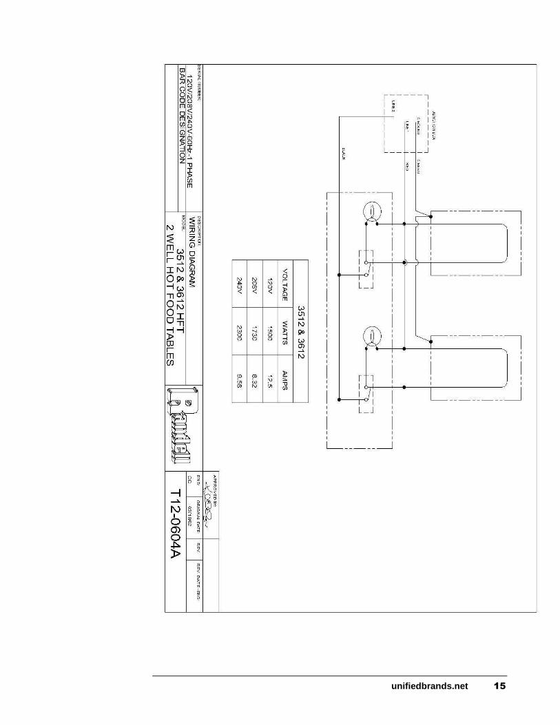
unifiedbrands.net 15

16 888-994-7636

unifiedbrands.net 17

18 888-994-7636

unifiedbrands.net 19
Trouble Shooting Guide
SYMPTOM POSSIBLE CAUSE PROCEDURE Unit doesn't heat 1. No power to unit 1. Plug in unit 2. Temperature control turned off 2. Check temperature control 3. Temperature control faulty 3. Test temperature control 4. Element does not heat 4. Test element for continuity
Unit too hot 1. Thermostat not shutting off 1. Test thermostat
Unit runs constantly 1. Too much water in well 1. 1” – 2” of water per well 2. Thermostat sensing bulb 2. Check location of sensing bulb
Unit leaking water 1. Drain 1. Check drains for leaks 2. Pan cracked 2. Call ASA for repair

20 888-994-7636
Replacement Parts Exploded
View
3300 Series Electric HFT

unifiedbrands.net 21
Replacement Parts Exploded
View
3500 Series Electric HFT

22 888-994-7636
Replacement Parts Exploded
View
3600 Series Electric HFT

unifiedbrands.net 23
Replacement Parts List
3000 Series Electric HFT
ITEM DESCRIPTION PART # 3 3 1 2
3 3 1 3
3 3 1 4
3 3 1 5
3 5 1 2
3 5 1 3
3 5 1 4
3 5 1 5
3 6 1 2
3 6 1 3
3 6 1 4
3 6 1 5
1A TOP, 2 WELL (30" X 33") RP TOP3312 X X X 1B TOP, 3 WELL (30" X 48") RP TOP3313 X X X 1C TOP, 4 WELL (30" X 63") RP TOP3314 X X X 1D TOP, 5 WELL (30" X 78") RP TOP3315 X X X 2A CUTTING BOARD, 7/16" POLY, 8 X 33 RP CPH0833 X X X 2B CUTTING BOARD, 7/16" POLY, 8 X 48 RP CPH0848 X X X 2C CUTTING BOARD, 7/16" POLY, 8 X 63 RP CPH0863 X X X 2D CUTTING BOARD, 7/16" POLY, 8 X 78 RP CPH0878 X X X 3 CLIP, 1/2" CUTTING BOARD RP CLP001 X X X X X X X X X X X X 4A PANEL, REAR 2 WELL (11.5" X 30.5") RP PNL0106 X X X 4B PANEL, REAR 3 WELL (11.5" X 45.5") RP PNL0107 X X X 4C PANEL, REAR 4 WELL (11.5" X 60.5") RP PNL0108 X X X 4D PANEL, REAR 5 WELL (11.5" X 76.5") RP PNL0109 X X X 5 SIDE, RIGHT RP SID0103 X X X X X X X X X X X X 6 SIDE, LEFT RP SID0104 X X X X X X X X X X X X 7 6" LEG HD LEG9902 X X X X X X X X X X X X 9 ELECTRIC HOT FOOD CONTROL EL HFT0201 X X X X X X X X X X X X 10 KNOB, CONTROL HD KNB0003 X X X X X X X X X X X X 11 LIGHT, INDICATOR EL LGT500 X X X X X X X X X X X X 12A SHELF, BOTTOM 2 WELL (29" X 32.5") RP SHL0103 X X X 12B SHELF, BOTTOM 2 WELL (29" X 47.5") RP SHL0104 X X X 12C SHELF, BOTTOM 2 WELL (29" X 62.5") RP SHL0105 X X X 12D SHELF, BOTTOM 2 WELL (29" X 62.5") RP SHL0106 X X X 13 CHANNEL, LEG RP CHN0101 X X X X X X X X X X X X 14-1A 120V PWR CORD W/ PLUG, 12/3, 5-20P EL WIR800 X X 14-1B 240V PWR CORD W/ PLUG, 14/3, 6-15P EL WIR0353 X X 14-C PWR CORD, 14/3, NO PLUG, 10' REQ'D EL WIR380 X X X 14-C1 20A ANGLE PLUG, 6-20P EL PLG620 X X X 14-D PWR CORD, 10/3, NO PLUG, 10' REQ'D EL WIR360 X X X X X 14-D1 30A/50A ANGLE PLUG, 6-30P/6-50P EL PLG0931 X X X X X 14-E PWR CORD, 12/3, NO PLUG, 10' REQ'D EL WIR370 X X 14-E1 30A/50A ANGLE PLUG, 6-30P/6-50P EL PLG0931 X X 14 F PWR CORD, 10/3, NO PLUG, 10' REQ'D EL WIR360 X X 14-F1 30A/50A ANGLE PLUG, 5-30P/5-50P EL PLG3125 X X 14-G PWR CORD, 8/3, NO PLUG, 10' REQ'D EL WIR350 X X X X X 14-G1 30A/50A ANGLE PLUG, 5-30P/5-50P EL PLG3125 X X X X X 14-H PWR CORD, 8/3, NO PLUG, 10' REQ'D EL WIR350 X X 14-H1 30A/50A ANGLE PLUG, 6-30P/6-50P EL PLG0931 X X 15 BOX, JUNCTION EL BOX042 X X X X X X X X X X X X 16 COVER, JUNCTION BOX EL CVR8465 X X X X X X X X X X X X

24 888-994-7636
ITEM DESCRIPTION PART # 3 3 1 2
3 3 1 3
3 3 1 4
3 3 1 5
3 5 1 2
3 5 1 3
3 5 1 4
3 5 1 5
3 6 1 2
3 6 1 3
3 6 1 4
3 6 1 5
17 STRAINER, DRAIN RP DSN001 X X X X X X X X 18 TANK (3600 SERIES) RP PAN0005 X X X X 19 TANK (3500 SERIES) RP TNK0103 X X X X 20A TANK 2 WELL (3312) 27" LONG RP TNK312 X 20B TANK 3 WELL (3313) 42" LONG RP TNK313 X 20C TANK 4 WELL (3314) 57" LONG RP TNK314 X 20D TANK 5 WELL (3315) 72" LONG RP TNK315 X 21A ELEMENT, 208V - 3300 SERIES RP ELM3245 X X X X 21B ELEMENT, 240V - 3300 SERIES RP ELM3247 X X X X 21C ELEMENT, 208V/240V-3500&3600 EL ELM1150 X X X X X X X X 21D ELEMENT, 120V/3500 & 3600/750watt EL ELM750 X X X X X X X X 21E ELEMENT, 208V/3500H & 3600H/1100watt EL ELM1172 X X X X X X X X 22 PAN, ASSY W/OUT ELEMENT 3300 RP PAN0105 X X X X 23 PAN, ASSY W/OUT ELEMENT 3600 RP PAN0104 X X X X X X X X 26A VALVE, 1" THD GATE (3300) PB VLV1000 X X X X 26B VALVE, 1/3" THR GATE (3600) PB VLV752 X X X X X X X 27 ELBOW, 90 DEGREE (1/2") SWEAT (3600) PB ELB504 X X X X X X X 28 TEE, 1/2" COPPER (3600) PB TEE502 X X X X X X X 29 ELBOW, (3/4 X 1/2) CAST (3600) PB ELB758 X X X X X X X 30 ADAPTER 1/2" FPT TO 1/2" SWEAT (3600) PB ADP120 X X X X X X X 31A PLATE SHELF, 2 WELL (3000 SERIES) RP SHL3512 X X X 31B PLATE SHELF, 3 WELL (3000 SERIES) RP SHL3513 X X X 31C PLATE SHELF, 4 WELL (3000 SERIES) RP SHL3514 X X X 31D PLATE SHELF, 5 WELL (3000 SERIES) RP SHL3515 X X X 32A CONTROL PANEL – 3312 B4 5.2014 RP CNT3312A X CONTROL PANEL – 3312 AFTER 5.2014 RP CNT3312B X
32B CONTROL PANEL – 3313 B4 5.2014 RP CNT3313A X CONTROL PANEL – 3313 AFTER 5.2014 RP CNT3313B X 32C CONTROL PANEL – 3314 B4 5.2014 RP CNT3314A X CONTROL PANEL – 3314 AFTER 5.2014 RP CNT3314B X 32D CONTROL PANEL – 3315 B4 5.2014 RP CNT3315A X CONTROL PANEL – 3315 AFTER 5.2014 RP CNT3315B X 33A CONTROL PANEL - 3512, 3612 B4 5.2014 RP CNT3512A X X
CONTROL PANEL-3512,3612 AFTER 5.2014 RP CNT3512B X X
33B CONTROL PANEL - 3513, 3613 B4 5.2014 RP CNT3513A X X
CONTROL PANEL-3513,3613 AFTER 5.2014 RP CNT3513B X X
33C CONTROL PANEL - 3514, 3614 B4 5.2014 RP CNT3514A X X
CONTROL PANEL-3514,3614 AFTER 5.2014 RP CNT3514B X X
33D CONTROL PANEL - 3515, 3615 B4 5.2014 RP CNT3515A X X
CONTROL PANEL-3515,3615 AFTER 5.2014 RP CNT3515B X X
NS 6" LOCKING CASTERS HD CST060 X X X X X X X X X X X X NS 6" NON LOCK CASTER HD CST061 X X X X X X X X X X X X NS 4" LOCKING CASTERS HD CST040HD X X X X X X X X X X X X NS 4" NON LOCK CASTERS HD CST041HD X X X X X X X X X X X X

unifiedbrands.net 25
NS FILL FAUCET HD FLR150 X X X X X X X X X X X X
NS SWITCH, RED ILLUMINATED ROCKER AFTER 5.2014 EL SWT610BE X X X X X X X X X X X X
NS NOT SHOWN

26 888-994-7636
NEMA Plug Configuration
3000 Series Electric HFT

unifiedbrands.net 27