Embed Size (px)
Citation preview

3000 METERING PUMPS3000 METERING PUMPS

3000 SERIES METERING PUMPS
LABORATORY ACCURACY INDUSTRIAL DURABILITY The Acromet 3000 Series incorporates a range of both diaphragm and plunger type metering pumps and glandless chemical transfer pumps. All models are positive displacement in action and are manufactured in a variety of materials to provide wide ranging chemical compatibility. Acromet 3000 metering pumps are precision pumps designed to be used where a high degree of metering accuracy must be maintained and where the utmost system reliability over extended periods is required. The 3000 maintains the Acromet tradition of robust construction and the concept of design simplicity – SIMPLY FOR RELIABILITY. RELIABILITY – derived from design features developed, perfected and proven over more than 25 years in a
wide variety of chemical processing and additive applications. SIMPLICITY – providing enhanced metering integrity, independent of complex components, lower service
requirements and simplified maintenance. QUALITY – manifest in the five year warranty of 3000 diaphragms.
WIDE APPLICATION VERSATILITY � Plunger or diaphragm liquid ends. � Capacity adjustment by pump stroke length and/or variable pump speed. � Remote, Manual, Pneumatic (20-100kPa), electric (4-20mA) control of stroke length adjustment and pump
speed. � Simplex, Multiplex and Multi-speed Multiplex. � Materials of construction to suit process. � Single or double valves on suction and discharge – flange or screw mounted. � Thirty different sizes and types of liquid end. � Six standard gear ratios – 46-180 strokes per minute (1450 rpm input speed). � Horizontal or Vertical motors. � Floor or Wall mounting.
ELECTRIC CONTROL � By electric actuator and electro servo controller.
Controller incorporates digital lineariser providing programmable linearization of pump output to input signal (4-20mA).

Acromet (Aust) Pty Ltd
14 Winterton Road, Clayton, Victoria 3168 Suite 302, 63-79 Parramatta Road, Silverwater, NSW 2128 Ph: (03) 9544 7333 • Fax: (03) 9543 6706 Ph: (02) 9647 2432 • Fax: (02) 9647 2599 Email: [email protected] www.acromet.com.au
CAPACITY / PRESSURE
DIAPHRAGM PUMPS LITRES PER HOUR
PLUNGER PUMPS LITRES PER HOUR
* Pressure ratings are for pumps in stainless steel construction. For higher pressures – consult Acromet. Capacities listed are nominal for simplex pumps at 100 kPa discharge pressure. Maximum pressure rating with plastic pump head 1400 kPa.
MODEL PUMP SPEED (STROKES / MINUTE) PRESSURE RATING
46 72 92 112 136 kPa
3000 R
001 1.3 2 2.6 3.2 3.8 2400
002 6.4 10 12.8 15.6 18.9 2400
005 12 19 24 30 36 2400
015 37 58 74 90 109 1750
025 66 103 132 161 195 1200
050 130 203 260 317 384 850
100 235 368 470 572 695 500
100H 340 532 680 828 350
150H 510 798 1020 1242 350
MODEL PUMP SPEED (STROKES / MINUTE) PRESSURE
RATING
46 72 92 112 MPs*
3000PR
001 0.3 0.45 0.6 0.73 14
002 1.2 1.88 2.4 2.92 14
003 2.6 4.2 5.2 6.3 14
005 4.7 7.4 9.4 11.4 8
007 10.6 16.6 21.2 26 5
010 19 29.7 38 46.3 3.5
012 29.5 46 59 72 2.4
015 42.5 66.5 85 103.5 2.4
017 57.8 90.5 115.6 140.7 1.4
020 75.5 118 151 184 1.4
3000PF
001 0.14 0.22 0.28 3.5
002 0.54 0.85 1.08 3.5
003 1.32 2.07 2.65 3.5
005 2.22 3.54 4.5 1.4
MODEL 3000 R
HEAVY DUTY
Manual Micrometer Adjustment
�
Multiplex �
Automatic Adjustment Electric or Pneumatic
�
Valves Double
Double Seal �
Diaphragm and Plunger Head
�
Diaphragm Actuation Hydraulic Mechanical

MP3000 Updated June 2012
Series 3000
Contents
1. SAFETY ............................................................................................................................. 1 1.1 General .............................................................................................................................. 1 1.2 Mechanical Precautions ......................................................................................................... 1 1.3 Electrical Precautions............................................................................................................ 1
2. INTRODUCTION................................................................................................................. 2
3. INSTALLATION .................................................................................................................. 2 3.1 Location ............................................................................................................................. 2
4. PIPING .............................................................................................................................. 2 4.1 General .............................................................................................................................. 2 4.2 Suction ............................................................................................................................... 3 4.3 Discharge ........................................................................................................................... 4 4.4 Piping Arrangement .............................................................................................................. 5
5. OPERATION....................................................................................................................... 6 5.1 Before Starting .................................................................................................................... 6 5.2 After Starting ...................................................................................................................... 6
6. CAPACITY ADJUSTMENT .................................................................................................... 7
7. MAINTENANCE ................................................................................................................... 8 7.1 Pre Maintenance Cleaning ..................................................................................................... 8 7.2 Lubrication .......................................................................................................................... 8 7.3 Suction & Discharge Valves ................................................................................................... 8 7.4 Diaphragm .......................................................................................................................... 9
8. TROUBLESHOOTING ........................................................................................................ 10
9. 3000 SERIES METERING PUMPS........................................................................................ 13 9.1 Drive End – Model 3000R Series - Section A-A ........................................................................ 13 9.2 Drive End – Model 3000R Series - Section A-A – Parts List........................................................ 14 9.3 Drive End – Model 3000R Series – Section A-A - Parts List cont. ................................................ 15 9.4 Drive End – Model 3000R Series – Section B-B ........................................................................ 16 9.5 Drive End – Model 3000R Series – Section B-B - Parts List........................................................ 16 9.6 Solution Head - Model 3001R – 001 ..................................................................................... 17 9.7 Solution End PVC - Model 3001R - 001 – Parts List .................................................................. 18 9.8 Solution End 316 SS - Model 3001R - 001 – Parts List .............................................................. 18 9.9 Solution End PVC - Model 3001R - 002 – Parts List .................................................................. 19 9.10 Solution End 316 SS - Model 3001R - 002 – Parts List .............................................................. 19 9.11 Solution End PVC - Model 3001R - 005 – Parts List .................................................................. 20 9.12 Solution End 316 SS - Model 3001R - 005 – Parts List .............................................................. 20 9.13 Solution End - Model 3001R – 015 ........................................................................................ 21 - Model 3001R – 025 ....................................................................................... 21 - Model 3001R – 050 ....................................................................................... 21 9.14 Solution End PVC - Model 3001R – 015 – Parts List ................................................................. 22 9.15 Solution End 316 SS - Model 3001R – 015 – Parts List ............................................................. 22 9.16 Solution End PVC - Model 3001R - 025 – Parts List .................................................................. 23 9.17 Solution End 316 SS - Model 3001R - 025 – Parts List .............................................................. 23 9.18 Solution End PVC - Model 3001R - 050 – Parts List .................................................................. 24 9.19 Solution End 316 SS - Model 3001R - 050 – Parts List .............................................................. 24 9.20 Solution End - Model 3001R - 100 ........................................................................................ 25 9.21 Solution End PVC - Model 3001R - 100 – Parts List .................................................................. 26 9.22 Solution End 316 SS - Model 3001R - 100 – Parts List .............................................................. 26 9.23 Drive End – Model 3000R Series- 100H - 150H - Section A-A ..................................................... 27 9.24 Drive End – Model 3000R Series – 100H Section A-A – Parts List .............................................. 28 9.25 Drive End – Model 3000R Series – 100H – 150H Section A-A - Parts List cont. ............................. 29 9.26 Drive End – Model 3000R Series - 100H – 150H – Section B-B ................................................... 30 9.27 Drive End – Model 3000R Series - 100H – 150H – Section B-B - Parts List ................................... 30 9.28 Solution End - Model 3001R – 100H ...................................................................................... 31 - Model 3001R – 150H ....................................................................................... 31 9.29 Solution End PVC - Model 3001R – 100H – Parts List ............................................................... 33 9.30 Solution End 316 SS - Model 3001R – 100H– Parts List ............................................................ 33 9.31 Solution End PVC - Model 3001R – 150H – Parts List ............................................................... 34 9.32 Solution End 316 SS - Model 3001R – 150H– Parts List ............................................................ 34
10. CALIBRATION OF A METERING PUMP ................................................................................ 35 CALIBRATION CYLINDER – INSTALLATION GUIDE ................................................................... 36
11. SERIES 500 VALVE INSTRUCTIONS ................................................................................... 37
APPENDIX ..................................................................................................................................... 40 1 EQUIPMENT DECONTAMINATION PROCEDURE DOC. No. QAPM-SD-19.0-1 ................................... 41 2 EQUIPMENT DECONTAMINATION ADVICE DOC. No. SD-19.0-1................................................... 42

MP3000 Updated June 2012
Page 1 Series 3000
METERING PUMPS 3000 SERIES
1. SAFETY
1.1 General
Please read and familiarise yourself with all sections of this and other equipment
manuals before proceeding with installation.
� Observe all standard precautions which apply to moving machinery.
� Observe all standard precautions which apply to electrical equipment,
drives and controls.
� Pay particular attention to special safety 'cautions' and 'notes' in this
manual.
1.2 Mechanical Precautions
� Prior to undertaking any mechanical maintenance repair, installation, etc.
SWITCH OFF, and disconnect the power before proceeding.
� Personnel must wear the appropriate protective safety attire and remove
loose clothing, jewellery etc.
1.3 Electrical Precautions
� Before undertaking work on the electrical controls or drives, disconnect
power and place a notice to advise others of the type of work in process.
� Ensure all necessary grounds are in place and solid.
� Do not disconnect or disable ground connections
CAUTION Follow all electrical regulations where required by electrical
engineering trades.
MP3000 Updated June 2012
Page 2 Series 3000
2. INTRODUCTION
Acromet metering pumps are designed and manufactured for long, low maintenance
service life and when properly applied, will give many years of consistent accurate
metering and trouble free operation.
The following instructions should be read and followed to correctly install and operate the
pump and ensure optimum pump life and performance.
Sectional arrangement drawings and Part Lists are enclosed at the end of this manual.
3. INSTALLATION
3.1 Location
3.1.1 It is desirable to locate the pump as close as possible to the supply
source (eg tank) in order to minimise friction losses in the suction line.
3.1.2 The location should preferably be dry and protected from rain and the
possibility of hosing down, with sufficient free space provided around the
pump to allow access for adjustment and maintenance.
3.1.3 The mounting surface should be even and level. The pump base
(mounting plate) is provided with two (2) holes for mounting bolts.
3.1.4 The motor spool can be arranged for wall mounting of some pumps if
desired – rearrangement in the field is not recommended.
4. PIPING
4.1 General
4.1.1 The pump suction valve is located at the bottom of the pump head and
the discharge valve on top. The pump cannot operate without these
valves and for correct operation, valves must be vertical.
4.1.2 Discharge pressure should be more than 20 kPa greater than suction
pressure to prevent over feeding or syphoning and to maintain metering
accuracy.
NOTE: When the difference is less than 20 kPa, a back pressure valve
and pulsation dampener should be installed in the discharge line.
The pulsation dampener should be located between pump and
valve, as close to the pump as possible.
MP3000 Updated June 2012
Page 3 Series 3000
4.1.3 A characteristic of reciprocating pump performance is pulsating flow.
Piping should be sized for flow rates at least 3.5 times greater than
maximum capacity of pumps.
NOTE: Small diameter piping will produce unpredictable flow rates and
system pressures.
4.1.4 Piping should be as short and straight as possible and arranged to avoid
loops or pockets where gas may accumulate.
4.1.5 All piping should be separately supported close to the pump to avoid
imposing pipe loads on the pump. When handling high or low
temperature liquids, measures should be taken to prevent distortion of
piping imposing loads on the pump.
4.1.6 All pipe work should be flushed clean of any solids which may be present
in the pipe work (i.e. weldslag, dirt following construction or repair)
before final connection to the pump and start-up.
4.1.7 Make provision in discharge piping where necessary to facilitate initial
priming of pumps against reduced pressure.
4.1.8 Capacity adjustment range for accuracy of metering, avoid over sizing of
metering pumps. Flow rates of less than 10% of pump maximum
capacity may produce unacceptable accuracy.
4.1.9 Where lengthy suction and discharge pipelines are involved or there is
limitation on size, install pulsation dampeners close to the pump to:
� Avoid cavitation – maintain metering accuracy.
� Reduce amplitude of pulsations
4.1.10 Ensure that the drain line from any pressure relief valve in the system
is:
� Suitably sized to ensure correct operation of the relief valve.
� Returns to the suction tank.
� Is fitted with a sight glass for visual indication.
4.2 Suction
4.2.1 Piping must be air tight.
4.2.2 For ease of maintenance an isolating valve should be located near the
pump inlet.
4.2.3 Solids should be prevented from entering low volume pumps or pumps
used for high accuracy metering. A strainer of 150-200 mesh is
recommended and should be adequately sized to prevent restriction of
flow.
MP3000 Updated June 2012
Page 4 Series 3000
4.2.4 Suction pipe entrance should be at least 75 mm above the bottom of
solution tank to allow settlement of larger solids in the tank.
4.2.5 Make provision in suction piping where necessary to facilitate automatic
venting of any gases likely to accumulate.
4.3 Discharge
4.3.1 Should it be necessary to install an isolating valve in the discharge line,
a relief valve must be installed between the pump and isolating valve.
4.3.2 The 3000 Metering Pump, being a positive displacement pump, will be
damaged if operated against a closed valve.
NOTE: The relief valve should be set to operate at the maximum rated pump
discharge pressure or maximum system operating pressure, whichever
is lower.
CAUTION: When pumping hazardous liquids the relief valve discharge
should be piped back to the supply source.
NOTE: Where relief valve is likely to operate frequently, to ensure correct
operation and maximise valve life, a pulsation dampener should be
installed between valve and pump
4.3.3 A pressure gauge with gauge protector should be installed to check if
the pump is not operating at too great a discharge pressure. The gauge
should be provided with a petcock valve for isolation from the system
when not required.
4.3.3 When pumping into a high pressure system, a non return valve should
be installed as a safety precaution at the injection point.
4.3.4 Make provision in pipe work to facilitate priming against reduced
pressure.

MP3000 Updated June 2012
Page 5 Series 3000
4.4 Piping Arrangement
Should it be necessary to install an isolating valve in
the discharge line, a relief valve must be installed in the line between the pump and isolating valve.
WRONG CORRECT
Metering pumps are positive displacement pumps and produce pulsating flow. Consequently there is considerable line pressure loss and suction piping should be sized to ensure adequate NPSHA. If piping extends for a considerable distance a suitable break tank or pulsation dampener should be installed near pump. the pump.
Avoid pockets or loops in piping where gas may accumulate.
WRONG CORRECT
Where the pump discharge line connects with a high pressure line, install a non return valve as a safety precaution.
The presence of solids in the pumped liquid can cause incorrect pump valve operation and affect metering accuracy. If solids are present install a strainer with 150 to 200 mesh and large mesh surface in order to keep pressure drop as small as possible and ensure that strainer does not become quickly clogged.
CORRECT
MP3000 Updated June 2012
Page 6 Series 3000
5. OPERATION
5.1 Before Starting
5.1.1 Ensure the pump will be operated within its specification.
5.1.2 Check gearbox oil level. Prior to leaving factory, each pump is filled to
the correct level with the recommended grade of oil (see maintenance
section).
5.1.3 Check direction of rotation. Correct direction is clockwise when viewing
pump from top of motor.
5.1.4 Ensure system control or isolating valves in discharge line are open.
5.2 After Starting
5.2.1 Pump will normally prime automatically. However, it may be necessary
to run the pump at maximum capacity to clear air. If this is
unsuccessful install a return line from discharge pipe to supply tank with
valve to facilitate priming at reduced pressure and/or air release.
CAUTION: If pumped liquid is hazardous do not disconnect discharge
pipe work.
5.2.2 Check that pump is operating correctly against discharge pressure.
5.2.3 Ensure that any problems are noted and appropriate corrective or
preventative action is taken.
MP3000 Updated June 2012
Page 7 Series 3000
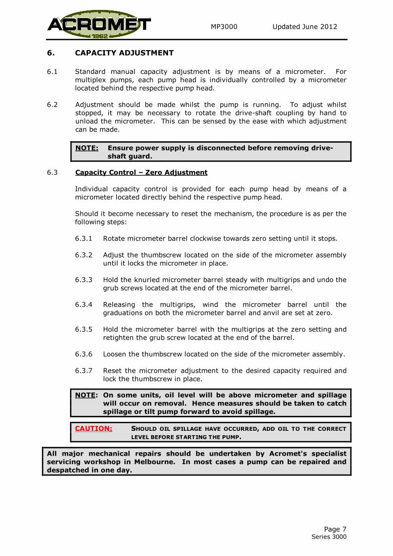
6. CAPACITY ADJUSTMENT
6.1 Standard manual capacity adjustment is by means of a micrometer. For
multiplex pumps, each pump head is individually controlled by a micrometer
located behind the respective pump head.
6.2 Adjustment should be made whilst the pump is running. To adjust whilst
stopped, it may be necessary to rotate the drive-shaft coupling by hand to
unload the micrometer. This can be sensed by the ease with which adjustment
can be made.
NOTE: Ensure power supply is disconnected before removing drive-
shaft guard.
6.3 Capacity Control – Zero Adjustment
Individual capacity control is provided for each pump head by means of a
micrometer located directly behind the respective pump head.
Should it become necessary to reset the mechanism, the procedure is as per the
following steps:
6.3.1 Rotate micrometer barrel clockwise towards zero setting until it stops.
6.3.2 Adjust the thumbscrew located on the side of the micrometer assembly
until it locks the micrometer in place.
6.3.3 Hold the knurled micrometer barrel steady with multigrips and undo the
grub screws located at the end of the micrometer barrel.
6.3.4 Releasing the multigrips, wind the micrometer barrel until the
graduations on both the micrometer barrel and anvil are set at zero.
6.3.5 Hold the micrometer barrel with the multigrips at the zero setting and
retighten the grub screw located at the end of the barrel.
6.3.6 Loosen the thumbscrew located on the side of the micrometer assembly.
6.3.7 Reset the micrometer adjustment to the desired capacity required and
lock the thumbscrew in place.
NOTE: On some units, oil level will be above micrometer and spillage
will occur on removal. Hence measures should be taken to catch
spillage or tilt pump forward to avoid spillage.
CAUTION: SHOULD OIL SPILLAGE HAVE OCCURRED, ADD OIL TO THE CORRECT
LEVEL BEFORE STARTING THE PUMP.
All major mechanical repairs should be undertaken by Acromet's specialist
servicing workshop in Melbourne. In most cases a pump can be repaired and
despatched in one day.

MP3000 Updated June 2012
Page 8 Series 3000
7. MAINTENANCE
7.1 Pre Maintenance Cleaning
� Flush the pump liquid head internals to remove all chemical residue.
� Clean the pumps exterior to ensure chemical free surface.
� Check that appropriate chemical handling and cleaning standards have
been met.
CAUTION: ACROMET (AUST) PTY LTD IS UNABLE TO ACCEPT ANY METERING PUMP
RETURNED FOR MAINTENANCE THAT HAS NOT BEEN SUITABLY CLEANED.
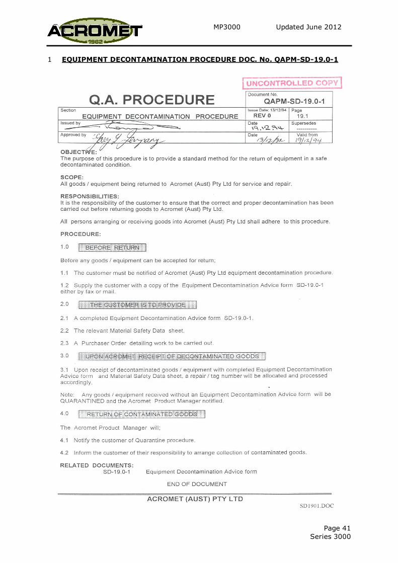
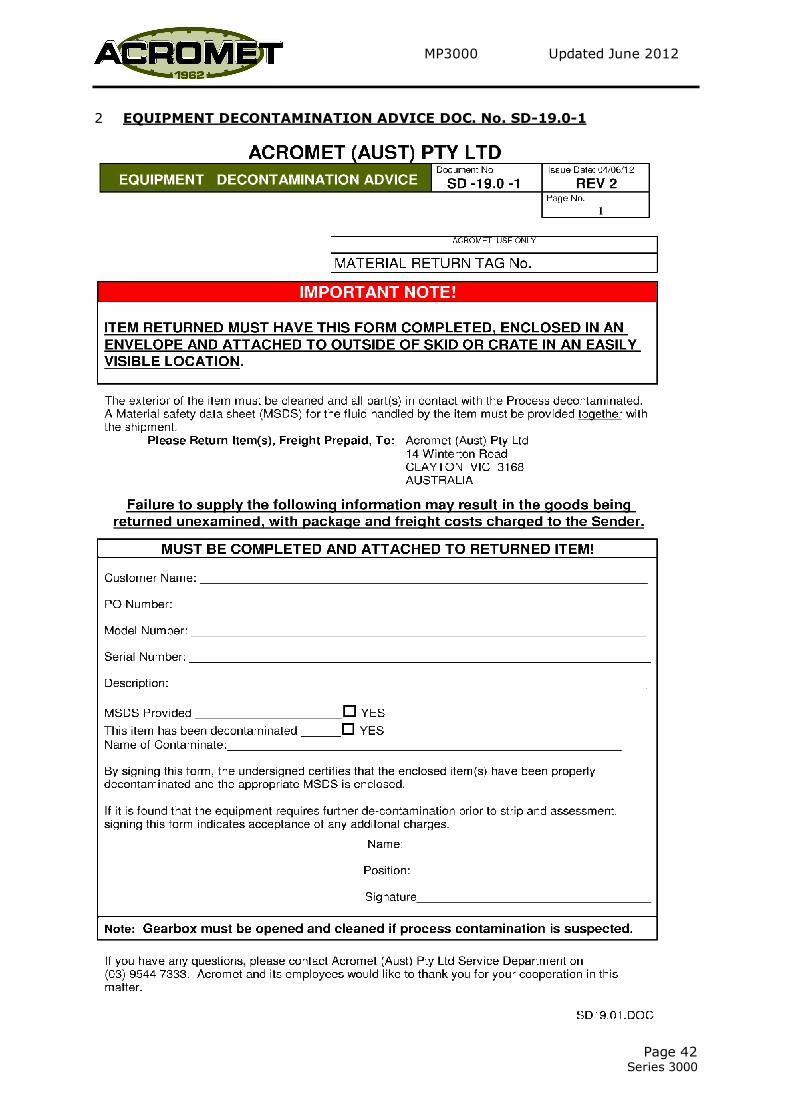
It is an Acromet Quality Assurance policy that all equipment returned for repair or
service be supplied with a completed copy of the 'Equipment Decontamination Advice'
form, as shown on page 42 of this manual.
7.2 Lubrication
7.2.1 Change oil after the first month of operation and at 6 months intervals
thereafter.
The following are recommended grades:
SHELL : OMALA 320
BP : GR-XP-320 ISO
MOBIL : MOBIL GEAR 632
CASTROL : ALPHA SP 320
7.2.2 Correct oil level is the horizontal centre line of the solution head.
7.3 Suction & Discharge Valves
7.3.1 During routine maintenance, valves should be dismantled and checked.
Replace worn ball checks and valve seats. When pumping clean liquids
of moderate viscosity, valves will give many years of trouble free
service. However, valve life can be reduced in applications where
discharge pressure is high, liquid viscosity low or solids are present.
NOTE: Should it be necessary to service the valves, cleanliness is essential and
care should be taken to avoid damaging components.
Refer to valve drawing at end of manual prior to dismantling.
7.3.2 When reassembling, ensure that all O-Rings, ball checks and ball stops
are in the correct position. Failure to fit ball stops can result in closed
head situation and severe pump damage.

MP3000 Updated June 2012
Page 9 Series 3000
7.4 Diaphragm
7.4.1 When fitting a new diaphragm, the diaphragm bolt should be tightened
firmly with the correct spanner available from Acromet.
7.4.2 Before tightening the diaphragm bolt, capacity adjustment should be set
at 0% for the 3000R and 3000F models. For the 3000T model, stroke
length should be in the extreme forward position (toward solution
head).
7.4.3 Place diaphragm in position ensuring holes line up and screw in two (2)
solution head bolts (opposing each other) through diaphragm bolt holes
into solution head adaptor. This is to ensure that the diaphragm does
not rotate when tightening the diaphragm bolt.
NOTE: Excessive tightening of solution head bolts should be avoided as
this will result in early diaphragm failure.
7.4.4 After the new diaphragm has been fitted, calibration should be checked
and monitored until diaphragm has stabilised.
MP3000 Updated June 2012
Page 10 Series 3000
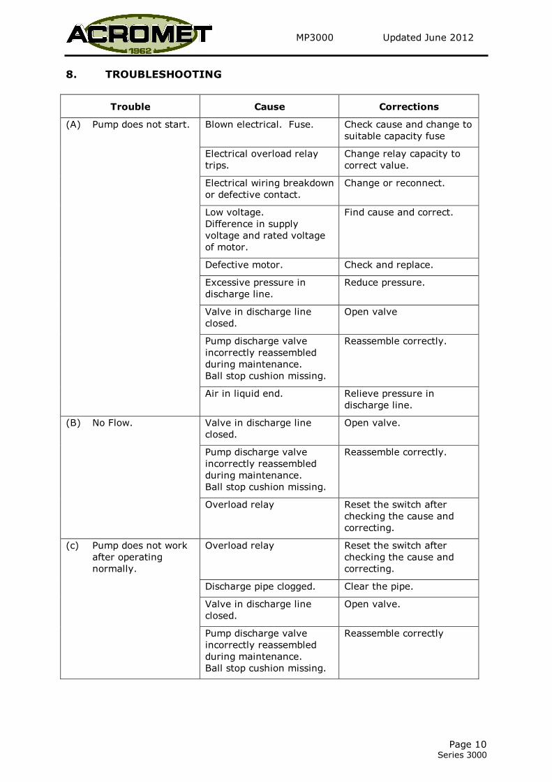
8. TROUBLESHOOTING
Trouble Cause Corrections
(A) Pump does not start. Blown electrical. Fuse. Check cause and change to
suitable capacity fuse
Electrical overload relay
trips.
Change relay capacity to
correct value.
Electrical wiring breakdown
or defective contact.
Change or reconnect.
Low voltage.
Difference in supply
voltage and rated voltage
of motor.
Find cause and correct.
Defective motor. Check and replace.
Excessive pressure in
discharge line.
Reduce pressure.
Valve in discharge line
closed.
Open valve
Pump discharge valve
incorrectly reassembled
during maintenance.
Ball stop cushion missing.
Reassemble correctly.
Air in liquid end. Relieve pressure in
discharge line.
(B) No Flow. Valve in discharge line
closed.
Open valve.
Pump discharge valve
incorrectly reassembled
during maintenance.
Ball stop cushion missing.
Reassemble correctly.
Overload relay Reset the switch after
checking the cause and
correcting.
(c) Pump does not work
after operating
normally.
Overload relay Reset the switch after
checking the cause and
correcting.
Discharge pipe clogged. Clear the pipe.
Valve in discharge line
closed.
Open valve.
Pump discharge valve
incorrectly reassembled
during maintenance.
Ball stop cushion missing.
Reassemble correctly
MP3000 Updated June 2012
Page 11 Series 3000
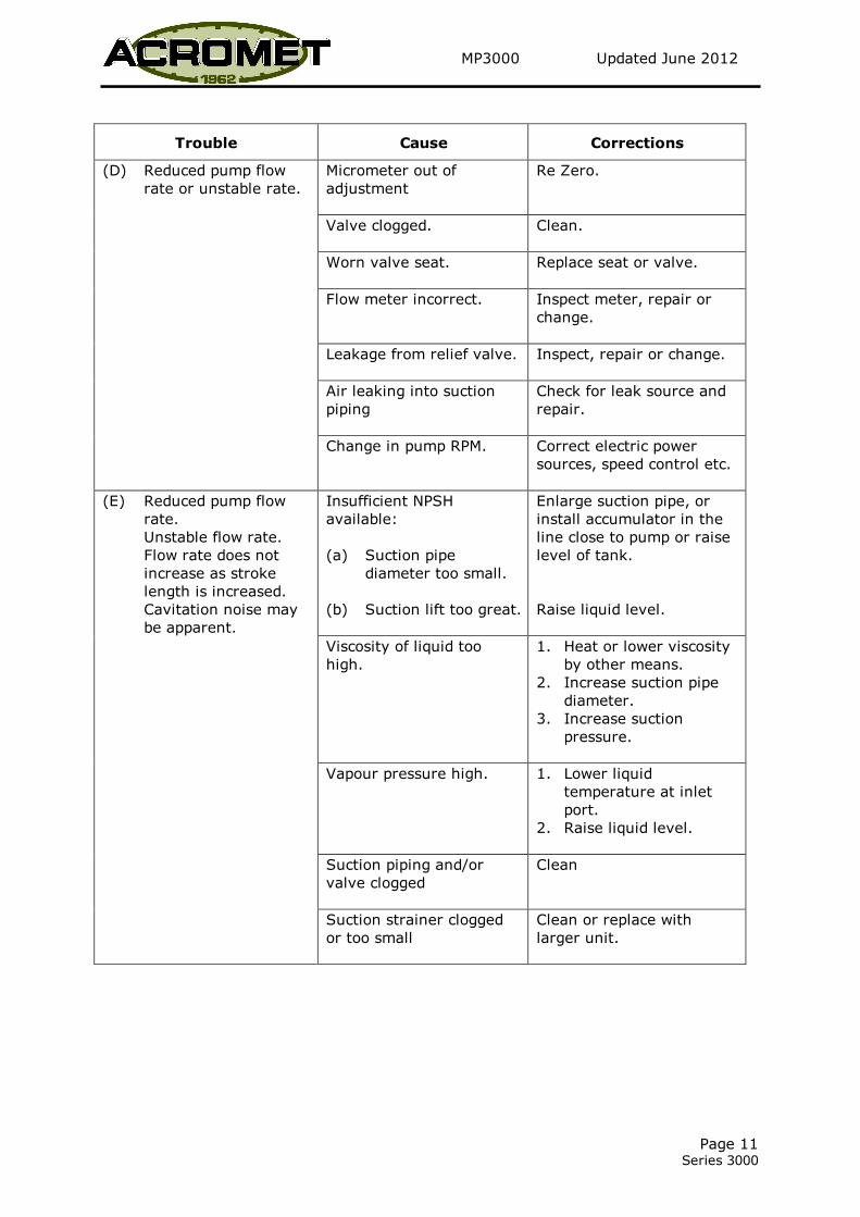
Trouble Cause Corrections
(D) Reduced pump flow
rate or unstable rate.
Micrometer out of
adjustment
Re Zero.
Valve clogged. Clean.
Worn valve seat. Replace seat or valve.
Flow meter incorrect. Inspect meter, repair or
change.
Leakage from relief valve. Inspect, repair or change.
Air leaking into suction
piping
Check for leak source and
repair.
Change in pump RPM. Correct electric power
sources, speed control etc.
(E) Reduced pump flow
rate.
Unstable flow rate.
Flow rate does not
increase as stroke
length is increased.
Cavitation noise may
be apparent.
Insufficient NPSH
available:
(a) Suction pipe
diameter too small.
(b) Suction lift too great.
Enlarge suction pipe, or
install accumulator in the
line close to pump or raise
level of tank.
Raise liquid level.
Viscosity of liquid too
high.
1. Heat or lower viscosity
by other means.
2. Increase suction pipe
diameter.
3. Increase suction
pressure.
Vapour pressure high. 1. Lower liquid
temperature at inlet
port.
2. Raise liquid level.
Suction piping and/or
valve clogged
Clean
Suction strainer clogged
or too small
Clean or replace with
larger unit.

MP3000 Updated June 2012
Page 12 Series 3000
Trouble Cause Correction
(F) Excessive pump flow
rate.
Flow continues after
pump has stopped.
Pressure difference across
pump less than 20 KPa
Increase pressure
difference (ie install back
pressure valve).
Discharge line too long or
diameter too small
Reduce length and/or
increase diameter.
Install accumulator in
discharge line.
(G) Liquid leakage from
pump adaptor drain.
Ruptured diaphragm. Check/replace diaphragm.
(H) Knocking sound in
gearbox.
Excessive discharge
pressure
Check discharge pressure.
(I) Liquid end noise. Rhythmic noise of pump
valves
Normal
Clogged discharge or
suction valve
Clean
(J) Overheating of motor. Improper voltage Adjust voltage to motor
specification.
Overload (Refer to Section K).
Inadequate ventilation Change motor or relocate
(K) Overload. Improper Oil Change
Discharge pressure too
high
Lower to permissible
pressure
Erratic noise of pump
valves
1. Clean valves.
2. Increase pressure
difference (ie install
back pressure valve).
MP3000 Updated June 2012
Page 13 Series 3000
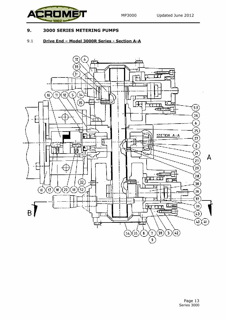
9. 3000 SERIES METERING PUMPS
9.1 Drive End – Model 3000R Series - Section A-A
MP3000 Updated June 2012
Page 14 Series 3000
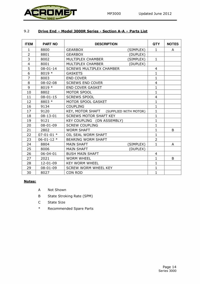
9.2 Drive End – Model 3000R Series - Section A-A – Parts List
ITEM PART NO DESCRIPTION QTY NOTES
1 8800 GEARBOX (SIMPLEX) 1 A
2 8801 GEARBOX (DUPLEX)
3 8002 MULTIPLEX CHAMBER (SIMPLEX) 1
4 8001 MULTIPLEX CHAMBER (DUPLEX)
5 08-01-14 SCREWS MULTIPLEX CHAMBER 4
6 8019 * GASKETS 1
7 8003 END COVER 1
8 08-02-08 SCREWS END COVER 4
9 8019 * END COVER GASKET 1
10 8802 MOTOR SPOOL 1
11 08-01-15 SCREWS SPOOL 4
12 8803 * MOTOR SPOOL GASKET 1
16 9134 COUPLING 1
17 9120 KEY, MOTOR SHAFT (SUPPLIED WITH MOTOR) 1
18 08-13-01 SCREWS MOTOR SHAFT KEY 1
19 9121 KEY COUPLING (ON ASSEMBLY) 1
20 08-01-09 SCREW COUPLING 1
21 2802 WORM SHAFT 1 B
22 07-01-01 * OIL SEAL WORM SHAFT 1
23 06-01-12 * BEARING WORM SHAFT 2
24 8804 MAIN SHAFT (SIMPLEX) 1 A
25 8006 MAIN SHAFT (DUPLEX)
26 06-04-01 BUSH MAIN SHAFT 4
27 2021 WORM WHEEL 1 B
28 12-01-09 KEY WORM WHEEL 1
29 08-01-09 SCREW WORM WHEEL KEY 1
30 8027 CON ROD 1
Notes:
A Not Shown
B State Stroking Rate (SPM)
C State Size
* Recommended Spare Parts

MP3000 Updated June 2012
Page 15 Series 3000
9.3 Drive End – Model 3000R Series – Section A-A - Parts List cont.
ITEM PART NO DESCRIPTION QTY NOTES
31 2521 BUSH CON ROD 1
32 8016 ECCENTRIC 1 C
33 06-05-01 LINER ECCENTRIC 1
34 12-01-09 KEY ECCENTRIC 1
35 08-13-01 SCREWS ECCENTRIC KEY 1
36 8025 PISTON PRIMARY 1
37 8026 CROSS HEAD 1
38 8024 PIN WRIST 1
39 8829 SPRING RETURN 1 C
40 8028 SLEEVE, PISTON 1
41 8831 GASKET, PISTON SLEEVE 1
42 08-01-17 SCREW PISTON SLEEVE 2
43 07-01-02 * SEAL PRIMARY PISTON 1
51 08-12-01 PLUG, DRAIN 2 A
52 08-12-02 PLUG 1
54 9111 PLATE, NAME 1
55 08-10-01 SCREW NAME PLATE 4
56 06-04-02 WRIST PIN BUSH 1
57 09-02-03 SPRING WASHER, MOTOR 4 A
58 08-08-10 THUMB SCREW, BARREL LOCK 1 A
59 8824 SEAL RING, PISTON SLEEVE 1
60 08-01-23 SCREW, ADAPTOR 4 A
Notes:
A Not Shown
B State Stroking Rate (SPM)
C State Size
* Recommended Spare Parts
MP3000 Updated June 2012
Page 16 Series 3000
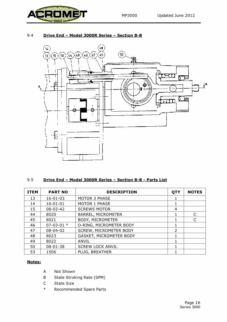
9.4 Drive End – Model 3000R Series – Section B-B
9.5 Drive End – Model 3000R Series – Section B-B - Parts List
ITEM PART NO DESCRIPTION QTY NOTES
13 16-01-03 MOTOR 3 PHASE 1
14 16-01-01 MOTOR 1 PHASE 1
15 08-02-42 SCREWS MOTOR 4
44 8020 BARREL, MICROMETER 1 C
45 8021 BODY, MICROMETER 1 C
46 07-03-01 * O-RING, MICROMETER BODY 1
47 08-04-02 SCREW, MICROMETER BODY 2
48 8023 GASKET, MICROMETER BODY 1
49 8022 ANVIL 1
50 08-01-38 SCREW LOCK ANVIL 1
53 1506 PLUG, BREATHER 1
Notes:
A Not Shown
B State Stroking Rate (SPM)
C State Size
* Recommended Spare Parts

MP3000 Updated June 2012
Page 17 Series 3000
9.6 Solution Head - Model 3001R – 001
Model 3001R – 002
Model 3001R – 005
MP3000 Updated June 2012
Page 18 Series 3000
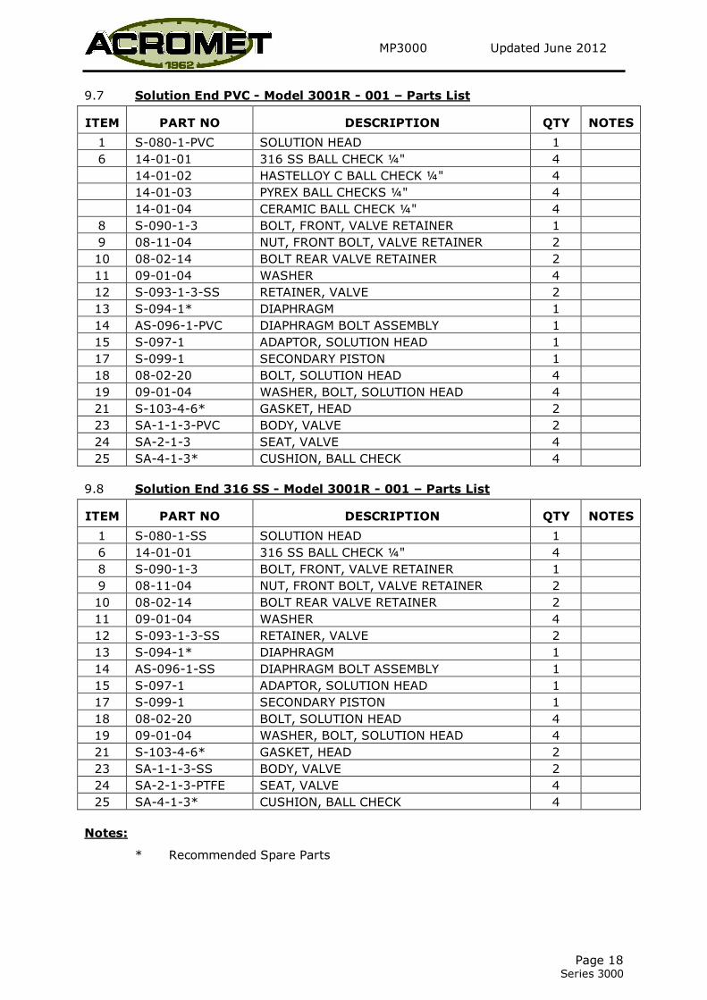
9.7 Solution End PVC - Model 3001R - 001 – Parts List
ITEM PART NO DESCRIPTION QTY NOTES
1 S-080-1-PVC SOLUTION HEAD 1
6 14-01-01 316 SS BALL CHECK ¼" 4
14-01-02 HASTELLOY C BALL CHECK ¼" 4
14-01-03 PYREX BALL CHECKS ¼" 4
14-01-04 CERAMIC BALL CHECK ¼" 4
8 S-090-1-3 BOLT, FRONT, VALVE RETAINER 1
9 08-11-04 NUT, FRONT BOLT, VALVE RETAINER 2
10 08-02-14 BOLT REAR VALVE RETAINER 2
11 09-01-04 WASHER 4
12 S-093-1-3-SS RETAINER, VALVE 2
13 S-094-1* DIAPHRAGM 1
14 AS-096-1-PVC DIAPHRAGM BOLT ASSEMBLY 1
15 S-097-1 ADAPTOR, SOLUTION HEAD 1
17 S-099-1 SECONDARY PISTON 1
18 08-02-20 BOLT, SOLUTION HEAD 4
19 09-01-04 WASHER, BOLT, SOLUTION HEAD 4
21 S-103-4-6* GASKET, HEAD 2
23 SA-1-1-3-PVC BODY, VALVE 2
24 SA-2-1-3 SEAT, VALVE 4
25 SA-4-1-3* CUSHION, BALL CHECK 4
9.8 Solution End 316 SS - Model 3001R - 001 – Parts List
ITEM PART NO DESCRIPTION QTY NOTES
1 S-080-1-SS SOLUTION HEAD 1
6 14-01-01 316 SS BALL CHECK ¼" 4
8 S-090-1-3 BOLT, FRONT, VALVE RETAINER 1
9 08-11-04 NUT, FRONT BOLT, VALVE RETAINER 2
10 08-02-14 BOLT REAR VALVE RETAINER 2
11 09-01-04 WASHER 4
12 S-093-1-3-SS RETAINER, VALVE 2
13 S-094-1* DIAPHRAGM 1
14 AS-096-1-SS DIAPHRAGM BOLT ASSEMBLY 1
15 S-097-1 ADAPTOR, SOLUTION HEAD 1
17 S-099-1 SECONDARY PISTON 1
18 08-02-20 BOLT, SOLUTION HEAD 4
19 09-01-04 WASHER, BOLT, SOLUTION HEAD 4
21 S-103-4-6* GASKET, HEAD 2
23 SA-1-1-3-SS BODY, VALVE 2
24 SA-2-1-3-PTFE SEAT, VALVE 4
25 SA-4-1-3* CUSHION, BALL CHECK 4
Notes:
* Recommended Spare Parts
MP3000 Updated June 2012
Page 19 Series 3000
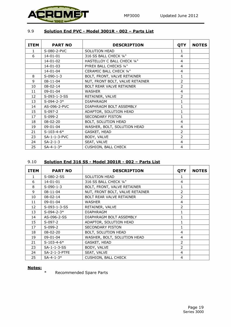
9.9 Solution End PVC - Model 3001R - 002 – Parts List
ITEM PART NO DESCRIPTION QTY NOTES
1 S-080-2-PVC SOLUTION HEAD 1
6 14-01-01 316 SS BALL CHECK ¼" 4
14-01-02 HASTELLOY C BALL CHECK ¼" 4
14-01-03 PYREX BALL CHECKS ¼" 4
14-01-04 CERAMIC BALL CHECK ¼" 4
8 S-090-1-3 BOLT, FRONT, VALVE RETAINER 1
9 08-11-04 NUT, FRONT BOLT, VALVE RETAINER 2
10 08-02-14 BOLT REAR VALVE RETAINER 2
11 09-01-04 WASHER 4
12 S-093-1-3-SS RETAINER, VALVE 2
13 S-094-2-3* DIAPHRAGM 1
14 AS-096-2-PVC DIAPHRAGM BOLT ASSEMBLY 1
15 S-097-2 ADAPTOR, SOLUTION HEAD 1
17 S-099-2 SECONDARY PISTON 1
18 08-02-20 BOLT, SOLUTION HEAD 4
19 09-01-04 WASHER, BOLT, SOLUTION HEAD 4
21 S-103-4-6* GASKET, HEAD 2
23 SA-1-1-3-PVC BODY, VALVE 2
24 SA-2-1-3 SEAT, VALVE 4
25 SA-4-1-3* CUSHION, BALL CHECK 4
9.10 Solution End 316 SS - Model 3001R - 002 – Parts List
ITEM PART NO DESCRIPTION QTY NOTES
1 S-080-2-SS SOLUTION HEAD 1
6 14-01-01 316 SS BALL CHECK ¼" 4
8 S-090-1-3 BOLT, FRONT, VALVE RETAINER 1
9 08-11-04 NUT, FRONT BOLT, VALVE RETAINER 2
10 08-02-14 BOLT REAR VALVE RETAINER 2
11 09-01-04 WASHER 4
12 S-093-1-3-SS RETAINER, VALVE 2
13 S-094-2-3* DIAPHRAGM 1
14 AS-096-2-SS DIAPHRAGM BOLT ASSEMBLY 1
15 S-097-2 ADAPTOR, SOLUTION HEAD 1
17 S-099-2 SECONDARY PISTON 1
18 08-02-20 BOLT, SOLUTION HEAD 4
19 09-01-04 WASHER, BOLT, SOLUTION HEAD 4
21 S-103-4-6* GASKET, HEAD 2
23 SA-1-1-3-SS BODY, VALVE 2
24 SA-2-1-3-PTFE SEAT, VALVE 4
25 SA-4-1-3* CUSHION, BALL CHECK 4
Notes:
* Recommended Spare Parts
MP3000 Updated June 2012
Page 20 Series 3000
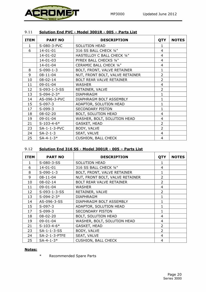
9.11 Solution End PVC - Model 3001R - 005 – Parts List
ITEM PART NO DESCRIPTION QTY NOTES
1 S-080-3-PVC SOLUTION HEAD 1
6 14-01-01 316 SS BALL CHECK ¼" 4
14-01-02 HASTELLOY C BALL CHECK ¼" 4
14-01-03 PYREX BALL CHECKS ¼" 4
14-01-04 CERAMIC BALL CHECK ¼" 4
8 S-090-1-3 BOLT, FRONT, VALVE RETAINER 1
9 08-11-04 NUT, FRONT BOLT, VALVE RETAINER 2
10 08-02-14 BOLT REAR VALVE RETAINER 2
11 09-01-04 WASHER 4
12 S-093-1-3-SS RETAINER, VALVE 2
13 S-094-2-3* DIAPHRAGM 1
14 AS-096-3-PVC DIAPHRAGM BOLT ASSEMBLY 1
15 S-097-3 ADAPTOR, SOLUTION HEAD 1
17 S-099-3 SECONDARY PISTON 1
18 08-02-20 BOLT, SOLUTION HEAD 4
19 09-01-04 WASHER, BOLT, SOLUTION HEAD 4
21 S-103-4-6* GASKET, HEAD 2
23 SA-1-1-3-PVC BODY, VALVE 2
24 SA-2-1-3 SEAT, VALVE 4
25 SA-4-1-3* CUSHION, BALL CHECK 4
9.12 Solution End 316 SS - Model 3001R - 005 – Parts List
ITEM PART NO DESCRIPTION QTY NOTES
1 S-080-3-SS SOLUTION HEAD 1
6 14-01-01 316 SS BALL CHECK ¼" 4
8 S-090-1-3 BOLT, FRONT, VALVE RETAINER 1
9 08-11-04 NUT, FRONT BOLT, VALVE RETAINER 2
10 08-02-14 BOLT REAR VALVE RETAINER 2
11 09-01-04 WASHER 4
12 S-093-1-3-SS RETAINER, VALVE 2
13 S-094-2-3* DIAPHRAGM 1
14 AS-096-3-SS DIAPHRAGM BOLT ASSEMBLY 1
15 S-097-3 ADAPTOR, SOLUTION HEAD 1
17 S-099-3 SECONDARY PISTON 1
18 08-02-20 BOLT, SOLUTION HEAD 4
19 09-01-04 WASHER, BOLT, SOLUTION HEAD 4
21 S-103-4-6* GASKET, HEAD 2
23 SA-1-1-3-SS BODY, VALVE 2
24 SA-2-1-3-PTFE SEAT, VALVE 4
25 SA-4-1-3* CUSHION, BALL CHECK 4
Notes:
* Recommended Spare Parts

MP3000 Updated June 2012
Page 21 Series 3000
9.13 Solution End - Model 3001R – 015
- Model 3001R – 025
- Model 3001R – 050
MP3000 Updated June 2012
Page 22 Series 3000
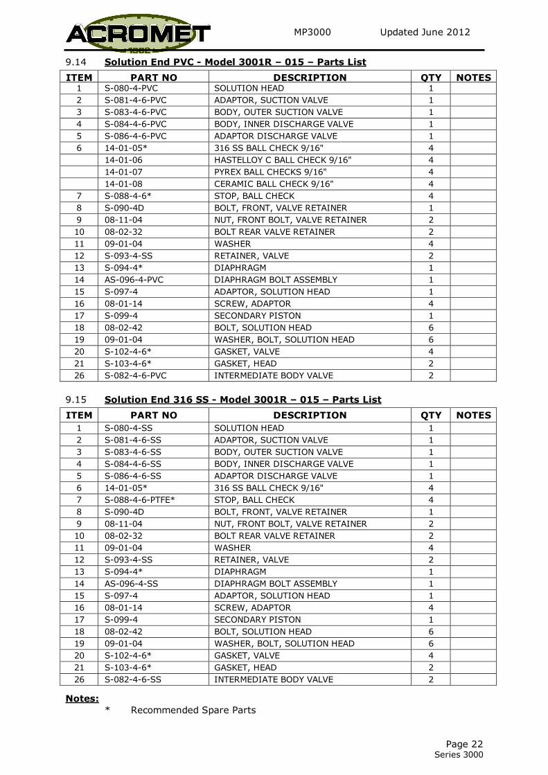
9.14 Solution End PVC - Model 3001R – 015 – Parts List
ITEM PART NO DESCRIPTION QTY NOTES 1 S-080-4-PVC SOLUTION HEAD 1
2 S-081-4-6-PVC ADAPTOR, SUCTION VALVE 1
3 S-083-4-6-PVC BODY, OUTER SUCTION VALVE 1
4 S-084-4-6-PVC BODY, INNER DISCHARGE VALVE 1
5 S-086-4-6-PVC ADAPTOR DISCHARGE VALVE 1
6 14-01-05* 316 SS BALL CHECK 9/16" 4
14-01-06 HASTELLOY C BALL CHECK 9/16" 4
14-01-07 PYREX BALL CHECKS 9/16" 4
14-01-08 CERAMIC BALL CHECK 9/16" 4
7 S-088-4-6* STOP, BALL CHECK 4
8 S-090-4D BOLT, FRONT, VALVE RETAINER 1
9 08-11-04 NUT, FRONT BOLT, VALVE RETAINER 2
10 08-02-32 BOLT REAR VALVE RETAINER 2
11 09-01-04 WASHER 4
12 S-093-4-SS RETAINER, VALVE 2
13 S-094-4* DIAPHRAGM 1
14 AS-096-4-PVC DIAPHRAGM BOLT ASSEMBLY 1
15 S-097-4 ADAPTOR, SOLUTION HEAD 1
16 08-01-14 SCREW, ADAPTOR 4
17 S-099-4 SECONDARY PISTON 1
18 08-02-42 BOLT, SOLUTION HEAD 6
19 09-01-04 WASHER, BOLT, SOLUTION HEAD 6
20 S-102-4-6* GASKET, VALVE 4
21 S-103-4-6* GASKET, HEAD 2
26 S-082-4-6-PVC INTERMEDIATE BODY VALVE 2
9.15 Solution End 316 SS - Model 3001R – 015 – Parts List
ITEM PART NO DESCRIPTION QTY NOTES
1 S-080-4-SS SOLUTION HEAD 1
2 S-081-4-6-SS ADAPTOR, SUCTION VALVE 1
3 S-083-4-6-SS BODY, OUTER SUCTION VALVE 1
4 S-084-4-6-SS BODY, INNER DISCHARGE VALVE 1
5 S-086-4-6-SS ADAPTOR DISCHARGE VALVE 1
6 14-01-05* 316 SS BALL CHECK 9/16" 4
7 S-088-4-6-PTFE* STOP, BALL CHECK 4
8 S-090-4D BOLT, FRONT, VALVE RETAINER 1
9 08-11-04 NUT, FRONT BOLT, VALVE RETAINER 2
10 08-02-32 BOLT REAR VALVE RETAINER 2
11 09-01-04 WASHER 4
12 S-093-4-SS RETAINER, VALVE 2
13 S-094-4* DIAPHRAGM 1
14 AS-096-4-SS DIAPHRAGM BOLT ASSEMBLY 1
15 S-097-4 ADAPTOR, SOLUTION HEAD 1
16 08-01-14 SCREW, ADAPTOR 4
17 S-099-4 SECONDARY PISTON 1
18 08-02-42 BOLT, SOLUTION HEAD 6
19 09-01-04 WASHER, BOLT, SOLUTION HEAD 6
20 S-102-4-6* GASKET, VALVE 4
21 S-103-4-6* GASKET, HEAD 2
26 S-082-4-6-SS INTERMEDIATE BODY VALVE 2
Notes:
* Recommended Spare Parts
MP3000 Updated June 2012
Page 23 Series 3000
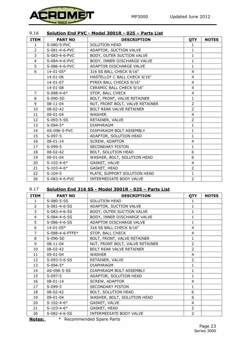
9.16 Solution End PVC - Model 3001R - 025 – Parts List
ITEM PART NO DESCRIPTION QTY NOTES
1 S-080-5-PVC SOLUTION HEAD 1
2 S-081-4-6-PVC ADAPTOR, SUCTION VALVE 1
3 S-083-4-6-PVC BODY, OUTER SUCTION VALVE 1
4 S-084-4-6-PVC BODY, INNER DISCHARGE VALVE 1
5 S-086-4-6-PVC ADAPTOR DISCHARGE VALVE 1
6 14-01-05* 316 SS BALL CHECK 9/16" 4
14-01-06 HASTELLOY C BALL CHECK 9/16" 4
14-01-07 PYREX BALL CHECKS 9/16" 4
14-01-08 CERAMIC BALL CHECK 9/16" 4
7 S-088-4-6* STOP, BALL CHECK 4
8 S-090-5D BOLT, FRONT, VALVE RETAINER 1
9 08-11-04 NUT, FRONT BOLT, VALVE RETAINER 2
10 08-02-42 BOLT REAR VALVE RETAINER 2
11 09-01-04 WASHER 4
12 S-093-5-SS RETAINER, VALVE 2
13 S-094-5* DIAPHRAGM 1
14 AS-096-5-PVC DIAPHRAGM BOLT ASSEMBLY 1
15 S-097-5 ADAPTOR, SOLUTION HEAD 1
16 08-01-14 SCREW, ADAPTOR 4
17 S-099-5 SECONDARY PISTON 1
18 08-02-42 BOLT, SOLUTION HEAD 6
19 09-01-04 WASHER, BOLT, SOLUTION HEAD 6
20 S-102-4-6* GASKET, VALVE 4
21 S-103-4-6* GASKET, HEAD 2
22 S-104-5 PLATE, SUPPORT SOLUTION HEAD 1
26 S-082-4-6-PVC INTERMEDIATE BODY VALVE 2
9.17 Solution End 316 SS - Model 3001R - 025 – Parts List
ITEM PART NO DESCRIPTION QTY NOTES
1 S-080-5-SS SOLUTION HEAD 1
2 S-081-4-6-SS ADAPTOR, SUCTION VALVE 1
3 S-083-4-6-SS BODY, OUTER SUCTION VALVE 1
4 S-084-4-6-SS BODY, INNER DISCHARGE VALVE 1
5 S-086-4-6-SS ADAPTOR DISCHARGE VALVE 1
6 14-01-05* 316 SS BALL CHECK 9/16" 4
7 S-088-4-6-PTFE* STOP, BALL CHECK 4
8 S-090-5D BOLT, FRONT, VALVE RETAINER 1
9 08-11-04 NUT, FRONT BOLT, VALVE RETAINER 2
10 08-02-42 BOLT REAR VALVE RETAINER 2
11 09-01-04 WASHER 4
12 S-093-5-6-SS RETAINER, VALVE 2
13 S-094-5* DIAPHRAGM 1
14 AS-096-5-SS DIAPHRAGM BOLT ASSEMBLY 1
15 S-097-5 ADAPTOR, SOLUTION HEAD 1
16 08-01-14 SCREW, ADAPTOR 4
17 S-099-5 SECONDARY PISTON 1
18 08-02-42 BOLT, SOLUTION HEAD 6
19 09-01-04 WASHER, BOLT, SOLUTION HEAD 6
20 S-102-4-6* GASKET, VALVE 4
21 S-103-4-6* GASKET, HEAD 2
26 S-082-4-6-SS INTERMEDIATE BODY VALVE 2
Notes: * Recommended Spare Parts

MP3000 Updated June 2012
Page 24 Series 3000
9.18 Solution End PVC - Model 3001R - 050 – Parts List
ITEM PART NO DESCRIPTION QTY NOTES
1 S-080-6-PVC SOLUTION HEAD 1
2 S-081-4-6-PVC ADAPTOR, SUCTION VALVE 1
3 S-083-4-6-PVC BODY, OUTER SUCTION VALVE 1
4 S-084-4-6-PVC BODY, INNER DISCHARGE VALVE 1
5 S-086-4-6-PVC ADAPTOR DISCHARGE VALVE 1
6 14-01-05* 316 SS BALL CHECK 9/16" 4
14-01-06 HASTELLOY C BALL CHECK 9/16" 4
14-01-07 PYREX BALL CHECKS 9/16" 4
14-01-08 CERAMIC BALL CHECK 9/16" 4
7 S-088-4-6-PVC* STOP, BALL CHECK 4
8 S-090-6D BOLT, FRONT, VALVE RETAINER 1
9 08-11-04 NUT, FRONT BOLT, VALVE RETAINER 2
10 08-02-42 BOLT REAR VALVE RETAINER 2
11 09-01-04 WASHER 4
12 S-093-5-6-SS RETAINER, VALVE 2
13 S-094-6* DIAPHRAGM 1
14 AS-096-6-PVC DIAPHRAGM BOLT ASSEMBLY 1
15 S-097-6 ADAPTOR, SOLUTION HEAD 1
16 08-01-14 SCREW, ADAPTOR 4
17 S-099-6 SECONDARY PISTON 1
18 08-02-42 BOLT, SOLUTION HEAD 6
19 09-01-04 WASHER, BOLT, SOLUTION HEAD 6
20 S-102-4-6* GASKET, VALVE 4
21 S-103-4-6* GASKET, HEAD 2
22 S-104-6 PLATE, SUPPORT SOLUTION HEAD 1
26 S-082-4-6-PVC INTERMEDIATE BODY VALVE 2
9.19 Solution End 316 SS - Model 3001R - 050 – Parts List
ITEM PART NO DESCRIPTION QTY NOTES
1 S-080-6-SS SOLUTION HEAD 1
2 S-081-4-6-SS ADAPTOR, SUCTION VALVE 1
3 S-083-4-6-SS BODY, OUTER SUCTION VALVE 1
4 S-084-4-6-SS BODY, INNER DISCHARGE VALVE 1
5 S-086-4-6-SS ADAPTOR DISCHARGE VALVE 1
6 14-01-05* 316 SS BALL CHECK 9/16" 4
7 S-088-4-6-PTFE* STOP, BALL CHECK 4
8 S-090-6D BOLT, FRONT, VALVE RETAINER 1
9 08-11-04 NUT, FRONT BOLT, VALVE RETAINER 2
10 08-02-42 BOLT REAR VALVE RETAINER 2
11 09-01-04 WASHER 4
12 S-093-5-6-SS RETAINER, VALVE 2
13 S-094-6* DIAPHRAGM 1
14 AS-096-6-SS DIAPHRAGM BOLT ASSEMBLY 1
15 S-097-6 ADAPTOR, SOLUTION HEAD 1
16 08-01-14 SCREW, ADAPTOR 4
17 S-099-6 SECONDARY PISTON 1
18 08-02-42 BOLT, SOLUTION HEAD 6
19 09-01-04 WASHER, BOLT, SOLUTION HEAD 6
20 S-102-4-6* GASKET, VALVE 4
21 S-103-4-6* GASKET, HEAD 2
26 S-082-4-6-SS INTERMEDIATE BODY VALVE 2
Notes: * Recommended Spare Parts

MP3000 Updated June 2012
Page 25 Series 3000
9.20 Solution End - Model 3001R - 100
MP3000 Updated June 2012
Page 26 Series 3000
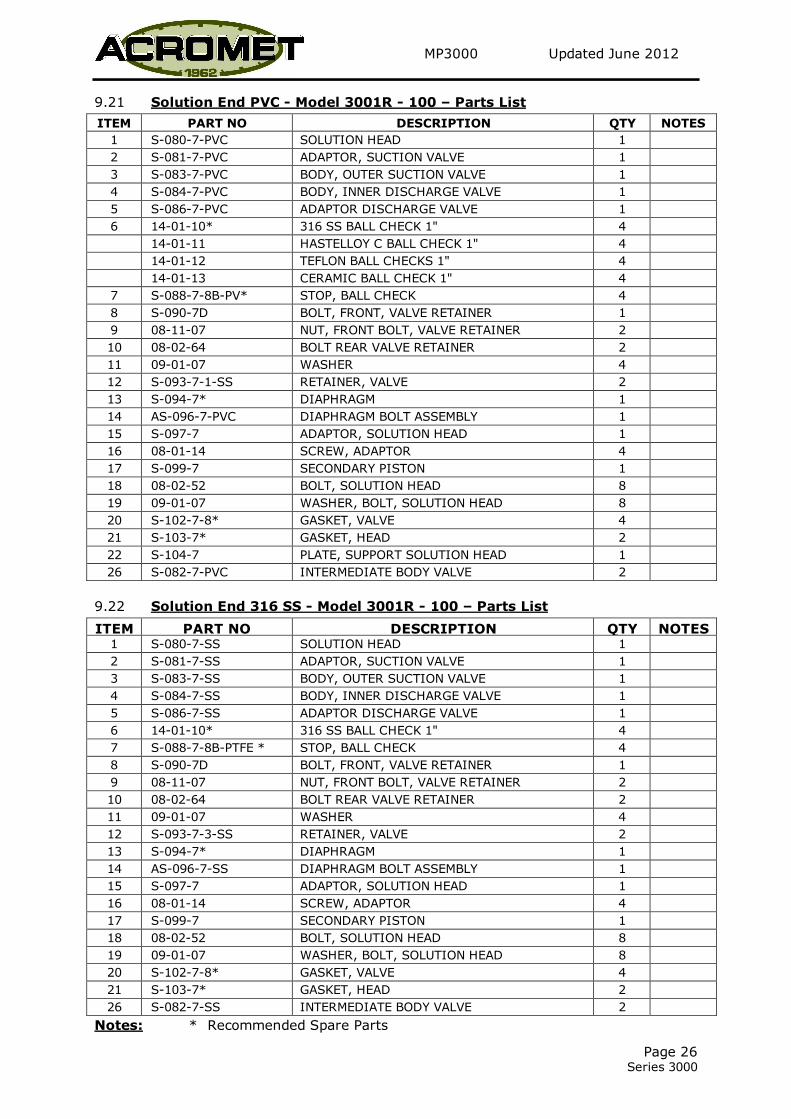
9.21 Solution End PVC - Model 3001R - 100 – Parts List
ITEM PART NO DESCRIPTION QTY NOTES
1 S-080-7-PVC SOLUTION HEAD 1
2 S-081-7-PVC ADAPTOR, SUCTION VALVE 1
3 S-083-7-PVC BODY, OUTER SUCTION VALVE 1
4 S-084-7-PVC BODY, INNER DISCHARGE VALVE 1
5 S-086-7-PVC ADAPTOR DISCHARGE VALVE 1
6 14-01-10* 316 SS BALL CHECK 1" 4
14-01-11 HASTELLOY C BALL CHECK 1" 4
14-01-12 TEFLON BALL CHECKS 1" 4
14-01-13 CERAMIC BALL CHECK 1" 4
7 S-088-7-8B-PV* STOP, BALL CHECK 4
8 S-090-7D BOLT, FRONT, VALVE RETAINER 1
9 08-11-07 NUT, FRONT BOLT, VALVE RETAINER 2
10 08-02-64 BOLT REAR VALVE RETAINER 2
11 09-01-07 WASHER 4
12 S-093-7-1-SS RETAINER, VALVE 2
13 S-094-7* DIAPHRAGM 1
14 AS-096-7-PVC DIAPHRAGM BOLT ASSEMBLY 1
15 S-097-7 ADAPTOR, SOLUTION HEAD 1
16 08-01-14 SCREW, ADAPTOR 4
17 S-099-7 SECONDARY PISTON 1
18 08-02-52 BOLT, SOLUTION HEAD 8
19 09-01-07 WASHER, BOLT, SOLUTION HEAD 8
20 S-102-7-8* GASKET, VALVE 4
21 S-103-7* GASKET, HEAD 2
22 S-104-7 PLATE, SUPPORT SOLUTION HEAD 1
26 S-082-7-PVC INTERMEDIATE BODY VALVE 2
9.22 Solution End 316 SS - Model 3001R - 100 – Parts List
ITEM PART NO DESCRIPTION QTY NOTES 1 S-080-7-SS SOLUTION HEAD 1
2 S-081-7-SS ADAPTOR, SUCTION VALVE 1
3 S-083-7-SS BODY, OUTER SUCTION VALVE 1
4 S-084-7-SS BODY, INNER DISCHARGE VALVE 1
5 S-086-7-SS ADAPTOR DISCHARGE VALVE 1
6 14-01-10* 316 SS BALL CHECK 1" 4
7 S-088-7-8B-PTFE * STOP, BALL CHECK 4
8 S-090-7D BOLT, FRONT, VALVE RETAINER 1
9 08-11-07 NUT, FRONT BOLT, VALVE RETAINER 2
10 08-02-64 BOLT REAR VALVE RETAINER 2
11 09-01-07 WASHER 4
12 S-093-7-3-SS RETAINER, VALVE 2
13 S-094-7* DIAPHRAGM 1
14 AS-096-7-SS DIAPHRAGM BOLT ASSEMBLY 1
15 S-097-7 ADAPTOR, SOLUTION HEAD 1
16 08-01-14 SCREW, ADAPTOR 4
17 S-099-7 SECONDARY PISTON 1
18 08-02-52 BOLT, SOLUTION HEAD 8
19 09-01-07 WASHER, BOLT, SOLUTION HEAD 8
20 S-102-7-8* GASKET, VALVE 4
21 S-103-7* GASKET, HEAD 2
26 S-082-7-SS INTERMEDIATE BODY VALVE 2
Notes: * Recommended Spare Parts
MP3000 Updated June 2012
Page 27 Series 3000
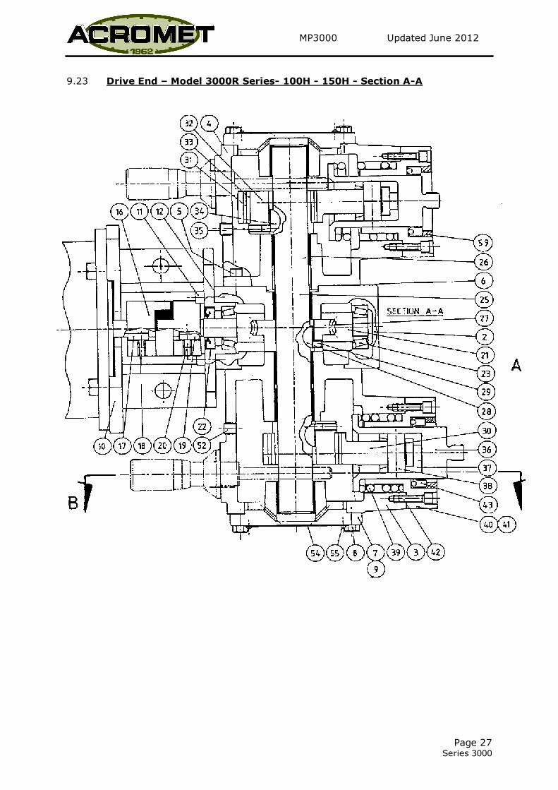
9.23 Drive End – Model 3000R Series- 100H - 150H - Section A-A
MP3000 Updated June 2012
Page 28 Series 3000
9.24 Drive End – Model 3000R Series – 100H Section A-A – Parts List
ITEM PART NO DESCRIPTION QTY NOTES
1 8800 GEARBOX (SIMPLEX) 1 A
2 8801 GEARBOX (DUPLEX)
3 8002 MULTIPLEX CHAMBER (SIMPLEX) 1
4 8001 MULTIPLEX CHAMBER (DUPLEX)
5 08-01-14 SCREWS MULTIPLEX CHAMBER 4
6 8019 * GASKETS 1
7 8003 END COVER 1
8 08-02-08 SCREWS END COVER 4
9 8019 * END COVER GASKET 1
10 8802 MOTOR SPOOL 1
11 08-01-15 SCREWS SPOOL 4
12 8803 * MOTOR SPOOL GASKET 1
16 9134 COUPLING 1
17 9120 KEY, MOTOR SHAFT (SUPPLIED WITH MOTOR) 1
18 08-13-01 SCREWS MOTOR SHAFT KEY 1
19 9121 KEY COUPLING (ON ASSEMBLY) 1
20 08-01-09 SCREW COUPLING 1
21 2802 WORM SHAFT 1 B
22 07-01-01 * OIL SEAL WORM SHAFT 1
23 06-01-12 * BEARING WORM SHAFT 2
24 8804 MAIN SHAFT (SIMPLEX) 1 A
25 8006 MAIN SHAFT (DUPLEX)
26 06-04-01 BUSH MAIN SHAFT 4
27 2021 WORM WHEEL 1 B
28 12-01-09 KEY WORM WHEEL 1
29 08-01-09 SCREW WORM WHEEL KEY 1
30 8209 CON ROD 1
Notes:
A Not Shown
B State Stroking Rate (SPM)
C State Size
* Recommended Spare Parts
MP3000 Updated June 2012
Page 29 Series 3000
9.25 Drive End – Model 3000R Series – 100H – 150H Section A-A - Parts List cont.
ITEM PART NO DESCRIPTION QTY NOTES
31 8216 BUSH CON ROD 1
32 8874-7-8H ECCENTRIC 1 C
33 06-05-02 LINER ECCENTRIC 1
34 12-01-09 KEY ECCENTRIC 1
35 08-13-01 SCREWS ECCENTRIC KEY 1
36 10000 PISTON PRIMARY 1
37 8026 CROSS HEAD 1
38 8024 PIN WRIST 1
39 8829 SPRING RETURN 1 C
40 8879 SLEEVE, PISTON 1
41 8831 GASKET, PISTON SLEEVE 1
42 08-01-17 SCREW PISTON SLEEVE 2
43 07-01-02 * SEAL PRIMARY PISTON 1
51 08-12-01 PLUG, DRAIN 2 A
52 08-12-02 PLUG 1
54 9111 PLATE, NAME 1
55 08-10-01 SCREW NAME PLATE 4
56 06-04-02 WRIST PIN BUSH 1
57 09-02-03 SPRING WASHER, MOTOR 4 A
58 08-08-10 THUMB SCREW, BARREL LOCK 1 A
59 8824 SEAL RING, PISTON SLEEVE 1
60 08-01-23 SCREW, ADAPTOR 4 A
Notes:
A Not Shown
B State Stroking Rate (SPM)
C State Size
* Recommended Spare Parts
MP3000 Updated June 2012
Page 30 Series 3000
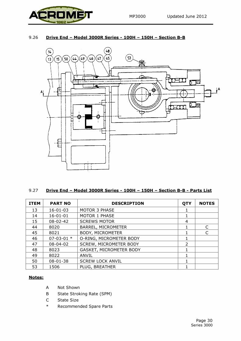
9.26 Drive End – Model 3000R Series - 100H – 150H – Section B-B
9.27 Drive End – Model 3000R Series - 100H – 150H – Section B-B - Parts List
ITEM PART NO DESCRIPTION QTY NOTES
13 16-01-03 MOTOR 3 PHASE 1
14 16-01-01 MOTOR 1 PHASE 1
15 08-02-42 SCREWS MOTOR 4
44 8020 BARREL, MICROMETER 1 C
45 8021 BODY, MICROMETER 1 C
46 07-03-01 * O-RING, MICROMETER BODY 1
47 08-04-02 SCREW, MICROMETER BODY 2
48 8023 GASKET, MICROMETER BODY 1
49 8022 ANVIL 1
50 08-01-38 SCREW LOCK ANVIL 1
53 1506 PLUG, BREATHER 1
Notes:
A Not Shown
B State Stroking Rate (SPM)
C State Size
* Recommended Spare Parts
MP3000 Updated June 2012
Page 31 Series 3000
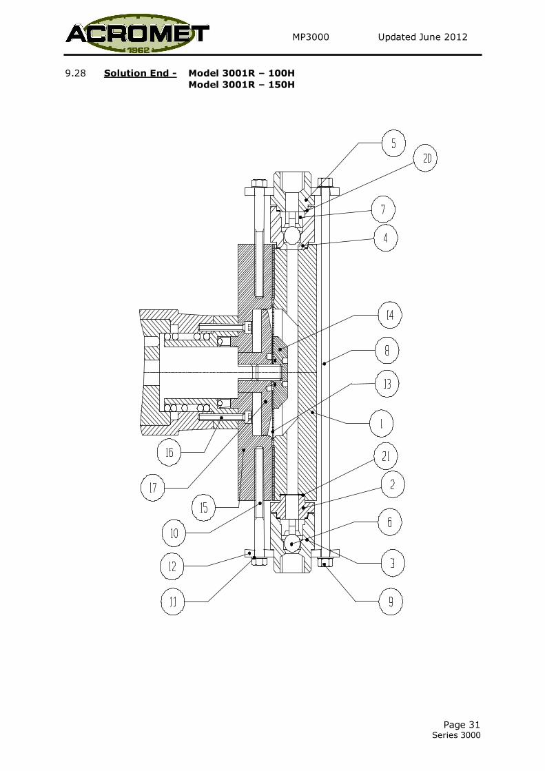
9.28 Solution End - Model 3001R – 100H
Model 3001R – 150H

MP3000 Updated June 2012
Page 32 Series 3000

MP3000 Updated June 2012
Page 33 Series 3000
9.29 Solution End PVC - Model 3001R – 100H – Parts List
ITEM PART NO DESCRIPTION QTY NOTES
1 S-080-7-PVC SOLUTION HEAD (150) 1
2 S-081-7-PVC ADAPTOR, SUCTION VALVE (150) 1
3 S-083-7H-PVC BODY, OUTER SUCTION VALVE(150) 1
4 S-084-7-PVC BODY, INNER DISCHARGE VALVE 1
5 S-086-7-PVC ADAPTOR DISCHARGE VALVE 1
6 14-01-10* 316 SS BALL CHECK 1" 2
14-01-11 HASTELLOY C BALL CHECK 1" 2
14-01-12 TEFLON BALL CHECKS 1" 2
14-01-13 CERAMIC BALL CHECK 1" 2
7 S-088-7-8B* STOP, BALL CHECK (100-150) 2
8 S-090-7D BOLT, FRONT, VALVE RETAINER 1
9 08-11-07 NUT, FRONT BOLT, VALVE RETAINER 2
10 08-02-58 BOLT REAR VALVE RETAINER 2
11 09-01-07 WASHER 4
12 S-093-7-1H-SS RETAINER, VALVE 2
13 S-094-7* DIAPHRAGM 1
14 AS-096-7-PVC DIAPHRAGM BOLT ASSEMBLY 1
15 S-097-7 ADAPTOR, SOLUTION HEAD 1
16 08-01-14 SCREW, ADAPTOR 4
17 S-099-7H SECONDARY PISTON 1
18 08-02-56 BOLT, SOLUTION HEAD 8
19 09-01-07 WASHER, SOLUTION HEAD 8
20 S-102-7-8* GASKET, VALVE 4
21 S-103-7* GASKET, HEAD 2
22 S-104-7 PLATE, SUPPORT SOLUTION HEAD (Not Shown) 1
9.30 Solution End 316 SS - Model 3001R – 100H– Parts List
ITEM PART NO DESCRIPTION QTY NOTES
1 S-080-7-SS SOLUTION HEAD 1
2 S-081-7-SS ADAPTOR, SUCTION VALVE 1
3 S-083-7H-SS BODY, OUTER SUCTION VALVE 1
4 S-084-7-SS BODY, INNER DISCHARGE VALVE 1
5 S-086-7-SS ADAPTOR DISCHARGE VALVE 1
6 14-01-10* 316 SS BALL CHECK 1" 2
7 S-088-7-8B-PTFE* STOP, BALL CHECK 2
8 S-090-7D BOLT, FRONT, VALVE RETAINER 1
9 08-11-07 NUT, FRONT BOLT, VALVE RETAINER 2
10 08-02-58 BOLT REAR VALVE RETAINER 2
11 09-01-07 WASHER 4
12 S-093-7-SS RETAINER, VALVE 2
13 S-094-7* DIAPHRAGM 1
14 AS-096-7-3H-SS DIAPHRAGM BOLT ASSEMBLY 1
15 S-097-7 ADAPTOR, SOLUTION HEAD 1
16 08-01-14 SCREW, ADAPTOR 4
17 S-099-7H SECONDARY PISTON 1
18 08-02-52 BOLT, SOLUTION HEAD 8
19 09-01-07 WASHER, SOLUTION HEAD 8
20 S-102-7-8* GASKET, VALVE 4
21 S-103-7* GASKET, HEAD 2
22 S-104-7 PLATE, SUPPORT SOLUTION HEAD (Not Shown) 1
Notes:
* Recommended Spare Parts
MP3000 Updated June 2012
Page 34 Series 3000
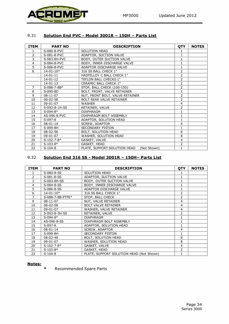
9.31 Solution End PVC - Model 3001R – 150H – Parts List
ITEM PART NO DESCRIPTION QTY NOTES
1 S-080-8-PVC SOLUTION HEAD 1
2 S-081-8-PVC ADAPTOR, SUCTION VALVE 1
3 S-083-8H-PVC BODY, OUTER SUCTION VALVE 1
4 S-084-8-PVC BODY, INNER DISCHARGE VALVE 1
5 S-086-8-PVC ADAPTOR DISCHARGE VALVE 1
6 14-01-10* 316 SS BALL CHECK 1" 2
14-01-11 HASTELLOY C BALL CHECK 1" 2
14-01-12 TEFLON BALL CHECKS 1" 2
14-01-13 CERAMIC BALL CHECK 1" 2
7 S-088-7-8B* STOP, BALL CHECK (100-150) 2
8 S-090-8D BOLT, FRONT, VALVE RETAINER 1
9 08-11-07 NUT, FRONT BOLT, VALVE RETAINER 2
10 08-02-58 BOLT REAR VALVE RETAINER 2
11 09-01-07 WASHER 4
12 S-093-8-1H-SS RETAINER, VALVE 2
13 S-094-8* DIAPHRAGM 1
14 AS-096-8-PVC DIAPHRAGM BOLT ASSEMBLY 1
15 S-097-8 ADAPTOR, SOLUTION HEAD 1
16 08-01-14 SCREW, ADAPTOR 4
17 S-099-8H SECONDARY PISTON 1
18 08-02-56 BOLT, SOLUTION HEAD 8
19 09-01-07 WASHER, SOLUTION HEAD 8
20 S-102-7-8* GASKET, VALVE 4
21 S-103-8* GASKET, HEAD 2
22 S-104-8 PLATE, SUPPORT SOLUTION HEAD (Not Shown) 1
9.32 Solution End 316 SS - Model 3001R – 150H– Parts List
ITEM PART NO DESCRIPTION QTY NOTES
1 S-080-8-SS SOLUTION HEAD 1
2 S-081-8-SS ADAPTOR, SUCTION VALVE 1
3 S-083-8H-SS BODY, OUTER SUCTION VALVE 1
4 S-084-8-SS BODY, INNER DISCHARGE VALVE 1
5 S-086-8-SS ADAPTOR DISCHARGE VALVE 1
6 14-01-10* 316 SS BALL CHECK 1" 2
7 S-088-7-8B-PTFE* STOP, BALL CHECK 2
9 08-11-07 NUT, VALVE RETAINER 4
10 08-02-58 BOLT VALVE RETAINER 4
11 09-01-07 WASHER, VALVE RETAINER 4
12 S-093-8-3H-SS RETAINER, VALVE 2
13 S-094-8* DIAPHRAGM 1
14 AS-096-8-SS DIAPHRAGM BOLT ASSEMBLY 1
15 S-097-8 ADAPTOR, SOLUTION HEAD 1
16 08-01-14 SCREW, ADAPTOR 4
17 S-099-8H SECONDARY PISTON 1
18 08-02-48 BOLT, SOLUTION HEAD 8
19 09-01-07 WASHER, SOLUTION HEAD 8
20 S-102-7-8* GASKET, VALVE 4
21 S-103-8* GASKET, HEAD 2
22 S-104-8 PLATE, SUPPORT SOLUTION HEAD (Not Shown) 1
Notes:
* Recommended Spare Parts
MP3000 Updated June 2012
Page 35 Series 3000
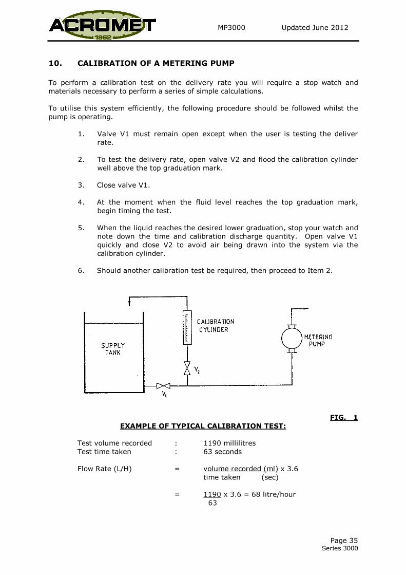
10. CALIBRATION OF A METERING PUMP
To perform a calibration test on the delivery rate you will require a stop watch and
materials necessary to perform a series of simple calculations.
To utilise this system efficiently, the following procedure should be followed whilst the
pump is operating.
1. Valve V1 must remain open except when the user is testing the deliver
rate.
2. To test the delivery rate, open valve V2 and flood the calibration cylinder
well above the top graduation mark.
3. Close valve V1.
4. At the moment when the fluid level reaches the top graduation mark,
begin timing the test.
5. When the liquid reaches the desired lower graduation, stop your watch and
note down the time and calibration discharge quantity. Open valve V1
quickly and close V2 to avoid air being drawn into the system via the
calibration cylinder.
6. Should another calibration test be required, then proceed to Item 2.
FIG. 1
EXAMPLE OF TYPICAL CALIBRATION TEST:
Test volume recorded : 1190 millilitres
Test time taken : 63 seconds
Flow Rate (L/H) = volume recorded (ml) x 3.6
time taken (sec)
= 1190 x 3.6 = 68 litre/hour
63
MP3000 Updated June 2012
Page 36 Series 3000
CALIBRATION CYLINDER – INSTALLATION GUIDE
LOCATION:
Install the calibration cylinder as shown in Figure 1. The cylinders must be installed in
the suction piping in a vertical position and as close as possible to the suction tank.
Remember the location should make allowance for sufficient free space around the
calibration cylinder for easy reading of graduations.
PIPING:
It is essential that the size of the pipe to the calibration cylinder be the same size as the
suction piping and cylinder inlet connection. Under-sized pipe work will cause suction
losses and, hence, affect calibration accuracy.
We strongly recommend that the use of full-flow ball valves to give consistent system
throughput and rapid open and shut operation – an important feature when checking
calibrations.
Piping should be air-tight and suitably supported at regular intervals.
An overflow/venting line should be connected between the top of the calibration cylinder
and the supply tank.
CAUTION: NEVER USE THE CYLINDER ON THE DISCHARGE SIDE OF ANY
PUMP.

MP3000 Updated June 2012
Page 37 Series 3000
11. SERIES 500 VALVE INSTRUCTIONS
INSTALLATION:
See diagram overleaf of recommended installation layout for pressure relief and back
pressure applications.
We recommend installation of a pulsation dampener between valve and pump for both
applications to provide smoother, more accurate valve operation and maximise valve life.
Coat pipe fittings with suitable thread sealant such as PTFE tape before connecting to
prevent leakage.
CAUTION: Do not over-tighten screwed connection. Should leakage occur
during operation, unfasten connection and recoat threads with
sealant.
ADJUSTMENT:
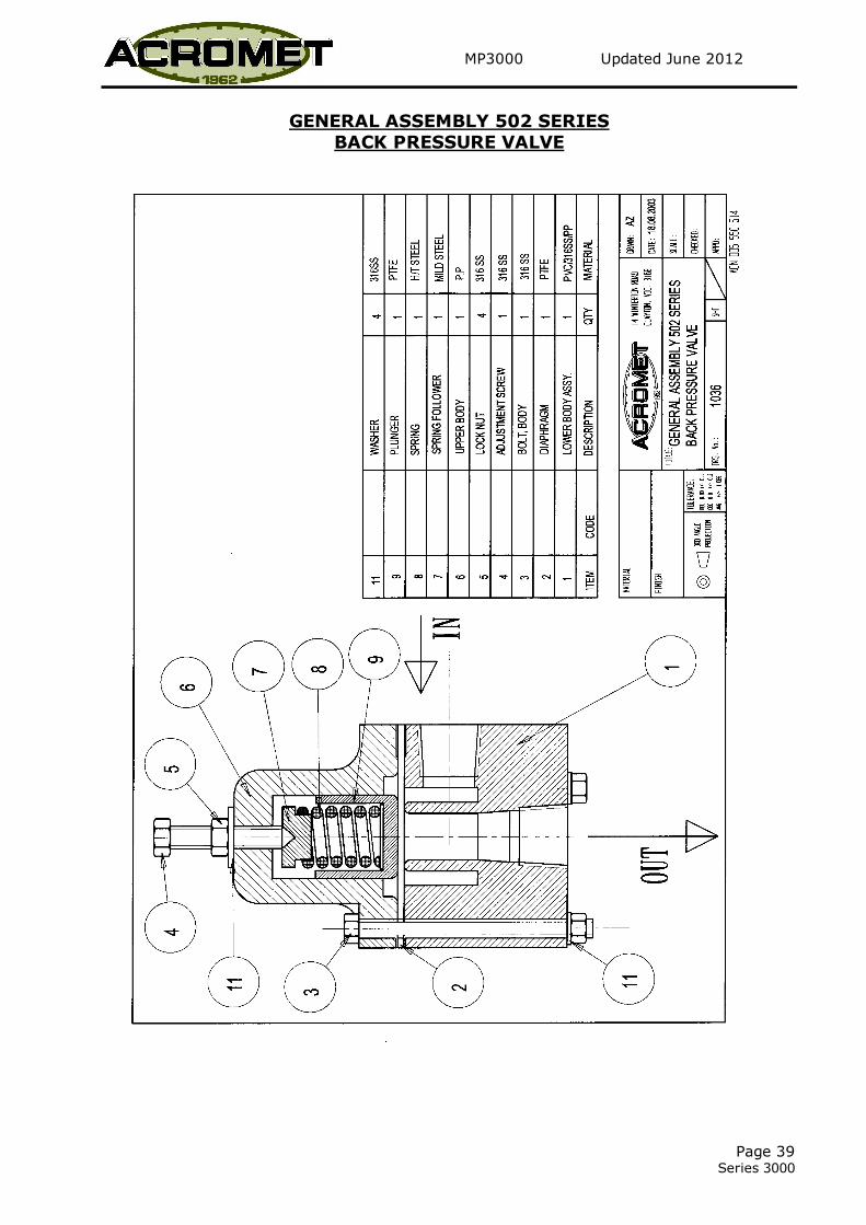
Valve operating pressure is controlled by the spring (8) and can be increased or
decreased by varying the spring preload.
At date of purchase, Acromet will adjust the valve to meet customer's requirements.
To alter or set operating pressure at site, it is necessary for a pressure gauge with
snubber to be installed in the line between the valve and the pump and with pump
operating:-
For Back Pressure: Unfasten locknut (5). Unscrew adjustment screw (4) to
decrease pressure or screw in to increase pressure. When required pressure is
achieved, retighten locknut.
For Pressure Relief: Unfasten locknut. Unscrew adjustment screw to
decrease pressure or screw in to increase pressure. When full flow through
valve at required relief pressure is achieved, retighten locknut.
MAINTENANCE:
The valve and its components should be inspected annually or when incorrect operation
is suspected.
Disassembly is relatively simple. Unfasten locknut and unscrew adjustment screw to
remove spring preload. Unfasten the three main bolts (3). These bolts hold the upper
and lower halves together. Separate body halves and remove internals.
Carefully inspect and clean all components. Worn or damaged parts should be replaced.
Smear the outer surface of the plunger and the bore of the upper body with grease to
prevent plunger sticking in bore during operation.
Assembly procedure is reverse of disassembly.
After reinstalling, adjust valve operating pressure as previously described.

MP3000 Updated June 2012
Page 38 Series 3000
INSTALLATION LAYOUT
1. Supply Tank
2. Metering Pump
3. Pressure Relief Valve
4. Pulsation Dampener
5. Back Pressure Valve
6. Pressure Gauge
MP3000 Updated June 2012
Page 39 Series 3000
GENERAL ASSEMBLY 502 SERIES
BACK PRESSURE VALVE

MP3000 Updated June 2012
Page 40 Series 3000
GENERAL ASSEMBLY 502 SERIES PRESSURE RELIEF VALVE

MP3000 Updated June 2012
Page 40 Series 3000
APPENDIX

MP3000 Updated June 2012
Page 41
Series 3000
1 EQUIPMENT DECONTAMINATION PROCEDURE DOC. No. QAPM-SD-19.0-1

MP3000 Updated June 2012
Page 42 Series 3000
2 EQUIPMENT DECONTAMINATION ADVICE DOC. No. SD-19.0-1