Embed Size (px)
Citation preview
PNNL-15992
300 Area Pacific Northwest National Laboratory Facility Radionuclide Emission Points and Sampling Systems B. C. Barfuss J. M. Barnett L. J. Harbinson August 2006 Prepared for the U.S. Department of Energy under Contract DE-AC05-76RL01830
DISCLAIMER This report was prepared as an account of work sponsored by an agency of the United States Government. Neither the United States Government nor any agency thereof, nor Battelle Memorial Institute, nor any of their employees, makes any warranty, express or implied, or assumes any legal liability or responsibility for the accuracy, completeness, or usefulness of any information, apparatus, product, or process disclosed, or represents that its use would not infringe privately owned rights. Reference herein to any specific commercial product, process, or service by trade name, trademark, manufacturer, or otherwise does not necessarily constitute or imply its endorsement, recommendation, or favoring by the United States Government or any agency thereof, or Battelle Memorial Institute. The views and opinions of authors expressed herein do not necessarily state or reflect those of the United States Government or any agency thereof. PACIFIC NORTHWEST NATIONAL LABORATORY operated by BATTELLE for the UNITED STATES DEPARTMENT OF ENERGY under Contract DE-ACO5-76RL01830
Printed in the United States of America
Available to DOE and DOE contractors from the Office of Scientific and Technical Information,
P.O. Box 62, Oak Ridge, TN 37831-0062; ph: (865) 576-8401 fax: (865) 576 5728
email: [email protected]
Available to the public from the National Technical Information Service, U.S. Department of Commerce, 5285 Port Royal Rd., Springfield, VA 22161
ph: (800) 553-6847 fax: (703) 605-6900
email: [email protected] online ordering: http://www.ntis.gov/ordering.htm
PNNL-15992
300 Area Pacific Northwest National Laboratory Facility Radionuclide Emission Points and Sampling Systems B. C. Barfuss J. M. Barnett L. J. Harbinson August 2006 Prepared for the U.S. Department of Energy under Contract DE-AC05-76RL01830 Pacific Northwest National Laboratory Richland, Washington 99352
iii
SUMMARY The Battelle Northwest Operations division operates numerous research and development laboratories in Richland, Washington, including those associated with the Pacific Northwest National Laboratory (PNNL) on the Department of Energy’s Hanford Site that have the potential for radionuclide air emissions. The National Emission Standard for Hazardous Air Pollutants (NESHAP 40 CFR 61, Subparts H and I) requires an assessment of all effluent release points that have the potential for radionuclide emissions. Potential emissions are assessed annually. Sampling, monitoring, and other regulatory-compliance requirements are designated based upon the potential-to-emit dose criteria found in the regulations. The purpose of this document is to describe the facility radionuclide air emission-sampling program and provide current and historical facility emission point system performance, operation, and design information. A description of the exhaust points, control technologies, and sample extraction details is provided for each registered or deregistered facility emission point. Additionally, applicable stack-sampler-configuration drawings, figures, and photographs are provided.

v
TABLE OF CONTENTS SUMMARY................................................................................................................................................... iii GLOSSARY AND LIST OF TERMS ........................................................................................................... vii INTRODUCTION.......................................................................................................................................... 1 BACKGROUND ........................................................................................................................................... 2 COMPLIANCE REQUlREMENTS ............................................................................................................... 3 SAMPLING SYSTEM DESIGN.................................................................................................................... 4 STACK VELOCITY AND CYCLONIC FLOW MEASUREMENTS............................................................... 5 SAMPLING PROGRAM............................................................................................................................... 5 SCHEDULE.................................................................................................................................................. 5 PARTICULATE SAMPLE COLLECTION AND ANALYSIS ......................................................................... 5 TRITIUM SAMPLE COLLECTION AND ANALYSIS ................................................................................... 5 PROCEDURES............................................................................................................................................ 6 SAMPLE SYSTEM PERFORMANCE.......................................................................................................... 6 POTENTIAL OFFSITE DOSE AND PRINCIPLE RADIONUCLIDES.......................................................... 7 LIST OF TABLES......................................................................................................................................... 9 REFERENCES........................................................................................................................................... 17 APPENDIX A PARTICULATE SAMPLE ANALYSIS AND DATA EVALUATION..................................... 19 APPENDIX B TRITIUM SAMPLE ANALYSIS AND DATA EVALUATION ............................................... 21 APPENDIX C MISCELLANEOUS DRAWINGS OF STANDARD COMPONENTS FOR
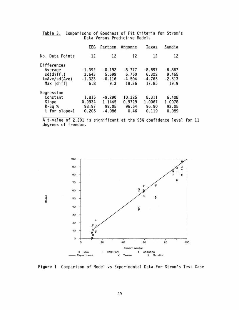
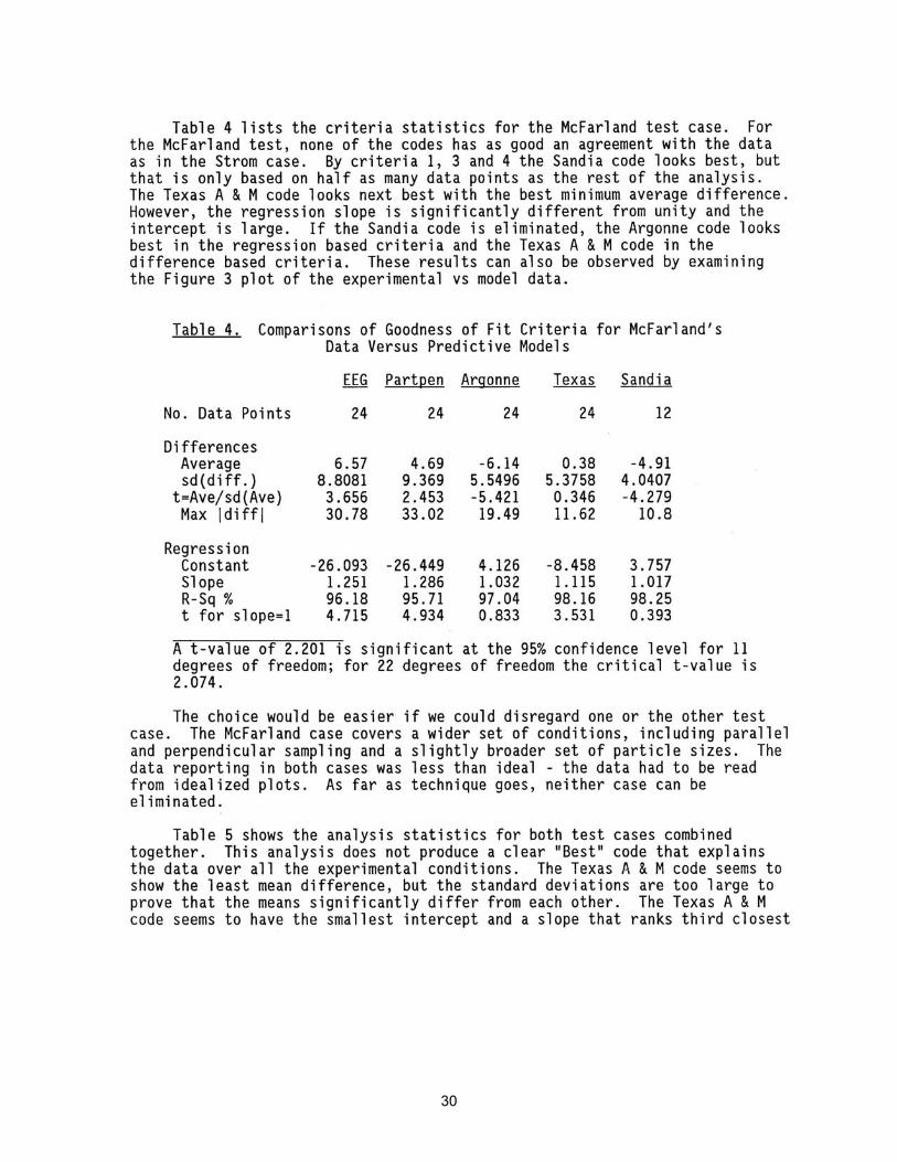
UPGRADED STACK SAMPLING SYSTEMS.................................................................... 23 APPENDIX D RECOMMENDATION OF PARTICLE LINE-LOSS CODE................................................ 25 APPENDIX E DEPARTMENT OF ENERGY STACK SAMPLER SYSTEMS........................................... 39 APPENDIX F BATTELLE PRIVATE STACK SAMPLER SYSTEMS...................................................... 113

vii
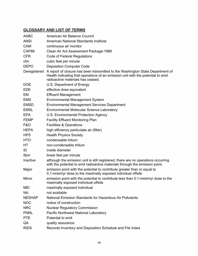
GLOSSARY AND LIST OF TERMS AABC American Air Balance Council ANSI American National Standards Institute CAM continuous air monitor CAP88 Clean Air Act Assessment Package-1988 CFR Code of Federal Regulations cfm cubic feet per minute DEPO Deposition Computer Code Deregistered A report of closure has been transmitted to the Washington State Department of
Health indicating that operations of an emission unit with the potential to emit radioactive materials has ceased.
DOE U.S. Department of Energy EDE effective dose equivalent EM Effluent Management EMS Environmental Management System EMSD Environmental Management Services Department EMSL Environmental Molecular Science Laboratory EPA U.S. Environmental Protection Agency FEMP Facility Effluent Monitoring Plan F&O Facilities & Operations HEPA high efficiency particulate air (filter) HPS Health Physics Society HTO condensable tritium HT non-condensable tritium ID inside diameter Ifpm linear feet per minute Inactive although the emission unit is still registered, there are no operations occurring
with the potential to emit radioactive materials through the emission point. Major emission point with the potential to contribute greater than or equal to
0.1-mrem/yr dose to the maximally exposed individual offsite Minor emission point with the potential to contribute less than 0.1-mrem/yr dose to the
maximally exposed individual offsite MEI maximally exposed individual NA not available NESHAP National Emission Standards for Hazardous Air Pollutants NOC notice of construction NRC Nuclear Regulatory Commission PNNL Pacific Northwest National Laboratory PTE Potential to emit QA quality assurance RIDS Records Inventory and Disposition Schedule and File Index
viii
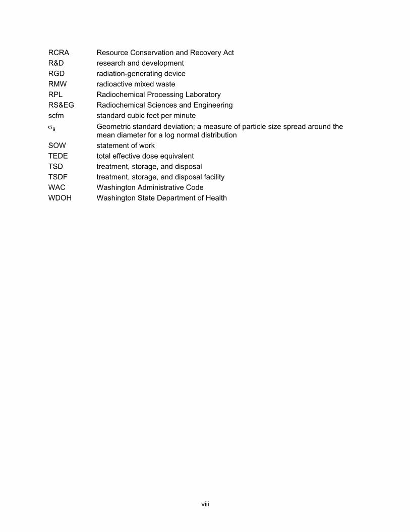
RCRA Resource Conservation and Recovery Act R&D research and development RGD radiation-generating device RMW radioactive mixed waste RPL Radiochemical Processing Laboratory RS&EG Radiochemical Sciences and Engineering scfm standard cubic feet per minute σg Geometric standard deviation; a measure of particle size spread around the
mean diameter for a log normal distribution SOW statement of work TEDE total effective dose equivalent TSD treatment, storage, and disposal TSDF treatment, storage, and disposal facility WAC Washington Administrative Code WDOH Washington State Department of Health
1
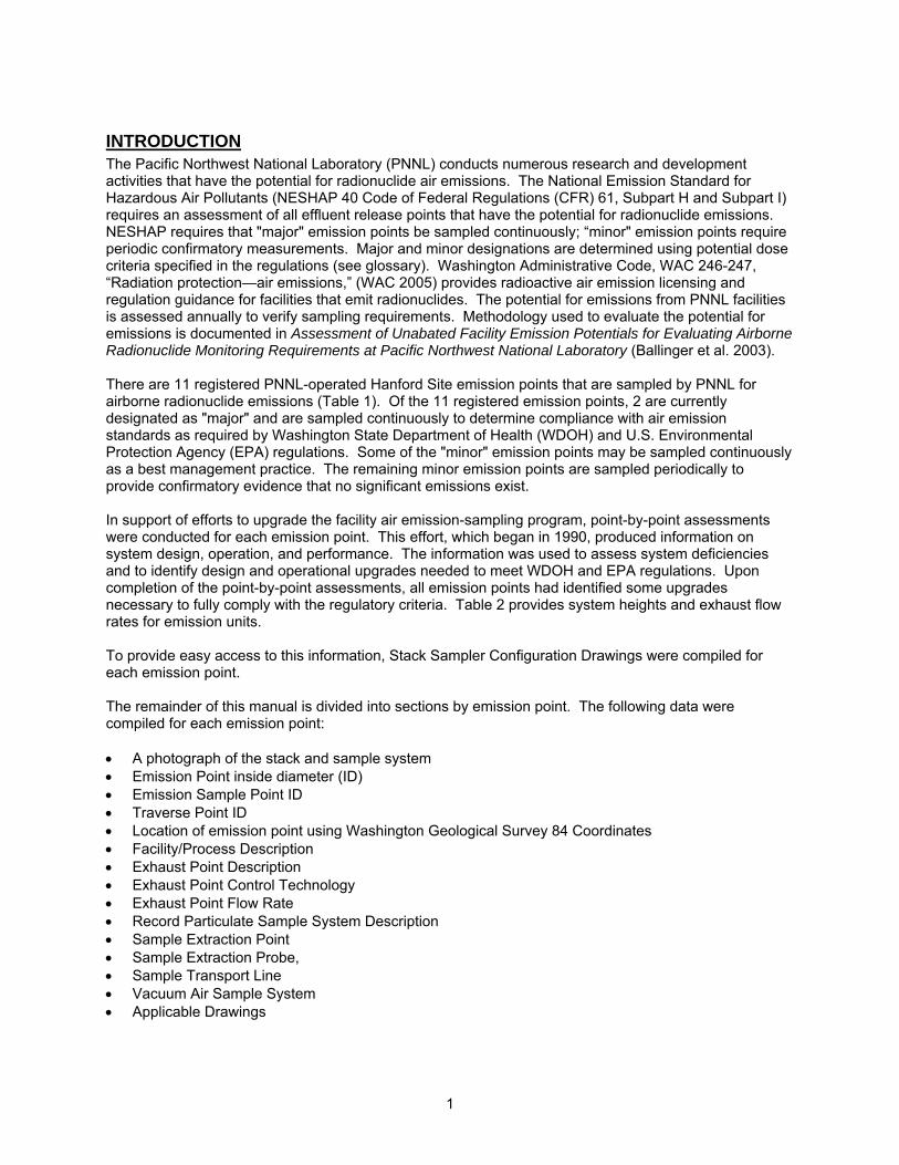
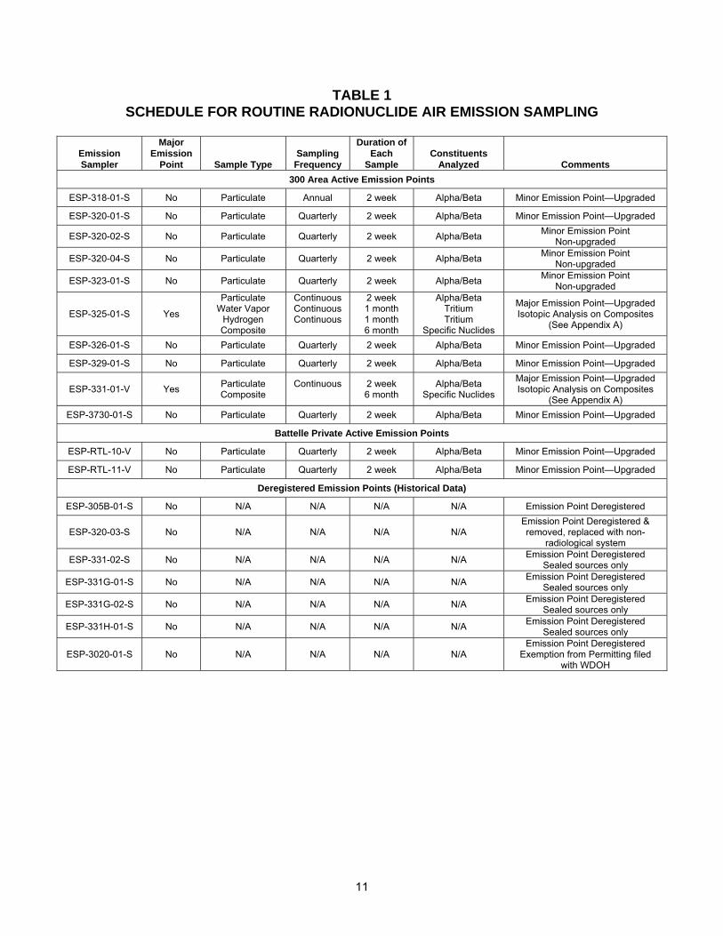
INTRODUCTION The Pacific Northwest National Laboratory (PNNL) conducts numerous research and development activities that have the potential for radionuclide air emissions. The National Emission Standard for Hazardous Air Pollutants (NESHAP 40 Code of Federal Regulations (CFR) 61, Subpart H and Subpart I) requires an assessment of all effluent release points that have the potential for radionuclide emissions. NESHAP requires that "major" emission points be sampled continuously; “minor" emission points require periodic confirmatory measurements. Major and minor designations are determined using potential dose criteria specified in the regulations (see glossary). Washington Administrative Code, WAC 246-247, “Radiation protection—air emissions,” (WAC 2005) provides radioactive air emission licensing and regulation guidance for facilities that emit radionuclides. The potential for emissions from PNNL facilities is assessed annually to verify sampling requirements. Methodology used to evaluate the potential for emissions is documented in Assessment of Unabated Facility Emission Potentials for Evaluating Airborne Radionuclide Monitoring Requirements at Pacific Northwest National Laboratory (Ballinger et al. 2003). There are 11 registered PNNL-operated Hanford Site emission points that are sampled by PNNL for airborne radionuclide emissions (Table 1). Of the 11 registered emission points, 2 are currently designated as "major" and are sampled continuously to determine compliance with air emission standards as required by Washington State Department of Health (WDOH) and U.S. Environmental Protection Agency (EPA) regulations. Some of the "minor" emission points may be sampled continuously as a best management practice. The remaining minor emission points are sampled periodically to provide confirmatory evidence that no significant emissions exist. In support of efforts to upgrade the facility air emission-sampling program, point-by-point assessments were conducted for each emission point. This effort, which began in 1990, produced information on system design, operation, and performance. The information was used to assess system deficiencies and to identify design and operational upgrades needed to meet WDOH and EPA regulations. Upon completion of the point-by-point assessments, all emission points had identified some upgrades necessary to fully comply with the regulatory criteria. Table 2 provides system heights and exhaust flow rates for emission units. To provide easy access to this information, Stack Sampler Configuration Drawings were compiled for each emission point. The remainder of this manual is divided into sections by emission point. The following data were compiled for each emission point: • A photograph of the stack and sample system • Emission Point inside diameter (ID) • Emission Sample Point ID • Traverse Point ID • Location of emission point using Washington Geological Survey 84 Coordinates • Facility/Process Description • Exhaust Point Description • Exhaust Point Control Technology • Exhaust Point Flow Rate • Record Particulate Sample System Description • Sample Extraction Point • Sample Extraction Probe, • Sample Transport Line • Vacuum Air Sample System • Applicable Drawings
2
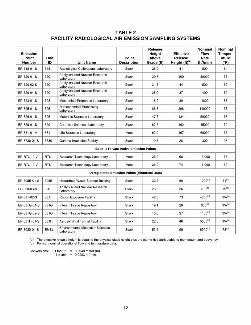
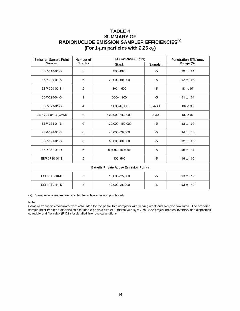
BACKGROUND In response to plans by the EPA to revise the emission sampling regulations, PNNL initiated a comprehensive effort to upgrade facility radionuclide emission sampling systems in 1990. The EPA regulations were issued as 40 CFR 61, “National Emission Standard for Hazardous Air Pollutants" (December 15, 1989). Subpart H, “National Emission Standards for Emissions of Radionuclides Other Than Radon from Department of Energy Facilities,” applied to many PNNL-operated facilities at Hanford. Subpart I, “National Emission Standards fro Radionuclide Emissions from Federal Facilities Other Than Nuclear Regulatory Commission Licensees and Not Covered by Subpart H,” applied to many PNNL-operated private facilities. The U.S. Department of Energy (DOE) subsequently published DOE Order 5400.5, "Radiation Protection of the Public and the Environment” (February 8, 1990). Additionally, Washington State promulgated (WAC 246-247 Radiation Protection—Air Emissions) radioactive air emissions requirements in 1994 detailing licensing requirements and regulation guidance applicable to PNNL facilities that emit radionuclides. Most PNNL sampling systems were originally designed to be operated at a nominal sample rate of 2 cubic feet per minute (cfm); that is, the sample probe nozzles were sized to operate isokinetically at a sample rate of 2 cfm. However, changes in facility ventilation flow rates, degradation of the sampler vacuum supply, or compliance with ANSI N13.1–1999, can result in deviation from the original isokinetic design. Accurate setting of sample rates to achieve isokinetic sampling conditions requires that the exhaust system velocity be measured at the sample extraction location. Before 1990, facility exhaust flow rates were measured for purposes of ventilation system control using methods prescribed by the American Air Balance Council (AABC). The AABC measurements were generally performed at locations other than the point of sample extraction. Although these measurements were useful for establishing volumetric discharge rates, they were not appropriate for establishing sampling rates. In support of the overall upgrade effort, airborne radionuclide emission sampling systems were inspected during the summer of 1990. Sample probes were removed from stacks and/or ducts for visual inspection; sampler nozzle and sample transport line dimensions were measured; and sampler location, orientation, and configuration were recorded. Whenever possible, exhaust system velocities and volumetric flow rates were determined using Determination of Stack Gas Velocity and Volumetric Flow Rate (40 CFR 60 Appendix A-1, Method 2). Since then, flow rates have been measured at least annually. Information obtained during sampler inspections and stack velocity measurements was used with the Deposition (DEPO) computer code to estimate the deposition of particles collected in each sampling system. Since 1990, the sampling systems have been periodically evaluated for sampling error caused by sampling system line losses using the DEPO code. Table 4 summarizes the most recent evaluation. In addition, cyclonic flow measurements were conducted for each sampling system according to 40 CFR 60 Appendix A, Method 1, Section 11.4. Table 3 summarizes the results of these measurements. As a result of the 1990 assessments, a list of upgrades to radionuclide emission sampling systems was developed. The listed upgrades were those necessary for compliance with the NESHAP regulations and DOE guidance in DOE/EH-0173T (DOE 1991). The upgrades were completed using a graded approach based on the release potential; emission points with minimal release potential were not upgraded. The stack sampler configuration sheets, along with supporting data, document the information resulting from the before-mentioned assessments and subsequent upgrades.
3
COMPLIANCE REQUIREMENTS The primary drivers for the facility airborne radionuclide emission sampling and monitoring program are: • 40 CFR 61, Subpart H “National Emission Standards for Emissions of Radionuclides other than
Radon from Department of Energy Facilities” applies to DOE-owned or -operated facilities that emit radionuclides other than radon-222 and radon-220 to the air and require 1) evaluating potential radiological air emission sources for impact to the public and environment, 2) sampling release streams, 3) registering certain sources and emissions, 4) filing notices of construction for new and or modified sources, 5) complying with the 10-mrem release standard, 6) evaluating best available control technology, 7) reporting emissions, and 8) maintaining a quality assurance program.
• 40 CFR 61, Subpart I “National Emission Standards fro Radionuclide Emissions from Federal
Facilities Other Than Nuclear Regulatory Commission Licensees and Not Covered by Subpart H,” applies to facilities owned or operated by any Federal agency other than DOE and 1) require complying with the 10-mrem release standard, 2) reporting emissions, and 3) maintaining a quality assurance program.
• WAC 246-247 “Radiation Protection—Air Emissions” provides licensing requirements for
1) monitoring facility radioactive air emissions, 2) evaluating potential radiological air emission sources for impact to the public and environment, 3) sampling release streams, 4) filing notices of construction for new and or modified sources, 5) complying with the 10-mrem release standard, 6) evaluating best available control technology, 7) reporting emissions, and 8) maintaining a quality assurance program.
• 40 CFR 70 “State Operating Permit Programs” provides for maintaining state air operating permit
programs, demonstrating emission levels, and complying with permit conditions as applicable. • WAC 173-401 “Operating Permit Regulation” program (WAC 1993) requires applying for an air
operating permit, demonstrating emission levels, and complying with permit conditions as applicable. • DOE Order 450.1 “Environmental Protection Program” (DOE 2003) approved 1-15-03 to replace
DOE 5400.1 requires DOE sites to implement an Environmental Management System (EMS) as part of an Integrated Safety Management System. The EMS is a continuing cycle of planning, implementing, evaluating, and improving processes and actions undertaken to achieve environmental goals.
• DOE Order 5400.5 “Radiation Protection of the Public and the Environment” establishes standards
for DOE operations and DOE contractors with respect to protection of members of the public and the environment against undue risk from radiation. Major portions of this order are not in the PNNL contract, thus the application is minimal.
• DOE 5480.19 “Conduct of Operations Requirements for DOE Facilities” (DOE 2001) establishes
requirements for the conduct of operations at DOE facilities to verify acceptable operations, provide for continuing improvements in the operations, and verify the maintenance of acceptable margins of safety.
• DOE/EH-0173T "Environmental Regulatory Guide for Radiological Effluent Monitoring and
Environmental Surveillance” establishes elements of a radiological effluent monitoring and surveillance program considered acceptable to DOE, in support of DOE 5400.5 “Radiation Protection of the Public and the Environment” (DOE 1993) and DOE 5400.1 “General Environmental Protection Program” (DOE 1990).
Facility airborne radionuclide emission sampling requirements are derived from 40 CFR 61, Subpart H. The regulation requires:
4
• Continuous sampling at airborne emission points for which annual emissions could result in a potential effective dose equivalent to an offsite individual of 0.1 mrem/yr or more.
• When continuous sampling is required, all radionuclides that contribute greater than 10 percent of the
potential-to-emit (PTE) total effective dose equivalent (TEDE) to the maximally exposed individual (MEI), greater than 0.1 mrem/yr PTE TEDE to the MEI, and greater than 25 percent of the TEDE to the MEI after controls for a release point shall be measured.
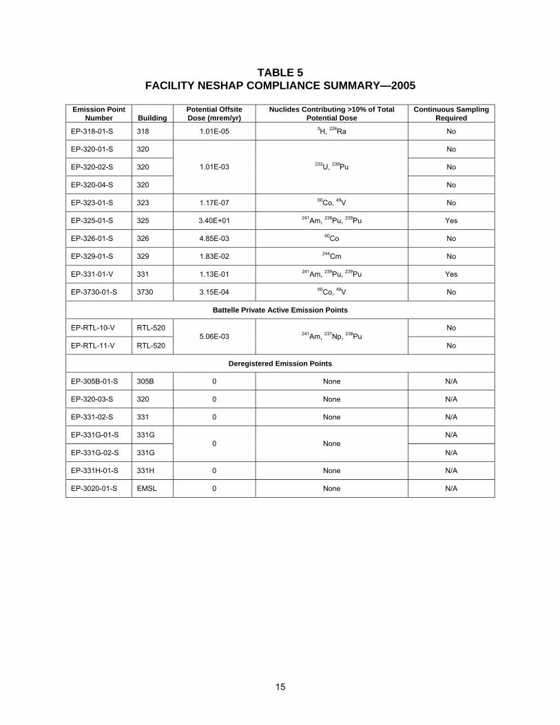
The potential effective dose equivalent to an offsite individual is based on a projection of the emissions that could result during normal operations and anticipated process upsets, assuming all pollution control equipment (e.g., high efficiency particulate air filter [HEPA]) did not exist. For EPA regulations, the MEI is a member of the public at any offsite point where there is a residence, school, business, or office. For the Washington State regulations, the MEI is any member of the public who abides or resides in an unrestricted area. The MEI is therefore assumed to be onsite when DOE leases a facility space on the Hanford Site to non-contractor organizations. The potential effective dose equivalent to an offsite individual for each PNNL facility was established in 1991 as part of the PNNL Facility Effluent Monitoring Plan (FEMP) determination process. Facility emission rates were projected based on radionuclide quantities within each facility. Offsite doses were calculated using the EPA Clean Air Act Assessment Package-1988 (CAP88) computer model. Since 1993, doses have been modeled using CAP88-PC for DOE sites and COMPLY for private facilities. These determinations are updated annually. Table 5 summarizes the airborne emission compliance determinations. Facilities with potential annual emissions below the 0.1-mrem/yr offsite dose level are excluded from the continuous compliance sampling requirements of 40 CFR 61, Subpart H and I. However, periodic confirmatory measurements are required at these locations to demonstrate that emissions are minimal relative to emission standards. Before 1996, PNNL sampled radionuclide emission sources on a continuous basis, regardless of significance. Beginning in 1996, PNNL implemented a program of sampling radionuclide emissions based on the NESHAP's designation of "major" and "minor" sources. Continuous radionuclide sampling is conducted on all emission points designated as "major." The criteria found in PNNL Potential Impact Categories are to be considered when setting sampling requirements. Washington State regulations primarily reflect federal regulations, but are also allowed to be more stringent than federal regulations. EPA recently granted partial approval to WDOH’s request for program approval and delegation of authority to implement and enforce the Radionuclide NESHAPs program. EPA’s partial approval and delegation to WDOH transfers primary implementation and enforcement responsibility for the Radionuclide NESHAPs program to WDOH (71 FR 32276-32282).
SAMPLING SYSTEM DESIGN Both federal and state regulations incorporate American National Standards Institute (ANSI) N13.1-1969 for sampling system design requirements. In September 2002, federal regulations adopted ANSI/HPS N13.1-1999 (ANSI/HPS 1999) for new or modified systems. Data on sampler design characteristics were obtained from facility safety analysis reports, engineering drawings, vendor design documents, and system inspections. In the 1990 and 1991 inspections, whenever possible, the sampling probe was removed from the stack or duct for inspection. For systems installed after 1990 and 1991, Effluent Management (EM) has been involved with the facility modification process to verify that systems are designed and installed as required and that design drawings are maintained (e.g., Leeper et al. 1993). At present, only the 325 Building emission unit is required to comply with ANSI/HPS N13.1-1999.
5
STACK VELOCITY AND CYCLONIC FLOW MEASUREMENTS The stack velocity and cyclonic flow conditions at the sample extraction point are measured according to 40 CFR 60, Appendix A-1 method 2. PNNL Facilities & Operations (F&O) staff performs these measurements in support of the effluent monitoring task. The following PNNL procedures were derived from the regulatory guides and are used by the F&O Air Balance staff: • EMS-AIR-016 “PNNL Stack/Duct Velocity Traverse Method” • EMS-AIR-017 “Verification of Absence of Cyclonic Flow Conditions in Stacks and Vents”
• EMS-AIR-019 “Standard and Type-S Pitot Tube Specifications Inspection Procedure”
SAMPLING PROGRAM SCHEDULE
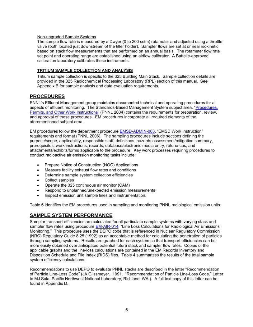
The basic sampling schedule is provided in Table 1. The sampling program includes:
• Continuous Sampling—the sampler is operated continuously throughout the year. The sample is exchanged approximately every 2 weeks.
• Quarterly Sampling—a sample is collected every quarter for a 2-week period.
• Annual Sampling—a sample is collected once a year for a 2-week period.
• Special Sampling—a sample is collected as needed to follow up on sampler problems or
investigate anomalies in sample results.
• Other Sampling—a sample may be collected from system cleaning or other activity or study.
PARTICULATE SAMPLE COLLECTION AND ANALYSIS
Particulate record samples are collected using a 47-mm membrane filter (Gelman Sciences Versapor-Membrane, acrylic copolymer membrane filter) supported by a modified (upgraded systems) or standard (non-upgraded systems) filter holder. The membrane filter has an estimated retention efficiency of greater than 91% for 0.3-micron particles. Two-week particulate samples are collected on an annual, quarterly, or continuous basis to confirm that emissions are below the 0.1-mrem/yr offsite dose. Sample systems are inspected for proper flow-rate settings and system operation on a daily basis, excluding weekends and holidays, during sampling events. Sample systems are enclosed in metal cabinets for protection from inclement weather. The operation of the sampling systems varies because of the differences in sample system components (upgraded and non-upgraded). See Appendix A for sample analysis and data evaluation requirements and Table 1 for a listing of upgraded and non-upgraded sample systems. Upgraded Sample Systems The sample flow rate is measured by a Brooks Instrument GT-1000 (0.586 to 5.86 standard cubic feet per minute [scfm]) rotameter and adjusted using a throttle valve (both located just downstream of the filter holder). A vacuum gauge (0 to 100 in. of water) is installed on the inlet side of the rotameter and used to correct the sample flow for vacuum conditions. Sampler flows are set at or near isokinetic based on stack flow measurements that are performed on an annual basis. The rotameter and vacuum gauge are calibrated and exchanged on an annual basis. A Battelle-approved calibration laboratory calibrates these instruments. See Appendix C for drawings of standard components for upgraded sampling systems.
6
Non-upgraded Sample Systems The sample flow rate is measured by a Dwyer (0 to 200 scfm) rotameter and adjusted using a throttle valve (both located just downstream of the filter holder). Sampler flows are set at or near isokinetic based on stack flow measurements that are performed on an annual basis. The rotameter flow rate set point and operating range are established using an airflow calibrator. A Battelle-approved calibration laboratory calibrates these instruments.
TRITIUM SAMPLE COLLECTION AND ANALYSIS Tritium sample collection is specific to the 325 Building Main Stack. Sample collection details are provided in the 325 Radiochemical Processing Laboratory (RPL) section of this manual. See Appendix B for sample analysis and data-evaluation requirements.
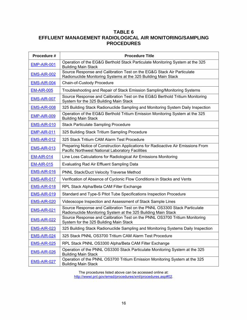
PROCEDURES PNNL’s Effluent Management group maintains documented technical and operating procedures for all aspects of effluent monitoring. The Standards-Based Management System subject area, “Procedures, Permits, and Other Work Instructions” (PNNL 2004) contains the requirements for preparation, review, and approval of these procedures. EM procedures incorporate all required elements of the aforementioned subject area. EM procedures follow the department procedure EMSD-ADMIN-003, “EMSD Work Instruction” requirements and format (PNNL 2006). The sampling procedures include sections defining the purpose/scope, applicability, responsible staff, definitions, hazards assessment/mitigation summary, prerequisites, work instructions, records, database/electronic media entry, references, and attachments/exhibits/forms applicable to the procedure. Key work processes requiring procedures to conduct radioactive air emission monitoring tasks include:
• Prepare Notice of Construction (NOC) Applications • Measure facility exhaust flow rates and conditions • Determine sample system collection efficiencies • Collect samples • Operate the 325 continuous air monitor (CAM) • Respond to unplanned/unexpected emission measurements • Inspect emission unit sample lines and instrumentation.
Table 6 identifies the EM procedures used in sampling and monitoring PNNL radiological emission units.
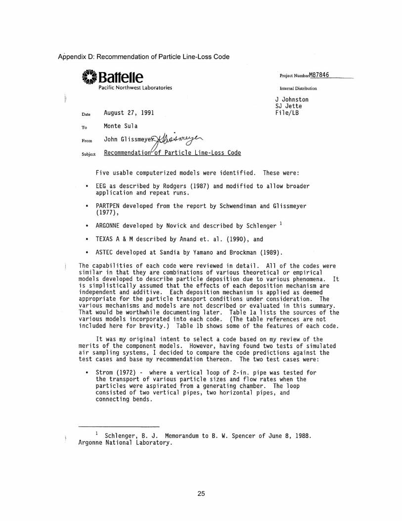
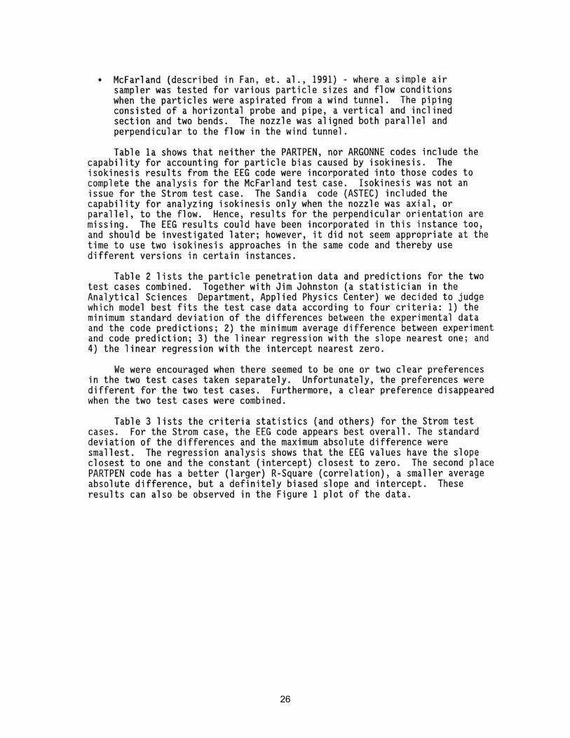
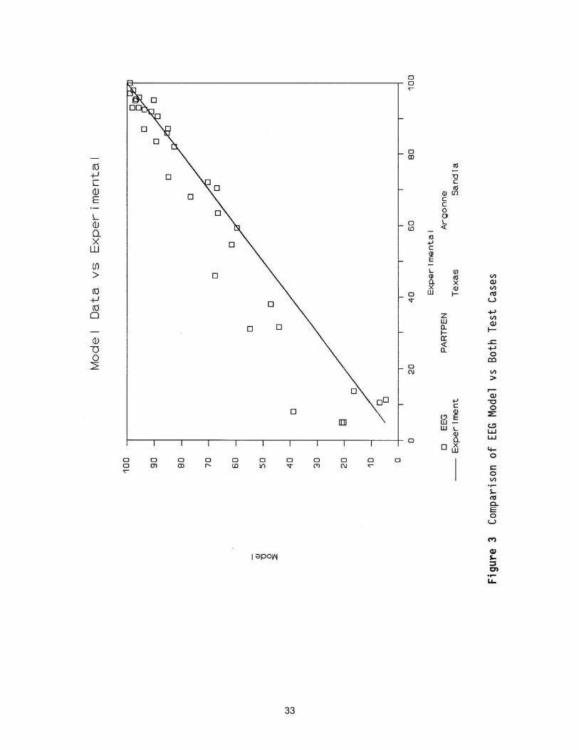
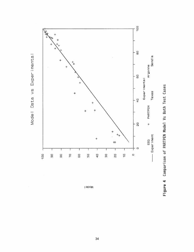
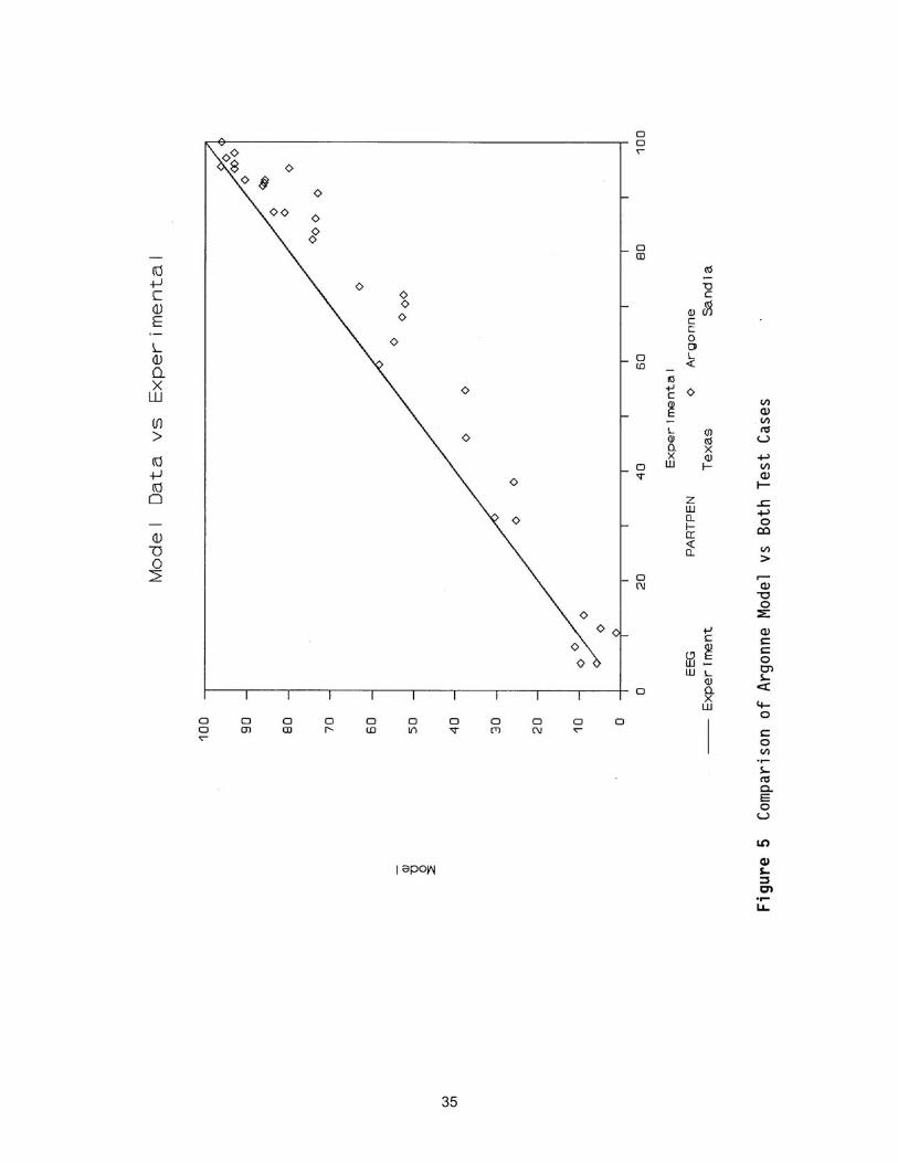
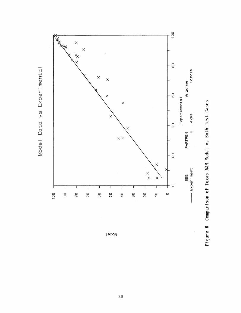
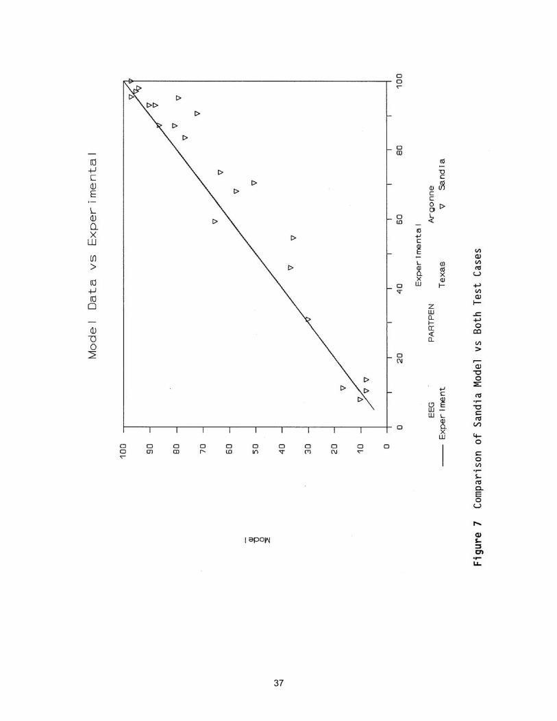
SAMPLE SYSTEM PERFORMANCE Sampler transport efficiencies are calculated for all particulate sample systems with varying stack and sampler flow rates using procedure EM-AIR-014, “Line Loss Calculations for Radiological Air Emissions Monitoring.” This procedure uses the DEPO code that is referenced in Nuclear Regulatory Commission (NRC) Regulatory Guide 8.25 (1992) as an acceptable method for calculating the penetration of particles through sampling systems. Results are graphed for each system so that transport efficiencies can be more easily obtained over anticipated potential future stack and sampler flow rates. Copies of the applicable graphs and the line-loss calculations are contained in the EM Records Inventory and Disposition Schedule and File Index (RIDS) files. Table 4 summarizes the results of the total sample system efficiency calculations. Recommendations to use DEPO to evaluate PNNL stacks are described in the letter “Recommendation of Particle Line-Loss Code” (JA Glissmeyer. 1991. “Recommendation of Particle Line-Loss Code.” Letter to MJ Sula, Pacific Northwest National Laboratory, Richland, WA.). A full text copy of this letter can be found in Appendix D.

7
POTENTIAL OFFSITE DOSE AND PRINCIPLE RADIONUCLIDES The potential effective dose equivalent (EDE) to an individual is an inventory-based projection of the emissions that could result during normal operations, assuming the emissions are not reduced by installed emission control equipment. A radionuclide inventory assessment is performed on an annual basis to determine facility potential-to-emit (in mrem/yr). This assessment is used to verify compliance with the EPA and Washington State Department of Health permits and to determine the need for continuous compliance sampling (40 CFR 61, Subpart H). The results of past and current annual NESHAPS assessments are provided through the following links:
│2005│ 2004 │ 2003 │ 2002 │ 2001 │ 2000 │ 1999 │


9
LIST OF TABLES Table 1 Schedule for Routine Radionuclide Air Emission Sampling Table 2 Facility Radiological Air Emission Sampling Systems Table 3 Verification of Absence of Cyclonic Flow Conditions in Stacks and Vents Table 4 Summary of Radionuclide Air Emission Sampler Efficiencies Table 5 Facility NESHAP Compliance Summary—2005 Table 6 Effluent Management Radiological Air Monitoring/Sampling Procedures

11
TABLE 1 SCHEDULE FOR ROUTINE RADIONUCLIDE AIR EMISSION SAMPLING
Emission Sampler
Major Emission
Point Sample Type Sampling Frequency
Duration of Each
Sample Constituents
Analyzed Comments 300 Area Active Emission Points
ESP-318-01-S No Particulate Annual 2 week Alpha/Beta Minor Emission Point—Upgraded ESP-320-01-S No Particulate Quarterly 2 week Alpha/Beta Minor Emission Point—Upgraded
ESP-320-02-S No Particulate Quarterly 2 week Alpha/Beta Minor Emission Point Non-upgraded
ESP-320-04-S No Particulate Quarterly 2 week Alpha/Beta Minor Emission Point Non-upgraded
ESP-323-01-S No Particulate Quarterly 2 week Alpha/Beta Minor Emission Point Non-upgraded
ESP-325-01-S Yes
Particulate Water Vapor
Hydrogen Composite
Continuous Continuous Continuous
2 week 1 month 1 month 6 month
Alpha/Beta Tritium Tritium
Specific Nuclides
Major Emission Point—Upgraded Isotopic Analysis on Composites
(See Appendix A)
ESP-326-01-S No Particulate Quarterly 2 week Alpha/Beta Minor Emission Point—Upgraded
ESP-329-01-S No Particulate Quarterly 2 week Alpha/Beta Minor Emission Point—Upgraded
ESP-331-01-V Yes Particulate Composite
Continuous
2 week 6 month
Alpha/Beta Specific Nuclides
Major Emission Point—Upgraded Isotopic Analysis on Composites
(See Appendix A) ESP-3730-01-S No Particulate Quarterly 2 week Alpha/Beta Minor Emission Point—Upgraded
Battelle Private Active Emission Points
ESP-RTL-10-V No Particulate Quarterly 2 week Alpha/Beta Minor Emission Point—Upgraded
ESP-RTL-11-V No Particulate Quarterly 2 week Alpha/Beta Minor Emission Point—Upgraded
Deregistered Emission Points (Historical Data)
ESP-305B-01-S No N/A N/A N/A N/A Emission Point Deregistered
ESP-320-03-S No N/A N/A N/A N/A Emission Point Deregistered & removed, replaced with non-
radiological system
ESP-331-02-S No N/A N/A N/A N/A Emission Point Deregistered Sealed sources only
ESP-331G-01-S No N/A N/A N/A N/A Emission Point Deregistered Sealed sources only
ESP-331G-02-S No N/A N/A N/A N/A Emission Point Deregistered Sealed sources only
ESP-331H-01-S No N/A N/A N/A N/A Emission Point Deregistered Sealed sources only
ESP-3020-01-S No N/A N/A N/A N/A Emission Point Deregistered
Exemption from Permitting filed with WDOH
12
TABLE 2 FACILITY RADIOLOGICAL AIR EMISSION SAMPLING SYSTEMS
Emission Point
Number Unit ID Unit Name
Point Description
Release Height above
Grade (ft)
Effective Release
Height (ft)(a)
Nominal Flow Rate
(ft3/min)
Nominal Temper-
ature (ºF)
EP-318-01-S 318 Radiological Calibrations Laboratory Stack 28.9 41 500 84
EP-320-01-S 320 Analytical and Nuclear Research Laboratory Stack 39.7 100 30000 75
EP-320-02-S 320 Analytical and Nuclear Research Laboratory Stack 31.8 44 500 82
EP-320-04-S 320 Analytical and Nuclear Research Laboratory Stack 26.0 37 400 82
EP-323-01-S 323 Mechanical Properties Laboratory Stack 16.2 30 1800 88
EP-325-01-S 325 Radiochemical Processing Laboratory Stack 88.8 268 140000 76
EP-326-01-S 326 Materials Sciences Laboratory Stack 47.7 134 50000 78
EP-329-01-S 329 Chemical Sciences Laboratory Stack 62.5 162 45000 79
EP-331-01-V 331 Life Sciences Laboratory Vent 62.0 167 60000 77
EP-3730-01-S 3730 Gamma Irradiation Facility Stack 19.3 28 300 93
Battelle Private Active Emission Points
EP-RTL-10-V RTL Research Technology Laboratory Vent 26.0 68 15,000 77
EP-RTL-11-V RTL Research Technology Laboratory Vent 26.0 74 17,000 80
Deregistered Emission Points (Historical Data)
EP-305B-01-S 305B Hazardous Waste Storage Building Stack 32.8 50 1000(b) 81(b)
EP-320-03-S 320 Analytical and Nuclear Research Laboratory Stack 26.0 36 400(b) 79(b)
EP-331-02-S 331 Radon Exposure Facility Stack 42.3 73 4800(b) N/A(b)
EP-331G-01-S 331G Interim Tissue Repository Stack 19.1 28 600(b) N/A(b)
EP-331G-02-S 331G Interim Tissue Repository Stack 15.0 27 1400(b) N/A(b)
EP-331H-01-S 331H Aerosol Wind Tunnel Facility Stack 22.0 46 5500(b) N/A(b)
EP-3020-01-S EMSL Environmental Molecular Sciences Laboratory Stack 53.6 99 6900(b) 78(b)
(a) The effective release height is equal to the physical stack height plus the plume rise attributable to momentum and buoyancy. (b) Former nominal operational flow and temperature data. Conversions: 1 foot (ft) = 0.3048 meter (m) 1 ft3/min = 0.0283 m3/min.
13
TABLE 3 VERIFICATION OF ABSENCE OF CYCLONIC FLOW CONDITIONS
IN STACKS AND VENTS
Emission Point
Number Unit Name Traverse
Point Date
Average Yaw Angle (degrees)
Acceptable (Yes/No)(a)
EP-318-01-S Radiological Calibrations Laboratory TP-318-01-1 06/22/2006 12.2 Yes
EP-320-01-S Analytical and Nuclear Research Laboratory TP-320-01-1 10/12/2000 3.4 Yes
EP-320-02-S Analytical and Nuclear Research Laboratory TP-320-02-1 07/20/1999 0.75 Yes
EP-320-04-S Analytical and Nuclear Research Laboratory TP-320-04-1 07/20/1999 1.35 Yes
EP-323-01-S Mechanical Properties Laboratory TP-323-01-1 01/27/2000 7.45 Yes
EP-325-01-S Radiochemical Processing Laboratory TP-325-01-1 01/27/1999 0.0 Yes
EP-326-01-S Materials Sciences Laboratory TP-326-01-1 03/30/2000 6.05 Yes
EP-329-01-S Chemical Sciences Laboratory TP-329-01-1 01/27/2000 3.85 Yes
EP-331-01-V Life Sciences Laboratory TP-331-01-1 08/02/2000 10.6 Yes
EP-3730-01-S Gamma Irradiation Facility TP-3730-01-1 07/20/1999 10.4 Yes
Battelle Private Active Emission Points
EP-RTL-10-V Research Technology Laboratory TP-RTL-10-1 09/20/1999 5.9 Yes
EP-RTL-11-V Research Technology Laboratory TP-RTL-11-1 09/20/1999 5.2 Yes
Deregistered Emission Points (Historical Data)
EP-305B-01-S Hazardous Waste Storage Building TP-305B-01-1 05/12/1999 4.25 Yes
EP-320-03-S Analytical and Nuclear Research Laboratory TP-320-03-1 07/20/1999 2.8 Yes
EP-331-02-S Radon Exposure Facility TP-331-02-1 06/08/1999 2.2 Yes
EP-331G-01-S Interim Tissue Repository TP-331G-01-1 06/07/1999 9.0 Yes
EP-331G-02-S Interim Tissue Repository TP-331G-02-1 06/07/1999 3.5 Yes
EP-331H-01-S Aerosol Wind Tunnel Facility TP-331H-01-1 06/07/1999 9.3 Yes
EP-3020-01-S Environmental Molecular Sciences Laboratory TP-3020-01-1 01/12/2000 2.1 Yes
(a) If the average Yaw angle is > 20 degrees, then the overall flow condition in the stack is unacceptable. If the average Yaw angle is ≤ 20 degrees, then the flow condition in the stack is acceptable.
14
TABLE 4 SUMMARY OF
RADIONUCLIDE EMISSION SAMPLER EFFICIENCIES(a) (For 1-μm particles with 2.25 σg)
FLOW RANGE (cfm) Emission Sample Point
Number Number of
Nozzles Stack Sampler Penetration Efficiency
Range (%)
ESP-318-01-S 2 300–800 1-5 93 to 101
ESP-320-01-S 6 20,000–50,000 1-5 92 to 108
ESP-320-02-S 2 300 – 600 1-5 83 to 97
ESP-320-04-S 1 300–1,200 1-5 81 to 101
ESP-323-01-S 4 1,000–6,000 0.4-3.4 86 to 98
ESP-325-01-S (CAM) 6 120,000–150,000 5-30 95 to 97
ESP-325-01-S 6 120,000–150,000 1-5 93 to 109
ESP-326-01-S 6 40,000–70,000 1-5 94 to 110
ESP-329-01-S 6 30,000–60,000 1-5 92 to 108
ESP-331-01-D 6 50,000–100,000 1-5 95 to 117
ESP-3730-01-S 2 100–500 1-5 96 to 102
Battelle Private Active Emission Points
ESP-RTL-10-D 5 10,000–25,000 1-5 93 to 119
ESP-RTL-11-D 5 10,000–25,000 1-5 93 to 119
(a) Sampler efficiencies are reported for active emission points only. Note: Sampler transport efficiencies were calculated for the particulate samplers with varying stack and sampler flow rates. The emission sample point transport efficiencies assumed a particle size of 1 micron with σg = 2.25. See project records inventory and disposition schedule and file index (RIDS) for detailed line-loss calculations.
15
TABLE 5 FACILITY NESHAP COMPLIANCE SUMMARY—2005
Emission Point
Number Building Potential Offsite Dose (mrem/yr)
Nuclides Contributing >10% of Total Potential Dose
Continuous Sampling Required
EP-318-01-S 318 1.01E-05 3H, 226Ra No
EP-320-01-S 320 No
EP-320-02-S 320 No
EP-320-04-S 320
1.01E-03 233U, 239Pu
No
EP-323-01-S 323 1.17E-07 60Co, 49V No
EP-325-01-S 325 3.40E+01 241Am, 238Pu, 239Pu Yes
EP-326-01-S 326 4.85E-03 60Co No
EP-329-01-S 329 1.83E-02 244Cm No
EP-331-01-V 331 1.13E-01 241Am, 238Pu, 239Pu Yes
EP-3730-01-S 3730 3.15E-04 60Co, 49V No
Battelle Private Active Emission Points
EP-RTL-10-V RTL-520 No
EP-RTL-11-V RTL-520 5.06E-03 241Am, 237Np, 238Pu
No
Deregistered Emission Points
EP-305B-01-S 305B 0 None N/A
EP-320-03-S 320 0 None N/A
EP-331-02-S 331 0 None N/A
EP-331G-01-S 331G N/A
EP-331G-02-S 331G 0 None
N/A
EP-331H-01-S 331H 0 None N/A
EP-3020-01-S EMSL 0 None N/A
16
TABLE 6 EFFLUENT MANAGEMENT RADIOLOGICAL AIR MONITORING/SAMPLING
PROCEDURES
Procedure # Procedure Title
EMP-AIR-001 Operation of the EG&G Berthold Stack Particulate Monitoring System at the 325 Building Main Stack
EMS-AIR-002 Source Response and Calibration Test on the EG&G Stack Air Particulate Radionuclide Monitoring Systems at the 325 Building Main Stack
EMS-AIR-004 Chain-of-Custody Procedure
EM-AIR-005 Troubleshooting and Repair of Stack Emission Sampling/Monitoring Systems
EMS-AlR-007 Source Response and Calibration Test on the EG&G Berthold Tritium Monitoring System for the 325 Building Main Stack
EMS-AIR-008 325 Building Stack Radionuclide Sampling and Monitoring System Daily Inspection
EMP-AlR-009 Operation of the EG&G Berthold Tritium Emission Monitoring System at the 325 Building Main Stack
EMS-AIR-010 Stack Particulate Sampling Procedure
EMP-AlR-011 325 Building Stack Tritium Sampling Procedure
EMS-AlR-012 325 Stack Tritium CAM Alarm Test Procedure
EMS-AlR-013 Preparing Notice of Construction Applications for Radioactive Air Emissions From Pacific Northwest National Laboratory Facilities
EM-AIR-014 Line Loss Calculations for Radiological Air Emissions Monitoring
EM-AIR-015 Evaluating Rad Air Effluent Sampling Data
EMS-AIR-016 PNNL Stack/Duct Velocity Traverse Method
EMS-AIR-017 Verification of Absence of Cyclonic Flow Conditions in Stacks and Vents
EMS-AIR-018 RPL Stack Alpha/Beta CAM Filter Exchange
EMS-AIR-019 Standard and Type-S Pitot Tube Specifications Inspection Procedure
EMS-AIR-020 Videoscope Inspection and Assessment of Stack Sample Lines
EMS-AIR-021 Source Response and Calibration Test on the PNNL OS3300 Stack Particulate Radionuclide Monitoring System at the 325 Building Main Stack
EMS-AIR-022 Source Response and Calibration Test on the PNNL OS3700 Tritium Monitoring System for the 325 Building Main Stack
EMS-AIR-023 325 Building Stack Radionuclide Sampling and Monitoring Systems Daily Inspection
EMS-AIR-024 325 Stack PNNL OS3700 Tritium CAM Alarm Test Procedure
EMS-AIR-025 RPL Stack PNNL OS3300 Alpha/Beta CAM Filter Exchange
EMS-AIR-026 Operation of the PNNL OS3300 Stack Particulate Monitoring System at the 325 Building Main Stack
EMS-AIR-027 Operation of the PNNL OS3700 Tritium Emission Monitoring System at the 325 Building Main Stack
The procedures listed above can be accessed online at:
http://wwwi.pnl.gov/emsd/procedures/xml/procedures.asp#02.
17
REFERENCES 40 CFR 60. 1971. U.S. Environmental Protection Agency. “Regulations on Standards of Performance for New Stationary Sources, Appendix A: Reference Methods.” U.S. Code of Federal Regulations. 40 CFR 61, Appendix B, Method 114. 2002. U.S. Environmental Protection Agency. “Test Methods for Measuring Radionuclide Emissions from Stationary Sources.” U.S. Code of Federal Regulations. 40 CFR 61, Subpart H 2002. U.S. Environmental Protection Agency. “National Emission Standards for Emissions of Radionuclides Other Than Radon from Department of Energy Facilities.” U.S. Code of Federal Regulations. 40 CFR 61, Subpart I 2002. U.S. Environmental Protection Agency. “National Emission Standards for Radionuclide Emissions from Federal Facilities Other Than Nuclear Regulatory Commission Licensees and Not Covered by Subpart H.” U.S. Code of Federal Regulations. 40 CFR 70. 1992. U.S. Environmental Protection Agency. “State Operating Permit Programs.” U.S. Code of Federal Regulations. 71 FR 32276-32282. June 5, 2006. “Partial Approval of the Clean Air Act, Section 112(l), Delegation of Authority to the Washington State Department of Health.” Federal Register, U.S. Environmental Protection Agency. American National Standards Institute (ANSI). 1970. Guide to Sampling Airborne Radioactive Materials in Nuclear Facilities. ANSI N13.1-1969. American National Standards Institute/Health Physics Society (ANSI/HPS). 1999. Sampling and Monitoring Releases of Airborne Radioactive Substances from the Stacks and Ducts of Nuclear Facilities. ANSI/HPS N13.1-1999. Ballinger MY, MJ Sula, TL Gervais, and DL Edwards. 2003. Assessment of Unabated Facility Emission Potentials for Evaluating Airborne Radionuclide Monitoring Requirements at Pacific Northwest National Laboratory. PNL-10855, Richland, WA. Leeper J, R Jones, R Gurke, and J Gaston. 1993. Install Isokinetic Stack Sampler. Battelle Project (# D00133-EDP01-R5), Pacific Northwest National Laboratory, Richland, WA. Pacific Northwest National Laboratory (PNNL). 2004. “Procedures, Permits, and Other Work Instructions.” Standards-Based Management System Subject Area (http://sbms.pnl.gov/standard/74/7400t010.htm), Richland, WA. Pacific Northwest National Laboratory (PNNL). 2006. “EMSD Work Instruction.” EM/EMSD Procedures (http://wwwi.pnl.gov/emsd/procedures/xml/procedures.asp#03), Richland, WA. U.S. Department of Energy (DOE). 1990. “General Environmental Protection Program.” DOE Order 5400.1 Change 1. Washington, D.C. U.S. Department of Energy (DOE). 1991. Environmental Regulatory Guide for Radiological Effluent Monitoring and Environmental Surveillance. DOE/EH-0173T, Washington, D.C. U.S. Department of Energy (DOE). 1993. “Radiation Protection of the Public and the Environment.” DOE Order 5400.5 Change 2. Washington, D.C. U.S. Department of Energy (DOE). 2001. “Conduct of Operations Requirements for DOE Facilities.” DOE Order 5480.19 Change 2. Washington, D.C.
18
U.S. Department of Energy (DOE). 2003. “Environmental Protection Program.” DOE Order 450.1. Washington, D.C. U.S. Nuclear Regulatory Commission (NRC). 1992. Air Sampling in the Workplace. NRC Regulatory Guide 8.25. Washington Administrative Code (WAC). 1993. “Operating Permit Regulation.” WAC 173-401, Olympia, WA. Washington Administrative Code (WAC). 2005. “Radiation Protection—Air Emissions.” WAC 246-247, Olympia, WA.
19
Appendix A: Particulate Sample Analysis and Data Evaluation
The Radiochemical Sciences and Engineering (RS&EG) group of the Pacific Northwest National Laboratory’s (PNNL’s) Radiochemical Processing Laboratory (RPL) performs particulate sample analyses. All analytical work associated with radionuclide sampling is performed according to required methods per the PNNL statement of work (SOW) "Airborne Radionuclide Emission Sample Analysis.” The SOW is prepared to meet the Quality Assurance (QA) Requirements from 40 CFR 61, Appendix B, Method 114. The analytical laboratory performs analysis on samples for the PNNL Effluent Management (EM) group per the aforementioned SOW. Procedures maintained by analytical lab staff are used to analyze the samples. After collection, the sample filter is typically stored for 5 days to permit decay of radon and thoron daughter radionuclides. Each sample is individually counted for gross alpha and gross beta activity. The analytical laboratory staff use direct counting methods for total alpha and total beta activity using a solid-state gas-flow proportional alpha-beta coincidence counter. The counter is calibrated using 238Pu for alpha and 90Sr for beta. Detection levels of 1 E-15 μCi/mL alpha and 3 E-15 μCi/mL beta are typically achieved. In addition to the above individual sample analyses, particulate samples from "major" stacks are combined and analyzed semi-annually as a single “composite” sample for specific radionuclides as determined by the annual inventory assessment. A composite sample consists of 6-months worth of individual samples (typically January through June and July through December). Radionuclides that contribute greater than 10 percent of the potential-to-emit (PTE) total effective dose equivalent (TEDE) to the maximally exposed individual (MEI), greater than 0.1 mrem/yr potential-to-emit TEDE to the MEI, and greater than 25 percent of the TEDE to the MEI after controls for a release point are analyzed isotopically. Specific nuclide analysis is accomplished by destructive analysis of the filters. The analytical laboratory documents detection levels for specific isotopes. The sample results obtained are used to evaluate existing facility emission levels and to calculate annual emission quantities for compliance determination and reporting purposes. Data are evaluated using documented and approved procedures. Data-evaluation procedures are based on guidance in DOE/EH - 0173T. Airborne emission sampling data are reviewed for anomalies and trends. Release data are updated throughout the sampling year (calendar year) as data are received. At the completion of the calendar year, data are reviewed, and results are finalized. Anomalous data are investigated and documented. Final release quantities include corrections for isokinetic sampling efficiency, sample transport losses, sample self-absorption, decay, counting efficiency, background, and collection media efficiency.

21
Appendix B: Tritium Sample Analysis and Data Evaluation
TRITIUM SAMPLE ANALYSIS The Radiochemical Sciences and Engineering (RS&EG) group performs tritium sample analyses. All analytical work associated with the tritium sampling is performed according to required methods per the Pacific Northwest National Laboratory (PNNL) Statement of Work (SOW) "Airborne Radionuclide Emission Sample Analysis." The SOW is prepared to meet the Quality Assurance (QA) requirements from 40 CFR 61, Appendix B, Method 114. Procedures for performing analyses are used and maintained by analytical laboratory staff. Tritium sample analysis consists of quantitatively desorbing water collected in the silica gel column and counting for tritium using liquid scintillation spectrometry. The water is removed from the silica gel by distillation and collected using a Gore-Tex® membrane and Lachet tube. A 3-mL aliquot is removed from the collected water for liquid scintillation counting. The detection level for tritium in water, as specified in the SOW, is approximately 380 pCi/L of water, assuming a sample size of at least 3 mL. The PNNL tritium samplers are designed and operated to provide the required sample size. The sensitivity of the measurement is highly dependent on the water loading of the sampler, with analytical sensitivity indirectly proportional to sampler loading. For example, assuming that a sampler is fully loaded with adsorbed water, after a 1-month sample period, a stack tritium concentration (HTO) of 7E-6 pCi/mL is detectable. Tritium emission quantities for the collection period are calculated assuming complete retention of the sample in the collection column and multiplying the quantity of tritium collected in the column by the ratio of the stack flow rate to the sampler flow rate. Results obtained from tritium sampling are used to evaluate existing facility emission levels and to calculate annual emission quantities for compliance determination and reporting purposes. Data are evaluated using documented and approved procedures. Data evaluation procedures are based on guidance in DOE/EH – 0173T. Tritium emission sampling data are reviewed for anomalies and trends. The tritium released is updated throughout the sampling year (calendar year) as data are received. At the completion of the calendar year, data are reviewed, and the results are finalized. Anomalous data are investigated and documented. Final release quantities include corrections for counting efficiency, background, and sample recovery efficiency.

23
Appendix C: Miscellaneous Drawings of Standard Components for Upgraded Stack Sampling Systems.
Title Drawing Number Air Sample Station Instrument Cabinet Assembly H-3-070282 Stack Sample Filter Holder Inlet H-3-070447 Stack Sample Filter Holder Outlet H-3-070570 These drawings are not currently available to view electronically via this website. Electronic access to these drawings is available via the AutoManager Software Program.

25
26
27
28
29
30
31
32
33
34
35
36
37
38
39
Appendix E: Department of Energy Stack Sampler Systems
Appendix E contains facility, exhaust point, and sample extraction information for the following Department of Energy emission points: • EP-305B-01-S • EP-318-01-S • EP-320-01-S • EP-320-02-S • EP-320-03-S • EP-320-04-S • EP-323-01-S • EP-325-01-S • EP-326-01-S • EP-329-01-S • EP-331-01-V • EP-331-02-S • EP-331G-01-S • EP-331G-02-S • EP-331H-01-S • EP-3020-01-S • EP-3730-01-S

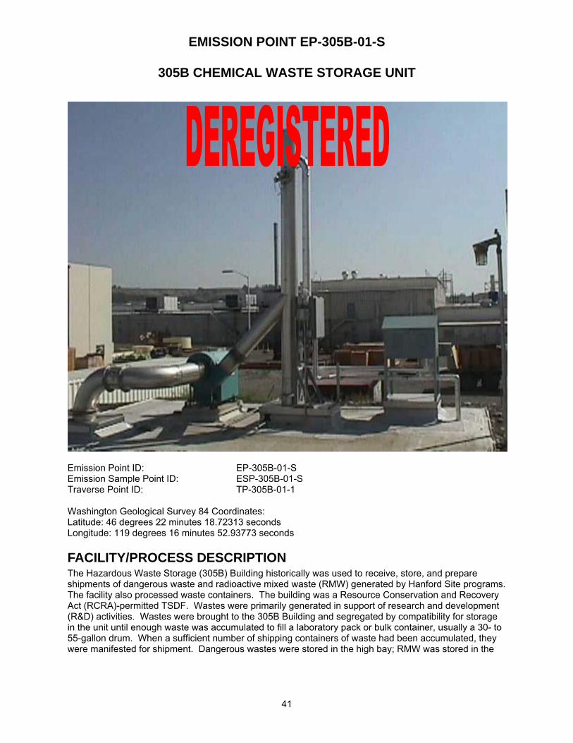
EMISSION POINT EP-305B-01-S
305B CHEMICAL WASTE STORAGE UNIT
41
Emission Point ID: EP-305B-01-S Emission Sample Point ID: ESP-305B-01-S Traverse Point ID: TP-305B-01-1 Washington Geological Survey 84 Coordinates: Latitude: 46 degrees 22 minutes 18.72313 seconds Longitude: 119 degrees 16 minutes 52.93773 seconds
FACILITY/PROCESS DESCRIPTION The Hazardous Waste Storage (305B) Building historically was used to receive, store, and prepare shipments of dangerous waste and radioactive mixed waste (RMW) generated by Hanford Site programs. The facility also processed waste containers. The building was a Resource Conservation and Recovery Act (RCRA)-permitted TSDF. Wastes were primarily generated in support of research and development (R&D) activities. Wastes were brought to the 305B Building and segregated by compatibility for storage in the unit until enough waste was accumulated to fill a laboratory pack or bulk container, usually a 30- to 55-gallon drum. When a sufficient number of shipping containers of waste had been accumulated, they were manifested for shipment. Dangerous wastes were stored in the high bay; RMW was stored in the
42
basement of the original wing of the building in the past. At present, no radiological waste is being stored or processed.
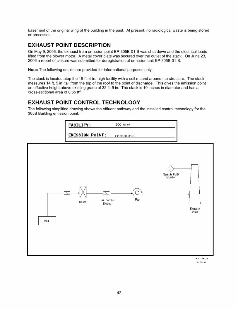
EXHAUST POINT DESCRIPTION On May 9, 2006, the exhaust from emission point EP-305B-01-S was shut down and the electrical leads lifted from the blower motor. A metal cover plate was secured over the outlet of the stack. On June 23, 2006 a report of closure was submitted for deregistration of emission unit EP-305B-01-S. Note: The following details are provided for informational purposes only. The stack is located atop the 18-ft, 4-in.-high facility with a soil mound around the structure. The stack measures 14 ft, 5 in. tall from the top of the roof to the point of discharge. This gives the emission point an effective height above existing grade of 32 ft, 9 in. The stack is 10 inches in diameter and has a cross-sectional area of 0.55 ft2.
EXHAUST POINT CONTROL TECHNOLOGY The following simplified drawing shows the effluent pathway and the installed control technology for the 305B Building emission point:
43
EXHAUST POINT FLOW RATE Exhaust flow rates were determined annually using EM procedure EMS-AIR-016. This procedure was developed based on the requirements in EPA 40 CFR 60, Appendix A, Method 2. The following table provides historical flow rate measurements:
Date Measured Flow Rate (CFM)05/27/98 1,037
05/12/99 1,102
05/04/00 963
06/13/02 919
06/25/02 1103
5/15/03 1084
6/24/04 960 6/21/05 820
Average ± 10% 1000 ± 100
Note: Flow measurements were canceled from the annual frequency in the calendar year 2006.
RECORD PARTICULATE SAMPLE SYSTEM DESCRIPTION The record particulate sampling system for emission point EP-305B-01-S was operated in conformance with 40 CFR 61, Subpart H and ANSI N13.1 (1969) requirements. See Stack Sampler Configuration Drawing H-3-307239.
SAMPLE EXTRACTION POINT The sample was extracted from the stack about 12 ft, 9 in. above the stack base. The sample probe is positioned 7 ft, 4 in. (8.8 equivalent diameters) downstream of the nearest flow disturbance and 1 ft, 8 in. (2.0 equivalent diameters) from the top of the stack.
SAMPLE EXTRACTION PROBE A stainless steel, two-nozzle probe manufactured by Air Monitor Corporation was used to extract the sample. Each nozzle inlet has a 0.404-in. ID. See the following vendor-supplied drawings for details: W27161AA, W27161AC, W27161AD, and W27161AE.
SAMPLE TRANSPORT LINE The sample transport line is constructed of 1.12-in. I.D. stainless steel tubing. The line makes a single 90º, 6.77-in. radius of curvature bend downward upon exiting the stack and terminates in a cabinet containing the collection filter, rotameter, and sample flow rate adjustment valve. The sample line upstream of the collector was insulated, heat traced, and electrically grounded. The sample line temperature was maintained above that of the stack gas to prevent condensation from forming in the sample line.
VACUUM AIR SAMPLE SYSTEM Vacuum was supplied to the sample system by a single Rietschle carbon vane pump enclosed in a weatherproof housing for protection against the elements.
44
This page is provided as a placeholder for the following drawings referenced for EP-305B-01-S: BATTELLE DRAWINGS NUMBER Stack Sampler Configuration EP-305B-01-S; Rev. 1 H-3-307239 The above drawing is not currently available to view electronically via this website. Electronic access to these drawings is available via the AutoManager® Software Program. Contact Shanna Abbott for AutoManager® access.
AIR MONITOR CORP. VENDOR DRAWINGS NUMBER Iso-Sampling Threaded Nozzle; Rev. 1 W27161AA Sample Probe Top Assembly; Rev. 1 W27161AC Mounting Plate, Fitting and End Plug; Rev. 1 W27161AD Iso-Sampling Manifold; Rev. 1 W27161AE Other drawings are provided by the vendor and are not available electronically at this time. For copies or questions regarding the drawings, contact Cheryl Duchsherer at 373-0594.
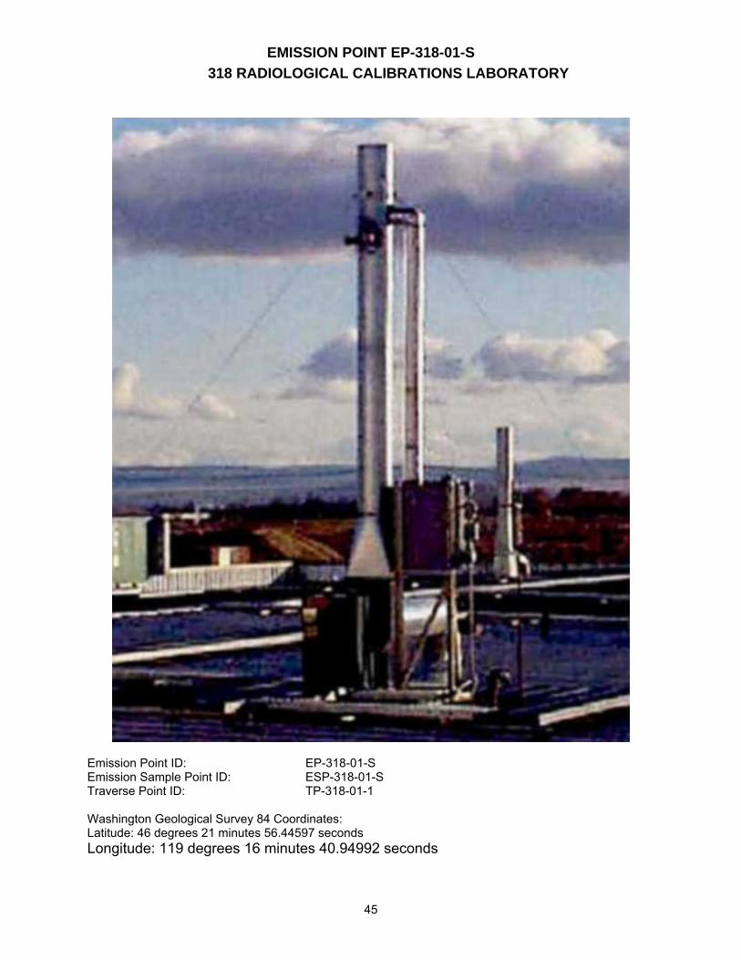
EMISSION POINT EP-318-01-S 318 RADIOLOGICAL CALIBRATIONS LABORATORY
45
Emission Point ID: EP-318-01-S Emission Sample Point ID: ESP-318-01-S Traverse Point ID: TP-318-01-1 Washington Geological Survey 84 Coordinates: Latitude: 46 degrees 21 minutes 56.44597 seconds Longitude: 119 degrees 16 minutes 40.94992 seconds
46
FACILITY/PROCESS DESCRIPTION The 318 Building is primarily used to provide 1) technical services in internal and external dosimetry, 2) instrument calibration, repair, and testing for protecting the health of workers and the public, and 3) liability protection for government and industrial customers. Research in the building includes developing radiation detection and measuring instruments.
EXHAUST POINT DESCRIPTION This stack was constructed to discharge air from a fume hood in Room 126 along with the exhaust from the vacuum air sample system. The stack is located on the roof of the 318 Building and measures 14 ft, 0.5 in. tall from the top of the roof to the point of discharge. This gives the emission point an effective height above the existing grade of 28 ft, 10.5 in. The stack is 10 inches in diameter and has a cross-sectional area of 0.55 ft2. The current system adopted the old emission point number EP-318-01-S and began operation on January 30, 1998. The old main stack exhaust flow was terminated on February 4, 1998, and the stack and sampling systems were abandoned in place. Information on the old system is documented on Stack Sampler Configuration Drawing H-3-307241 and is maintained for historical purposes.
47
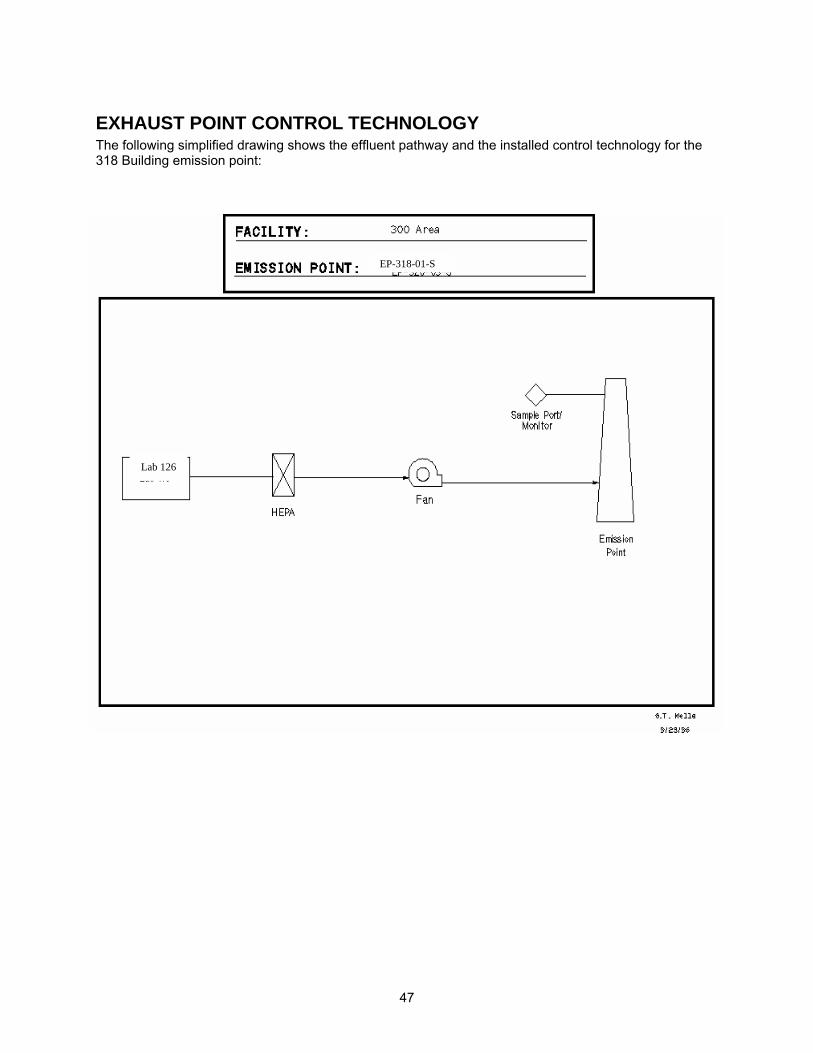
EXHAUST POINT CONTROL TECHNOLOGY The following simplified drawing shows the effluent pathway and the installed control technology for the 318 Building emission point:
Lab 126
EP-318-01-S
48
EXHAUST POINT FLOW RATE Exhaust flow rates are determined annually using EM procedure EMS-AIR-016. This procedure was developed based on the requirements in EPA 40 CFR 60, Appendix A, Method 2. The following table provides historical flow rate measurements:
Date Measured Flow Rate (CFM)05/12/98 502
04/28/99 481
04/20/00 480 06/14/01 413 06/25/02 484 07/29/03 484 06/24/04 583 06/21/05 616
Average ± 10% 500 ± 50
RECORD PARTICULATE SAMPLE SYSTEM DESCRIPTION The record particulate sampling system for emission point EP-318-01-S is operated in conformance with 40 CFR 61, Subpart H and ANSI N13.1 (1969) requirements. See Stack Sampler Configuration Drawing # H-3-307824.
SAMPLE EXTRACTION POINT The sample is extracted from the stack about 12 ft, 3.5 in. above the existing roof top at the stack base. The sample probe is positioned 7 ft, 3.5 in. (8.75 equivalent diameters) downstream of the nearest flow disturbance and 1 ft, 9 in. (2.1 equivalent diameters) from the top of the stack.
SAMPLE EXTRACTION PROBE A stainless steel, two-nozzle probe manufactured by Air Monitor Corporation is used to extract the sample. Each nozzle inlet has a 0.404-in. ID. The two sample nozzles are tapered and feed into a common 1.12-in.-ID manifold that is run on a horizontal plane across the stack. The manifold extends outside the stack 0.75 in. before making a 90º, 6-in. radius of curvature bend downward and uniting with the sample transport line. See vendor-supplied drawings for details: W32208AA, W32208BA, W32208BB, W32208BC, W32208BD, and W32208BE.
SAMPLE TRANSPORT LINE The sample transport line is constructed of 1.12-in. ID stainless steel tubing. The line extends downward and terminates in a cabinet containing the collection filter, rotameter, and sample flow rate adjustment valve. The sample line upstream of the collector is insulated, heat traced, and electrically grounded. The sample line temperature is maintained above that of the stack gas to prevent condensation from forming in the sample line.
VACUUM AIR SAMPLE SYSTEM Vacuum is supplied to the sample system by a single Rietschle carbon vane pump located in the basement equipment room. This system is powered by normal and emergency power.
49
BATTELLE DRAWINGS NUMBER Stack Sampler Configuration EP-318-01-S; Rev. 0 H-3-307241 Stack Sampler Configuration EP-318-01-S; Rev. 1 H-3-307824 HEPA Filter Installation Plan, Section and Notes; Rev. 0 H-3-309863 The above drawings are not currently available to view electronically via this website. Electronic access to these drawings is available via the AutoManager® Software Program. Contact Shanna Abbott for AutoManager® access. AIR MONITOR CORP. DRAWINGS NUMBER Flo-Sampler General Arrangement #1; Rev. 1 W32208AA Sample Probe Top Assembly; Rev. 0 W32208BA Iso-Sampling Threaded Nozzle; Rev. 0 W32208BB Iso-Sampling Manifold; Rev. 0 W32208BC Iso-Sampling Manifold; Rev. 0 W32208BD Mounting Plate, Fitting and End Plug; Rev. 0 W32208BE Other drawings are provided by the vendor and are not available electronically at this time. For copies or questions regarding the drawings, contact Cheryl Duchsherer at 373-0594.
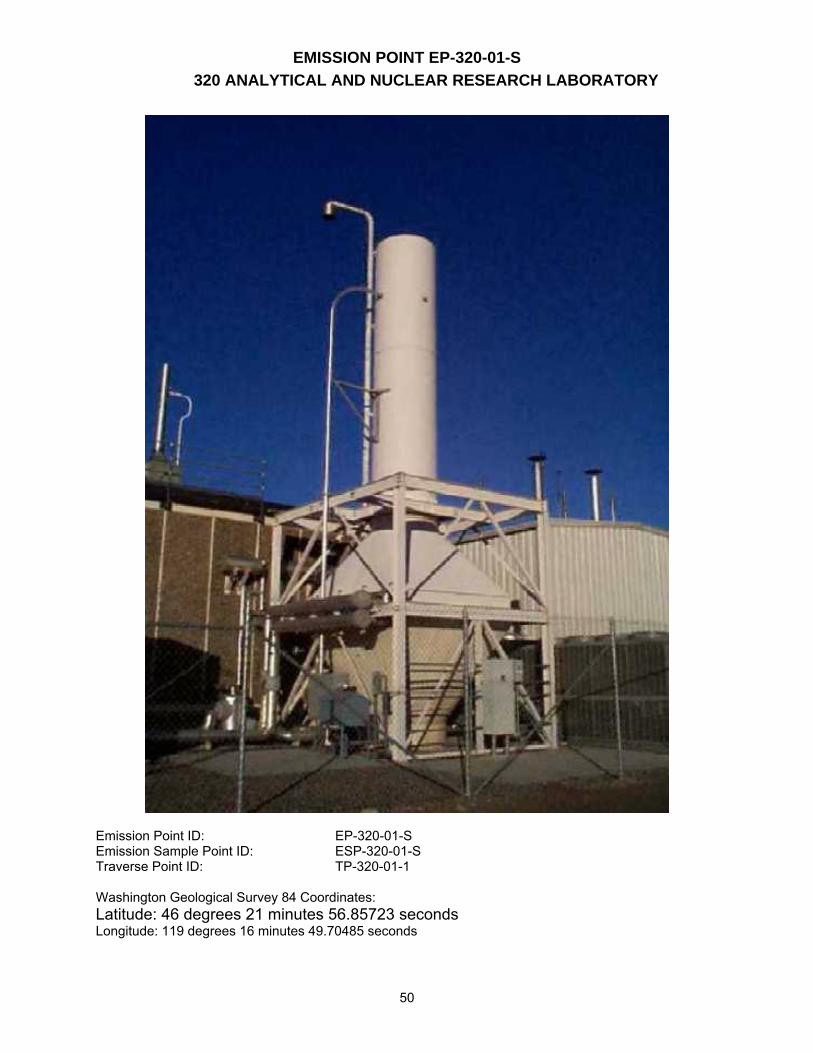
EMISSION POINT EP-320-01-S 320 ANALYTICAL AND NUCLEAR RESEARCH LABORATORY
50
Emission Point ID: EP-320-01-S Emission Sample Point ID: ESP-320-01-S Traverse Point ID: TP-320-01-1 Washington Geological Survey 84 Coordinates: Latitude: 46 degrees 21 minutes 56.85723 seconds Longitude: 119 degrees 16 minutes 49.70485 seconds
51
FACILITY/PROCESS DESCRIPTION Research activities conducted in the 320 Building involve special-purpose separation and analytical chemistry techniques that allow measurement of low-level and ultra-trace levels of material in environmental samples. Working with samples containing low/trace levels requires special building features, such as a clean zone. A class 10,000 clean zone allows for contamination-free preparation and analysis of samples containing extremely low levels of indicator radionuclides and trace organic compounds. Special instrumentation that is used for sample analysis includes various mass spectrometers, electron-beam microscopes, X-ray diffraction, and radiation counters.
EXHAUST POINT DESCRIPTION EP-320-01-S exhausts air from areas where radionuclides are handled. The stack is located on the south side of the facility. The stack measures 39 ft, 8 in. tall from the existing grade at the base of the stack to the point of discharge. The stack is 5 ft in diameter and has a cross-sectional area of 19.6 ft2.
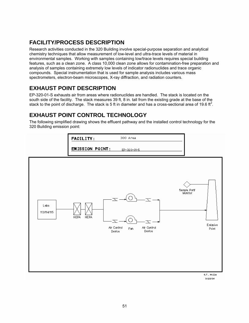
EXHAUST POINT CONTROL TECHNOLOGY The following simplified drawing shows the effluent pathway and the installed control technology for the 320 Building emission point:
52
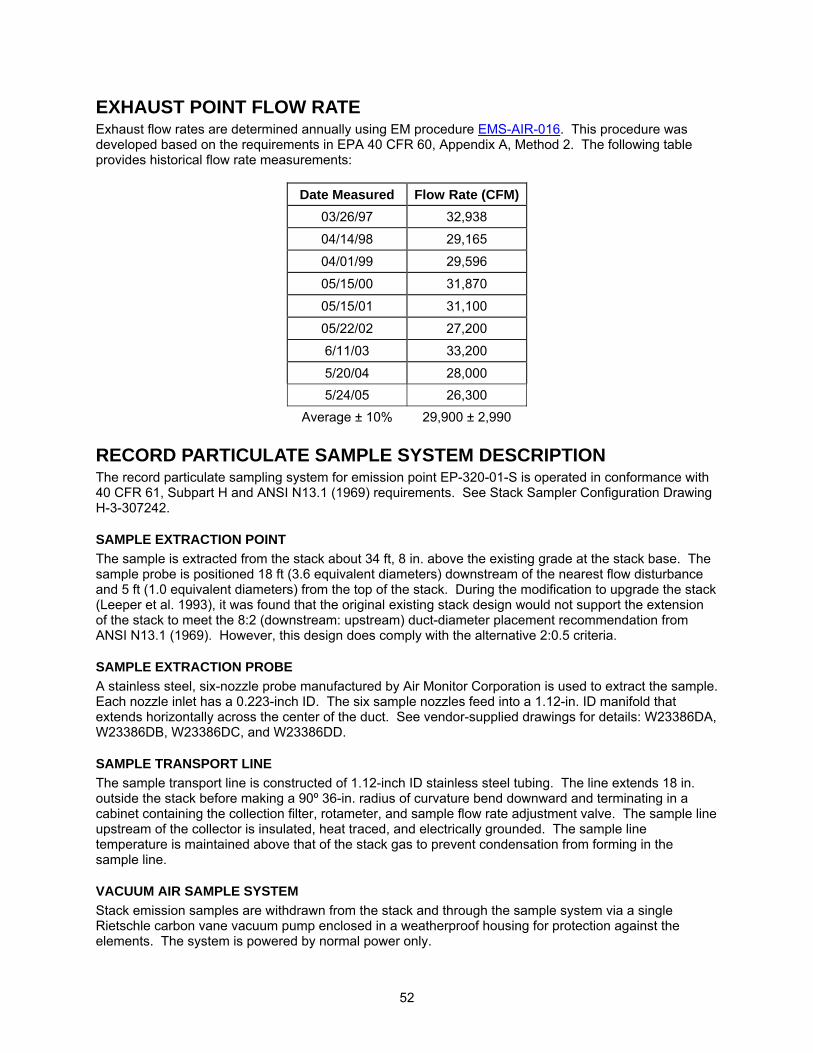
EXHAUST POINT FLOW RATE Exhaust flow rates are determined annually using EM procedure EMS-AIR-016. This procedure was developed based on the requirements in EPA 40 CFR 60, Appendix A, Method 2. The following table provides historical flow rate measurements:
Date Measured Flow Rate (CFM)03/26/97 32,938
04/14/98 29,165
04/01/99 29,596
05/15/00 31,870
05/15/01 31,100
05/22/02 27,200
6/11/03 33,200
5/20/04 28,000 5/24/05 26,300
Average ± 10% 29,900 ± 2,990
RECORD PARTICULATE SAMPLE SYSTEM DESCRIPTION The record particulate sampling system for emission point EP-320-01-S is operated in conformance with 40 CFR 61, Subpart H and ANSI N13.1 (1969) requirements. See Stack Sampler Configuration Drawing H-3-307242.
SAMPLE EXTRACTION POINT The sample is extracted from the stack about 34 ft, 8 in. above the existing grade at the stack base. The sample probe is positioned 18 ft (3.6 equivalent diameters) downstream of the nearest flow disturbance and 5 ft (1.0 equivalent diameters) from the top of the stack. During the modification to upgrade the stack (Leeper et al. 1993), it was found that the original existing stack design would not support the extension of the stack to meet the 8:2 (downstream: upstream) duct-diameter placement recommendation from ANSI N13.1 (1969). However, this design does comply with the alternative 2:0.5 criteria.
SAMPLE EXTRACTION PROBE A stainless steel, six-nozzle probe manufactured by Air Monitor Corporation is used to extract the sample. Each nozzle inlet has a 0.223-inch ID. The six sample nozzles feed into a 1.12-in. ID manifold that extends horizontally across the center of the duct. See vendor-supplied drawings for details: W23386DA, W23386DB, W23386DC, and W23386DD.
SAMPLE TRANSPORT LINE The sample transport line is constructed of 1.12-inch ID stainless steel tubing. The line extends 18 in. outside the stack before making a 90º 36-in. radius of curvature bend downward and terminating in a cabinet containing the collection filter, rotameter, and sample flow rate adjustment valve. The sample line upstream of the collector is insulated, heat traced, and electrically grounded. The sample line temperature is maintained above that of the stack gas to prevent condensation from forming in the sample line.
VACUUM AIR SAMPLE SYSTEM Stack emission samples are withdrawn from the stack and through the sample system via a single Rietschle carbon vane vacuum pump enclosed in a weatherproof housing for protection against the elements. The system is powered by normal power only.
53
BATTELLE DRAWINGS NUMBER Stack Sampler Configuration EP-320-01-S; Rev. 0 H-3-307242 The above drawing is not currently available to view electronically via this website. Electronic access to these drawings is available via the AutoManager® Software Program. Contact Shanna Abbott for AutoManager® access. AIR MONITOR CORP. DRAWINGS NUMBER #320 Isokinetic Sampling Probe; Rev. 2 W23386DA Iso-Sampling Threaded Nozzle; Rev. 0 W23386DB #320 Isokinetic Sampling Manifold; Rev. 0 W23386DC #320 Iso-Sampling Probe Plate, Plug and Fitting; Rev. 1 W23386DD Other drawings are provided by the vendor and are not available electronically at this time. For copies or questions regarding the drawings, contact Cheryl Duchsherer at 373-0594.
EMISSION POINT EP-320-02-S 320 ANALYTICAL AND NUCLEAR RESEARCH LABORATORY
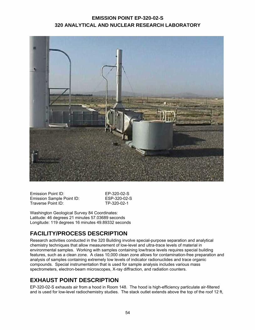
54
Emission Point ID: EP-320-02-S Emission Sample Point ID: ESP-320-02-S Traverse Point ID: TP-320-02-1 Washington Geological Survey 84 Coordinates: Latitude: 46 degrees 21 minutes 57.03689 seconds Longitude: 119 degrees 16 minutes 49.89332 seconds
FACILITY/PROCESS DESCRIPTION Research activities conducted in the 320 Building involve special-purpose separation and analytical chemistry techniques that allow measurement of low-level and ultra-trace levels of material in environmental samples. Working with samples containing low/trace levels requires special building features, such as a clean zone. A class 10,000 clean zone allows for contamination-free preparation and analysis of samples containing extremely low levels of indicator radionuclides and trace organic compounds. Special instrumentation that is used for sample analysis includes various mass spectrometers, electron-beam microscopes, X-ray diffraction, and radiation counters.
EXHAUST POINT DESCRIPTION EP-320-02-S exhausts air from a hood in Room 148. The hood is high-efficiency particulate air-filtered and is used for low-level radiochemistry studies. The stack outlet extends above the top of the roof 12 ft,
55
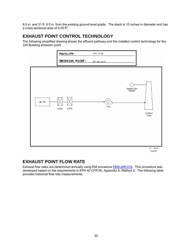
9.5 in. and 31 ft, 9.5 in. from the existing ground-level grade. The stack is 10 inches in diameter and has a cross-sectional area of 0.55 ft2. EXHAUST POINT CONTROL TECHNOLOGY The following simplified drawing shows the effluent pathway and the installed control technology for the 320 Building emission point:
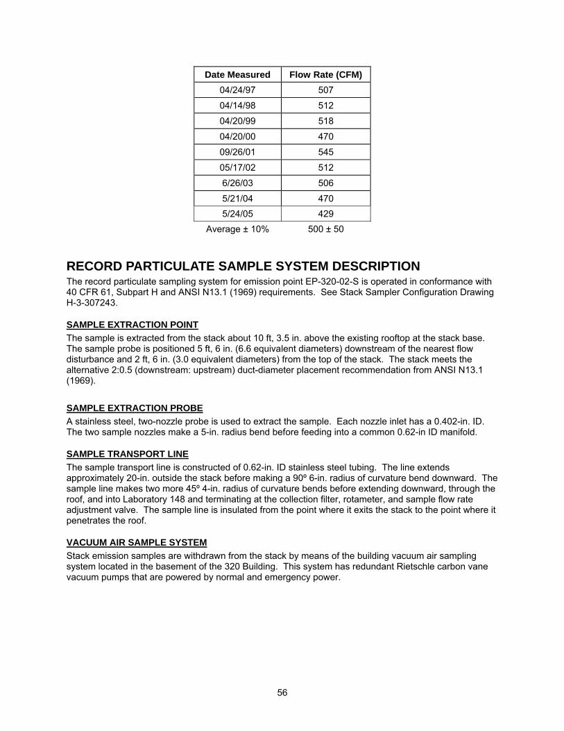
EXHAUST POINT FLOW RATE Exhaust flow rates are determined annually using EM procedure EMS-AIR-016. This procedure was developed based on the requirements in EPA 40 CFR 60, Appendix A, Method 2. The following table provides historical flow rate measurements:
56
Date Measured Flow Rate (CFM) 04/24/97 507
04/14/98 512
04/20/99 518
04/20/00 470
09/26/01 545
05/17/02 512
6/26/03 506
5/21/04 470 5/24/05 429
Average ± 10% 500 ± 50
RECORD PARTICULATE SAMPLE SYSTEM DESCRIPTION The record particulate sampling system for emission point EP-320-02-S is operated in conformance with 40 CFR 61, Subpart H and ANSI N13.1 (1969) requirements. See Stack Sampler Configuration Drawing H-3-307243.
SAMPLE EXTRACTION POINT The sample is extracted from the stack about 10 ft, 3.5 in. above the existing rooftop at the stack base. The sample probe is positioned 5 ft, 6 in. (6.6 equivalent diameters) downstream of the nearest flow disturbance and 2 ft, 6 in. (3.0 equivalent diameters) from the top of the stack. The stack meets the alternative 2:0.5 (downstream: upstream) duct-diameter placement recommendation from ANSI N13.1 (1969).
SAMPLE EXTRACTION PROBE A stainless steel, two-nozzle probe is used to extract the sample. Each nozzle inlet has a 0.402-in. ID. The two sample nozzles make a 5-in. radius bend before feeding into a common 0.62-in ID manifold.
SAMPLE TRANSPORT LINE The sample transport line is constructed of 0.62-in. ID stainless steel tubing. The line extends approximately 20-in. outside the stack before making a 90º 6-in. radius of curvature bend downward. The sample line makes two more 45º 4-in. radius of curvature bends before extending downward, through the roof, and into Laboratory 148 and terminating at the collection filter, rotameter, and sample flow rate adjustment valve. The sample line is insulated from the point where it exits the stack to the point where it penetrates the roof.
VACUUM AIR SAMPLE SYSTEM Stack emission samples are withdrawn from the stack by means of the building vacuum air sampling system located in the basement of the 320 Building. This system has redundant Rietschle carbon vane vacuum pumps that are powered by normal and emergency power.

57
BATTELLE DRAWINGS NUMBER Stack Sampler Configuration EP-320-02-S; Rev. 0 H-3-307243 The above drawing is not currently available to view electronically via this website. Electronic access to these drawings is available via the AutoManager® Software Program. Contact Shanna Abbott for AutoManager® access.
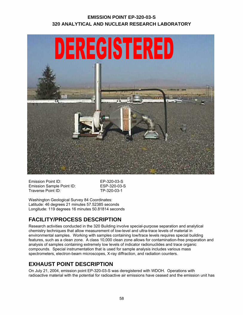
EMISSION POINT EP-320-03-S 320 ANALYTICAL AND NUCLEAR RESEARCH LABORATORY
58
Emission Point ID: EP-320-03-S Emission Sample Point ID: ESP-320-03-S Traverse Point ID: TP-320-03-1 Washington Geological Survey 84 Coordinates: Latitude: 46 degrees 21 minutes 57.52385 seconds Longitude: 119 degrees 16 minutes 50.81814 seconds
FACILITY/PROCESS DESCRIPTION Research activities conducted in the 320 Building involve special-purpose separation and analytical chemistry techniques that allow measurement of low-level and ultra-trace levels of material in environmental samples. Working with samples containing low/trace levels requires special building features, such as a clean zone. A class 10,000 clean zone allows for contamination-free preparation and analysis of samples containing extremely low levels of indicator radionuclides and trace organic compounds. Special instrumentation that is used for sample analysis includes various mass spectrometers, electron-beam microscopes, X-ray diffraction, and radiation counters.
EXHAUST POINT DESCRIPTION On July 21, 2004, emission point EP-320-03-S was deregistered with WDOH. Operations with radioactive material with the potential for radioactive air emissions have ceased and the emission unit has
59
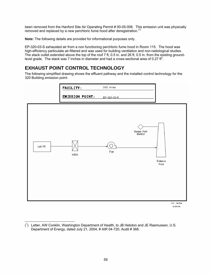
been removed from the Hanford Site Air Operating Permit # 00-05-006. This emission unit was physically removed and replaced by a new perchloric fume hood after deregistration.(1) Note: The following details are provided for informational purposes only. EP-320-03-S exhausted air from a non functioning perchloric fume hood in Room 115. The hood was high-efficiency particulate air-filtered and was used for building ventilation and non-radiological studies. The stack outlet extended above the top of the roof 7 ft, 0.5 in. and 26 ft, 0.5 in. from the existing ground-level grade. The stack was 7 inches in diameter and had a cross-sectional area of 0.27 ft2.
EXHAUST POINT CONTROL TECHNOLOGY The following simplified drawing shows the effluent pathway and the installed control technology for the 320 Building emission point:
(1) Letter, AW Conklin, Washington Department of Health, to JB Hebdon and JE Rasmussen, U.S.
Department of Energy, dated July 21, 2004, # AIR 04-720, Audit # 368.
60
EXHAUST POINT FLOW RATE Exhaust flow rates were determined annually using EM procedure EMS-AIR-016. This procedure was developed based on the requirements in EPA 40 CFR 60, Appendix A, Method 2. The following table provides historical flow rate measurements:
Date Measured Flow Rate (CFM)04/27/97 444
04/14/98 430
04/20/99 433
04/20/00 606
09/26/01 347
05/17/02 382
06/26/03 348 05/21/04 416
Average ± 10% 430 ± 43
Note: Flow measurements were canceled from the annual frequency in the calendar year 2004.
RECORD PARTICULATE SAMPLE SYSTEM DESCRIPTION The record particulate sampling system for emission point EP-320-03-S was operated in conformance with 40 CFR 61, Subpart H and ANSI N13.1 (1969) requirements. See Stack Sampler Configuration Drawing # H-3-307244.
SAMPLE EXTRACTION POINT The sample was extracted from the stack about 4 ft, 5.5 in. above the existing rooftop at the stack base. The sample probe is positioned 1 ft, 10.5 in. (3.2 equivalent diameters) downstream of the nearest flow disturbance and 2 ft, 7 in. (4.4 equivalent diameters) from the top of the stack. The stack meets the alternative 2:0.5 (downstream: upstream) duct-diameter placement recommendation from ANSI N13.1 (1969).
SAMPLE EXTRACTION PROBE A stainless steel, one-nozzle probe was used to extract the sample. The nozzle inlet has a 0.402-in. ID. The sample nozzle makes a 1.5-in. radius bend, and the sample tubing extends outside the stack wall 3 in. before expanding to the sample transport line ID.
SAMPLE TRANSPORT LINE The sample transport line is constructed of 0.62-in. ID stainless steel tubing. The line extends approximately 5 ft, 7.75 in. from the tubing expansion and then makes a 90º 7.75-in. radius of curvature bend downward. The sample line extends downward through the roof and into Laboratory 115 and terminates at the collection filter, rotameter, and sample flow rate adjustment valve. The sample line is insulated from the point where it exits the stack to the point where it penetrates the roof.
VACUUM AIR SAMPLE SYSTEM Stack emission samples were withdrawn from the stack by means of the building vacuum air sampling system located in the basement of the 320 Building. This system has redundant Rietschle carbon vane vacuum pumps that are powered by normal and emergency power.
61
BATTELLE DRAWINGS NUMBER Stack Sampler Configuration EP-320-03-S; Rev. 0 H-3-307244 The above drawing is not currently available to view electronically via this website. Electronic access to these drawings is available via the AutoManager® Software Program. Contact Shanna Abbott for AutoManager® access.
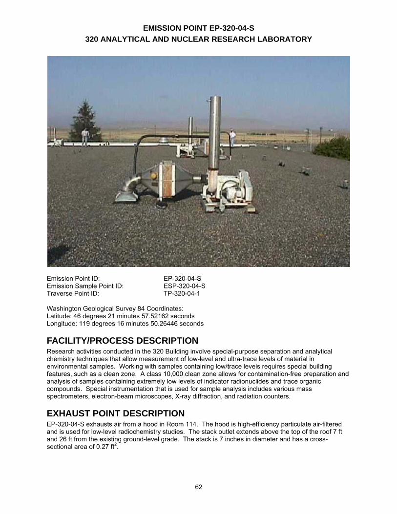
EMISSION POINT EP-320-04-S 320 ANALYTICAL AND NUCLEAR RESEARCH LABORATORY
62
Emission Point ID: EP-320-04-S Emission Sample Point ID: ESP-320-04-S Traverse Point ID: TP-320-04-1 Washington Geological Survey 84 Coordinates: Latitude: 46 degrees 21 minutes 57.52162 seconds Longitude: 119 degrees 16 minutes 50.26446 seconds
FACILITY/PROCESS DESCRIPTION Research activities conducted in the 320 Building involve special-purpose separation and analytical chemistry techniques that allow measurement of low-level and ultra-trace levels of material in environmental samples. Working with samples containing low/trace levels requires special building features, such as a clean zone. A class 10,000 clean zone allows for contamination-free preparation and analysis of samples containing extremely low levels of indicator radionuclides and trace organic compounds. Special instrumentation that is used for sample analysis includes various mass spectrometers, electron-beam microscopes, X-ray diffraction, and radiation counters.
EXHAUST POINT DESCRIPTION EP-320-04-S exhausts air from a hood in Room 114. The hood is high-efficiency particulate air-filtered and is used for low-level radiochemistry studies. The stack outlet extends above the top of the roof 7 ft and 26 ft from the existing ground-level grade. The stack is 7 inches in diameter and has a cross-sectional area of 0.27 ft2.
63
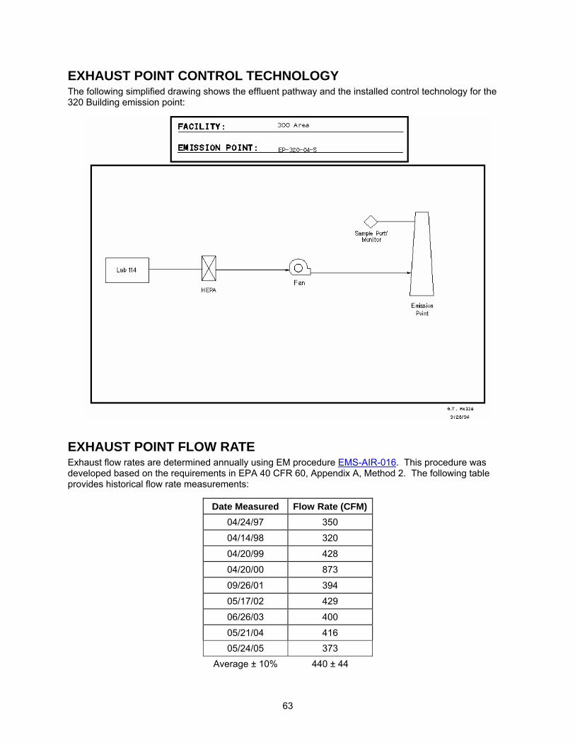
EXHAUST POINT CONTROL TECHNOLOGY The following simplified drawing shows the effluent pathway and the installed control technology for the 320 Building emission point:
EXHAUST POINT FLOW RATE Exhaust flow rates are determined annually using EM procedure EMS-AIR-016. This procedure was developed based on the requirements in EPA 40 CFR 60, Appendix A, Method 2. The following table provides historical flow rate measurements:
Date Measured Flow Rate (CFM)04/24/97 350
04/14/98 320
04/20/99 428
04/20/00 873
09/26/01 394
05/17/02 429
06/26/03 400
05/21/04 416 05/24/05 373
Average ± 10% 440 ± 44
64
RECORD PARTICULATE SAMPLE SYSTEM DESCRIPTION The record particulate sampling system for emission point EP-320-04-S is operated in conformance with 40 CFR 61, Subpart H and ANSI N13.1 (1969) requirements. See Stack Sampler Configuration Drawing # H-3-307245.
SAMPLE EXTRACTION POINT The sample is extracted from the stack about 4 ft, 5.6 in. above the existing rooftop at the stack base. The sample probe is positioned 2 ft (3.4 equivalent diameters) downstream of the nearest flow disturbance and 3 ft, 6.38 in. (6.1 equivalent diameters) from the top of the stack. The stack meets the alternative 2:0.5 (downstream: upstream) duct-diameter placement recommendation from ANSI N13.1 (1969).
SAMPLE EXTRACTION PROBE A stainless steel, one-nozzle probe is used to extract the sample. The nozzle inlet has a 0.402-in. ID. The sample nozzle makes a 1.5-in. radius bend, and the sample tubing extends outside the stack wall 3-in. before expanding to the sample transport line ID.
SAMPLE TRANSPORT LINE The sample transport line is constructed of 0.62-in. ID stainless steel tubing. The line extends approximately 4 ft, 6 in. from the tubing expansion and then makes a 90º 13-in. radius of curvature bend downward. The sample line extends downward through the roof and into Laboratory 114 and terminates at the collection filter, rotameter, and sample flow rate adjustment valve. The sample line is insulated from the point where it exits the stack to the point where it penetrates the roof.
VACUUM AIR SAMPLE SYSTEM Stack emission samples are withdrawn from the stack by means of the building vacuum air sampling system located in the basement of the 320 Building. This system has redundant Rietschle carbon vane vacuum pumps that are powered by normal and emergency power.

65
BATTELLE DRAWINGS NUMBER Stack Sampler Configuration EP-320-04-S; Rev. 0 H-3-307245 The above drawing is not currently available to view electronically via this website. Electronic access to these drawings is available via the AutoManager® Software Program. Contact Shanna Abbott for AutoManager® access.
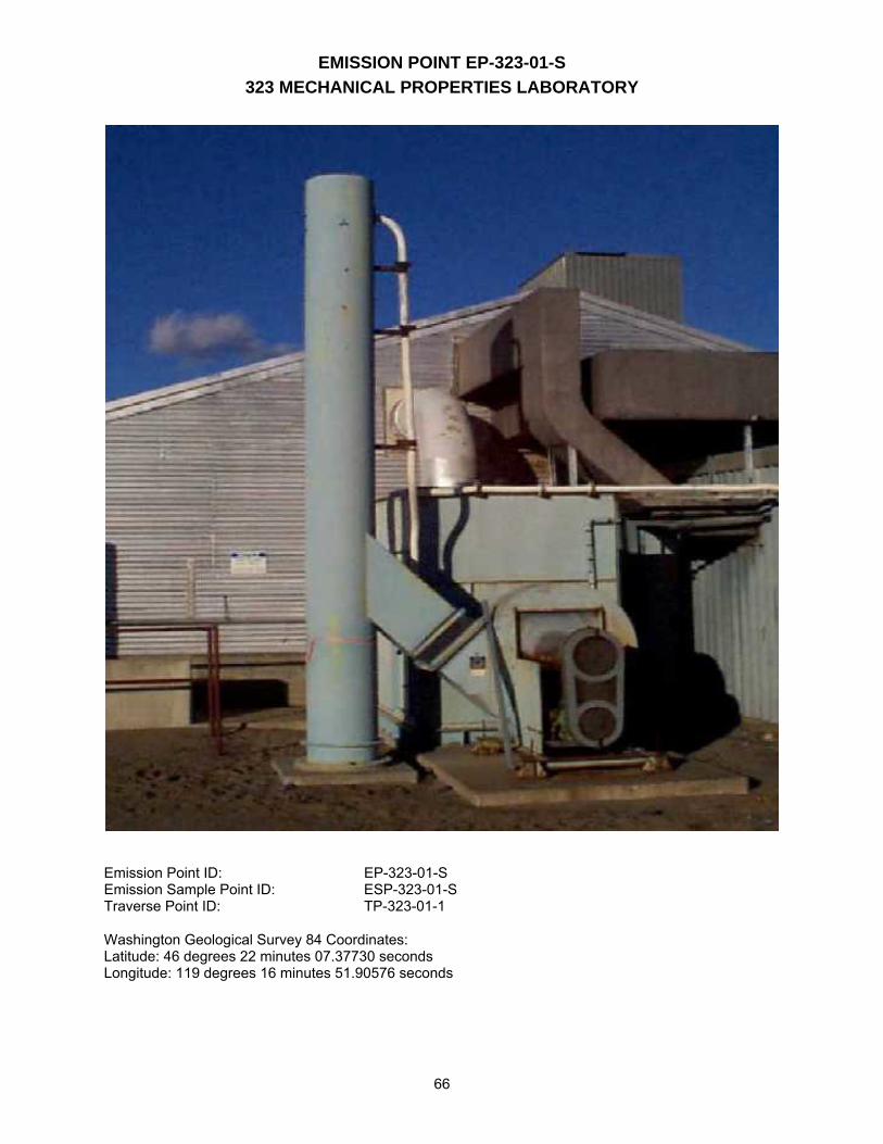
EMISSION POINT EP-323-01-S 323 MECHANICAL PROPERTIES LABORATORY
66
Emission Point ID: EP-323-01-S Emission Sample Point ID: ESP-323-01-S Traverse Point ID: TP-323-01-1 Washington Geological Survey 84 Coordinates: Latitude: 46 degrees 22 minutes 07.37730 seconds Longitude: 119 degrees 16 minutes 51.90576 seconds
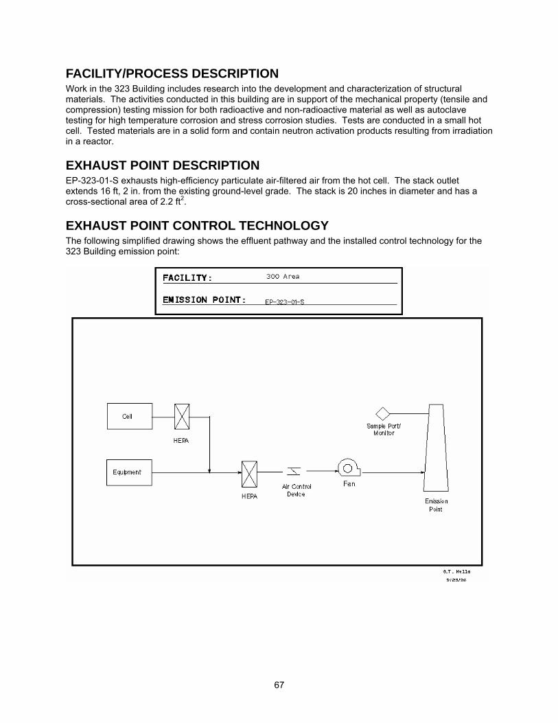
67
FACILITY/PROCESS DESCRIPTION Work in the 323 Building includes research into the development and characterization of structural materials. The activities conducted in this building are in support of the mechanical property (tensile and compression) testing mission for both radioactive and non-radioactive material as well as autoclave testing for high temperature corrosion and stress corrosion studies. Tests are conducted in a small hot cell. Tested materials are in a solid form and contain neutron activation products resulting from irradiation in a reactor.
EXHAUST POINT DESCRIPTION EP-323-01-S exhausts high-efficiency particulate air-filtered air from the hot cell. The stack outlet extends 16 ft, 2 in. from the existing ground-level grade. The stack is 20 inches in diameter and has a cross-sectional area of 2.2 ft2.
EXHAUST POINT CONTROL TECHNOLOGY The following simplified drawing shows the effluent pathway and the installed control technology for the 323 Building emission point:
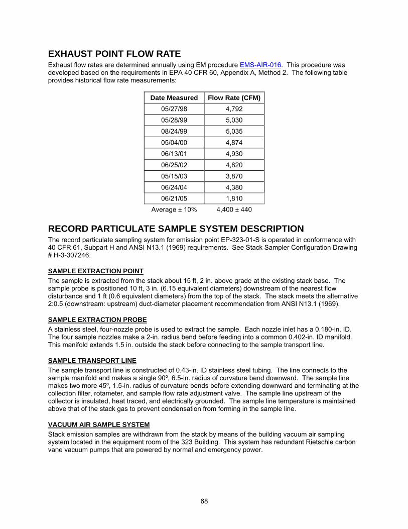
68
EXHAUST POINT FLOW RATE Exhaust flow rates are determined annually using EM procedure EMS-AIR-016. This procedure was developed based on the requirements in EPA 40 CFR 60, Appendix A, Method 2. The following table provides historical flow rate measurements:
Date Measured Flow Rate (CFM)05/27/98 4,792
05/28/99 5,030
08/24/99 5,035
05/04/00 4,874
06/13/01 4,930
06/25/02 4,820
05/15/03 3,870
06/24/04 4,380 06/21/05 1,810
Average ± 10% 4,400 ± 440
RECORD PARTICULATE SAMPLE SYSTEM DESCRIPTION The record particulate sampling system for emission point EP-323-01-S is operated in conformance with 40 CFR 61, Subpart H and ANSI N13.1 (1969) requirements. See Stack Sampler Configuration Drawing # H-3-307246.
SAMPLE EXTRACTION POINT The sample is extracted from the stack about 15 ft, 2 in. above grade at the existing stack base. The sample probe is positioned 10 ft, 3 in. (6.15 equivalent diameters) downstream of the nearest flow disturbance and 1 ft (0.6 equivalent diameters) from the top of the stack. The stack meets the alternative 2:0.5 (downstream: upstream) duct-diameter placement recommendation from ANSI N13.1 (1969).
SAMPLE EXTRACTION PROBE A stainless steel, four-nozzle probe is used to extract the sample. Each nozzle inlet has a 0.180-in. ID. The four sample nozzles make a 2-in. radius bend before feeding into a common 0.402-in. ID manifold. This manifold extends 1.5 in. outside the stack before connecting to the sample transport line.
SAMPLE TRANSPORT LINE The sample transport line is constructed of 0.43-in. ID stainless steel tubing. The line connects to the sample manifold and makes a single 90º, 6.5-in. radius of curvature bend downward. The sample line makes two more 45º, 1.5-in. radius of curvature bends before extending downward and terminating at the collection filter, rotameter, and sample flow rate adjustment valve. The sample line upstream of the collector is insulated, heat traced, and electrically grounded. The sample line temperature is maintained above that of the stack gas to prevent condensation from forming in the sample line.
VACUUM AIR SAMPLE SYSTEM Stack emission samples are withdrawn from the stack by means of the building vacuum air sampling system located in the equipment room of the 323 Building. This system has redundant Rietschle carbon vane vacuum pumps that are powered by normal and emergency power.

69
BATTELLE DRAWINGS NUMBER Stack Sampler Configuration EP-323-01-S; Rev. 0 H-3-307246 The above drawing is not currently available to view electronically via this website. Electronic access to these drawings is available via the AutoManager® Software Program. Contact Shanna Abbott for AutoManager® access.
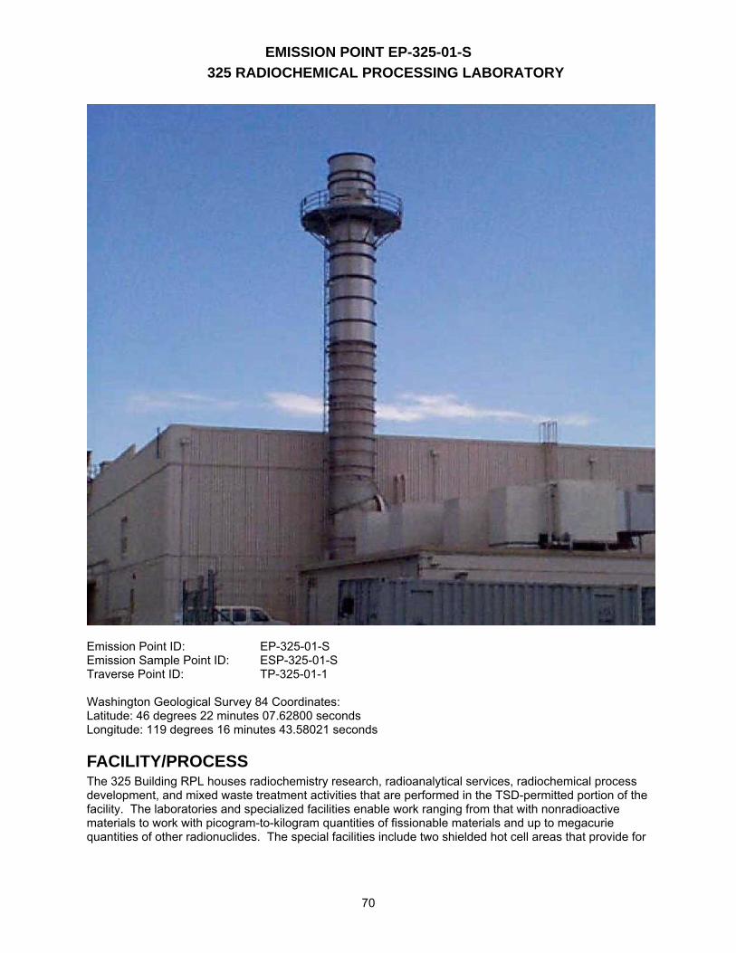
EMISSION POINT EP-325-01-S 325 RADIOCHEMICAL PROCESSING LABORATORY
70
Emission Point ID: EP-325-01-S Emission Sample Point ID: ESP-325-01-S Traverse Point ID: TP-325-01-1 Washington Geological Survey 84 Coordinates: Latitude: 46 degrees 22 minutes 07.62800 seconds Longitude: 119 degrees 16 minutes 43.58021 seconds
FACILITY/PROCESS The 325 Building RPL houses radiochemistry research, radioanalytical services, radiochemical process development, and mixed waste treatment activities that are performed in the TSD-permitted portion of the facility. The laboratories and specialized facilities enable work ranging from that with nonradioactive materials to work with picogram-to-kilogram quantities of fissionable materials and up to megacurie quantities of other radionuclides. The special facilities include two shielded hot cell areas that provide for
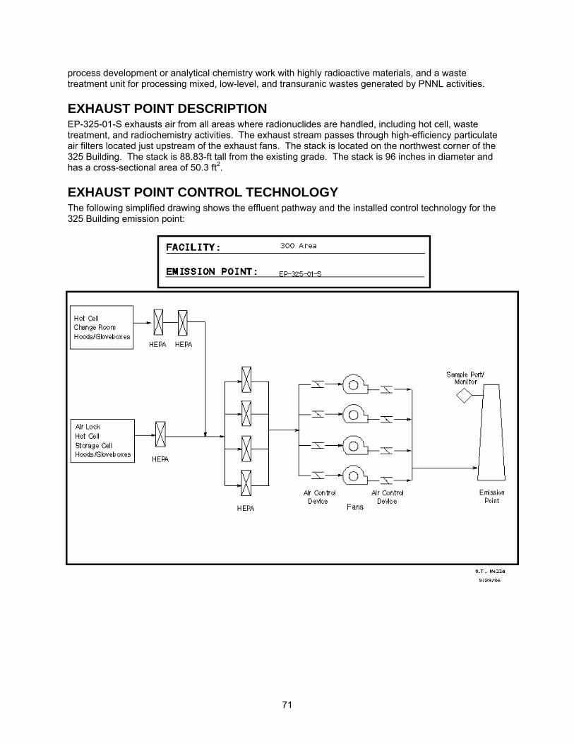
71
process development or analytical chemistry work with highly radioactive materials, and a waste treatment unit for processing mixed, low-level, and transuranic wastes generated by PNNL activities.
EXHAUST POINT DESCRIPTION EP-325-01-S exhausts air from all areas where radionuclides are handled, including hot cell, waste treatment, and radiochemistry activities. The exhaust stream passes through high-efficiency particulate air filters located just upstream of the exhaust fans. The stack is located on the northwest corner of the 325 Building. The stack is 88.83-ft tall from the existing grade. The stack is 96 inches in diameter and has a cross-sectional area of 50.3 ft2.
EXHAUST POINT CONTROL TECHNOLOGY The following simplified drawing shows the effluent pathway and the installed control technology for the 325 Building emission point:
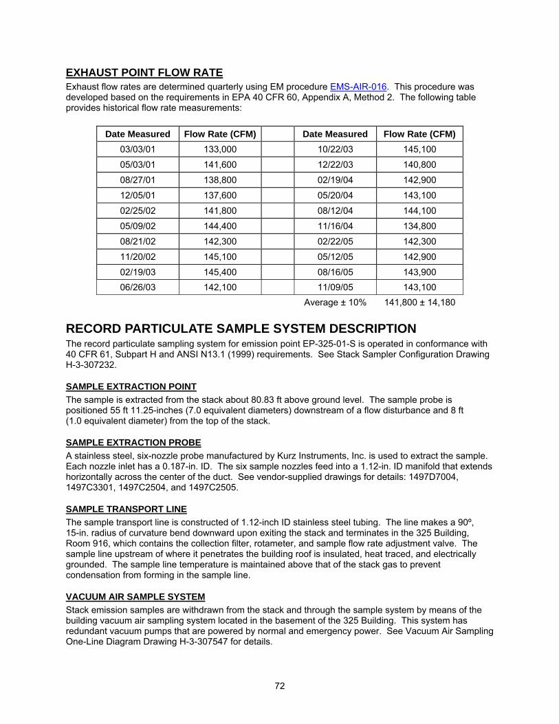
72
EXHAUST POINT FLOW RATE Exhaust flow rates are determined quarterly using EM procedure EMS-AIR-016. This procedure was developed based on the requirements in EPA 40 CFR 60, Appendix A, Method 2. The following table provides historical flow rate measurements:
Date Measured Flow Rate (CFM) Date Measured Flow Rate (CFM) 03/03/01 133,000 10/22/03 145,100
05/03/01 141,600 12/22/03 140,800
08/27/01 138,800 02/19/04 142,900
12/05/01 137,600 05/20/04 143,100
02/25/02 141,800 08/12/04 144,100
05/09/02 144,400 11/16/04 134,800
08/21/02 142,300 02/22/05 142,300
11/20/02 145,100 05/12/05 142,900
02/19/03 145,400 08/16/05 143,900 06/26/03 142,100 11/09/05 143,100
Average ± 10% 141,800 ± 14,180
RECORD PARTICULATE SAMPLE SYSTEM DESCRIPTION The record particulate sampling system for emission point EP-325-01-S is operated in conformance with 40 CFR 61, Subpart H and ANSI N13.1 (1999) requirements. See Stack Sampler Configuration Drawing H-3-307232.
SAMPLE EXTRACTION POINT The sample is extracted from the stack about 80.83 ft above ground level. The sample probe is positioned 55 ft 11.25-inches (7.0 equivalent diameters) downstream of a flow disturbance and 8 ft (1.0 equivalent diameter) from the top of the stack.
SAMPLE EXTRACTION PROBE A stainless steel, six-nozzle probe manufactured by Kurz Instruments, Inc. is used to extract the sample. Each nozzle inlet has a 0.187-in. ID. The six sample nozzles feed into a 1.12-in. ID manifold that extends horizontally across the center of the duct. See vendor-supplied drawings for details: 1497D7004, 1497C3301, 1497C2504, and 1497C2505.
SAMPLE TRANSPORT LINE The sample transport line is constructed of 1.12-inch ID stainless steel tubing. The line makes a 90º, 15-in. radius of curvature bend downward upon exiting the stack and terminates in the 325 Building, Room 916, which contains the collection filter, rotameter, and sample flow rate adjustment valve. The sample line upstream of where it penetrates the building roof is insulated, heat traced, and electrically grounded. The sample line temperature is maintained above that of the stack gas to prevent condensation from forming in the sample line.
VACUUM AIR SAMPLE SYSTEM Stack emission samples are withdrawn from the stack and through the sample system by means of the building vacuum air sampling system located in the basement of the 325 Building. This system has redundant vacuum pumps that are powered by normal and emergency power. See Vacuum Air Sampling One-Line Diagram Drawing H-3-307547 for details.
73
SAMPLE COLLECTION Particulate samples are collected using a 47-mm supported membrane filter (Gelman Sciences Versapor-Membrane, acrylic copolymer membrane filter) mounted in a modified sample holder. See drawings in Appendix C for details. The membrane filter has an estimated retention efficiency for 0.3-micron particles of greater than 91%. The sample flow rate is measured by a Brooks Instrument GT-1000 (0.586 to 5.86 scfm) rotameter and adjusted using a throttle valve (both located just downstream of the filter holder). A vacuum gauge (0 to 100 in. of water) is installed on the inlet side of the rotameter and used to correct the sample flow for vacuum conditions. Sampler flows are set at or near isokinetic based on stack flow measurements that are performed on a quarterly basis. A 2-week particulate sample is collected on a continuous basis to confirm that emissions are below the 0.1 mrem/yr offsite dose. The sample system is inspected each workday, excluding weekends and holidays, for proper flow rate settings and system operation. The rotameter and vacuum gauge are exchanged on an annual basis with calibrated spares. A Battelle-approved calibration laboratory performs calibration on these instruments.
TRITIUM SAMPLING SYSTEM DESCRIPTION Tritium as water vapor (HTO) and tritium gas (HT) is sampled continuously using a two-stage sampling system located in the 325 Building, Room 916. The sample is drawn downstream of the record particulate sampling system. See Stack Sampling/Monitoring System Flow Diagram Drawing H-3-70531.
TRITIUM SAMPLE EXTRACTION POINT The sample is extracted from the stack about 80.83 ft above ground level. The sample probe is positioned 55 ft 11.25-inches (7.0 equivalent diameters) downstream of a flow disturbance and 8 ft (1.0 equivalent diameter) from the top of the stack.
TRITIUM SAMPLE EXTRACTION PROBE A stainless steel, six-nozzle probe manufactured by Kurz Instruments, Inc. is used to extract the sample. Each nozzle inlet has a 0.187-in. ID. The six sample nozzles feed into a 1.12-in. ID manifold that extends horizontally across the center of the duct. See attached vendor-supplied drawings for details: 1497D7004, 1497C3301, 1497C2504, and 1497C2505.
TRITIUM SAMPLE TRANSPORT LINE The sample transport line is constructed of 1.12-in. ID stainless steel tubing. The line makes a 90º, 15-in. radius of curvature bend downward upon exiting the stack and terminates in the 325 Building, Room 916, which contains the record particulate collection filter, rotameter, and sample flow rate adjustment valve. The tritium sample train draws from this source just downstream from the record particulate sampling system (see drawing H-3-70531). The sample line upstream of where it penetrates the building roof is insulated, heat traced, and electrically grounded. The sample line temperature is maintained above that of the stack gas to prevent losses caused by condensation forming in the sample line.
VACUUM AIR SAMPLE SYSTEM Stack emission samples are withdrawn from the stack and through the system by means of the building vacuum air sampling system located in the basement of the 325 Building. This system has redundant vacuum pumps that are powered by normal and emergency power. See Vacuum Air Sampling One-Line Diagram Drawing H-3-307547 for details.
TRITIUM SAMPLE COLLECTION The record particulate sample collector acts as a prefilter for the tritium sample stream, and the flow is measured using a calibrated rotameter. The sub-sample flow rate to the tritium sampler is a nominal 200 mL/min.
74
Initially, the sample stream is mixed with a nitrogen-hydrogen carrier gas (3% H2 in N2). It then enters the first tritium collection unit where silica gel is used to strip water vapor from the gas stream. On exit from the first stage, the now dry sample stream is heated to >180°C in the presence of a palladium catalyst to convert free hydrogen (HT and TT) to water vapor. The sample stream is then cooled to under 40°C and passed through the second silica gel collector to strip out the water vapor generated from the catalytic oxidation of free hydrogen. Samples are collected over a 1-month period or until the silica gel cartridge loading sampling system meets or exceeds 2/3 loading (based on color change), whichever comes first. Following the sampling period, the samples are delivered to the analytical laboratory to determine the tritium content. The sample system is inspected each workday, excluding weekends and holidays, for proper flow rate settings and system operation. Thermocouples and associated digital temperature displays are either calibrated in place or replaced with calibrated spares on an annual basis. PNNL Maintenance Services performs these per group-specific procedures. Rotameters that measure sample and carrier gas flows are exchanged with calibrated spares on an annual basis. A Battelle-approved calibration laboratory performs calibration on these instruments. See Appendix B for analysis and data evaluation requirements for tritium samples collected from this major emission point.
STACK PARTICULATE MONITORING SYSTEM DESCRIPTION The 325 Stack Particulate CAM system for emission point EP-325-01-S is operated in conformance with 40 CFR 61, Subpart H and ANSI N13.1 (1969) requirements. See Stack Sampler Configuration Drawing H-3-307232. Stack air is continuously monitored for radioactivity associated with particulate matter by an EG&G-Berthold LB-150D alpha-beta-pseudocoincident monitor. The monitor uses an 8-in. diameter glass-fiber filter to collect airborne particles from the stack. The filter is mounted against a sandwich arrangement of gas-flow proportional radiation detectors to count the alpha, beta, and gamma emissions as particles accumulate on the filter. The monitoring system accounts for the presence of radioactive material associated with the decay products of naturally occurring radon isotopes by means of a timing gate to identify simultaneous alpha and beta emissions occurring on the filter. This method, referred to as the alpha-beta-pseudocoincidence-difference method, uses the nearly simultaneous (pseudocoincident) alpha-beta decay transitions in the 220Rn and 222Rn decay chains as a means of distinguishing naturally occurring radionuclides from artificial radionuclides deposited on the sample filter. Three gas-flow proportional counters in a sandwich configuration independently count the number of alpha, beta, and gamma emissions on the sample collection filter. In addition, alpha and beta emissions that are detected pseudocoincidentally are also counted. The number of pseudocoincident events times a scaling factor is subtracted from the total alpha and beta counts to yield the net event detections attributed to sources other than radon isotopes. Local and remote annunciators provide indications of high particulate radionuclide emissions as well as monitor component failures.
PARTICULATE MONITOR SAMPLE EXTRACTION POINT The sample is extracted from the stack about 80.83 ft above ground level. The sample probe is positioned 55 ft 11.25-inches (7.0 equivalent diameters) downstream of a flow disturbance and 8 ft (1.0 equivalent diameter) from the top of the stack. During the modification to upgrade the stack, it was found that the original existing stack design would not support the extension of the stack to meet the 8:2
75
(downstream: upstream) duct-diameter placement recommendation from ANSI N13.1 (1969). However, this design does comply with the alternative 2:0.5 criteria.
PARTICULATE MONITOR SAMPLE EXTRACTION PROBE A stainless steel, six-nozzle probe manufactured by Kurz Instruments, Inc. is used to extract the sample. Each nozzle inlet has a 0.494-in. ID. The nozzles feed into a 1.87-in. ID sample manifold that spans the stack cross-section. See vendor-supplied drawings for details: 1497D7004, 1497C3301, 1497C2504, and 1497C2505.
PARTICULATE MONITOR SAMPLE TRANSPORT LINE The sample transport line is constructed of 2.83-in. ID stainless steel tubing. The line makes a 90º, 15-in. radius of curvature bend downward upon exiting the stack and makes a 15-in. radius bend to horizontal before entering into the EG&G Bertholdt alpha/beta CAM. The CAM is located in the 325 Building, Room 916. The sample line upstream of where it penetrates the building roof is insulated, heat traced, and electrically grounded. The sample line temperature is maintained above that of the stack gas to prevent condensation from forming in the sample line.
VACUUM AIR SAMPLE SYSTEM Stack emission samples are withdrawn from the stack and through the systems by means of the building vacuum air sampling system located in the basement of the 325 Building. This system has redundant vacuum pumps that are powered by normal and emergency power. See Vacuum Air Sampling One-Line Diagram drawing # H-3-307547 for details.
PARTICULATE MONITOR SAMPLE COLLECTION A particulate sample is collected on an 8-in. glass fiber filter housed in the alpha/beta CAM. Schleicher & Schuell manufacture the media. The sample flow rate is measured by a Brooks Instrument GT-1000 (3.21 to 32.15 scfm) rotameter and adjusted using a throttle valve (both located just downstream of the CAM outlet). A vacuum gauge (0 to 100 in. of water) is installed on the inlet side of the rotameter and used to correct the sample flow for vacuum conditions. A 1-month-long particulate sample is collected on a continuous basis to measure in real time the actual emissions from the facility. Monitor flows are set at or near isokinetic based on stack flow measurements that are performed on a quarterly basis. From January 1998 to present, the isokinetic sample flow rate ranged between 21.9 to 22.3 scfm. The monitoring system is inspected each workday (excluding weekends and holidays) for proper flow rate settings and system operation. The rotameter and vacuum gauge are exchanged on an annual basis with calibrated spares. A Battelle-approved calibration laboratory performs calibration on these instruments. Electronic calibration of the alpha/beta CAM is performed on an annual basis or when failures or modifications of the system occur. PNNL Maintenance Services performs these calibrations per group-specific procedures. Radiological calibration of the alpha/beta CAM is performed on an annual basis or when failures or modifications of the system occur. PNNL Radcon Instrumentation Services performs these calibrations per group-specific procedures.
PARTICULATE MONITOR ALARM SETPOINTS Particulate monitor alarm setpoints are addressed in the current version of the “Alpha/Beta Monitor Alarm Setpoints Radiochemical Processing Facility Exhaust Stack” document. See EM RIDS or contact EM staff to access documentation.
76
STACK TRITIUM MONITORING SYSTEM DESCRIPTION The 325 Stack Tritium CAM system for emission point EP-325-01-S is operated in conformance with DOE/EH- 0173T, “Environmental Regulatory Guide for Radiological Effluent Monitoring and Environmental Surveillance” requirements. See Stack Sampler Configuration Drawing H-3-307232. Stack air is continuously monitored for tritium by an EG&G-Berthold LB-110 tritium detector and an LB/1001 tritium analyzer. The LB-110 is a windowless, flow-through proportional detector with pulse rise-time discrimination. The discriminator divides individual ionization events into short rise-time events and long rise-time events. Short rise-time events are counted as tritium, while long rise-time events are currently calibrated to 85Kr. The data from the discriminator are fed to the LB/1001 analyzer. The analyzer is used to allow for subtracting background, accumulating pulse events, and converting those events to concentration. The analyzer also provides the output for the video display, chart recorder, and printer. P-10 gas is mixed with the sample stream in a 4:1 ratio and passed through the detector. The P-10 gas is used to maximize sensitivity and minimize interference from other decays. Local and remote annunciators provide indications of high tritium emissions, monitor component failures, and sample and P-10 flow transients lasting more than 60 seconds.
TRITIUM MONITOR SAMPLE EXTRACTION POINT The sample is extracted from the stack about 80.83 ft above ground level. The sample probe is positioned 55 ft 11.25-inches (7.0 equivalent diameters) downstream of a flow disturbance and 8 ft (1.0 equivalent diameter) from the top of the stack. During the modification to upgrade the stack (Leeper et al. 1993), it was found that the original existing stack design would not support the extension of the stack to meet the 8:2 (downstream: upstream) duct-diameter placement recommendation from ANSI N13.1 (1969). However, this design does comply with the alternative 2:0.5 criteria.
TRITIUM MONITOR SAMPLE EXTRACTION PROBE A stainless steel, six-nozzle probe manufactured by Kurz Instruments, Inc. is used to extract the sample. Each nozzle inlet has a 0.494-in. ID. The nozzles feed into a 1.87-in. ID sample manifold that spans the stack cross-section. See vendor-supplied drawings for details: 1497D7004, 1497C3301, 1497C2504, and 1497C2505.
TRITIUM MONITOR SAMPLE TRANSPORT LINE The sample transport line is constructed of 2.83-in. ID stainless steel tubing. The line makes a 90º, 15-in. radius of curvature bend downward upon exiting the stack and makes a 15-in. radius bend to horizontal before entering into the EG&G Bertholdt alpha/beta CAM. The CAM is also located in the 325 Building, Room 916. The tritium CAM draws a sample just downstream from the alpha/beta CAM filter media. The sample line upstream of where it penetrates the building roof is insulated, heat traced, and electrically grounded. The sample line temperature is maintained above that of the stack gas to prevent condensation from forming in the sample line.
VACUUM AIR SAMPLE SYSTEM Stack emission samples are withdrawn from the stack and through the systems by means of the building vacuum air sampling system located in the basement of the 325 Building. This system has redundant vacuum pumps that are powered by normal and emergency power. See Vacuum Air Sampling One-Line Diagram drawing # H-3-307547 for details.
TRITIUM MONITOR SAMPLE COLLECTION A sample is drawn by means of a membrane pump internal to the CAM from a point downstream of the alpha/beta CAM filter media. The sample and counting gas (P-10) flow are measured separately and kept constant by a control circuit. The measurement is performed by means of floating body flow-through
77
meters using photoelectronic positioning scanning. A needle valve operated by a stepper motor serves as the control element. A sample is collected on a continuous basis to measure in real time the actual emissions from the facility. The sample line upstream of where it penetrates the building roof is insulated, heat traced, and electrically grounded. The sample line temperature is maintained above that of the stack gas to prevent losses caused by condensation forming in the sample line. Electronic calibration of the tritium CAM is performed on an annual basis or when failures or modifications of the system occur. PNNL Maintenance Services performs these calibrations per group-specific procedures. Radiological calibration of the tritium CAM is performed on an annual basis or when failures or modifications of the system occur. PNNL Radcon Instrumentation Services performs these calibrations per group-specific procedures.
TRITIUM MONITOR ALARM SETPOINTS Tritium monitor alarm setpoints are addressed in the current version of the “Tritium Monitor Alarm Setpoint Revision Radiochemical Processing Facility Exhaust Stack” document. See EM RIDS or contact EM staff to access documentation.
BATTELLE DRAWINGS NUMBER Stack Sampler Configuration EP-325-01-S; Rev. 0 H-3-307232 Vacuum Air Sampling One-Line Diagram; Rev. 0 H-3-307547 Stack Sampling/Monitoring System Flow Diagram; Rev. 4 H-3-70531 The above drawings are not currently available to view electronically via this website. Electronic access to these drawings is available via the AutoManager® Software Program. Contact Shanna Abbott for AutoManager® access. KURZ INSTRUMENTS INC. DRAWINGS NUMBER Sample Rake Assy., #325 Stack (2 sheets); Rev. J 1497D7004 Schematic Diagram Isokinetic Sampling System; Rev. E 1497C3301 Elbow, 3”, Stack #325; Rev. B 1497C2505 Elbow, 1 ¼”, Stack #325; Rev. B 1497C2504 Other drawings are provided by the vendor and are not available electronically at this time. For copies or questions regarding the drawings, contact Cheryl Duchsherer at 373-0594.
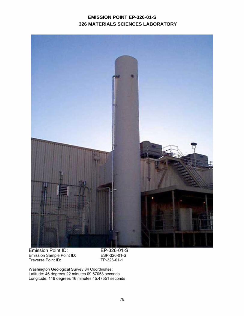
EMISSION POINT EP-326-01-S 326 MATERIALS SCIENCES LABORATORY
78
Emission Point ID: EP-326-01-S Emission Sample Point ID: ESP-326-01-S Traverse Point ID: TP-326-01-1 Washington Geological Survey 84 Coordinates: Latitude: 46 degrees 22 minutes 09.67053 seconds Longitude: 119 degrees 16 minutes 45.47551 seconds
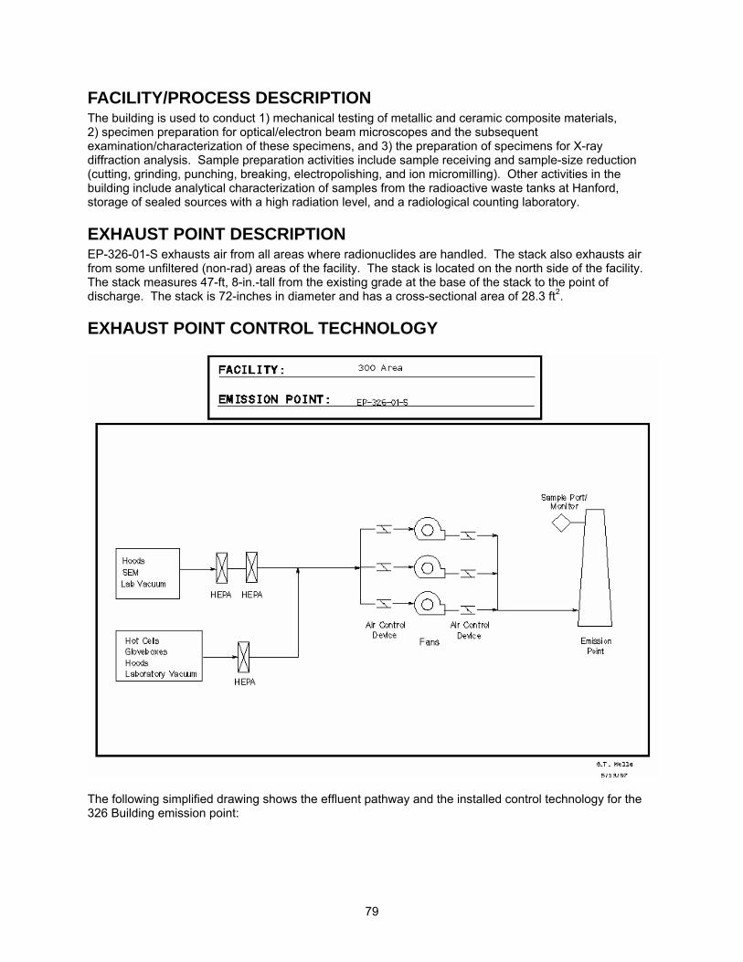
79
FACILITY/PROCESS DESCRIPTION The building is used to conduct 1) mechanical testing of metallic and ceramic composite materials, 2) specimen preparation for optical/electron beam microscopes and the subsequent examination/characterization of these specimens, and 3) the preparation of specimens for X-ray diffraction analysis. Sample preparation activities include sample receiving and sample-size reduction (cutting, grinding, punching, breaking, electropolishing, and ion micromilling). Other activities in the building include analytical characterization of samples from the radioactive waste tanks at Hanford, storage of sealed sources with a high radiation level, and a radiological counting laboratory.
EXHAUST POINT DESCRIPTION EP-326-01-S exhausts air from all areas where radionuclides are handled. The stack also exhausts air from some unfiltered (non-rad) areas of the facility. The stack is located on the north side of the facility. The stack measures 47-ft, 8-in.-tall from the existing grade at the base of the stack to the point of discharge. The stack is 72-inches in diameter and has a cross-sectional area of 28.3 ft2.
EXHAUST POINT CONTROL TECHNOLOGY
The following simplified drawing shows the effluent pathway and the installed control technology for the 326 Building emission point:
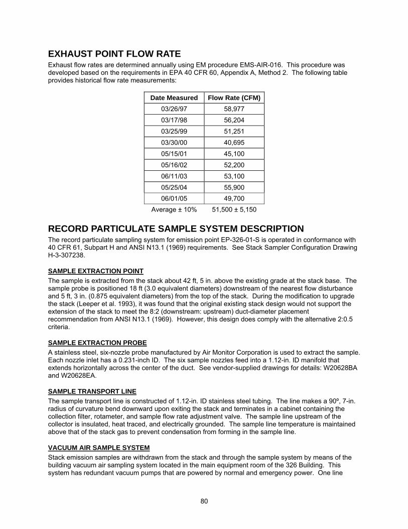
80
EXHAUST POINT FLOW RATE Exhaust flow rates are determined annually using EM procedure EMS-AIR-016. This procedure was developed based on the requirements in EPA 40 CFR 60, Appendix A, Method 2. The following table provides historical flow rate measurements:
Date Measured Flow Rate (CFM)03/26/97 58,977
03/17/98 56,204
03/25/99 51,251
03/30/00 40,695
05/15/01 45,100
05/16/02 52,200
06/11/03 53,100
05/25/04 55,900 06/01/05 49,700
Average ± 10% 51,500 ± 5,150
RECORD PARTICULATE SAMPLE SYSTEM DESCRIPTION The record particulate sampling system for emission point EP-326-01-S is operated in conformance with 40 CFR 61, Subpart H and ANSI N13.1 (1969) requirements. See Stack Sampler Configuration Drawing H-3-307238.
SAMPLE EXTRACTION POINT The sample is extracted from the stack about 42 ft, 5 in. above the existing grade at the stack base. The sample probe is positioned 18 ft (3.0 equivalent diameters) downstream of the nearest flow disturbance and 5 ft, 3 in. (0.875 equivalent diameters) from the top of the stack. During the modification to upgrade the stack (Leeper et al. 1993), it was found that the original existing stack design would not support the extension of the stack to meet the 8:2 (downstream: upstream) duct-diameter placement recommendation from ANSI N13.1 (1969). However, this design does comply with the alternative 2:0.5 criteria.
SAMPLE EXTRACTION PROBE A stainless steel, six-nozzle probe manufactured by Air Monitor Corporation is used to extract the sample. Each nozzle inlet has a 0.231-inch ID. The six sample nozzles feed into a 1.12-in. ID manifold that extends horizontally across the center of the duct. See vendor-supplied drawings for details: W20628BA and W20628EA.
SAMPLE TRANSPORT LINE The sample transport line is constructed of 1.12-in. ID stainless steel tubing. The line makes a 90º, 7-in. radius of curvature bend downward upon exiting the stack and terminates in a cabinet containing the collection filter, rotameter, and sample flow rate adjustment valve. The sample line upstream of the collector is insulated, heat traced, and electrically grounded. The sample line temperature is maintained above that of the stack gas to prevent condensation from forming in the sample line.
VACUUM AIR SAMPLE SYSTEM Stack emission samples are withdrawn from the stack and through the sample system by means of the building vacuum air sampling system located in the main equipment room of the 326 Building. This system has redundant vacuum pumps that are powered by normal and emergency power. One line
81
drawing of this system is under development and will be added as an attachment to this section when complete.
BATTELLE DRAWINGS NUMBER Stack Sampler Configuration EP-326-01-S; Rev. 0 H-3-307238 The above drawing is not currently available to view electronically via this website. Electronic access to these drawings is available via the Auto Manager® Software Program. Contact Shanna Abbott for AutoManager® access. AIR MONITOR CORP. DRAWINGS NUMBER Sampler-Probe Assembly; Rev. 2 W20628BA Iso-Sampling Threaded Nozzle; Rev. 1 W20628EA Other drawings are provided by the vendor and are not available electronically at this time. For copies or questions regarding the drawings, contact Cheryl Duchsherer at 373-0594.
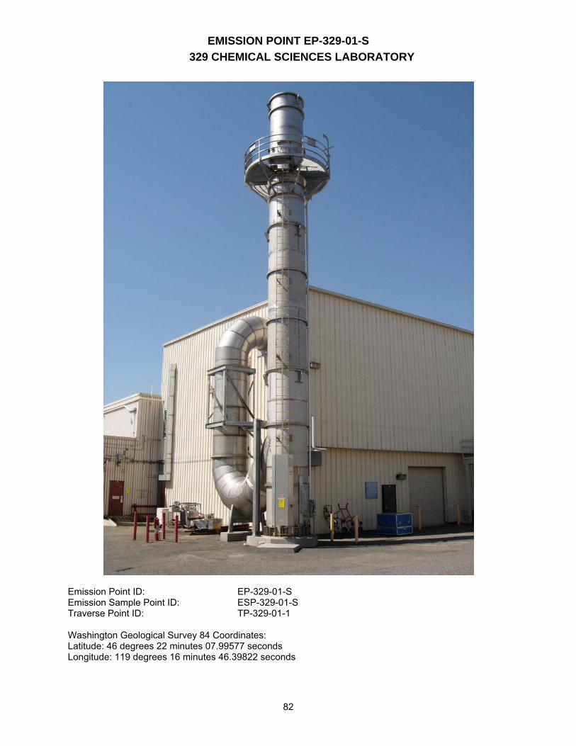
EMISSION POINT EP-329-01-S 329 CHEMICAL SCIENCES LABORATORY
82
Emission Point ID: EP-329-01-S Emission Sample Point ID: ESP-329-01-S Traverse Point ID: TP-329-01-1 Washington Geological Survey 84 Coordinates: Latitude: 46 degrees 22 minutes 07.99577 seconds Longitude: 119 degrees 16 minutes 46.39822 seconds
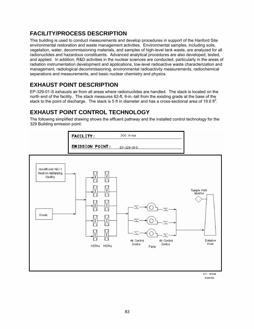
83
FACILITY/PROCESS DESCRIPTION This building is used to conduct measurements and develop procedures in support of the Hanford Site environmental restoration and waste management activities. Environmental samples, including soils, vegetation, water, decommissioning materials, and samples of high-level tank waste, are analyzed for all radionuclides and hazardous constituents. Advanced analytical procedures are also developed, tested, and applied. In addition, R&D activities in the nuclear sciences are conducted, particularly in the areas of radiation instrumentation development and applications, low-level radioactive waste characterization and management, radiological decommissioning, environmental radioactivity measurements, radiochemical separations and measurements, and basic nuclear chemistry and physics.
EXHAUST POINT DESCRIPTION EP-329-01-S exhausts air from all areas where radionuclides are handled. The stack is located on the north end of the facility. The stack measures 62-ft, 6-in.-tall from the existing grade at the base of the stack to the point of discharge. The stack is 5 ft in diameter and has a cross-sectional area of 19.6 ft2.
EXHAUST POINT CONTROL TECHNOLOGY The following simplified drawing shows the effluent pathway and the installed control technology for the 329 Building emission point:
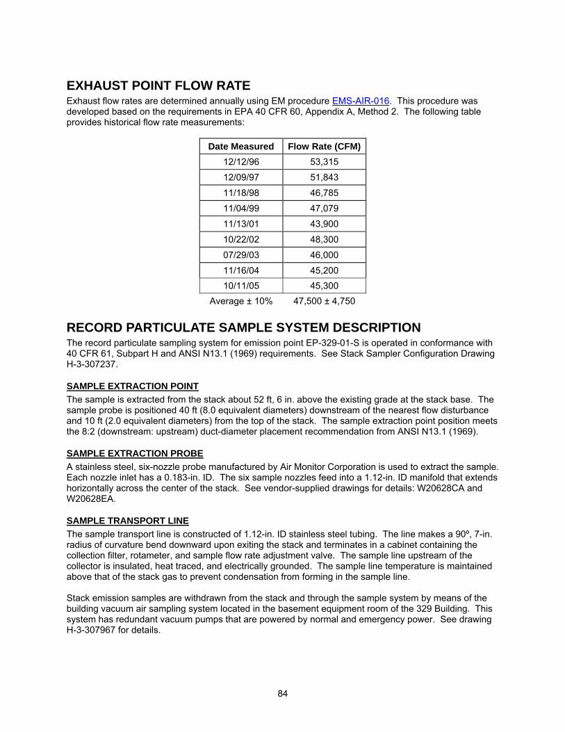
84
EXHAUST POINT FLOW RATE Exhaust flow rates are determined annually using EM procedure EMS-AIR-016. This procedure was developed based on the requirements in EPA 40 CFR 60, Appendix A, Method 2. The following table provides historical flow rate measurements:
Date Measured Flow Rate (CFM)12/12/96 53,315
12/09/97 51,843
11/18/98 46,785
11/04/99 47,079
11/13/01 43,900
10/22/02 48,300
07/29/03 46,000
11/16/04 45,200 10/11/05 45,300
Average ± 10% 47,500 ± 4,750
RECORD PARTICULATE SAMPLE SYSTEM DESCRIPTION The record particulate sampling system for emission point EP-329-01-S is operated in conformance with 40 CFR 61, Subpart H and ANSI N13.1 (1969) requirements. See Stack Sampler Configuration Drawing H-3-307237.
SAMPLE EXTRACTION POINT The sample is extracted from the stack about 52 ft, 6 in. above the existing grade at the stack base. The sample probe is positioned 40 ft (8.0 equivalent diameters) downstream of the nearest flow disturbance and 10 ft (2.0 equivalent diameters) from the top of the stack. The sample extraction point position meets the 8:2 (downstream: upstream) duct-diameter placement recommendation from ANSI N13.1 (1969).
SAMPLE EXTRACTION PROBE A stainless steel, six-nozzle probe manufactured by Air Monitor Corporation is used to extract the sample. Each nozzle inlet has a 0.183-in. ID. The six sample nozzles feed into a 1.12-in. ID manifold that extends horizontally across the center of the stack. See vendor-supplied drawings for details: W20628CA and W20628EA.
SAMPLE TRANSPORT LINE The sample transport line is constructed of 1.12-in. ID stainless steel tubing. The line makes a 90º, 7-in. radius of curvature bend downward upon exiting the stack and terminates in a cabinet containing the collection filter, rotameter, and sample flow rate adjustment valve. The sample line upstream of the collector is insulated, heat traced, and electrically grounded. The sample line temperature is maintained above that of the stack gas to prevent condensation from forming in the sample line. Stack emission samples are withdrawn from the stack and through the sample system by means of the building vacuum air sampling system located in the basement equipment room of the 329 Building. This system has redundant vacuum pumps that are powered by normal and emergency power. See drawing H-3-307967 for details.
85
BATTELLE DRAWINGS NUMBER Stack Sampler Configuration EP-329-01-S; Rev. 0 H-3-307237 Vacuum Air Sample Piping Schematic; Rev. 0 H-3-307967 The above drawings are not currently available to view electronically via this website. Electronic access to these drawings is available via the AutoManager® Software Program. Contact Shanna Abbott for AutoManager® access. AIR MONITOR CORP. DRAWINGS NUMBER Flo-Sampler Probe Assembly; Rev. 2 W20628CA Iso-Sampling Threaded Nozzle; Rev. 1 W20628EA Other drawings are provided by the vendor and are not available electronically at this time. For copies or questions regarding the drawings, contact Cheryl Duchsherer at 373-0594.
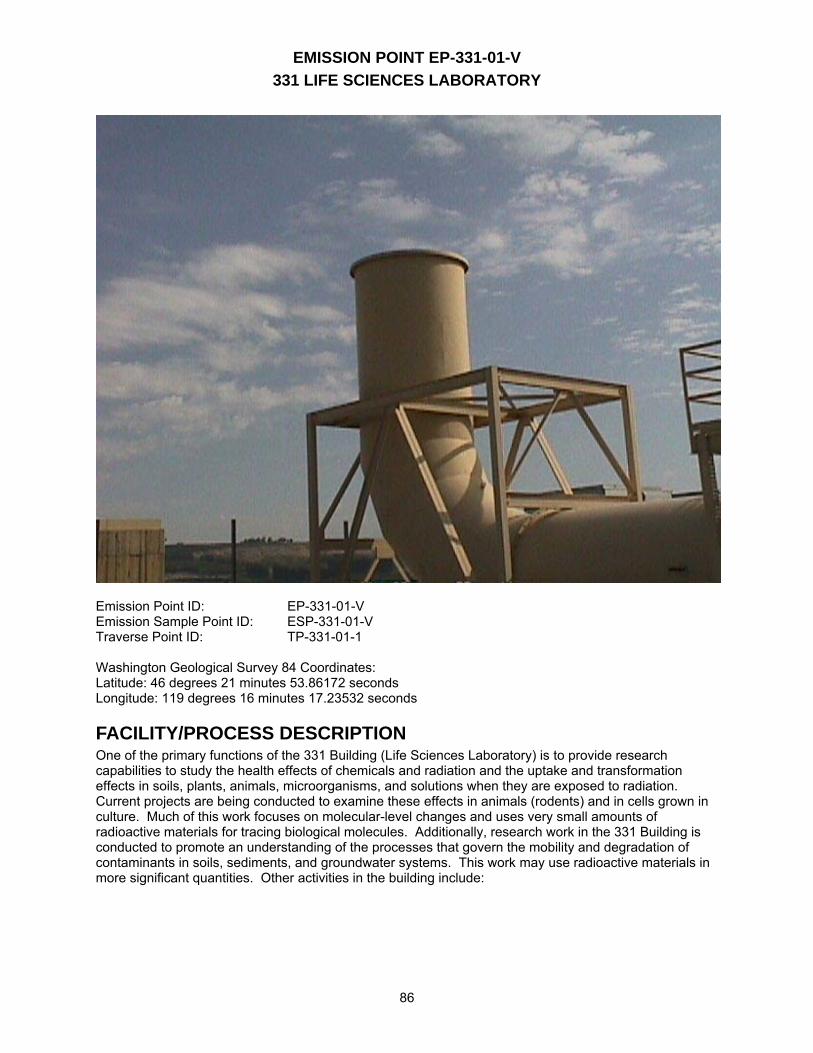
EMISSION POINT EP-331-01-V 331 LIFE SCIENCES LABORATORY
86
Emission Point ID: EP-331-01-V Emission Sample Point ID: ESP-331-01-V Traverse Point ID: TP-331-01-1 Washington Geological Survey 84 Coordinates: Latitude: 46 degrees 21 minutes 53.86172 seconds Longitude: 119 degrees 16 minutes 17.23532 seconds
FACILITY/PROCESS DESCRIPTION One of the primary functions of the 331 Building (Life Sciences Laboratory) is to provide research capabilities to study the health effects of chemicals and radiation and the uptake and transformation effects in soils, plants, animals, microorganisms, and solutions when they are exposed to radiation. Current projects are being conducted to examine these effects in animals (rodents) and in cells grown in culture. Much of this work focuses on molecular-level changes and uses very small amounts of radioactive materials for tracing biological molecules. Additionally, research work in the 331 Building is conducted to promote an understanding of the processes that govern the mobility and degradation of contaminants in soils, sediments, and groundwater systems. This work may use radioactive materials in more significant quantities. Other activities in the building include:
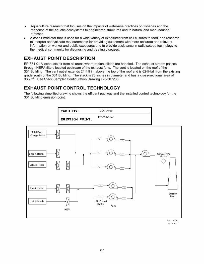
87
• Aquaculture research that focuses on the impacts of water-use practices on fisheries and the response of the aquatic ecosystems to engineered structures and to natural and man-induced stresses.
• A cobalt irradiator that is used for a wide variety of exposures from cell cultures to food, and research to interpret and validate measurements for providing customers with more accurate and relevant information on worker and public exposures and to provide assistance in radioisotope technology to the medical community for diagnosing and treating diseases.
EXHAUST POINT DESCRIPTION EP-331-01-V exhausts air from all areas where radionuclides are handled. The exhaust stream passes through HEPA filters located upstream of the exhaust fans. The vent is located on the roof of the 331 Building. The vent outlet extends 24 ft 9 in. above the top of the roof and is 62-ft-tall from the existing grade south of the 331 Building. The stack is 78 inches in diameter and has a cross-sectional area of 33.2 ft2. See Stack Sampler Configuration Drawing H-3-307236.
EXHAUST POINT CONTROL TECHNOLOGY The following simplified drawing shows the effluent pathway and the installed control technology for the 331 Building emission point:
EP-331-01-V
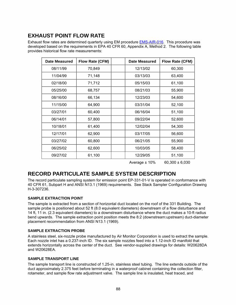
88
EXHAUST POINT FLOW RATE Exhaust flow rates are determined quarterly using EM procedure EMS-AIR-016. This procedure was developed based on the requirements in EPA 40 CFR 60, Appendix A, Method 2. The following table provides historical flow rate measurements:
Date Measured Flow Rate (CFM) Date Measured Flow Rate (CFM)
08/11/99 70,849 12/13/02 60,300
11/04/99 71,148 03/13/03 63,400
02/18/00 71,712 05/15/03 61,100
05/25/00 68,757 08/21/03 55,900
08/16/00 66,134 12/23/03 54,600
11/15/00 64,900 03/31/04 52,100
03/27/01 60,400 06/16/04 51,100
06/14/01 57,800 09/22/04 52,600
10/18/01 61,400 12/02/04 54,300
12/17/01 62,900 03/17/05 56,600
03/27/02 60,800 06/21/05 55,900
06/25/02 62,600 10/03/05 58,400
09/27/02 61,100 12/29/05 51,100
Average ± 10% 60,300 ± 6,030
RECORD PARTICULATE SAMPLE SYSTEM DESCRIPTION The record particulate sampling system for emission point EP-331-01-V is operated in conformance with 40 CFR 61, Subpart H and ANSI N13.1 (1969) requirements. See Stack Sampler Configuration Drawing H-3-307236.
SAMPLE EXTRACTION POINT The sample is extracted from a section of horizontal duct located on the roof of the 331 Building. The sample probe is positioned about 52 ft (8.0 equivalent diameters) downstream of a flow disturbance and 14 ft, 11 in. (2.3 equivalent diameters) to a downstream disturbance where the duct makes a 10-ft radius bend upwards. The sample extraction point position meets the 8:2 (downstream:upstream) duct-diameter placement recommendation from ANSI N13.1 (1969).
SAMPLE EXTRACTION PROBE A stainless steel, six-nozzle probe manufactured by Air Monitor Corporation is used to extract the sample. Each nozzle inlet has a 0.237-inch ID. The six sample nozzles feed into a 1.12-inch ID manifold that extends horizontally across the center of the duct. See vendor-supplied drawings for details: W20628DA and W20628EA.
SAMPLE TRANSPORT LINE The sample transport line is constructed of 1.25-in. stainless steel tubing. The line extends outside of the duct approximately 2.375 feet before terminating in a waterproof cabinet containing the collection filter, rotameter, and sample flow rate adjustment valve. The sample line is insulated, heat traced, and
89
electrically grounded. The sample line temperature is maintained above that of the stack gas to prevent condensation from forming in the sample line.
VACUUM AIR SAMPLE SYSTEM Stack emission samples are withdrawn from the stack and through the sample system by means of the building vacuum air sampling system located in the second floor equipment room of the 331 Building. This system has redundant blowers that are powered by normal and emergency power. See Vacuum Air Sampling One-Line Diagram Drawing H-3-307559 for details.
BATTELLE DRAWINGS NUMBER Stack Sampler Configuration EP-331-01-V; Rev. 0 H-3-307236 Vacuum Air Sampling One-Line Diagram; Rev. 0 H-3-307559 The above drawings are not currently available to view electronically via this website. Electronic access to these drawings is available via the AutoManager® Software Program. Contact Shanna Abbott for AutoManager® access. AIR MONITOR CORP. DRAWINGS NUMBER Flo-Sampler Probe Assembly; Rev. 2 W20628DA Iso-Sampling Threaded Nozzle; Rev. 1 W20628EA Other drawings are provided by the vendor and are not available electronically at this time. For copies or questions regarding the drawings, contact Cheryl Duchsherer at 373-0594.
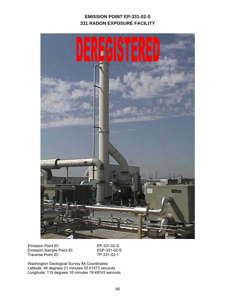
EMISSION POINT EP-331-02-S 331 RADON EXPOSURE FACILITY
90
Emission Point ID: EP-331-02-S Emission Sample Point ID: ESP-331-02-S Traverse Point ID: TP-331-02-1 Washington Geological Survey 84 Coordinates: Latitude: 46 degrees 21 minutes 53.61473 seconds Longitude: 119 degrees 16 minutes 19.49743 seconds
91
FACILITY/PROCESS DESCRIPTION The 331 Radon Exposure Facility was designed to be used as an animal and cell exposure facility. It is composed of four rooms located on the west end of the main 331 Building. This part of the facility has its own supply and exhaust system, and currently the exhaust is not high-efficiency particulate air-filtered. The facility contains a radon holdup system control technology designed to allow for the decay of radon gas and the collection of its particulate daughters before discharging the treated gas via the stack located on the roof. The radon holdup system is not currently connected to the exhaust system. The planned radon inhalation research was never initiated because of loss of funding.
EXHAUST POINT DESCRIPTION The emission point was deregistered with the WDOH on March 21st2003. This emission point still remains operational for non-radioactive projects.(2)
NOTE: The following details are provided for information purposes only: EP-331-02-S exhausts non-filtered room air from Rooms 195 through 198. The stack is located atop the 11 ft 3-in.high facility. The stack measures 31 ft-tall from the top of the roof to the point of discharge. This gives the emission point an effective height above the existing grade of 42 ft, 3 in. The stack is 24 inches in diameter and has a cross-sectional area of 3.1 ft2.
EXHAUST POINT CONTROL TECHNOLOGY No control technology is in place at this time.
EXHAUST POINT FLOW RATE Exhaust flow rates were determined annually using PNNL Operating Procedure SOP AIR BALANCE-4. This procedure was developed based on the requirements in EPA 40 CFR 60, Appendix A, Method 2. The following table provides historical flow rate measurements:
Date Measured Flow Rate (CFM)05/05/98 4,752 06/02/99 4,926
Average ± 10% 4,840 ± 484 Note: Annual stack flow measurements were canceled in year 2000.
RECORD PARTICULATE SAMPLE SYSTEM DESCRIPTION No stack sampling is being performed or is required at this time. The following details are provided for information purposes only: The stack sampling system meets the requirements in 40 CFR 61, Subpart H and ANSI N13.1 (1969). See attached Stack Sampler Configuration Drawing H-3-307827. (2) Letter, AW Conklin, Washington Department of Health, to JB Hebdon, US Department of Energy,
dated March 21 2003, # AIR 03-306, audit # 312.
92
SAMPLE EXTRACTION POINT The sample would be extracted from the stack about 27 ft, 2.25 in. above the stack base. The sample probe is positioned 15 ft, 0.75 in. (7.43 equivalent diameters) downstream of the nearest flow disturbance and 4 ft (2.67 equivalent diameters) from the top of the stack. The stack meets the alternative 2:0.5 (downstream: upstream) duct-diameter placement recommendation from ANSI 1969.
SAMPLE EXTRACTION PROBE A stainless steel, four-nozzle probe manufactured by Air Monitor Corporation was used to extract the sample. Each nozzle inlet has a 0.271-in. ID. The nozzles have an 8-degree taper and feed into a common manifold with an ID of 1.12-inches. The sample manifold extends outside the stack 12 in., makes a 6-in. radius bend downward, and unites with the sample transport line. See attached vendor-supplied drawings for details: W23386CA, W23386CB, W23386CC, and W23386CD.
SAMPLE TRANSPORT LINE The sample transport line is constructed of 1.12-in. ID stainless steel tubing. The line extends downward and terminates in a cabinet containing the collection filter, rotameter, and sample flow rate adjustment valve. The sample line upstream of the collector is insulated, heat traced, and electrically grounded. The sample line temperature is maintained above that of the stack gas to prevent condensation from forming in the sample line.
VACUUM AIR SAMPLE SYSTEM If stack emission samples were to be withdrawn from the stack, they would be drawn by means of the building vacuum air sampling system located in the second floor equipment room of the 331 Building. This system has redundant blowers that are powered by normal and emergency power. See attached Vacuum Air Sampling One-Line Diagram drawing H-3-307559 for details.
BATTELLE DRAWINGS NUMBER Stack Sampler Configuration EP-331-02-S; Rev. 0 H-3-307827 Vacuum Air Sampling One-Line Diagram; Rev. 0 H-3-307559 The above drawings are not currently available to view electronically via this website. Electronic access to these drawings is available via the AutoManager® Software Program. Contact Shanna Abbott for AutoManager® access.
AIR MONITOR CORP. DRAWINGS NUMBER #331 Isokinetic Sampling Probe; Rev. 1 W23386CA Iso-Sampling Threaded Nozzle; Rev. 0 W23386CB #331 Isokinetic Sampling Manifold; Rev. 0 W23386CC #331 Iso Sampling Probe Plate, Plug and Fitting; Rev. 1 W23386CD Other drawings are provided by the vendor and are not available electronically at this time. For copies or questions regarding the drawings, contact Cheryl Duchsherer at 373-0594.
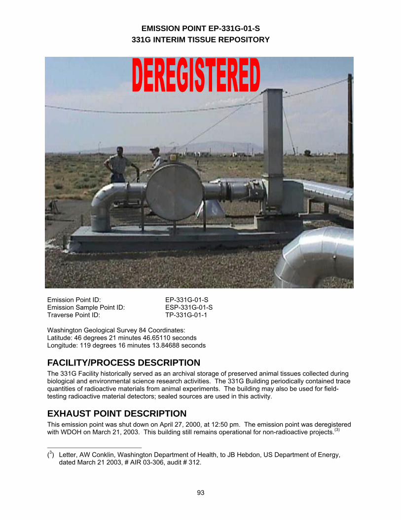
EMISSION POINT EP-331G-01-S 331G INTERIM TISSUE REPOSITORY
93
Emission Point ID: EP-331G-01-S Emission Sample Point ID: ESP-331G-01-S Traverse Point ID: TP-331G-01-1 Washington Geological Survey 84 Coordinates: Latitude: 46 degrees 21 minutes 46.65110 seconds Longitude: 119 degrees 16 minutes 13.84688 seconds
FACILITY/PROCESS DESCRIPTION The 331G Facility historically served as an archival storage of preserved animal tissues collected during biological and environmental science research activities. The 331G Building periodically contained trace quantities of radioactive materials from animal experiments. The building may also be used for field-testing radioactive material detectors; sealed sources are used in this activity.
EXHAUST POINT DESCRIPTION This emission point was shut down on April 27, 2000, at 12:50 pm. The emission point was deregistered with WDOH on March 21, 2003. This building still remains operational for non-radioactive projects.(3) (3) Letter, AW Conklin, Washington Department of Health, to JB Hebdon, US Department of Energy,
dated March 21 2003, # AIR 03-306, audit # 312.
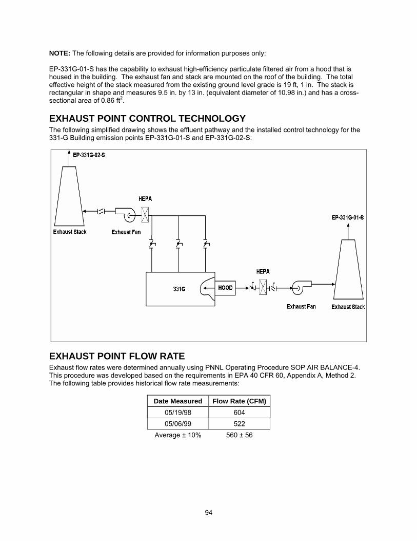
94
NOTE: The following details are provided for information purposes only: EP-331G-01-S has the capability to exhaust high-efficiency particulate filtered air from a hood that is housed in the building. The exhaust fan and stack are mounted on the roof of the building. The total effective height of the stack measured from the existing ground level grade is 19 ft, 1 in. The stack is rectangular in shape and measures 9.5 in. by 13 in. (equivalent diameter of 10.98 in.) and has a cross-sectional area of 0.86 ft2.
EXHAUST POINT CONTROL TECHNOLOGY The following simplified drawing shows the effluent pathway and the installed control technology for the 331-G Building emission points EP-331G-01-S and EP-331G-02-S:
EXHAUST POINT FLOW RATE Exhaust flow rates were determined annually using PNNL Operating Procedure SOP AIR BALANCE-4. This procedure was developed based on the requirements in EPA 40 CFR 60, Appendix A, Method 2. The following table provides historical flow rate measurements:
Date Measured Flow Rate (CFM)05/19/98 604 05/06/99 522
Average ± 10% 560 ± 56
95
Note: Annual stack flow measurements were canceled in year 2000.
RECORD PARTICULATE SAMPLE SYSTEM DESCRIPTION Emission point EP-331G-01-S was a minor emission point and does not have a sample system installed. See attached Stack Sampler Configuration Drawing H-3-307825.
96
BATTELLE DRAWINGS NUMBER Stack Configuration EP-331G-01-S & EP-331G-02-S H-3-307825 The above drawing is not currently available to view electronically via this website. Electronic access to these drawings is available via the AutoManager® Software Program. Contact Shanna Abbott for AutoManager® access.
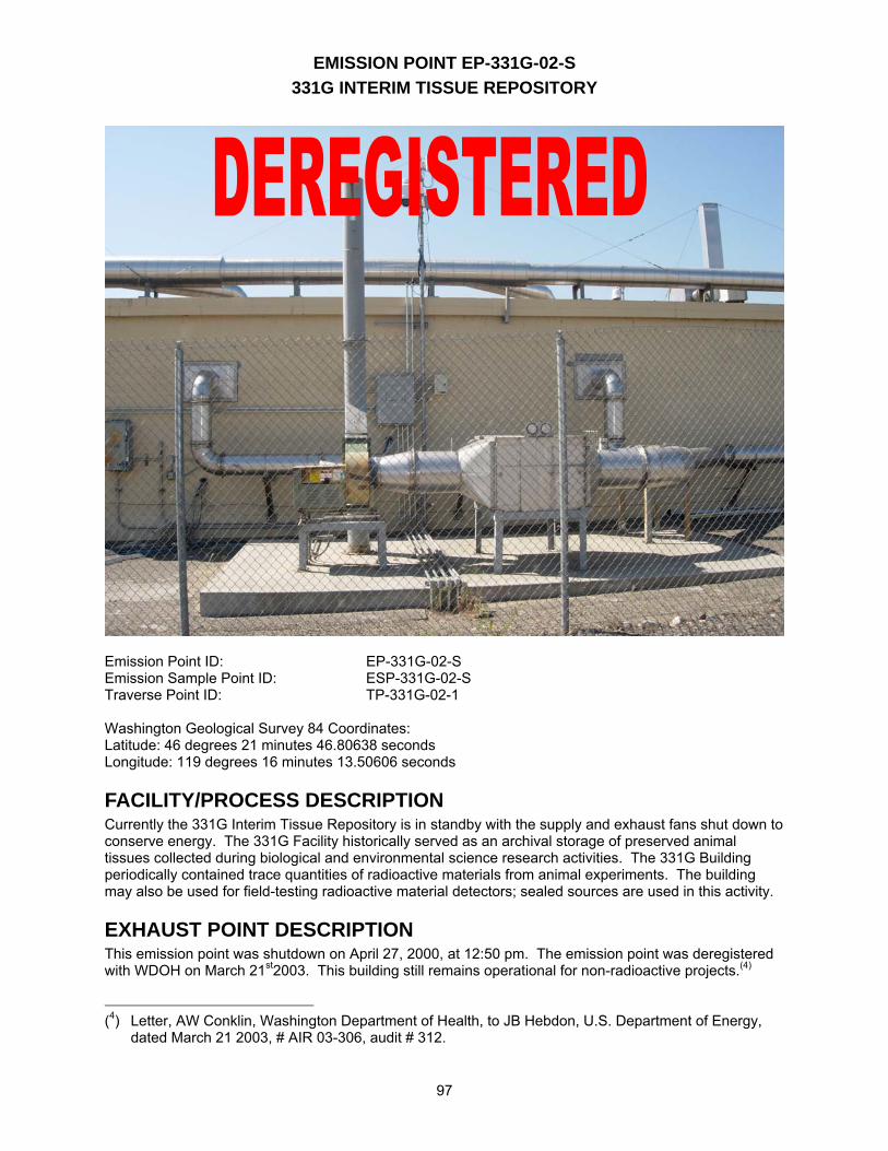
EMISSION POINT EP-331G-02-S 331G INTERIM TISSUE REPOSITORY
97
Emission Point ID: EP-331G-02-S Emission Sample Point ID: ESP-331G-02-S Traverse Point ID: TP-331G-02-1 Washington Geological Survey 84 Coordinates: Latitude: 46 degrees 21 minutes 46.80638 seconds Longitude: 119 degrees 16 minutes 13.50606 seconds
FACILITY/PROCESS DESCRIPTION Currently the 331G Interim Tissue Repository is in standby with the supply and exhaust fans shut down to conserve energy. The 331G Facility historically served as an archival storage of preserved animal tissues collected during biological and environmental science research activities. The 331G Building periodically contained trace quantities of radioactive materials from animal experiments. The building may also be used for field-testing radioactive material detectors; sealed sources are used in this activity.
EXHAUST POINT DESCRIPTION This emission point was shutdown on April 27, 2000, at 12:50 pm. The emission point was deregistered with WDOH on March 21st2003. This building still remains operational for non-radioactive projects.(4)
(4) Letter, AW Conklin, Washington Department of Health, to JB Hebdon, U.S. Department of Energy,
dated March 21 2003, # AIR 03-306, audit # 312.
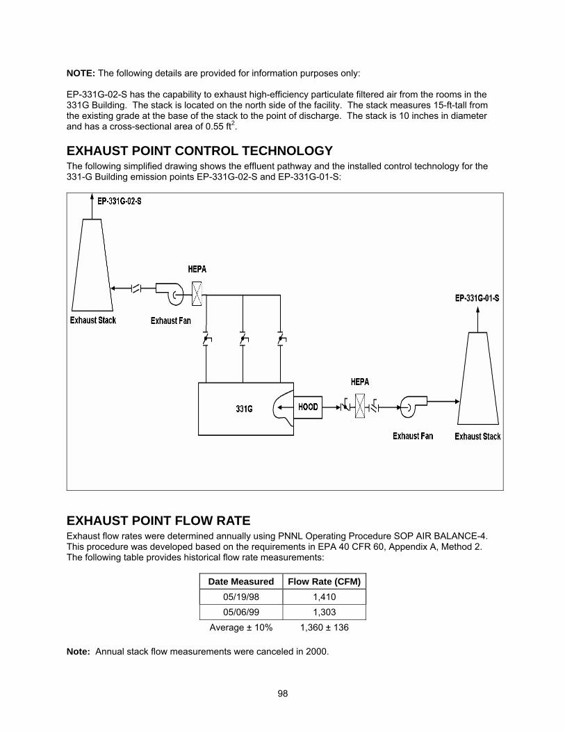
98
NOTE: The following details are provided for information purposes only: EP-331G-02-S has the capability to exhaust high-efficiency particulate filtered air from the rooms in the 331G Building. The stack is located on the north side of the facility. The stack measures 15-ft-tall from the existing grade at the base of the stack to the point of discharge. The stack is 10 inches in diameter and has a cross-sectional area of 0.55 ft2.
EXHAUST POINT CONTROL TECHNOLOGY The following simplified drawing shows the effluent pathway and the installed control technology for the 331-G Building emission points EP-331G-02-S and EP-331G-01-S:
EXHAUST POINT FLOW RATE Exhaust flow rates were determined annually using PNNL Operating Procedure SOP AIR BALANCE-4. This procedure was developed based on the requirements in EPA 40 CFR 60, Appendix A, Method 2. The following table provides historical flow rate measurements:
Date Measured Flow Rate (CFM)05/19/98 1,410 05/06/99 1,303
Average ± 10% 1,360 ± 136
Note: Annual stack flow measurements were canceled in 2000.
99
RECORD PARTICULATE SAMPLE SYSTEM DESCRIPTION Emission point EP-331G-02-S was a minor emission point and does not have a sample system installed. See attached Stack Sampler Configuration Drawing H-3-307825.
BATTELLE DRAWINGS NUMBER Stack Configuration EP-331G-01-S & EP-331G-02-S H-3-307825 The above drawing is not currently available to view electronically via this website. Electronic access to these drawings is available via the AutoManager® Software Program. Contact Shanna Abbott for AutoManager® access.
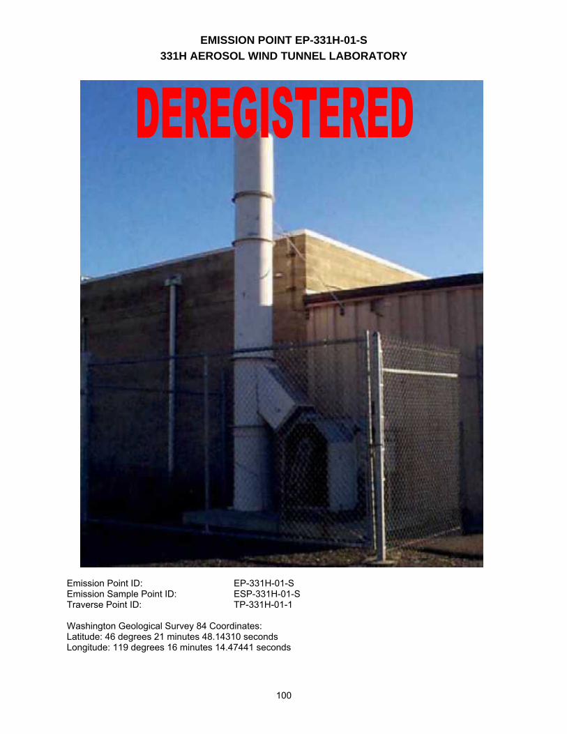
EMISSION POINT EP-331H-01-S 331H AEROSOL WIND TUNNEL LABORATORY
100
Emission Point ID: EP-331H-01-S Emission Sample Point ID: ESP-331H-01-S Traverse Point ID: TP-331H-01-1 Washington Geological Survey 84 Coordinates: Latitude: 46 degrees 21 minutes 48.14310 seconds Longitude: 119 degrees 16 minutes 14.47441 seconds
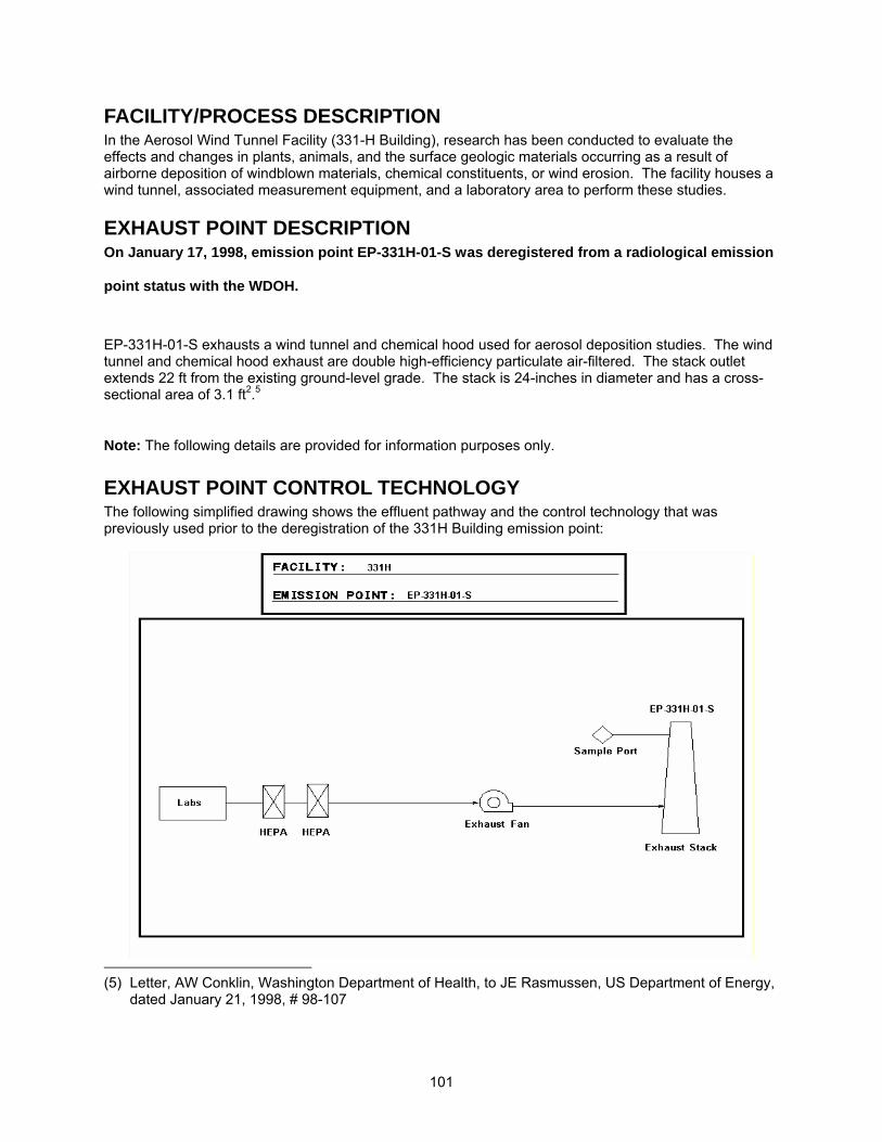
101
FACILITY/PROCESS DESCRIPTION In the Aerosol Wind Tunnel Facility (331-H Building), research has been conducted to evaluate the effects and changes in plants, animals, and the surface geologic materials occurring as a result of airborne deposition of windblown materials, chemical constituents, or wind erosion. The facility houses a wind tunnel, associated measurement equipment, and a laboratory area to perform these studies.
EXHAUST POINT DESCRIPTION On January 17, 1998, emission point EP-331H-01-S was deregistered from a radiological emission
point status with the WDOH.
EP-331H-01-S exhausts a wind tunnel and chemical hood used for aerosol deposition studies. The wind tunnel and chemical hood exhaust are double high-efficiency particulate air-filtered. The stack outlet extends 22 ft from the existing ground-level grade. The stack is 24-inches in diameter and has a cross-sectional area of 3.1 ft2.5
Note: The following details are provided for information purposes only.
EXHAUST POINT CONTROL TECHNOLOGY The following simplified drawing shows the effluent pathway and the control technology that was previously used prior to the deregistration of the 331H Building emission point:
(5) Letter, AW Conklin, Washington Department of Health, to JE Rasmussen, US Department of Energy,
dated January 21, 1998, # 98-107
102
Note: On January 17, 1998 emission point EP-331H-01-S was deregistered with WDOH. In this process, it was established that there would be no need for an active or passive ventilation system with emission control and/or monitoring devices. Since then, the primary HEPA filter was removed from the above system. The figure was not modified to show the reduction in control technology. EXHAUST POINT FLOW RATE Exhaust flow rates were determined annually using PNNL Operating Procedure SOP AIR BALANCE-4. This procedure was developed based on the requirements in EPA 40 CFR 60, Appendix A, Method 2. The following table provides historical flow rate measurements:
Date Measured Flow Rate (CFM)10/18/95 7,301
10/04/96 6,358
10/23/97 5,679 10/27/98 5,276
Average ± 10% 6,150 ± 615
Note: Flow measurements were canceled from the annual frequency in the year 2000.
RECORD PARTICULATE SAMPLE SYSTEM DESCRIPTION The record particulate sampling system for emission point EP-331H-01-S was operated in conformance with 40 CFR 61, Subpart H and ANSI N13.1 (1969) requirements. See attached Stack Sampler Configuration Drawing H-3-307247.
SAMPLE EXTRACTION POINT The sample was extracted from the stack about 17 ft, 3 in. above the existing grade at the stack base. The sample probe is positioned 9 ft, 6.38 in. (4.8 equivalent diameters) downstream of the nearest flow disturbance and 4 ft, 3 in. (2.1 equivalent diameters) from the top of the stack. The stack meets the alternative 2:0.5 (downstream: upstream) duct-diameter placement recommendation from the ANSI N13.1 (1969) standard.
SAMPLE EXTRACTION PROBE A stainless steel, eight-nozzle probe was used to extract the sample. The sample nozzles are positioned in two concentric rings, with two nozzles located in each quadrant, as shown on the Air Monitor Corporation Drawing Number PND-62-503. Each nozzle inlet has a 0.156-in. ID. The eight sample nozzles eventually feed into a common 0.495-in. ID manifold. The manifold extends to within 4 in. of the stack wall where it is united with the sample transport line.
SAMPLE TRANSPORT LINE The sample transport line is constructed of 0.495-inch ID stainless steel tubing. The line extends approximately 5 in. outside the stack before making a 7-in. radius bend and extending downward at a slope of 45 degrees. The sample line extends for 8 ft 3 in. before making a 7-in. radius bend in the opposite direction. The line extends another 2 ft before terminating at the collection filter, rotameter, and sample flow rate adjustment valve inside the facility equipment room. The sample line is insulated from the point where it exits the stack to the point where it penetrates the equipment room wall.
VACUUM AIR SAMPLE SYSTEM Stack emission samples are withdrawn from the stack by means of the building vacuum air-sampling pump located in the south equipment room. This single pump powered by normal and emergency power.

103
BATTELLE DRAWINGS NUMBER Stack Sampler Configuration EP-331H-01-S; Rev. 0 H-3-307247 The above drawing is not currently available to view electronically via this website. Electronic access to these drawings is available via the AutoManager® Software Program. Contact Shanna Abbott for AutoManager® access. AIR MONITOR CORP. DRAWINGS NUMBER Manifold, Isokinetic; Rev. A PND-62-503 Other drawings are provided by the vendor and are not available electronically at this time. For copies or questions regarding the drawings, contact Cheryl Duchsherer at 373-0594.
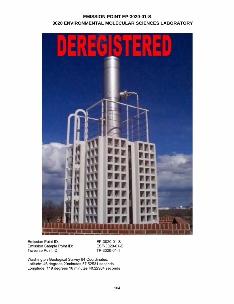
EMISSION POINT EP-3020-01-S 3020 ENVIRONMENTAL MOLECULAR SCIENCES LABORATORY
104
Emission Point ID: EP-3020-01-S Emission Sample Point ID: ESP-3020-01-S Traverse Point ID: TP-3020-01-1 Washington Geological Survey 84 Coordinates: Latitude: 46 degrees 20minutes 57.52531 seconds Longitude: 119 degrees 16 minutes 40.22984 seconds
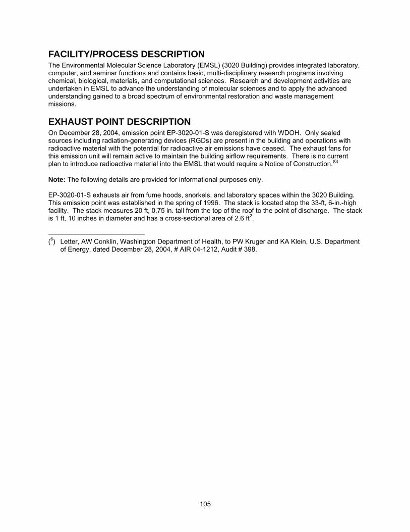
105
FACILITY/PROCESS DESCRIPTION The Environmental Molecular Science Laboratory (EMSL) (3020 Building) provides integrated laboratory, computer, and seminar functions and contains basic, multi-disciplinary research programs involving chemical, biological, materials, and computational sciences. Research and development activities are undertaken in EMSL to advance the understanding of molecular sciences and to apply the advanced understanding gained to a broad spectrum of environmental restoration and waste management missions.
EXHAUST POINT DESCRIPTION On December 28, 2004, emission point EP-3020-01-S was deregistered with WDOH. Only sealed sources including radiation-generating devices (RGDs) are present in the building and operations with radioactive material with the potential for radioactive air emissions have ceased. The exhaust fans for this emission unit will remain active to maintain the building airflow requirements. There is no current plan to introduce radioactive material into the EMSL that would require a Notice of Construction.(6) Note: The following details are provided for informational purposes only. EP-3020-01-S exhausts air from fume hoods, snorkels, and laboratory spaces within the 3020 Building. This emission point was established in the spring of 1996. The stack is located atop the 33-ft, 6-in.-high facility. The stack measures 20 ft, 0.75 in. tall from the top of the roof to the point of discharge. The stack is 1 ft, 10 inches in diameter and has a cross-sectional area of 2.6 ft2. (6) Letter, AW Conklin, Washington Department of Health, to PW Kruger and KA Klein, U.S. Department
of Energy, dated December 28, 2004, # AIR 04-1212, Audit # 398.
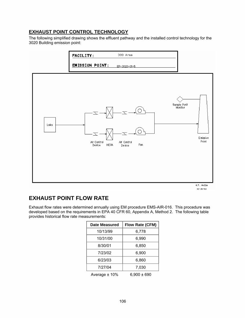
106
EXHAUST POINT CONTROL TECHNOLOGY The following simplified drawing shows the effluent pathway and the installed control technology for the 3020 Building emission point:
EXHAUST POINT FLOW RATE Exhaust flow rates were determined annually using EM procedure EMS-AIR-016. This procedure was developed based on the requirements in EPA 40 CFR 60, Appendix A, Method 2. The following table provides historical flow rate measurements:
Date Measured Flow Rate (CFM)10/13/99 6,778
10/31/00 6,990
8/30/01 6,850
7/23/02 6,900
6/23/03 6,860
7/27/04 7,030
Average ± 10% 6,900 ± 690
107
Note: Flow measurements were canceled from the annual frequency in the year 2005.
RECORD PARTICULATE SAMPLE SYSTEM DESCRIPTION The record particulate sampling system for emission point EP-3020-01-S was operated in conformance with 40 CFR 61, Subpart H and ANSI N13.1 (1969) requirements. See attached Stack Sampler Configuration Drawing H-3-307826.
SAMPLE EXTRACTION POINT The sample was extracted from the stack about 12 ft, 9 in. above the stack base. The sample probe is positioned 21 ft, 7 in. (11.77 equivalent diameters) downstream of the nearest flow disturbance and 4 ft, (2.18 equivalent diameters) from the top of the stack. The sample extraction point position meets the 8:2 (downstream: upstream) duct-diameter placement recommendation from ANSI (1969).
SAMPLE EXTRACTION PROBE A stainless steel, four-nozzle probe manufactured by Air Monitor Corporation was used to extract the sample. Each nozzle inlet has a 0.174-inch ID. See attached vendor-supplied drawings for details: W22192CA, Rev. 1.
SAMPLE TRANSPORT LINE The sample transport line is constructed of 1.12-in. ID stainless steel tubing. The line makes a 90º, 6-in. radius of curvature bend downward upon exiting the stack and terminates in a cabinet containing the collection filter, rotameter, and sample flow rate adjustment valve. The sample line upstream of the collector is insulated, heat traced, and electrically grounded. The sample line temperature is maintained above that of the stack gas to prevent condensation from forming in the sample line.
VACUUM AIR SAMPLE SYSTEM Vacuum air was supplied to the sample system by a single Rietschle carbon vane pump enclosed in a weatherproof housing for protection against the elements.
BATTELLE DRAWINGS NUMBER Stack Sampler Configuration EP-3020-01-S; Rev. 0 H-3-307826 The above drawing is not currently available to view electronically via this website. Electronic access to these drawings is available via the AutoManager® Software Program. Contact Shanna Abbott for AutoManager® access.
AIR MONITOR CORP. DRAWINGS NUMBER Flow-Sampler Probe with Temp Installation Details; Rev. 1 W22192CA Other drawings are provided by the vendor and are not available electronically at this time. For copies or questions regarding the drawings, contact Cheryl Duchsherer at 373-0594.
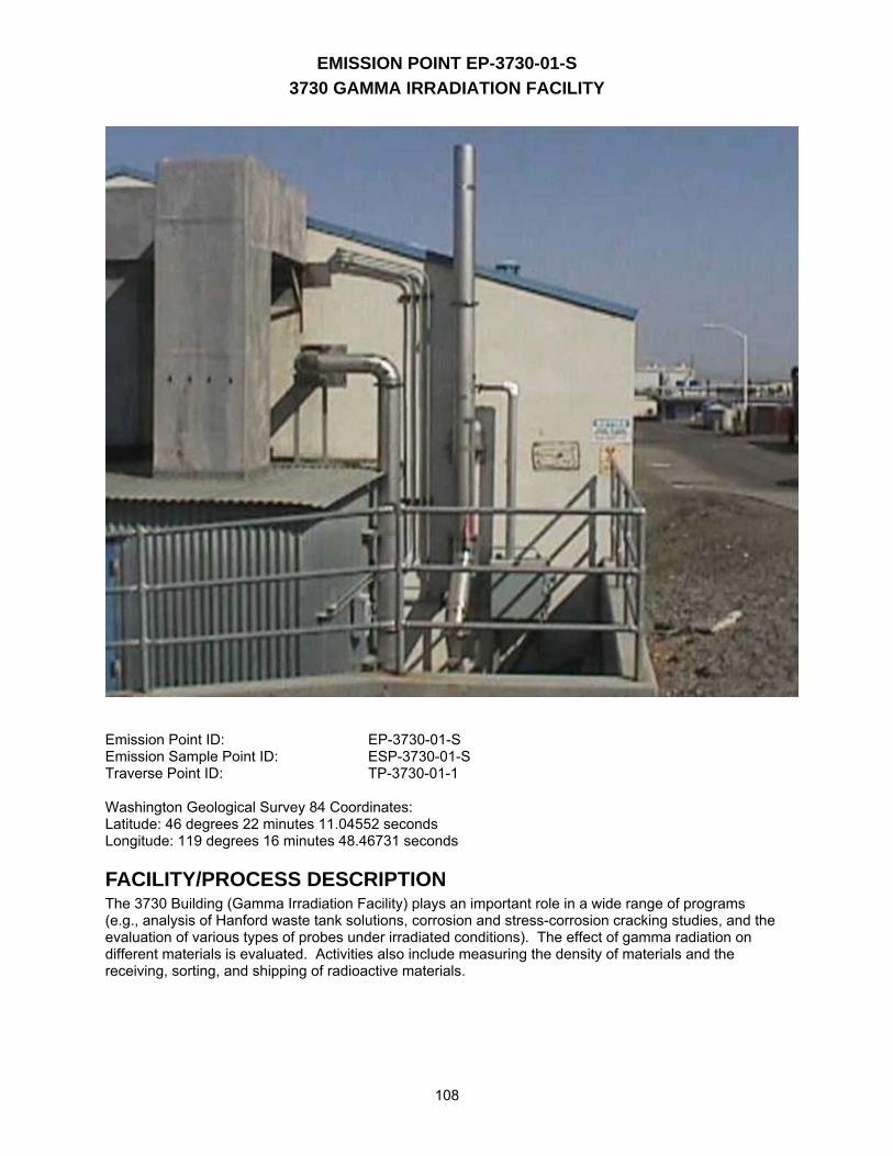
EMISSION POINT EP-3730-01-S 3730 GAMMA IRRADIATION FACILITY
108
Emission Point ID: EP-3730-01-S Emission Sample Point ID: ESP-3730-01-S Traverse Point ID: TP-3730-01-1 Washington Geological Survey 84 Coordinates: Latitude: 46 degrees 22 minutes 11.04552 seconds Longitude: 119 degrees 16 minutes 48.46731 seconds
FACILITY/PROCESS DESCRIPTION The 3730 Building (Gamma Irradiation Facility) plays an important role in a wide range of programs (e.g., analysis of Hanford waste tank solutions, corrosion and stress-corrosion cracking studies, and the evaluation of various types of probes under irradiated conditions). The effect of gamma radiation on different materials is evaluated. Activities also include measuring the density of materials and the receiving, sorting, and shipping of radioactive materials.
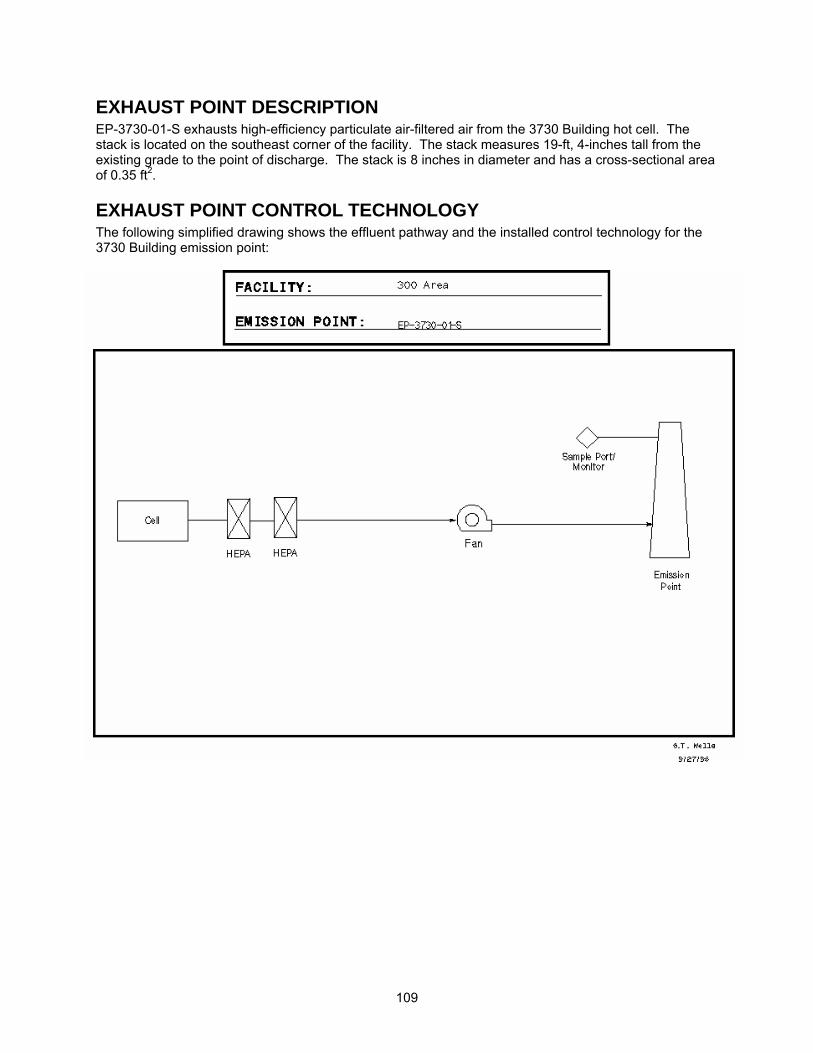
109
EXHAUST POINT DESCRIPTION EP-3730-01-S exhausts high-efficiency particulate air-filtered air from the 3730 Building hot cell. The stack is located on the southeast corner of the facility. The stack measures 19-ft, 4-inches tall from the existing grade to the point of discharge. The stack is 8 inches in diameter and has a cross-sectional area of 0.35 ft2.
EXHAUST POINT CONTROL TECHNOLOGY The following simplified drawing shows the effluent pathway and the installed control technology for the 3730 Building emission point:
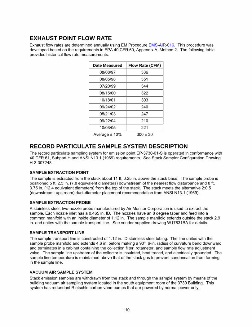
110
EXHAUST POINT FLOW RATE Exhaust flow rates are determined annually using EM Procedure EMS-AIR-016. This procedure was developed based on the requirements in EPA 40 CFR 60, Appendix A, Method 2. The following table provides historical flow rate measurements:
Date Measured Flow Rate (CFM)08/08/97 336
08/05/98 351
07/20/99 344
08/15/00 322
10/18/01 303
09/24/02 240
08/21/03 247
09/22/04 210 10/03/05 221
Average ± 10% 300 ± 30
RECORD PARTICULATE SAMPLE SYSTEM DESCRIPTION The record particulate sampling system for emission point EP-3730-01-S is operated in conformance with 40 CFR 61, Subpart H and ANSI N13.1 (1969) requirements. See Stack Sampler Configuration Drawing H-3-307248.
SAMPLE EXTRACTION POINT The sample is extracted from the stack about 11 ft, 0.25 in. above the stack base. The sample probe is positioned 5 ft, 2.5 in. (7.8 equivalent diameters) downstream of the nearest flow disturbance and 8 ft, 3.75 in. (12.4 equivalent diameters) from the top of the stack. The stack meets the alternative 2:0.5 (downstream: upstream) duct-diameter placement recommendation from ANSI N13.1 (1969).
SAMPLE EXTRACTION PROBE A stainless steel, two-nozzle probe manufactured by Air Monitor Corporation is used to extract the sample. Each nozzle inlet has a 0.465 in. ID. The nozzles have an 8 degree taper and feed into a common manifold with an inside diameter of 1.12 in. The sample manifold extends outside the stack 2.9 in. and unites with the sample transport line. See vendor-supplied drawing W17631BA for details.
SAMPLE TRANSPORT LINE The sample transport line is constructed of 1.12 in. ID stainless steel tubing. The line unites with the sample probe manifold and extends 4.6 in. before making a 90º, 6-in. radius of curvature bend downward and terminates in a cabinet containing the collection filter, rotameter, and sample flow rate adjustment valve. The sample line upstream of the collector is insulated, heat traced, and electrically grounded. The sample line temperature is maintained above that of the stack gas to prevent condensation from forming in the sample line.
VACUUM AIR SAMPLE SYSTEM Stack emission samples are withdrawn from the stack and through the sample system by means of the building vacuum air sampling system located in the south equipment room of the 3730 Building. This system has redundant Rietschle carbon vane pumps that are powered by normal power only.

111
BATTELLE DRAWINGS NUMBER Stack Sampler Configuration EP-3730-01-S; Rev. 0 H-3-307248 The above drawing is not currently available to view electronically via this website. Electronic access to these drawings is available via the AutoManager® Software Program. Contact Shanna Abbott for AutoManager® access.
AIR MONITOR CORP. DRAWINGS NUMBER Flo-Sampler/ 1 for 3730 Hot Cell Exhaust Duct; Rev. 3 W17631BA Other drawings are provided by the vendor and are not available electronically at this time. For copies or questions regarding the drawings, contact Cheryl Duchsherer at 373-0594.

113
Appendix F: Battelle Private Stack Sampler Systems
Appendix F contains facility, exhaust point, and sample extraction information for the following Battelle Private emission points: • EP-RTL-10-V • EP-RTL-11-V
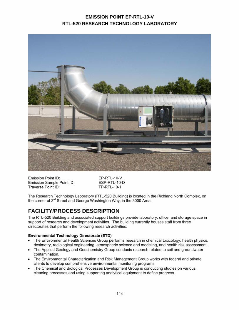
EMISSION POINT EP-RTL-10-V RTL-520 RESEARCH TECHNOLOGY LABORATORY
114
Emission Point ID: EP-RTL-10-V Emission Sample Point ID: ESP-RTL-10-D Traverse Point ID: TP-RTL-10-1 The Research Technology Laboratory (RTL-520 Building) is located in the Richland North Complex, on the corner of 3rd Street and George Washington Way, in the 3000 Area.
FACILITY/PROCESS DESCRIPTION The RTL-520 Building and associated support buildings provide laboratory, office, and storage space in support of research and development activities. The building currently houses staff from three directorates that perform the following research activities: Environmental Technology Directorate (ETD) • The Environmental Health Sciences Group performs research in chemical toxicology, health physics,
dosimetry, radiological engineering, atmospheric science and modeling, and health risk assessment. • The Applied Geology and Geochemistry Group conducts research related to soil and groundwater
contamination. • The Environmental Characterization and Risk Management Group works with federal and private
clients to develop comprehensive environmental monitoring programs. • The Chemical and Biological Processes Development Group is conducting studies on various
cleaning processes and using supporting analytical equipment to define progress.
EMISSION POINT EP-RTL-10-V RTL-520 RESEARCH TECHNOLOGY LABORATORY
115
Energy Science and Technology Directorate (ESTD)
• The Materials Chemistry and Surface Research Technical Group conducts R&D to develop coatings and to identify the application of coating technologies. Coating capabilities include polymer web coatings, sputtering coatings, large-optics coatings, e-beam evaporation coatings, and electospark coatings. Other capabilities are hydrothermal powder processing and microfabrication. The microfabrication capability includes laser micromachining, electrochemical machining, and electrodeposition.
Fundamental Science Directorate (FSD) • Environmental Dynamics & Simulation performs original research that is directed at understanding
reactions that occur at the solid-liquid interface of geologic materials. These include interfacial reactions controlling contaminant concentrations in soils and groundwater, linked geochemical-microbiological processes such as electron transfer reactions, and isotope geochemistry.
• The Chemical Structure and Dynamics Group develops advanced selective laser ionization methods for detection of metal and inorganic materials at ultra trace levels (FUA-RTL520-R3).
EXHAUST POINT DESCRIPTION EP-RTL-10-V is centrally located on the east end of the RTL-520 Building roof. The discharge point measures 26 feet, 0.5 inches above the existing ground level grade. The duct is 31.9 inches in diameter and has a cross-sectional area of 5.6 ft2.
EXHAUST POINT CONTROL TECHNOLOGY All exhaust gas passes through at least one high-efficiency particulate air (HEPA) filter before discharge to the environment. Refer to Stack Sampler Configuration drawing R-M-2004-1 for details.
EXHAUST POINT FLOW RATE Exhaust flow rates are determined annually using Effluent Management Procedure EMS-AIR-016. This procedure was developed based on the requirements in U.S. Environmental Protection Agency (EPA) 40 CFR 60, Appendix A, Method 2. The following table provides historical flow rate measurements:
Date Measured Flow Rate (CFM)
9/20/99 15,190
4/12/00 14,941
4/19/01 14,000
4/5/02 15,600
4/11/03 14,800
4/16/04 14,300 4/12/05 13,300
Average ± 10% 14,600 ± 1,500
RECORD PARTICULATE SAMPLE SYSTEM DESCRIPTION The record particulate sampling system for emission point EP-RTL-10-V is operated in conformance with 40 CFR 61, Subpart I and American National Standards Institute (ANSI) N13.1 (1969) requirements. See Stack Sampler Configuration Drawing R-M-2004-1.
SAMPLE EXTRACTION POINT The record sample probe nozzle tips are positioned in the horizontal duct 23 ft, 11.4 inches (9.01 equivalent diameters) downstream of the nearest flow disturbance and 5 ft, 5.38 inches (2.05 equivalent
EMISSION POINT EP-RTL-10-V RTL-520 RESEARCH TECHNOLOGY LABORATORY
116
diameters) upstream from the nearest flow disturbance. The sample extraction point position meets the 8:2 (downstream: upstream) duct-diameter placement recommendation from ANSI N13.1 (1969).
SAMPLE EXTRACTION PROBE A stainless steel, five-nozzle probe manufactured by Air Monitor Corporation is used to extract the sample from the duct. Each nozzle inlet has a 0.185-in. inside diameter (ID). The five sample nozzles are tapered and feed into a common 1.12-in. ID manifold that extends horizontally across the center of the duct. See vendor-supplied drawings for details: W36670AA, W36670BA, W36670BB, W36670BC and W36670BD.
SAMPLE TRANSPORT LINE The sample transport line is constructed of 1.12-in. ID stainless steel tubing. The sample transport line extends 10 inches outside the duct and terminates in a cabinet containing the collection filter, rotameter, and sample flow rate adjustment valve. The sample line upstream of the collector is insulated, heat traced, and electrically grounded. The sample line temperature is maintained above that of the stack gas to prevent condensation from forming in the sample line. Stack emission samples are withdrawn from the stack and through the sample system by means of the building vacuum air sampling system located in East Service Corridor of the RTL-520 Building. This system has redundant carbon vane vacuum pumps that are powered by normal and emergency power.
BATTELLE DRAWINGS NUMBER MECHANICAL EXHAUST FAN DEMOLITION PLAN; Rev.0 R-M-1947-1 MECHANICAL EXHAUST FAN PLAN; Rev.2 R-M-1947-2 MECHANICAL EXHAUST FAN SECTION AND DETAILS; Rev.0 R-M-1947-3 STACK SAMPLER CONFIGURATION EP-RTL-10-V; Rev.1 R-M-2004-1 AIR SAMPLE STATION INSTRUMENT CABINET ASSEMBLY; Rev.8 H-3-70282-1 STACK SAMPLE FILTER HOLDER INLET; Rev.1 H-3-70447-1 STACK SAMPLE FILTER HOLDER OUTLET; Rev.0 H-3-70570-1 Historical Stack Sampler Configuration before RTL Modification (AIR 00-410) STACK SAMPLER CONFIGURATION EP-RTL-02-S; Rev.0 R-M-1925-2
STACK SAMPLER CONFIGURATION EP-RTL-03-S; Rev.0 R-M-1925-3
STACK SAMPLER CONFIGURATION EP-RTL-04-S; Rev.0 R-M-1925-4
STACK SAMPLER CONFIGURATION EP-RTL-05-S; Rev.0 R-M-1925-5
STACK SAMPLER CONFIGURATION EP-RTL-06-S; Rev.0 R-M-1925-6
The above drawings are not currently available to view electronically via this website. Electronic access to these drawings is available via the AutoManager® Software Program. Contact Shanna Abbott for AutoManager® access. AIR MONITOR CORPORATION DRAWINGS NUMBER SAMPLR−probe THREADED NOZZLE; Rev.0 W36670AA SAMPLR−probe TOP ASSEMBLY; Rev. 1 W36670BA SAMPLR−probe SAMPLE MANIFOLD; Rev. 0 W36670BB SAMPLR−probe MOUNTING PLATE & GASKET; Rev. 1 W36670BC SAMPLR−probe RADIUSED END PLUG; Rev. 0 W36670BD Other drawings are provided by the vendor and are not available electronically at this time. For copies or questions regarding the drawings, contact Cheryl Duchsherer at 373-0594.
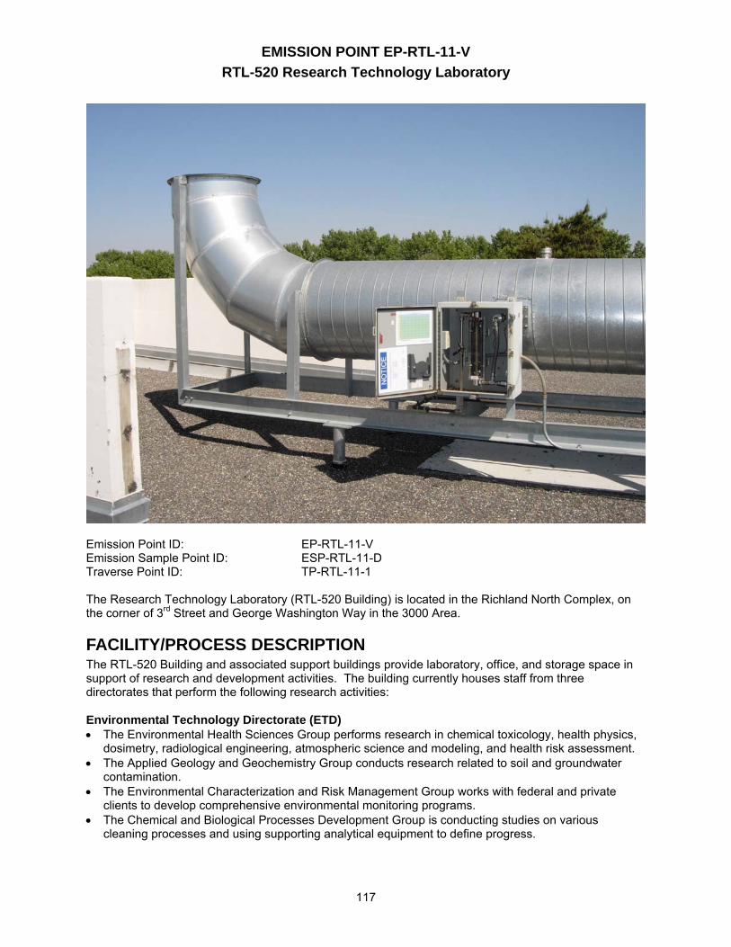
EMISSION POINT EP-RTL-11-V RTL-520 Research Technology Laboratory
117
Emission Point ID: EP-RTL-11-V Emission Sample Point ID: ESP-RTL-11-D Traverse Point ID: TP-RTL-11-1 The Research Technology Laboratory (RTL-520 Building) is located in the Richland North Complex, on the corner of 3rd Street and George Washington Way in the 3000 Area.
FACILITY/PROCESS DESCRIPTION The RTL-520 Building and associated support buildings provide laboratory, office, and storage space in support of research and development activities. The building currently houses staff from three directorates that perform the following research activities: Environmental Technology Directorate (ETD) • The Environmental Health Sciences Group performs research in chemical toxicology, health physics,
dosimetry, radiological engineering, atmospheric science and modeling, and health risk assessment. • The Applied Geology and Geochemistry Group conducts research related to soil and groundwater
contamination. • The Environmental Characterization and Risk Management Group works with federal and private
clients to develop comprehensive environmental monitoring programs. • The Chemical and Biological Processes Development Group is conducting studies on various
cleaning processes and using supporting analytical equipment to define progress.
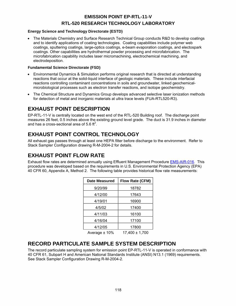
EMISSION POINT EP-RTL-11-V RTL-520 RESEARCH TECHNOLOGY LABORATORY
118
Energy Science and Technology Directorate (ESTD)
• The Materials Chemistry and Surface Research Technical Group conducts R&D to develop coatings and to identify applications of coating technologies. Coating capabilities include polymer web coatings, sputtering coatings, large-optics coatings, e-beam evaporation coatings, and electospark coatings. Other capabilities are hydrothermal powder processing and microfabrication. The microfabrication capability includes laser micromachining, electrochemical machining, and electrodeposition.
Fundamental Science Directorate (FSD) • Environmental Dynamics & Simulation performs original research that is directed at understanding
reactions that occur at the solid-liquid interface of geologic materials. These include interfacial reactions controlling contaminant concentrations in soils and groundwater, linked geochemical-microbiological processes such as electron transfer reactions, and isotope geochemistry.
• The Chemical Structure and Dynamics Group develops advanced selective laser ionization methods for detection of metal and inorganic materials at ultra trace levels (FUA-RTL520-R3).
EXHAUST POINT DESCRIPTION EP-RTL-11-V is centrally located on the west end of the RTL-520 Building roof. The discharge point measures 26 feet, 0.5 inches above the existing ground level grade. The duct is 31.9 inches in diameter and has a cross-sectional area of 5.6 ft2.
EXHAUST POINT CONTROL TECHNOLOGY All exhaust gas passes through at least one HEPA filter before discharge to the environment. Refer to Stack Sampler Configuration drawing R-M-2004-2 for details.
EXHAUST POINT FLOW RATE Exhaust flow rates are determined annually using Effluent Management Procedure EMS-AIR-016. This procedure was developed based on the requirements in U.S. Environmental Protection Agency (EPA) 40 CFR 60, Appendix A, Method 2. The following table provides historical flow rate measurements:
Date Measured Flow Rate (CFM)
9/20/99 18782
4/12/00 17643
4/19/01 16900
4/5/02 17400
4/11/03 16100
4/16/04 17100
4/12/05 17800 Average ± 10% 17,400 ± 1,700
RECORD PARTICULATE SAMPLE SYSTEM DESCRIPTION The record particulate sampling system for emission point EP-RTL-11-V is operated in conformance with 40 CFR 61, Subpart H and American National Standards Institute (ANSI) N13.1 (1969) requirements. See Stack Sampler Configuration Drawing R-M-2004-2.
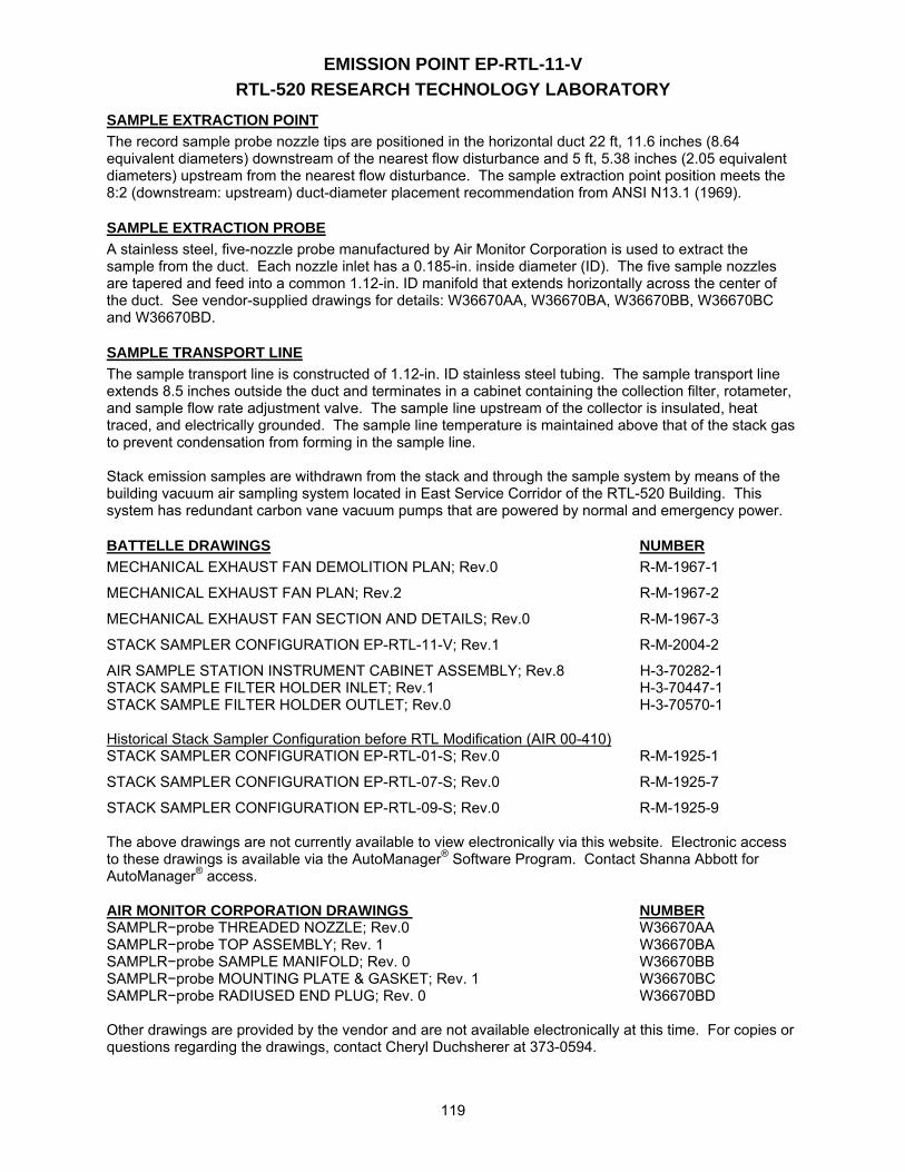
EMISSION POINT EP-RTL-11-V RTL-520 RESEARCH TECHNOLOGY LABORATORY
119
SAMPLE EXTRACTION POINT The record sample probe nozzle tips are positioned in the horizontal duct 22 ft, 11.6 inches (8.64 equivalent diameters) downstream of the nearest flow disturbance and 5 ft, 5.38 inches (2.05 equivalent diameters) upstream from the nearest flow disturbance. The sample extraction point position meets the 8:2 (downstream: upstream) duct-diameter placement recommendation from ANSI N13.1 (1969).
SAMPLE EXTRACTION PROBE A stainless steel, five-nozzle probe manufactured by Air Monitor Corporation is used to extract the sample from the duct. Each nozzle inlet has a 0.185-in. inside diameter (ID). The five sample nozzles are tapered and feed into a common 1.12-in. ID manifold that extends horizontally across the center of the duct. See vendor-supplied drawings for details: W36670AA, W36670BA, W36670BB, W36670BC and W36670BD.
SAMPLE TRANSPORT LINE The sample transport line is constructed of 1.12-in. ID stainless steel tubing. The sample transport line extends 8.5 inches outside the duct and terminates in a cabinet containing the collection filter, rotameter, and sample flow rate adjustment valve. The sample line upstream of the collector is insulated, heat traced, and electrically grounded. The sample line temperature is maintained above that of the stack gas to prevent condensation from forming in the sample line. Stack emission samples are withdrawn from the stack and through the sample system by means of the building vacuum air sampling system located in East Service Corridor of the RTL-520 Building. This system has redundant carbon vane vacuum pumps that are powered by normal and emergency power.
BATTELLE DRAWINGS NUMBER MECHANICAL EXHAUST FAN DEMOLITION PLAN; Rev.0 R-M-1967-1
MECHANICAL EXHAUST FAN PLAN; Rev.2 R-M-1967-2
MECHANICAL EXHAUST FAN SECTION AND DETAILS; Rev.0 R-M-1967-3
STACK SAMPLER CONFIGURATION EP-RTL-11-V; Rev.1 R-M-2004-2
AIR SAMPLE STATION INSTRUMENT CABINET ASSEMBLY; Rev.8 H-3-70282-1 STACK SAMPLE FILTER HOLDER INLET; Rev.1 H-3-70447-1 STACK SAMPLE FILTER HOLDER OUTLET; Rev.0 H-3-70570-1 Historical Stack Sampler Configuration before RTL Modification (AIR 00-410) STACK SAMPLER CONFIGURATION EP-RTL-01-S; Rev.0 R-M-1925-1
STACK SAMPLER CONFIGURATION EP-RTL-07-S; Rev.0 R-M-1925-7
STACK SAMPLER CONFIGURATION EP-RTL-09-S; Rev.0 R-M-1925-9 The above drawings are not currently available to view electronically via this website. Electronic access to these drawings is available via the AutoManager® Software Program. Contact Shanna Abbott for AutoManager® access. AIR MONITOR CORPORATION DRAWINGS NUMBER SAMPLR−probe THREADED NOZZLE; Rev.0 W36670AA SAMPLR−probe TOP ASSEMBLY; Rev. 1 W36670BA SAMPLR−probe SAMPLE MANIFOLD; Rev. 0 W36670BB SAMPLR−probe MOUNTING PLATE & GASKET; Rev. 1 W36670BC SAMPLR−probe RADIUSED END PLUG; Rev. 0 W36670BD Other drawings are provided by the vendor and are not available electronically at this time. For copies or questions regarding the drawings, contact Cheryl Duchsherer at 373-0594.