Embed Size (px)
Citation preview

3 XI November 2015

www.ijraset.com Volume 3 Issue XI, November 2015 IC Value: 13.98 ISSN: 2321-9653
International Journal for Research in Applied Science & Engineering Technology (IJRASET)
©IJRASET 2015: All Rights are Reserved
356
A Modern Design of Torque Ripples Reduction in BLDC Drive for Electric Vehicle Application
Nazia Shaik 1, G.Sri Harsha 2, Rushi Santosh Singh T 3
1 P.G Student, 2 Asst. professor, 3 Head of the Dept , EEE Department, M.V.R. College of Engineering & Technology, Paritala, AP, India.
Abstract: - BLDC motors are one of the motor type’s fast gaining the interest of the researchers. This motor attracts to a great extent concern due to its better speed, high dynamic response, high efficiency, long operating life, noiseless operation and power density, compactness, high torque potential for steep slope or road conditions, high reliability, robustness for electric vehicle and offers a reasonable cost. This paper presents a minimization of torque ripples in brushless DC (BLDC) drive by using Hysteresis Current Limiting technique to extend the lifetime of batteries per charge in electric vehicle applications. In the conventional current control method the current is still drawn from the batteries even when the motor is turned off which results it reduces the life time of the battery by continuous leakage current from the battery. To avoid that leakage current it is fed to zero crossing detector here the leakage current is controlled by using Hysteresis comparator but it produces high switching frequency which produces ripples in torque. In this technique only current control is possible but the ripples are caused by hysteresis control and inverter switching intervals. The proposed method controls the inverter switching intervals and high switching frequency by using DC to DC Converter which minimizes the Torque Ripples. The simulation and control of the BLDC motor is done by using the MATLAB/SIMULINK. Index Terms: - Brushless DC (BLDC) motor, Converter (Buck), Current Source Inverter (CSI), Electric vehicle, Hysteresis controller, Step down converter(Buck) Zero Crossing Detector.
I. INTRODUCTION
Now a day’s Electric Vehicle (EV) is a rising technology in the modern world because of the fact that it mitigates environmental pollutions and at the same time controls large amount of fossils fuel usage, and efficiency of the vehicles. Battery-powered electric vehicles are one of the solutions to reduce the fuel consumption to tackle the energy disaster and global warming. On the other hand, the high initial cost, short driving range, long charging (refueling) time, and reduced passenger and cargo space have proved the limitation of battery-powered EVs. The efficiency of the battery is very important, because the electric motor uses the excess power of the engine to charge battery. If the engine produces more power than the driver then it provides additional power to assist the driving. BLDC drives are widely used for driving purpose. Actually BLDC motor is one of the types of synchronous motor which works on the principle of Faradays Law of Electromagnetic Conversion. It consists of a permanent magnet with a trapezoidal Back EMF waveform shape. The main consideration of BLDC motors does not uses mechanical commutator and carbon brushes for commutation instead of that it uses electronic commutator which reduces sparks, wear and tear problems with no maintenance because they are electronically commutated. Here current commutation is done by solid state switches. Brushless DC (BLDC) motors are commonly used for several industrial applications because of their small in size, high torque and high efficiency , so these are employed in the industries like Industrial Automation equipment and Instrumentation, Appliances, Automotive, Aircraft, Consumer, Medical. BLDC motors are available many different power ratings, which differ from very small motor as used in hard disk drives to large motor used in electric vehicles.
II. CONSTRUCTION OF BLDC MOTOR
The construction of a BLDC motor is similar to the synchronous motor with the armature winding on stator but whose field winding on rotor is replaced by permanent magnets on rotor and the commutation of currents in stator phases is carried out electronically in synchronism with rotor movement. Permanent magnets have grades of an alloy of aluminum, nickel, cobalt and iron which has very large hysteresis property. The two parts of motor are stator (stationary part) and rotor (rotating part) in which rotor rotates and

www.ijraset.com Volume 3 Issue XI, November 2015 IC Value: 13.98 ISSN: 2321-9653
International Journal for Research in Applied Science & Engineering Technology (IJRASET)
©IJRASET 2015: All Rights are Reserved
357
generates magnetic field at the same frequency, hence it eliminates the slip. BLDC motors have lifelong excitation from permanent magnets mounted on rotor surface.
Fig 1. SPM Rotor and IPM Rotors
There are two basic rotor designs surface permanent magnet rotor design and interior permanent magnet rotor design as shown in Figure 1. For the surface permanent magnet rotor design, the winding are located in the core of the motor. The rotor magnets surround the stator windings and acts as an insulator, reducing the rate of heat dissipation from the motor. This design operates at lower duty cycles or at lower rated current and it is used in low speed applications. The benefit of this design is relatively low cogging torque. For the interior permanent magnet rotor design, the stator winding surrounded by the rotor and is fixed at motor housing. The advantage of the design is the ability to dissipate heat thus directly impacts its ability to generate torque and its lower inertia and these are used in high speed applications. Stator having a 3-ϕ windings and the no of stator slots is chosen depending on the rotor poles, winding arrangement, phase number. A fractional slots/pole design is preferred to reducing the cogging torque. The winding slots are built into the stator and rotating magnetic field is provided by the current polarity changes in the slot windings. The change of current polarity must be in accordance to the rotor magnetic field, which requires the position of the rotor. Hall Effect sensors are fixed on the stator to provide this information. Solid state switches are used for current commutation which eliminates the need of brushes.
A. Operation of BLDC The fundamental working principle of BLDC motor is same as that of a conventional DC Motor with the permanent magnets placed in the rotor and coils in the stator. Having the armature windings on stator helps the conduction of heat from the windings. As the winding is absent on rotor, the rotor copper losses are negligible. The coil windings are electrically separate from each other which allows them to turn on and off in a sequence that creates a rotating magnetic field.
Fig 2. BLDC motor cross section and phase energizing sequence
The rotor position is to be determined so that excitation of the stator field always leads to the generation of torque. The rotor is not

www.ijraset.com Volume 3 Issue XI, November 2015 IC Value: 13.98 ISSN: 2321-9653
International Journal for Research in Applied Science & Engineering Technology (IJRASET)
©IJRASET 2015: All Rights are Reserved
358
electrically connected to the stator thus preventing arcing phenomena which cause carbon to be produce hence making insulation failure. Here the commutation instants are determined by the rotor position and the position of the rotor is detected either by position sensors or by sensor less techniques. For this mostly we are using two types of sensors they are Hall Effect sensors and Optical position sensors. These sensors are placed on shaft. The signals from these sensors that generally used in BLDC motor drive to energize the appropriate stator windings. The permanent magnets used in BLDC motor it helps to keep the inertia low. The back e.m.f amplitude of the BLDC is proportional to the rotor speed.
TABLE I: Hall Signals and Phase Sequence
Switching sequence
Sequence. No
Position Sensors
Switch closed
Phase current
H1
H2
H3
A
B
C
00-600 0 1 0 0 Q1 Q4 + - Off 600-1200 1 1 1 0 Q1 Q6 + Off -
1200-1800 2 0 1 0 Q3 Q6 Off + -
1800-2400 3 0 1 1 Q3 Q2 - + Off 2400-3000 4 0 0 1 Q5 Q2 - off +
3000-3600 5 1 0 1 Q5 Q4 off - +
The air gap flux-density wave form is essentially square wave, w.r.t the rotor position. Because of firing the back e.m.f waveform takes on trapezoidal shape.
Fig 3. Three phase Hall Signels and Back E.M.F wave forms

www.ijraset.com Volume 3 Issue XI, November 2015 IC Value: 13.98 ISSN: 2321-9653
International Journal for Research in Applied Science & Engineering Technology (IJRASET)
©IJRASET 2015: All Rights are Reserved
359
The back e.m.f induced in each phase are similar in shape and are displaced by 1200 w.r.t each other. By injecting rectangular current pulses in each phase that coincides with the crest of the back e.m.f wave form in that phase, it is possible to obtain almost constant torque from the BLDC motor. The amplitude of the phase back e.m.f is proportional to the rotor speed, which is given by
E = kϕ ωm (1) Where, k = a constant depends on the no.of turns in each phase; ϕ = permanent magnate flux ;ωm = mechanical speed. During any 1200 interval, the instantaneous power is converted from electrical form to mechanical form, it is given by
Po = ωm Te = 2 EI (2)
So the out put torque can be written as
Te = 2 kϕ I = Te = kt I (3)
Where, kt = torque constant, Te = out put toque
A BLDC motor mathematical equations can be derived similar to DC machines where there are two equivalent circuits, i.e. electrical and mechanical equations Figure 4 shows the basic blocks of BLDC motor that contains three phase stator circuit and mechanical part. Applying Kirchhoff’s voltage law for the three phase stator loop winding circuit yields.
Fig 4. 3-ϕ Brushless DC machine equivalent circuit and mechanical model.
)4(ac
acb
aba
aaaa edtdiM
dtdiM
dtdiLRiv
)5(bc
baa
bcb
bbbb edtdiM
dtdiM
dtdiLRiv
)6(cb
cba
cac
cccc edtdiM
dtdiM
dtdiLRiv
Where, va = instantaneous phase voltage
ia = instantaneous phase current
ea = instantaneous phase back e.m.f voltage
Ra = phase-a resistance
La= phase-a inductance
M= mutual inductance
www.ijraset.com Volume 3 Issue XI, November 2015 IC Value: 13.98 ISSN: 2321-9653
International Journal for Research in Applied Science & Engineering Technology (IJRASET)
©IJRASET 2015: All Rights are Reserved
360
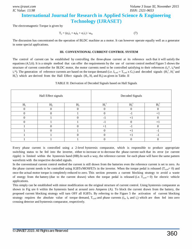
The electromagnetic Torque is given by
Te = (eaia + ebib + ecic) / ωm (7)
The discussion has concentrated on the operation of BLDC machine as a motor. It can however operate equally well as a generator in some special applications.
III. CONVENTIONAL CURRENT CONTROL SYSTEM
The control of current can be established by controlling the three-phase current at its reference such that it will satisfy the equations (4,5,6). It is a simple method that can offer the requirements by the use of current control method Figure 5 shows the structure of current controller for BLDC motor, the motor currents need to be controlled satisfying to their references (ia*, ib*and ic*). The generation of reference currents are based on the torque demand (i.e. Ie,ref = Te,ref x G1) and decoded signals (H1
l, H2l and
H3l) which are derived from the Hall Effect signals (H1, H2 and H3) as given in Table. II
TABLE II: Derivation of Decoded Signals based on Hall Signals
Hall Effect signals
Decoded Signals
H1 H2 H3 H1l H2
l H3l
0 0 0 0 0 0 0 0 1 0 -1 +1 0 1 0 -1 +1 0 0 1 1 -1 0 +1 1 0 0 +1 -1 0 1 0 1 0 +1 -1 1 1 0 0 +1 -1 1 1 1 0 0 0
Every phase current is controlled using a 2-level hysteresis comparator, which is responsible to produce appropriate switching status to be fed into the inverter, either to increase or to decrease the phase current such that its error (or current ripple) is limited within the hysteresis band (HB).In such a way, the reference current for each phase will have the same pattern waveform with the respective decoded signals. In the conventional current control method the current is still drawn from the batteries even the reference current is set to zero. As the phase current needs to be controlled using IGBTs/MOSFETs in the inverter. When the torque pedal is released (Te,ref= 0) and once the actual motor torque is completely reduced to zero. This section presents a current blocking strategy to avoid a waste of energy from the battery (due to the current drawn) when the torque pedal is released (i.e. Te,ref = 0) for electric vehicle applications. This simply can be established with minor modification on the original structure of current control. Using hysteresis comparator as shown in Fig ure 6 within the hysteresis band at around zero Amperes (A). To block the current drawn from the battery, the proposed current blocking strategy will turn OFF all IGBTs. By referring to the Figure 5 the activation of current blocking strategy requires the absolute value of torque demand, Te,ref and phase currents (ia, ib and ic) which are then fed into zero crossing detector and hysteresis comparator, respectively.

www.ijraset.com Volume 3 Issue XI, November 2015 IC Value: 13.98 ISSN: 2321-9653
International Journal for Research in Applied Science & Engineering Technology (IJRASET)
©IJRASET 2015: All Rights are Reserved
361
Fig 5. Conventional current blocking strategy based on hysteresis comparator
The operation to switch OFF all IGBTs/MOSFETs in current source inverter will carry out if the torque production, Te and torque demand, Te, ref decreases to zero. For clearer picture, the condition of the activation is illustrated in Figure 6. Otherwise, usual switching operation to keep the current (or torque) to be regulated within the hysteresis band will perform.
Fig 6. Blocking Strategy is Activated if Te and Te,ref Decrease to zero
IV. BLOCK DIAGRAM COMPONENTS
A. Current Limiter In this paper, for current limiting purpose a current controller is must. So hysteresis controller is employed. Hysteresis control is one of the uncomplicated closed-loop control schemes. A reference sine wave current is compared with the actual phase current. When the current exceeds a given hysteresis band, the upper switch in the inverter bridge is turned off and the lower switch is turned on, and the current starts to decay. As the current crosses the lower band limit, the lower switch is turned off and the upper switch is turned on. The actual current is forced to track the sine reference within the hysteresis band by back and forth (or bang-bang) switching of the upper and lower switches. The inverter then essentially becomes a current source with peak-to-peak current ripple, which is restricted within the hysteresis band. In hysteresis control, the value of the controlled variable is forced to stay within certain limits around its reference value. By comparing with PWM technique, hysteresis current controller is preferred, considering its performance, fast reaction maximum current limit and insensible to load parameter variations. Due to lack of coordination among individual hysteresis controllers of three phases, very high switching frequency at lower modulation index may happen [8]. The disadvantage of the hysteresis band control technique are the high and uncontrolled switching. frequencies when a narrow hysteresis band is used and large ripples when the hysteresis band is wider [9]. The uncontrolled switching frequency makes it difficult to filter the acoustic and electromagnetic noise. The switching method used here is the soft chopping method in which only the upper switch is turned on and off while the lower switch is left on. This method

www.ijraset.com Volume 3 Issue XI, November 2015 IC Value: 13.98 ISSN: 2321-9653
International Journal for Research in Applied Science & Engineering Technology (IJRASET)
©IJRASET 2015: All Rights are Reserved
362
produces less torque ripple and less switching losses than the hard chopping method. Only current control is implemented here. The reason is that if position control is to be implemented in the same way as the torque and the position control, it would only be possible by constantly reversing the rotor speed so that the rotor angle would stay within the hysteresis band.
B. A.C to D.C Converter A.C to D.C Converter (Rectifier) is a electronic device, it converts alternating current to direct current (A.C-D.C), which flows only in single direction. Several applications of rectifiers used as a power supplies for television and computer equipment, radios, where a constant DC current (as would be produced by a battery) is necessary. In these applications the output of the rectifier is curved by an electronic filter (usually a capacitor) to generate a steady current.
C. Step down Converter
Fig 7. DC /D.C (buck) converter
The fundamental operation of the step down converter has the current in an inductor limited by two switches (generally a transistor and a diode). A buck converter is also called as a voltage step down and current step up converter. In this paper, the buck converter is used for voltage step down purpose of rectified D.C. the voltage is being controlled depending on the duty ratio (D). The gate signals are generated by using current speed wave forms of the motor. This controlled voltage is fed to the battery.
Output voltage of buck converter
V o = D V in (8)
D. Current Source Inverter An inverter is an electronic device that changes direct current (DC) to alternating current (AC). The input voltage, output voltage, frequency, and overall power handling depend on the design of the particular device. The converter is a three phase DC to AC converter and it consists of six solid state semiconductor switches as shown inure 8. Mosfets and IGBT are the most common types of switches used. For lower power application, MOSFETs are preferred over IGBTs. The power electronic converter is essential to operate the BLDC machine. Current commutation is done by a six-step inverter. The three phase BLDC motor is operating in a two phases-on fashion which means the two phases that produce the highest torque are energized while the third phase is off, see Figure 2. The two phases are energized depends on the rotor position. Hall Effect position sensors are most frequently used.
The inverter is responsible for both the Electronic commutation and current regulation. The conduction of every phase winding is determined by the rotor position where the position can be known from hall effect sensors that provides three digit output that changes every 60 degree (electrical degrees).The generation of three digitized outputs (i.e. H1,H2 and H3) from the sensor according to the rotor position can be also described in Table 2. The inverter must be capable of applying positive, negative and zero voltage across the motor phase terminals. Each drive phase consists of one motor terminal driven positive, one motor terminal driven negative, and one motor terminal floating (zero) [6].

www.ijraset.com Volume 3 Issue XI, November 2015 IC Value: 13.98 ISSN: 2321-9653
International Journal for Research in Applied Science & Engineering Technology (IJRASET)
©IJRASET 2015: All Rights are Reserved
363
Fig 8. Three-Phase DC /AC inverter.
V. PROPOSED TORQUE RIPPLE MINIMIZATION TECHNIQUE
In the conventional current control strategy only current will be controlled, with high ripples in torque. The Torque ripple minimization scheme is extended to BLDC motor drives to reduce the Torque Ripples. The electro-magnetic torque and the stator flux linkage amplitude of the BLDC motor under 2-phase conduction mode can be controlled simultaneously. Here we are going to reduce the ripples in torque by using Torque ripple minimization scheme. BLDC drive has a drawback of high torque pulsation. Mostly it is caused by two-components one is ripple torque and another one is commutation torque. The basic components of ripple torque are motor related and inverter related. Motor related components are produced by the non-idealities in the back e.m.f wave forms. Here Motor relates cogging torque, inverter relates ripple torque. Cogging torque produced by variation of reluctance caused by the stator slot openings as rotor rotates. Cogging torque can be minimized by skewing and by choosing a fractional slot/pole motor design. Ripple torque is a consequence of the interaction of the armature currents with the machine back e.m.f wave forms.
Fig 9. Block diagram of proposed system
The inverter related ripple torque components departure from the ideal rectangular current profiles due to finite inductance. The inverter related ripple torque is caused by the Hysteresis current limiter because which generates high switching frequency ripple.

www.ijraset.com Volume 3 Issue XI, November 2015 IC Value: 13.98 ISSN: 2321-9653
International Journal for Research in Applied Science & Engineering Technology (IJRASET)
©IJRASET 2015: All Rights are Reserved
364
This high frequency ripple is caused by resultant ripple in phase current. The back e.m.f related component has high frequency; it is 6 times of the electrical frequency, corresponding to the 6 conduction instants in every cycle. At low speeds they can affect the performance of the drive, but at high speeds it is not a problem as it is filtered out by load inertia. This high frequency torque ripple is minimized by limiting the current and rotor position. The second component of inverter related torque ripple is commutation torque ripple, it occurs at every commutation interval. The torque ripple generates some of the currents at ON/OFF position almost never constant during the switching interval. Here the current is commutated from phase-B to phase-C. The rate at which the current builds up in phase-C is greater than the rate at which decays in phase-B, which results in current ripple in phase-A and a resultant ripple in torque production. This torque ripple depends on rotor speed and source voltage. This commutation ripple component is reduced by using current sensor in each phase. Here D.C/D.C converter controls the source voltage, BLDC motor current and speed (ωm).
Fig 10 . Torque Ripple Wave Forms
Actual speed (ω) compared with reference speed (ω*) and is controlled using PI controller. The PWM controller generates the switching pulses to the buck converter, which controls the source voltage. In conventional current control only current control is possible, but having large torque ripple as shown in above Figure 10 (ripple is nearly 1.4 N-m), so the torque ripple is minimized to 1.4 N-m to 0.12 N-m.
VI. SIMULATION CIRCUITS AND RESULTS
Fig 11. Simulink Block Diagram of Overall System
The above Figure 11 refers that overall simulation diagram of proposed Torque ripple minimization scheme. It contains a.c source, d.c/d.c converter, inverter and BLDC drive.

www.ijraset.com Volume 3 Issue XI, November 2015 IC Value: 13.98 ISSN: 2321-9653
International Journal for Research in Applied Science & Engineering Technology (IJRASET)
©IJRASET 2015: All Rights are Reserved
365
Fig 12. Simulink Circuit of Controlling Circuit
The above Figure 12 refers the simulation diagram of inverter controlling system. It controls torque and speed by controlling current and rotor position.
Fig 13. Hall Signals
The above Figure 13 refers that the hall signals are generated by the leakage flux at the appropriate rotor positions
Fig 14. Back E.M.F Wave Forms
The above Figure 14 refers Back E.M.F wave forms. Which are displaced by 1200 w.r.t each other in a 3-phase machine.
Fig 15. Motor Stator Currents
. The above Figure 15 refers 3-phase stator currents and the current error ripple is limited within the predefined band gap.

www.ijraset.com Volume 3 Issue XI, November 2015 IC Value: 13.98 ISSN: 2321-9653
International Journal for Research in Applied Science & Engineering Technology (IJRASET)
©IJRASET 2015: All Rights are Reserved
366
Fig 16. Blocking strategy Motor leakage Currents Above Figure 16 waveforms refers leakage currents of the motor. Current ripple is reduced small amount compared to current control 1A to 0.8 A.
Fig 17 (a). Torque wave forms
The above Figure 17(a) refers reduced ripple torque waveforms.
Fig 17(b). Minimized Torque Ripple Wave Form
The above Figure 17(b) refers to minimized torque ripple waveforms (ripple is minimized from 1.4 N-m to 0.12 N-m).
Above Figure 17(a) refers torque wave forms; these are in positive and negative. It can be observed as the speed and torque decreases (during motor braking) the frequency of the current waveforms decreases and as the speed and torque increase (during motor acceleration) the frequency of the current waveforms increases. By the operation of a BLDC motor it can however work as generator. The polarity of Torque can be reversed by simply reversing the polarity of phase current waveforms w.r.t back e.m.f. waveforms. In regenerative breaking it is used an advantage, in vehicle population. For example special arrangements are needed in the power converter to allow the energy returned by the machine, as conventional diode bridge rectifiers are unable to feed back to the A.C. supply. In automobile applications this situation is considerably simplified by using the battery as a source.
www.ijraset.com Volume 3 Issue XI, November 2015 IC Value: 13.98 ISSN: 2321-9653
International Journal for Research in Applied Science & Engineering Technology (IJRASET)
©IJRASET 2015: All Rights are Reserved
367
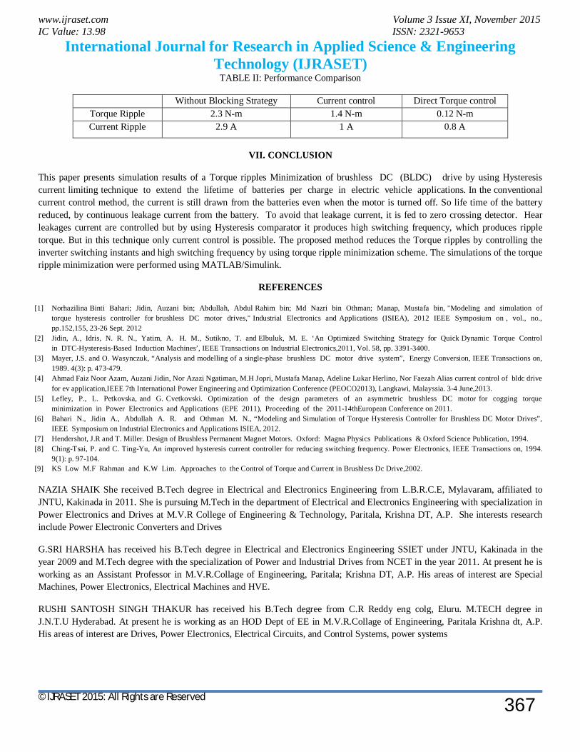
TABLE II: Performance Comparison
Without Blocking Strategy Current control Direct Torque control Torque Ripple 2.3 N-m 1.4 N-m 0.12 N-m Current Ripple 2.9 A 1 A 0.8 A
VII. CONCLUSION
This paper presents simulation results of a Torque ripples Minimization of brushless DC (BLDC) drive by using Hysteresis current limiting technique to extend the lifetime of batteries per charge in electric vehicle applications. In the conventional current control method, the current is still drawn from the batteries even when the motor is turned off. So life time of the battery reduced, by continuous leakage current from the battery. To avoid that leakage current, it is fed to zero crossing detector. Hear leakages current are controlled but by using Hysteresis comparator it produces high switching frequency, which produces ripple torque. But in this technique only current control is possible. The proposed method reduces the Torque ripples by controlling the inverter switching instants and high switching frequency by using torque ripple minimization scheme. The simulations of the torque ripple minimization were performed using MATLAB/Simulink.
REFERENCES
[1] Norhazilina Binti Bahari; Jidin, Auzani bin; Abdullah, Abdul Rahim bin; Md Nazri bin Othman; Manap, Mustafa bin, "Modeling and simulation of torque hysteresis controller for brushless DC motor drives," Industrial Electronics and Applications (ISIEA), 2012 IEEE Symposium on , vol., no., pp.152,155, 23-26 Sept. 2012
[2] Jidin, A., Idris, N. R. N., Yatim, A. H. M., Sutikno, T. and Elbuluk, M. E. ‘An Optimized Switching Strategy for Quick Dynamic Torque Control in DTC-Hysteresis-Based Induction Machines’, IEEE Transactions on Industrial Electronics,2011, Vol. 58, pp. 3391-3400.
[3] Mayer, J.S. and O. Wasynczuk, “Analysis and modelling of a single-phase brushless DC motor drive system”, Energy Conversion, IEEE Transactions on, 1989. 4(3): p. 473-479.
[4] Ahmad Faiz Noor Azam, Auzani Jidin, Nor Azazi Ngatiman, M.H Jopri, Mustafa Manap, Adeline Lukar Herlino, Nor Faezah Alias current control of bldc drive for ev application,IEEE 7th International Power Engineering and Optimization Conference (PEOCO2013), Langkawi, Malayssia. 3-4 June,2013.
[5] Lefley, P., L. Petkovska, and G. Cvetkovski. Optimization of the design parameters of an asymmetric brushless DC motor for cogging torque minimization in Power Electronics and Applications (EPE 2011), Proceeding of the 2011-14thEuropean Conference on 2011.
[6] Bahari N., Jidin A., Abdullah A. R. and Othman M. N., “Modeling and Simulation of Torque Hysteresis Controller for Brushless DC Motor Drives”, IEEE Symposium on Industrial Electronics and Applications ISIEA, 2012.
[7] Hendershot, J.R and T. Miller. Design of Brushless Permanent Magnet Motors. Oxford: Magna Physics Publications & Oxford Science Publication, 1994. [8] Ching-Tsai, P. and C. Ting-Yu, An improved hysteresis current controller for reducing switching frequency. Power Electronics, IEEE Transactions on, 1994.
9(1): p. 97-104. [9] KS Low M.F Rahman and K.W Lim. Approaches to the Control of Torque and Current in Brushless Dc Drive,2002.
NAZIA SHAIK She received B.Tech degree in Electrical and Electronics Engineering from L.B.R.C.E, Mylavaram, affiliated to JNTU, Kakinada in 2011. She is pursuing M.Tech in the department of Electrical and Electronics Engineering with specialization in Power Electronics and Drives at M.V.R College of Engineering & Technology, Paritala, Krishna DT, A.P. She interests research include Power Electronic Converters and Drives
G.SRI HARSHA has received his B.Tech degree in Electrical and Electronics Engineering SSIET under JNTU, Kakinada in the year 2009 and M.Tech degree with the specialization of Power and Industrial Drives from NCET in the year 2011. At present he is working as an Assistant Professor in M.V.R.Collage of Engineering, Paritala; Krishna DT, A.P. His areas of interest are Special Machines, Power Electronics, Electrical Machines and HVE.
RUSHI SANTOSH SINGH THAKUR has received his B.Tech degree from C.R Reddy eng colg, Eluru. M.TECH degree in J.N.T.U Hyderabad. At present he is working as an HOD Dept of EE in M.V.R.Collage of Engineering, Paritala Krishna dt, A.P. His areas of interest are Drives, Power Electronics, Electrical Circuits, and Control Systems, power systems