Embed Size (px)
Citation preview

3-WAY ELECTRONIC CROSSOVER
INSTALLATION INSTRUCTIONSOWNER’S MANUAL
QA3X
tel: (956) 428-4263 fax: (956) 421-4513www.quantumaudio.net

The Quantum QA3X is a full-featured Three-Way Crossover. When used tobuild a 2-way system with front and rear fader capability or a full three-waysystem, the Quantum QA3X electronic crossover allows you to choose from awide range of crossover points between the front, rear and subwoofer outputs.
The QA3X includes the following features:
• Selectable 2/4/6 Channel Input• Independent Front / Rear / Subwoofer Input• Continuously Variable Output Gain Controls for Front / Rear / Subwoofer• Parametric Subwoofer Output Equalizer• Frequency Multiplier for High-Pass Crossover• Selectable 41Hz - 60Hz Subwoofer Crossover• 18dB Subwoofer Bass Boost• Remote Subwoofer Level Control• Gold-Plated RCA Input / Output Connectors• Power-on LED
The Quantum QA3X has the ability to accept one, two or three sets of RCAcables as an input.
Both the front and rear outputs of the QA3X make use of a built-in 18dB peroctave electronic crossover that is continuously variable from 32Hz to 8kHz.The subwoofer output also uses an 18dB electronic crossover, and it isadjustable from 45Hz to 250Hz.
The dash mounted bass level control provides a convenient way to adjust thebass to suit your taste without having to leave your seat.
2
FEATURES
www.quantumaudio.net

1. Front RCA Input2. Front Crossover Frequency Control3. Front/Rear Input Selection4. Rear RCA Input5. Rear Crossover Frequency Control6. Sub Input Selection Switch7. Sub RCA Input8. Sub Crossover Frequency Control9. Frequency Multiplier Switch10. Sub Bass Boost Frequency11. Sub Bass Boost Level
12. Ground Input Connector13. Battery +12V Input Connector14. Remote Turn-On Input15. Front RCA Output16. Front Output Level17. Rear RCA Output18. Rear Output Level19. Phase Switch20. Sub RCA Output21. Sub Output Level
The top panel of the QA3X contains controls for the crossover andoutput levels as shown below.
The QA3X includes the following features:
3
FRONT PANEL CONTROLS
www.quantumaudio.net
1
4
7
2
3
56
8
9
10 11
13
12
14
15
17
20
16
18
19
21

•Front High-Pass Crossover Frequency Adjustment - Adjusts the crossoverto match your speaker system. The crossover frequency can be adjusted from32Hz - 400Hz or from 640Hz - 8kHz with the crossover frequency multiplierswitch.•Rear High-Pass Crossover Frequency Adjustment - Adjusts the crossoverto match speaker your system. The crossover frequency can be adjusted from32Hz - 400Hz.•Subwoofer Crossover Frequency Adjustment - Adjusts the crossover tomatch your speaker system. The crossover frequency can be adjusted from45Hz - 250Hz.• Frequency Multiplier Switch - When engaged, this switch increases thecrossover frequency by a factor of 15. Example: If the frequency is set for70Hz, moving the frequency multiplier switch to X15 changes the setting to1.05kHz.•Output Level Controls - Seperate Front, Rear and Subwoofer Output LevelControls allow you to set the nominal operating level of the crossover. Thecrossover’s output level ranges can accommodate virtually any brand ofamplifier.•Subwoofer Boost Control - The crossover also features a “high-Q” (i.e.narrow frequency band) Bass Boost circuit. It acts much like an equalizer,with adjustable gain (from 0 - +18dB) with a center frequency adjustable from25Hz- 100Hz. Use this feature to tune low-frequency audio response to compensate for a less than ideal subwoofer enclosure design. The addedboost produces rich, full bass tones that are normally difficult to reproduce in the car audio environment. Use the Freq dial to set the Boost Freq and the Sub Boost Level dial to set the amount of boost. Note: If Bass Boost is undesired, set the Sub Boost Level to 0dB.•Phase Switch- When set to 180 degrees, this switch reverses the phase ofthe subwoofer output signal. This is used for fine tuning the bass responseafter the installation is complete.•Power Indicator - The power indicator will light up when the crossover is on.
•Front/Rear Input Switch - This switch allows use of a 2 channel input todrive both the front and rear inputs.
•Sub Input Switch - This switch allows the signal from the front and rearchannels to be directed to the sub input when a dedicated sub input is notavailable.
•Remote Sub Level Control - When the remote sub level control is pluggedinto the QA3X, the sub output level control on the QA3X will be defeated.Instead the remote sub level control will set the sub output level.
FEATURE DESCRIPTION
4www.quantumaudio.net

The QA3X crossover can be mounted in any convenient location in your vehiclethat allows access to the controls and is away from moisture. The flanges on thechassis have mounting holes which can be used as a template for screw holes.For easy system set-up, mount the crossover so the front panel controls will beaccessible after installation.
In addition, observe the following precautions:
1. Mount the crossover on a rigid surface. Do not install the crossover onplastic or other combustible materials.
2. Prior to drilling, make sure proposed mounting holes will not cut into thefuel tank, fuel lines, brake lines (under chassis), or electrical wiring.
3. Avoid mounting to subwoofer enclosures or areas prone to vibration.
MOUNTING LOCATION
5 www.quantumaudio.net
Read all wiring precautions. If you are not sure of the connections, contactyour authorized Quantum Audio dealer.
If you are using a source unit, without a remote turn-on lead, the QA3X canbe turned on with a switched accessory lead. You can find this accessorypower source in the factory harness at the back of the radio. It is the lead thatturns on and off with the key.
1. Before installation, make sure the source unit Power switch is in the OFFposition.
2. Disconnect the negative (-) lead of the battery before making any powerconnections.
3. A clean chassis ground connection is critical to the performance of yourClarion crossover. Use the shortest ground wire possible and securely connectto the car chassis to minimize resistance and avoid noise problems.
4. Refer to Figure 3 when making electrical connections. Connect thecrossovers positive (+) lead via a fuse directly to the positive (+) terminal onthe battery. Use red-insulated 18-gauge (or larger) wire for the crossover’spositive (+) power lead and the same-gauge black insulated wire for theground.
5. To avoid noise problems, run the crossover’s positive (+) power lead and theamplifier’s positive (+) power lead along one side of the vehicle to the battery..Run the remote turn-on wire and RCA audio cables down the center and routethe speaker wires along the remaining side. If wires must cross, run themperpendicular to each other..
6. When creating passage holes for the power wire, use grommets to eliminateany sharp edges created during drilling. This will protect the wire from beingnicked and causing a short circuit.
7. Extra cable can cause signal loss and act as an “antenna” for noise. Useonly high-quality RCA cables that are no longer than necessary to make adirect connection with the source unit and amplifiers.
WIRING PRECAUTIONS
6www.quantumaudio.net
’

POWER CONNECTIONS
CAR BATTERY+12V
-+
IN-L
INE
POW
ER F
USE
MO
UN
TED
WIT
HIN
12"
FRO
M B
ATTE
RY R
ECO
MM
END
ED(N
OT
PRO
VID
ED)
94.7
RADIO'S REMOTETURN-ON OUTPUTREAR RCA
OUTPUT
FRON
T RC
AOU
TPUT
REAR RCAINPUT
FRONT RCAINPUT
7 www.quantumaudio.net
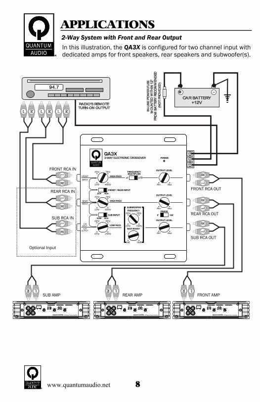
2-Way System with Front and Rear OutputIn this illustration, the QA3X is configured for two channel input withdedicated amps for front speakers, rear speakers and subwoofer(s).
APPLICATIONS
CAR BATTERY+12V
-+
IN-L
INE
POW
ER F
USE
MO
UN
TED
WIT
HIN
12"
FRO
M B
ATTE
RY R
ECO
MM
END
ED(N
OT
PRO
VID
ED)
94.7
RADIO'S REMOTETURN-ON OUTPUT
FRONT RCA IN
REAR RCA IN
SUB RCA IN
Optional Input
SUB AMP REAR AMP FRONT AMP
SUB RCA OUT
REAR RCA OUT
FRONT RCA OUT
8www.quantumaudio.net

2-Way System with Front and Rear Output(Switch Configurations)
APPLICATIONS
FRONT RCA IN
REAR RCA IN
SUB RCA IN
FRONT RCA IN
REAR RCA IN
FRONT RCA IN
For 2 channel input,configure switches as shown
For 4 channel input with front andrear fade, configure switches
as shown
For front and rear fade withdedicated subwoofer input, configure
switches as shown
9 www.quantumaudio.net
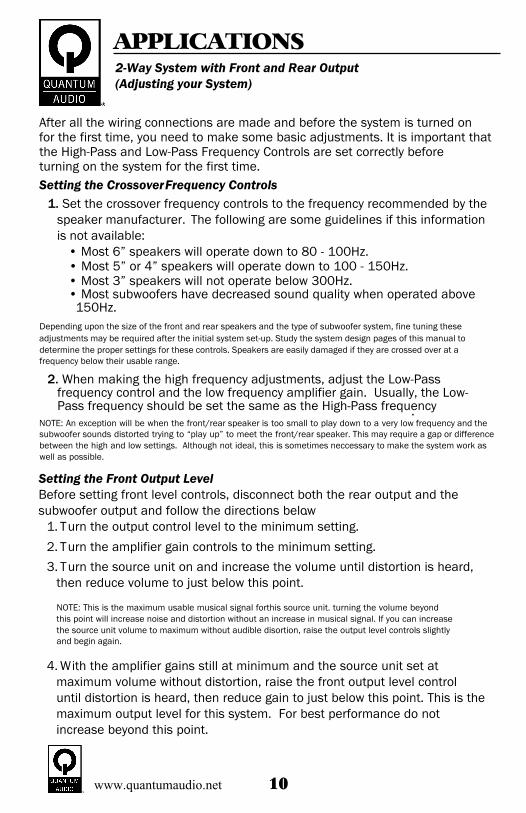
After all the wiring connections are made and before the system is turned onfor the first time, you need to make some basic adjustments. It is important thatthe High-Pass and Low-Pass Frequency Controls are set correctly beforeturning on the system for the first time.Setting the CrossoverFrequency Controls
1. Set the crossover frequency controls to the frequency recommended by thespeaker manufacturer.. The following are some guidelines if this informationis not available: • Most 6” speakers will operate down to 80 - 100Hz. • Most 5” or 4” speakers will operate down to 100 - 150Hz. • Most 3” speakers will not operate below 300Hz. • Most subwoofers have decreased sound quality when operated above
150Hz.Depending upon the size of the front and rear speakers and the type of subwoofer system, fine tuning theseadjustments may be required after the initial system set-up. Study the system design pages of this manual todetermine the proper settings for these controls. Speakers are easily damaged if they are crossed over at a frequency below their usable range.
2. When making the high frequency adjustments, adjust the Low-Passfrequency control and the low frequency amplifier gain. Usually, the Low-Pass frequency should be set the same as the High-Pass frequency.
NOTE: An exception will be when the front/rear speaker is too small to play down to a very low frequency and thesubwoofer sounds distorted trying to “play up” to meet the front/rear speaker. This may require a gap or differencebetween the high and low settings. Although not ideal, this is sometimes neccessary to make the system work aswell as possible.
Setting the Front Output LevelBefore setting front level controls, disconnect both the rear output and thesubwoofer output and follow the directions below.
1. Turn the output control level to the minimum setting.2. Turn the amplifier gain controls to the minimum setting.3. Turn the source unit on and increase the volume until distortion is heard,
then reduce volume to just below this point.
NOTE: This is the maximum usable musical signal forthis source unit. turning the volume beyondthis point will increase noise and distortion without an increase in musical signal. If you can increasethe source unit volume to maximum without audible disortion, raise the output level controls slightlyand begin again.
4. With the amplifier gains still at minimum and the source unit set atmaximum volume without distortion, raise the front output level controluntil distortion is heard, then reduce gain to just below this point. This is themaximum output level for this system. For best performance do notincrease beyond this point.
2-Way System with Front and Rear Output(Adjusting your System)
APPLICATIONS
10www.quantumaudio.net

Setting the Rear Output LevelBefore setting rear level controls, disconnect both the front output and thesubwoofer output and follow the directions below.
1. Turn the output control level to the minimum setting. 2. Turn the amplifier gain controls to the minimum setting.3. Turn the source unit on and increase the volume until distortion is heard,
then reduce volume to just below this point.NOTE: This is the maximum usable musical signal for this source unit. turning the volume beyond this point willincrease noise and distortion without an increase in musical signal. If you can increase the source unit volume tomaximum without audible disortion, raise the output level controls slightly and begin again.
4. With the amplifier gains still at minimum and the source unit set atmaximum volume without distortion, raise the rear output level control untildistortion is heard, then reduce gain to just below this point. This is themaximum output level for this system. For best performance, do not increasebeyond this point.
Setting the Sub Output Level1. Make sure all ouputs are connected and the front and rear output levels are
set correctly. Unplug the Remote Sub Level control cable.2. Be sure the sub output level and amplifier gains are at their minimum
settings.3. With the volume set at a medium level, slowly increase the sub level
control to the point where the subwoofer volume blends with the system.4. If maximum sub output level does not provide enough subwoofer volume,
slightly increase the subwoofer amplifier gain until desired level is reached.5. Fine tune the bass response using the Sub Boost Controls.6. Plug the Remote Sub Level Control cable back into the QA3X crossover.
Setting the Sub Boost Level1. Initially set the sub boost level to the minimum setting (i.e. 0dB).2. Listen to a variety of music styles (e.g. Rock, Rap, etc.) and slowly
increase the Sub Boost control until a noticeable increase in low bassresponse is perceived.
3. Slowly adjust the Sub Boost Frequency control (up or down) to realize thebest bass response.
CAUTION: This feature can make a subwoofer put out more energy at very low frequencies. Be cautious with this control because with too much boost at low frequencies the power handling of the subwoofer will be decreased.This is a subjective setting and will depend on your personal listening preferences. If you hear a “pop” (due to over-excursion), lower the Sub Boost to prevent speaker damage. If the system sounds muddy and distorted (due to amplifier clipping), lower Sub Boost to avoid shutdown from overheating.
2-Way System with Front and Rear Output(Adjusting your System - cont.)
APPLICATIONS
11 www.quantumaudio.net

3-Way SystemIn this illustration, the QA3X is configured for single channel inputwith dedicated amplifiers for tweeters, midranges, and subwoofer(s).
APPLICATIONS
D
CAR BATTERY+12V
-+
IN-L
INE
POW
ER F
USE
MO
UN
TED
WIT
HIN
12"
FRO
M B
ATTE
RY R
ECO
MM
END
E(N
OT
PRO
VID
ED)
94.7
RADIO'S REMOTETURN-ON OUTPUT
FRONT RCA IN
SUB AMP MID AMP HIGH AMP
SUB RCA OUT
MID RCA OUT
HIGH RCA OUT
12www.quantumaudio.net

After all the wiring connections are made and before the system is turned onfor the first time, you need to make some basic adjustments. It is important thatthe High-Pass and Low-Pass Frequency Controls are set correctly beforeturning on the system for the first time.Setting the Crossover Frequency Controls
1. Set the crossover frequency controls to the frequency recommended by thespeaker manufacturer.. The following are some guidelines if this informationis not available:
• Most tweeters will not operate below 5000Hz. • Most 6” midranges will operate down to 80-100Hz. • Most 5” or 4” midranges will operate down to 125-200Hz. • Most subwoofers have decreased sound quality when operated above
150Hz.Depending upon the size/type of the midranges and tweeters and the type of subwoofer system, fine tuning theseadjustments may be required after the initial system set-up. Study the system design pages of this manual to determine the proper settings for these controls. Midranges and tweeters are easily damaged if they cross at afrequency below their useable range.
2. The Low-Pass frequency should be set the same as the High-Passfrequency.
NOTE: An exception will be when the midrange is too small to play down to a very low frequency and the subwoofersounds distorted trying to “play up” to meet the midrange. This may require a gap or difference between the highand low settings. Although not ideal, this is sometimes necessary to make the system work as well as possible.
Setting the Front and Rear Output LevelsBefore setting front and rear level controls, disconnect the subwoofer outputand follow the directions below.
1. Be sure the front and rear High-Pass crossovers are set properly.NOTE: When the QA3X is used in a 3-way system, the front outputs must be connected to the tweeter, amplifier, andthe rear outputs must be connected to the midrange amplifier.
2. Turn the front and rear output level controls to their minimum setting.3. Turn the amplifier gain controls to their minimum setting.4. Turn the source unit on and increase the volume until distortion is heard,
then reduce volume to just below this point.NOTE: This is the maximum usable musical signal for this source unit. Turning the volume beyond this point willincrease noise and distortion without an increase in musical signal. If you can increase the source unit volume tomaximum without audible disortion, raise the output level controls slightly and begin again.
5. With the amplifier gains still at minimum and the source unit set at maximumvolume without distortion, raise the front and rear output level controls untildistortion is heard, then reduce the gain to just below this point. This is the maximum output level for this system. For best performance, do not increasebeyond this point.
3-Way System(Adjusting your System)
APPLICATIONS
13 www.quantumaudio.net

Setting the Sub Output Level1. Make sure all outputs are connected and both the front and rear output
levels are set correctly. Unplug the Remote Sub Level control cable.2. Be sure the sub output level and amplifier gains are at their minimum
settings.3. With the volume set at a medium level, slowly increase the sub level
control to the point where the subwoofer volume blends with the system. 4. If maximum sub output level does not provide enough subwoofer volume,
slightly increase the subwoofer amplifier gain until desired level is reached.5. Fine tune the bass response using the Sub Boost Controls.6. Plug the Remote Sub Level Control cable back into the QA3X
crossover.Setting the Sub Boost Level
Troubleshooting your System
1. Initially set the sub boost level to its minimum setting (i.e. 0dB).2. Listen to a variety of music styles (e.g. Rock, Rap, etc.) and slowly
increase the Sub Boost control until a noticeable increase in low bassresponse is perceived.
3. Slowly adjust the Sub Boost Frequency control (up or down) to realize thebest bass response.
CAUTION: This feature can make a subwoofer put out more energy at very low frequencies. Be cautious with this control because with too much boost at low frequencies, the power handling of the subwoofer will be decreased.This is a subjective setting and will depend on your personal listening preferences. If you hear a “pop” (due to speaker over-excursion), lower the Sub Boost to prevent speaker damage. If the system sounds muddy anddistorted (due to amplifier clipping), lower Sub Boost to avoid shutdown from overheating.
Problem:Music is not loud enough with source unit turned up.Solution:Output Level Controls are set incorrectly.Problem:Music gets loud and distorted with source unit turned up only part way.Solution:Output Level Controls are set incorrectly.Gain Controls on amplifiers are set incorrectly.
3-Way System(Adjusting your System - cont. / Troubleshooting)
APPLICATIONS
Problem:Green power indicator LED not on, there is no sound.Solution:Check the CONSTANT and REMOTE (Switched) wiring connections.Check the GROUND wiring for good connections.
14www.quantumaudio.net

Problem:Midrange speakers “pop” with loud passages.Solution:High-Pass Frequency Control is set too low.Gain Controls on amplifiers are set incorrectly. Reduce the gain setting on highfrequency amplifier.
Problem:One channel does not operate.Solution:Swap left and right connections at the source unit. If the problem trades sidesin the vehicle, then the source unit is the defective. If the problem stays on thesame side, proceed on.Swap left and right connections at the input to the crossover. If the problemtrades sides in the vehicle, then the wiring is defective between the source unitand the crossover. If the problem stays on the same side, proceed on.Swap the left and right High-Pass RCAs at the output of the crossover. If theproblem trades sides in the vehicle, then the crossover is defective. If theproblem stays on the same side, proceed on.Swap the left and right High-Pass RCAs at the amplifier input. If the problemtrades sides in the vehicle, then the RCA cable is defective. If the problemstays on the same side, proceed on.Swap the left and right speaker connections at the output of the High-Passamplifier. If the problem trades sides in the vehicle, then the amplifier isdefective. If the problem stays on the same side, then the speaker or speakerwiring is defective.
QA3X SPECIFICATIONSPower Source:Input Current:Distortion:Frequency Response:S/N Ratio:Seperation:Crossover Slope:Input Impedance:Output Impedance:Output Gain:Output Voltage Level:Dimensions:
14.4 Volts DC0.5 Amp Max
0.01% THD10Hz - 30kHz - 3dB
>100dB60dB
18dB per octave20K Ohms100 Ohms1:2 (+6dB)5 volts max
152mm x 180mm x 43mm
Troubleshooting Your System / Product Specifications
Troubleshooting
15 www.quantumaudio.net

Tel : 956-428-4263 Fax : 956-421-4513www.quantumaudio.net