Embed Size (px)
Citation preview
11THE PROPOSAL
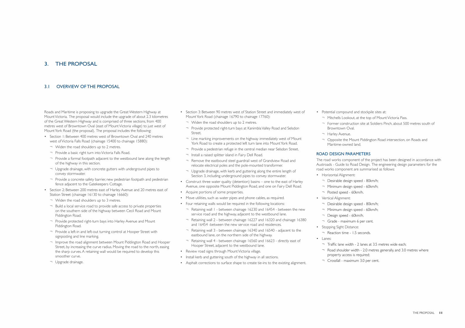
Roads and Maritime is proposing to upgrade the Great Western Highway at Mount Victoria. The proposal would include the upgrade of about 2.3 kilometres of the Great Western Highway and is comprised of three sections, from 400 metres west of Browntown Oval (east of Mount Victoria village) to just west of Mount York Road (the proposal). The proposal includes the following:
• Section 1: Between 400 metres west of Browntown Oval and 240 metres west of Victoria Falls Road (chainage 15400 to chainage 15880):
¬ Widen the road shoulders up to 2 metres.
¬ Provide a basic right turn into Victoria Falls Road.
¬ Provide a formal footpath adjacent to the westbound lane along the length of the highway in this section.
¬ Upgrade drainage, with concrete gutters with underground pipes to convey stormwater.
¬ Provide a concrete safety barrier, new pedestrian footpath and pedestrian fence adjacent to the Gatekeepers Cottage.
• Section 2: Between 200 metres east of Harley Avenue and 20 metres east of Station Street (chainage 16130 to chainage 16660):
¬ Widen the road shoulders up to 3 metres.
¬ Build a local service road to provide safe access to private properties on the southern side of the highway between Cecil Road and Mount Piddington Road.
¬ Provide protected right-turn bays into Harley Avenue and Mount Piddington Road.
¬ Provide a left-in and left-out turning control at Hooper Street with signposting and line marking.
¬ Improve the road alignment between Mount Piddington Road and Hooper Street, by increasing the curve radius. Moving the road to the north, easing the sharp curves. A retaining wall would be required to develop this smoother curve.
¬ Upgrade drainage.
3. THE PROPOSAL
• Section 3: Between 90 metres west of Station Street and immediately west of Mount York Road (chainage 16790 to chainage 17760):
¬ Widen the road shoulders up to 2 metres.
¬ Provide protected right-turn bays at Kanimbla Valley Road and Selsdon Street.
¬ Line marking improvements on the highway immediately west of Mount York Road to create a protected left turn lane into Mount York Road.
¬ Provide a pedestrian refuge in the central median near Selsdon Street.
¬ Install a raised splitter island in Fairy Dell Road.
¬ Remove the eastbound steel guardrail west of Grandview Road and relocate electrical poles and the pole-mounted transformer.
¬ Upgrade drainage, with kerb and guttering along the entire length of Section 3, including underground pipes to convey stormwater.
• Construct three water quality (detention) basins – one to the east of Harley Avenue, one opposite Mount Piddington Road, and one on Fairy Dell Road.
• Acquire portions of some properties.
• Move utilities, such as water pipes and phone cables, as required.
• Four retaining walls would be required in the following locations:
¬ Retaining wall 1 - between chainage 16230 and 16454 - between the new service road and the highway, adjacent to the westbound lane.
¬ Retaining wall 2 - between chainage 16227 and 16320 and chainage 16380 and 16454 -between the new service road and residences.
¬ Retaining wall 3 - between chainage 16340 and 16540 - adjacent to the eastbound lane, on the northern side of the highway.
¬ Retaining wall 4 - between chainage 16560 and 16623 - directly east of Hooper Street, adjacent to the westbound lane.
• Review road signs through Mount Victoria village.
• Install kerb and guttering south of the highway in all sections.
• Asphalt corrections to surface shape to create tie-ins to the existing alignment.
3.1 OVERVIEW OF THE PROPOSAL
• Potential compound and stockpile sites at:
¬ Mitchells Lookout, at the top of Mount Victoria Pass.
¬ Former construction site at Soldiers Pinch, about 500 metres south of Browntown Oval.
¬ Harley Avenue.
¬ Opposite the Mount Piddington Road intersection, on Roads and Maritime-owned land.
ROAD DESIGN PARAMETERSThe road works component of the project has been designed in accordance with Austroads - Guide to Road Design. The engineering design parameters for the road works component are summarised as follows:
• Horizontal Alignment:
¬ Desirable design speed - 80km/h;
¬ Minimum design speed - 60km/h;
¬ Posted speed - 60km/h.
• Vertical Alignment:
¬ Desirable design speed - 80km/h;
¬ Minimum design speed - 60km/h;
¬ Design speed - 60km/h.
¬ Grade - maximum 6 per cent.
• Stopping Sight Distance:
¬ Reaction time - 1.5 seconds.
• Lanes:
¬ Traffi c lane width - 2 lanes at 3.5 metres wide each;
¬ Road shoulder width - 2.0 metres generally, and 3.0 metres where property access is required;
¬ Crossfall - maximum 3.0 per cent.
12 K2L | MOUNT VICTORIA VILLAGE SAFETY UPGRADE URBAN DESIGN AND LC&VIA REPORT
EARTHWORKSWidening work is primarily being carried out south of the existing pavement, requiring cut batters and retaining walls to minimise property and heritage impacts. Fill is required opposite Mount Piddington Road and a retaining wall is used to avoid a long spill embankment which would chase the existing slope and impact on existing trees. Further consideration will be given to the proposed walls, cut and spill batters during detailed design to determine their suitability within the village environment.
DRAINAGERoad drainage generally consists of three key elements; cross drainage, longitudinal drainage and water quality treatment.
There is currently very little formal longitudinal drainage within the village, with swales and some kerb and gutter provided.
The existing kerb and gutter is proposed to be retained wherever possible and new kerb and gutter proposed to be implemented.
Water quality treatment areas are proposed in the form of three bio-fi ltration basins on the north side of the highway, to the east of Hooper Street.
UTILITIESThere are a number of existing utilities within the road corridor that will require consideration / relocation as part of the proposed work. These include:
• Electricity.
• Telecommunications.
• Water.
• Sewer.
• Gas.
LANDSCAPE WORKS
In addition to the key engineering works previously outlined, the following landscape works are envisaged to be undertaken as part of the detail design phase of the project:
• Clearing of existing roadside trees and other vegetation in some locations to provide adequate space for the proposed road safety works.
• Landscape revegetation works, including tree, shrub and groundcover planting to cut and fi ll batters and roadside areas, particularly to the bushland areas in Section 1.
• Exotic street tree and intersection tree planting in the village.
STRUCTURES AND ROADSIDE ELEMENTS
The following structures and roadside elements have been included in the proposal and would require further investigation during the detail design phase:
• Construction of four new retaining walls in the central section of the upgrade.
• Minor cut and fi ll embankments to reconcile level changes.
• New footpaths and shared paths.
• The installation of roadside elements such as wire rope barriers, fencing, signage, and street lighting through the village.
13LANDSCAPE AND URBAN DESIGN STRATEGY
4. URBAN DESIGN STRATEGY
A central component of the design process is the identifi cation of urban design objectives. These objectives cover the full range of components associated with the road design including alignment, adjoining property access, road corridor character and road infrastructure elements. These elements include cut and fi ll batters, walling, drainage structures, fences and barriers, planting and landscaped surfaces.
The objectives refl ect an essential goal to achieve a project outcome which is sensitively integrated, taking into account not only the corridor itself but also its relationship with surrounding areas. These would be implemented in accordance with the Roads and Maritime policy Beyond the Pavement (2009) performance themes of safety, cost effectiveness and sustainability.
An integrated design approach has been adopted for the Mount Victoria safety works project in order to ensure that the best possible outcomes are achieved. As part of the integrated design approach, a landscape and urban design strategy has been developed to provide urban design input to the overall concept design for the works.
The purpose of the strategy is to articulate how urban design can contribute to the successful achievement of the overall project objectives. The development of the strategy has directly infl uenced key engineering aspects of the concept road design to date, including road alignment, typical cross sections and retaining walls. The intention is that this urban design strategy would further infl uence the development of the highway works when it proceeds to concept design, detailed design and construction.
The plans and sections at the end of the chapter indicatively illustrate the urban design proposal developed as part of the road design.
4.1 OVERVIEW
Objective 2: Provide a good urban design outcome, taking into account the existing amenity, visual character and cultural landscapes of Mount Victoria.
Design principles:
• Not precluding Council’s potential future plans for the area, which are yet to be determined.
• Enhance opportunities to defi ne the entry and approach to Mount Victoria on the Great Western highway from both the east and west.
• Maximise opportunities to enhance and improve pedestrian and cycle connections between the village centre and adjoining areas including Browntown Oval to the east and Mount York Reserve to the west.
• Retain, and where possible improve, views to important landmarks and the local heritage buildings.
Objective 3: Maintain the integrity of cultural and historic buildings, structures, elements and spaces of Mount Victoria.
Design principles:
• Maintain the physical and visual integrity of State-signifi cant items including heritage buildings, public spaces and their curtilage, particularly within the central Mount Victoria urban conservation area.
• Preserve the integrity of heritage items and areas of cultural importance to the local community.
• Minimise impacts on Aboriginal heritage sites and their associated heritage values.
Objective 4: Improve safety and connectivity for motorists, pedestrians and cyclists.
Design principles:
• Provide safe, direct and obvious connections between the village centre and adjoining areas, including public open spaces, reserves and sport fi elds.
• Provide reasonable cycle and pedestrian connections.
4.2 URBAN DESIGN OBJECTIVES AND PRINCIPLES
The following urban design objectives have been devised to guide the development of the future concept design outcome for the project. These objectives are;
1. Develop an integrated concept design that fi ts sensitively with the existing qualities and characteristics of Mount Victoria and its setting at the western end of the Blue Mountains World Heritage Area.
2. Provide a good urban design outcome, taking into account the existing amenity, visual character and cultural landscapes of Mount Victoria.
3. Maintain the integrity of cultural and historic buildings, structures, elements and spaces of Mount Victoria.
4. Improve safety and connectivity for motorists, pedestrians and cyclists.
Objective 1: Develop an integrated concept design that fi ts sensitively with the existing qualities and characteristics of Mount Victoria and its setting at the western end of the Blue Mountains World Heritage Area.
Design principles:
• Maintain the landmark qualities of Mount Victoria as the western most village on the Great Western Highway in the Blue Mountains World Heritage Area.
• Minimise the physical footprint and scale of new infrastructure in order to retain the existing qualities and characteristics of Mount Victoria.
• Ensure that the new works are well integrated with the adjoining built areas, open space, historic and natural settings.
• Minimise negative physical impacts on parklands, open spaces, heritage items and private property.
• Minimise the extent and scale of road-related elements including retaining walls and barriers.
• Consolidate any residual land parcels into adjoining land uses as appropriate.
14 K2L | MOUNT VICTORIA VILLAGE SAFETY UPGRADE URBAN DESIGN AND LC&VIA REPORT
4.3 STRUCTURES
RETAINING WALLSThe highway safety upgrade requires a number of retaining walls to reconcile the proposed alignment levels with the existing ground. Retaining walls may be required:
• Below the proposed highway (ie where the highway is on fi ll).
• Above the proposed highway (ie where the highway is in cut).
Retaining walls may also be required where modifi cations are proposed to property access and local roads.
Tables 4.1 and 4.2 provide a summary of urban design recommendations for retaining walls.
CUTTINGS AND EMBANKMENTSThe highway saefty upgrade has been designed to be kept as close as possible to the existing highway levels. Any cuttings or fi ll embankments would be minor and would either be planted with native shrubs and groundcovers (bushland areas) or turfed (the village).
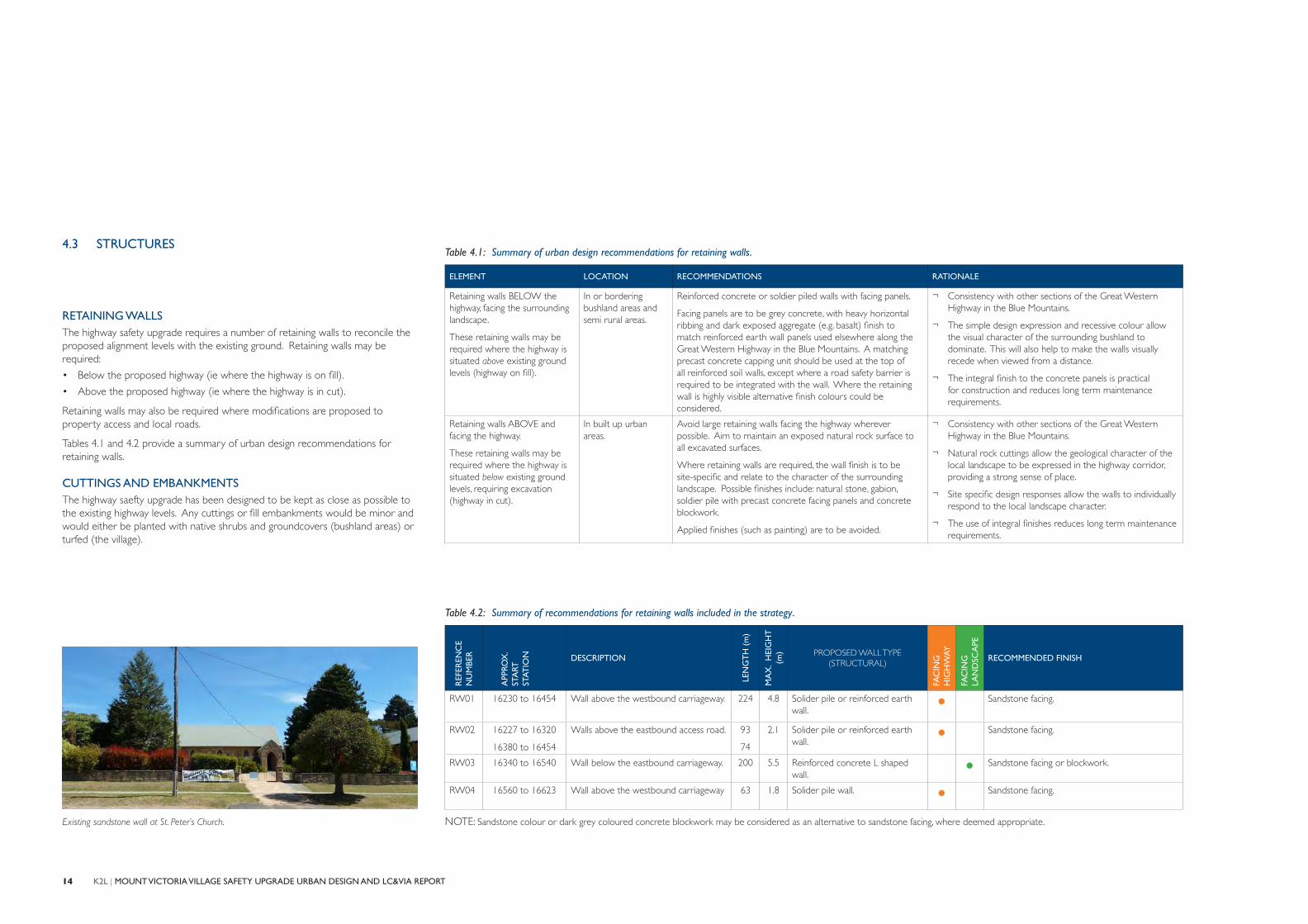
Existing sandstone wall at St. Peter’s Church.
Table 4.1: Summary of urban design recommendations for retaining walls.
ELEMENT LOCATION RECOMMENDATIONS RATIONALE
Retaining walls BELOW the highway, facing the surrounding landscape.
These retaining walls may be required where the highway is situated above existing ground levels (highway on fi ll).
In or bordering bushland areas and semi rural areas.
Reinforced concrete or soldier piled walls with facing panels.
Facing panels are to be grey concrete, with heavy horizontal ribbing and dark exposed aggregate (e.g. basalt) fi nish to match reinforced earth wall panels used elsewhere along the Great Western Highway in the Blue Mountains. A matching precast concrete capping unit should be used at the top of all reinforced soil walls, except where a road safety barrier is required to be integrated with the wall. Where the retaining wall is highly visible alternative fi nish colours could be considered.
¬ Consistency with other sections of the Great Western Highway in the Blue Mountains.
¬ The simple design expression and recessive colour allow the visual character of the surrounding bushland to dominate. This will also help to make the walls visually recede when viewed from a distance.
¬ The integral fi nish to the concrete panels is practical for construction and reduces long term maintenance requirements.
Retaining walls ABOVE and facing the highway.
These retaining walls may be required where the highway is situated below existing ground levels, requiring excavation (highway in cut).
In built up urban areas.
Avoid large retaining walls facing the highway wherever possible. Aim to maintain an exposed natural rock surface to all excavated surfaces.
Where retaining walls are required, the wall fi nish is to be site-specifi c and relate to the character of the surrounding landscape. Possible fi nishes include: natural stone, gabion, soldier pile with precast concrete facing panels and concrete blockwork.
Applied fi nishes (such as painting) are to be avoided.
¬ Consistency with other sections of the Great Western Highway in the Blue Mountains.
¬ Natural rock cuttings allow the geological character of the local landscape to be expressed in the highway corridor, providing a strong sense of place.
¬ Site specifi c design responses allow the walls to individually respond to the local landscape character.
¬ The use of integral fi nishes reduces long term maintenance requirements.
NOTE: Sandstone colour or dark grey coloured concrete blockwork may be considered as an alternative to sandstone facing, where deemed appropriate.
Table 4.2: Summary of recommendations for retaining walls included in the strategy.
REF
EREN
CE
NU
MBE
R
APP
ROX
.ST
ART
ST
ATIO
N DESCRIPTION
LEN
GT
H (
m)
MA
X.
HEI
GH
T
(m) PROPOSED WALL TYPE
(STRUCTURAL)
FAC
ING
H
IGH
WAY
FAC
ING
LA
ND
SCA
PE
RECOMMENDED FINISH
RW01 16230 to 16454 Wall above the westbound carriageway. 224 4.8 Solider pile or reinforced earth wall.
• Sandstone facing.
RW02 16227 to 16320
16380 to 16454
Walls above the eastbound access road. 93
74
2.1 Solider pile or reinforced earth wall.
• Sandstone facing.
RW03 16340 to 16540 Wall below the eastbound carriageway. 200 5.5 Reinforced concrete L shaped wall.
• Sandstone facing or blockwork.
RW04 16560 to 16623 Wall above the westbound carriageway 63 1.8 Solider pile wall. • Sandstone facing.
15LANDSCAPE AND URBAN DESIGN STRATEGY
Table 4.3: Summary of recommendations for roadside elements within the road corridor.
ELEMENT LOCATION RECOMMENDATION RATIONALE
BARRIERS, FENCES AND BALUSTRADES
At the top of fi ll embankments and other roadside situations
Either W Beam guard rail or wire rope barrier, as appropriate for the situation. Either barrier type should preferably be used in conjunction with planting behind.
Where space is limited or where maximum visual transparency is required, the modifi ed concrete barrier (type F) with twin rail bridge barrier should be used.
¬ Facilitate views from the highway to the surrounding landscape, to provide a sense of connection to the local area.
Property fences Where property fences are required to be replaced or relocated, they should be similar in style to existing. New fencing should generally be a picket style fence for residential properties fronting the highway from Hooper Street through to Mount York Road. Post and rail could be used elsewhere. The use of solid fences are to be avoided.
¬ Maintain and reinforce the existing village character by retaining a mix of individual fence styles.
¬ Minimise the height of fences wherever possible.
¬ Reduce the visual dominance of fences.
Balustrades Vertical black steel rods, 1.4 metre high as per standard use throughout the Blue Mountains.
¬ Reduce the visual dominance of balustrades.
¬ Provides transparency to allow for adjoining vegetation to add to the character of pathways and roadways.
STREET LIGHTING Required for the length of the new works.
Lighting to be minimised to meet requirements set out in AS1158.
Ensure uniformity in size, height and spacing of lights.
Use galvanised steel light posts, black or dark grey fi nish.
¬ Reduce visual dominance of the works, to retain the village character.
¬ Provide for safe pedestrian and cycle circulation and access.
¬ Potential for lighting in the village centre and its approaches to be unique and distinctive and in keeping with the village character.
SIGNAGE All areas. There needs to be a balance of regulatory signage and local information signage as part of the works.
¬ The need for signage within the highway corridor should be appropriate and suitable within the context of Mount Victoria village.
DRAINAGE STRUCTURES
All streetscape areas. Drainage structures should be an integral element of the streetscape within the highway corridor. The use of rain gardens and tree pits for treating water run-off should be maximised where possible.
¬ To treat run-off at or near the source and avoid the need for large detention basins elsewhere.
¬ Provide water for plant growth.
¬ Provide community interest and awareness of water harvesting.
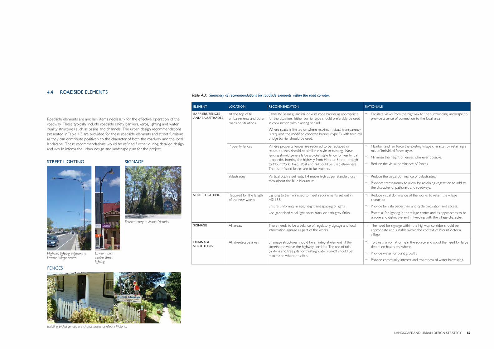
Eastern entry to Mount Victoria.
Highway lighting adjacent to Lawson village centre.
Lawson town centre street lighting
STREET LIGHTING SIGNAGE
Existing picket fences are characteristic of Mount Victoria.
FENCES
Roadside elements are ancillary items necessary for the effective operation of the roadway. These typically include roadside safety barriers, kerbs, lighting and water quality structures such as basins and channels. The urban design recommendations presented in Table 4.3 are provided for these roadside elements and street furniture as they can contribute positively to the character of both the roadway and the local landscape. These recommendations would be refi ned further during detailed design and would inform the urban design and landscape plan for the project.
4.4 ROADSIDE ELEMENTS
16 K2L | MOUNT VICTORIA VILLAGE SAFETY UPGRADE URBAN DESIGN AND LC&VIA REPORT
4.5 PLANTING
PLANTING DESIGN
The general approach to the planting design for this project is to integrate the new works into the existing landscape setting and to further defi ne and reinforce the unique landscape character zones through the village of Mount Victoria. This approach aims to enhance the sense of arrival to Mount Victoria both from the east and west while also strengthening the landscape character of the villages heritage core. In order to do this the planting must strike a balance between screening the works from sensitive visual receptors and maintaining and enhancing key views and vistas to the surrounding landscape.
PLANTING DESIGN PRINCIPLES
The planting concept has been guided by the following design principles:
• Revegetation of all areas affected by the new works.
• Revegetation of residual land affected by the works that would not be viable for amalgamation.
• Provision of ‘gateway’ planting at key intersections and important cultural areas to provide visual landmarks and enhance local identity.
• Provision of street tree planting in verges wherever possible to help minimise the visual scale of the highway.
• Provision of planting on fi ll embankments and shallow cut batters to stabilise the earthworks, minimise their visual impact and integrate them with the character of the surrounding landscape.
• Provision of planting to screen the works from sensitive adjacent land uses where applicable.
• Use of provenance plant material (plants grown from locally collected seeds) wherever possible for all native plantings, in particular native revegetation.
At the detailed planting design stage, which would include further refi nement of the plant species selection, particular consideration should be made for ongoing maintenance requirements.
Table 4.4: Indicative exotic plant species list
BOTANICAL NAME COMMON NAMEMATURE HEIGHT
MATURE SPREAD
HIGHWAY PLANTING - MEDIUM TREE SPECIES
* Acer x freemanii ‘Jeffers Red’ Autumn Blaze Maple 13m 10m
* Arbutus unedo Strawberry Tree 9m 5m
* Platanus digitata Plane Tree 15m 10m
Populus Yunnanensis Yunnan Poplar 17m 8m
Pyrus calleryana Flowering Pear 11m 6m
Ulmus glabra ‘Lutescens’ Golden Elm 10m 12m
LOCAL ROAD AND FEATURE - SMALL TO MEDIUM TREE SPECIES
Liriodendron tulipifera ‘Fastigitata’ Narrow Tulip Tree 13m 5m
Malus ioensis ‘Plena’ Flowering Crabapple 6m 4.5m
Pistachia chinensis Pistachio 8m 6m
Prunus serrulata Flowering Cherry 5m 4m
Zelkova serrata Japanese Zelkova 10m 4m
GATEWAY AND OPEN SPACE - LARGE TREE SPECIES
Cedrus atlantica ‘Glauca’ Atlas Cedar 20m 10m
Cryptomeria japonica Japanese Cedar 25m 6m
# Fagus sylvatica ‘Purpurea’ Purple Beech 20m 12m
Ginkgo biloba Maidenhair Tree 12m 5m
Liquidamber styracifl ua Liquidamber 20m 10m
# Quercus palustris Pin Oak 20m 8m
NOTE: * = primary street tree species. # = primary gateway species.
Principles include:
¬ Selection of plant species that are robust, non-invasive and not fi re-promoting.
¬ Use of local provenance plant material for native revegetation plantings, particularly in riparian areas.
¬ Use of species climatically suited to the local area for cultural plantings.
¬ Exclusion of all species on weed lists applicable to the local area.
¬ Placement and species selection for planting within the road corridor (e.g verges) to be in accordance with clear zone and sight stopping distance requirements.
INDICATIVE PLANTING PALETTE
An indicative planting palette has been developed for the planting concept, which provides the framework for detailed species selection and planting design during the detailed design phase. The fi nal selection of plant species would be undertaken in consultation with Council, the local community and key stakeholders.
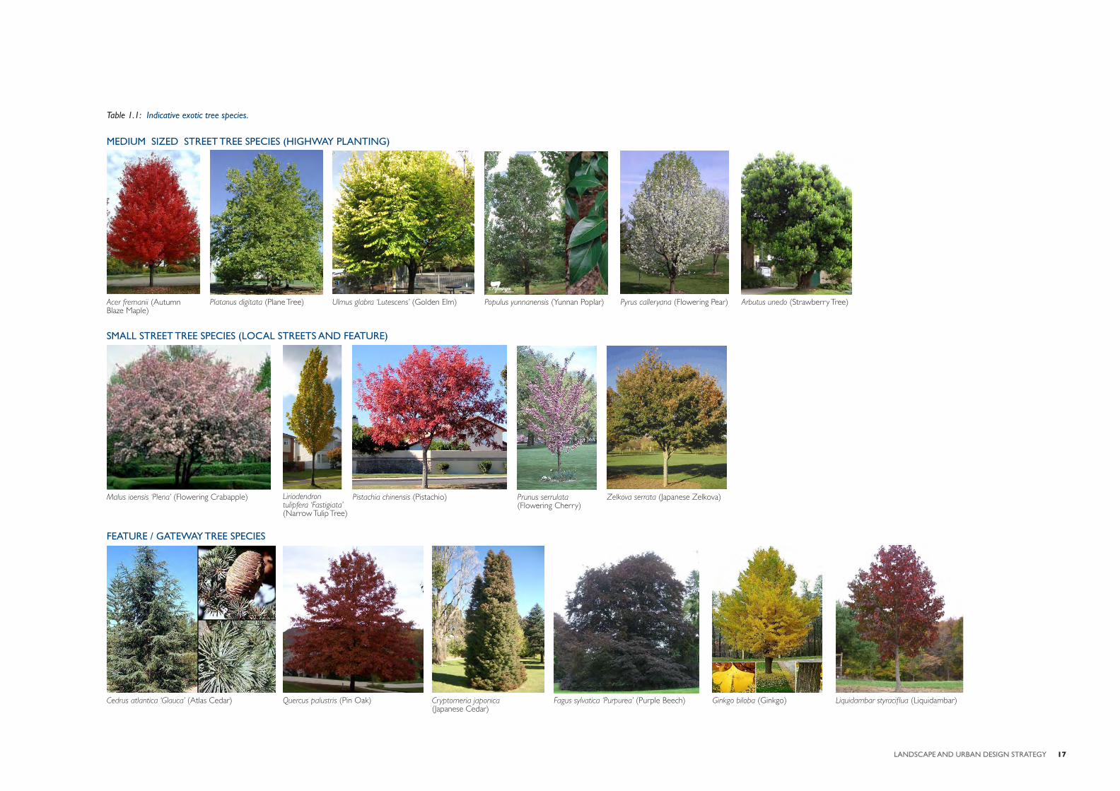
The indicative planting palette has been divided into an exotic species list and native plant list as indicated in table 4.4 and 4.5. A selection of images for the key tree species proposed is also presented on the following page.
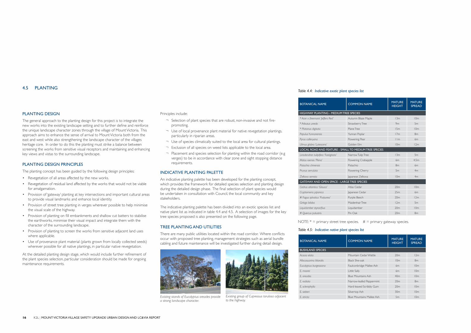
TREE PLANTING AND UTILITIES
There are many public utilities located within the road corridor. Where confl icts occur with proposed tree planting, management strategies such as aerial bundle cabling and future maintenance will be investigated further during detail design.
Table 4.5: Indicative native plant species list
BOTANICAL NAME COMMON NAMEMATURE HEIGHT
MATURE SPREAD
BUSHLAND SPECIES
Acacia elata Mountain Cedar Wattle 20m 12m
Allocasuarina littoralis Black She-oak 10m 8m
Eucalyptus burgessiana Faulconbridge Mallee Ash 6m 10m
E. moorei Little Sally 6m 10m
E. oreades Blue Mountains Ash 40m 10m
E. radiata Narrow-leafed Peppermint 20m 8m
E. sclerophylla Hard-leaved Scribbly Gum 20m 10m
E. sieberi Silvertop Ash 30m 10m
E. stricta Blue Mountains Mallee Ash 5m 10mExisting stands of Eucalyptus oreades provide a strong landscape character.
Existing group of Cupressus torulosa adjacent to the highway.
17LANDSCAPE AND URBAN DESIGN STRATEGY
Acer fremanii (Autumn Blaze Maple)
Arbutus unedo (Strawberry Tree)Platanus digitata (Plane Tree) Ulmus glabra ‘Lutescens’ (Golden Elm)
Ginkgo biloba (Ginkgo) Liquidambar styracifl ua (Liquidambar)Cedrus atlantica ‘Glauca’ (Atlas Cedar) Quercus palustris (Pin Oak) Cryptomeria japonica (Japanese Cedar)
Fagus sylvatica ‘Purpurea’ (Purple Beech)
Malus ioensis ‘Plena’ (Flowering Crabapple) Liriodendron tulipfera ‘Fastigiata’ (Narrow Tulip Tree)
Pistachia chinensis (Pistachio)
Populus yunnanensis (Yunnan Poplar) Pyrus calleryana (Flowering Pear)
Prunus serrulata (Flowering Cherry)
Zelkova serrata (Japanese Zelkova)
MEDIUM SIZED STREET TREE SPECIES (HIGHWAY PLANTING)
FEATURE / GATEWAY TREE SPECIES
Table 1.1: Indicative exotic tree species.
SMALL STREET TREE SPECIES (LOCAL STREETS AND FEATURE)
18 K2L | MOUNT VICTORIA VILLAGE SAFETY UPGRADE URBAN DESIGN AND LC&VIA REPORT
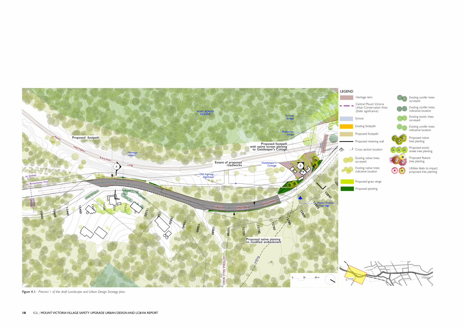
Figure 4.1: Precinct 1 of the draft Landscape and Urban Design Strategy plan.
MEDIUM PERFORMANCE
BARRIER
MAINTENANCE
ACCESS
GATEKEEPERS COTTAGE
SAFETY BARRIER
0 .6
MEDIUM PERFORMANCE
LEVEL TRAFFIC
BARRIER
1 . 3 HIGH PEDESTRIAN
FENCE
0 . 4
3 . 5LANE
1 . 0
1 . 2PATH
EXISTING
RETAININGWALL
15400
15420
15440
15460
15580
15600
15620
15640
15660
15680
15700
15720
15740
15760
15780
15800
15820
15840
158
15400
15420
15440
15460
15580
15600
15620
15640
15660
15680
15700
15720
15740
15760
15780
15800
15820
15840
158
VIC
TOR
IA FA
LLS ROA
D
Gatekeeper'sCottage
FAIRY BOWERRESERVE
Pedestrianbridge
MAIN
WESTERN
RAILWAY
LINE
to Browntown Oval
wal
king
track
to Sydney
80km
/h60
km/h
GREAT WESTERNHIGHWAY
Old highwayalignment
Mount VictoriaVillage sign
Heritageculvert
Railwaybridge
A BExtent of proposed
roadworks
Proposed footpath
Proposed footpathwith native screen planting
to Gatekeeper's Cottage
Proposed native planting to modified embankment
SydneyLithgow
LEGEND
Heritage item
Central Mount VictoriaUrban Conservation Area(State significance)
School
Existing footpath
Proposed footpath
Proposed retaining wall
A Cross section location
Existing native treessurveyed
Existing native treesindicative location
Proposed grass verge
Proposed planting
Existing conifer treessurveyed
Existing conifer treesindicative location
Existing exotic treessurveyed
Existing conifer treesindicative location
Proposed native tree planting
Proposed exoticstreet tree planting
Proposed feature tree planting
Utilities likely to impactproposed tree planting
0 20 40 m
19LANDSCAPE AND URBAN DESIGN STRATEGY
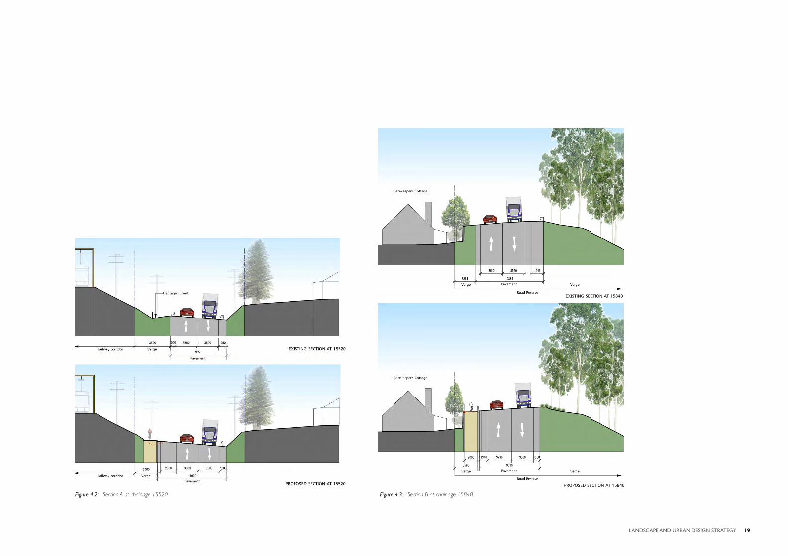
Figure 4.2: Section A at chainage 15520. Figure 4.3: Section B at chainage 15840.
ss
PROPOSED SECTION AT 15840
EXISTING SECTION AT 15840
21LANDSCAPE AND URBAN DESIGN STRATEGY
sss
JAN-082B E A U T I F U L
B R I T I S H COLUMBIA
Verge
5850
2000 4160 1000
Pavement
4570
11730
EXISTING SECTION AT 16500
BAN DESIGN AND LANDSCAPE
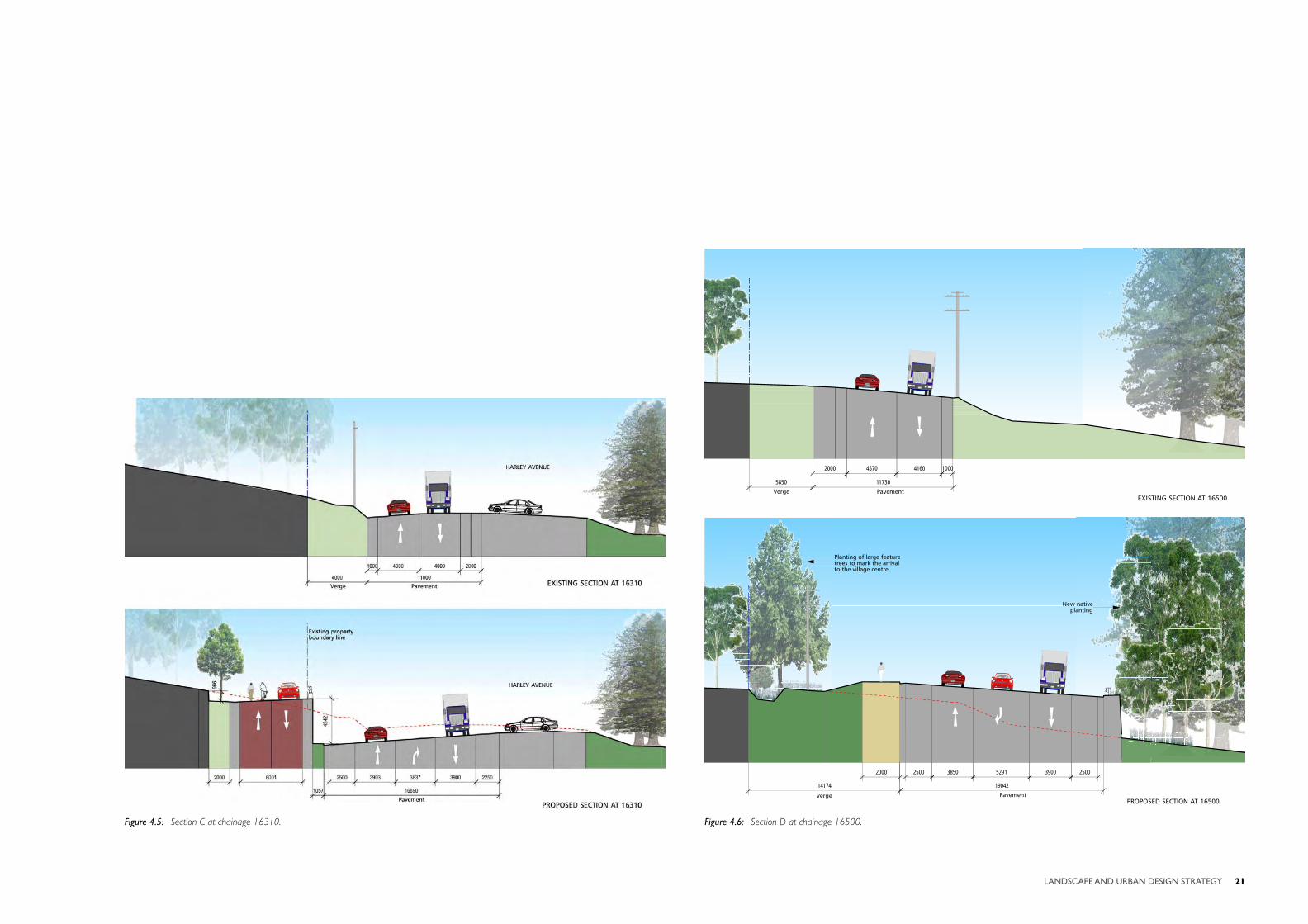
Figure 4.5: Section C at chainage 16310. Figure 4.6: Section D at chainage 16500.
sss
JAN-082B E A U T I F U L
B R I T I S H COLUMBIA
PROPOSED SECTION AT 16500Verge
14174
2000 3850 5291 3900
19042
Pavement
New nativeplanting
Planting of large feature trees to mark the arrival to the village centre
25002500