Embed Size (px)
Citation preview
3 Slabs
In-depth study and additions to Stahlbeton II
06.11.2019 ETH Zurich | Chair of Concrete Structures and Bridge Design | Advanced Structural Concrete 1
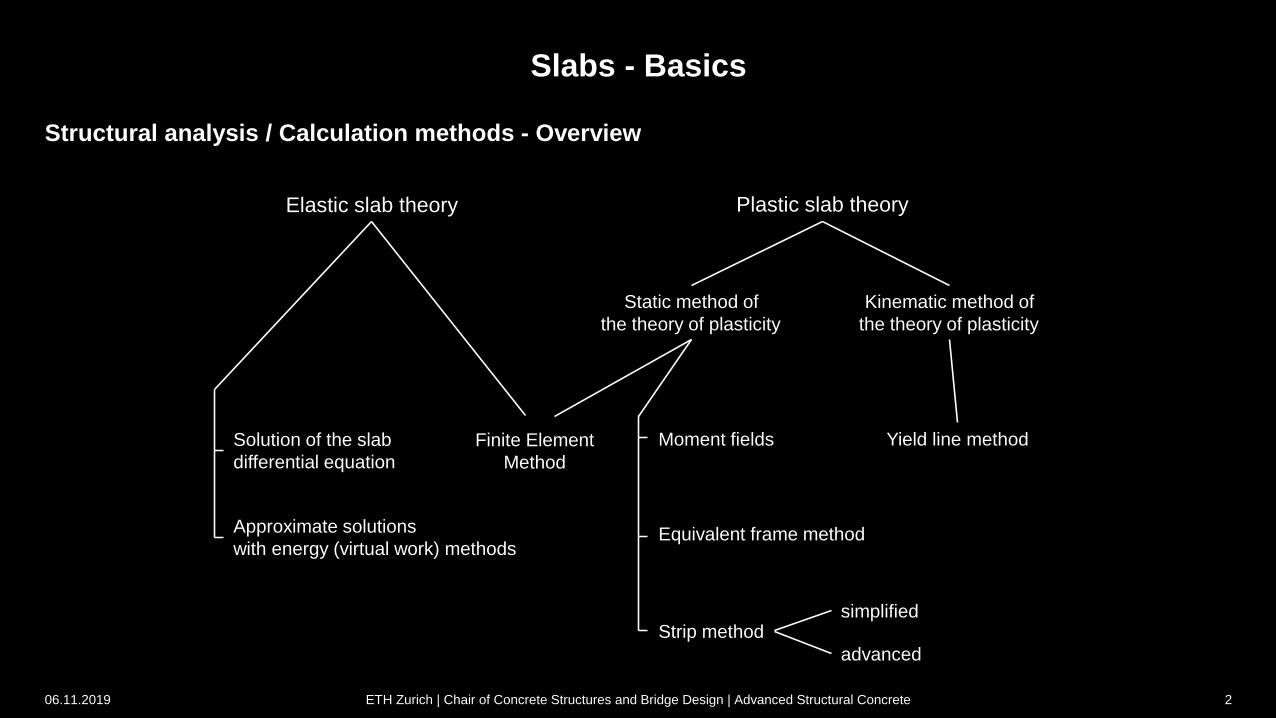
Structural analysis / Calculation methods - Overview
Slabs - Basics
Elastic slab theory Plastic slab theory
Solution of the slab
differential equation
Finite Element
Method
Approximate solutions
with energy (virtual work) methods
Static method of
the theory of plasticity
Kinematic method of
the theory of plasticity
Moment fields
Equivalent frame method
Strip method
Yield line method
simplified
advanced
06.11.2019 ETH Zurich | Chair of Concrete Structures and Bridge Design | Advanced Structural Concrete 2

x dz
yx dz
zx dzxy dz
y dz
zy dz
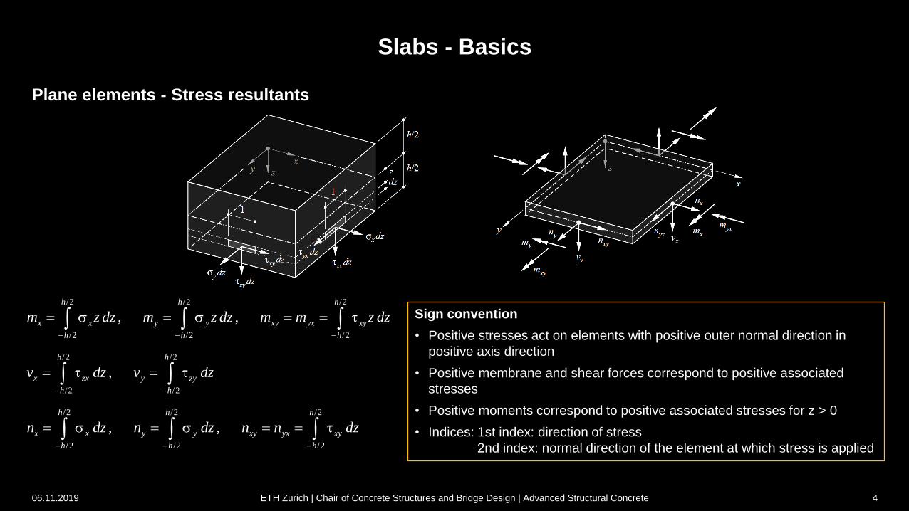
Plane elements - Stress resultants
Slabs - Basics
Bending stress
state (slab):
bending moments and
shear forces
Membrane stress
state (membrane element):
membrane forces
(normal/shear forces)
/2 /2 /2
/2 /2 /2
, , kNm/m = kN
h h h
x y xy yx
h h h
xyyxm z dz m z dz m m z dz
/2 /2
/2 /2
, kN/m
h h
x y
h h
zx zyv dz v dz
/2 /2 /2
/2 /2 /2
, , kN/m
h h h
x y xy yx
h h
yx
h
xyn dz n dz n n dz
xym
ymxm yxm
xn
xynxv
yvxyn
yn
06.11.2019 ETH Zurich | Chair of Concrete Structures and Bridge Design | Advanced Structural Concrete 3
Plane elements - Stress resultants
Slabs - Basics
06.11.2019 ETH Zurich | Chair of Concrete Structures and Bridge Design | Advanced Structural Concrete 4
/2 /2 /2
/2 /2 /2
, ,
h h h
x x y y xy yx xy
h h h
m z dz m z dz m m z dz
/2 /2
/2 /2
,
h h
x zx y zy
h h
v dz v dz
/2 /2 /2
/2 /2 /2
, ,
h h h
x x y y xy yx xy
h h h
n dz n dz n n dz
Sign convention
• Positive stresses act on elements with positive outer normal direction in
positive axis direction
• Positive membrane and shear forces correspond to positive associated
stresses
• Positive moments correspond to positive associated stresses for z > 0
• Indices: 1st index: direction of stress
2nd index: normal direction of the element at which stress is applied
3 Slabs
In-depth study and additions to Stahlbeton II
3.1 Equilibrium conditions
06.11.2019 ETH Zurich | Chair of Concrete Structures and Bridge Design | Advanced Structural Concrete 5
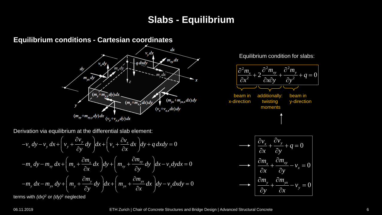
Slabs - Equilibrium
0yx
vvq
x y
0xyx
x
mmv
x y
0y yx
y
m mv
y x
beam in
x-direction
beam in
y-direction
additionally:
twisting
moments
2 22
2 22 0
xy yxm mm
qx x y y
0y x
x y y x
v vv dy v dx v dy dx v dx dy q dxdy
y x
0xyx
x xy x xy x
mmm dy m dx m dx dy m dy dx v dydx
x y
0y yx
y yx y yx y
m mm dx m dy m dy dx m dx dy v dxdy
y x
Equilibrium condition for slabs:
Derivation via equilibrium at the differential slab element:
terms with (dx)2 or (dy)2 neglected
Equilibrium conditions - Cartesian coordinates
06.11.2019 ETH Zurich | Chair of Concrete Structures and Bridge Design | Advanced Structural Concrete 6

Slabs - Equilibrium
06.11.2019 ETH Zurich | Chair of Concrete Structures and Bridge Design | Advanced Structural Concrete 7
Bending and twisting moments in any direction j: Principal direction j1 (twisting moments = 0) and principal
moments ( Mohr's circle):2 2cos sin sin 2n x y xym m m m j j j
2 2sin cos sin 2t x y xym m m m j j j
sin cos cos 2tn y x xym m m m j j j
1
2tan 2
xy
x y
m
m mj
2
2
1,2
4
2 2
x y xyx ym m mm m
m
2 2sin 2 2sin cos , cos 2 cos sinj j j j j jNB:
Stress transformation: Bending and twisting moments
Principal shear force and associated direction j0
(interpretation with Thales’ circle):
(generally j0 j1)
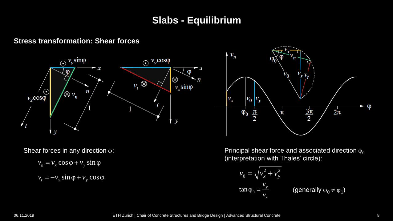
Slabs - Equilibrium
Shear forces in any direction j:
Stress transformation: Shear forces
cos sinn x yv v v j j
sin cost x yv v v j j2 2
0 x yv v v
0tany
x
v
vj
06.11.2019 ETH Zurich | Chair of Concrete Structures and Bridge Design | Advanced Structural Concrete 8
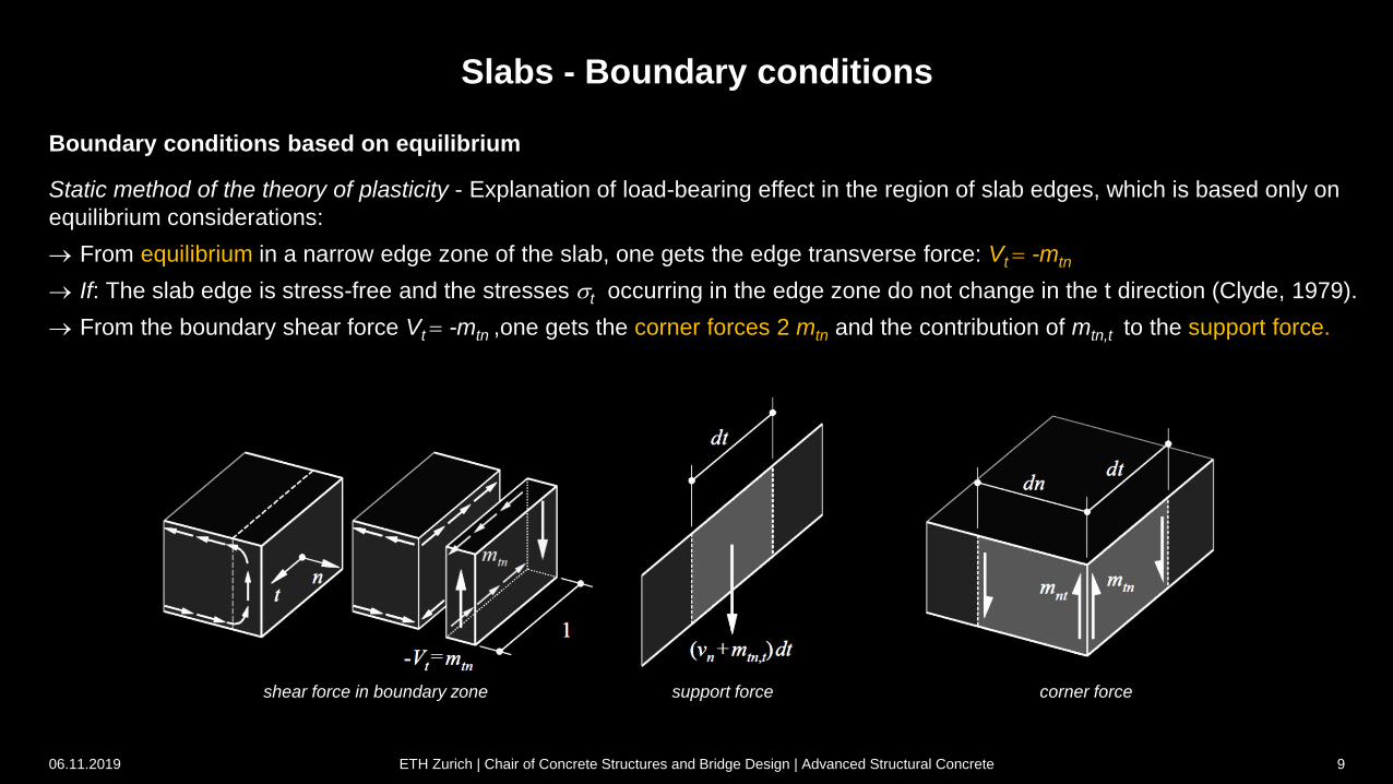
support force corner forceshear force in boundary zone
Static method of the theory of plasticity - Explanation of load-bearing effect in the region of slab edges, which is based only on
equilibrium considerations:
From equilibrium in a narrow edge zone of the slab, one gets the edge transverse force: Vt -mtn
If: The slab edge is stress-free and the stresses t occurring in the edge zone do not change in the t direction (Clyde, 1979).
From the boundary shear force Vt -mtn ,one gets the corner forces 2 mtn and the contribution of mtn,t to the support force.
Slabs - Boundary conditions
06.11.2019 ETH Zurich | Chair of Concrete Structures and Bridge Design | Advanced Structural Concrete 9
Boundary conditions based on equilibrium
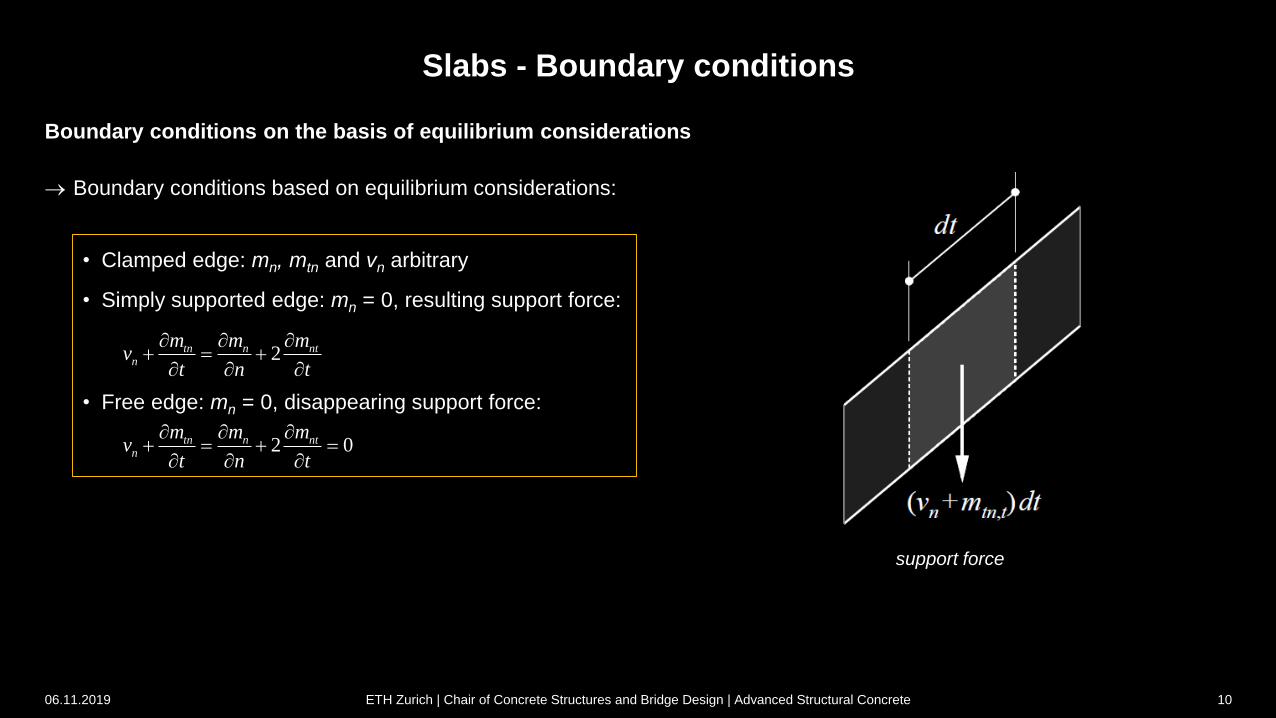
Boundary conditions based on equilibrium considerations:
support force
Slabs - Boundary conditions
06.11.2019 ETH Zurich | Chair of Concrete Structures and Bridge Design | Advanced Structural Concrete 10
Boundary conditions on the basis of equilibrium considerations
• Clamped edge: mn, mtn and vn arbitrary
• Simply supported edge: mn = 0, resulting support force:
• Free edge: mn = 0, disappearing support force:
2tn n ntn
m m mv
t n t
2 0tn n ntn
m m mv
t n t
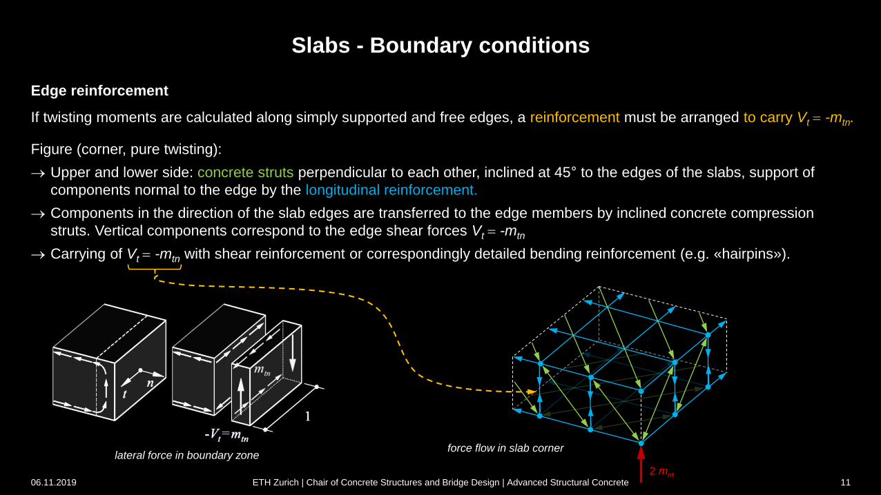
lateral force in boundary zoneforce flow in slab corner
Slabs - Boundary conditions
Edge reinforcement
If twisting moments are calculated along simply supported and free edges, a reinforcement must be arranged to carry Vt -mtn.
Figure (corner, pure twisting):
Upper and lower side: concrete struts perpendicular to each other, inclined at 45° to the edges of the slabs, support of
components normal to the edge by the longitudinal reinforcement.
Components in the direction of the slab edges are transferred to the edge members by inclined concrete compression
struts. Vertical components correspond to the edge shear forces Vt -mtn
Carrying of Vt -mtn with shear reinforcement or correspondingly detailed bending reinforcement (e.g. «hairpins»).
2 mnt06.11.2019 ETH Zurich | Chair of Concrete Structures and Bridge Design | Advanced Structural Concrete 11
discontinuity line
Slabs - Boundary conditions
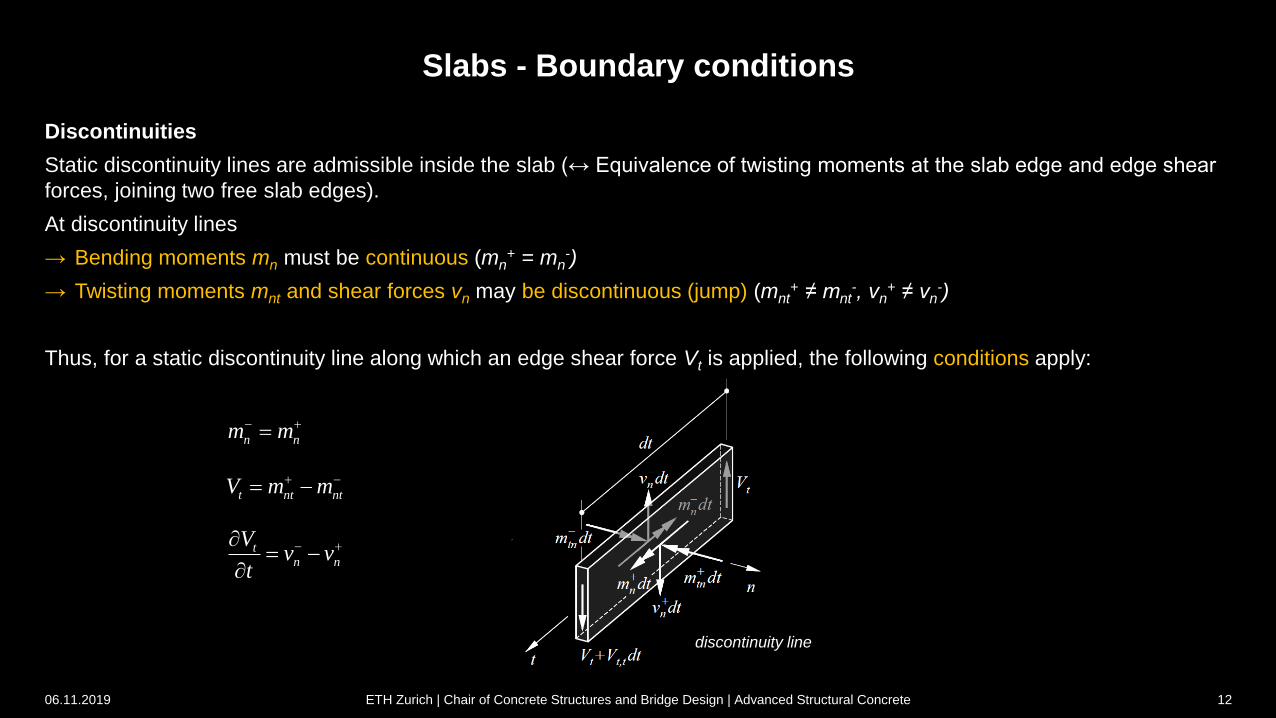
Discontinuities
Static discontinuity lines are admissible inside the slab (↔ Equivalence of twisting moments at the slab edge and edge shear
forces, joining two free slab edges).
At discontinuity lines
→ Bending moments mn must be continuous (mn+ = mn
-)
→ Twisting moments mnt and shear forces vn may be discontinuous (jump) (mnt+ ≠ mnt
-, vn+ ≠ vn
-)
Thus, for a static discontinuity line along which an edge shear force Vt is applied, the following conditions apply:
n nm m
t nt ntV m m
tn n
Vv v
t
06.11.2019 ETH Zurich | Chair of Concrete Structures and Bridge Design | Advanced Structural Concrete 12
3 Slabs
In-depth study and additions to Stahlbeton II
3.2 Yield conditions
06.11.2019 ETH Zurich | Chair of Concrete Structures and Bridge Design | Advanced Structural Concrete 13
Slabs - Yield conditions
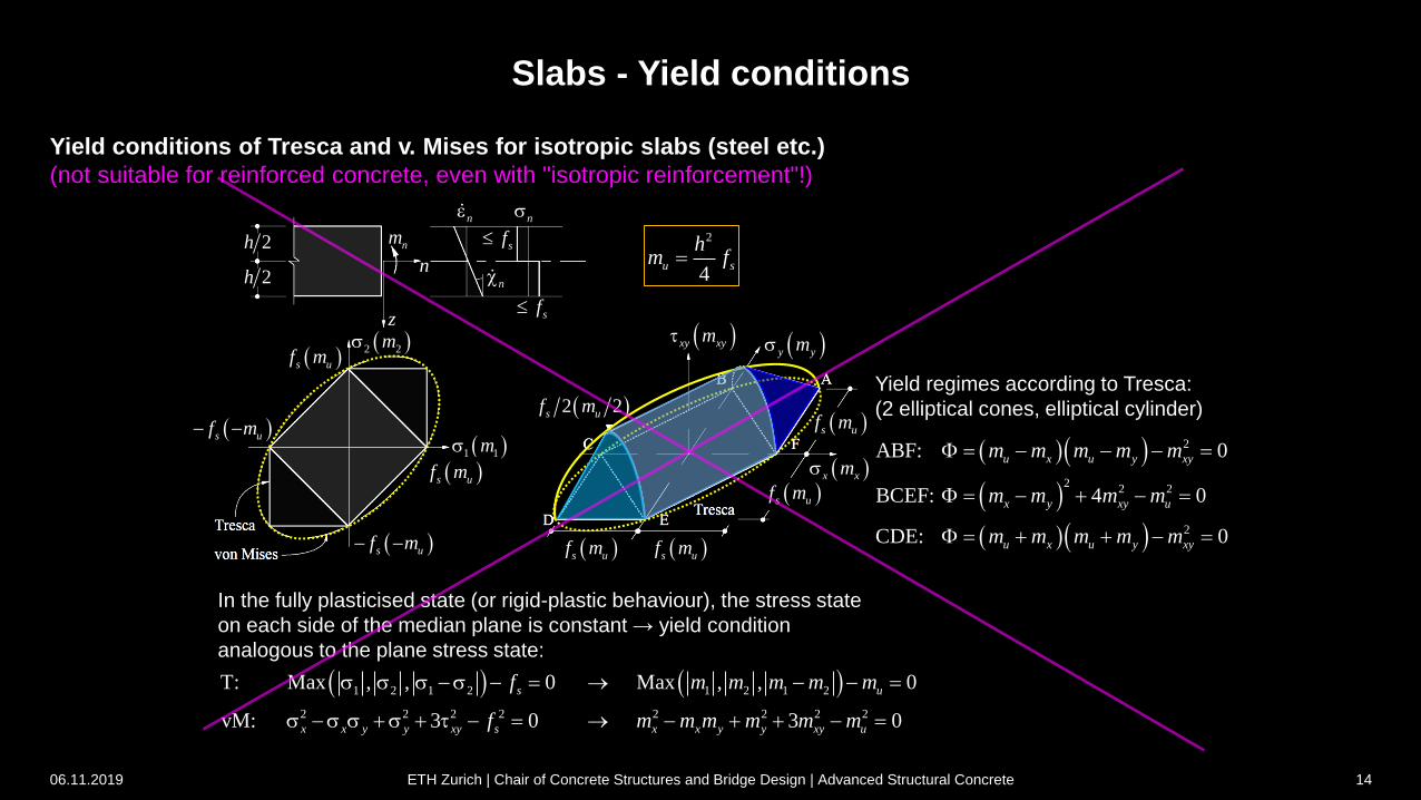
Yield conditions of Tresca and v. Mises for isotropic slabs (steel etc.)
(not suitable for reinforced concrete, even with "isotropic reinforcement"!)
In the fully plasticised state (or rigid-plastic behaviour), the stress state
on each side of the median plane is constant → yield condition
analogous to the plane stress state:
Yield regimes according to Tresca:
(2 elliptical cones, elliptical cylinder)
1 2 1 2 1 2 1 2
2 2 2 2 2 2 2 2
T: Max , , 0 Max , , 0
vM: 3 0 3 0
s u
x x y y xy s x x y y xy u
f m m m m m
f m m m m m m
2
22 2
2
ABF: 0
BCEF: 4 0
CDE: 0
u x u y xy
x y xy u
u x u y xy
m m m m m
m m m m
m m m m m
2
4u s
hm f
s uf m s uf m
s uf m
s uf m
x xm
y ym xy xym
2 2s uf m
1 1m
s uf m
s uf m
s uf m
s uf m 2 2m
sf
sf
n
nn
n
nm
z
2h
2h
06.11.2019 ETH Zurich | Chair of Concrete Structures and Bridge Design | Advanced Structural Concrete 14
Slabs - Yield conditions
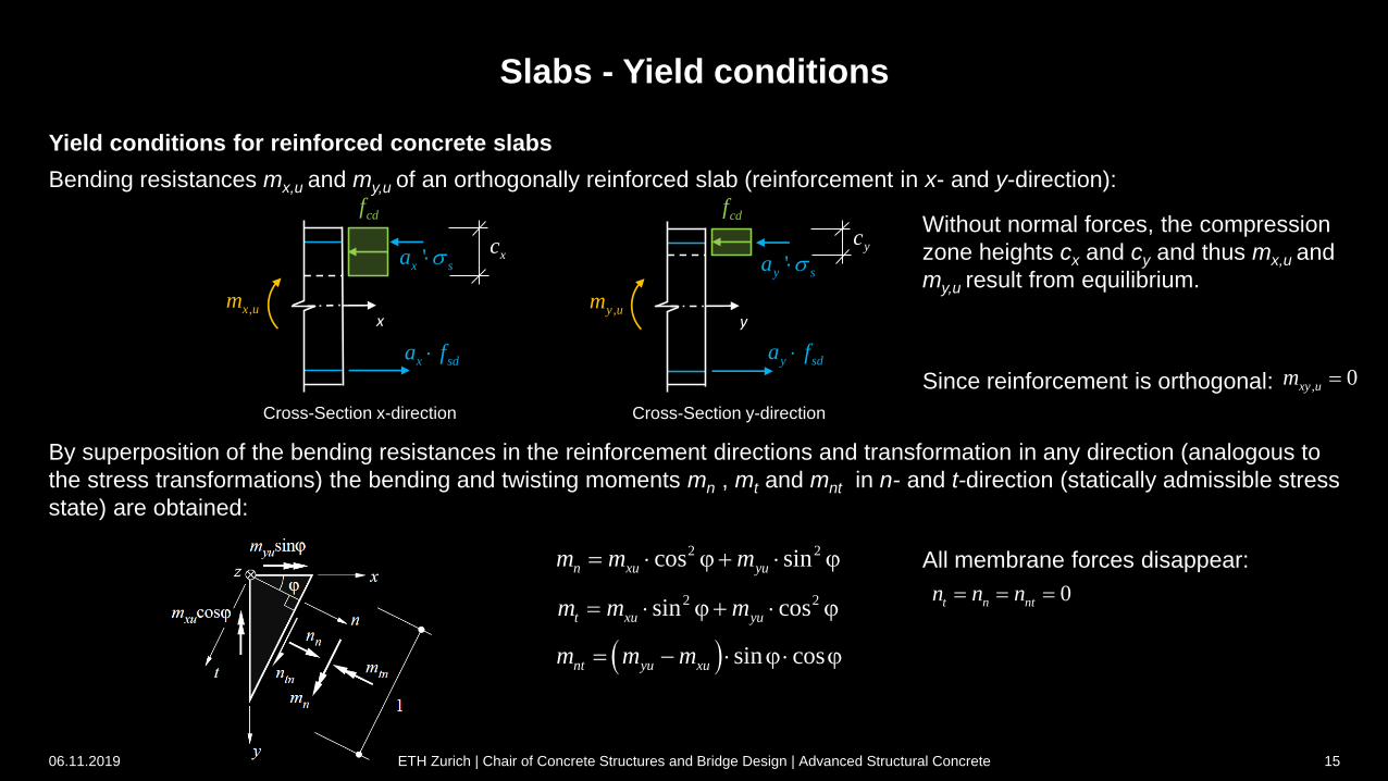
Yield conditions for reinforced concrete slabs
Bending resistances mx,u and my,u of an orthogonally reinforced slab (reinforcement in x- and y-direction):
By superposition of the bending resistances in the reinforcement directions and transformation in any direction (analogous to
the stress transformations) the bending and twisting moments mn , mt and mnt in n- and t-direction (statically admissible stress
state) are obtained:
Cross-Section x-direction Cross-Section y-direction
x sda f
'x sa
cdf
,x umx
xc
y sda f
'y sa
cdf
,y umy
ycWithout normal forces, the compression
zone heights cx and cy and thus mx,u and
my,u result from equilibrium.
Since reinforcement is orthogonal: , 0xy um
2 2cos sinn xu yum m m j j
sin cosnt yu xum m m j j
2 2sin cost xu yum m m j j
All membrane forces disappear:
0t n ntn n n
06.11.2019 ETH Zurich | Chair of Concrete Structures and Bridge Design | Advanced Structural Concrete 15
Slabs - Yield conditions
06.11.2019 ETH Zurich | Chair of Concrete Structures and Bridge Design | Advanced Structural Concrete 16
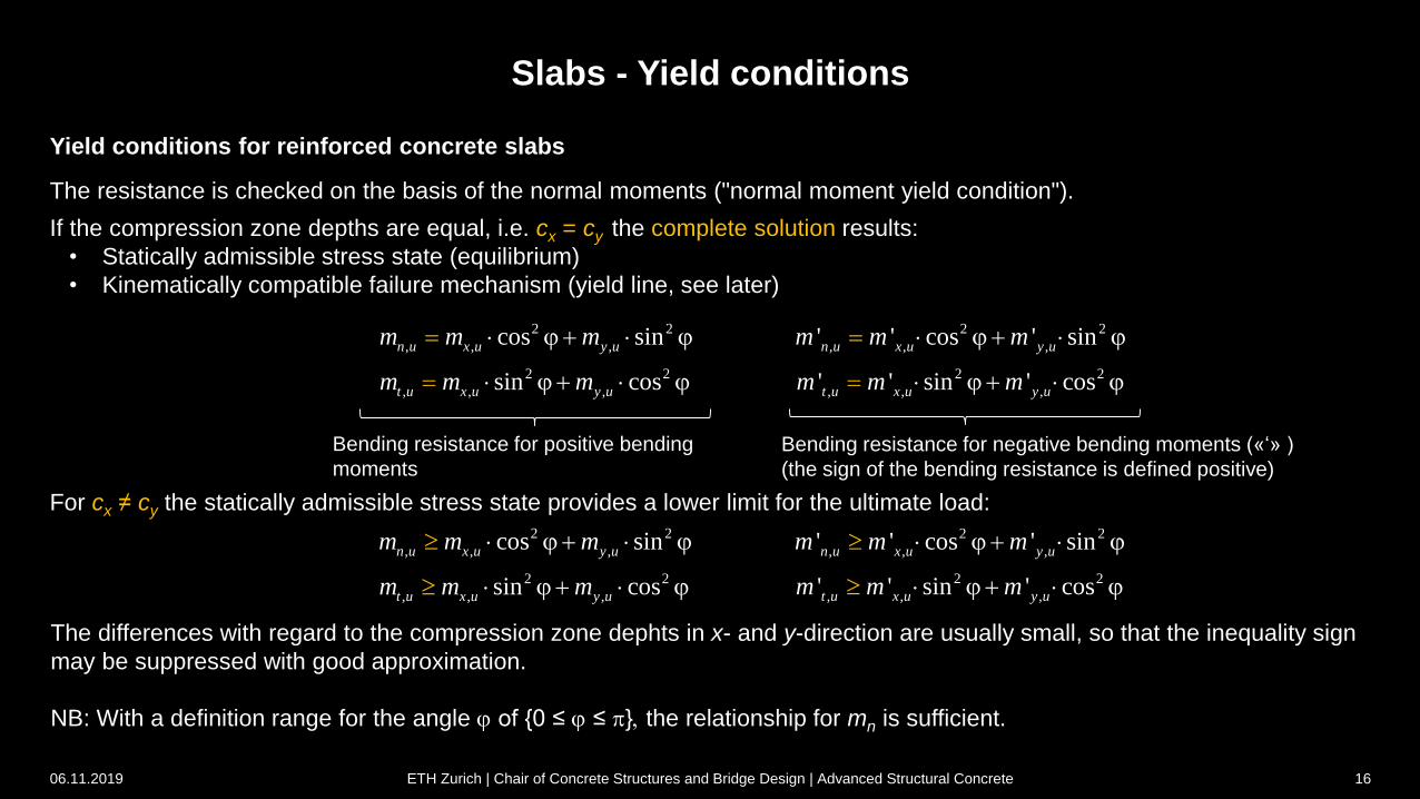
Yield conditions for reinforced concrete slabs
The resistance is checked on the basis of the normal moments ("normal moment yield condition").
If the compression zone depths are equal, i.e. cx = cy the complete solution results:
• Statically admissible stress state (equilibrium)
• Kinematically compatible failure mechanism (yield line, see later)
For cx ≠ cy the statically admissible stress state provides a lower limit for the ultimate load:
2 2
, , ,cos sinn u x u y um m m j j
2 2
, , ,sin cost u x u y um m m j j
2 2
, , ,' ' cos ' sinn u x u y um m m j j
2 2
, , ,' ' sin ' cost u x u y um m m j j
2 2
, , ,cos sinn u x u y um m m j j
2 2
, , ,sin cost u x u y um m m j j
2 2
, , ,' ' cos ' sinn u x u y um m m j j
2 2
, , ,' ' sin ' cost u x u y um m m j j
Bending resistance for positive bending
moments
Bending resistance for negative bending moments («‘» )
(the sign of the bending resistance is defined positive)
The differences with regard to the compression zone dephts in x- and y-direction are usually small, so that the inequality sign
may be suppressed with good approximation.
NB: With a definition range for the angle j of {0 ≤ j ≤ p}, the relationship for mn is sufficient.
Slabs - Yield conditions
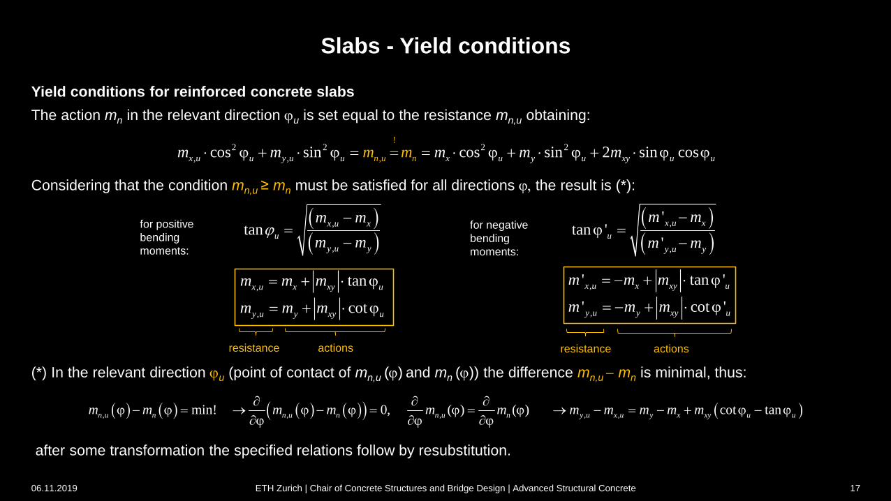
Yield conditions for reinforced concrete slabs
The action mn in the relevant direction ju is set equal to the resistance mn,u obtaining:
Considering that the condition mn,u ≥ mn must be satisfied for all directions j, the result is (*):
(*) In the relevant direction ju (point of contact of mn,u (j) and mn (j)) the difference mn,u mn is minimal, thus:
after some transformation the specified relations follow by resubstitution.
!2 2 2 2
, ,,cos sin cos sin 2 sin cosx u u y u u x u y u un xy un umm m m m mm j j j j j j
for positive
bending
moments:
, tanx u x xy um m m j
, coty u y xy um m m j
,
,
tanx u x
u
y u y
m m
m mj
,' cot 'y u y xy um m m j
,' tan 'x u x xy um m m j
,
,
'tan '
'
x u x
u
y u y
m m
m m
j
for negative
bending
moments:
resistance actions resistance actions
, , , , ,min! 0, ( ) ( ) cot tann u n n u n n u n y u x u y x xy u um m m m m m m m m m m
j j j j j j j jj j j
06.11.2019 ETH Zurich | Chair of Concrete Structures and Bridge Design | Advanced Structural Concrete 17
nm
,'n um
,n um
Slabs - Yield conditions
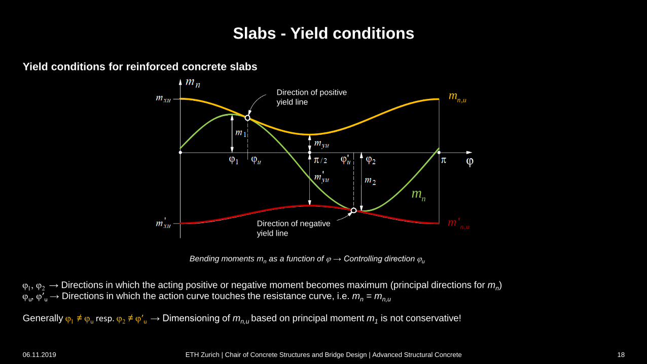
Yield conditions for reinforced concrete slabs
Bending moments mn as a function of j → Controlling direction ju
j1, j2 → Directions in which the acting positive or negative moment becomes maximum (principal directions for mn)ju, j’u → Directions in which the action curve touches the resistance curve, i.e. mn = mn,u
Generally j1 ≠ ju resp. j2 ≠ j’u → Dimensioning of mn,u based on principal moment m1 is not conservative!
06.11.2019 ETH Zurich | Chair of Concrete Structures and Bridge Design | Advanced Structural Concrete 18
Direction of positive
yield line
Direction of negative
yield line
0Y
' 0Y
Slabs - Yield conditions
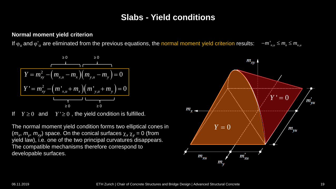
Normal moment yield criterion
If ju and j’u are eliminated from the previous equations, the normal moment yield criterion results:
2
, , 0xy x u x y u yY m m m m m
2
, ,' ' ' 0xy x u x y u yY m m m m m
≥ 0 ≥ 0
≥ 0 ≥ 0
If and , the yield condition is fulfilled. 0Y ' 0Y
The normal moment yield condition forms two elliptical cones in
(mx, my, mxy) space. On the conical surfaces x y = 0 (from
yield law), i.e. one of the two principal curvatures disappears.
The compatible mechanisms therefore correspond to
developable surfaces.
, ,'n u n n um m m
06.11.2019 ETH Zurich | Chair of Concrete Structures and Bridge Design | Advanced Structural Concrete 19
Slabs - Yield conditions
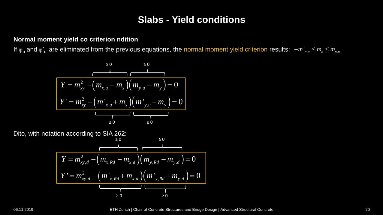
Normal moment yield co criterion ndition
If ju and j’u are eliminated from the previous equations, the normal moment yield criterion results:
2
, , 0xy x u x y u yY m m m m m
2
, ,' ' ' 0xy x u x y u yY m m m m m
≥ 0 ≥ 0
≥ 0 ≥ 0
Dito, with notation according to SIA 262:
, ,'n u n n um m m
2
, , , , , 0xy d x Rd x d y Rd y dY m m m m m
2
, , , , ,' ' ' 0xy d x Rd x d y Rd y dY m m m m m
≥ 0 ≥ 0
≥ 0 ≥ 0
06.11.2019 ETH Zurich | Chair of Concrete Structures and Bridge Design | Advanced Structural Concrete 20
1k
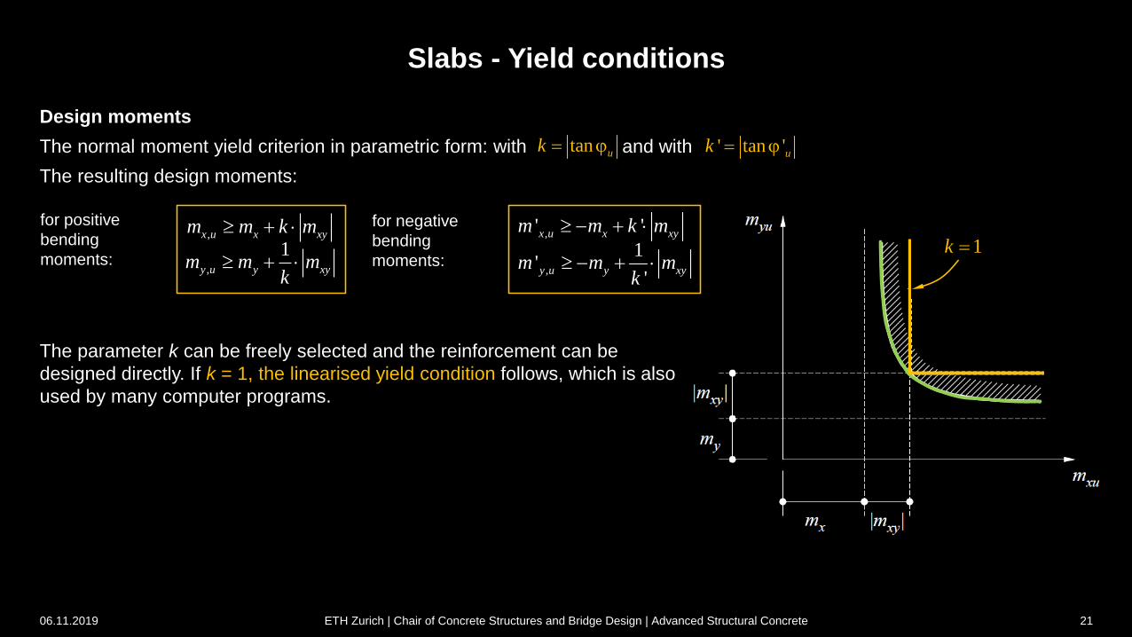
Slabs - Yield conditions
The parameter k can be freely selected and the reinforcement can be
designed directly. If k = 1, the linearised yield condition follows, which is also
used by many computer programs.
,x u x xym m k m
,
1y u y xym m m
k
,
1'
'y u y xym m m
k
,' 'x u x xym m k m for positive
bending
moments:
for negative
bending
moments:
06.11.2019 ETH Zurich | Chair of Concrete Structures and Bridge Design | Advanced Structural Concrete 21
Design moments
The normal moment yield criterion in parametric form: with and with
The resulting design moments:
tan uk j ' tan 'uk j
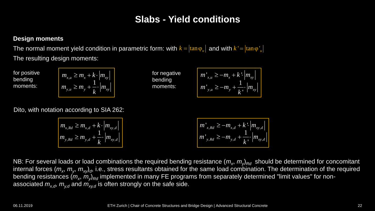
Slabs - Yield conditions
Design moments
The normal moment yield condition in parametric form: with and with
The resulting design moments:
,x u x xym m k m
,
1y u y xym m m
k
,' 'x u x xym m k m for positive
bending
moments:
for negative
bending
moments:
NB: For several loads or load combinations the required bending resistance (mx, my)Rd should be determined for concomitant
internal forces (mx, my, mxy)d, i.e., stress resultants obtained for the same load combination. The determination of the required
bending resistances (mx, my)Rd implemented in many FE programs from separately determined "limit values" for non-
associated mx,d, my,d and mxy,d is often strongly on the safe side.
, , ,x Rd x d xy dm m k m
, , ,
1y Rd y d xy dm m m
k , , ,
1'
'y Rd y d xy dm m m
k
, , ,' 'x Rd x d xy dm m k m
Dito, with notation according to SIA 262:
06.11.2019 ETH Zurich | Chair of Concrete Structures and Bridge Design | Advanced Structural Concrete 22
,
1'
'y u y xym m m
k
tan uk j ' tan 'uk j
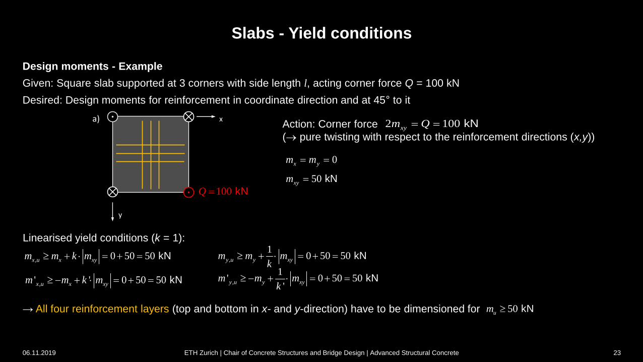
Slabs - Yield conditions
Design moments - Example
Given: Square slab supported at 3 corners with side length l, acting corner force Q = 100 kN
Desired: Design moments for reinforcement in coordinate direction and at 45° to it
100 kNQ
a) x
y
Linearised yield conditions (k = 1):
, 0 50 50 kNx u x xym m k m ,
10 50 50 kNy u y xym m m
k
,' ' 0 50 50 kNx u x xym m k m ,
1' 0 50 50
' kNy u y xym m m
k
→ All four reinforcement layers (top and bottom in x- and y-direction) have to be dimensioned for 50 kNum
Action: Corner force
( pure twisting with respect to the reinforcement directions (x,y))
2 100xym Q kN
0x ym m
50xym kN
06.11.2019 ETH Zurich | Chair of Concrete Structures and Bridge Design | Advanced Structural Concrete 23
100 kNQ
x
y
t
n
Slabs - Yield conditions
Design moments - Example
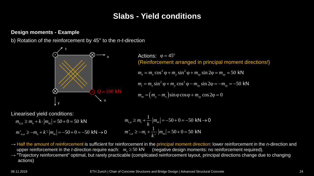
b) Rotation of the reinforcement by 45° to the n-t-direction
, 50 0 50 kNn u n ntm m k m ,
150 0 50 kN 0t u t ntm m m
k
,' ' 50 0 50 kN 0n u n ntm m k m ,
1' 50 0 50
' kNt u t ntm m m
k
→ Half the amount of reinforcement is sufficient for reinforcement in the principal moment direction: lower reinforcement in the n-direction and
upper reinforcement in the t-direction require each: (negative design moments: no reinforcement required).
→ "Trajectory reinforcement" optimal, but rarely practicable (complicated reinforcement layout, principal directions change due to changing actions)
50 kNum
2 2cos sin sin 2 50n x y xy xym m m m m j j j kN
Actions:
(Reinforcement arranged in principal moment directions!)
2 2sin cos sin 2 50t x y xy xym m m m m j j j kN
sin cos cos 2 0nt y x xym m m m j j j
45j
Linearised yield conditions:
06.11.2019 ETH Zurich | Chair of Concrete Structures and Bridge Design | Advanced Structural Concrete 24
Slabs - Yield conditions
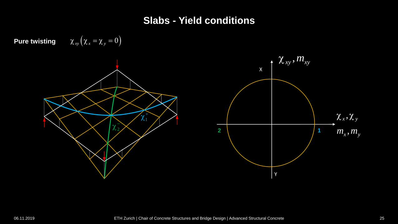
Pure twisting
X
Y
2 1
,xy xym
,
,
x y
x ym m
0xy x y
2
1
06.11.2019 ETH Zurich | Chair of Concrete Structures and Bridge Design | Advanced Structural Concrete 25
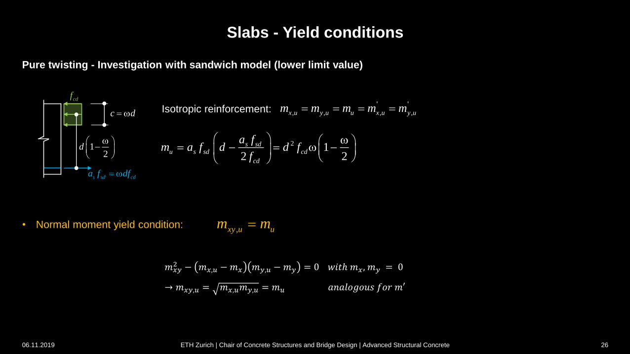
Slabs - Yield conditions
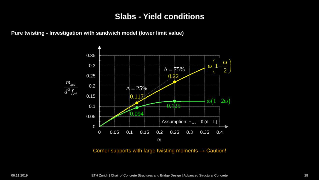
Pure twisting - Investigation with sandwich model (lower limit value)
, , , ,
' 'x u y u u x u y um m m m m Isotrop bewehrt:
2 12 2
s sdu s sd cd
cd
a fm a f d d f
f
• Normal moment yield condition:,xy u um m
06.11.2019 ETH Zurich | Chair of Concrete Structures and Bridge Design | Advanced Structural Concrete 26
s sd cda f df
cdf
c d
12
d
Isotropic reinforcement:
𝑚𝑥𝑦2 − 𝑚𝑥,𝑢 −𝑚𝑥 𝑚𝑦,𝑢 −𝑚𝑦 = 0 𝑤𝑖𝑡ℎ 𝑚𝑥 , 𝑚𝑦 = 0
→ 𝑚𝑥𝑦,𝑢 = 𝑚𝑥,𝑢𝑚𝑦,𝑢 = 𝑚𝑢 𝑎𝑛𝑎𝑙𝑜𝑔𝑜𝑢𝑠 𝑓𝑜𝑟 𝑚′
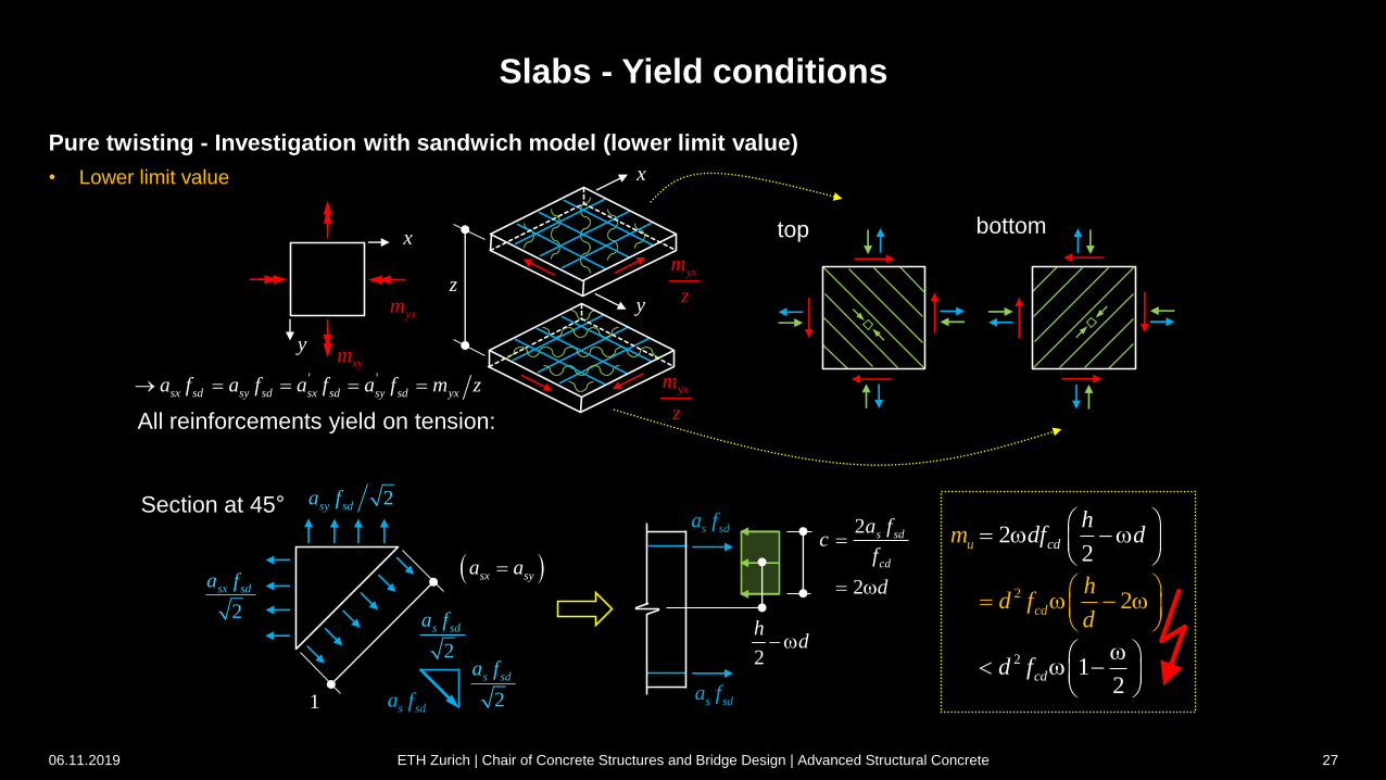
Slabs - Yield conditions
Pure twisting - Investigation with sandwich model (lower limit value)
• Lower limit value
xym
yxm
x
y
yxm
z
yxm
z
x
z
oben unten
' 'sx sd sy sd sx sd sy sd yxa f a f a f a f m z
d.h. alle Bewehrungen fliessen auf Zug!
1
2sy sda f
sx sya a
s sda f
2
2
s sd
cd
a fc
f
d
2
hd
s sda f
2
2
2
22
12
cd
cd
u
cd
m
hd f
d
hdf d
d f
s sda f
2
s sda f2
sx sda f
2
s sda f
y
06.11.2019 ETH Zurich | Chair of Concrete Structures and Bridge Design | Advanced Structural Concrete 27
All reinforcements yield on tension:
Section at 45°
top bottom
Slabs - Yield conditions
Pure twisting - Investigation with sandwich model (lower limit value)
0
0.05
0.1
0.15
0.2
0.25
0.3
0.35
0 0.05 0.1 0.15 0.2 0.25 0.3 0.35 0.4
2
xyu
cd
m
d f
Corner supports with large twisting moments → Caution!
Assumption: cnom = 0 (d = h)
1 2
12
0.125
0.117
0.094
25%
75%
0.22
06.11.2019 ETH Zurich | Chair of Concrete Structures and Bridge Design | Advanced Structural Concrete 28
xv xm
xymyxn
xn
xynyn
yv
xym
ym
z
yvxv
2 2 tan
xy xy x y
o
m n v v
z v
2
x xm n
z 2
02 tan
xv
v
z
2
02 tan
yv
v
2
y ym n
z
2
2 2 tan
y y y
o
m n v
z v
2 2 tan
xy xy x y
o
m n v v
z v
2
2 2 tan
x x x
o
m n v
z v
2 2
0 x yv v v
1
0 tan ( )y xv vj
x
y z
0v
0 cotv
0 cot
2
v cotz
0 cot
2
v
z
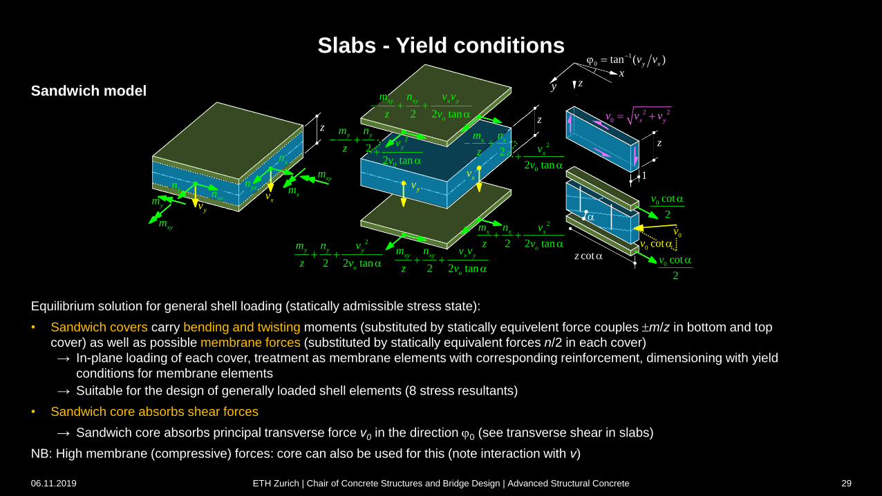
Slabs - Yield conditions
Equilibrium solution for general shell loading (statically admissible stress state):
• Sandwich covers carry bending and twisting moments (substituted by statically equivelent force couples m/z in bottom and top
cover) as well as possible membrane forces (substituted by statically equivalent forces n/2 in each cover)
→ In-plane loading of each cover, treatment as membrane elements with corresponding reinforcement, dimensioning with yield
conditions for membrane elements
→ Suitable for the design of generally loaded shell elements (8 stress resultants)
• Sandwich core absorbs shear forces
→ Sandwich core absorbs principal transverse force v0 in the direction j0 (see transverse shear in slabs)
NB: High membrane (compressive) forces: core can also be used for this (note interaction with v)
06.11.2019 ETH Zurich | Chair of Concrete Structures and Bridge Design | Advanced Structural Concrete 29
Sandwich model

yvxym
ym
z
xv xmxym
yvxv
xm
z
ym
z
ym
z
xm
z
z
2 2
0 x yv v v
1
0 tan ( )y xv vj
x
y z
z
xym
z
xym
zxym
z
xym
z
Slabs - Yield conditions
Slabs under pure bending without shear reinforcement:
nx = ny = nxy = 0, v0d ≤ vRd = kd cd dv
Terms with nx, ny, nxy are zero
Terms with vx, vy are omitted if an uncracked core is assumed.
Yield conditions for slabs based on the sandwich model = simplification of the general case of a shell element with eight stress resultants
(slab: only bending and twisting moments considered, consideration of transverse (slab) shear forces → see shear force in slabs)
06.11.2019 ETH Zurich | Chair of Concrete Structures and Bridge Design | Advanced Structural Concrete 30
Sandwich model
Slabs - Yield conditions
yvxym
ym
z
xv xmxym
yvxv
xym
z
xm
z
ym
z
xym
zym
z
xm
z
z
2 2
0 x yv v v
1
0 tan ( )y xv vj
x
y z
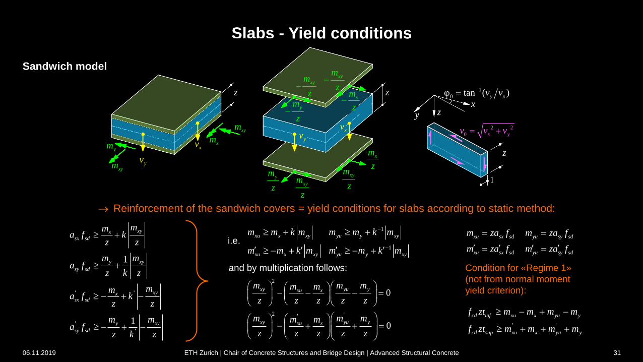
z
Reinforcement of the sandwich covers = yield conditions for slabs according to static method:
' '
'
'
1
1
xyxsx sd
y xy
sy sd
xyxsx sd
y xy
sy sd
mma f k
z z
m ma f
z k z
mma f k
z z
m ma f
z k z
xym
z
xym
z
xu sx sd yu sy sd
xu sx sd yu sy sd
m za f m za f
m za f m za f
1
1
xu x xy yu y xy
xu x xy yu y xy
m m k m m m k m
m m k m m m k m
i.e.
2
2 ''
0
0
xy yu yxu x
xy yu yxu x
m m mm m
z z z z z
m m mm m
z z z z z
and by multiplication follows: Condition for «Regime 1»
(not from normal moment
yield criterion):
' '
cd inf xu x yu y
cd sup xu x yu y
f zt m m m m
f zt m m m m
06.11.2019 ETH Zurich | Chair of Concrete Structures and Bridge Design | Advanced Structural Concrete 31
Sandwich model
sinxym j
sinym jx
k
z
t
cosxm j
cosyxm j
y
1
k
kum
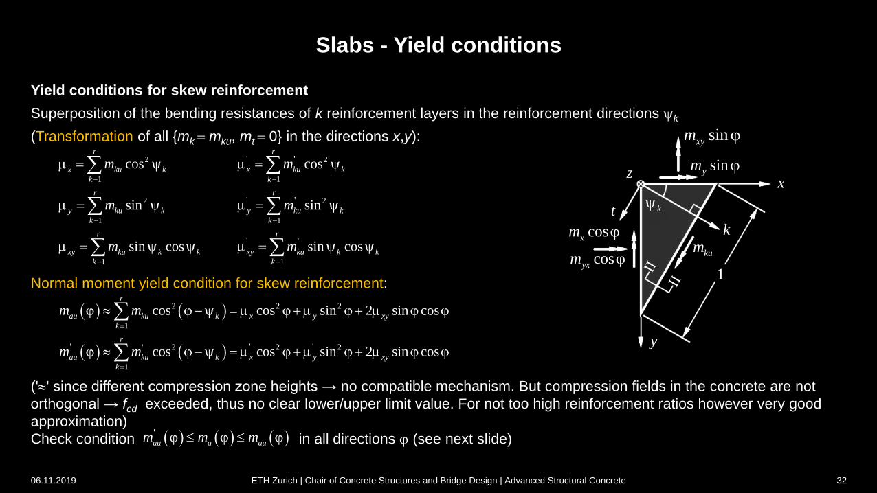
Slabs - Yield conditions
Yield conditions for skew reinforcement
Superposition of the bending resistances of k reinforcement layers in the reinforcement directions k
(Transformation of all {mk mku, mt 0} in the directions x,y):
Normal moment yield condition for skew reinforcement:
('' since different compression zone heights → no compatible mechanism. But compression fields in the concrete are not
orthogonal → fcd exceeded, thus no clear lower/upper limit value. For not too high reinforcement ratios however very good
approximation)
Check condition in all directions j (see next slide)
2 2
1 1
2 2
1 1
1 1
' '
' '
' '
cos cos
sin sin
sin cos sin cos
r r
x ku k x ku k
k k
r r
y ku k y ku k
k k
r r
xy ku k k xy ku k k
k k
m m
m m
m m
2 2 2
1
' 2 2 2
1
' ' '
cos cos sin 2 sin cos
cos cos sin 2 sin cos
r
au ku k x y xy
k
r
au ku k x y xy
k
m m
m m
j j j j j j
j j j j j j
'au a aum m mj j j
06.11.2019 ETH Zurich | Chair of Concrete Structures and Bridge Design | Advanced Structural Concrete 32
2p
aum
am
,aum
2mau ag m m
2p
j p
1m
1j uj
600
0
600
0
Slabs - Yield conditions
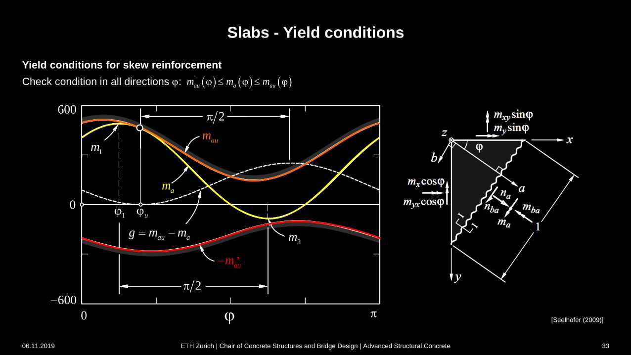
Yield conditions for skew reinforcement
Check condition in all directions j:
[Seelhofer (2009)]
'au a aum m mj j j
06.11.2019 ETH Zurich | Chair of Concrete Structures and Bridge Design | Advanced Structural Concrete 33
Slabs - Yield conditions
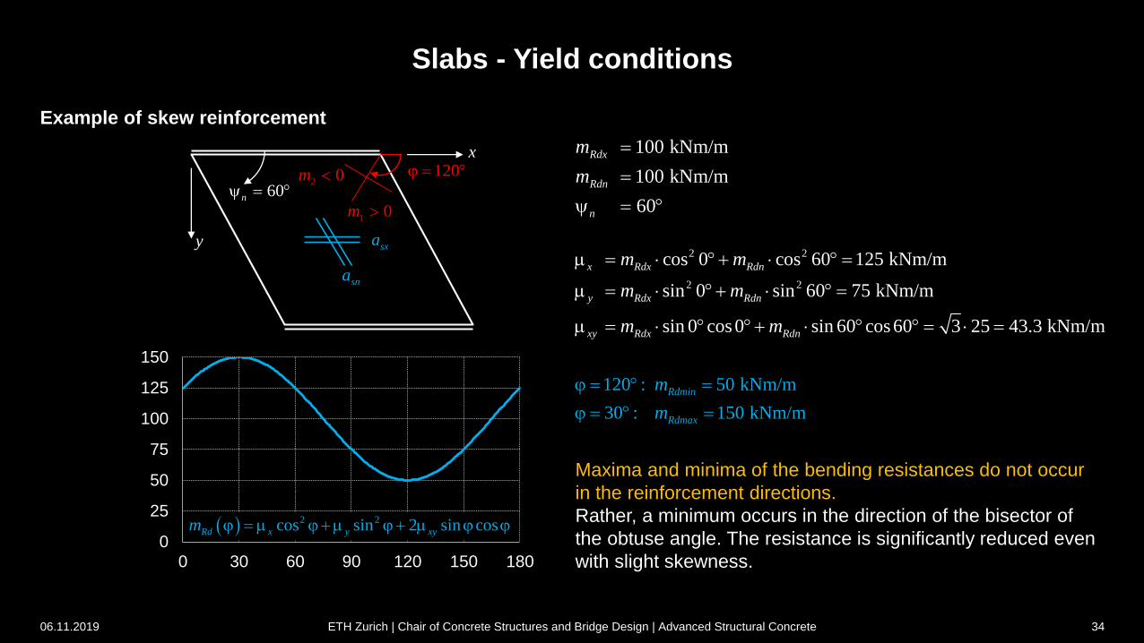
Example of skew reinforcement
x
y
60n
sna
sxa
120j 2 0m
100 kNm/m
100 kNm/m
60
Rdx
Rdn
n
m
m
2 2
2 2
cos 0 cos 60 125 kNm/m
sin 0 sin 60 75 kNm/m
sin 0 cos0 sin 60 cos60 3 25 43.3 kNm/m
x Rdx Rdn
y Rdx Rdn
xy Rdx Rdn
m m
m m
m m
0
25
50
75
100
125
150
0 30 60 90 120 150 180
120 : 50 kNm/m
30 : 150 kNm/m
Rdmin
Rdmax
m
m
j
j
2 2cos sin 2 sin cosRd x y xym j j j j j
Maxima and minima of the bending resistances do not occur
in the reinforcement directions.
Rather, a minimum occurs in the direction of the bisector of
the obtuse angle. The resistance is significantly reduced even
with slight skewness.
1 0m
06.11.2019 ETH Zurich | Chair of Concrete Structures and Bridge Design | Advanced Structural Concrete 34
1
,x
m
m
y
1
,n
mm
Slabs - Yield conditions
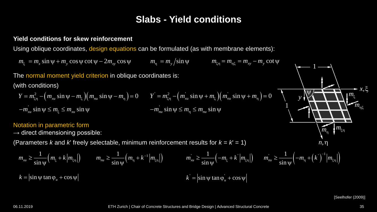
Yield conditions for skew reinforcement
Using oblique coordinates, design equations can be formulated (as with membrane elements):
The normal moment yield criterion in oblique coordinates is:
(with conditions)
Notation in parametric form
→ direct dimensioning possible:
(Parameters k and k' freely selectable, minimum reinforcement results for k = k' = 1)
sin cos cot 2 cosx y xym m m m
2 sin sin 0xu nuY m m m m m
[Seelhofer (2009)]
11 1
sin sinxu num m k m m m k m
06.11.2019 ETH Zurich | Chair of Concrete Structures and Bridge Design | Advanced Structural Concrete 35
cotxy ym m m m sinym m
' sin sinxu xum m m
sin tan cosuk j
2' ' 'sin sin 0xu nuY m m m m m
' sin sinnu num m m
1' ' ' '1 1
sin sinxu num m k m m m k m
' 'sin tan cosuk j
Slabs - Yield conditions
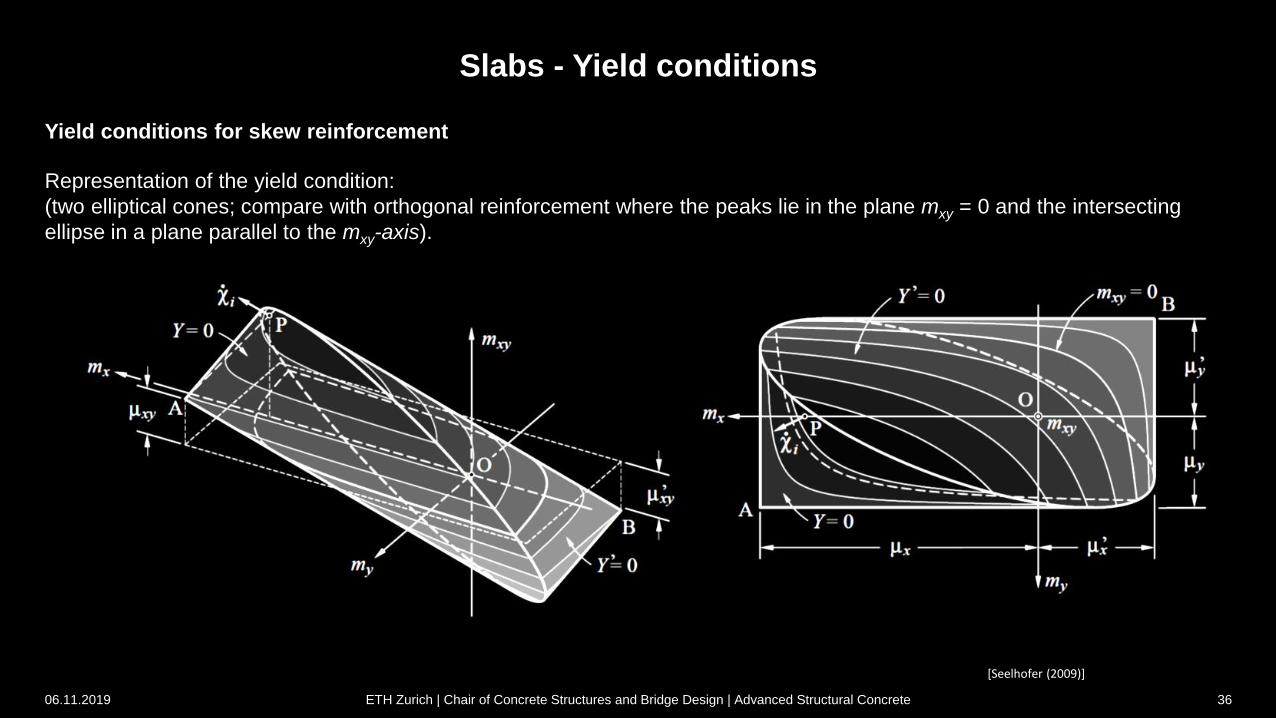
Yield conditions for skew reinforcement
Representation of the yield condition:
(two elliptical cones; compare with orthogonal reinforcement where the peaks lie in the plane mxy = 0 and the intersecting
ellipse in a plane parallel to the mxy-axis).
[Seelhofer (2009)]
06.11.2019 ETH Zurich | Chair of Concrete Structures and Bridge Design | Advanced Structural Concrete 36
Slabs - Yield conditions
skew reinforcement
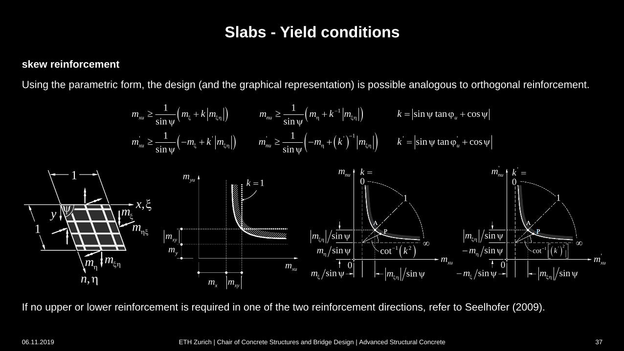
Using the parametric form, the design (and the graphical representation) is possible analogous to orthogonal reinforcement.
[Seelhofer (2009)]
If no upper or lower reinforcement is required in one of the two reinforcement directions, refer to Seelhofer (2009).
1
,x
m
m
y
1
,n
mm
yum1k
xym
ym
xm xym
xumsinm
0
sinm
sinm
1 2cot k
sinm
xum
0k num
1
sinm 0
sinm
sinm
2
1 'cot k
sinm
'xum
'
0k
'num
1
1
1' ' ' ' ' '
1 1sin tan cos
sin sin
1 1sin tan cos
sin sin
xu nu u
xu nu u
m m k m m m k m k
m m k m m m k m k
j
j
06.11.2019 ETH Zurich | Chair of Concrete Structures and Bridge Design | Advanced Structural Concrete 37
3 Slabs
In-depth study and additions to Stahlbeton II
(Chapter 7.2)
3.3 Equilibrium solutions
06.11.2019 ETH Zurich | Chair of Concrete Structures and Bridge Design | Advanced Structural Concrete 38
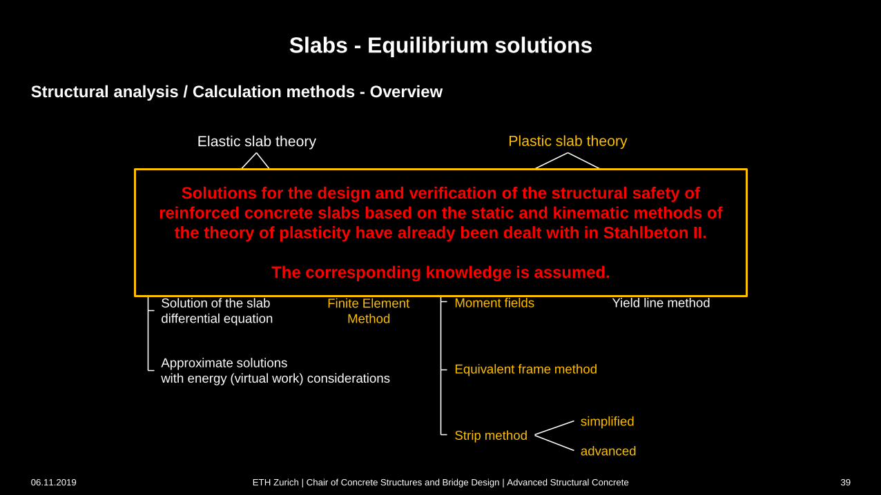
Structural analysis / Calculation methods - Overview
Slabs - Equilibrium solutions
Elastic slab theory Plastic slab theory
Solution of the slab
differential equation
Finite Element
Method
Approximate solutions
with energy (virtual work) considerations
Static method of
the theory of plasticity
Kinematic method of
the theory of plasticity
Moment fields
Equivalent frame method
Strip method
Yield line method
simplified
advanced
06.11.2019 ETH Zurich | Chair of Concrete Structures and Bridge Design | Advanced Structural Concrete 39
Solutions for the design and verification of the structural safety of
reinforced concrete slabs based on the static and kinematic methods of
the theory of plasticity have already been dealt with in Stahlbeton II.
The corresponding knowledge is assumed.
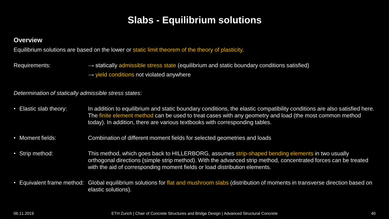
Slabs - Equilibrium solutions
Overview
Equilibrium solutions are based on the lower or static limit theorem of the theory of plasticity.
Requirements: → statically admissible stress state (equilibrium and static boundary conditions satisfied)
→ yield conditions not violated anywhere
Determination of statically admissible stress states:
• Elastic slab theory: In addition to equilibrium and static boundary conditions, the elastic compatibility conditions are also satisfied here.
The finite element method can be used to treat cases with any geometry and load (the most common method
today). In addition, there are various textbooks with corresponding tables.
• Moment fields: Combination of different moment fields for selected geometries and loads
• Strip method: This method, which goes back to HILLERBORG, assumes strip-shaped bending elements in two usually
orthogonal directions (simple strip method). With the advanced strip method, concentrated forces can be treated
with the aid of corresponding moment fields or load distribution elements.
• Equivalent frame method: Global equilibrium solutions for flat and mushroom slabs (distribution of moments in transverse direction based on
elastic solutions).
06.11.2019 ETH Zurich | Chair of Concrete Structures and Bridge Design | Advanced Structural Concrete 40
Slabs - Equilibrium solutions
Overview
Equilibrium solutions are particularly suitable for the design of slabs. If a slab is dimensioned according to these methods and
if its deformation capacity is sufficient, its load capacity will in no case be less than the corresponding load.
The static method of the theory of plasticity ensures sufficient bending resistance. However, the influence of shear forces is
not taken into account and must be investigated separately.
If a compatible failure mechanism is found for an equilibrium solution (see chapter yield line method), it corresponds to a
complete solution according to the theory of plasticity. This results in the (theoretically) exact ultimate load.
06.11.2019 ETH Zurich | Chair of Concrete Structures and Bridge Design | Advanced Structural Concrete 41
Slabs - Equilibrium solutions
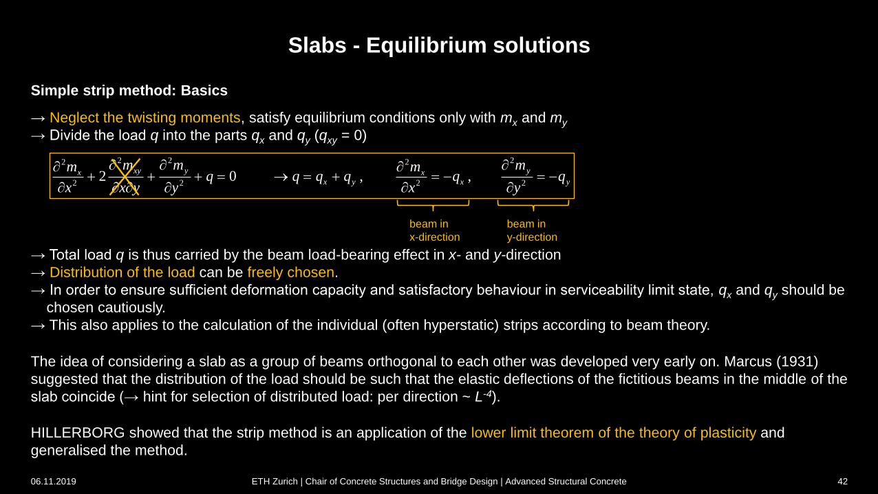
Simple strip method: Basics
2 2 22 2
2 2 2 22 0 , ,
xy y yx xx y x y
m m mm mq q q q q q
x x y y x y
beam in
x-direction
beam in
y-direction
→ Neglect the twisting moments, satisfy equilibrium conditions only with mx and my
→ Divide the load q into the parts qx and qy (qxy = 0)
→ Total load q is thus carried by the beam load-bearing effect in x- and y-direction
→ Distribution of the load can be freely chosen.
→ In order to ensure sufficient deformation capacity and satisfactory behaviour in serviceability limit state, qx and qy should be
chosen cautiously.
→ This also applies to the calculation of the individual (often hyperstatic) strips according to beam theory.
The idea of considering a slab as a group of beams orthogonal to each other was developed very early on. Marcus (1931)
suggested that the distribution of the load should be such that the elastic deflections of the fictitious beams in the middle of the
slab coincide (→ hint for selection of distributed load: per direction ~ L-4).
HILLERBORG showed that the strip method is an application of the lower limit theorem of the theory of plasticity and
generalised the method.
06.11.2019 ETH Zurich | Chair of Concrete Structures and Bridge Design | Advanced Structural Concrete 42
Slabs - Additions
Advanced strip method: Load distribution elements
Load distribution elements are used to treat supports and concentrated loads with the strip method. These convert a point
load into a uniformly distributed load or vice versa. They thus correspond to the solutions for point-supported slabs (in the
middle) under uniform loads.
Supports: The load distribution elements are regarded as area bearings with uniform compression, which are loaded by
indirectly supported strips or (usually) hidden beams. The bending resistances resulting from the beams are increased in
order to account for the bending resistances required for load transfer in the column area (= load distribution element).
Individual loads: The individual loads are applied to the slab as uniformly distributed surface loads, which are transferred to
the supports by strips or (usually) hidden beams. The resulting bending resistances of the strips are superimposed with the
bending resistances required to convert the point load into an evenly distributed area load (= load distribution element).
06.11.2019 ETH Zurich | Chair of Concrete Structures and Bridge Design | Advanced Structural Concrete 43
Slabs - Additions
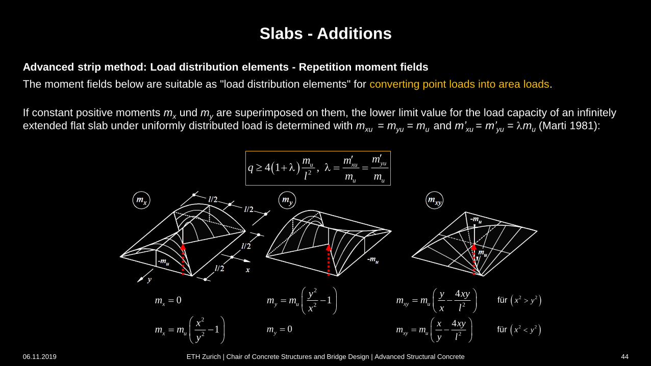
Advanced strip method: Load distribution elements - Repetition moment fields
The moment fields below are suitable as "load distribution elements" for converting point loads into area loads.
If constant positive moments mx und my are superimposed on them, the lower limit value for the load capacity of an infinitely
extended flat slab under uniformly distributed load is determined with mxu = myu = mu and m’xu = m’yu = lmu (Marti 1981):
24 1 ,
yuu xu
u u
mm mq
l m m
l l
0xm 2
21y u
ym m
x
2
4xy u
y xym m
x l
0ym 2
21x u
xm m
y
2
4xy u
x xym m
y l
2 2für yx
2 2für yx
06.11.2019 ETH Zurich | Chair of Concrete Structures and Bridge Design | Advanced Structural Concrete 44
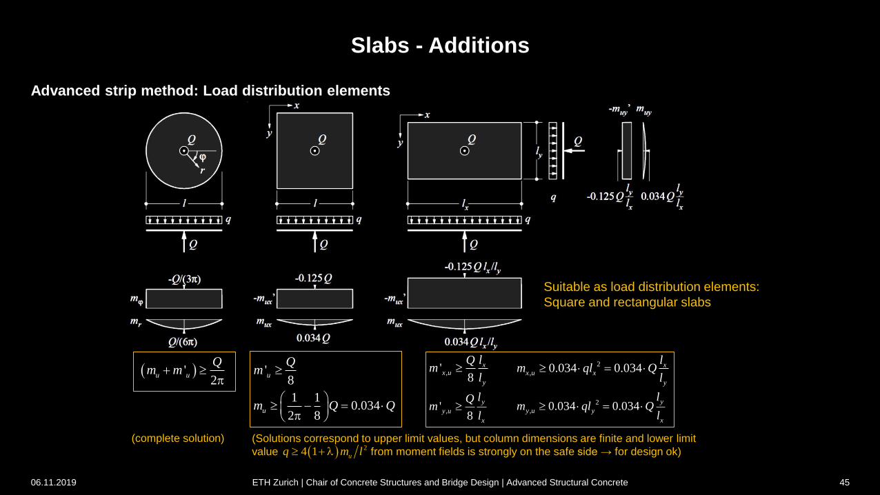
Slabs - Additions
Advanced strip method: Load distribution elements
(complete solution)
Suitable as load distribution elements:
Square and rectangular slabs
'2
u u
Qm m
p'
8u
Qm
1 10.034
2 8um Q Q
p
,'8
xx u
y
lQm
l
,'8
y
y u
x
lQm
l
2
, 0.034 0.034 xx u x
y
lm ql Q
l
2
, 0.034 0.034y
y u y
x
lm ql Q
l
(Solutions correspond to upper limit values, but column dimensions are finite and lower limit
value from moment fields is strongly on the safe side → for design ok) 24 1 uq m l l
06.11.2019 ETH Zurich | Chair of Concrete Structures and Bridge Design | Advanced Structural Concrete 45
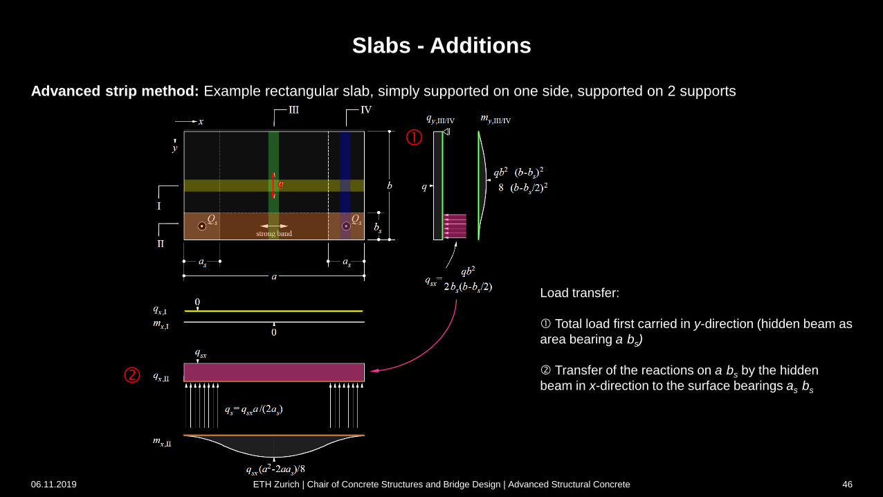
Slabs - Additions
06.11.2019 46
q
Load transfer:
Total load first carried in y-direction (hidden beam as
area bearing a·bs)
Transfer of the reactions on a·bs by the hidden
beam in x-direction to the surface bearings as·bs
Advanced strip method: Example rectangular slab, simply supported on one side, supported on 2 supports
ETH Zurich | Chair of Concrete Structures and Bridge Design | Advanced Structural Concrete
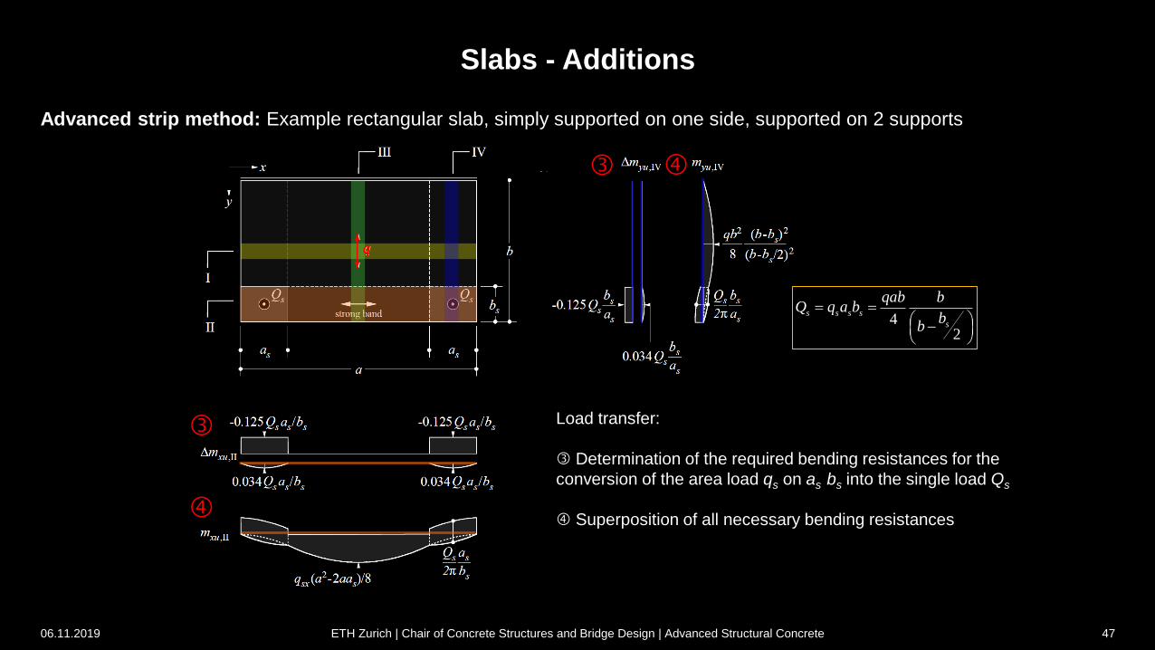
Slabs - Additions
q
Load transfer:
Determination of the required bending resistances for the
conversion of the area load qs on as·bs into the single load Qs
Superposition of all necessary bending resistances
42
s s s s
s
qab bQ q a b
bb
06.11.2019 ETH Zurich | Chair of Concrete Structures and Bridge Design | Advanced Structural Concrete 47
Advanced strip method: Example rectangular slab, simply supported on one side, supported on 2 supports
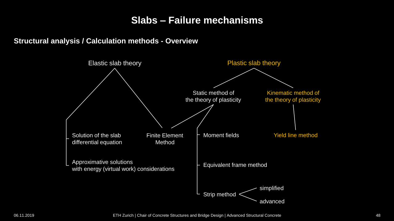
Structural analysis / Calculation methods - Overview
Slabs – Failure mechanisms
Elastic slab theory Plastic slab theory
Solution of the slab
differential equation
Finite Element
Method
Approximative solutions
with energy (virtual work) considerations
Static method of
the theory of plasticity
Kinematic method of
the theory of plasticity
Moment fields
Equivalent frame method
Strip method
Yield line method
simplified
advanced
06.11.2019 ETH Zurich | Chair of Concrete Structures and Bridge Design | Advanced Structural Concrete 48
3 Slabs
06.11.2019 ETH Zurich | Chair of Concrete Structures and Bridge Design | Advanced Structural Concrete 49
In-depth study and additions to Stahlbeton II
(Chapter 7.3)
3.4 Failure mechanisms
Slabs - Additions
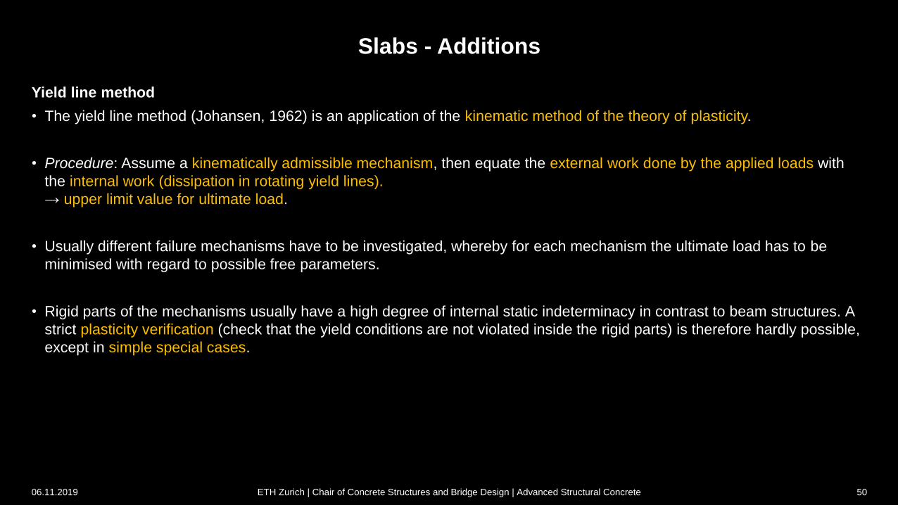
Yield line method
• The yield line method (Johansen, 1962) is an application of the kinematic method of the theory of plasticity.
• Procedure: Assume a kinematically admissible mechanism, then equate the external work done by the applied loads with
the internal work (dissipation in rotating yield lines).
→ upper limit value for ultimate load.
• Usually different failure mechanisms have to be investigated, whereby for each mechanism the ultimate load has to be
minimised with regard to possible free parameters.
• Rigid parts of the mechanisms usually have a high degree of internal static indeterminacy in contrast to beam structures. A
strict plasticity verification (check that the yield conditions are not violated inside the rigid parts) is therefore hardly possible,
except in simple special cases.
06.11.2019 ETH Zurich | Chair of Concrete Structures and Bridge Design | Advanced Structural Concrete 50
Slabs - Additions
Yield line method
• In comparison with solutions based on the elastic slab theory or equilibrium solutions, the yield line method is quite easy to
apply, especially in the verification of existing structures → The kinematic method of the theory of plasticity has become
much more widespread for slabs than for beams and membrane elements (very widespread especially in Scandinavia, also
for design).
• The "equilibrium method" (Ingerslev, 1923) can be used to circumvent the analytical minimisation process, which is often
complex, when using the yield line method. Here equilibrium is formulated at the individual, rigid slab parts of a mechanism,
whereby so-called "nodal forces" are to be considered. However, the method is only valid to a limited extent (partly
disproven recently), and the minimisation process can be carried out without any problems using numerical methods today.
It is therefore not dealt with in this course.
06.11.2019 ETH Zurich | Chair of Concrete Structures and Bridge Design | Advanced Structural Concrete 51
Slabs - Additions
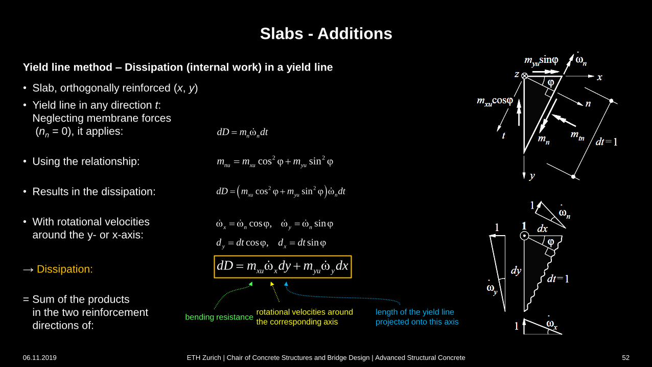
Yield line method – Dissipation (internal work) in a yield line
• Slab, orthogonally reinforced (x, y)
• Yield line in any direction t:
Neglecting membrane forces
(nn = 0), it applies:
• Using the relationship:
• Results in the dissipation:
• With rotational velocities
around the y- or x-axis:
→ Dissipation:
= Sum of the products
in the two reinforcement
directions of:
n ndD m dt
2 2cos sinnu xu yum m m j j
2 2cos sinxu yu ndD m m dt j j
cos , sinx n y n j j
cos , siny xd dt d dt j j
xu x yu ydD m dy m dx
bending resistancerotational velocities around
the corresponding axis
length of the yield line
projected onto this axis
06.11.2019 ETH Zurich | Chair of Concrete Structures and Bridge Design | Advanced Structural Concrete 52
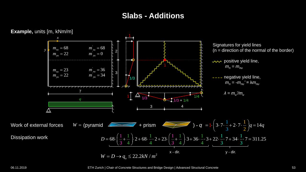
Slabs - Additions
Example, units [m, kNm/m]
3
2
Signatures for yield lines
(n = direction of the normal of the border)
positive yield line,
mn = mnu
negative yield line,
mn = -mnu’ = λmnu
λ = mu’/mu7
q
68xum
22yum ' 0yum
' 68xum
23xum
22yum ' 34yum
' 36xum
x
y
1
1/3
1/31 1/4
Work of external forces (pyramid + prism ) - q
Dissipation work
3 7 2 7 41 11
3
1
2q q
1 1 1 1
4 4 468 2 68 2 23 3 36 3 22
1 1
3 3 4
17 34 7 31 2
1
3. 5
31D
W
222.2 /uW D q kN m
3 4
06.11.2019 ETH Zurich | Chair of Concrete Structures and Bridge Design | Advanced Structural Concrete 53
1
1/3 + 1/4
x - dir. y - dir.
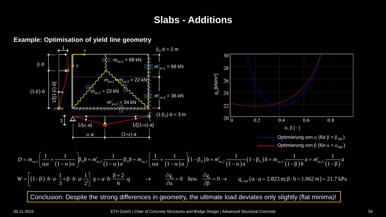
Slabs - Additions
06.11.2019 ETH Zurich | Chair of Concrete Structures and Bridge Design | Advanced Structural Concrete 54
Example: Optimisation of yield line geometry
,1 0 ,1 0 ,2 0 ,2 0 ,2 ,2
1 1 1 1 1 1 1 11 1
1 1 1 1 1 1xu xu xu xu yu yuD m b m b m b m b m a m a
a a a a a b
1
1/[
(1-
)·b
]
1/(·a)1
1/[(1-)·a]
·a (1-)·a
mxu,1 = 68 kN
mxu,2 = 23 kN
myu,1 = myu,2 = 22 kN
m’yu,2 = 34 kN
(1-)·b
·b
,
1 1 21 0 . 0 2.823 m; b 1.062 21.7 kPa
3 2 6
u uu opt
q qW b a b a q a b q bzw q a m
,
qu[k
N/m
2]
Conclusion: Despite the strong differences in geometry, the ultimate load deviates only slightly (flat minima)!
x
y
Optimierung von (für = opt )
Optimierung von (für = opt )
m’xu,1 = 68 kN
m’xu,2 = 36 kN
(1-0)·b = 3 m
0·b = 2 m
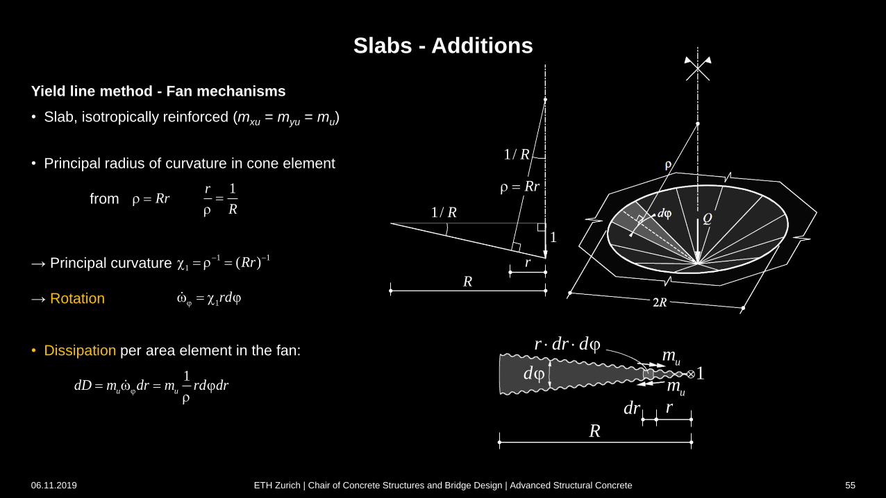
Slabs - Additions
Yield line method - Fan mechanisms
• Slab, isotropically reinforced (mxu = myu = mu)
• Principal radius of curvature in cone element
from
→ Principal curvature
→ Rotation
• Dissipation per area element in the fan:
1/ R
Rr
1
1/ R
r
R
Rr 1r
R
1 1
1 ( )Rr
1rdj j
1u udD m dr m rd drj j
06.11.2019 ETH Zurich | Chair of Concrete Structures and Bridge Design | Advanced Structural Concrete 55
um1
r
R
drum
r dr d j
dj
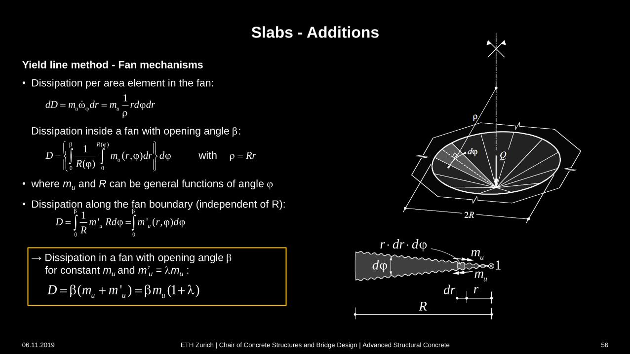
Slabs - Additions
Yield line method - Fan mechanisms
• Dissipation per area element in the fan:
Dissipation inside a fan with opening angle :
with
• where mu and R can be general functions of angle j
• Dissipation along the fan boundary (independent of R):
um1
r
R
drum
r dr d j
dj
1u udD m dr m rd drj j
( )
0 0
1( , )
( )
R
uD m r dr dR
j j j
j Rr
0 0
1' ' ( , )u uD m Rd m r d
R
j j j
06.11.2019 ETH Zurich | Chair of Concrete Structures and Bridge Design | Advanced Structural Concrete 56
( ' ) (1 )u u uD m m m l
→ Dissipation in a fan with opening angle
for constant mu and m’u = lmu :
Slabs - Additions
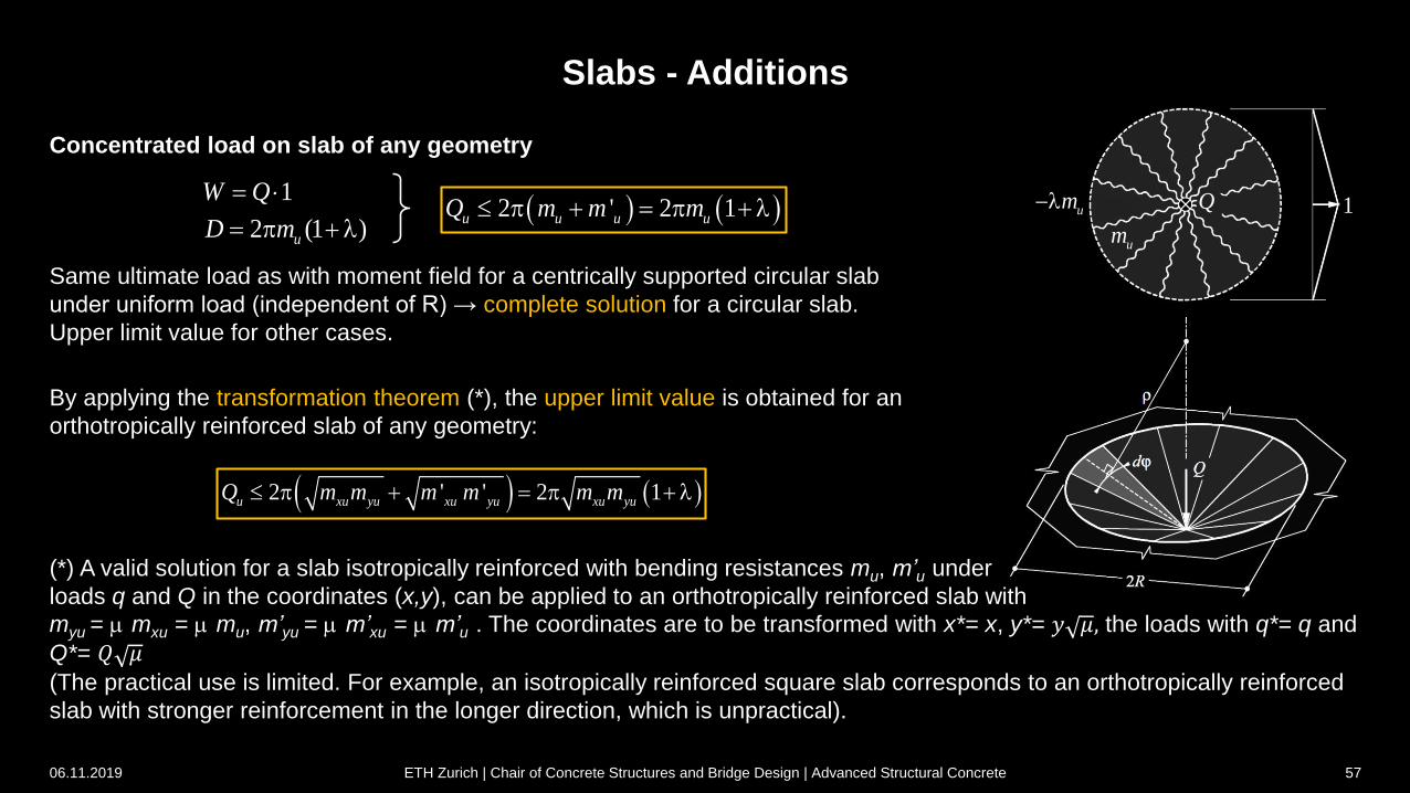
(*) A valid solution for a slab isotropically reinforced with bending resistances mu, m’u under
loads q and Q in the coordinates (x,y), can be applied to an orthotropically reinforced slab with
myu = ·mxu = ·mu, m’yu = ·m’xu = ·m’u . The coordinates are to be transformed with x*= x, y*= 𝑦 𝜇, the loads with q*= q and
Q*= 𝑄 𝜇(The practical use is limited. For example, an isotropically reinforced square slab corresponds to an orthotropically reinforced
slab with stronger reinforcement in the longer direction, which is unpractical).
1W Q
2 (1 )uD m p l
Concentrated load on slab of any geometry
uml
um
Q 1 2 ' 2 1u u u uQ m m m p p l
Same ultimate load as with moment field for a centrically supported circular slab
under uniform load (independent of R) → complete solution for a circular slab.
Upper limit value for other cases.
By applying the transformation theorem (*), the upper limit value is obtained for an
orthotropically reinforced slab of any geometry:
2 ' ' 2 1u xu yu xu yu xu yuQ m m m m m m p p l
06.11.2019 ETH Zurich | Chair of Concrete Structures and Bridge Design | Advanced Structural Concrete 57