Embed Size (px)
Citation preview
HTC Europe 2011, Bonn, Nov.8th 2011
Durability Analyses of Power Train Components
considering real Life- and Production Influences
Name: Axel Werkhausen
Date: 11/08/11

Date: 17.10.2011 Author: Unger/Werkhausen 2
Overview
1. Introduction
2. Regarding Casting Processes in Fatigue Analyses
3. Regarding Hardening Stresses in Fatigue Analyses
4. Advanced Fatigue Assessment of Welds
5. Fatigue Optimization considering Dynamics
6. Conclusions
Date: 17.10.2011 Author: Unger/Werkhausen
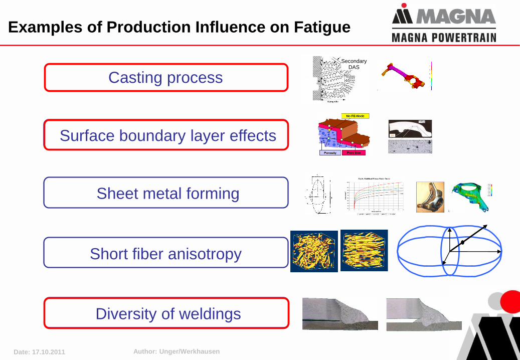
Examples of Production Influence on Fatigue
Casting process
Sheet metal forming
Short fiber anisotropy
Surface boundary layer effects
Diversity of weldings
Secondary DAS
Date: 17.10.2011 Author: Unger/Werkhausen 4
Overview
1. Introduction
2. Regarding Casting Processes in Fatigue Analyses
3. Regarding Hardening Stresses in Fatigue Analyses
4. Advanced Fatigue Assessment of Welds
5. Fatigue Optimization considering Dynamics
6. Conclusions
Date: 17.10.2011 Author: Unger/Werkhausen
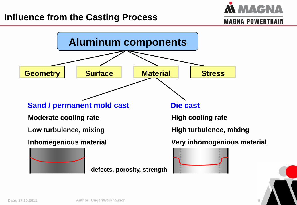
Aluminum components
Influence from the Casting Process
SurfaceGeometry Stress
Sand / permanent mold cast
Moderate cooling rate
Low turbulence, mixing
Inhomegenious material
defects, porosity, strength
Die cast
High cooling rate
High turbulence, mixing
Very inhomogenious material
Material
5
Date: 17.10.2011 Author: Unger/Werkhausen
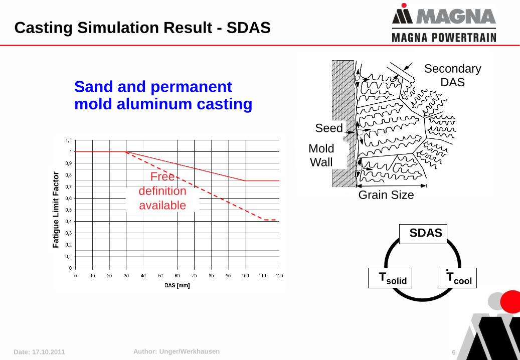
Seed
Mold Wall
Secondary DAS
Grain Size
Sand and permanent mold aluminum casting
SDAS
Tsolid Tcool
.
Fati
gu
e L
imit
Fa
cto
r
Free
definition
available
Casting Simulation Result - SDAS
6
Date: 17.10.2011 Author: Unger/Werkhausen
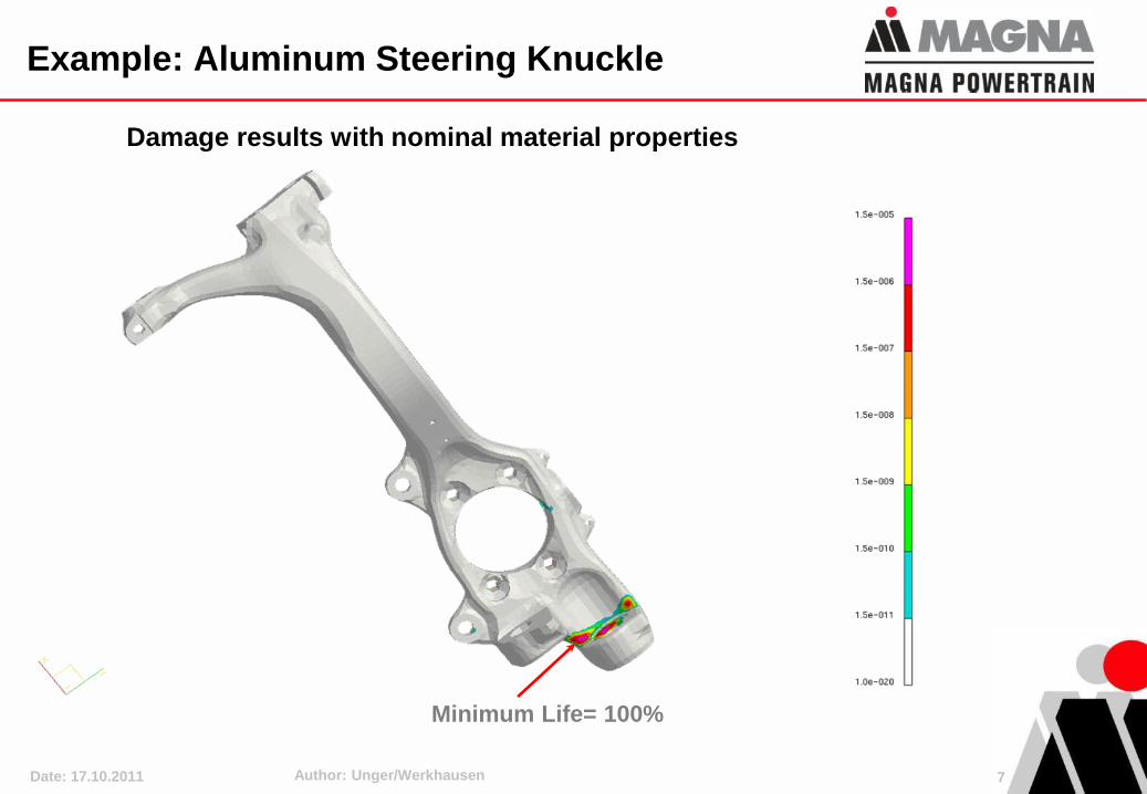
Damage results with nominal material properties
Minimum Life= 100%
Example: Aluminum Steering Knuckle
7
Date: 17.10.2011 Author: Unger/Werkhausen
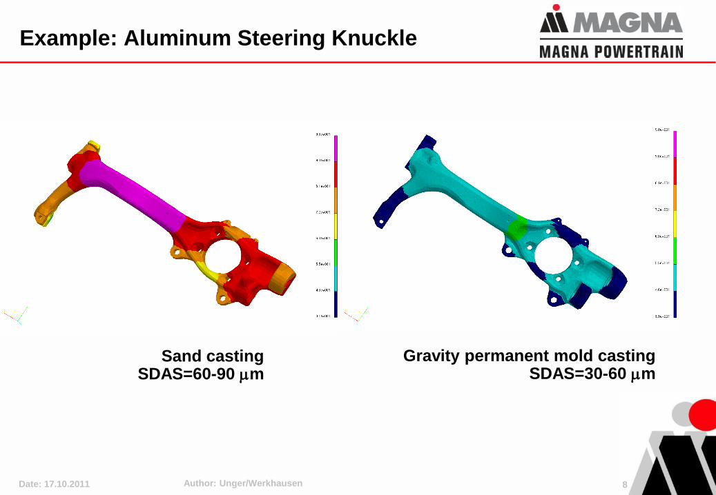
Sand casting SDAS=60-90 m
Gravity permanent mold castingSDAS=30-60 m
Example: Aluminum Steering Knuckle
8
Date: 17.10.2011 Author: Unger/Werkhausen
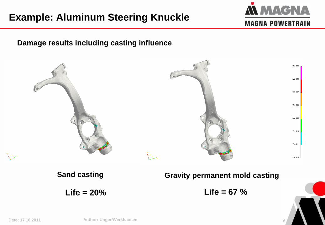
Damage results including casting influence
Sand casting
Life = 20%
Gravity permanent mold casting
Life = 67 %
Example: Aluminum Steering Knuckle
9
Date: 17.10.2011 Author: Unger/Werkhausen
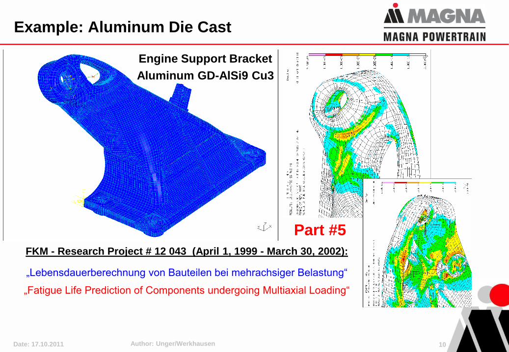
Engine Support Bracket
Aluminum GD-AlSi9 Cu3
Part #5
FKM - Research Project # 12 043 (April 1, 1999 - March 30, 2002):
„Lebensdauerberechnung von Bauteilen bei mehrachsiger Belastung“
„Fatigue Life Prediction of Components undergoing Multiaxial Loading“
Example: Aluminum Die Cast
10
Date: 17.10.2011 Author: Unger/Werkhausen
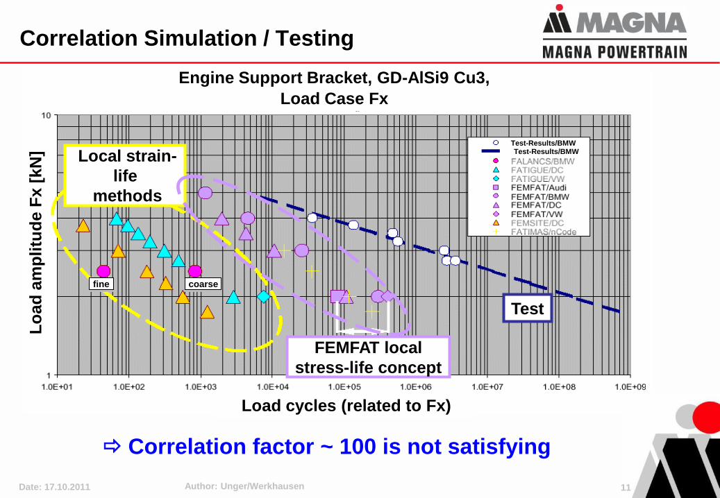
Engine Support Bracket, GD-AlSi9 Cu3,
Load Case Fx
Lo
ad
am
pli
tud
e F
x [
kN
]
Local strain-
life
methods
fine coarse
FEMFAT local
stress-life concept
Test-Results/BMWTest-Results/BMW
Load cycles (related to Fx)
Test
Correlation factor ~ 100 is not satisfying
Correlation Simulation / Testing
11
Date: 17.10.2011 Author: Unger/Werkhausen
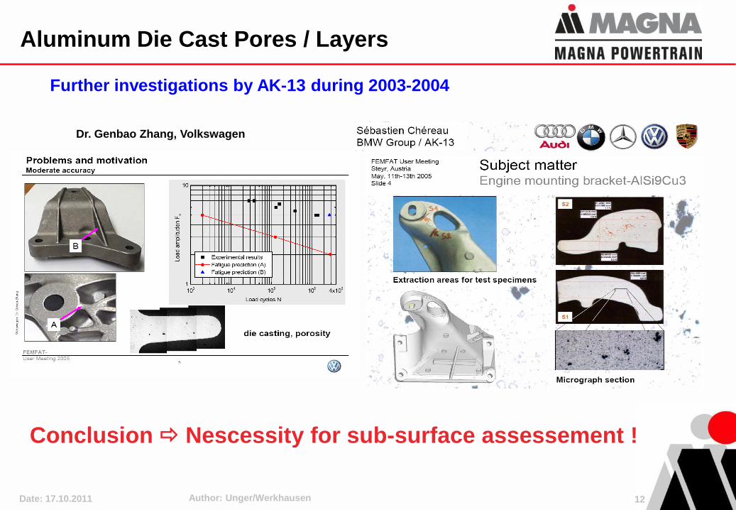
Further investigations by AK-13 during 2003-2004
Conclusion Nescessity for sub-surface assessement !
Dr. Genbao Zhang, Volkswagen
Aluminum Die Cast Pores / Layers
12
Date: 17.10.2011 Author: Unger/Werkhausen
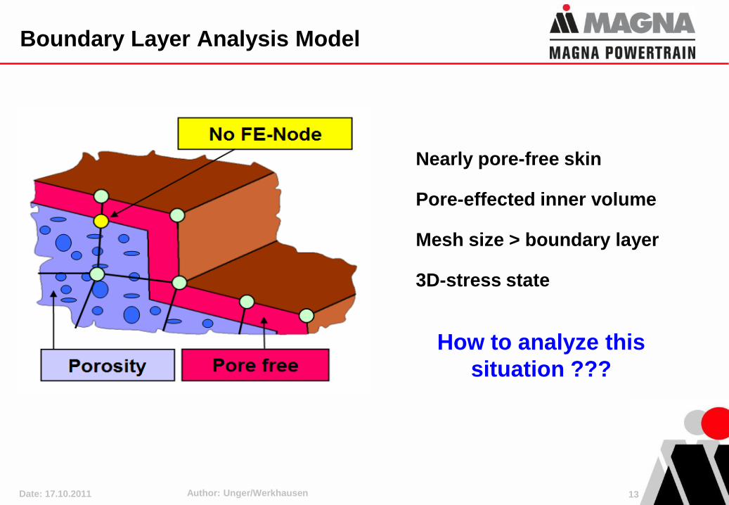
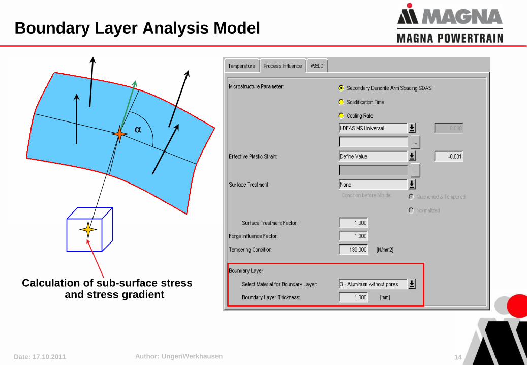
Nearly pore-free skin
Pore-effected inner volume
Mesh size > boundary layer
3D-stress state
How to analyze this
situation ???
Boundary Layer Analysis Model
13
Date: 17.10.2011 Author: Unger/Werkhausen
Boundary Layer Analysis Model
Calculation of sub-surface stress and stress gradient
14
Date: 17.10.2011 Author: Unger/Werkhausen
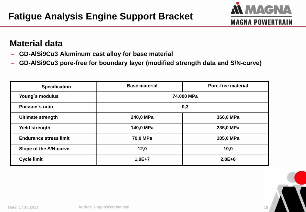
Fatigue Analysis Engine Support Bracket
Material data– GD-AlSi9Cu3 Aluminum cast alloy for base material
– GD-AlSi9Cu3 pore-free for boundary layer (modified strength data and S/N-curve)
Specification Base material Pore-free material
Young´s modulus 74.000 MPa
Poisson´s ratio 0,3
Ultimate strength 240,0 MPa 366,6 MPa
Yield strength 140,0 MPa 235,0 MPa
Endurance stress limit 70,0 MPa 105,0 MPa
Slope of the S/N-curve 12,0 10,0
Cycle limit 1,0E+7 2,0E+6
15
Date: 17.10.2011 Author: Unger/Werkhausen
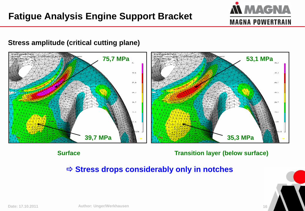
Fatigue Analysis Engine Support Bracket
Stress amplitude (critical cutting plane)
75,7 MPa
Surface
39,7 MPa
Stress drops considerably only in notches
Transition layer (below surface)
35,3 MPa
53,1 MPa
16
Date: 17.10.2011 Author: Unger/Werkhausen
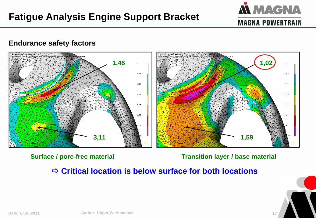
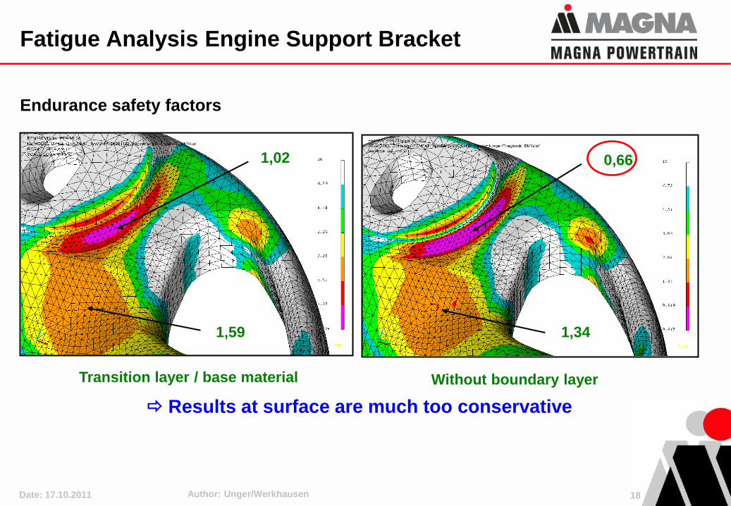
Fatigue Analysis Engine Support Bracket
Endurance safety factors
Surface / pore-free material
3,11
1,46
Transition layer / base material
1,59
1,02
Critical location is below surface for both locations
17
Date: 17.10.2011 Author: Unger/Werkhausen
Fatigue Analysis Engine Support Bracket
Endurance safety factors
Transition layer / base material
1,59
1,02
1,34
0,66
Without boundary layer
Results at surface are much too conservative
18
Date: 17.10.2011 Author: Unger/Werkhausen 19
Overview
1. Introduction
2. Regarding Casting Processes in Fatigue Analyses
3. Regarding Hardening Stresses in Fatigue Analyses
4. Advanced Fatigue Assessment of Welds
5. Fatigue Optimization considering Dynamics
6. Conclusions
Date: 17.10.2011 Author: Unger/Werkhausen 20
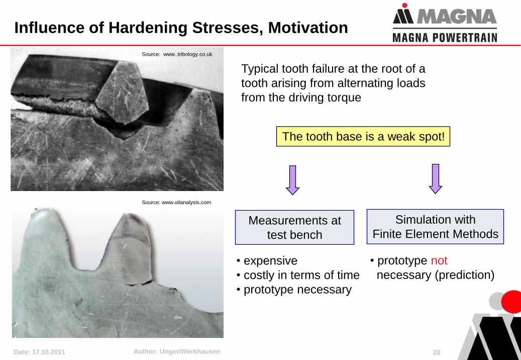
Influence of Hardening Stresses, Motivation
Source: www..tribology.co.uk
Typical tooth failure at the root of a
tooth arising from alternating loads
from the driving torque
Source: www.oilanalysis.com
The tooth base is a weak spot!
Measurements at
test bench
Simulation with
Finite Element Methods
• expensive
• costly in terms of time
• prototype necessary
• prototype not
necessary (prediction)
Date: 17.10.2011 Author: Unger/Werkhausen 21
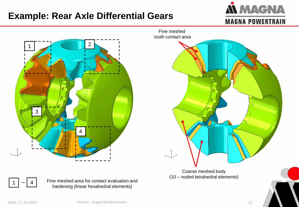
Example: Rear Axle Differential Gears
Fine meshed area for contact evaluation and
hardening (linear hexahedral elements)
Coarse meshed body
(10 – noded tetrahedral elements)
1
3
4
21
4
Fine meshed
tooth contact area
Date: 17.10.2011 Author: Unger/Werkhausen 22
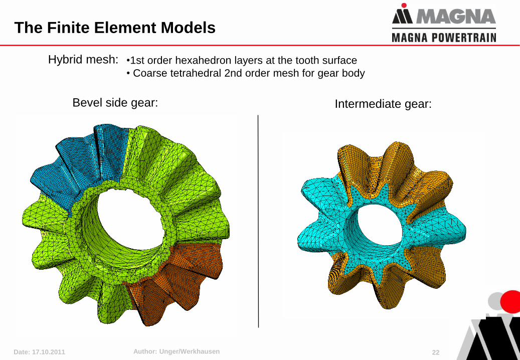
The Finite Element Models
•1st order hexahedron layers at the tooth surface
• Coarse tetrahedral 2nd order mesh for gear body
Bevel side gear: Intermediate gear:
Hybrid mesh:
Date: 17.10.2011 Author: Unger/Werkhausen 23
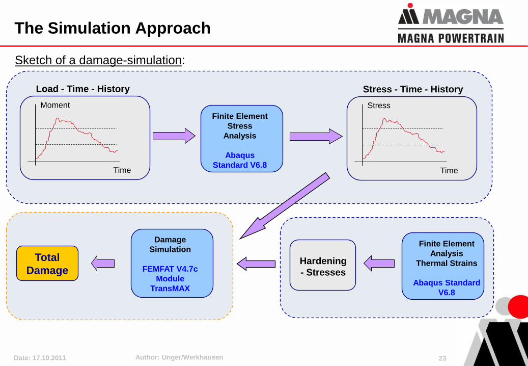
The Simulation Approach
Sketch of a damage-simulation:
Time
Moment
Finite Element
Stress
Analysis
Abaqus
Standard V6.8
Load - Time - History
Time
Stress
Stress - Time - History
Damage
Simulation
FEMFAT V4.7c
Module
TransMAX
Total
DamageHardening
- Stresses
Finite Element
Analysis
Thermal Strains
Abaqus Standard
V6.8
Date: 17.10.2011 Author: Unger/Werkhausen 24
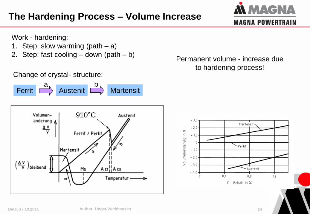
The Hardening Process – Volume Increase
Work - hardening:
1. Step: slow warming (path – a)
2. Step: fast cooling – down (path – b)
910°C
Change of crystal- structure:
Ferrit Austenit Martensita b
Permanent volume - increase due
to hardening process!
Date: 17.10.2011 Author: Unger/Werkhausen 25
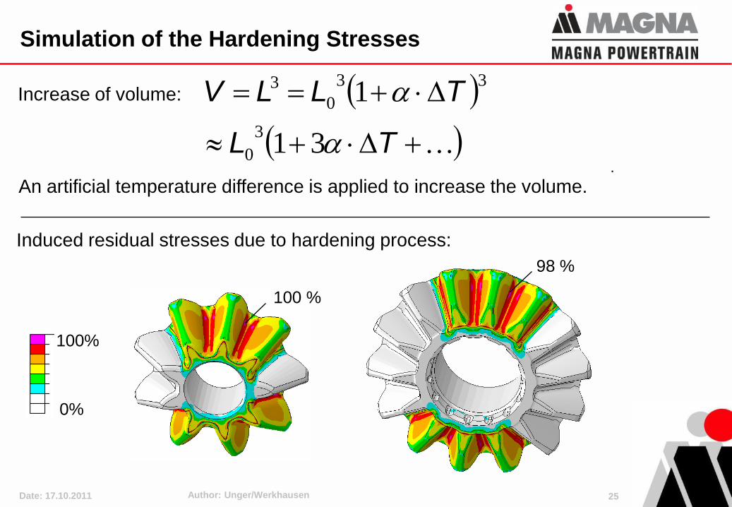
Simulation of the Hardening Stresses
TL
TLLV
31
1
3
0
33
0
3Increase of volume:
An artificial temperature difference is applied to increase the volume.
100 %
98 %
.
Induced residual stresses due to hardening process:
0%
100%
Date: 17.10.2011 Author: Unger/Werkhausen 26
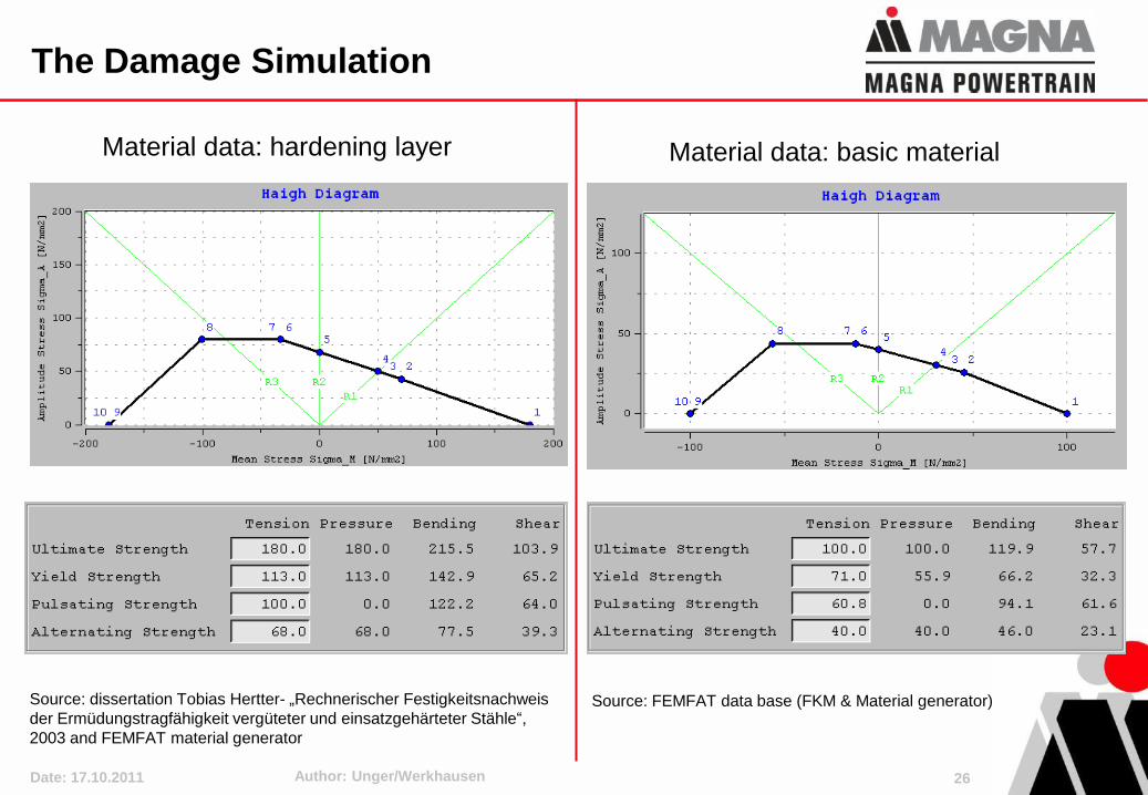
The Damage Simulation
Material data: hardening layer Material data: basic material
Source: dissertation Tobias Hertter- „Rechnerischer Festigkeitsnachweis
der Ermüdungstragfähigkeit vergüteter und einsatzgehärteter Stähle“,
2003 and FEMFAT material generator
Source: FEMFAT data base (FKM & Material generator)
Date: 17.10.2011 Author: Unger/Werkhausen 27
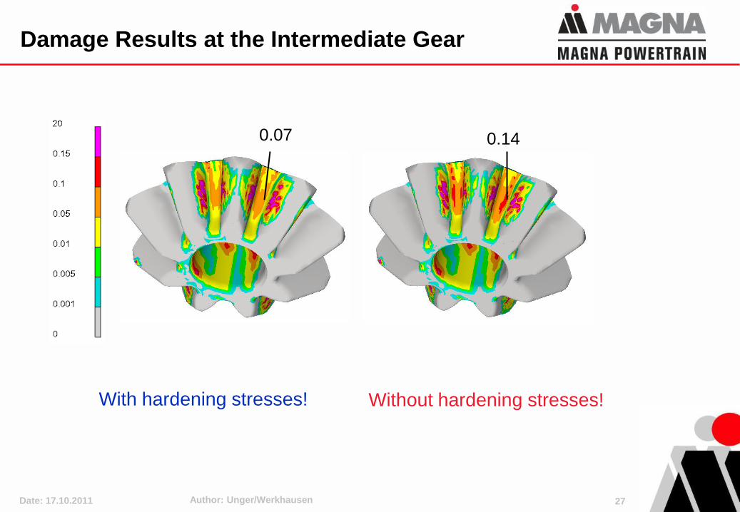
Damage Results at the Intermediate Gear
0.07 0.14
With hardening stresses! Without hardening stresses!
Date: 17.10.2011 Author: Unger/Werkhausen 28
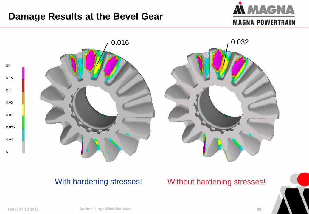
Damage Results at the Bevel Gear
0.016 0.032
With hardening stresses! Without hardening stresses!
28
Date: 17.10.2011 Author: Unger/Werkhausen 29
Overview
1. Introduction
2. Regarding Casting Processes in Fatigue Analyses
3. Regarding Hardening Stresses in Fatigue Analyses
4. Advanced Fatigue Assessment of Welds
5. Fatigue Optimization considering Dynamics
6. Conclusions
Date: 17.10.2011 Author: Unger/Werkhausen
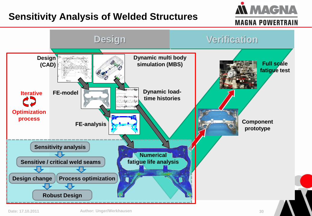
Component
prototype
Full scale
fatigue test
Optimization
process
Iterative
Sensitivity analysis
Sensitive / critical weld seams
Design change Process optimization
Robust Design
Design Verification
Dynamic multi body
simulation (MBS)
Dynamic load-
time histories
FE-analysis
FE-model
Numerical
fatigue life analysis
Design
(CAD)
Sensitivity Analysis of Welded Structures
30
Date: 17.10.2011 Author: Unger/Werkhausen
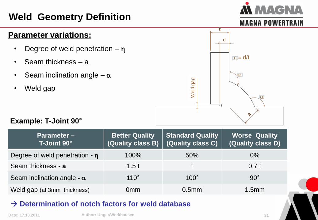
Parameter –
T-Joint 90°
Better Quality
(Quality class B)
Standard Quality
(Quality class C)
Worse Quality
(Quality class D)
Degree of weld penetration - h 100% 50% 0%
Seam thickness - a 1.5 t t 0.7 t
Seam inclination angle - 110° 100° 90°
Weld gap (at 3mm thickness) 0mm 0.5mm 1.5mm
Parameter variations:
• Degree of weld penetration – h
• Seam thickness – a
• Seam inclination angle –
• Weld gap
h d/t
Weld
ga
p
Example: T-Joint 90°
Determination of notch factors for weld database
Weld Geometry Definition
31
Date: 17.10.2011 Author: Unger/Werkhausen
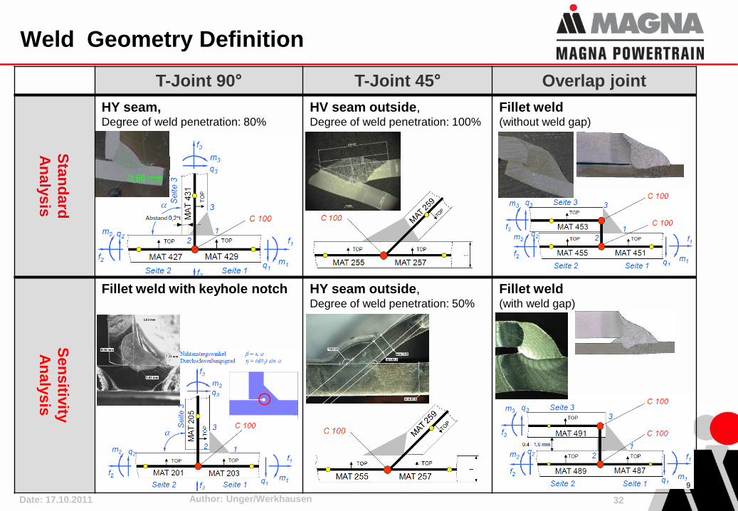
T-Joint 90° T-Joint 45° Overlap joint
Sta
nd
ard
An
aly
sis
HY seam, Degree of weld penetration: 80%
HV seam outside, Degree of weld penetration: 100%
Fillet weld(without weld gap)
Sen
sitiv
ity
An
aly
sis
Fillet weld with keyhole notch HY seam outside, Degree of weld penetration: 50%
Fillet weld(with weld gap)
9
Weld Geometry Definition
32
Date: 17.10.2011 Author: Unger/Werkhausen
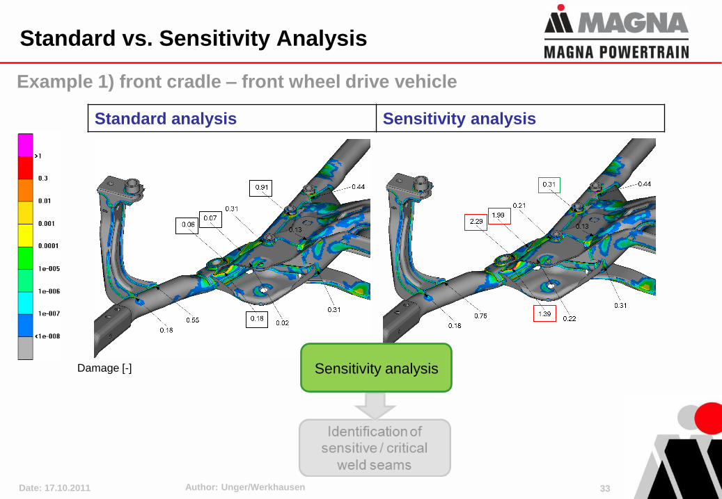
Damage [-]
Standard analysis Sensitivity analysis
Sensitivity analysis
1
1
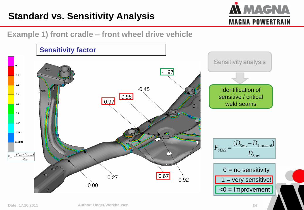
Example 1) front cradle – front wheel drive vehicle
Standard vs. Sensitivity Analysis
33
Date: 17.10.2011 Author: Unger/Werkhausen
Sens
dardSSensSENS
D
DDF
)( tan
Sensitivity factor
Identification of
sensitive / critical
weld seams
Sens
dardSSensSENS
D
DDF
)( tan
0 = no sensitivity
1 = very sensitive!
<0 = Improvement
Example 1) front cradle – front wheel drive vehicle
Standard vs. Sensitivity Analysis
34
Date: 17.10.2011 Author: Unger/Werkhausen 35
Overview
1. Introduction
2. Regarding Casting Processes in Fatigue Analyses
3. Regarding Hardening Stresses in Fatigue Analyses
4. Advanced Fatigue Assessment of Welds
5. Fatigue Optimization considering Dynamics
6. Conclusions
Date: 17.10.2011 Author: Unger/Werkhausen
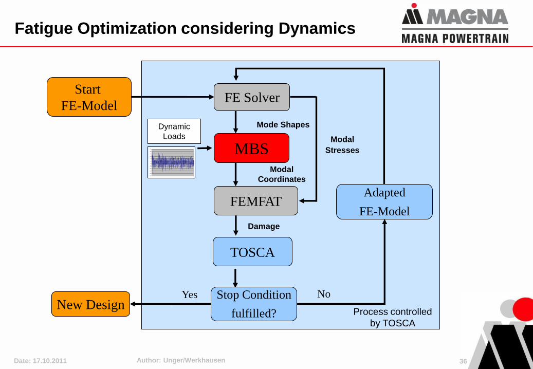
Fatigue Optimization considering Dynamics
MBS
FEMFAT
Mode Shapes
Modal
Stresses
Start
FE-ModelFE Solver
Adapted
FE-Model
NoYesNew Design
Modal
Coordinates
Damage
-30
-25
-20
-15
-10
-5
0
5
10
15
20
25
Dynamic
Loads
Process controlled
by TOSCA
TOSCA
Stop Condition
fulfilled?
36
Date: 17.10.2011 Author: Unger/Werkhausen
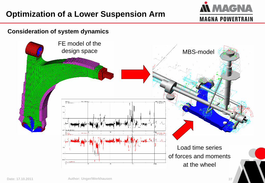
Optimization of a Lower Suspension Arm
Consideration of system dynamics
FE model of the
design space MBS-model
Load time series
of forces and moments
at the wheel
37
Date: 17.10.2011 Author: Unger/Werkhausen
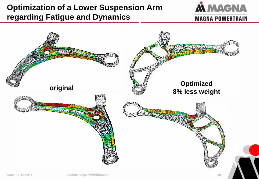
Optimization of a Lower Suspension Arm
regarding Fatigue and Dynamics
originalOptimized
8% less weight
38
Date: 17.10.2011 Author: Unger/Werkhausen
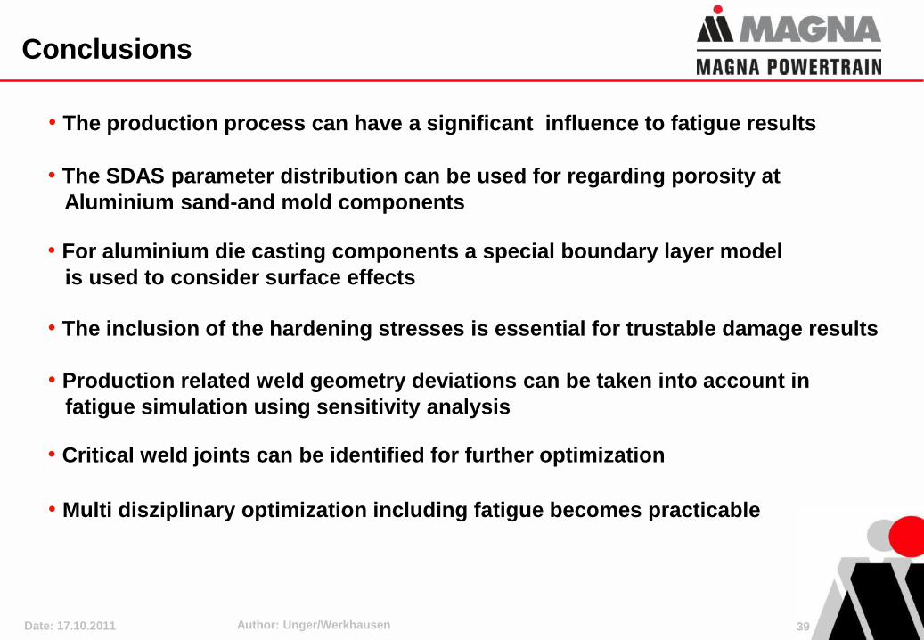
Conclusions
39
• For aluminium die casting components a special boundary layer model
is used to consider surface effects
• The SDAS parameter distribution can be used for regarding porosity at
Aluminium sand-and mold components
• The production process can have a significant influence to fatigue results
• The inclusion of the hardening stresses is essential for trustable damage results
• Production related weld geometry deviations can be taken into account in
fatigue simulation using sensitivity analysis
• Critical weld joints can be identified for further optimization
• Multi disziplinary optimization including fatigue becomes practicable
Date: 17.10.2011 Author: Unger/Werkhausen
Thank you for your Attention !
40


![Fatigue Crack Growth Under Constant and Variable Amplitude ... · crack closure effects, crack tip blunting, strain hardening and residual stresses at the crack tip [8]. In this paper,](https://img.pdfslide.us/doc/110x75/5e57a3e927dba642fd37d97c/fatigue-crack-growth-under-constant-and-variable-amplitude-crack-closure-effects.jpg)