Embed Size (px)
Citation preview

2. Rated Voltage kV 36 kV
3. Rated Primary Voltage kV 33/3
Rated Secondary Voltage
Core 1 kV 0.110/3
Core 2 kV 0.110/3
5. Impulse withstand voltage kV 170 kV
(1.2/50 micro sec.)
6. Power Frequency withstand Voltage kV 70 kV
7. BURDEN/CLASS
For metering winding
Core 1 VA/cl 100 / 0.2
Core 2 VA/cl 100 / 3p
5.7 33/0.4KV, 100KVA OUTDOOR AUXILIARY TRANSFORMERS
Sl.
No.
Description Unit Requirements
1.
2.
3.
Rated power
Type of cooling
Principal tapping
kVA
100
ONAN

4.
5.
6.
7.
8.
9.
10.
11.
12.
13.
High voltage
Low voltage
Vector symbol
Type of tap changer
Tapping range
Tapping steps
Number of windings
Insulation
Number of phases
Frequency (supply)
Impedance voltage at 75oC and normal ratio
Terminal arrangements
HV terminals
LV terminals (3-phase 4-wire)
kV
V
Hz
33
415
Dyn 11
Off circuit
5%
2.5%
2
to IEC 76
3
50
5%
Outdoor
bushings
Cable box
5.8 LV AC Distribution Panel
Vermin and dust proof, completely metal enclosed by sheet steel (11 u.s.s gauge) with necessary reinforcement,
colour grey with appropriate spray painting, free standing type, compact in size, suitable for opening at the back
by hinged door with locking device.
There shall be a 3 phase 400 A, 1 kV bus (cu) arrangement with Neutral bus being connected with the following
MCCBs and instruments:
i) Voltmeter with 6 position selector switch connected to the bus.

ii) Ammeter with selector switch
iii) kwh meter for each transformer
v) Two 400 A, 4 Pole MCCB being interlocked with each other, operative one at a time to bring the Input
Power to the Bus.
iii) 10 60 A, 3 Pole MCCB as outgoing or as required.
iv) 10 30 A, 3 Pole MCCB as outgoing or as required.
All MCCBs are provided with over load setting and short circuit tripping device.
Necessary terminal blocks and glands/openings shall be provided for the entry of suitable cables.
All equipment/instruments inside the panel shall be arranged neatly and sufficient space shall be provided for
easy approach to each equipment/instrument.
Thermostat control panel heater, bulb for inside illumination of panel shall be provided.
All other features as stated in the table of guaranteed data schedule shall be applicable also.
5.9 DC Distribution Panel, Battery set and Battery Charger (110v)
5.9.1 DC distribution panel

The Contractor shall provide fully comprehensive d. c. systems at all new sites or where otherwise required in the
schedules. The capacity of the batteries installed be adequate to meet the load-duties of the plant provided in
accordance with the requirements of this Specification plus all additional circuits shown as future on the drawings
or in the schedules.
Completely separate d. c. systems are required for the following duties:
33 kV Switchgear Tripping, protection, alarms, indication etc. 110 V
Emergency lighting (if required by the Contractors design)
Each Switchgear d. c. system shall comprise duplicate 100% chargers with two 50% Battery banks, designed to
operate for a standby period of 8 hours. Emergency lighting systems, if proposed, shall comprise a single 100%
charger and battery units.
There shall be two cu-bus, 200 A rated, 1 kV insulation
A D.C Voltmeter 0-250 V shall be connected to the bus.
Two x 100 A MCCB (2 Pole) will be the Incomings. Each of the Incoming shall have ammeter (centre zero) to
indicate the flow of current.
15 Nos. of 15A-30A MCB (two pole) will be the outgoings
An earth fault detection equipment on each bus-bar to give local indication and remote alarm of the occurrence
of an earth fault and to give discrimination between positive pole & negative pole earth faults.
All other features as stated in the table of guaranteed data shall be applicable also.

5.9.2 Sub-Station Battery
Application
Installation
Type
Operating Voltage
Continuous discharge
Capacity (at 5 hr. rate)
No of cell
Discharging voltage
Charging voltage (Float)
Charging voltage (Boast)
:
:
:
:
:
:
:
:
:
:
Supply for Remote Control, operation,
Indication, Protective and Regulation
apparatus, Emergency light etc.
Indoor (self supporting unit)
Nickel Cadmium
110 V, D.C.
10 A during 10 hour
250 Ampere hour
92
1.0-1.42 Volt per cell
1.4-1.42 Volt per cell
1.54 -1.69Volts per cell
Transparent plastic

Type of container
Mounting
Construction
Standard
:
:
:
:
Cabinet
Closed top
All equipment and materials shall be
designed, manufactured and tested in
accordance with the latest editions of
applicable IEC standard unless otherwise
specified in the specification. Other
internationally acceptable standards will
also be considered provided that
relevant values are at least similar to
those under IEC standards.
Features and Accessories:
The battery shall be Nickel Cadmium Alkaline type, negative plates shall have life equal to or greater than positive
plates.
The battery shall have built in protection against active materials shedding and grid corrosion and shall be
assembled in heat-resistant, shock-absorbing, containers. The containers and covers are connected together to
form a leak proof bond against seepage of electrolyte.
Battery Type
The batteries shall be of high performance nickel cadmium pocket plate type complying with IEC 623:1978 and
shall be designed for a life expectancy of at least 25 years under the conditions of service likely to be encountered
by the equipment detailed in this Specification. A complete set of test maintenance accessories suitably boxed,
shall be provided for each battery installation. A syringe hydrometer and durable instruction card shall be include
in each set.

Battery cases shall be of high impact translucent plastic.
The electrolyte shall be free from impurities and the potassium Hydroxide used shall comply with BS 5633: 1978.
Dilution of the alakaline electrolyte and topping up of cells shall be carried out using distilled water only.
Cells shall be permanently marked with the following information:
Manufacturer’s reference number and code
Year and month of manufacture
Voltage and nominal capacity at the 10 hour discharge rate.
Battery and DC System Voltages
The nominal d.c voltage for all battery systems installed under this contract shall be 110V for Switchgear systems.
The dc system shall prevent the boost-charging voltage appearing on the distribution equipment and substation
plant.
All d.c energized apparatus is to be adequately rated to operate over a voltage range of 80% to 110% of nominal
d.c voltage, apart from circuit breaker shunt opening releases which shall operate between 70% and 110% of
nominal d.c voltage in accordance with ICE 56.3 and IEC 694.
The battery capacity however, shall be designed to operate over a voltage range of +10% to 15% of nominal dc
voltage. All secondary cabling shall limit the maximum volt-drop to 5% at peak load, measured from battery
terminals to individual items of plant.
The rating of each battery shall be sufficient to met the total electrical loading of the system for all equipments
including an allowance for all future items requiring battery supply and make adequate provision for
manufacturing tolerances and diversity factors. The following criteria shall be adopted and the calculations shall
observe fully the requirements of Clause 43 of BS 162.

The rating of each battery shall be on the basis as specified and is subject to adjustment after award of contract
such that when charged to its rated capacity at the start of the duties, it shall be sufficient to supply the demands
with the charger disconnected for the specified period of time, and be capable of closing each CB consecutively
and then tripping all circuit breakers simultaneously at the end of this period.
At the end of all these duties the battery voltage shall not have dropped such that the voltage at the battery
terminals falls below 85% of the nominal system voltage when supplying the standing load.
In addition the voltages at the terminals of all components in the system (e.g. relays, trip and closing coils) shall
not be outside of the individual voltage limits applying to them.
All quantities used in estimating the battery capacity shall be submitted for consideration but shall not be used
for procuring materials until specifically approved by the Employer
The electrolyte capacity and general design of the batteries shall be such that inspection and maintenance,
including topping up of all electrolyte shall be at intervals of net less than twelve months.
Duties
The rating of each battery shall be determined by ten Contractor to meet the requirements of the duty cycle of
each system.
Where the capacity of a battery is described as a percentage (e.g. 50%), this percentage is deemed to refer to the
product of the total d. c. load current on the distribution switchboard and the specified discharge period. Should
the d. c. load current vary during the discharge period, a mean value may be used for calculation of battery
capacity, providing the average is suitably weighted to take account of the apparent loss of capacity which will
occur during period of a high rate of discharge.

5.9.3 Battery Charger
Rectifier type : Thyristor
Nominal output voltage : 110 D.C.
Input voltage : 415 V, 50 Hz, 3 phases.
Charging operating : Boost and floating charge,
control automatic with manual operation.
Maximum charging current : 5./0 A (D.C.)
Provision for constant current 15A-40A shall be provided
Provision for constant voltage 90 V-130 V shall be provided
Feature and Accessories:
- All interconnections, nuts and bolts shall be non-corrosive type.
- Battery charger with a voltmeter (0 to 250V D.C. scale) and dual scale ampere meter (50- 0-50 Amp.),
both flush pattern type with 4 inch (approx.) dials.
- The unit shall have setting knobs for constant charging current within the specified range and constant
voltage within the specified range.

- Necessary accessories for battery charger, such as small wiring fuses, terminals, block switches and
miscellaneous.
- Appropriate tamper proof sheet steel housing for battery charger.
- The housing shall have storage space for accessories and provision for locking.
Necessary interconnections between battery and battery and battery charger, D.C. output terminals, A.C. input
terminals and A.C. disconnect switch.
The cell terminal posts of the inter-cell and end cell connectors shall have adequate current carrying capacity and
shall be of lead alloy or lead alloy reinforced with copper inserter. The container shall be filled with sufficient
quantity of Alkaline solution complying with Internationally acceptable standards to ensure that the surface of
Alkali is leveled with the level mark.
Cells shall be equipped with necessary bolts and acid resisting nuts, shall be furnished with all the bolts.
Plates shall be hung suspended without touching the bottom of the containers. Containers shall provide sufficient
sediment space so that the plates in the cell, as well as to avoid cleaning of cells during the expected life of the
battery.
110% of the required electrolyte meeting the manufacturer’s Specification shall be supplied at the correct filling
specific gravity with each battery. The Electrolyte shall be packaged in 15 gallons or less plastic coated steel drum
or in plastic containers. After discharging off the specified rated capacity, the battery shall have the voltage
including the internal resistance drip of all inter cell and inter rack connectors not to drop below 1.10 VPC.
The battery rack shall be few step structural steel and shall be painted with 2 coats of acid resistant grey paint.
Inter rack connector terminal lugs shall be provided with each rack.
Battery shall be shipped dry with concentrated electrolyte in separate containers.

The following accessories shall be supplied with each battery set:
- Two lead plated lugs for No. 4/0 AWG copper cable.
- Two portable hydrometer syringes.
- One set of socket wrenches to fit nuts.
- Polyethylene bottle with extendable tube for topping up the battery.
- Special voltmeters to measure cell voltage.
- One gallon of anti-corrosive paint.
The following spare parts shall be supplied with each battery set:
- One positive plate
- One negative plate
- One spare container and cover
- One vent plug
- One gallon electrolyte
The battery shall be tropicalized.
All other features as stated in the table of guaranteed data schedule shall be applicable also.
DC switchboard

The distribution switchboard shall be of the cubicle type or otherwise incorporated in the cubicles for battery
chargers. Double pole miniature or moulded case circuit-breakers to BS 4752 or IEC 157 shall be fitted to the DC
switchboard as required by substation services, subject to the minimum requirement set out below.
The Contractor shall ensure that the DC schemes are fully discriminative and shall submit calculations and
performance curves to demonstrate this.
MCCBs and MCCBs shall be fitted with auxiliary contacts which shall raise alarms on the associated bus-section or
bus-coupler control panel, for the loss of supplies.
The DC switchboard shall provide individual duplicate supplies, at each voltage level for
Protection (separate supplies required where duplicate protection provided).
Control and indication
Alarm
Switchyard/switchgear.
In addition each individual transformer shall have its own DC supply for tap-changing etc.
Any additional DC supplies necessary for the specific plant design of the Contractor shall also be provided.
At least six 15A spare ways shall be provided, in addition to facilities for future circuits.
Each circuit shall be adequately labeled with its respective function.

A voltmeter shall be provided to indicate the DC system voltage on each distribution bus-bar.
5.9.4 Alarm Devices
The following shall be provided on the dc distribution switchboard:
Over voltage detection equipment of equipment on each busbar to give local indication and remote alarm when
the DC voltage rises more than 5% above the normal Automatic float voltage. A time delay shall be incorporated
to prevent operation when a battery with high open circuit voltage is switched form the boost to float condition.
Under voltage detection equipment on each bus-bar to give local indication and remote alarm when the system
voltage falls below 80% (adjustable) of the rated system voltage. A time delay shall be incorporated to prevent
initiation during temporary voltage drops caused by transient conditions including circuit-breaker closing
operations.
Earth leakage detection equipment on each bus-bar to give local indication and remote alarm of the occurrence
of an earth fault and to give discrimination between positive pole and negative pole earth faults. Test circuits
shall be incorporated to simulate positive and negative faults by operation of test pushbuttons.
Provision of “Local Indication” by lamps on the front of the switchboard and provision for “Remote Alarm” by
changeover contacts (rated at 5A for voltages between 30 and 130V AC or DC) on the devices to energizes a
group alarm relay.
5.9.5 INSPECTION AND TESTING

Inspection and testing during manufacture shall be in accordance with the General conditions of the contract and
as per this Specification.
The following list gives the minimum requirements to comply with this Specification.
5.9.6 Tests at Manufactures works
Battery – Routine Tests in accordance with IEC 623. Type test certificates shall also be supplied.
Battery Charger – Type and Routine Tests according to IEC. 146:1973 (BS 4417:1996).
DC Switchboard – Type and Routine Tests according to ICE 439:1973 (BS 5486:Part 1, 1977).
5.9.7 Site Tests
Insulation check of charger and switchboard with 500V megger between poles and to ground. (All diodes and
electronics to be short circuited during test).
Check that all transit plugs have been removed and that each cell has been filled with the electrolyte to the
correct level.
General inspection and testing of battery equipment to manufacturers instructions, including the measurement
of the open circuit voltage of each cell and the specific gravity of the electrolyte.
Check the operation of the charger to prove the requirements of the Specification.
Check the operation of the earth fault detection equipment and alarms.

Carry out a full charge/discharge test on the battery, taking account of the specified duty with an 80% charged
battery. Where the battery is designed for future increased load then this shall be simulated by a dummy load
resistor and additional circuit breaker operations.
During the test the electrolyte temperature, cell voltage and specific gravity (where appropriate) shall be logged
at regular intervals. Any cell showing significant defects, or with a voltage of more than 10% variance from the
average at the end of the discharge period shall be rejected
5.9.8 Design
Each battery charging equipment shall comply with the requirements of BS 4417: 1969 (IEC 146 : 1973) and shall
be of the thyristor controlled automatic constant voltage type with current limit facilities and shall be suitable for
supplying the normal constant load whilst at the same time maintaining the battery to which it is connected in a
fully charged condition and floating across the load and charger.
Where the capacity of a charger is described as a percentage (e. g. 100%), this percentage is deemed to refer to
the current of either the maximum dc load on the complete dc switchboard plus battery float charge or to the
output current necessary to re-charge the 50% capacity battery to 90% of its capacity within 18 hours, whichever
is the greater. The maximum dc load is that arising at any time under normal or abnormal conditions but after
deduction of intermittent loads of duration less than 10 seconds. Certain other loads which only arise under
emergency conditions may also be deducted from the calculated value of maximum load, subject to the
agreement of the Employer.
The definitions of rated current shall apply to the continuous rated output of the charger whilst delivering power
under Float conditions. The rated output under Boost conditions may equal or exceed the Float rating, but shall
not be less than the Float rating in amperes.
Arrangements shall be made such that in the event of the battery becoming discharged during AC supply failure,
the rate at which recharging commences is as high as possible consistent with maintaining the automatic charging
constant voltage feature and with the connections remaining undisturbed as for normal service.
Each charger shall also incorporate a boost chare feature which shall, after having been started, provide an
automatically controlled high charge rate sufficient to restore a fully discharged battery to the fully charged

stage within the specified time without excessive gassing or any form of damaged to the battery. The boost
charger shall be initiated manually. A timer shall be provided to switch the charger to the float condition after the
correct recharge time.
It shall only be possible to boost charge one battery bank at a time, and the boost charger and battery shall be
disconnected form the load under boost charge conditions. Full interlocking shall be provided to ensure correct d.
c. system switching to avoid loss of supplies on selection of boost charging.
Each charger shall operate satisfactorily within the permitted tolerances for AC supply voltage and frequency
variations. The design of the charger shall be such that it will operate satisfactorily from this supply without harm
to itself, the battery or any equipment connected to DC auxiliary system.
Although it is not intended that the charger be operated with the battery disconnected, the design of the charger
shall, nevertheless, be such that with the battery disconnected the charger will maintain nominal system voltage
as previously specified without any damage to itself and with a ripple voltage no greater than 10% rms of the
nominal output voltage.
Each charger shall also be capable of sustaining without damage to itself, a continuous permanent short circuit
across its output terminals. the use of fuses, MCCBs or other similar devices will not be acceptable in meeting this
requirement.
Should the AC supply fail while a battery is on boost charge the switching arrangements shall automatically revert
the charger to the float charge status.
The AC input of the charger shall be fitted with a device to de-energize the charger in the event of the DC output
float over voltage as described in 12.6.2.
5.9.9 Alarm Devices
Each battery charger shall be equipped with the following:

Charge fail detection equipment to give local indication and remote alarm if the voltage from the charge falls
below a preset level which will be lower than the nominal float charger voltage. Suitable blocking diodes shall be
provided to prevent the battery voltage being supplied to the equipment and so prevent charge fail detection.
The device shall not operate on switching surges or transient loss of voltage due to faults on the AC system. The
voltage at which the alarm operates shall be adjustable for operation over a range to be approved by the
Employer.
Rectifier fuse operation detection equipment to give local indication and remote alarm of diode/ thyristor and
surge circuit protection fuse operation.
Over voltage detection equipment to give local indication and remote alarm when the DC voltage rise more than
5% above the normal automatic float voltage. A time delay shall be incorporated to prevent alarm operation
when a battery with high open circuit voltage is switched from the boost to float condition.
Provision or “Local indication” by lamps on the front of the charger cubicle and provision for “Remote Alarm” by
changeover contacts (rated at 5A for voltages between 30 and 130 V AC or DC) on the devices to energize remote
alarm relays on the associated bus-section or bus coupler control panel.
5.9.10 Instrumentation and Controls
In addition to the necessary controls for float and boost charging, the following are to be provided on the front of
each charger cubicle:
Charger output / Battery Voltmeter with changeover switch/Charger DC Load Ammeter. Centre Zero Battery
Charger/Discharge Ammeter with spring return switch. AC Supply MCB. A link shall be provided in the supply
neutral. Float/Boost charge switch Boost Charge indicating lamp (amber).

5.10 CONTROL ALARMS PROTECTION & METERING
5.10.1 GENERAL
The substations being constructed or modified under this contract are to be designed for normal operation from
a control room which is to house all the protection, control, alarm and metering equipment.
Substations are normally manned 24 hours a day and the panel layouts and arrangement should be such that all
alarm enunciators are visible from the operator’s desk (which is to be provided under this contract).
All panels including 1. v. a. c. and d. c. equipment located in the control room shall be of a uniform design and
match in height, colour etc. The requirements for control and relay panels are as follows:
33 kV: Combined control and relay panels are required. Each circuit is to have an individual panel.
In addition separate panels are to be provided for a.c. and d.c. distribution plant etc.
A separate panel for energy metering shall be provided with two energy meters for two incoming circuits from
the 2x25/41MVA transformers (to be provided by PGCB), seven energy meters for seven proposed outgoing
feeders and keeping provision for extra three energy meters for future use for the spare three feeders.
Panels shall be arranged such that control panels match the sequence of plant in the switchyard.
Sufficient space shall be provided for the addition of future panels.
All ‘future’ or ‘spare’ circuits contained within the sequence of control and relay panels shall be fully equipped.
5.10.2 CONTROL PANELS

5.10.2.1 General
Circuit control panels shall contain indication and integrating meters, alarm annunciators, circuit breaker and
disconnection local and supervisory control facilities check synchronizing relays where appropriate, etc.
Control panels for 33 kV circuits shall also contain the associated protection relays. Control cables shall run along
the bottom of the control panels. As such panels shall have to be raised about 300mm above the floor level and
accordingly the height of the control panels shall have to be reduced as practical for easy use by the operators.
All equipment mounted on the front of control panels shall be of the flush mounting type.
5.10.2.2 Mimic diagrams
Each control panel shall include a mimic diagram of the circuit (s) with which it is associated. The suite of control
panels will present a continuous mimic of the switchyard layout indicating the following main items.
The bus-bar (s) and the arrangement of the circuit
Each circuit breaker, dis-connector and earth switch
Each portion of the bus-bar
Each main power and auxiliary transformer
The following colour coding shall be used for indication of voltage levels (BS 38IC Appendix 4-8 and BS 3939
refer).
Voltage kV Colour BS 38IC code
230 Violet 769
132 Black -
33 Green 221
11 Red 537
0.4 Blue 166
Mimic diagrams shall contain illuminating discrepancy control switches for circuit breakers and motorized dis-
connectors. Manually operated dis-connector and earth switches shall be displayed by illuminating discrepancy
indicators, also included in the mimic.
Discrepancy control switches shall be of the manually operated type spring loaded such that it is necessary to
push and twist the switch past its indicating position for operation. A lamp is to be incorporated in the switch
base so that it will illuminate ‘steady’ when the circuit breaker position is in discrepancy with the control switch
indication. ‘Local / Supervisory’ selector switches shall be provided adjacent to each discrepancy control switch.
Operation of the plant from the control panel will be subject to all interlocking procedures. The mounting height
of all discrepancy switches is to be between 0.75m to 1.75m above floor level.
Each item of plant is to be identified on the mimic diagram by its plant identification number.
5.10.2.3 Instruments and Meters
Each circuit shall be provided with required meters and instruments.
Bus-section or bus-coupler control panel shall accommodate two voltmeters to show the voltage of the two
buses and ammeter to show the transfer of power from one bus to the other. The voltmeters shall be supplied
from the VT secondary winding of class 3p.

Two energy meters for the associated step-down transformers (to be provided by PGCB) and seven energy
meters for seven outgoing feeders shall be installed on a separate panel. One core of each CT and VT having
accuracy class of 0.2 shall be dedicated for the supply of the energy meters and the control cables shall run
directly from the CTs and VTs to the energy panel.
Repeat pulse outputs are to be provided for all integrating meters.
5.10.2.4 Alarm Annunciators
Each circuit shall have an independent multi-way alarm unit, complete with its associated, accept, lamp test and
reset push buttons.
Individual alarms shall be provided to give accurate information on system operation, especially following fault
incidence. The compete system proposed shall be submitted to the Employer for approval prior to ordering, and
shall be appropriate to the plant being supplied.
Each bus-section or coupler is to have a minimum of 4 spare ways and each circuit’s annunciator a minimum of 2
spare ways for future use. Any unused ways are to be fully equipped for potential future use.
5.10.3 PROTECTION
5.10.3.1 Protection General
The general aim of the protection equipment is to isolate every fault on the power system reliably and in
the minimum desirable time. All equipment must remain inoperative during transient phenomena which may
arise during faults, switching or other disturbances to the system. Relays shall be of approved types complying
with IEC 255, BS 142 or other internationally accepted and approved Standards.

All protection relays and associated auxiliary equipment shall be of standard construction from experienced and
reliable manufacturers.
The Contractor shall submit the applicable type test certificates in accordance with IEC, BS, or other approved
International Standards for all relays before they are approved. A reference list to show when and where these
relays have been used before shall be submitted with the Tender Documents. This list should also state the year
of commissioning.
If existing protection is required to be modified for any reason, e. g. in order to operate with newly installed
equipment, the Contractor shall supply all the necessary relays, boards, wiring terminals, wiring, etc., in order to
ensure satisfactory performance. This shall include the modification of the remote end (other station and / or
other switchgear part) of any protected circuit. He shall also modify/improve the corresponding drawings, erect
all necessary equipment and perform the commissioning in accordance with the requirements shown in these
Tender Documents.
In addition to all equipment and components, the Contractor shall supply documents and calculations to prove
the correct functioning of the equipment, and he shall ensure and demonstrate that the setting range of relays
and the operating limits of all equipment is suitable for the intended applications.
Before approval of any item of protection, it is the responsibility of the Contractor to demonstrate that the relays,
current and voltage transformers and overall protection scheme including d.c. supply are adequately designed to
ensure satisfactory protection performance under all possible system conditions.
All updating of the existing documentation with respect to modifications and extension under this contract shall
be included as well as the documentation of all new installations and functions within the definite works portion
of the Contract Sum.
Prices quoted shall include, whether explicitly indicated or not, all the necessary elements to co-ordinate and
assure the approved and correct functioning of the protection, new or existing, in accordance with these
Specifications.
Twenty percent reserve of all types of terminals used for protection shall be installed with the exception of test
block terminals.
Current transformers, where possible, are to be located so as to include the associated circuit breaker within the
protected zone and shall be located generally as indicated on schematic drawings.
Where additional relay equipment is to be installed in an existing Station, it is the responsibility of the Contractor
for the protection equipment to ensure that the batteries and chargers have sufficient capacity to meet the
additional load requirements of the new equipment. If their capacities are not sufficient he shall indicate this in
his offer, and quote for reinforcement accordingly.
5.10.3.2 Arrangement of Protection Equipment
Protection equipment shall be mounted on suitable panels or racks in suitable cubicles and, unless otherwise
specified, they shall be erected in the Station relay or control room. Control and relay equipment for 11 kV
switchgear shall be mounted directly onto the fixed portion of the appropriate switchgear panel of cubicle.
Electro-mechanical relays shall be fitted to conventional panels, be flush mounted with rear connections and
have dust and moisture proof cases to satisfy at least IP 54.
Solid state relays may be arranged for panel mounting, in which case they shall satisfy the requirements as for
electro-mechanical relays. Alternatively, they may be designed in standard 19 rack mounted modules and
installed in cubicles. The cubicles shall not permit the ingress of falling water drops. Any relay contacts within the
cubicles must be protected by dust proof covers.
Bus-bar protections shall be mounted on separate panels. Each bus-bar protection scheme shall be associated
with separate sets of panels or cubicles.
5.10.3.3 Relays and Schemes
The components of each relay shall be suitable for operation under the local climatic conditions.

To minimize the effect of electrolysis, relay coils operating on d.c. shall be connected so that the coils are not
continuously energized from the positive pole of the battery.
It should not be possible to operate manually any relay without first opening its case or cubicle door.
Each relay or relay function group of solid state elements shall have indicators to enable the identification of the
faulted phases and zones of operation. Each indicator, whether of the electrical or mechanical type, shall be
capable of being reset by hand without opening the relay’s dust proof enclosure. Where indicated, potential free
contacts shall be made available to be connected to the disturbance recorders and / or the data logging
equipment.
Relay settings and indicators must be clearly visible without opening the relay’s dust proof enclosure.
Tripping shall always be directly from the relevant measuring relay via carrier mounted solid links located on the
front bottom section of the relay or control and relay panels. Panel mounted relays shall have trip links mounted
on the front lower portion of the panel. They shall be clearly labeled. Rack mounted relays in cubicles shall have
this facility clearly marked and visible at the front of the cubicle. If block-close facilities are specified, local and
remote resetting shall be possible. An operations indicator shall be provided which resets when the block-close
relay is reset and this relay shall be arranged to prevent the closing of any associated circuit breakers until it has
been reset.
Any relay which completes the protection-initiated tripping of a circuit breaker shall have an operations indicator.
The tripping circuits of each phase of a circuit breaker shall be continuously supervised in both circuit breaker
positions, where it shall be sufficient to provide a check of the trip circuit by push button and lamp, or similar
device. The trip circuit supervision design shall be such that in the event of a fault in any one component it shall
not be possible to trip the circuit breaker inadvertently.
The continuous trip circuit supervision relays shall initiate a delayed alarm after several seconds. This alarm shall
operate for loss of tripping d. c. and for any interruption in the trip circuit wiring. Every cubicle and panel shall
have at the top left-hand corner one easily visible lamp to indicate that a circuit in the cubicle or panel has

initiated an alarm. On the Station alarm panel an alarm shall be given which can only be reset manually at the
panel or cubicle. The purpose of this is to ensure that operations personnel locate the correct cubicle or panel for
recording relay indications and resetting them.
Where two groups of relays are used to protect a circuit, the VT circuits and the d.c. supplies shall be arranged so
that one group may be switched out without affecting the performance of the other group.
Any interruption of the d.c. supply to relays shall initiate an alarm. Converters and inverters used for feeding
relays shall have their outputs monitored and shall initiate an alarm in the event they fail. These devices shall be
of short circuit proof design.
Relay terminal arrangements shall be to the approval of the Engineer. Snap-on type terminations will not be
accepted.
Relay contacts shall be suitable for making and breaking the maximum currents which they may be required to
control in normal service but where contacts of the protective relays are unable to deal directly with the tripping
currents, approved auxiliary contactors, relays or auxiliary switches shall be provided. In such cases, the number
of auxiliary contactors or tripping relays operating in series shall be kept to a minimum. Specified operating times
shall be met with auxiliary relays included.
Separate contacts shall be provided for alarm and tripping functions. Relay contacts shall make firmly without
bounce and the whole of the relay mechanisms shall be as far as possible unaffected by vibration or external
magnetic fields.
Relays which rely for their operation on an external d.c. supply shall utilize for this purpose the trip supply of the
associated circuit-breaker. This supply shall be monitored and an alarm provided in event of failure.
All possible precaution shall be taken to ensure that direct current operated relays which performer a tripping
function are not liable to mal-operation. For this reason the following measures shall be taken:

The total capacitance to earth of all connections to the negative pole of the tripping battery shall not exceed 10
microfarad.
If the positive side of a relay coil is connected to wiring external to the relay cubicle then the relay shall not
operate if a capacitor of 10 microfarad charged to 110% of rated voltage is discharged through the relay.
The current at operation shall be greater than 100 milliamps.
The maximum a. c. fault voltage across any two points of a current circuit shall not exceed 3000 volt peak and
non-linear resistors shall be included if necessary to achieve this limitation. The d.c. operating range of the relays
shall be co-ordinated with the battery/charger design.
Panel mounted individual relays shall have labels fitted beneath them which clearly indicate the relay function
and which also refer to the standard nomenclature used by the supplier in the relevant Station as-built drawings.
Rack mounted, solid state relays erected in cubicles shall have each complete relay function-group of elements
labeled in a similar manner to the labels for individual relays.
Relay settings for all unit type protective schemes and for distance relays, directional earth fault relays, power
swing blocking relays etc. shall be submitted by the Contractor to the Employer for approval 3 months prior to
commissioning of any plant. Settings shall also be provided for those relays and other equipment provided under
this Section of the Contract which do not require an intimate knowledge of existing relay settings, e. g. circuit-
breaker fail relays.
The Contractor shall provide electrical protection relay schedules to include manufacturer, type, designation,
characteristic details and ranges and actual protection settings to be used, on a per circuit basis.
5.10.3.4 Testing of Relays

It shall be possible to test the setting and function of any a. c. actuated relays by secondary injection without
disconnecting any wire or permanent connection. These tests shall be carried out by injecting directly into the
individual relay or into a specially provided test block. The test block shall be subject to approval by the Engineer.
Injection sockets shall be arranged so that it is not possible to open circuit current transformer secondary when
inserting test plugs. The trip functions, if not interrupted by a test switch, shall be blocked when inserting the test
plugs.
Where separate test blocks are used, incoming voltage, current and d. c. circuits shall be connected to the
bottom of the block and connections to the relays shall be at the top. Four plugs for each type of test block used
shall be supplied per Station.
When Separately mounted interposing current transformers are used, there shall be means to measure the
secondary current of the main CTs and also to measure the interposing CT’s secondary currents, at the relay, or
by other testing blocks. All such testing facilities shall be clearly labeled.
5.10.3.5 Individual 33 kV Protection Schemes
5.10.3.5.1 33 kV Overhead Line Protection
General
In general the protection shall be designed in accordance with the following paragraphs. However, the Contractor
shall ensure that the protection supplied can perform satisfactorily with that supplied at the remote terminal.
The 33 kV bus coupler and the over head line protection shall be designed for over current and earth fault
protection in accordance with diagram attached and the following:
(a) Over current and Earth Fault Relays

Two single-phase normal IDMT relays shall be provided for over current protection. These relays shall comply
with BS 142 : 1966 and their curves shall be such as to give tripping after three seconds for ten times the current
setting when a time multiplier setting of 100% is applied.
The over current relays shall have current ranges from at least 50% to 200% in steps of 25%.
The earth fault relays shall have current ranges from at least 20% to 80% in steps of 10%.
The time settings for both over current and earth fault relays shall be continuously variable from 0 to 1.0 or, as an
alternative, with steps of at least 0.025 from 0.05 to 1.0.
5.11 EARTHING SYSTEMS AND LIGHTNING PROTECTION
5.11.1 GENERAL
All earthing system generally in accordance with the requirements of IEEE 80 and BS 7430 shall be designed
under this Contract. The earthing system shall include earth electrodes to provide the connection to the general
body of the earth, all earthing conductors and connections to all electrical equipment and metallic structures on
the site. The earth electrodes shall limit the potential rise under fault conditions and buried conductors shall be
provided to limit potential difference on the site and adjacent to the site to ensure safety to people and animals.
Protection for all electrical equipment against lightning shall also be provided.
5.11.1.1 Extent of work

The Work under this Section comprises the design, supply and installation including excavation, backfilling and
site testing of earthing systems and connections to electrical apparatus at each substation. Also included is the
lightning protection scheme and the provision of portable earthing devices.
The Contractor shall be required to undertake all necessary earth resistively tests at the substation sites and from
these tests, to undertake the design of the earthing systems. These designs as well as providing safe passage to
earth for the stated earth fault currents shall also include calculation of step touch and mesh potentials which
shall be within the allowable limits of the standards quoted in this specification.
The design calculations of steps touch and mesh potentials, accompanied by full installation drawings and
material requirement schedules shall be submitted to and receive the approval of the Engineer before materials
procurement or installation commences.
The Power Grid Company of Bangladesh, designed and constructed the 132kV sub-station at FENI and installed
the earthing system. The contractor under this present contract shall consider the design of 132kV sub-station
while designing the earthing system of 33kV switching station.
5.11.1.2 Soil Survey
The preliminary Bid design shall be based on a value of 100 ohm-m.soil resistivity.
Not later than one month after the site has been handed over for access, the Contractor shall carry out an earth
resistivity survey of the sites and report in writing to the Employer in accordance with the approved program. The
report shall detail the methods and instruments used and the results of the surveys. Based on the results the
Contractor shall include in the report his proposals for the resistivities to be used in the design of the earthing
system.
The surveys shall show the variation of resistivity across the site and with the depth below the site. The
Contractor shall consider if there is a need to model the resistivity in two layers and if there is any advantage in
the use of deep rod electrodes.
The surveys shall also determine the depth and nature of any undertaking rock, which may limit the depth for
driving earth rods or boring will be necessary for installing earth rods.

The weather conditions prior to and at the time of the surveys shall be recorded in the report and an assessment
made of the seasonal variations in resistivity based on meteorological data for the area. The program for the
project should, as far as possible, time the resistivity surveys to take place during a dry season.
The report should also state if there are any indications that the ground is corrosive to bare copper.
The report shall be approved by the Employer before proceeding with the design of the earthing system.
5.11.1.3 Fault Current and Duration
Each site shall be provided with an earth grid of buried conductors designed for an earth fault current of 40 kA for
one second. The preliminary earthing design shall be such that the potential rise shall not exceed 5 kV.
5.11.2 EARTH ELECTRODE SYSTEM DESIGN
5.11.2.1 Design Calculations
The design of the earth electrode systems shall be based on the approved earth resistivity data and the system
fault currents and their duration.
The design calculations shall be to the approval of the Employer and shall be based on the methods given in the
standards listed. The calculations shall include the following parameters:-
(a) Earth resistance of the whole system and of its components
(b) Earth potential rise
(c) Step touch and mesh potentials inside and outside the perimeter fence

(d) Requirements for a high resistance surface layer
(e) Conductor ratings
Earthing points shall be provided such that the combined resistance of the earth grid and all other earthing points
does not exceed 0.5 ohm during the dry season.
Earthing points rises shall not exceed the CCITT limits appropriate to the classification of the system unless special
precautions are taken to cater for transferred potentials.
Step, touch and mesh potentials shall be within the permitted limits calculated in accordance with the standards
given in IEEE 80 for the proposed surface layer.
5.11.2.2 Earth Electrode
The earth electrode shall comprise a system of bare conductors forming a mesh buried near the surface of the
ground and supplemented, if required, by one or more of the following electrodes:-
(a) A system of interconnected rods driven into the ground
(b) A mesh system of bare conductors buried in the ground
(c) Structural metal work in direct contact with the ground
(d) Reinforcing steel in buried concrete
(e) A system of bare conductors buried near the surface of the ground outside the
perimeter fence.
5.11.2.3 Mesh System
The mesh system shall be designed to limit touch, step and mesh potentials taking into account the combined
length of the mesh conductors, other buried conductors and rods but excluding any buried conductors outside
the perimeter fence. Due regard shall be given to non-linear distribution of the fault current giving rise to the
highest potentials at mesh comers.
The rating of the mesh conductors shall be compatible with the fault cur-rents after allowing for parallel paths of
hard drawn high conductivity copper strip with a minimum conductor size of 150mm2.
The conductor shall be installed in trenches excavated by the Contractor to a depth of 500mm. The system will be
installed after all foundations have been laid and the site filled to 100mm below finished level. When the earthing
grid has been laid and backfilled, bricks will be laid up to finished site level. Where the excavated material is rocky
or may be difficult to consolidate, the backfilling shall be carried out using other material to the approval of the
Engineer. The cost of such material shall be deemed to be included in the Contract.
5.11.2.4 Earthing Rods
f the design calculations show that a mesh alone is unable to limit the potentials to the required values, than the
mesh shall be supplemented by the use of interconnected earthing rods driven into the ground or installed in
bored holes.
Rods shall be installed inside the perimeter fence to enclose the maximum possible area compatible with the
earthing of any metallic fence. (The spacing between rods shall not be less than their length, unless rating
considerations determine otherwise). The copper rod electrodes of 15mm diameter shall be interconnected in
groups of four to eight rods by insulated copper conductors and non-ferrous clamps to form a ring. Each group
shall be connected to the mesh by duplicate insulated copper conductor via disconnecting test links.
Individual rods may be connected directly to the mesh provided the rod can be disconnected for testing.

The resistance and rating of individual rods and the combined resistance of the groups of rods in the proposed
design shall be calculated and the rating of the interconnecting conductors shall nt be less than of the group of
rods with a minimum conductor size of 70mm2.
The calculation of potentials in the design of the complete installation shall be made without the group of rods
with the lowest estimated resistance to simulate the condition with the group disconnected for testing:-
5.11.2.5 Other Conductors
As an alternative to rods to supplement a mesh, additional bare copper conductors with a cross-section area of
not less than 150mm2 may be used. They shall be buried in the ground within the perimeter fence to enclose the
maximum possible area compatible with the earthing of any metallic fence. Such conductors may be laid below
the mesh, below foundations or in areas where there is not plant. It shall be shown by calculation that the step
potentials are low in such areas.
The conductor shall be in a ring, or a part of a ring, with at least two widely separated connections to the mesh or
other parts of the earthing system.
5.11.2.6 Reinforcing Steel
The reinforcing steel in the foundations of buildings containing the primary electrical equipment may be used as
auxiliary electrodes, subject to the approval of the Engineer. The Contractor shall show in the design calculations
that the fault currents and d.c. stray currents will not damage the structure
5.11.2.7 Conductors Outside Perimeter Fence
If the design calculations show that the step and touch potentials outside the perimeter fence or wall exceed the
limits then additional bare conductors shall be buried in the ground outside the fence in the form of rings
encircling the whole site.
The distance of the conductors from the fence and the depth shall be determined in the design to ensure that
step and touch potentials are within limits.

The minimum conductor size shall be 75mm2 copper and shall be connected to the fence or the mesh with
75mm2 conductors at each comer of the site and at intervals of not more than 100m. These conductors shall not
be included in the calculations called for above.
5.11.3 DESIGN OF EARTHING SYSTEM
5.11.3.1 Earthing System
An earthing system shall comprise the following components:-
(a) The conductors between the earthing electrode and the main earthing bar
(b) The main earth bar
(c) The conductors between the main earth bar and the metallic frames, enclosures or supports of electrical
equipment
(d) The conductors between structural metalwork and non-electrical equipment and the main earth bar.
The rating of earth system conductors connected between and item of electrical plant and the earth electrode
system shall be sufficient to withstand the fault currents and duration, after allowing for the parallel paths
through the earth system conductors, with any one conductor disconnected.
The design of earth system shall into account the corrosiveness of the soil based on the soil survey.
The design comprising all the above-mentioned items shall be submitted to the Employer or approval within four
months of the award of Contract.
5.11.3.2 Connection of System Neutrals and Earth

The system neutral points within a substation shall have duplicate connections to the closest earthing point.
The earth electrodes of a neutral earthing point shall be arranged in two groups with a conductor from each
group to a test link and there shall be duplicate bare copper conductors of cross sectional area not less than
150mm2 from each test link to the earth grid. The duplicate connection may be in the form of a ring.
5.11.3.3 Main Earthing Bar
The main earthing bar shall be in the form of a ring or rings of bare conductors surrounding of within an area in
which items to be earthed are located. Where two or more rings are installed they shall be interconnected by a
least two conductors which shall be widely separated.
The main earthing bar or parts thereof may also form part of the earth electrode system providing this is bare
conductor.
Each main earthing bar shall be connected by a least two widely separated conductors to the earth electrode
system.
The minimum conductor size for the main earth and interconnections between earthing bars and the earth
electrode system shall not be less than 150mm2.
5.11.3.4 Electrical Equipment and Structure Connections to Earth
Connections between: (a) all HV electrical equipment and (b) LV electrical equipment comprising substantial
multi-cubicle switchboards and the main earth bar shall be duplicated. The bare copper conductor size shall have
a minimum cross section area of 150mm2.

All substation equipment, including dis-connectors, earthing switches, main transformer tanks current and
voltage transformer tanks, switchgear, electrical supporting steelwork and gantries etc. shall all be connected
with the earth grid.
Surge arresters installed for the protection of transformers and reactors shall be connected by low reactance
paths both to the transformer tanks and to the earthing system.
Capacitor voltage transformers used in connection with line traps shall be connected by direct low reactance
paths to a single earth rod for each arrester, in addition to the earth grid.
Where necessary an earthing mat shall be installed at all operating positions for outdoor HV equipment manual
operating mechanism boxes and local electrical control cubicles to ensure the safety of the operator. The mat
shall be directly bonded to the cubicle and the conductors forming the mat and the bonding connection shall
have a minimum copper cross-section area of 75mm2.
Galvanized structures comprising bolted lattice components shall not be used as the sole earth connection path
to post and strain insulators or to overhead line earth conductors.
Buildings containing electrical equipment shall be provided, at each level, with a ring of earthing conductors
which shall have duplicate connections to the earth grid outside the building. The frames of all switchgear,
control and relay panels and other electrical equipment and exposed structural metal work shall be connected by
branches to a ring. The ring and branch conductors shall be of the same material as the earth grid. Strip run
within buildings, inside cable trenches or above ground level on apparatus shall be neatly supported in non-
ferrous clamps.
Fixed earthing connectors for use with portable earthing devices specified below shall be provided on each bus-
bar and on both sides of high voltage equipment.

Rigid loops in the copper earthing strip branch bond between the equipment and the earthing grid shall be
provided adjacent to each item of high voltage equipment for use with the portable earthing devices. The rigid
loops shall be marked green.
Connections between other LV electrical equipment and the earth bar need not be duplicated. The single
conductor shall be rated to withstand the fault rating of the equipment.
5.11.3.5 Connections to Non-Electrical Structural Metalwork and Equipment
All metalwork within the project area which does not form part of the electrical equipment shall be bounded to
the main earth bar except where otherwise specified. The bonding conductor for size shall be not less than
150mm2.
Individual components isolated metallic components mounted on non-conducting building fabric need not be
bonded to the main earth bar.
5.11.4 MATERIALS AND INSTALLATION
5.11.4.1 Earthing Conductors
Conductors shall be of high conductivity copper in the form of circular conductors standard to IEC 228 (BS 6360)
or solid rods or bars to BS 1433.
Conductors buried in the ground shall normally be laid at a depth of 500 mm in an excavated trench. The backfill
in the vicinity of the conductor shall be free of stones and the whole backfill shall be well consolidated: Earthing
conductors not forming part of a voltage control mesh shall be laid at the depth required by the approved design
and, in the case of a PVC sheathed conductor, at the same depth as any auxiliary power or control cables
following the same route.

All conductors not buried in the ground shall be straightened immediately prior to installation and supported
clear of the adjacent surface.
5.11.4.2 Earthing Rods
Earth rods shall be driven to a depth below the ground water table level, to be determined by the Contractor
during soil investigation and survey of site.
The earth rods shall be of hard-drawn high conductivity copper with a diameter of not less than 15mm with
hardened steel driving caps and tips. The rods should be as long as possible but couplings may be used to obtain
the overall depth of driving required by the design.
The rods shall be installed by driving into the ground with a power hammer of suitable design ensure the
minimum of distribution to the rod. Where it is not possible to drive rods to the full depth required due to the
presence of a strata of rock then holes shall be drilled or blasted in the rock. The holes shall be filled with
betonies or other approved material prior to inserting the rod. If difficult driving conditions arising from hard or
rocky ground are encountered or the anticipated or there is a need for deep rods, then high tensile steel rods
shall be used. High tensile steel rods shall have a molecularly bonded high conductivity copper coating with
minimum radial thickness of not less than 0.25 mm. The overall diameter shall be not less than 12mm. Rolled
external screw threads shall be used on the rods for coupling and after rolling the thickness of the copper coating
on the threaded portion shall be not less than 0.05mm.
Rods, driving caps and tips shall about at couplings to ensure that the couplings and screw threads are not subject
to driving forces. All screw threads shall be fully shrouded at the coupling. Alternatively, conical couplings may be
used to the approval of the Employer.
High conductivity copper for earth rods shall have a minimum copper content (including silver of 99.90% to ISO
1337, Cu-ETP or Cu-FRHS (BS 2894 Grade C101 of C102) for copper earth rods and to ISO 1337 Grade Cu-ETP (BS
28734 Grade C101) for the molecular bonded copper coating of steel rods.
The steel for copper-clad steel rods shall be low carbon steel with a tensile strength of not less than 570 N/mm2
to ISO 630, Grade FC 430A (BS 4360, Grade 43A) or better.

Couplings for copper rods shall be of 5% phosphor bronze (copper-in-phosphorous) to ISO 427. CU Sn4 (BS 2874,
Grade PB 102M) and for copper bonded steel rods of 3% silicon or 7% aluminum bronze to BS 2874, Grade CS 10-
1 and BS 2871, Grade CA 102.
5.11.4.3 Fittings
Clips for supporting strip conductors not buried in the ground shall be of the direct contact type and clips for
circular conductors shall be of the cable saddle type. The clips shall support the conductors clear of the structure.
Conductors shall be connected to earth rods by a bolted clamp to facilitate removal of the conductor for testing
the rod.
Disconnecting links shall comprise a high conductivity copper link supported on two insulators mounted on a
galvanized steel base for bolting to the supporting structure. The two conductors shall be in direct with the link
and shall not be disturbed by the removal of the link. Links for mounting at ground level shall be mounted on
bolts embedded in concrete base.
Disconnecting links mounted at ground level and the connections at the earth rods shall be enclosed in concrete
inspection pts, with concrete lids, installed flush with the ground level.
All conductor fittings shall be manufactured from high strength copper alloys with phosphor bronze nuts, bolts,
washers and screws. Binary brass copper alloys will not be acceptable. All fittings shall be designed for the
specific application and shall not be permanently deformed when correctly installed.
Sheathed conductor support fittings may be of silicon aluminum, glass-filled nylon or other tough non-
hygroscopic immaterial for indoor installations.
Fittings not in direct contact with bare or sheathed conductors may be of hot-dip galvanized steel. Bi-metallic
connectors shall be used between conductors of dissimilar materials and insulating material shall be interposed
between metallic fittings and structures of dissimilar materials to prevent corrosion.
5.11.4.4 Joints
Permanent joints shall be made by exothermic welding below ground or crimping for above ground connections.
Detachable joints shall be bolted and stranded at bolted joints shall be terminated in exothermically welded lugs
or a crimped cable socket. The diameter of any holes drilled in strip conductors shall not be greater than half the
width of the strip.
Connectors to electrical equipment shall be detachable and made at the earthing points of bolts provided on the
equipment by the manufacturer. When an earthing point is not provided the point and method of connection
shall be agreed with the Employer.
Connections to metallic structures for earthing conductors and bonding conductors between electrically separate
parts of a structure shall be either by direct exothermic welding or by bolting using a stud welded to the
structure. Drilling of a structural member for a directly bolted connection shall only be carried out to the approval
of the Employer.
Bolted joints in metallic structures, including pipe work and which do not provide direct metallic contact, shall
either be bridged by a bounding conductor or both sides of the joint shall be separately bonded to earth, unless
the joint is intended to be an insulated joint for cathodes protection or other purposes.
When the reinforcing in concrete is used as a part of the earthing system, the fittings used to provide a
connection point at the surface of the concrete shall be exothermically welded to a reinforcing bar. This fittings
shall be provided with a bolted connection for an earthing conductor. The main bars in the reinforcing shall be
welded together at intervals to ensure electrical continuity throughout the reinforcing.
No connections shall be made to reinforcing bars and other steelwork which do not form part of the earthing
system and are completely encased in concrete.
5.11.5 LIGHTNING PROTECTION

Overhead earthwire shall be provided to project the equipment from direct lightning strikes. The screens shall be
of aluminum class steel wires of not less than 50mm total section, and connected to provide low impedance
paths to earth.
The layout of the earth wires shall be such that equipment to be protected generally lies within areas bounded by
two or more conductors, in which case the protected angle shall not exceed 45’. Where equipment is protected
by a single earth wire, the protective angle shall not exceed 35’ to the vertical.
The overhead earthwire shall be suitable for extension to protect the substation equipment to be installed in
future stages of development.
5.11.6 EARTHING OF FENCES
5.11.6.1 Method
Metallic fences shall be separately earthed unless they come within 1.8mm of my equipment or structure above
the surface of the ground and which is connected to the main earthing system. If the separation of 1.8m cannot
be obtained, the fence shall be bonded to the main earthing system.
5.11.6.2 Separately Earthed Fences
The earthing of a fence shall be provided by connecting certain metallic fence posts to an earth rod by a copper
conductor. The earth rod shall be driven adjacent to the posts inside the fence line to a depth of not less than
3.0m. Where no metallic posts are provided the earth rods shall be connected directly to the metal wires mesh or
other components of the fence.
If, owing to the nature of the ground it is not possible to drive earth rods, then the fence posts shall be connected
to the centre point of a 20m length of bare copper conductor buried in the ground at a depth of 500mm running
closely parallel to the inside of the fence.

The earth rods or bare conductor electrodes shall be installed at each comer post, below the outer phase
conductors of overhead line connections passing over the fence at each gate and at intervals of not more than
100m.
5.11.6.3 Bonded Fences
Fences which need to be bonded at the main earthing system of the installation shall be connected by copper
conductors to the nearest accessible point on the main earthing system at each point where the fence comes
within 1.8m of any electrical equipment. Bonds shall also be made to each corner post, below the outer phase
conductors of overhead line connections passing over the fence at each gate and at intervals of not more than
100m.
5.11.6.4 Bonding of Fence Component
Fences made up of bolted steel or other metallic components do not require bonding between components.
Where such fences have non-metallic components, bonds shall be installed to maintain continuity between
metallic components. Reinforced concrete components shall be treated as being non-metallic.
Longitudinal wires for supporting other fence components, or for anti-climbing guards and the wires of chain link
shall be directly bonded t each fence earth electrode or to each bond to the main earthing system.
Metallic components on masonry, brick concrete or similar boundary wall shall be treated in the same manner as
metallic fences.
Wire fence components coated for anti-corrosion protection shall be earthed in accordance with this Clause.
5.11.6.5 Gates
The fixed metallic components on both sides of the gate shall be directly bonded together by a copper conductor
installed under the surface of the access way. Flexible conductors shall be installed to bond the moving parts of
the gates to the metallic fixed parts. An earth rod or a bond to the main earthing system shall be installed at each
gate.
5.11.6.6 Potential Control Outside Fences
Where the approved design calculations show that the touch or step potentials outside the fence or boundary
wall would otherwise be excessive, bare copper conductors shall be buried in the ground outside the fence or
boundary wall at such depths and spacings as are shown in the approved design calculations to give acceptable
touch and step potentials. The conductors shall form complete rings surrounding the installation and each ring
shall be bonded to the adjacent ring and to the fence at each comer, below the outer phase conductors of
overhead line connections passing over the fence at each gate and at intervals of not more than 100m. In this
case separate earth electrodes are not required for the fences.
If the boundary fence or wall is substantially non-metallic, the rings of conductors shall be bounded to the main
earth system at each comer of the site and at intervals of not more than 100m. Any metallic components on such
boundary fences or walls shall be bonded to the earthing system in accordance with this Specification.
If the boundary fence is metallic and is not within 1.8m of any part of the main earthing system of equipment
bonded thereto, the fence and outer conductor rings shall not be connected to the main earthing system unless
the approved design calculations show otherwise.
Any meshes formed by bonding the outer conductors to the main earthing system shall be sub-divided by
additional conductors, if required, to give acceptable touch step and mesh potentials.
5.11.6.7 Conductors
If conductors used for earthing and bonding the fences and components and for outer rings shall have cross-
sectional area of not less than 70mm2.

Connections shall be made of copper strip of 30mmx5mm cross section between the overhead earthed screen
wire and the main substation earthing system at each support unless the galvanized steel support structure has
sufficient area and current carrying capacity.
Earth wires shall be held in clamps with free pin type joints between clamp and supports.
Connections shall be provided for the terminations of the earth wires of he overhead lines. Including bimetal
connectors where necessary.
The design of all structures shall generally comply with the specification and in addition is to ensure that in the
event of breakage of one earth wire, the Factor of Safety is not less than 1.5.
5.11.7 PORTABLE EARTHING DEVICES
Portable earthing devices for use with outdoor 33kV apparatus in substitutes shall be supplied and shall
comprise:
(a) Copper alloy earth end clamp for connection to the rigid loops in equipment earth bonding connections.
(b) Aluminum alloy line and busbar end clamp to suit the connectors of the type supplied under the Contract.
(c) Flexible stranded aluminum alloy conductor with clear protective PVC sheath, sized suitable for the
specified fault level and duration.
(d) Telescopic operating pole of glass fibre or similar material, of sufficient length to reach the height of
connections to high voltage equipment from ground, but retractable into a carrying length not exceeding 2.5m
and complete with non-slip hand grips.

5.12 SUPPORTING STRUCTURES FOR OUTDOOR EQUIPMENT
5.12.1 SCOPE
Where specified structures shall be provided for supporting the conductors, busbars, insulators, isolating
switches, circuit breakers, current and voltage transformers, surge arresters, and other items of plant generally as
shown on the relevant drawings. Facilities shall also be provided where specified for the termination of the
outgoing 33kV distribution lines.
All structure designs shall be such as to facilitate inspection, painting, maintenance, repairs and operation with
the continuity of supply being the prime consideration.
The arrangement of the high level structures supporting conductors and/or busbars shall be either lattice
structures primarily composed of angle sections or low visual impact a frame type structures primarily composed
of welded hollow or composite sections. angle, hollow or composite sections shall be either steel or aluminum as
specified. For lattice structures a fully triangulated system of bracings shall preferably be adopted. For A-frame
structures the primary functions between major components shall be bolted, for ease of transportation and
erection.
Low level support structures shall be either lattice structures, primarily composed of angle sections or ‘moment’
type structures primarily composed of welded hollow or composite sections.
The design and arrangement of supporting structures shall be subject to approval by the Employer.
The type of arrangement of high level structures and acceptable materials for both high and low level structures
shall be as specified in the Schedule of Technical Requirements.
5.12.2 DESIGN
5.12.2.1 General

The supporting structures shall be designed to ensure that the specified minimum phase, earth and section
clearances are maintained under all conditions. Where applicable special attention shall be paid to the design of
the line termination structures to ensure minimum phase clearance is obtained for the complete range of angles
of entry specified.
The strength and rigidity of structures shall be such that the alignment of the equipment which they carry shall
not be affected by the static and dynamic loads to which the structure are subject.
The assumptions made in the overall structural design especially in the load transfer between the gantry beam
and column shall be adequately reflected in the design and detailing of the beam column connection.
5.12.2.2 Assumed Loading Combinations
The supporting structures shall be designed to resist the ultimate applied loading determined is accordance with
the following load combinations:
Load Combination 1-Design Wind, Coincident Temperature, (Ice)B
(a) The wind pressure specified in the Schedule of Technical Requirements Appendix-11 of this Section
applied to the projected area of all conductors and electrical equipment.
(b) The wind pressure specified in the Schedule of Technical Requirements applied to the projected area of
all members of the windward face of structure:
(c) Where appropriate the conductor and/or earthwire tensions or busbar forces including due allowance for
both horizontal and vertical deviations/inclinations:
(d) Self weight of the equipment and structure:

(e) When stated in the Schedule of Technical Requirements the effects of the specified radal ice thickness
shall be taken into account in the determination of the wind area the conductor, earthwire busbar, electrical
equipment and the supporting structure, the conductor and earthwire tensions and the self weight of the
equipment and the structure.
The wind directions considered shall include transverse, longitudinal and if appropriate 45’ to the major axis of
the structure.
Load Combination 2-Still Air, Short Circuit, Minimum Temperature or Maximum Operating Temperature.
(a) Conductor and/or earthwire tensions or busbar forces including the dynamic affects calculated in
accordance with IEC 865-1.
(b) Self weight of the equipment and structure:
Unless agreed to the contrary, the “resultant spring constant”(s) of both supports of one span for strained
conductors shall be taken as 10’ N/m for steel structures.
Load Combination 3-Still Air, Seismic, Coincident Temperature (Ice)
(a) Conductor and/or earthwire tensions or busbar forces:
(b) Seismic forces;
(c) Self weight of the equipment and structure;
(d) When stated in the Schedule of Requirements the effects of the specified radial ice thickness.
Seismic forces shall be applied as a static horizontal force transversely and alternatively longitudinally to the
major axis of the structure and shall be equal in value to the seismic coefficient stated in the Schedule of
technical Particulars multi-piled by the self weight of the conductor, earth wire, bus-bar, electrical equipment and
structure, and applied at the centre of gravity of the equipment and structure as appropriate.
Load Combination 4-Still Air, Erection, Coincident Temperature
(a) Conductor and/or earth wire tensions or bus-bar forces;
(b) Self weight of the equipment and structure
For erection conditions any one complete phase conductor bundle or bus-bar or earth wire shall be assumed not
to be erected in any one span.
For the purposes of design all high level structures shall be considered as terminal structures. For multi-bay
continuous structures, central columns shall be designed for the most onerous variation f adjacent bays being
loaded or unloaded.
5.12.2.3 Line Termination Structures
For details of the incoming transmission line phase conductor and earth wire details and angles of entry reference
should be made to the Schedule of technical Requirements.
5.12.2.4 Partial Load Factors
The partial load factors to be applied to the loading combinations determined in accordance with Clause 11.3.2
shall be as specified in the Schedule of Technical Requirements.
5.12.2.5 Wind Loading

The reference wind pressure to be adopted for the design of the outdoor supporting structures shall be based
upon the value specified in the Schedule of Technical Requirements. The reference wind pressure at a height of
10m above ground level shall be subjected to variation for height and shape of the structure or equipment under
consideration to give the total wind load.
5.12.2.6 Equipment and Conductor Terminations
All supporting structures shall be provided with such holes, holts and fittings as may be necessary to
accommodate insulators, isolating switches and other equipment provided under the Contract.
Where incoming transmission lines and/or conductors and/or earth wires are terminated at structures with
tension sets, approved shackle or swivel attachments shall be provided. To facilitate maintenance and erection,
additional attachment points shall be provided adjacent to the main termination attachment. The supply and
connection of the incoming transmission line will be undertaken under a separate contract.
Structures required to support cable sealing ends shall be provided with arrangement for supporting the cables.
Attachment holes for the connection of earth wire bonds shall be provided adjacent to the earth wire attachment
point. Attachment holes for the connection of the substation earthing grid shall be provided on the vertical face
of the structure, approximately 300mm above the top of concrete. Foundation holding down bolts shall not be
used for the attachment of earth connections.
5.12.2.6 To facilitate safe inspection and maintenance all supporting structures which cannot be
maintained from ground level shall be provided with climbing facilities, inter-circuit screens, guards etc. in
appropriate positions as agreed with the Employer.
5.12.2.7 All members indicated at 40o or less to the horizontal, shall be designed to resist a mid-point load
of 1.5kN. with not other loading being considered.
Where specified step bolts of an approved type shall be fitted to supporting structures at not more than 450mm
centers starting as near as practicable to the base and continuing to within 1m below the top of the structure. It
shall be noted on the erection drawings that all step bolts are to be removed after construction for a distance of
2.0m above ground level. Adequate clearance shall be provided between the step bolts and any obstructions

which might interfere with their use. Step bolts shall not be less than 16mm diameter, project not than 150mm
and be fixed with nut washer and nut.
Where specified ladders of an approved type generally in accordance with the requirements of BS4211 450mm
wide and 350mm rung spacing shall be fitted to supporting structures. They shall be incorporated into the
structure either integrally or separately. Where specified cable protection or fault arrest systems shall be fitted to
the ladder. Means shall be provided to prevent unauthorized access of ladders.
Inter circuit screens shall be provided where necessary to prevent access between adjacent circuits on multi-bay
structures. Inter-circuit screens shall be fabricated from a 50mm x 50mm mesh formed from 3mm diameter
galvanized steel wire.
All structures shall be fitted with identification/notice plates as appropriate.
5.12.2.8 Structural Design
The allowable ultimate unit stresses used in the determination of the nominal member’s dimensions of
supporting structures shall be based on the following:
Lattice structures ANSVASCE 10-90
Steel A frame or moment structures BS 5950
Aluminum structures BS 8118: Part 1
Partial factors to be applied to member nominal strength determined in accordance with the above stated codes
shall be as specified in the Schedule of technical Requirements. For ANSI/ASCE 10-90 the appropriate reference
stress levels shall be based on the values specified in BS 5950.
The maximum allowable slenderness ratios shall not exceed the following:
Steel Aluminum

For column or support leg members, beam chords 120 mm
For other load bearing; compression members 200 mm
For secondary (redundant bracings) 250 mm
For tension only members 350 mm
Minimum Size of Member 45x45x5 mm
Members shall be of such shape, size and length to preclude damage or failure from vibration or stress reversal,
including the detailing of connections.
Minimum member thickness and diameter of bolts shall be as specified in the Schedule of technical
Requirements.
Holding down bolts shall be used to connect the structures to their foundations. The design of holding down bolts
shall make adequate provisions for combined axial and shear forces.
The nuts of all bolts attaching conductors busbars or earthwire tension sets etc. shall be looked with a locknut.
No screwed threads shall form part of a shearing plane between members and bolts shall not project more than
10mm beyond the nut.
5.12.2.9 Design Submissions
The Contractor shall submit all design calculations drawings and method statements as required. All sets of
calculations shall be complete, bound, properly titled and given a unique drawing number. An agreed system of
identification of the structure design reference fabrication drawings and substation general arrangement
drawings shall be sued.
Calculations shall contain a Design Information sheet, derivation of all applied loading including sag and tension
and dynamic tension calculations, the design load for each members group under the critical loading case,
member size, slenderness ratio, allowable laod end connection detail and foundation load schedule. Codes or
standard references should be quoted and where computer programs are used a full explanation in the English
language shall be provided to assist the Engineer’s approval of the calculation.

5.13 MATERIALS
All steel shall comply with BS EN 10025 or BS EN 10210 as appropriate and shall be suitable for all usual
fabrication process including hot and cold working within the specified ranges. The Contractor must take due
cognizance of the minimum ambient temperature quality of steel charpoy impact value and stress relieving.
The quality of finished steel shall be in accordance with BS EN 10163. All shall be free from blisters, scale,
lamination, segregation’s and other defects. There shall be no rolling laps at toes of angles or rolled in mill scale.
Hot rolled steel plate 3mm thick or above shall be in accordance with the requirements of BS EN 10029.
Bolts and nuts shall be ISO Metric Black Hexagon to BS 4190 and shall be threaded ISO Metric Course Pitch to BS
3643: Part w. Tolerance Class 7H/8g. Only one grade of steel shall be sued per bolt diameter. Washers shall be in
accordance with BS 4320 Grade E and BS 4464 Type B as appropriate.
Consumables used in metal are welding shall be in accordance with the relevant standard.
All materials for aluminum structures shall be in accordance with BS 8118: Part2.
5.14 WORKMANSHIP
The Contractor shall submit panel assembly (fabrication) drawings which shall show all materials in place,
complete with all fabrication and connection details. A complete tabulaiton listing all pieces, bolts, nuts, washers
etc. shall also be shown on the drawings. The Contractor shall make changes to the fabrication details which the
Engineer determines necessary to make the finished structure conform to the requirements and intent of the
specification.
The Contractor shall submit a detailed method Statement of proposed fabrication procedures including quality
control procedures to ensure satisfactory assembly and erection, interchangeability of similar members, accuracy
of dimensions, position and alignment of holes.

All welding shall be carried in accordance with BS 5135 for steel structures and BS 8118 part 2 for aluminum
structures. All members shall be stamped on before galvanizing or other protective coatings, using characters
10mm high and shall be clearly legible after galvanizing.
5.15 PROTECTIVE TREATMENT
Unless otherwise specified after fabrication all structural steelwork, including bolts, nuts and washers shall be hot
dipped galvanized to meet the requirements of BS 729. Bolt threads shall be cleaned of surplus spolter by
spinning or brushing. Dices shall not be used for cleaning threads other than on nuts. Nuts shall be galvanized and
tapped 0.4mm oversize and threads shall be oiled.
Excessively thick or brittle coatings due to high levels of silicon or phosphorous in steci, which may result in an
increased risk of coating damage and/or other features that make the final product non-fit for purpose shall be
cause for rejection. Protective treatment for aluminum shall be in accordance with the requirements of BS 8118.
Galvanizing thickness and aluminum protection procedure shall be as specified in the Schedule of Technical
Requirements.
5.16 QUALITY CONTROL
5.16.1 General
Routine tests of raw materials and fabricated individual members shall be undertaken in accordance with EN
10025.1 EN 10210 and BS 8118 as a appropriate.
All steel ex-mills or received from merchants stock shall be marked to identify the cast or casts from which it was
rolled in accordance with Section 9 of BS EN 10025 and Section 10 of BS 102.10, and shall covered by the
appropriate (mill) certificate. The optional impact test BS EN 10210 option 1.6 for quality JO is required.

The material grades or alloy categories of individual pieces of steel aluminum shall be capable of positive
identification at all stage of the fabrication process.
Bolts and nuts shall be covered by the appropriate test certificate prove compliance with BS 4190.
5.16.2 Welding
Unless specified to the contrary all structural welds shall be undertaken using approved welding procedures in
accordance with BS EN 288. All welders shall be breasted to the requirements of BS EN 287.
All welding shall be subject to a non-destructive testing (NDT) program, which shall include visual, ultrasonic and
magnetic particle testing as appropriated. Visual inspection shall be in accordance with BS 5289, ultrasonic to BS
3923 and magnetic article to BS 6072. Accordance criteria shall be in accordance with BS 5135, except for
porosity and BS 8118: part 2. All welds specially but welds must be continuous to ensure a pickle-tight connection
when galvanized.
The Contractor’s NDT program shall be submitted to the Engineer for approval prior to the commencement of
fabrication.
5.16.3 Check Erection
Prototype structures shall be check erected in order to verify the accuracy of detailing and fabrication.
The degree of check erection shall be sufficient to verify not only the main structure but all auxiliary steelwork.
Sufficient blocking and support shall be provided to prevent distortion and overstressing of members to ensure
proper fit. Assembly shall be accomplished without extraordinary effort to align bolt holes or to force pieces into
position. Bolt holes shall not be reamed or enlarged. Any damage to protective coatings during check erection if
the check erection is undertaken on coated structures shall be recoated at the fabricator’s cost.

5.16.4 Galvanizing
Test on galvanized members and components shall be carried out at the works to ensure compliance with the
requirements of BS 729.
5.16.5 Tolerances
The fabrication tolerances after galvanizing for steel members which are not to be considered cumulative shall be
as follows:
On linear dimensions of nominal sections as per BS 4, BS 4848, BS EN 10024,
BS EN 10034 & BS EN 1056-2.
(b) On overall length of member --- 1 mm
(c) On centers of holes --- 1 mm
(d) On groups of holes --- 2 mm
(e) On back-gauges --- 1 mm
(f) On corresponding holes in opposite faces of a member --- 1 mm
(g) On specified hole diameter on the punch
side (in the black), or when drilled --- 0.3 mm
(h) Taper on the punched holes as measured between the specified

hole diameter on the punch side and the hole diameter on the die’s
side (in the black) --- 1 mm
(i) On specified tends open and closed flanges --- 0.02 mm
Tolerances for aluminum structures shall be in accordance with BS 8118: Part-2.
5.16.6 ERECTION
The Contractor shall when requested provide the Engineer with a Method Statement detailing his proposed
erection methods. Due cognizance shall be taken of the relevant parts of BS 5531 and current health and safety
legislation.
All structural members stored on site shall be kept clear of the ground where possible. Contact with substances
likely to attack the protective coating shall be avoided and all members kept in a clear and tidy condition. Care
shall be taken to prevent damage/deterioration of any protective coating during transportation, storage and
erection.
The Contractor shall ensure that the structure are not strained or damaged in any way during erection. Structures
shall be erected vertically within a tolerance at the top, or the centre of the beam of 0.5% of the overall structure
height before equipment installation or conductor/bus-bar stringing.
5.17. CIVIL AND BUILDING WORKS
5.17.1 General
The section covers all earth work, pilling work, foundations and buildings associated with the project together
with roads, surfacing, cable trenches and tunnels, fencings, guard houses, foul and storm drainage and water
supply.
The work includes the design, detailing, construction and maintenance of the following:

(i) foundation for all equipment to be installed in outdoor switchyard, indoor panels and Control room
building (3 storied) and any other buildings, required for the project.
(ii) roadways generally within sites, surfacing the entire area within site boundary and
surface water drainage.
cable trenches, cable tunnels, cable ducts and pipe ducts
modifications and extensions to existing buildings, structures, boundary walls,
roads and all other construction to accommodate new equipment, if any.
Plus the detailing, construction and maintenance of the following items which shall generally be constructed to
BREB standards but full working drawings shall be prepared by the Contractor:
guard house,
boundary wall and entrance gate and]
internal road
Plan, design and drawings of the above items shall be submitted to the Employer for approval.
If non standard walls may be required to match existing walls in which case the Contractor shall prepare full
working designs for these items to design briefs agreed on site, and build the walls at no extra cost. A brief
description of all works shall be agreed by the Contractor on site.

5.17.1.1 Contractor to satisfy himself as to all conditions
The Contractor shall assess:
access conditions at all sites, plus ground conditions and ground bearing capacity.
transport costs, materials costs and restrictions of availability of supply of materials locally.
importation restrictions and delay due to customs controls
restrictions imposed by existing equipment on sequence of construction, access etc.
restrictions caused by cable laying and overhead line contractors
ground conditions and temporary works required to provide support during excavation.
5.17.1.2 Way leaves, Land purchase and Planning permission
The Employer shall be responsible for the purchase of all land within the permanent site boundary and the
purchase of all land required to the base of the fill of any batter slopes. The Employer shall also be responsible for
access to the site from the nearby road. During the construction period the Contractor shall be responsible for
maintaining this access in a reasonable condition by reinstating damage caused by his construction traffic and
Employer traffic.
5.17.1.3 Site Survey drawings
The Contractor shall prepare a drawing at 1:200 scale showing existing ground levels on a minimum 5 meter grid
and details of all features above and below the ground within the site boundary. The Contractor shall propose the
switchyard ground level to the Employer, which shall match the level of FENI 132/33kV sub-station switchyard of
PGCB.
5.17.1.4 Earth Works
Fill where required will be placed by the Contractor. The Contractor shall be deemed to have included in the
Contract sum for providing a level or uniform level site to suit his sub-station layout design. The final soil levels
shall be stated on the site survey plan.
All fill shall be compacted in layers not exceeding 150 mm deep to a minimum of 90% optimum density as defined
by the Proctor Test.
Any surplus materials shall become the property of the Contractor and may be sold. All imported fill shall be sand
or sandy silt with clay content less than 55.
5.17.1.5 Employers’ Accommodation/Surveying Equipment.
The Contractor shall provide 6 desk, 12 chairs, 6 fan for the sole use of the Employer and his inspectors. The
Contractor shall also provide 3-split type air conditioners to be installed in the control room and the office room.
The Contractor shall loan his surveying instruments to the Employer and his staff when required. Instrument
checks shall be carried out at monthly intervals.
5.17.1.6 Program
The Contractor’s program shall define the following key dates for each site, where drawing are to be submitted
for approval they shall be submitted at least 6 weeks before the key dates to allow for the Employer to comment
and his comments to be incorporated in the drawings:
Issue of approved site survey drawing complete with soil levels
Issue of approved electrical layout drawings
Completion of Site Investigation field work

Issue of approved Site Investigation Final report
Completion of loading tests on a foundation on each fill site and any other site
where settlement is likely to be a problem.
Issue of approved drawings required for Planning Permission
Issue of a full complete set of civil building drawings
Construction start date
Date access will be given for:
Installation of equipment in Control Buildings
Installation of outdoor plant
Construction finish date
The drawing program shall ensure a complete set of approved foundation drawings is issued at least 21 days
before construction start at the site.
The Construction program shall be expressed in an ‘S’ curve for the whole project, with the percentage (of total
value of work in the schedules) given for the site each month. The overall percentage completion of the project
each month shall also be given.
5.17.1.7 Monthly Progress Certificates/Progress reports

The Contractor shall submit agreed certificates for the site before the seventh day of the next month. These
certificates shall state the percentage completion of each item in the schedules and shall state the overall
percentage completion of the work. An updated S curve shall be submitted with the progress certificates.
5.17.1.8 Temporary Facilities
The Contractor shall provide all temporary buildings, equipment and cement stores, latrines required for his use.
The Contractor shall agree the location of these buildings with the Employer, by submitting a drawing showing
their location.
When a Contractor is placed in possession of the site, he shall erect temporary fencing immediately to protect the
site until the boundary wall and gate shall be erected.
5.17.1.9 Site Supervision
Although the works may be let as a sub-contract to an approved local contractor, the main contractor shall
ensure that an own supervisor in his direct employ is continuously available at the site during construction. This
supervisor shall have a working command of spoken English and be able to read, understand and discuss
specifications and drawings.
The Contractor shall notify the Employer in writing of every concrete pour and foundation casting the day before
the work starts. This notification shall where requested by the Employer be given both to the Employer’s Site
Inspector and also the Employer’s Project Director office.
5.17.1.10 Designs and Drawings
The Contractor shall agree with the Employer which codes of practice he will use before design work starts. All
design and drawing work shall be completed by the Contractor, in direct co-ordination with the electrical plant
design.
The Preferred Codes of Practice are:

Concrete design to BS 8110 including 0.I G earthquake force. Brickwork design to BS 5628, Wind loading to CP3
Chapter V, Foundation Design BS 8004 (includes piling) External rendered finishes BS 5262.
The Contractor shall supply one copy of all of codes for the Employer’s design office at Dhaka. If non-English
equivalent National codes are adopted the Contractor shall supply English translations of these Codes to the
Employer.
One copy of calculations shall be submitted together with drawings. Calculations will not be approved separately
from drawings, as misunderstanding may occur if these were done.
The Contractor shall generally submit a complete set of drawings for the sub-station for approval after initially
getting the electrical layout of the sub-station approved. Where possible drawings shall be standardized and
general drawing issued covering several sites.
The Contractor shall provide a co-ordination plan at scale 1;200 showing busbar sizes, structure types, foundation
types, cable trenches, roads, ducts, fences, boundary walls, gate, earthing drainage and all services in this
Contract.
5. 17.2 DESIGN
5.17.2.1 Architectural and Structural Requirements of Buildings.
All structures shall be designed to be architecturally pleasing in appearance and to withstand the tropical climate
with minimal maintenance.
Architectural elevations of structures shall be agreed before other detail plans are prepared.
5.17.2.2 Ground Conditions, foundation and Site Investigation

Fill Sites
One every fill site the Contractor shall prove that his switchyard foundation will not suffer settlement greater
than 20mm by building a foundation and load testing this to twice the design bearing pressure for a minimum of
20 days.
Outdoor equipment will be provided with spread footings. The Contractor will be provided by Employer with a
survey of soil levels prior to filling. The Contractor shall impose the site layout on the survey to check for uneven
of fill any foundation and where uneven depth of fill exists his foundation proposals shall restrict final differential
settlement to a 1 in 400 slope.
Site Investigation
The Contractor may appoint a sub-contractor to carry out the site investigation but all work and all lab work shall
be witnessed by one of his own of his own staff who shall countersign all recorded data.
The site investigation and analysis of the data in a final report giving full details of foundation proposals shall be
completed at each site by the programmed date.
Bore holes shall be taken 10 meter below the equipment, switchyard structure and column foundation. The
boreholes shall be located to an accuracy of 0.5m and shall be located to site layout.
Boreholes shall be a minimum of 10 meters depth or twice building footing width whichever is greater. All
boreholes shall be back filled with compacted sand.
In each borehole the following tests shall be carried out:
Standard Penetration tests at 5.1 meter intervals

Undisturbed samples shall be taken at around 1.5 meters depth and 3 meters depth and tested by unconfined
compression tests.
One-dimensional consolidation tests shall also be carried out on undisturbed samples taken at 1.5.3 and 4.5
meters depth. The sample shall be saturated and the range of applied pressure shall fully reflect the in situ
conditions. Graphs showing void ratio(s) and applied pressure shall be submitted along with the Coefficient of
Compressibility (Cc) for the range of loading anticipated. Ce shall be in m2/year and shall be recorded at each load
increment.
Particle size analysis shall be carried out for each strata and specific gravity, moisture content, liquid limit and
plastic limit determined.
Ground water level shall be determined by dipping the boreholes. Where collapse of the boreholes occurs casing
shall be used and left until the water level remains constant for two days.
In cohesive soils a vane test to BS 1377:197 Test 18 shall be carried out at three different depths. The Contractor
shall check the aggressivity of soil and ground water at each site to concrete and take all measures necessary to
ensure the long term durability of concrete.
Site Investigation Report
The report shall be submitted by the key date at each site given in the program. The Contractor shall submit 2
copies of the report to the Employer. The report shall propose full details of foundations and loading thereon and
shall provide estimate of likely settlement and differential settlements. The report shall be the work of the
Contractor’s own foundation Employers.
If the Contractor uses a local site investigation contractor he shall appoint one of his own staff to overseas the
entire operation and each piece of data shall be countersigned by this person.

Where estimated settlement exceeds 25mm the Contractor shall construct one foundation at an early stage and
test this foundation to confirm settlement prediction.
Foundations
The minimum depth of all foundations shall be:
(i) All the switchyard foundations ... 1.1 m
(ii) Boundary wall foundations ... 1.1 m
All formations shall be hand rammed or mechanically compacted before placing 70mm minimum thickness of
Class B concrete blinding, within 24 hours of bottoming excavation, which blinding shall project 300mm minimum
distance beyond all footings. The Employer shall inspect each footing. Where soil condition is poor (on fill sites or
already filled sites) or where the Contractor leaves foundations exposed and soil conditions deteriorate one of
the following measures shall be carried out as agreed with the Employer:
Blinding depth and projection shall be increased
Soft soil shall be removed and replaced with compacted viti sand with the top 200mm consisting of viti sand and
brick chips.
The cost of this work shall be born by the Contractor
The Contractor shall propose the allowable bearing pressure for all foundations. This shall not exceed 125 kn/m2
and shall be capable of resisting the earthquake load of 0.IG.
All exposed concrete and the outer surface of cable trenches and cable tunnels shall receive two coats of
bitumatic paint before back filling to reduce ingress of water. The Concrete surface shall be ground smooth and
all air holes etc. filled (rubbed down with a cement shurry) before painting.

The Contractor shall monitor settlement of all foundations each month and report this settlement to the
Employer until settlement has reduced to less than 1.5mm in 3 months.
The tops of all foundations shall terminate 300mm above site average finished surface level.
Excavation shall only be carried out when the ground water table is 400 mm below foundation level. The
excavation shall be kept dry during the construction period by providing sumps and pumps as required. During
the rainy season shelters shall be erected over all open excavations.
Any over excavation shall be filled with Class B concrete
All backfill shall be compacted to 95% maximum dry density as defined by BS
1377:1975 Test numbers 12.
Before starting foundation work the Contractor shall clear all sites of trees, and tree roots, shrubs, debris, surplus
soil, and any buildings.
Foundations shall be designed to resist uplift assuming the water table is at ground level and the weight of soil
resting on a foundation is that included within a 150 frustum.
5.17.2.3 Drainage
The entire surface within boundary wall shall have sloping at 1 in 150 minimum to open channels around the
entire perimeter. These channels shall be designed for a rainfall intensity of 60mm per hour. The concrete wall of
cables trenches shall project at least 70mm above brick paving level to prevent run entering the cable trench. The
floors of all cable trenches/tunnels shall be sloped to soak ways. The cable trenches will thus form barriers to
surface water drainage.
5.17.2.4 Surfacing

The Contractor shall provide gravels in the switchyard covering the total area of the yard as per direction of the
Employer.
All areas to be surfaced shall first be treated with a total weed killer in accordance with the manufacturers
instructions. Weed killer shall only be applied in dry weather when there is no risk of it being washed out to
adjacent areas.
5.17.2.5 Roads
A 4.5 meter wide road within the site boundary shall be provided by the Contractor. plus entrance to the site
boundary to connect to the adjacent public road. Road layout shall generally permit vehicles to turn easily. The
Contractor shall design Road layout.
The road edge shall be formed by a flush Class B concrete kerbs 300mm wide by 250mm deep, placed over one
layer of bricks laid flat. The road shall be a Class A concrete slab 150mm deep with 1:50 cross fall and stiff broom
concrete finish reinforced with 10mm bars at 125mm centers longitudinally and 10mm bars at 400mm centers
transversely placed 60mm below the upper surface. Extension and contraction joints shall be detailed on site slab
shall be a layer of polythene 0.5mm thick laid over one layer of 1st class bricks laid on edge in herringbone fashion
in and on cement mortar (mortar designation iv) laid over one layer of 1st class bricks shall be compacted as
agreed with the Employer. If the soil is clay a 75m drainage layer of broken shall additionally be placed over the
soil.
Where mortar designations are referred, it refers BS 5628 Mortar designation iv is 1 cement: 2 Lime: 8 to 9 sand.
5.17.2.6 Water supply
The water supply system required for the control room building. The Contractor shall be responsible for providing
extra facility required for 33kV control room.
5.17.2.7 Plumbing and Sanitary Fittings

The Contractor shall be responsible only for sanitary fittings for toilets if required.
In the control room the toilet shall have single oriental WC pan with P trap with a low-level cistern of 10 liters
capacity. Each toilet outlet shall be vented by a 100mm diameter ductile iron vent pipe passing up the outside of
the building to 300mm above roof level. Beside each toilet shall be placed a low level tap. Control Building toilets
shall also have a washbasin and cold-water shower. Toilets and showers shall have floors and walls tiled to a
minimum height of 2.5m.
Every tap and cistern shall have stopcocks in the supply pipe. One external tap shall be provided. Battery rooms
shall be provided with a stainless steel sink of approximate dimensions. All floor drains shall have P traps.
Mirrors shall be installed over toilet washbasins. Care shall be taken in orientation of toilets to avoid offending
religious practices.
5.17.2.8 Control Building Floors
The floor of the 33kV control room at ground floor is finished without keeping any provision for
official/operational purpose. 1st floor for control room & 2nd floor to be finished for keeping provision for BREB
official purpose.
5.17.2.9 Battery Room Floors
Battery rooms shall have a concrete floor sloping to a cast iron floor drain. The concrete surface shall be treated
with Nitocote epoxy resin coating (Nitoflor primer plus two coats of Nitocote in accordance with manufacturers
instructions), or similar approved material, to ensure resistance to battery electrolyte. There shall be no cable
trenches in battery rooms. Cable entrances through the floor shall be protected by a rained plinth 50mm high
around the opening with the annuals around the cable sealed after installation.
5.17.2.10 Site Clearance, Obstructions and Adjacent Structures

The Contractor shall be responsible for clearance of:
Trees, shrubs and any vegetation including the extraction of all roots and compaction of backfill where roots
have been extracted.
The removal of all buildings, sheds or any other structures above or below ground including the removal of any
septic tanks, drains or other underground services.
The removal of any existing surfacing, roads, foundations or any other obstruction.
All material cleared away by the contractor shall be the property of the Employer and shall be removed by the
Contractor to a site upon instructions of the Employer.
Where an existing service, existing equipment or adjacent building is to be retained the contractor shall take all
necessary measures to protect the item concerned from damage and shall be responsible for ensuring that no
movement of foundations occurs during or after completion of construction.
Any existing electrical equipment/cables which have to be modified or repositioned shall be included in the works
at no extra cost. Any buried gas, electrical or water main services which require to be deviated shall be deviated
by the Contractor at his own cost.
5.17.2.11 Boundary Walls, Fences and Entrance Gates
The Contractor shall base his design of boundary walls and gates on standard designs approved by the Employer.
Where sites are within existing PGCB boundary walls the Contractor shall erect a permanent fence (if necessary,
to be determined by the Employer) 2.9m high in accordance with BS 1722 part 10 or similar approved.

5.17.2.12 Brickwork
Bricks shall be first class bricks from approved manufacturers. 10 bricks shall be tested in accordance with BS
3921 to determine water absorption and crushing strength which shall exceed 20 N/mm2. Mortar shall generally
be of Mortar designation (iii) 1:4, cement, lime and sand.
Bricks shall be compacted down on to a full bed of mortar. Vertical joint shall be completely filled with mortar.
Joints shall be raked out about 10mm deep where walls are to be rendered.
Brick walls shall be constructed so that tops of all walls are about the same level 0.75m. Only 18 courses per
day shall be laid. New work shall be protected form sunlight and drying winds for 4 days.
Cement for all brickwork shall be stored in a dry building with a raised dry floor.
Reinforcement by mild steel rods shall be provided where required by the design. Additionally openings over
500mm wide shall be reinforced for 2 courses above and below the opening. 2 number 12mm bars per course
extending 900mm beyond the opening both sides where possible.
All exposed brickwork shall be rendered and painted where not faced with facing bricks.
5.17.2.13 Extension Joint, Joint fillers and sealant.
Extension Joints shall be placed in floors beside all ground floor walls. All board shall be bitumen bound fibre
board. Any expansion Joints on roofs shall be raised and protected by a metal flashing.
All expansion Joints shall be sealed by polysulphide sealant applied in accordance with the manufacturer'’
instructions. sealant shall be oil resisting grade where required. sealant colours shall match or blend with
adjacent wall colours.

5.17.2.14 Cable Trenches-Switchyards
Cable trench sizes shall be standardized. Layout drawings shall be submitted for the sub-station showing layout
and size of trenches. No trench shall cross a road; power cables of 33 kV shall be placed in a tunnel of minimum
150mm diameter with bell-mounted ends. Both tunnels and ducts shall extend 1500mm minimum beyond the
edge of roads. Spare ducts shall be installed for likely future development.
Floors and walls of trenches shall be constructed of Class A reinforced concrete of minimum 150 mm thickness
with the external surface painted with two coats of bitumastic paint. Walls shall protrude at least 70mm above
brick paving level and the top of the wall shall be flat with no BREBate. Floors shall be sloped at 1:150 minimum
slope to brick soak ways placed below the trench at low points, the volume of each soakaway shall be 2.5m3 per
150m2 of trench.
Covers shall be of reinforced concrete Class A. Each cover should weight less than 55 kg. The minimum depth
shall be 70 mm, with downstand ribs along each side providing a minimum overall depth of 100mm. The ends of
the cover shall overhang the wall by 15mm and in the center of each end there shall be a hand hole of minimum
size 100mm by 20mm high. This hole shall allow air to ventilate the trench so that heat built up in the trench shall
be reduced. No gaps larger than 5 mm shall be left between adjacent covers so that the cables are always shaded.
Cover slabs shall sit squarely and uniformly on the trench walls without the need to bedding or shims. Because
portable fire extinguishers will be rolled over and along trenches, each cover shall be capable of resisting a 250kg
point load at mid span. The contractor shall provide ramps up to the edge of covers in several locations, as agreed
on site, to enable the wheeled extinguisher to mount the covers. Longitudinal edges may be inclined at 100 to the
vertical thus creating a larger gap at the bottom of adjacent slabs, again to reduce heat build up. The upper
surface of covers shall have a stiff broom non slip concrete finish. All sharp edges shall be stoned smooth. Outer
edges shall be chamfered.
5.17.2.15 Cable Trenches in Buildings
The base and walls of the trench shall be of reinforced Class A concrete of minimum thickness 110mm with the
outside face painted with 2 coats of bitumastic pain. Cable trays may be supported by Unistrut P3300 inserts or
similar approved or drilled anchor bolts.
The building layout shows the duct through which the control cables shall pass to the 2nd floor of the control
room building. At the 2nd floor the control cables shall pass along the outside of the wall and pass through the
wall to beneath the control panel. Inside the control room the control cables shall be covered with sheet steel.
All covers shall bed down evenly. Full detailed fabrication drawings shall be provided by the Contractor for all
coves.
5.17.2.16 Switchyard Foundations
The tops of all foundations shall be at the same level which shall be 300mm above general surface level. All
exposed concrete surface shall be painted with bituminous paint and flat areas shall be sloped to shed water. No
base shall permit ponding of water in any way, and free drainage shall also be possible from all areas inside any
grouting.
Base shall generally be of Class A reinforced concrete but Class B concrete may be used for unreinforced massive
foundations where bending stresses are nominal.
Bases shall have all recesses for cables and earthing. Where new foundations are adjacent to existing foundations
the Contractor shall be responsible for verifying the extent of the existing foundation and ensuring the stability of
the existing foundation.
5.17.2.17 Paints and Painting
All paints shall be of approved makes and colours and proven suitability for the prevailing climate and shall be
approved by the Employer. All surfaces for painting shall be cleaned down prior to being painted and rubbed
down to a smooth finish.
All externally exposed concrete and render of the control buildings, boundary walls blast walls and guard posts
shall be painted with a fungicide and Snowcem primer and two coats of Snowcem. All exposed facing bricks and
Snowcem painted surfaces shall be treated with one coat of clear silicone (5%) water proofing solution.

All exposed parts of foundations, the outer faces of cable trenches and cable tunnels shall be painted with two
coats of bit-umastic paint.
All un-galvanized metalwork shall receive two coats of red oxide paint at least 4 days before installation and shall
receive two finishing coats of paint after installation each coat being of different colour. Surface preparation
before painting shall be SA 2.5 or an agreed rust converter acid, shall be used. All galvanized steel, including all
brick ties, boundary wall wire supports, cranebeams, baseplates and holding down bolts and concrete plinths
shall receive two coats of bitumastic paint. Galvanized steel shall not be painted until the surface has weathered.
Internal walls when fully dry shall have the surface rubbed down with sandpaper and be painted with a sealer and
2 finishing coats of plastic emulsion paint before equipment is installed. A further finishing coat shall be applied
after completion of installation. One day shall be allowed for drying of each coat before the next coat is applied.
The interior of all septic tanks and manholes carrying foul sewage shall received two coats of bitumastic paint.
All doors and wood frames and window cells shall be french polished.
5.17.2.18 Furniture, Cupboards, Tables, Desks and Shelves
The Contractor shall supply a complete set of 6 desk with 12 chairs, one drawing cabinets, lockable cabinets for
spares and test equipment and key boxes in the control building as per requirement and subsequent approval of
the Employer. These shall generally be of local hardwood or steel of local manufacture and shall be of robust
durable construction.
The full details and specification of these materials shall be agreed before purchase. The Contractor shall arrange
for a list of items to be handed over to the employer who shall sign that they have received a complete set as
stated on the list.
5.17.2.19 Concrete

Only two grades of concrete shall be used. Class A shall be used for all structural work, piling and for all
foundations which are not un-reinforced massive blocks. Class B concrete shall be used for blinding, pipe
surround and un-reinforced or nominally reinforced concrete. Road slabs and floor slabs shall all be Class A
concrete.
Class A Class B
Min. Cement Content 360 kg/m3 170kg/m3
Max. Water Cement ratio 0.35 --
Coarse Aggregate type Broken stone Jhama brick
Max. Coarse aggregate size 20mm (40mm piling) 25mm
Method of Batching Volume batching Volume batching
Min Characteristic of Trial 30N/mm2 --
Mix at 28 days
Min characteristic strength
of trial mix at 7 days 14N/mm2 --
Min characteristic strength
of works cubes at 28 days 20N/mm2 --
Slump Range 30mm min-100mm max 50mm min
Slump for concrete placed
Below water in piling 150mm min --

Please note, minimum specified water content will produce significantly stronger concrete. The Contractor’s
design shall be based on a 28 day crushing strength of 20 N/mm2. Design shall be in accordance with this Contract
and BS 8110 or other agreed standard.
Minimum cover to BREBars shall be 60 mm where concrete is in contract with back filled soil against a shuttered
face, 100 mm where concrete is cast against soil, and 30mm for all above ground concrete. In detailing bars which
traverse a member of reduction of 5mm shall be made for a bent bar and 10mm for a straight bar to ensure
adequate cover. Exposed ends of sunshades and roof projection shall have 70mm minimum cover.
All concrete design shall ensure easy access for vibrators of 50 minimum diameter. Because of the slowness of
concerting using local methods of transport congested reinforcement details and shapes which are difficult to
concrete will not be used. The location of all cold joints shall be agreed in writing with the Employer and all joint
surface shall be scabbled. All Joints shall be horizontal or formed against vertical stop ends. All cold Joints shall be
indicated on drawings. Roof slabs shall generally be cast in one continuous operation.
5.17.2.20 Concrete Reinforcement
The Contractor may use locally available mild steel bars from approved sources. No bar or stirrup shall be smaller
than 9mm diameter to ensure adequate rigidity during concerting.
If locally purchased bars are used bending tests and tensile tests shall be carried out to ensure the bars meet the
design standard adopted, and weight per unit length tests regularly.

Bar bending lists shall generally be shown on drawings where possible with a diagrammatic representation of
each bar to ensure clarity and case site communication. The Employer will not systematically check the accuracy
of every bar on bar lists when approving drawings. The Contractor shall therefore arrange to check all bar lists.
Drawings shall detail all chairs and ties and include these on bar lists.
Bars shall be tied at every intersection and the ends of tie wire bent away from concrete surfaces.
Anti crack bars shall be provided at changes in slab or wall thickness and at the corners of every rectangular
opening.
5.17.2.21 External Render
[
All brickwork which is not faced with facing bricks shall be rendered. Concrete columns and walls shall be
rendered and painted in accordance with BS 5262 with a 3 mm spattredash coat a 12mm undercoat followed by a
9 mm finishing coat. Surface preparation shall be as described in BS 5262. Joints shall be provided in all render
where brickwork panels about concrete columns and grade beams as required by BS 5262.
A mix type II or III shall generally be used. The finishing coat shall be weaker than the undercoat.
The tops of all foundation blocks shall also be rendered, if required by the Employer, and all protruding concrete
foundations shall also be rendered where required by the Employer.
PVC Bonding agents shall not be used because of the risk of early drying in the tropics. All concrete surfaces to be
rendered shall have the entire surface scrabbled and brushed with a stiff brush to remove all loose material. The
surface of the undercoat shall be roughened to ensure bonding of the finishing coat.
All render once completed shall be kept continuously damp for 10 days. After which it shall be treated with a
fungicide. Any existing backgrounds shall be treated with a fungicide and all growth cleaned after 5 days of
contact with the fungicide.
5.17.3 CONCRETE WORKMANSHIP

5.17.3.1 General
All stages in the production, mixing, placing and curing of concrete, the work will be inspected by the Employer’s
representative. If any material, dimension or practice, is not at least equal to the standards set out, it shall be
rejected an alternative, compliant with the said standards, and in addition, to the satisfaction of the Employer
shall be implemented.
5.17.3.2 Aggregates
Coarse aggregate shall be capable of passing through a 20mm sieve and be retained on a 5mm sieve. Fine
aggregate shall be not larger than 5 mm and not smaller than 0.06 mm and shall be sharp in texture.
All aggregate shall be free of harmful quantities of organic impurities, clay, silt, salt or unsound particles. The
amount of clay silt and fine dust present in aggregate whether as coatings or separate particles may not be more
than:
15% by weight in crushed sand

3% by weight in natural or crushed gravel sand
1% by weight in coarse aggregate
If the Employer considers that any aggregate which the Contractor proposes to use contains an excess of fine
particles or any harmful substances, the Contractor will either replace the aggregate or at his option, and entirely
at his expense, institute a series of approved tests at an approved laboratory (BRTC, BUET) to determine the
nature and extent of the fine particles and harmful substances.
Following receipt by the Employer of the results of the analysis and tests, he will advise the Contractor in writing
whether the proposed aggregate may or may not be used. The Employer’s decision in this respect is final.
Tests to determine the extent of impurities or fine particles shall include (but shall not be restricted to) the
relevant tests specified in BS 882: 1962, ASTM C40-66 (Colormetric test) ASTM C33-71A.
5.17.3.3 Sampling
At least four weeks before he envisages first receiving aggregate from any source the Contractor in the presence
of the Employer shall obtain samples for testing. Samples shall be taken in accordance with the procedure
quantities laid down in BS 812:1975 and shall be subjected to those tests which the Employer considers necessary
to demonstrate the soundness of the material.
Such tests shall be carried out in an approved manner at the Contractor’s expense and may include the
manufacture both in the laboratory and at site, of test cubes or cylinders to determine crushing strength.
5.17.3.4 Grading
Tenderers should that they allow in their offer to the full cost of obtaining and transporting suitably graded stone
aggregates.

Grading of aggregates should, together with the required minimum cement content and water cement ratio
ensure adequate durability density and characteristic strength of the finished concrete. The Contractor will
submit in writing to the Employer to make up of the mix he proposes to use together with the grading analysis for
the particular material and any details concerning his or others experience with the use of aggregate obtained
from the same source.
5.17.3.5 Cement
Ordinary Portland Cement shall comply with BS 12. The Contractor may obtain cement, bagged or in bulk, from
any approved source in Bangladesh but shall always submit sufficient samples form each delivery, as required by
the Employer, to ensure that all cement complies with the minimum requirements of BS 12. All cement shall be
stored in a weather tight shed at least 300 mm off the floor. Regular checks shall be made on the weight of
cement in each bag.
5.17.3.6 Water
All water used in the preparations of concrete for foundations shall be clean fit for drinking and free from all
earth, vegetable matter and alkaline sub-stances whether in solution or in suspension, and shall comply with BS
3148.
5.17.3.7 Reinforcing
Where reinforcing is specified in any foundation design it shall comply with BS 4449 or an approved similar
standard. Before any reinforcing is used the Contractor shall provide the Employer with a certified mill certificate
verifying its grade and quality and proof test such samples as the Employer considers necessary. All
reinforcement shall be clean and free from loose mill scale, dust, loose rust and paint, oil or any other coating
which in the opinion of the Employer may destroy or reduce bond.

5.17.3.8 Storage
The Contractor shall ensure that all the materials he provides for the preparation of concrete shall be stored in a
manner which prevents contamination by dust, clay, water or any other harmful material.
Heaps of coarse and fine aggregate shall be separated by a least one meter.
Where aggregate is tipped directly onto the ground the bottom 20 cm of the heaps shall not be used. Bagged
cement shall be protected form rain, mixing water or damp soil during storage/transport. Cement from
accidentally split or damaged bags shall not be used.
Where the Employer considers it necessary, special precautions shall be taken to ensure that aggregate stored on
site shall remain dust free. Such precautions may include the bagging or aggregate at the pit if sites are adjacent
to dusty roads, or if heavy rain is liable to wash out fine material or saturate the aggregate to an extent which
might influence the water content of a mix.
5.17.3.9 Design Mix
Prior to ordering any aggregate the Contractor shall inform the Employer of the source (s) of his aggregates and
deliver samples to the Employer. The Contractor will authorize at an approved laboratory tests (at BRTC, BUET) to
show the sieve analyses, relative densities, moisture content of the samples of aggregate from each source. At
least four test specimens of concrete shall be mixed at the approved laboratory and tested after 7 and 28 days.

Depending on the moisture content of the samples of aggregate, the Contractor will report to the Employer on
the expected water/cement ratio and the aggregate/ cement ratio of concrete to be produced on site.
Following the successful testing of the laboratory samples, the Contractor will then make trial mixes at site (from
which he will take at least 4 test specimens) using the proportions advised to the Employer (and in the presence
of the Employer) and using the equipment he interds to use in the normal day to day manufacturing of concrete.
The minimum 28 day crushing strength of any such test specimen shall be not less than 20. 7N/ mm2
After successful testing of the test specimens made at site, the Employer may then approve the source (s) of
aggregate and the mix design.
No changes to the approved mix design will be permitted unless the type or source of aggregate differs from
those already tested, in which case further tests at both the laboratory (BUET) and at site will be made
Any concrete placed which does not conform to the approved mix designs shall be removed and replaced by the
Contractor at his own cost.
5.17.3.10 Mixing and Placing of Concrete
Proportions of aggregates and cement and the quantity of water for each batch of concrete shall be closely
monitored by an experienced mixer operator. Aggregate shall preferably be weight batched but where this is not
possible, volume batching shall be permitted, provided that the net volumes or the loading equipment is
approved by the Employer. Containers for measuring quantities of water shall be clearly marked and only
approved quantities of water shall be used in the manufacture of concrete.
Mechanical mixers shall be in good condition and well maintained. After loading, the constituent parts of the
concrete shall be mixed together for a period of not less than two minutes or 30 revolutions of the barrel
whichever is the greater. For mixers with a capacity greater than 1.5 m3 these periods may be increased if the
Employer so requires.
When the ingredients are adequately mixed, the fresh concrete shall be discharged from the mixer and placed in
the foundation with the minimum of delay. Shuts shall be used to ensure that fresh concrete is not dropped by
more than 1.5 meters.

No con crete shall be placed until all form-work, installation of parts to be embedded, and preparation of
surfaces involved in the placing have been approved. No. concrete shall be placed in or through water except
with the written permission of the Employer and the method of depositing such concrete shall be approved by
the Employer. Concrete shall not be placed in running water and shall not be subject to action of running water
until after the concrete has hardened for seven days. All surfaces of forms and embedded materials that have
become encrusted with dried mortar or grout from concrete previously placed, mud or other foreign material,
shall be cleaned of all such refuse before the surrounding or adjacent concrete is placed. Immediately before
placing concrete all surfaces of foundations upon or against which the concrete is to be placed shall be free from
standing water, mud and other foreign mater. The surfaces of concrete which have set, and against which new
concrete is to be poured, shall be thoroughly cleaned to remove all foreign material and be saturated with water
immediately before placing concrete. Concrete shall be deposited continuously and as rapidly as possible until
the unit being poured is complete. If for any reason the work is stopped before completing the unit of operation a
construction joint shall be installed in accordance with the instructions of the Employer. Concrete shall be so
deposited as to maintain, until the completion of unit, a plastic surface approximately horizontal.
The method and equipment used for transporting concrete shall be such that concrete having the required
composition and consistency will be delivered as near as practical to its final position without segregation or loss
of slump. All concrete mixing and placing equipment and methods shall be subject to approval by the Employer.
Concrete placement will not be permitted when, in the opinion of the Employer weather conditions or other
pertinent factors prevent proper placement and consolidation.
Tenderers are reminded that as a minimum standard the following series of inspections should e carried out by
the contractor before concerning can begin:
Shutters coated with mould oil and correct in type, quantity and condition.
Center lines of template to coincide at the center peg
Shutters to be well strutted and correctly located
Vibrator is to be in working order.

Mixer to be in working order
There is provision to maintain continuous mixing and pouring, by hand if necessary in the event of a mixer
breaking down.
Where necessary, re-bar is no site ready bent and complete with tie wire, stirrups and concrete or plastic
preformed spacer packs.
A reliable level is at hand
There is sufficient aggregate, cement and water to complete the pour.
Excavations are safe and not cluttered around the top edges
The mixer barrel is clean, and the paddles are complete and in place and the barrel will rotate at the speed
specified by the Manufacturer.
A suitable shute is in place
Both an air thermometer and concrete thermometer are on site.
There is a large quantity of hessian sacking at hand
Where any of the above items are not complies with, the Employer may suspend concreting pending their
implementation.
5.17.3.11 Testing of Concrete

Samples will be taken and tested in accordance with BS 1881:1970. Testing will be carried out by an approved
laboratory (BRTC, BUET), who shall arrange to immediately notify the Contractor and the Employer in writing of
any cube failure. Failed cubes shall be kept.
Concrete for the test specimens should be taken at the point of deposit. To ensure that the specimens are
representative of the concrete, a number of samples shall be taken from different points. Each sample shall be
large enough to make one test specimen and should be taken from one point in the work.
The testes specimens should be stored at the site at a place free vibration, under damp sacks for 24 hours 1/2
hour, after which time they should be removed from the moulds marked and stored in water at a temperature of
100 C to 210 C until the test date. Specimens which are to be sent to a laboratory for testing should be packed for
transit in damp sand or other suitable damp material, and should reach the laboratory at least 24 hours before
test. On arrival at the laboratory, they should be similarly stored in water until the date of the test.
One compression plate of the testing machine should be provided with a ball seating in the form of a portion of a
sphere, the center of which coincides with the central point of the face of the plate. Test specimens should be
placed in the machine in such a manner that the load is applied to the sides of the specimen as cast.
Cube strengths for concrete are to be not less than 13.8 N/mm2 within seven days after mixing and 20. 7 N/mm2
within 28 days after mixing.
One cube shall be tested at 7 days to obtain an indication of the concrete strength. The remaining there cubes
shall be tested at 28 days and the average of their strengths shall be calculated. Should the average of the cube
strengths fall below the specified 28 days cube strength, the Employer may order such concrete to be removed
and replaced at the Contractor’s expense, or the Employer may allow the Contractor to take a cylinder for further
testing in accordance with BS 1881, if Schmidt hammer readings indicate below strength concrete.
The diameter of the cylinder, will be not less than three times the size of the maximum aggregate and its length
will be at least double to the diameter – after allowing for preparation and facing prior to the test Both a report
and compression test will be completed for the sample in accordance with BS 1881. Only one such test will be
permitted from any one member and if the crushing strength of the sample is in excess of that required by the
design, the Employer may, after the Contractor has made suitable repairs to the part disturbed by taking the
sample, accept the concrete.
In addition to cube sampling 30% of concrete pours shall be tested by Schmidt hammer. The Contractor is to pay
for all remedial work and testing. Readings shall be taken at locations agreed with the Employer and shall be
witnessed by the Employer. At least 15 readings shall be taken such that after discarding the highest and lowest
some 12 readings remain from which the mean shall be calculated. Reading shall be restricted to the middle third
of a beam, slab or column and shall not be closer than 50 mm to an edge or closer than 50 mm to an other

readings Immediately on completion of hammer testing the concrete surface shall be painted to seal it with two
coats of snow-cem primer.
5.17.3.12 Shuttering
Shutters shall conform to the shape, lines and dimensions of the concrete as called for on the plans and shall be
sufficiently strong to carry the dead weight of the concrete without under deflection or bulging, and sufficiently
tight to prevent leakage of mortar. They shall be properly braced an tied together so as to maintain position and
shape. Member sued in forms at exposed surfaces shall be dressed to uniform thickness and shall be free from
loose knots or other defects. Joints in forms shall be horizontal or vertical. At all unexposed surfaces and rough
work, undressed timber may be used. Timber reused in shutters shall have nails withdrawn and surfaces to be in
contact with concrete thoroughly cleaned before being reused. Shutters shall not be disturbed until a minimum
of 48 hours has passed from time of placement and concrete has hardened sufficiently to support any
construction loads than may be imposed. When stripping forms, metal wedges or tools shall not be used to pry
panels. If wedging is necessary, it shall be done with wood wedges lightly tapped to break adhesion.
5.17.3.13 Reinforcing Steel
Steel reinforcing bars shall be positioned in the concrete at the places shown on the drawings, or where
reasonably directed by the Employer.
Before reinforcing bars are placed in position, surfaces shall be cleaned of heavy flaky rust, loose mill scale, dirt,
grease and all foreign matter. Once in position, reinforcing bars shall be maintained in a clean condition until they
are completely embedded in concrete. Reinforcing bars shall have at least the minimum concrete cover as per
standard practice. Reinforcing bars shall be accurately placed and secured in position such that they will not
move during placing of concrete. Per-cast concrete block spacers may be used for supporting reinforcing bars.
5.17.3.14 Consolidation of Concrete
Concrete shall be consolidated to maximum practical density, without segregation, by vibration so that it is free
from pockets of coarse aggregate and closes against all surfaces and embedded materials. Vibration of concrete
in structures shall be by electric or pneumatic-driven immersion type vibrators of 50mm minimum diameter,
operating at speeds of at least 8,000 rpm when immersed in concrete. The vibrator shall be inserted vertically at

close enough intervals so that the zones of influences overlap. The vibrator shall be inserted to the full depth of
the layer being treated and withdrawn slowly. When concrete is being placed in layers, the tip of the vibrator
shall extend approximately 100mm into the underlying layer. Vibrators shall not be used to move concrete
horizontally. Care shall be exercised to avoid over-vibration of the concrete and direct contract between the
vibrator and reinforcing shall be avoided.
5.17.3.15 Curing of Concrete
For foundations where excavations are to be back filled immediately following the striking of shutters, the
concrete is to be thoroughly wetted before back filling commences. Where shutters are to be struck filling of the
excavation is not to take place immediately, the concrete is to be covered with wetted hessian sacking and be
enclosed in polythene sheeting to avoid drying of the concrete. In all cases concrete exposed to the sun shall be
kept moist and cool for a period of five days after casting.
5.17.3.16 Hot Weather Concreting
In hot weather the following additional precautions shall be taken
In hot weather suitable means shall be provided to shield the aggregate stockpiles form the direct rays of the sun
or to cool the mixing water/aggregates to ensure that the temperature of the concrete when deposited shall not
exceed 320C.
In hot dry weather suitable means shall be provided to avoid premature stiffening of concrete placed in contact
with hot dry surfaces. Where necessary the surfaces including reinforcement, against which the concrete is to be
placed shall be shielded from the rays of the sun and shall be sprayed with water to prevent excessive absorption
by the surfaces of water from the final concrete.
5.17.4 FACTOR OF SAFETY
Unless otherwise stated, the factor of safety (F.O.S) of all reinforced cement concrete shall be not less than 2.5.

5.17.5 WORKMANSHIP OF ALL OTHER MATERIALS
This specification only describes concrete work in detail. All other materials workmanship shall be in accordance
with an agreed standard. Before starting any new item of work the Contractor shall submit samples of the
materials to the Employer for approval in writing and the method of installation shall also be approved. The first
item of any type to be installed shall be inspected and checked in detail by the Employer before other items are
constructed.
5.18 QUALITY ASSURANCE, INSPECTION, TESTING, COMMISSIONING AND WARRANTY
5.18.1 SCOPE OF SECTION
The whole of the plant covered by this Contract will be subject to inspection and witnessing the tests by the
Employer during manufacture, erection and on completion. The inspection and witnessing the tests at
manufacturer’s works may be done by the Employer or an Independent Inspection agency. The approval of the
Employer for passing of any such inspection of test will not, however, prejudice the right of the Employer to
reject the plant if it does not comply with the specification when erected or when in service.
Included in the Contract price for this lot is the cost of training on substation design and operation &
maintenance of substation and the Instruction of Employer’s staff on site.
Within 40 days of the Letter of Acceptance for the Contract the Contractor shall submit a quality assurance
program and a work quality program for the Employer’s approval. It shall be submitted on the Employer’s
standard form, a sample of which is included at the end of this Section.
The Contractor shall have an approved Quality Management System complying with BS5750 Part 1 or CEN
209001, which shall cover all activities being undertaken during the design, procurement, manufacturing,
inspection, testing, packing, shipping, storage, installation and erection and commissioning of the Works.
After the award of Contract, the Employer shall have the right to carry out a review of the quality assurance
procedures operated by the Contractor. The Employer’s review may consider quality assurance in relation to the
design and manufacture of plant items, but may equally investigate the Contractor’s quality assurance
procedures for the overall control of the wide range of design activities necessary for a complex project of this
type, and the dissemination of paperwork, design drawings and data amongst the various design and
manufacturing organizations within the Contract. The Contractor shall give all necessary help and assistance to
the Employer in carrying out such a quality assurance review. The Contractor shall consider and discuss the
results of the review and make any reasonable improvements in these procedures.
30 days notice shall be given when the plant is ready for inspection or tests and every facility shall be provided by
the Contractor and his Sub-Contractors to enable the Employer to carry out the necessary inspection and
witnessing of tests.
[
In the cases where tests or inspection are specified as being carried out on only a sample of the total quantity of
items in the Works, and where one or more items of the sample fail the test or inspection, a further batch of the
items, at equal in quantity to the proportion originally.
5.18.2 GUARANTEES
The Contractor shall state and guarantee the technical particulars listed in the Technical Schedules and other
section as specified by the Contract for testing procedures. These guarantees and particulars shall be binding and
shall not be departed from without the written permission of the Employer. The Contractor shall further
guarantee that all equipment supplied complies with the Contract Documents.
The tolerances permitted in the IEC and British Standards shall apply unless otherwise stated.
5.18.3 MEASURING AND TESTING EQUIPMENT
At prescribed intervals, or prior to each use, all measuring and testing equipment used in inspection shall be
calibrated and adjusted against certified equipment having a known valid relationship to internationally
recognized standards.
The manufacturer shall prepare a calibration schedule showing equipment type, identification number, location,
frequency of checks, method of checking and action to take when results are unsatisfactory.
5.18.4 INSPECTION PLAN AND PROCEDURE
The inspection Plan, as submitted by the Contractor to the Employer for approval, shall cover the following:
(a) Relevant British Standards or equivalent International Standard. For each of the following stages of the
work-the acceptance criteria shall be stated.
(b) The stages of inspection, which shall include but not be limited to the following:
i) Tests review or approve certification of material;
ii) Review and approval of manufacturing procedures;
iii) Witnessing tests or review and approval of certification of operator’s
qualification to carry out the work required;
iv) Visual and dimensional examination of components;
v) Pressure tests on casings and vessels;
vi) Non-destructive examination of materials in progress;
vii) Functional tests on sub-assemblies, performance tests, type tests on complete units.
viii) Examination of painting, packing and documentation for shipment.
The Employer will indicate the inspection requirements on the agreed inspection program in accordance with the
following.
Hold point-Requires a mandatory inspection by the Employer. This inspection or test shall be witnessed by the
Employer.
Witness point-Inspection or test of material may be carried out by the Employer at their discretion.
5.18.5 TEST CERTIFICATES

Triplicate sets of all test records, test certificates and performance curves, whether or not they have been
witnesses by the Employer, shall be supplied for all tests carried out in accordance with the provisions of this
Contract.
All test documentation shall be in the English language.
5.18.5.1 Testing of Plant
Tests at manufacturers’ works shall include mechanical electrical and hydeaulic tests to ensure that the plant
being supplied complies with the requirements of the Specification.
Works tests shall include all routine electrical, mechanical and hydraulic test in accordance with the relevant IEC
or British Standards, except where departure there from and modifications thereto are embodied in this
Specification.
The Employer or its representative or independent inspection agency may witness the tests. Sufficient notice
(minimum of 30 working days) shall be given to enable the necessary arrangements to be made.
If the plant, or any portion thereof, fails under test to give the required performance, such further tests which are
considered necessary by the Employer shall be carried out by the Contractor and the whole cost of the repeated
tests shall be borne by the Contractor.
Tests shall be conducted in accordance with the specified standards. Where no standards are specified the
procedure shall be agreed between the Employer and the Contractor.
5.18.5.2 Relays

All relays and associated equipment shall be routine tested to prove the quality and accuracy. Routine tests shall
be in accordance with relevant IEC Recommendations and BS 142:1966, supplied by additional tests as are
considered necessary by the Employer. Routine test reports shall be submitted for each relay and piece of
equipment. The reports shall record all measurements taken during the tests.
All relays shall be subjected to the appropriate routine tests as listed below, the individual tests being as detailed
in IEC 255 or as otherwise agreed with the Employer.
(a) Accuracy of calibrated pick-up and drop-off levels over the effective range of settings
(b) Insulation tests
(c) Accuracy of timing elements
(d) Correct operation of flag (or other) indicators
(e) Mechanical requirements integrity/safety of draw-out units-check of contest pressure and alignment.
5.18.5.3 Electrical Instruments and Meters
One instrument and meter of each type and rating shall be subjected to the tests as specified in IEC 5.1.
5.18.5.4 AC Switchboards
Routine tests shall include general inspection and electrical operation tests.

5.18.5.5 Contactors
One contactor of each type and rating shall be subjected to type tests as specified in IEC292.1
5.18.5.6 PVC Cable
Each size and rating of PVC cable shall be subjected to type tests as specified in BS 6346.
5.18.5.7 Switchgear
For 33kV rated circuit breakers the short circuit type tests shall be performed using test circuit arrangements
having inherent rates of rise of restricting voltage based on a first pole to clear factor of 1.5.
The remaining circuit breakers of each type shall be ether fully assembled at the manufacturer’s works and
subjected to operation tests and power frequency tests or where not assembled at works, separate power
frequency voltage tests shall be performed on all ma or insulation components.
Routine tests in accordance with IEC 56 or ANSI C37 shall be carried out on all circuit breakers. There shall include
operation tests, mill volt drop tests and power frequency voltage tests.
5.18.5.8 Disconnectors and Earth Switches
Routine tests to IEC 129:1975 (BS 5253:1975).
Routine tests to IEC’ 265 for switch disconnection.
Routine high voltage and mechanical test of insulators
5.18.5.9 Current and Voltage Transformers
Routine tests to IEC 185 (BS 3938:1973) and IEC 186 (BS 3941:1975).
5.18.5.10 Structures of Electrical Equipment
Sample tests on the assembly and galvanizing of the structures shall be carried out. A mechanical type test with
the structure loaded with working load multiplied by the appropriate factor of safety shall be carried out.
5.18.5.11 Surge Arresters
Routine tests to be specified standards shall be carried out.
Routine to IEC 99.4.
The following routine tests shall be carried out on all arrester units in accordance with clause 8.1 of IEC 99.4.
(a) measurement of reference voltage
(b) residual voltage test
(c) partial discharge test
(d) housing leakage test
(e) current distribution test for multi-column arrester.

The following acceptance tests shall be carried out on one complete arrester of each voltage rating and/or type
being supplied all in accordance with Clause 8.2 of IEC 99.4.
(a) measurement of power frequency voltage at reference current
(b) lightning impulse residual voltage at nominal discharge current
(c) partial discharge current
(d) accelerated ageing test followed by an operating duty test-details are to be agreed with the Employer.
5.18.5.12 Batteries and Battery Chargers
Battery - The Contractor shall demonstrate that the battery
will perform the duties specified.
Battery Charger- Routin tests according to IEC 146:1973 (BS 4417:1969)
DC Switchboard- Routine tests according to IEC 439:1973 (BS 5486: Part
1.1977).
Complete charge and discharge tests on each of the combined batteries and chargers shall be conducted and
results recorded so as to permit verification of the ampere-hour capacity of the battery. During these tests the
Employer shall select at random reference cells and the voltage curves thereof shall be checked when the battery
is discharged over three and ten hour periods. The alarm levels and the automatic voltage control feature of the
charger shall be demonstrated over the specified load range. Where load changeover facilities are included,
integrity of the changeover system without break or voltage variation during loading of the standby or test
charger shall be demonstrated.
5.18.5.13 Control Panels

Routine operation tests and insulation resistance tests shall be carried out.
5.18.5.14 Busbars
Routine tests including mill-ivolt drop tests shall be carried out in accordance with the specified standard.
5.18.5.15 Instruments
Calibration test shall be witnessed on all important pressure gauges and other instruments as required by the
Engineer.
5.18.5.16 Galvanizing
Routine Tests
To the requirements of BS 443 or BS 729 whichever is applicable
5.18.6 ISNSPECTION AND TESTING DURING SITE ERECTION
5.18.6.1 GENERAL
The Contractor shall be responsible for the submission to the Employer of al plant supplied under the Contract for
inspection and testing during site erection, to ensure correct erection and compliance with the Specification.
During the course of erection, the Contractor shall provide access as required by the Employer for inspecting the
progress of the works and checking its accuracy to any extent that may be required.

The Contractor shall provide, at his own cost, all labour, materials, stores and apparatus as may be requisite and
as may be reasonably demanded to carry out all tests during erection, whether or not the tests are specifically
referred to in this specification.
Tests on completion of erection shall be carried out by the Contractor in accordance with the General Conditions
of Contract. The Contractor shall provide all necessary test equipment to carry out the site tests, but where
required in the Schedule of prices shall include the cost of the equipment so that the Employer may have the
option to buy the equipment on completion of the Contract.
The contractor shall submit a written program of tests and checks according to this Clause for the approval of the
Employer.
A brief description of all tests and testing procedures shall be provided before tests commence and the method
of testing, unless otherwise specified, shall be agreed with the Employer.
The Contractor shall provide experienced test personnel and testing shall be carried out during normal working
hours as far as is practicable. Tests which involve existing apparatus and outages may be carried out outside
normal working hours. The Contractor shall give sufficient notice to allow for the necessary outage arrangement
to be made in conformity with the testing program.
The Contractor shall advise the Employer in writing, at the time commencement of site erection, of the site
supplies which will be required for the operation of the test equipment to enable the Employer to arrange
accordingly or to agree alternative arrangements should this be necessary.
The Contractor shall record the results of the tests clearly, on an approved form and with clear reference to the
equipment and items to which they refer so that the record can be used as the basis for maintenance tests during
the working life of the equipment. The required number of site test result records shall be provided by the
Contractor to the Employer as soon as possible after completion of the tests.
No tests as agreed under the program of tests shall be waived except upon the instruction or agreement of the
Employer in writing.

The Contractor’s test equipment shall be of satisfactory quality and condition and where necessary, shall be
appropriately calibrated by an approved authority at the Contractor’s expense. Details of the test equipment and
instruments used shall be noted in the test sheets in cases where the instrument or equipment characteristics
can have a bearing on the test results.
The testing requirements details under this Specification may be subject to some variation upon the instruction
or agreement of the Employer where necessitated by changed conditions at Site or by differing design,
manufacture, or construction techniques.
5.18.6.2 ELECTRICAL EQUIPMENT
5.18.6.2.1 General
A general check of all the switchgear and ancillary equipment shall be made and shall include a check of the
completeness, correctness and condition of earth connections, labeling, arcing, ring and horn gaps, clearance,
painted surfaces, cables, wiring, pipe work, valves, blanking plates and all other auxiliary and ancillary. Checks
shall be made for oil and gas leaks and that insulators are clean and free from external damage. A check shall be
made that loose items which are to be handed over to the Employer are in order and are correctly stored or
handed over.
The following general tests are to be carried out on electrical equipments site erection at site.
(a) Routine high voltage tests to the appropriate IEC Standard. Where no relevant standard exists, tests shall
be agreed with the Employer.
(b) Insulation resistance tests on all electrical equipment
(c) Continuity and conductivity resistance tests
(d) Test operation of alarm and tripping, devices to local and remote
(e) Rotational tests a on all motors

(f) Polarity tests on CTs and VTs
(g) Oil tests
(h) Grounding system and electrode tests
(i) Ratio, Vector Grouping and magnetizing current tests on each transformer
(j) Calibration of winding and oil temperature devices
(k) Vector group and phasing tests on VT circuits
(l) Magnetization current/voltage tests and winding resistance tests on all current transformers.
(m) Primary and secondary injection tests on relays, protection devices and equipment
5.18.6.2.2 Circuit Breakers
Circuit breakers shall be given a visual inspection:
Contact resistance tests shall be carried out. In the case of multi-interrupter circuit breakers resistance tests will
be required at each interrupter or pair of interrupters as well as through the series of interrupters on each pole.
Operational tests shall include local and remote trip/close. Timing shall be carried out on all circuit breakers.
5.18.6.2.3 Dis-connectors and Earth Switches
Manual operation of dis-connectors and earth switches shall be subject to operational tests to confirm contact
pressure contact resistances, simultaneous operation of all phases and the case of operation.
Checks shall be made on interlocks, local and remote indications and operation of auxiliary contacts.
Each switches shall be tested to confirm the opening and closing sequences and checks shall be made on
interlocks indications and manual locking devices.
5.18.6.2.4 Busbars and Connections
Flexible bus-bars and connections shall be tested to ensure that the correct tensions, sags and clearances will be
maintained over the range of environmental conditions and loads without tress to other equipment. If
dynamometers are used to check the sags and tensions, they shall be checked both before and after use.
Rigid bus-bars and connections shall be tested to ensure that the bus-bars will not cause overloading of the
supporting insulators under load conditions and under the range of climatic variations applicable to the site and
that expansion and contraction of the equipment is fully accommodated by flexible connections.
Conductivity tests shall be carried out on all connections and joints which are made on site without exception.
5.18.6.2.5 Earthing System
Tests shall be made on the effectiveness of the bonding and earthing which will include conductivity tests on
selected joints on the main earthing system, and at the connections to equipment and structures. Checks shall
also be made to avoid corrosion attack on the earthing system.

Test probes at approximately 300 and 600 meters separation will normally be required to effectively test the
earthing system. The use of transmission line conductors may be arranged to simplify there testing procedures.
The earth resistance shall be measured during the installation and on completion as follows:
(a) of each earth rod after driving
(b) of the earth grid after completion and backfilling of the trenches
(c) of each group of earth rods or earth point after completion of the connection from the test link terminal.
(d) of the completed installation without any connections outside the substation
The tests shall be carried out by method and with equipment approved by the Employer. All tests are to be
witnessed and the equipment and method used recorded with the test results.
The Contractor may also be called upon to provide assistance in the measurement of earth resistance after earth
connections to the system have been completed.
5.18.6.2.6 Control Relays and Metering Panels, Instruments and Protective Devices
(a) Wiring
After complete erection and cabling all circuits shall be subjected to the high voltage test specified in the relevant
IEC or approved standard.
The insulation resistance of all circuits shall be measured before and after any high voltage tests.
For AC secondary injection tests a substantially sinusoidal test supply shall be sued.

The operating and resetting level and timing of all relays shall be measured over an agreed range of settings for
all relays.
All DC elements of protection relays shall be tested for operation at 70% rated voltage
All DC supplies shall be checked for severity of current inrush when energized by switching on or inserting fuses
or links.
(b) Mechanical Inspection
All panel equipment is to be examined to ensure that it is in proper working condition and correctly adjusted,
correctly labeled and that cases, covers, glass and gaskets are in good order and properly fitting.
(c) General
Sufficient tests shall be performed on the relays and protection schemes to:
i) establish that the equipment has not suffered damage during transit.
ii) establish that the correct equipment has been supplied and installed
iii) confirm that the various items of equipment have been correctly interconnected
iv) confirm performance of schemes designed on the bases of calculation e.g differential protection.
v) to provide a set of figures for completion with future maintenance values allowing the condition of the
equipment to be determined.
(d) Secondary Injection
Secondary injection shall be carried out on all AC relays, using voltage and current of sinusoidal wave form and
rated power frequency to confirm satisfactory operation and range adjustment.
The fault setting for the type of protection is to be established by secondary injection where it is impracticable to
ascertain this value by primary injection. Injection is to be made across the appropriate relay bus wires all
associated relays, setting resistors and CTs connected.
(c) Primary Injection
All current operated relays shall be tested by injection of primary current to record the actual relay setting and as
a final proof of the integrity of all secondary connections.
Primary current injection tests are to be carried out by the Contractor and the methods employed for a particular
installation are to be agreed with the Employer.
Tests are to be carried out as follows:-
i) Local primary injection to establish the ration and polarity current transformers as a group, care being
taken o prove the identity of current transformers of similar ration.
ii) Overall primary injection to prove correct interconnection between current transformer groups and
associated relays.
iii) Fault setting tests, where possible to establish the value of current necessary to produce operation of the
relays.
(f) DC Operations

Tests are to be carried out to prove the correctness of all DC polarities, the operating levels of DC relays and the
correct functioning of DC relay schemes selection and control switching, indications and alarms. The correct
functioning of all isolation links and fuses shall also be checked.
(g) Tests on Load
Tests on load shall also be done to demonstrate stability and operation of protection relays as required by the
Engineer.
All tripping control, alarm and interlocking circuits shall be functionally tested to prove satisfactory and foolproof
operation and/or resetting. The functional and safety aspects of all shorting and/or isolation links, fuses and
switches devices shall be proved.
The total busbers connected to all voltage transformer circuits shall be measured and recorded.
The total capacitance of all wiring and apparatus connected to the negative pole of each main tripping battery
shall be measured and recorded, the value shall not exceed 10 microfarad.
The continuous current drain of all trip circuit supervision relays shall be measured and shall no be greater than
half the minimum current required for tripping. The supervision current shall be measured with the circuit
breaker (or other device) both open and closed.
5.18.6.2.7 Batteries and Chargers
Tests shall be carried out on the batteries and chargers to confirm the charger ratings and adjustment, the
battery and charger alarm systems and battery capacity.
The open-circuit cell voltages of the batteries when fully charged shall be recorded.
5.18.6.2.8 Power Cables
Each completed circuit shall be tested for continuously and insulation resistance.
5.18.6.2.9 Current Transformers
A magnetization curve shall be obtained for each current transformer in order to:-
(a) Detect damage in transit or installation
(b) Prove that the correct cores have been wired out to the relevant terminals
(c) For high impedance relay schemes, to confirm that correct relay settings have been calculated.
The DC resistance of each current transformer secondary winding shall be measured and recorded.
Primary current injection tests shall be conducted on all current transformers using adequate primary current to
prove current ration, polarity and for differential protection schemes to prove the correct relative polarities of all
current transformers f each scheme.
5.18.6.2.10 Voltage Transformers
The transformer ratio and polarity shall be checked using a primary voltage high enough to give a clearly
measurable secondary voltage or by using rated primary voltage and comparison with an already proven voltage
transformer. The phasing and phase rotation shall be checked. For three phase voltage transformers a test shall
be conducted to show that each primary winding products an output from only the correct phase secondary
winding. The residential voltage of any open delta or broken delta winding shall be measured with rated primary
voltage applied.

5.18.6.2.11 Control and Instrumentation Equipment
The following general tests shall be performed on control and instrumentation equipment at site.
(a) High voltage testing of all circuits as specified in the relevant IEC or approved standard
(b) Insulation resistance testing of all circuits
(c) Functional tests of all tripping control, alarm and interlocking circuits
(d) The testing of all equipment in accordance with the manufacturer’s instructions or as advised by the
Engineer.
5.18.6.2.12 Transformers and Ancillary Equipment
The following tests shall be performed
i) Insulation resistance tests on business
ii) Insulation resistance test at 500V between core and core clamping structure.
iii) Voltage withstand tests on insulating oil to BS 148
iv) Ratio
v) Phase relationship
vi) Magnetization characteristics of current transformers of winding temperature device

vii) Calibrated of winding temperature devices
viii) Tap Selector and Diverter Switch alignment
ix) Calibration of automatic voltage control equipment
x) Proving tests as necessary on control schemes
xi) Measurement of winding resistance on all laps and phases
5.18.6.3 STAFFING
During pre-commissioning the Contractor shall provide all necessary supervisory and opening staff. The only
involvement of the Employer’s staff will be in accordance with the training and instruction as in this specification.
During the commissioning phase, the Employer’s operating staff will operate plant and equipment under the
supervision of the Contractor’s supervisors.
The Contractor shall have satisfied himself as to the capability of the Employer’s operators to carry out such
operations as he may direct and shall remain responsible for the successful performance of such operations.
Throughout the whole of the Commissioning Period the Contractor shall provide suitably qualified and
experienced operating staff, who shall instruct the Employer’s staff in the correct operating procedures.
At all times the Contractor shall ensure that his staff and seconded staff observe all prescribed safety rules and
permit systems.
5.18.6.4 TAKING OVER

After satisfactory completion of the tests on completion, the Employer will issue a Taking Over Certificate for the
plant. The issue of any such certificate shall not however relieve the Contractor of any of his responsibilities in
respect of proving that the performance of the plant meets the guaranteed values.
The Taking Over Certificate shall make reference to a schedule of outstanding minor defies and omissions which
have been accepted by the Employer as not affecting the full and safe operation of the plant. The Contractor shall
rectify such defects and omissions not later than 3 months after Taking Over.
The date certified in the Taking Over Certificate shall be the date on which the tests on completion were
completed.
5.18.6.5 DEFECTS AFTER TAKING OVER
In accordance with the General Conditions of Contract the Contractor shall be responsible for making good
defects or damage which may appear or occur during a 36 (thirty-six) months warrantee period from the date
certified in the Taking Over certificate.
Following remedial work or replacement of any component part during the 36 months the warranty period for
such a part shall be extended commencing from the date at which the remedial work was completed.
Immediately prior to the completion of this period the Employer reserves the right to request the Contractor to
open up for inspection the whole or any part of the Plant. The employer will provide the labour to work under the
direct supervision of the Contractor’s representative for the purpose of such inspection.
The Contractor shall submit for approval the arrangements he intends making under this Contract for the making
good of defects and for providing the supervisory service detailed above.
5.18.6.6 FINAL ACCEPTANCE CERTIFICATE

Application for the Final Certificate may be made to the Employer after the Contractor has ceased to be under
any obligation under the Contract. This shall include the submission of final contract record drawings and fully
bound version of the Installation, Operation and Maintenance Manuals. If a taking over Certificate has been
issued in respect of any Section or Portion of the Works. Only one Final Certificate will be issued after all the said
obligation has ceased. Where the Contractor has carried out replacements or renewals to the Works, the
Contractor’s obligations shall continue, but the right of the Contractor to apply for a Final Certificate other than
for the replacements or renewals shall not be affected by that fact.
BANGLADESH RURAL ELECTRIFICATION BOARD (BREB)
TENDER DOCUMENT
FOR

TURNKEY CONTRACT FOR DESIGN, SUPPLY, CONSTRUCTION, INSTALLATION, TESTING & COMMISSIONING
WORK FOR EXTENSION OF 33KV NEW BAY AT 132/33 KV ISHWARDI GRID SUB-STATION FOR PABNA PBS- 1
UNDER BREB.
VOLUME 3 OF 3
SECTION:8-PARTICULAR SPECIFICATIONS AND SCHEDULES

BANGLADESH RURAL ELECTRIFICATION BOARD
TENDER DOCUMENT
FOR
TURNKEY CONTRACT FOR DESIGN, SUPPLY, CONSTRUCTION, INSTALLATION, TESTING & COMMISSIONING
WORK FOR EXTENSION OF 33KV NEW BAY AT 132/33 KV ISHWARDI GRID SUB-STATION FOR PABNA PBS- 1
UNDER BREB.

SCHEDULE A
INTRODUCTION AND PREAMBLE TO THE PRICE & TECHNICAL SCHEDULES

BANGLADESH RURAL ELECTRIFICATION BOARD
TURNKEY CONTRACT FOR DESIGN, SUPPLY, CONSTRUCTION, INSTALLATION, TESTING & COMMISSIONING
WORK FOR EXTENSION OF 33KV NEW BAY AT 132/33 KV ISHWARDI GRID SUB-STATION FOR PABNA PBS- 1
UNDER BREB.
SCHEDULE A
INTRODUCTION AND PREAMBLE TO THE PRICE & TECHNICAL SCHEDULES
A1: BRIEF DESCRIPTION OF THE WORKS.
The 33kV Bay-breaker Extension work comprising construction of 01 no. 33 kV Bay for 02 nos. 33 kV outgoing
feeder at Isshurdi 33 kV switchyard in 132/33 kV Sub-Station including supply materials and construction of
foundation for gantry structure and all equipments foundation, Power cable & Control cable trench, Surface
finishing with gravels for new Bay-breaker extension area and internal RCC Road (if required). and testing &
commissioning etc. as per approved design & drawing and instruction of Engineer-in-charge /Employer.
Outdoor switchyard:
The extension of Switchyard shall Comprise of Steel Structures for 02 nos. 33 kV outgoing feeders and
space remaining for 01 no. outgoing feeder for future use. The steel structure columns and electrical
equipment shall be installed on steel supports with RCC Foundation.

Civil works:
Complete design, supply materials and construction of all civil items required for extension of 33 kV bay at
switchyard for steel structure and Equipment foundation, RCC Internal road, Power and control cable trenches,
surface finishing with gravels, switchyard earthings, switchyard lighting, lightning protection. The cable duct
constructed by PGCB in the control room building shall be used to run the control/ power cables to switching
room for connecting control panel and Energy metering panel to be installed. All control panel, separate energy
metering panel, battery chargers and AC/DC panels shall be installed in the existing control room building (if
applicable).
33kV Bus- Isolator:
Design, supply, delivery, installation, testing & commissioning of 01 no. 33kV 2500A capacity Bus-isolator without
earthling switch for connecting existing and extended 33 kV Bus-bar.
33kV Outgoing Feeders:
Design, supply, delivery, installation, testing & commissioning of 02 nos. of 33kV 1250A capacity vacuum circuit
breakers for 02 nos. out going feeders each with one set of CT with ratio 800-400/5-5-5A, one set of isolator of
capacity of 1250A without earthing switch for bus side connection, one set of isolator of capacity of 1250A with
earthing switch for line side connection and one set of lightning arresters.
33kV Single Phase Current Transformers (Incoming): If Applicable
Design, supply, delivery, installation, testing & commissioning of 2 sets (6 nos) of single phase current
transformers will be required for the proposed 2 feeders. The feeder CTs shall have 3 cores, core 1 shall have
ratio 2400-1600/5-5-5A, 30VA, M0.2 for indicating meters on control panels, core 2 shall have ratio 2400-1600/5-

5-5A, 30VA M0.2 dedicated for the energy meters to be installed in a separate energy metering panel and core 3
shall have ratio 2400-1600/5-5-5A, 30VA, 5P20 for protection. Burden Shall be Calculated as per Field Condition
and Resistance of the Instrument Cables.
33kV Single Phase Current Transformers (Outgoing):
Design, supply, delivery, installation, testing & commissioning of 02 sets (06 nos.) of single phase current
transformers will be required for the proposed 04 feeders. The feeder CTs shall have 3 cores, core 1 shall have
ratio 800-400/5-5-5A, 30VA, M0.2 for indicating meters on control panels, core 2 shall have ratio 800-400/5-5-5A,
30VA M0.2 dedicated for the energy meters to be installed in a separate energy metering panel and core 3 shall
have ratio 800-400/5-5-5A, 30VA, 5P20 for protection. Burden shall be Calculated as per Field Condition and
Resistance of the Instrument Cables.
33kV Single Phase Voltage Transformers: If Applicable
Design, supply, delivery, installation, testing & commissioning of one sets (3 nos.) of 33kV single phase voltage
transformers to be installed at the two ends of structures in the switchyard for bus VT. For all VTs core 1 of
secondary winding of accuracy class 0.2 and capacity 50 VA will be dedicated for energy meters only and core 2 of
accuracy class 3P and capacity 50 VA will be used for indicating meters on the control panels.
33kV Control Panels:
Design, supply, delivery, installation, testing & commissioning of control panels for 33kV vacuum circuit breakers
for 02 nos. out going feeders including all control cables and AC/DC supplies (if applicable) .
Energy Metering Panel:
Design, supply, delivery, installation, testing & commissioning of one no. energy meter panel with 02 nos. energy
meters for 02nos. outgoing feeders and having space provision for installation of 06(Six) nos. energy meters.
Dedicated supply from both CTs and VTs will be drawn directly to the metering panel.

110V Battery and Battery Chargers: (If Required)
Existing Battery and Battery charger in control room building shall be replaced by supplying and installation of
one set of new batteries and battery charger in the control room including all power and control cables.
LV AC / DC Panels: (If Required)
Design, supply, delivery, installation, testing & commissioning of one set of low voltage AC distribution panel in
the control room to provide 415/230V supplies to all equipment being supplied with necessary 3-phase MCCBs
and one set of DC distribution panel in the control room to provide 110V DC supplies as required and including all
power and control cables .
Earthing System:
Design, supply, delivery, installation of earthing system and lightning protection screen including connections,
connectors and clamps to suit the switching station overall arrangement and provide supporting design
calculations. However the design and installation of earthing system done by PGCB/PDB should be followed for
the 33kV existing switching station also. Grounding resistance to be maintained less than 0.2 ohm.
Multi core Control / Power cables:
Complete set of multi core low voltage auxiliary power and control cables between all items of equipment
required under this contract shall be supplied, installed, landed, terminated and have individual cores identified.
The production of the overall switching station cable routing and core schedules shall also be provided. The multi
core control cables shall be installed in such a way that those shall enter into the existing control room building
through the newly constructed and existing duct and laid on a suitable cable tray as per direction of Engineer-in-
charge. All control cable size should be 4/6 rm and above if required.

Building Lighting, Small Power, Air Conditioning and Ventilation : (If Applicable)
Complete design and calculations supply, delivery, installation, testing & commissioning of equipment to provide
lighting ,LV power supply and air conditioning system and emergency DC lighting at strategic location for
equipment operations and inspections. Approach rood, cable trench etc. to be constructed by the contractor.
Switchyard Lighting: (If Applicable)
Complete design and calculations supply, delivery, installation, testing & commissioning of equipment to provide
lighting (sodium light) for security, roadway and switchyard and emergency DC lighting at strategic location for
equipment operations and inspections.
Training:
The Contract Price shall include all costs for training of Employer’s representatives at site. Four Engineers (Two
from REB and two from PBS) nominated by the Employer shall be given on job training at the time of installation
as well as testing & commissioning of the switching station.
Limitations:
The Contractor is to carry out the works taking full account of the limitations imposed by the existing sites and
the requirement to maintain all existing supplies during the construction works. Any temporary works, structures,
connections etc. necessary to achieve this requirement are to be included in the tender price.

The Tenderer shall be deemed to have visited the site, inspected, gathered data and verified details of the as built
system in order to design, supply and interface their new equipment. All necessary materials, adjustments
dismantling, remedial and tiding-up work in order to complete the work specified shall be included in the
contract price. The Contractor is responsible for ensuring that all and/or any item(s) of work required for the safe,
efficient and satisfactory completion and functioning of the works, are included in the bid price whether they be
described in the specification or not.
PLANT REQUIREMENTS:
i) Outdoor switchyard
ii) Civil works:
iii) 33kV Incoming Feeder (If applicable)
iv) 33kV Outgoing Feeders
v) 33kV Single Phase Voltage Transformers (If applicable)
vi) 33kV Control Panels
vii) Energy Metering Panel
viii) 110V Battery and Battery Chargers (If applicable)
ix) LV AC / DC Panels (If applicable)
x) Earthing System
xi) Multi core Control and Power cables
xii) Training

TURNKEY CONTRACT FOR DESIGN, SUPPLY, CONSTRUCTION, INSTALLATION, TESTING & COMMISSIONING
WORK FOR EXTENSION OF 33KV NEW BAY AT 132/33 KV ISHWARDI GRID SUB-STATION FOR PABNA PBS- 1
UNDER BREB.
TECHNICAL SPECIFICATIONS FOR SWICHING STATION
1. 33KV OUTDOOR TYPE VACUUM CIRCUIT BREAKER (VCB)
Sl.
No.
Description Unit Requirements
1 System voltage kV 33
2 Rated voltage KV 36
3 Rated frequency HZ 50
4 Rated normal current
a) Incoming Feeder A N/A
b) Outgoing Feeder A 1250
5 Interrupting medium Vacuum
6 Number of phases 3
7 Rated short-circuit breaking current KA 31.5
8 Rated short-circuit making current KA 78.75
9 First pole to clear factor 1.3
10 Rated operating sequence O-0.3s-CO-
3min-CO
11 Rated duration of short circuit Sec 3
12 Impulse withstand on 1.2/50 s wave KV 170
13 Power frequency test voltage (dry) at 50Hz,1 min KV 70

14 Circuit breaker operating mechanism type Gang operated
spring charged
& manual
15 Operating particulars
a) Opening time: without current at 100% rated breaking
current
ms (max) 0.05
b) Breaking time ms <45ms
c) Closing time ms 70±10
16 Is the circuit breaker trip free? Yes/No Yes
17 Trip coil voltage VDC 110
18 Rated supply voltage of shunt opening release VDC 110
19 Spring charging motor voltage VAC 415/230
20 Minimum clearance in air
a) Between phases mm 430
b) Phases to earth mm 380
21 Degree of protection IP 55
22 Auxiliary switch:
NO 9
NC 9
23
Is lockout facility fitted Yes
24 Rated breaking current :
Line charging KA 25
Cable charging KA 50
Small inductive KA 02
25 Installation Outdoor

26 Creepage Distance mm/kv 25
27 Closing Coil Nos. 01
28 Tripping Coil Nos. 02
29 Standard IEC 62271-100
2. 33KV DISCONNECTING SWITCH AND EARTHING SWITCH (DS/ES)
Sl.
No.
Description unit Requirements
1 Installation Outdoor
2 Mounting position Vertical/
Horizontal
3 Method of operation Gang operated
4 Type of operating mechanism Manual
5 System voltage kV 33
6 Rated voltage kV 36
7 Frequency Hz 50
8 Number of pole Nos. 3
9 Rated normal current-
a) Bus Sectionalizer A 2500
b) Incoming Feeder (N/A) A 2000
c) Outgoing Feeder A 1250
10 Rated short time withstand current kA rms 31.5
11 Rated duration of short circuit sec 3
12 Rated peak withstand current kA pk 110
13 Basic insulation level kV 170

14 Power frequency withstand voltage (1min) Kv 70
15 Creep age distance mm 900
16 Material contact Copper with
silver / Nickel
coating
17 Number of Auxiliary switch:
NO 9
NC 9
18 Earthing blade 6
19 Degree of protection IP 55
20 Type of breaks per pole Single
21 Standard IEC 62271-102
3. 33KV CURRENT TRANSFORMER (CT)
Sl.
No.
Description Unit Requirements
1 Type Electromagnetic
induction, single
phase, outdoor
2 Rated primary current
(a) Incoming Feeder (N/A) Ams 2400-1600/5-5-
5A
(b) Outgoing Feeder Ams 800-400/5-5-5A
3 Rated secondary current Ams 5-5-5A
4 Rated secondary accuracy and burden
a) Metering (core 1- for indicating meters) 0.2, 30VA
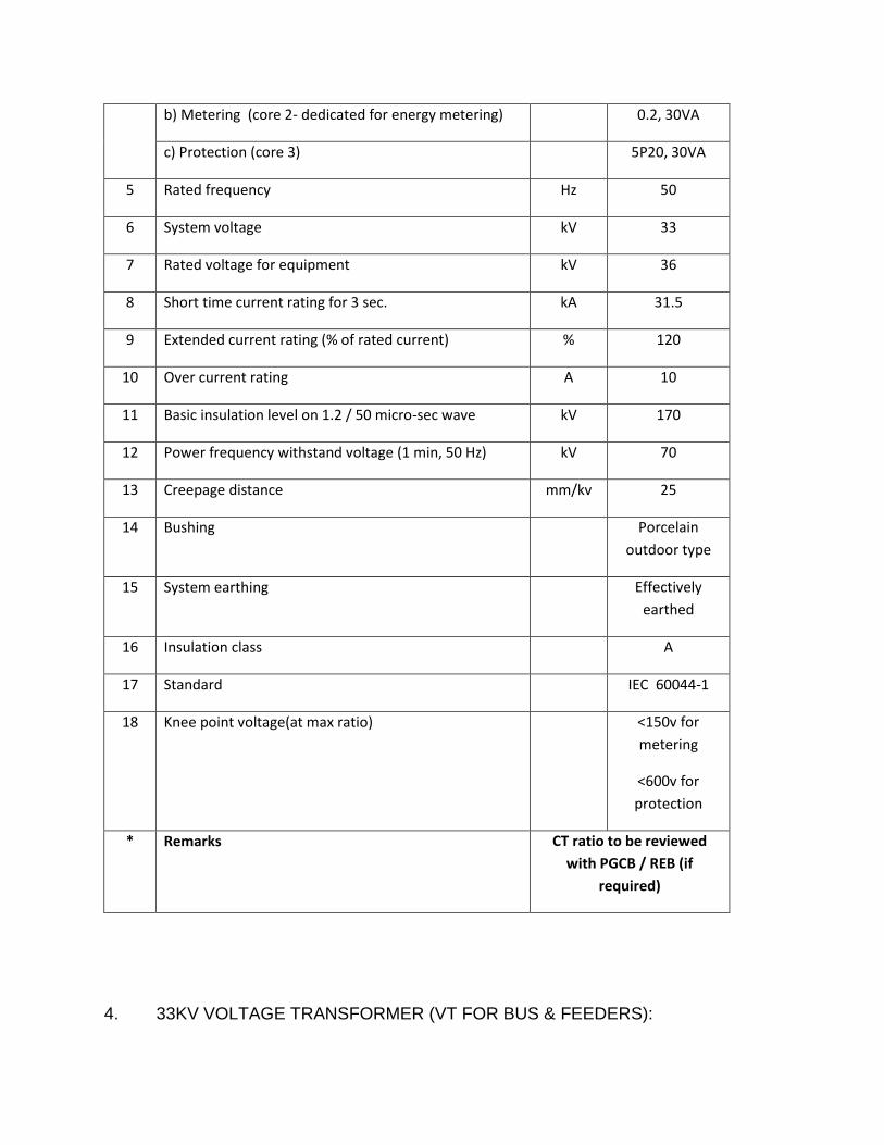
b) Metering (core 2- dedicated for energy metering) 0.2, 30VA
c) Protection (core 3) 5P20, 30VA
5 Rated frequency Hz 50
6 System voltage kV 33
7 Rated voltage for equipment kV 36
8 Short time current rating for 3 sec. kA 31.5
9 Extended current rating (% of rated current) % 120
10 Over current rating A 10
11 Basic insulation level on 1.2 / 50 micro-sec wave kV 170
12 Power frequency withstand voltage (1 min, 50 Hz) kV 70
13 Creepage distance mm/kv 25
14 Bushing Porcelain
outdoor type
15 System earthing Effectively
earthed
16 Insulation class A
17 Standard IEC 60044-1
18 Knee point voltage(at max ratio) <150v for
metering
<600v for
protection
* Remarks CT ratio to be reviewed
with PGCB / REB (if
required)
4. 33KV VOLTAGE TRANSFORMER (VT FOR BUS & FEEDERS):

(If Applicable)
Sl.
No.
Description Unit Requirements
1 Type Electromagnetic induction,
single phase, outdoor
2 Rated primary voltage kV 33/ 3
3 Rated voltage for secondary windings kV 0.11 / 3 and
0.11 / 3
4 Rated secondary burden and accuracy
Secondary winding
Core 1 (Dedicated for energy metering)
VA
Class
60
0.2
Secondary winding
Core 2
VA
Class
50
3P
5 Frequency Hz 50
6 Impulse withstand voltage (1.2/50 micro sec wave) kV 170
7 Cree page distance mm/kV 25
8 System earthing Effectively
earthed
9 Power frequency withstand voltage (1min) KV 70
10 Partial discharge PC ≤5
11 Short circuit withstand voltage KA 63
12 Rated voltage factor 1.2 continuous
1.9 30 second
13 Standard IEC 60044-2
5. 33KV LIGHTNING ARRESTER (LA)

Sl.
No.
Description Unit Requirement
1 Type Metal Oxide,
(ZnO)
Gapless type,
single phase
2 System voltage kV 33
3 Rated voltage kV 36
4 System frequency Hz 50
5 Continuous operating voltage kV 25 kV (rms)
6 Rated arrester voltage kV 30
7 Standard nominal discharge current kA 10
8 Reference current at ambient temperature mA 2
9 Steep current impulse residual voltage kV PK 84
10 Basic insulation level on 1.2 / 50 micro-sec wave kV 170
11 Power frequency withstand voltage (1.2/50 ms) kV 70
12 Lightning impulse residual voltage at 10kA kV PK 75
13 Duty Class Heavy Duty
Station Class
14 Earthing system Effectively
earthed
15 Discharge class 3
16 Pressure relief class Class A
17 Degree of Protection IP 55
18 Surge Counter & Current Monitor Yes
19 Standard IEC 60099-4
6. 33/0.415KV, 200KVA AUXILIARY TRANSFORMER (If applicable)
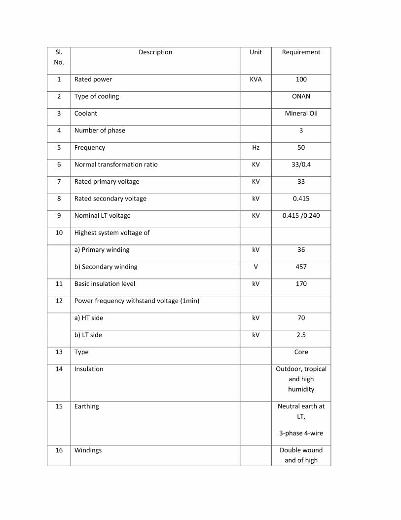
Sl.
No.
Description Unit Requirement
1 Rated power KVA 100
2 Type of cooling ONAN
3 Coolant Mineral Oil
4 Number of phase 3
5 Frequency Hz 50
6 Normal transformation ratio KV 33/0.4
7 Rated primary voltage KV 33
8 Rated secondary voltage kV 0.415
9 Nominal LT voltage KV 0.415 /0.240
10 Highest system voltage of
a) Primary winding kV 36
b) Secondary winding V 457
11 Basic insulation level kV 170
12 Power frequency withstand voltage (1min)
a) HT side kV 70
b) LT side kV 2.5
13 Type Core
14 Insulation Outdoor, tropical
and high
humidity
15 Earthing Neutral earth at
LT,
3-phase 4-wire
16 Windings Double wound
and of high

conductivity
copper
17 Vector Group DYN ll
18 Neutral to be Brought out
a) HT Nil
b) LT Yes
19 Neutral insulation Full insulation
and 100%
capacity
20 LT bushing Nos 4
21 Impedance voltage at 75 oC at normal ratio and rated
capacity
5%
22 Tapping range 5 steps off-load tap
changer, 2.5% per
step
23 Type of tap changer Manual
24 Maximum temperature rise over 40 oC ambient when
transformer is working at full load and tap changer is
at normal position
a) Winding by resistance oC 65
b) Oil by temperature oC 60
25 Type of base Ground mounted
7. 33KV BUSBARS AND CONNECTORS

Sl.
No.
Description Unit Requirement
A. FLEXIBLE CONDUCTORS
1 Conductor/connector material ACSR/ 2×Martin
2 Rated current (site rating) A 2500
3 Temperature rise at rated current oC 35
8. 33KV BUSBAR INSULATOR STRING
Sl.
No.
Description Unit Requirement
1 Insulator material Porcelain
2 Number of units per string nos. 4
3 Insulator voltage class
4 Type of insulator Ball and socket
type disc,
security clip
made of rod
brass alloy
5 Cree page/leakage distance (min) mm 298
6 Total Cree page distance of string mm 900
7 Unit spacing mm 146
8 Dry arcing distance (min) mm 1968
9 Diameter of insulator mm 256
10 Withstand voltage (min)
a) Power frequency dry (one min) kV 70
b) Power frequency wet(one min) kV 40

c) Impulse 1.2 / 50 micro sec kV 110
11 Flashover voltage (min)
a) Power frequency dry (one min) kV 80
b) Power frequency wet(one min) kV 50
c) 50% impulse 1.2 / 50 micro sec wave, positive or
impulse 1.2 / 50 micro sec wave positive
kV 125
d) 50% impulse 1.2 / 50 micro sec wave, negative kV 130
12 Power frequency puncture voltage (min) kV 110
13 Radio influence voltage data (min)
a) Power frequency test voltage rms to ground kV 10
b) Maximum RIV at 1000Kc micro V 50
14 Minimum mechanical strength for suspension
a) Electro-mechanical breaking load kg 7260
b) Mechanical breaking load kg 6800
c) Tension proof test load kg 3400
d) Time load test value kg 4536
e) Mechanical impact strength mm kg 630
15 Minimum mechanical strength for strain stringing
a) Electro-mechanical breaking load kg 11340
b) Mechanical breaking load kg 11340
c) Tension proof test load kg 3400
d) Time load test value kg 4536
e) Mechanical impact strength mm kg 530
16 Insulator hardware Insulator
hardware for
insulator strings

or bus support
insulator shall
have UTS-120
KN and
galvanized as per
IEC-729
9. SHIELD WIRE, EARTHING GRID AND EARTHING ELECTRODE
Sl.
No.
Description Unit Requirement
A. Shield Wires
1 Material High strength steel
2 Grade of steel kg. 4
3 Number of strands nos. 7
4 Diameter of each strand mm 3.25
5 Overall diameter mm 9.8
6 Nominal cross section mm2 35
7 Weight per km length kg 460
8 Rated ultimate tensile strength kg 4900
9 Class of Zinc coating Class-A
B Earth Grid
1 Material Copper
2 Maximum earth fault current for 3 sec kA 31.5
C Earth Electrodes
1 Material Copper
2 Diameter mm 16
3 Calculated resistance of combined earth grid Ohm Less than 0.5

10. BATTERIES AND CHARGER (If Applicable)
Sl.
N0.
Description Unit Requirements
A. BATTERY
1 Electrolyte type Nickel Cadmium
/ Alkaline
2 Nominal voltage V/per
cell
1.2
3 Capacity at 5 hour rate Ah 250
4 Number of cells nos. 92
5 Operating voltage VDC 110
6 Continuous discharge current at the rate of 10 hour and
final cell voltage 1.1 volt
Amp 10
7 Short time discharge current at the rate of 2 hour and
final cell voltage 1.1 volt
Amp 50
8 Discharge voltage V 1.0 – 1.4 per
cell
9 Charging voltage (normal) V 1.4-1.5Volt per
cell
10 Charging voltage (Maximum) V 1.54-1.69 per
cell
11 Battery voltage at end of the duty cycle V 1.1Volt per cell
B. CHARGER
1 Rectifier Type (Thyristor
Controlled)
Silicon or
Selenium
2 AC input voltage V 415V±15%, 3

phase
3 Input a.c frequency HZ 50±5%
4 DC output voltage range V DC 110±10%
a) normal charge V DC 110±10%
b) Float charge V DC 1.42 volt per
cell 110±5%
c) Boast charge V DC 1.55 volt per
cell
5 Installation breakdown voltage kV 2kV for 1
minute
6 Output Current (continuous) A DC 50
7 Type of AVR DVR-Diode
Voltage
Regulator
8 Installation Indoor
9 Charging Mode: Both constant
current &
constant
Voltage
11. LV AC DC DISTRIBUTION BOARD
Sl.
No.
Description Unit Requirement
A. AC DISTRIBUTION BOARD
1 Bus bar rating (R, Y, B, N, G) Amps 600
2 Voltage Volts 415
3 Incoming breaker rating (MCCB) Amps 400

B. D.C. DISTRIBUTION BOARD
1 Bus bars:- (+VE,-VE, G)
a) Maximum current rating A DC 200
b) Voltage rating V DC 110
C. Two distribution bus shall be maintained in each pannel (AC & DC Distribution) and
both shall be electricity interlocked.
12. 33KV CONTROL, METERING AND RELAY PANEL
Sl.No. Description Unit Requirement
A. 33KV CONTROL PANEL
1 Number of control panelsKVRH Meter
Panel
Nos 1
2 Number of KWH Metering Panel No. 1
A1. PROTECTION
A.1.1 IDMT OVER CURRENT & EARTH FAULT
RELAYS
1 Manufacturer’s Name & Country Siemens (Germany)/ Alstom (UK/France)/
ABB (Switzerland/Sweden)/
Schneider (France) 2 Type of relay Numerical
Programmable
3 Range of current setting
a) Phase element % of CT rating
b) Earth fault element % of CT rating
4 Range of timing settings at 10 time CT
rating
Sec
5 Burden of relay at 10 time CT rating VA

6 Percentage of current setting at which
relay will reset
%
7 Reset time after removal of 10 times
CT rated current for:
a) Phase element (100%) Sec
b) E/F element (40%) Sec
A2.
METERING AND INDICATION
A.2.1 KWH METER
1 Manufacturer’s Name & Country Siemens(Germany/Switzerl
and)/Alstom,(UK)/ABB(Swi
tzerland)/AEG(Germany)/S
chlumberger(USA)
2 Type of Meter Numerical
Programmable
multifunction(3 element
4-wire)
3 Number of KWH Meters Nos. 02 nos. with provision
for 04 meters in the
Metering panel
A.2.2 INDICATION METERS (VOLT, AMPERE,
KW, KVAR, PF)
1 Manufacturer Siemens(Germany/Switz
erland)/Alstom,(UK)/AB
B(Switzerland)/AEG(Ger
many)/Schlumberger
(USA)
2 Type of Meter Digital /Analog
3 Type of Meters in each Panel Volt, 3 nos. Amp, kW,
kVAR and Pf

13. STEEL STRUCTURE DESIGN
Sl.
N0.
Description Unit Requirements
1 Maximum ratio slenderness
a) Main members mm 120
b) Bracings mm 180
c) Redundant mm. 250
2 Minimum size of member mm 45455
3 Min member thickness
Main member mm 6
Other bracing member mm 5
Plate mm 5
Bolt diameter mm 16
4 Galvanizing thickness mm 85
14. Control cable
XLPE insulated multi core control cable Laid up beded with PVC or tap. Flat/round wire armoring with helical steel
taping and PVC sheathed, rated voltage 600/1000, continuous permissible voltage 720/1200 volts (VDE 027/3.69
BDS 901:85) (NYRGby) suitable for use in indoors, outdoors, underground and in water for continuous permissible
service voltage of 720/1200 volts. Maximum resistance 4.73 ohm/km at 35°C.
15. POWER CABLES
15.1. 33 KV POWER CABLES (U/G)

Guaranteed Technical Data Schedule of 33KV, 1-Core × 500 Sq.mm U/G XLPE Copper Cable
SL
No.
Description Unit Required Specification
1 Name and address of the
Manufacturer
To be mentioned
2 Type/Model of the offered cable To be mentioned
3 Nominal system voltage KV 33
4
Rated voltage of cable KV 18/30(36)
5 Process of manufacturing VCV/CCV
6 Number of core and cross
sectional area of conductor cores
Sq.mm 1×500
7 Conductor material Copper
8 Minimum no of strand No. 53
9 Diameter of each strand mm To be mentioned
10 Shape of conductor Compacted Circular
11 Type of conductor screen Semi-conducting
12 Thickness of semi conducting
screen
mm 0.6
13 Avg. thickness of insulation mm 8.0
14 Process of curing Dry process
15 Material of insulation Cross Linked Polyethylene (XLPE)
16 Type of non metallic insulating
screen
Semi-conducting
17 Thickness of semi conducting
insulation screen
mm 1.0
18 Number and diameter of copper
screen strands
No./mm Based on design calculation
19 Composition of filler PVC

20 Composition of bedding Extruded PVC
21 Thickness of bedding mm Based on design calculation
22 Number and diameter of armour
wire
No./mm As per IEC 60502
23 Avg. thickness of MDPE over
sheath
mm Based on design calculation
24 Nominal diameter of complete
cable
mm Based on design calculation
25 Nominal weight per meter of
complete cable
Kg/m Based on design calculation
26 Minimum radius of bend round
which cable can be laid
mm Based on design calculation
27 Max. D.C resistance of conductor
per meter at 20 C
Ohm/m Based on design calculation
28 Max. A.C resistance of conductor
per meter at MAXIMUM
CONDUCTOR TEMPARATURE
Ohm/m Based on design calculation
29 Star resistance per meter of cable
at 50Hz
Ohm/m Based on design calculation
30 Star capacitance per per meter of
cable at 50Hz
pF/m Based on design calculation
31 Charging current per conductor
per meter at 18000/30000 Volts ,
50Hz
mA Based on design calculation
32 Maximum current carrying
capacity of conductor in ground
A Based on design calculation
33 Maximum conductor temperature
under continuous loading
C Based on design calculation
34 Short circuit withstand capacity
nof the cable for 1 sec. duration
KA Min. 25
35 conductor temperature at the end
of short circuit
C ≤250
36 Earth fault withstand capacity for KA Min. 25

1 sec.
37
Screen short circuit withstand
capacity
KA Min. 25
38 Armour short circuit capacity KA Based on design calculation
39
Cable resistance, reactance
a) for positive sequence Ohm/m Based on design calculation
b) negative sequence Ohm/m Based on design calculation
c) Zero sequence Ohm/m Based on design calculation
BANGLADESH RURAL ELECTRIFICATION BOARD

TENDER DOCUMENT
FOR
TURNKEY CONTRACT FOR DESIGN, SUPPLY, CONSTRUCTION, INSTALLATION, TESTING & COMMISSIONING
WORK FOR EXTENSION OF 33KV NEW BAY AT 132/33 KV ISHWARDI GRID SUB-STATION FOR PABNA PBS- 1
UNDER BREB.
SCHEDULE B
TENDER PRICES
BANGLADESH RURAL ELECTRIFICATION BOARD

TURNKEY CONTRACT FOR DESIGN, SUPPLY, CONSTRUCTION, INSTALLATION, TESTING & COMMISSIONING
WORK FOR EXTENSION OF 33KV NEW BAY AT 132/33 KV ISHWARDI GRID SUB-STATION FOR PABNA PBS- 1
UNDER BREB.
SCHEDULE B
TENDER PRICES
The Tenderer is to complete in full the following Price Schedule in accordance with BOQ described in section-6 of this Tender Document.
Each item is to be priced separately for switching station & 33KV Line Augmentation work and is to be fully
inclusive of all costs associated with completing the Works. The prices are to include for surveying, design,
fabrication, manufacture, assembly, quality control, testing, packing, insurance, delivery to site. The estimated
cost of elements are to be shown in the appropriate column in the schedule shall include landing, haulage,
transport to site, civil works, erection, construction, assembly, connecting, testing finishing of, setting to work
and maintenance during the defect liability period including all supervision, project management costs,
overheads, on-costs and profits etc.
The Works shall be valued and paid exclusively at the unit prices and total prices quoted in the schedule, which
are to remain fixed for the duration of the Contract.
The prices quoted are to be firm for the completed Works in full working order in accordance with the
requirements of the Contract.

Prices for the equipment at site, erection/ supervision elements are to be quoted in Bangladesh Taka inclusive of
all duties and taxes paid or payable on components and material incorporated or to be incorporated in the plant.
Prices shall also include for all necessary local materials, inland transportation, insurance etc.

BANGLADESH RURAL ELECTRIFICATION BOARD
TENDER DOCUMENT
FOR
TURNKEY CONTRACT FOR DESIGN, SUPPLY, CONSTRUCTION, INSTALLATION, TESTING & COMMISSIONING
WORK FOR EXTENSION OF 33KV NEW BAY AT 132/33 KV ISHWARDI GRID SUB-STATION FOR PABNA PBS- 1
UNDER BREB
SCHEDULE C
BAR CHART PROGRAMME OF KEY ACTIVITIES
BANGLADESH RURAL ELECTRIFICATION BOARD
TURNKEY CONTRACT FOR DESIGN, SUPPLY, CONSTRUCTION, INSTALLATION, TESTING & COMMISSIONING
WORK FOR EXTENSION OF 33KV NEW BAY AT 132/33 KV ISHWARDI GRID SUB-STATION FOR PABNA PBS- 1
UNDER BREB.
SCHEDULE C
BAR CHART PROGRAMME OF KEY ACTIVITIES
The individual dates are all contractually bindings.
The times given under column C are the commissioning target dates at present planned to be achieved and may
be the subject of mutual adjustment.
The times entered under column A are to be the dates guaranteed for arrival at site of the equipment before
plant erection to the extent necessary to enable him to proceed with work to meet the dates under column B
guaranteed for complete delivery, erection and commissioning.
The time include all necessary control, relay, metering, auxiliary power, ancillary equipment to enable the
respective item of plant to be completely commissioned and put into commercial operation together with such
other associated equipment, e.g. bus-bars etc. as will ensure that subsequent shutdown are unnecessary for at
least only of a temporary or short time nature.
List of
Equipment
A*
Guaranteed Arrival at
site
B*
Guaranteed
Completion
C*
Target Completion
* Time in months, after signing of Contract.
Preliminary foundation drawings as called for in the Technical Specification shall be provided within 1.0 month of
the contract commencing date.

BANGLADESH RURAL ELECTRIFICATION BOARD
TENDER DOCUMENT
FOR
TURNKEY CONTRACT FOR DESIGN, SUPPLY, CONSTRUCTION, INSTALLATION, TESTING & COMMISSIONING
WORK FOR EXTENSION OF 33KV NEW BAY AT 132/33 KV ISHWARDI GRID SUB-STATION FOR PABNA PBS- 1
UNDER BREB.
SCHEDULE D
MANUFACTURERS, PLACES OF MANUFACTURE AND TESTING

BANGLADESH RURAL ELECTRIFICATION BOARD
TURNKEY CONTRACT FOR DESIGN, SUPPLY, CONSTRUCTION, INSTALLATION, TESTING & COMMISSIONING
WORK FOR EXTENSION OF 33KV NEW BAY AT 132/33 KV ISHWARDI GRID SUB-STATION FOR PABNA PBS- 1
UNDER BREB.
SCHEDULE D
MANUFACTURERS, PLACES OF MANUFACTURE AND TESTING
Item Description Manufacturer Place of
Manufacture
Place of Testing and
Inspection
1. 33KV SWITCHGEAR
Circuit Breakers (VCB)
Operating Mechanism
Disconnecting Switch (DS)
Earthing Switch (ES)
Busbar
Connector
Lightning Arrester (LA)
Voltage Transformer (VT)
Current Transformer (CT)

Insulator Disc Insulator Post Type DO Fuse Remote Control Panel Relays Indicating Instrument Energy Meters Battery Charger Battery LVAC Panel DC Panel LV Power & Control Cables
2. STEEL STRUCTURES
3. EARTHING
Copper Conductor
4. SITE ERECTION AND
COMMISSIONING BY
5. CIVIL WORKS
Design to be performed by:
Construction by:
6. All materials for Augmentation
of 33 KV existing line.

BANGLADESH RURAL ELECTRIFICATION BOARD
TENDER DOCUMENT
FOR
TURNKEY CONTRACT FOR DESIGN, SUPPLY, CONSTRUCTION, INSTALLATION, TESTING & COMMISSIONING
WORK FOR EXTENSION OF 33KV NEW BAY AT 132/33 KV ISHWARDI GRID SUB-STATION FOR PABNA PBS- 1
UNDER BREB.
SCHEDULE E
TECHNICAL PARTICULARS AND GUARRANTEES

BANGLADESH RURAL ELECTRIFICATION BOARD
TURNKEY CONTRACT FOR DESIGN, SUPPLY, CONSTRUCTION, INSTALLATION, TESTING & COMMISSIONING
WORK FOR EXTENSION OF 33KV NEW BAY AT 132/33 KV ISHWARDI GRID SUB-STATION FOR PABNA PBS- 1
UNDER BREB.
SCHEDULE E
TECHNICAL PARTICULARS AND GUARRANTEES

1.0 33KV OUTDOOR TYPE VACUUM CIRCUIT BREAKER (VCB)
1.1 33KV OUTDOOR TYPE VACUUM CIRCUIT BREAKER (FEEDER BREAKER)
Sl.
No.
Description Unit Requirement Manufacturer’s
Guaranteed Data
1 Manufacturer To be mentioned
2 Model number To be mentioned
3 Number of phases 3
4 No. of break per phase To be mentioned
5 Interrupting medium Vacuum
6 Vacuum interrupter’s manufacturer To be mentioned
7 Rated voltage KV 33
8 Maximum voltage KV 36
9 Rated frequency HZ 50
10 Rated normal current for outgoing feeder A 1250
11 Rated breaking currents: Arms
a) Line charging A 25
b) Cable charging A 50
c) Small inductive A 02
12 Rated short-circuit breaking current KA rms 31.5
13 First pole to clear factor To be mentioned
14 Rated transient recovery voltage at 100% rated short circuit
breaking current
KV To be mentioned
15 Rated short-circuit making current KA 78.75
16 Rated operating sequence O-0.3s-CO-3min-C
17 Rated duration of short-circuit S 3
18 Rated out of phase breaking current KA To be mentioned
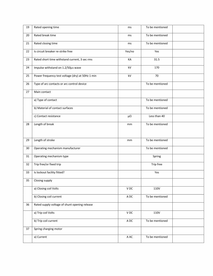
19 Rated opening time ms To be mentioned
20 Rated break time ms To be mentioned
21 Rated closing time ms To be mentioned
22 Is circuit breaker re-strike free Yes/no Yes
23 Rated short time withstand current, 3 sec rms KA 31.5
24 Impulse withstand on 1.2/50s wave kV 170
25 Power frequency test voltage (dry) at 50Hz 1 min kV 70
26 Type of arc contacts or arc control device To be mentioned
27 Main contact
a) Type of contact To be mentioned
b) Material of contact surfaces To be mentioned
c) Contact resistance µΩ Less than 40
28 Length of break mm To be mentioned
29 Length of stroke mm To be mentioned
30 Operating mechanism manufacturer To be mentioned
31 Operating mechanism type Spring
32 Trip free/or fixed trip Trip free
33 Is lockout facility fitted? Yes
35 Closing supply
a) Closing coil Volts V DC 110V
b) Closing coil current A DC To be mentioned
36 Rated supply voltage of shunt opening release
a) Trip coil Volts V DC 110V
b) Trip coil current A DC To be mentioned
37 Spring charging motor
a) Current A AC To be mentioned

b) Voltage AC V AC 415/230
38 Number of auxiliary switch contacts
a) normally open NO 9
b) normally closed NC 9
c) adjustable As required
39 Maximum creepage
a) to earth mm To be mentioned
b) across interrupter terminals mm To be mentioned
40 Number of interrupters per pole Nos 1
41 Material of interrupter chamber To be mentioned
42 Wall thickness of interrupter chamber mm To be mentioned
a) Material of contact surface primary arcing To be mentioned
b) Contact resistance To be mentioned
43 Length of each break mm To be mentioned
44 Length of stroke mm To be mentioned
45 Operating rod for moving contact(s) material To be mentioned
46 Dimensions etc. To be mentioned
47 Weight of circuit breaker unit complete kg To be mentioned
48 Maximum shock load imposed on floor or foundations when
opening under fault conditions (state whether tension or
compression)
N To be mentioned
49 Period of time equipment has been in commercial operation To be mentioned
50 Opening time
a) Without current at 100% of rated breaking current sec 0.5 max
b) Breaking time cycle 5 (0.1 second)
c) Closing time ms 70±10
51 Maximum arc duration at any duty cycle of IEC 56-2 ms
at........%
To be mentioned

52 Current at which maximum arc duration occurs (critical current) A To be mentioned
53 Make time ms To be mentioned
54 Time from closing of control switch to completion of closing
stroke during fault making
ms To be mentioned
55 Is an external series break incorporated in the breaker? Yes/no To be mentioned
56 Is any device used to limit transient recovery voltage? Yes/no To be mentioned
57 Number of close/trip operation possible on one spring charge Nos. To be mentioned
Sl.
No.
Description Unit Requirement Manufacturer’s
Guaranteed Data
58 Minimum clearance in air:
a) between phases mm 430
b) phase to earth mm 380
c) across interrupters mm To be mentioned
d) live parts to ground level mm To be mentioned
59 Period of time the equipment has been in commercial
operation
Years To be mentioned
60 Cree page distance (min) kV/mm 25
61 Method of indicating VCB ON/OFF Mech/Elect To be mentioned
62 Life of interrupter Years To be mentioned
63 Pressure in vacuum tube for VCB Bar To be mentioned
64 Guaranteed numbers of operation for vacuum interrupter
a) at rated crrent switching Nos. To be mentioned
b) at short circuit current switching Nos. To be mentioned
65 All current carrying parts of VCB shall be made of Copper
66 Standard IEC 56
67 Degree of Protection IP 55
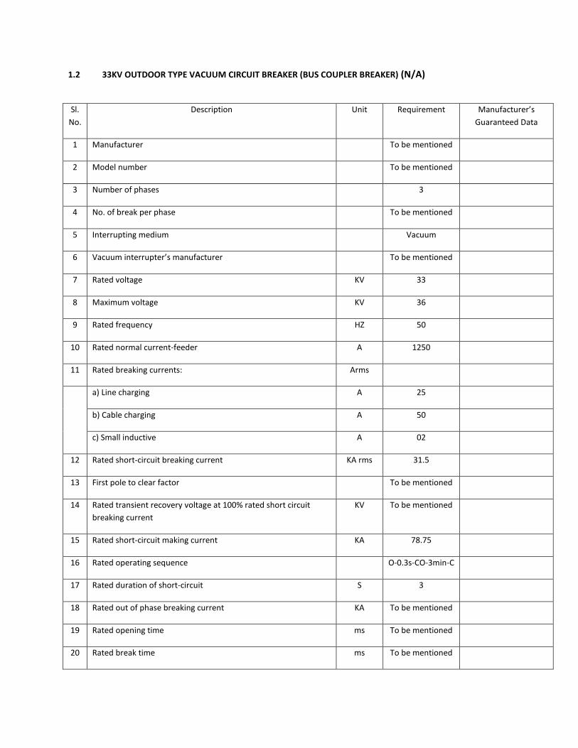
1.2 33KV OUTDOOR TYPE VACUUM CIRCUIT BREAKER (BUS COUPLER BREAKER) (N/A)
Sl.
No.
Description Unit Requirement Manufacturer’s
Guaranteed Data
1 Manufacturer To be mentioned
2 Model number To be mentioned
3 Number of phases 3
4 No. of break per phase To be mentioned
5 Interrupting medium Vacuum
6 Vacuum interrupter’s manufacturer To be mentioned
7 Rated voltage KV 33
8 Maximum voltage KV 36
9 Rated frequency HZ 50
10 Rated normal current-feeder A 1250
11 Rated breaking currents: Arms
a) Line charging A 25
b) Cable charging A 50
c) Small inductive A 02
12 Rated short-circuit breaking current KA rms 31.5
13 First pole to clear factor To be mentioned
14 Rated transient recovery voltage at 100% rated short circuit
breaking current
KV To be mentioned
15 Rated short-circuit making current KA 78.75
16 Rated operating sequence O-0.3s-CO-3min-C
17 Rated duration of short-circuit S 3
18 Rated out of phase breaking current KA To be mentioned
19 Rated opening time ms To be mentioned
20 Rated break time ms To be mentioned

21 Rated closing time ms To be mentioned
22 Is circuit breaker re-strike free Yes/no Yes
23 Rated short time withstand current, 3 sec rms KA 31.5
24 Impulse withstand on 1.2/50s wave kV 170
25 Power frequency test voltage (dry) at 50Hz 1 min kV 70
26 Type of arc contacts or arc control device To be mentioned
27 Main contact
a) Type of contact To be mentioned
b) Material of contact surfaces To be mentioned
c) Contact resistance µΩ Less than 40
28 Length of break mm To be mentioned
29 Length of stroke mm To be mentioned
30 Operating mechanism manufacturer To be mentioned
31 Operating mechanism type Spring
32 Trip free/or fixed trip Trip free
33 Is lockout facility fitted? Yes
35 Closing supply
a) Closing coil Volts V DC 110V
b) Closing coil current A DC To be mentioned
36 Rated supply voltage of shunt opening release
a) Trip coil Volts V DC 110V
b) Trip coil current A DC To be mentioned
37 Spring charging motor
a) Current A AC To be mentioned
b) Voltage AC V AC 415/230
38 Number of auxiliary switch contacts
a) normally open NO 9

b) normally closed NC 9
c) adjustable As required
39 Maximum cree page
a) to earth mm To be mentioned
b) across interrupter terminals mm To be mentioned
40 Number of interrupters per pole Nos 1
41 Material of interrupter chamber To be mentioned
42 Wall thickness of interrupter chamber mm To be mentioned
a) Material of contact surface primary arcing To be mentioned
b) Contact resistance To be mentioned
43 Length of each break mm To be mentioned
44 Length of stroke mm To be mentioned
45 Operating rod for moving contact(s) material To be mentioned
46 Dimensions etc. To be mentioned
47 Weight of circuit breaker unit complete kg To be mentioned
48 Maximum shock load imposed on floor or foundations when
opening under fault conditions (state whether tension or
compression)
N To be mentioned
49 Period of time equipment has been in commercial operation To be mentioned
50 Opening time
a) Without current at 100% of rated breaking current sec 0.5 max
b) Breaking time cycle 5 (0.1 second)
c) Closing time ms 70±10
51 Maximum arc duration at any duty cycle of IEC 56-2 ms at......% To be mentioned
52 Current at which maximum arc duration occurs (critical current) A To be mentioned
53 Make time ms To be mentioned
54 Time from closing of control switch to completion of closing
stroke during fault making
ms To be mentioned

55 Is an external series break incorporated in the breaker? Yes/no To be mentioned
56 Is any device used to limit transient recovery voltage? Yes/no To be mentioned
57 Number of close/trip operation possible on one spring charge Nos. To be mentioned
58 Minimum clearance in air:
a) between phases mm 430
b) phase to earth mm 380
c) across interrupters mm To be mentioned
d) live parts to ground level mm To be mentioned
59 Period of time the equipment has been in commercial
operation
Years To be mentioned
60 Cree page distance (min) kV/mm 25
61 Method of indicating VCB ON/OFF Mech/El
ect
To be mentioned
62 Life of interrupter Years To be mentioned
63 Pressure in vacuum tube for VCB Bar To be mentioned
64 Guaranteed numbers of operation for vacuum interrupter
a) at rated crrent switching Nos. To be mentioned
b) at short circuit current switching Nos. To be mentioned
65 All current carrying parts of VCB shall be made of Copper
66 Standard IEC 56
67 Degree of Protection IP 55

2. 33KV DISCONNECTING SWITCH AND EARTHING SWITCH (DS/ES)
2.1. 33KV DISCONNECTING SWITCH (AT BUS SIDE FOR INCOMING) (If applicable)
Sl.
No.
Description Unit Requirement Manufacturer’s
Guaranteed Data
1 Manufacturer To be mentioned
2 Model number To be mentioned
3 Operating system Vertical
4 System voltage kV 33
5 Rated voltage kV 36
6 Frequency Hz 50
7 Number of pole Nos. 3
8 Rated normal current A 2000
9 Rated short time withstand current for 3 sec kA rms 31.5
10 Rated duration of short circuit Sec 3
11 Rated peak withstand current kA pk 78.75
12 Basic insulation level kV 170
13 Installation Outdoor
14 Type Air
15 Construction Open
16 Method of operation Gang operated,
17 Type of operating mechanism Manual
18 Mounting position Vertical
19 Type of contact To be mentioned
20 Materiall of contact service To be mentioned
21 Manual operating torque KNm To be mentioned
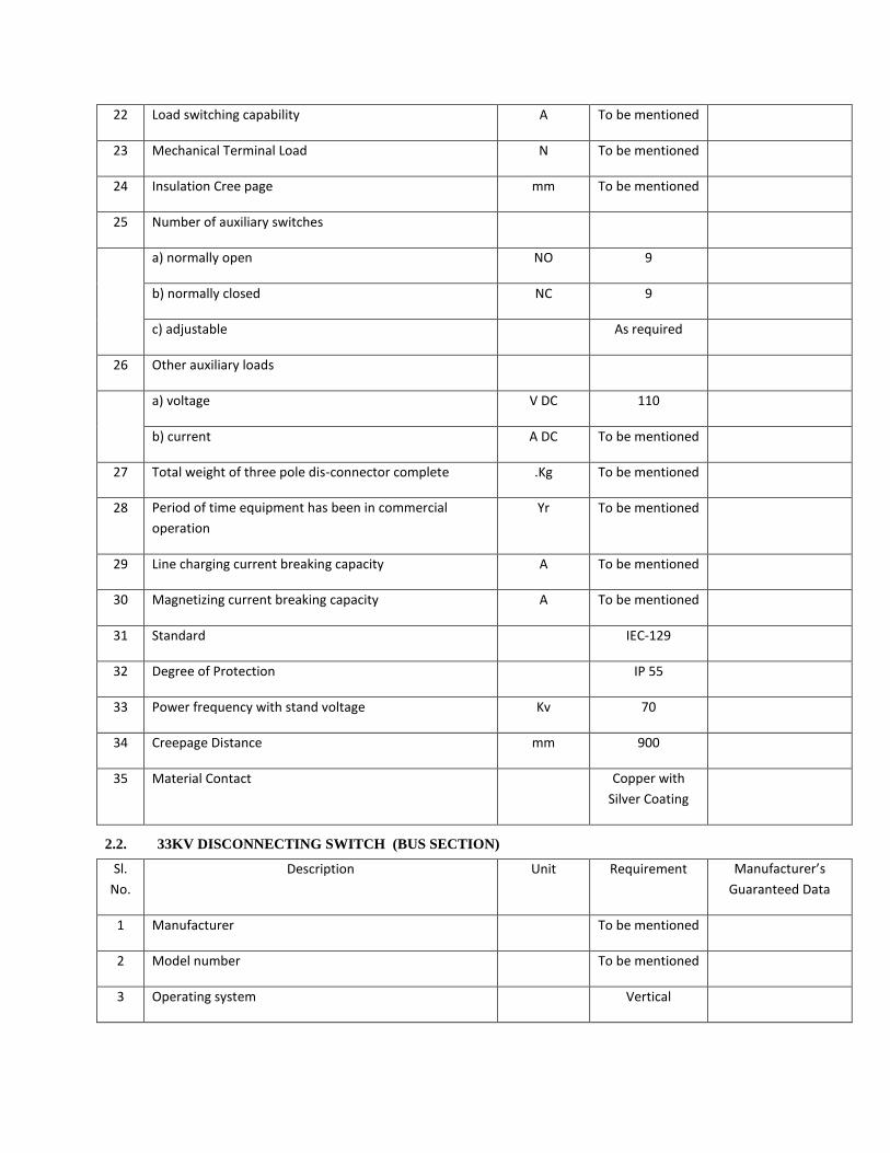
22 Load switching capability A To be mentioned
23 Mechanical Terminal Load N To be mentioned
24 Insulation Cree page mm To be mentioned
25 Number of auxiliary switches
a) normally open NO 9
b) normally closed NC 9
c) adjustable As required
26 Other auxiliary loads
a) voltage V DC 110
b) current A DC To be mentioned
27 Total weight of three pole dis-connector complete .Kg To be mentioned
28 Period of time equipment has been in commercial
operation
Yr To be mentioned
29 Line charging current breaking capacity A To be mentioned
30 Magnetizing current breaking capacity A To be mentioned
31 Standard IEC-129
32 Degree of Protection IP 55
33 Power frequency with stand voltage Kv 70
34 Creepage Distance mm 900
35 Material Contact Copper with
Silver Coating
2.2. 33KV DISCONNECTING SWITCH (BUS SECTION)
Sl.
No.
Description Unit Requirement Manufacturer’s
Guaranteed Data
1 Manufacturer To be mentioned
2 Model number To be mentioned
3 Operating system Vertical

4 System voltage kV 33
5 Rated voltage kV 36
6 Frequency Hz 50
7 Number of pole Nos. 3
8 Rated normal current A 2500
9 Rated short time withstand current for 3 sec kA rms 31.5
10 Rated duration of short circuit Sec 3
11 Rated peak withstand current kA pk 78.75
12 Basic insulation level kV 170
13 Installation Outdoor
14 Type Air
15 Construction Open
16 Method of operation Gang operated,
17 Type of operating mechanism Manual
18 Mounting position Vertical
19 Type of contact To be mentioned
20 Materiall of contact service To be mentioned
21 Manual operating torque KNm To be mentioned
22 Load switching capability A To be mentioned
23 Mechanical Terminal Load N To be mentioned
24 Insulation Cree page mm To be mentioned
25 Number of auxiliary switches
a) normally open NO 9
b) normally closed NC 9
c) adjustable As required
26 Other auxiliary loads

a) voltage V DC 110
b) current A DC To be mentioned
27 Total weight of three pole dis-connector complete .Kg To be mentioned
28 Period of time equipment has been in commercial
operation
Yr To be mentioned
29 Line charging current breaking capacity A To be mentioned
30 Magnetizing current breaking capacity A To be mentioned
31 Standard IEC-129
32 Degree of Protection IP 55
33 Power frequency with stand voltage Kv 70
34 Creepage Distance 900
35 Material Contact Copper with
Silver Coating
2.3. 33KV DISCONNECTING SWITCH (FOR FEEDERS AT BUS SIDE)
Sl.
No.
Description Unit Requirement Manufacturer’s
Guaranteed Data
1 Manufacturer To be mentioned
2 Model number To be mentioned
3 Operating system Vertical
4 System voltage kV 33
5 Rated voltage kV 36
6 Frequency Hz 50
7 Number of pole Nos. 3
8 Rated normal current A 1250
9 Rated short time withstand current for 3 sec kA rms 31.5
10 Rated duration of short circuit Sec 3

11 Rated peak withstand current kA pk 78.75
12 Basic insulation level kV 170
13 Installation Outdoor
14 Type Air
15 Construction Open
16 Method of operation Gang operated,
17 Type of operating mechanism Manual
18 Mounting position Vertical
19 Type of contact To be mentioned
20 Materiall of contact service To be mentioned
21 Manual operating torque KNm To be mentioned
22 Load switching capability A To be mentioned
23 Mechanical Terminal Load N To be mentioned
24 Insulation Cree page mm To be mentioned
25 Number of auxiliary switches
a) normally open NO 9
b) normally closed NC 9
c) adjustable As required
d) Earting blade 6
26 Other auxiliary loads
a) voltage V DC 110
b) current A DC To be mentioned
27 Total weight of three pole dis-connector complete .Kg To be mentioned
28 Period of time equipment has been in commercial
operation
Yr To be mentioned
29 Line charging current breaking capacity A To be mentioned

30 Magnetizing current breaking capacity A To be mentioned
31 Standard IEC-129
32 Degree of Protection IP 55
33 Power frequency with stand voltage Kv 70
34 Creepage Distance 900
35 Material Contact Copper with
Silver Coating
2.4. 33KV DISCONNECTING SWITCH AND EARTHING SWITCH (FEEDER SIDE)
Sl.
No.
Description Unit Requirement Manufacturer’s
Guaranteed Data
1 Manufacturer To be mentioned
2 Model number To be mentioned
3 Operating system Vertical
4 System voltage kV 33
5 Rated voltage kV 36
6 Frequency Hz 50
7 Number of pole Nos. 3
8 Rated normal current A 1250
9 Rated short time withstand current for 3 sec kA rms 31.5
10 Rated duration of short circuit Sec 3
11 Rated peak withstand current kA pk 78.75
12 Basic insulation level kV 170
13 Installation Outdoor
14 Type Air

15 Construction Open
16 Method of operation Gang operated,
17 Type of operating mechanism Manual
18 Mounting position Vertical
19 Type of contact To be mentioned
20 Materiall of contact service To be mentioned
21 Manual operating torque KNm To be mentioned
22 Load switching capability A To be mentioned
23 Mechanical Terminal Load N To be mentioned
24 Insulation Cree page mm To be mentioned
25 Number of auxiliary switches
a) normally open NO 9
b) normally closed NC 9
c) adjustable As required
d) Earthing blade 6
26 Other auxiliary loads
a) voltage V DC 110
b) current A DC To be mentioned
27 Total weight of three pole dis-connector complete .Kg To be mentioned
28 Period of time equipment has been in commercial
operation
Yr To be mentioned
29 Line charging current breaking capacity A To be mentioned
30 Magnetizing current breaking capacity A To be mentioned
31 Standard IEC-129
32 Degree of Protection IP 55
33 Power frequency with stand voltage Kv 70

34 Creepage Distance 900
35 Material Contact Copper with
Silver Coating
3. 33KV CURRENT TRANSFORMER (CT)
3.1 33KV CURRENT TRANSFORMER (BUS COUPLER) (If applicable)
Sl.
No.
Description Unit Requirement Manufacturer’s
Guaranteed Data
1 Manufacturer To be mentioned
2 Model number To be mentioned
3 Standard IEC 185 or
equivalent
4 Installation Outdoor type
mounted on
galvanized steel
structure
5 Type Electromagnetic
induction, single
phase, outdoor,
oil/ Synthetic
6 Bushing Porcelain
7 Major insulation Low oil content
outdoor type
8 Application Protection/
metering
9 Rated secondary accuracy and burden
a) Metering (core 1- for indicating metering) 0.2, 50VA
b) Metering (core 2- for energy metering) 0.2, 50VA
c) Protection (core 3) 5P20, 50VA
10 Rated primary current Arms 2400-1600/5-5-
5A

11 Rated secondary current Arms 5-5-5A
12 Extended current rating % 120
13 Over current rating A 10
13 Short time current rating kA 25 for 3 sec
14 No of core 3
15 System voltage kV 33
16 Rated voltage kV 36
17 Rated frequency Hz 50
18 Basic insulation level on 1.2 / 50 micro sec wave kV 170
19 Power frequency withstand voltage (1 min, 50Hz) kV 70
20 Insulator cree page (phase to earth) mm/kV 25
21 Rated dynamic current kA pk 100
22 Insulation class A
23 Is earth screen fitted between primary and secondary
windings
Yes
24 Extended Current Rating (% of rated current) % 120
25 Over Current Rating A 10
26 Knee point voltage V To be mentioned
27 System earthing Effectively
earthed
28 Standard - As per relevant
IEC-185

3.2 33KV CURRENT TRANSFORMER (FEEDER)
Sl.
No.
Description Unit Requirement Manufacturer’s
Guaranteed Data
1 Manufacturer To be mentioned
2 Model number To be mentioned
3 Standard IEC 185 or
equivalent
4 Installation Outdoor type
mounted on
galvanized steel
structure
5 Type Electromagnetic
induction, single
phase, outdoor,
oil/ Synthetic
6 Bushing Porcelain
7 Major insulation Low oil content
outdoor type
8 Application Protection/
metering
9 Rated secondary accuracy and burden
a) Metering (core 1) 0.2, 30VA
b) Protection (core 2) 5P20, 30VA
10 Rated primary current Amps 800-400/5-5-5A
11 Rated secondary current Amps 5-5-5A
12 Extended current rating % 120
13 Over current rating A 10
13 Short time current rating kA 31.5 for 3 sec
14 No of core 3
15 System voltage kV 33

16 Rated voltage kV 36
17 Rated frequency Hz 50
18 Basic insulation level on 1.2 / 50 micro sec wave kV 170
19 Power frequency withstand voltage (1 min, 50Hz) kV 70
20 Insulator cree page (phase to earth) mm/kV 25
21 Rated dynamic current kA pk 100
22 Insulation class A
23 Is earth screen fitted between primary and secondary
windings
Yes
24 Extended Current Rating (% of rated current) % 120
25 Over Current Rating A 10
26 Knee point voltage V To be mentioned
27 System earthing Effectively
earthed
28 Standard - As per relevant
IEC-185

4. 33KV VOLTAGE TRANSFORMER (VT FOR BUS) If Applicable
Sl.
No.
Description Unit Requirement Manufacturer’s
Guaranteed Data
1 Manufacture To be mentioned
2 Model number To be mentioned
3 Installation Outdoor type
mounted on
galvanized steel
structure
4 Type Electromagnetic
induction, single
phase, outdoor,
Oil
5 Bushing Porcelain
6 Application Protection and
metering
7 Major insulation Low oil content
8 System voltage kV 33
9 Rated voltage kV 36
10 Frequency Hz 50
11 Transformation ratio kV 33/3: 0.11/3:
0.11 /3
12 Type of secondary Double winding
13 Rated secondary burden and accuracy
a) Secondary winding
Core 1 (Dedicated for energy metering)
VA
Class
60
0.2
(a) Secondary winding
Core 2
VA
Class
50
3P
14 Total capacitance at 100 Hz PF To be mentioned

15 50 Hz 1(one) minute withstand voltage wet kV To be mentioned
16 Impulse withstand voltage (1.2 / 50 micro sec wave) kV (min) 170
17 Temperature co-efficient of ratio per ºC To be mentioned
18 Total external cree page distance mm/kV 25
19 Maximum errors with 5% primary voltage
a) Ratio % To be mentioned
b) Phase angle minutes To be mentioned
20 Total install weight kg To be mentioned
21 System earthing Effectively
earthed
22 Standard IEC 186 or
equivalent
23 Power frequency with stand voltage Kv 70
24 Partial Discharge PC ≤5
25 Short circuit withstand voltage KA 63
26 Rated voltage factor 1.2continuou
s
1.9 30 second

5. 33KV LIGHTNING ARRESTER (LA)
Sl.
No.
Description Unit Requirement Manufacturer’s
Guaranteed Data
1 Manufacturer To be mentioned
2 Model Number To be mentioned
3 Type Metal Oxide (Zno)
single phase, Gapless type,
4 System voltage kV 33
5 Rated voltage kV 36
6 Frequency Hz 50
7 Continuous operating voltage kV 24
8 Rated arrester voltage kV 30
9 Standard nominal discharge current kA 10
10 Reference current at ambient temperature mA 2
11 Steep current impulse residual voltage kV pk 84
12 Basic insulation level on 1.2 / 50 micro sec wave kV 170
13 Power frequency withstand voltage of housing
Dry :
Wet :
Impulse :
KVrms
KVrms
KV
70
70
170
14 Power frequency withstand voltage (1.2/50 ms) kV 70
15 Lightning impulse residual voltage (8/20 micro sec
front time)
kVpk 100
16 Step current impulse residual voltage at 10kA of 1
micro sec front time
kV pk 110
17 High current impulse withstand value (4/10 micro
sec)
kA 100
18 Duty Class Heavy

19 Nominal diameter of resistor blocks mm
20 Pressure relief device fitted? Yes/no
21 Temporary over voltage capability
a) 0.1 sec To be mentioned
b) 1.0 sec To be mentioned
c) 10.0 sec To be mentioned
d) 100.0 sec To be mentioned
22 Leakage current at rated voltage To be mentioned
23 Minimum reset voltage To be mentioned
24 Overall height of arrester (without supporting
structure)
m To be mentioned
25 Clearances:
Phase to earth (from centre line)
Phase to phase (centre line to centre line)
mm
mm
To be mentioned
To be mentioned
26 Overall weight of arrester (without supporting
structure)
kg To be mentioned
27 Minimum creepage distance over insulator housing mm/kV To be mentioned
28 Type & Description of surge monitoring device
29 Over all dimension
i) Height
ii) Diameter
mm
mm
To be mentioned
To be mentioned
30 Connecting lead from LA terminal to surge monitor 16 mm2 insulated cu cable
31 Neutral connection - Effectively Earthed
32 Surge monitor Shall be provided
33 Standard IEC 99-4
34 Discharge Class 3
35 Pressure relief class Class A
36 Degree of protection IP 55

6. 33/0.415KV, 200KVA AUXILIARY TRANSFORMER (If Applicable)
Sl.
No.
Description Unit Requirement Manufacturer’s
Guaranteed Data
1 Manufacturer To be mentioned
2 Model Number To be mentioned
3 Standard IEC-76
4 Rated power KVA 200
5 Type of cooling ONAN
6 Coolant Mineral Oil
7 Number of phase 3
8 Frequency Hz 50
9 Normal transformation ratio KV 33/0.4
10 Nominal HT voltage KV 33
11 Maximum HT voltage KV 36
12 Nominal LT voltage KV 0.415 /0.240
13 Maximum LT voltage KV 0.457
14 Type Core
15 Insulation Outdoor,
tropical and high
humidity
16 Earthing Neutral earth at
LT,
3-phase 4-wire
17 Windings Double wound
and of high
conductivity
copper
18 No-load loss, Watts W To be mentioned
19 Load losses at rated full load at 750C, Watts W To be mentioned

20 Magnetising current at normal voltage, Amps A To be mentioned
21 Test Voltage:
a) Impulse Test voltage 1.2/50 s
i) H.T
ii) L.T
KV
KV
170
10
b) Power frequency withstand voltage for 1 minute
i) HT
ii) L.T
KV
KV
70
2.5
22 Vector Group Dynll
23 Neutral to be Brought out
a) HT Nil
b) LT Yes
24 Neutral insulation Full insulation
and 100%
capacity
25 LT bushing Nos 4
26 Impedance voltage at 75 oC at normal ratio and rated
capacity
About 5%
27 Tapping range 5 steps off-load
tap changer,
2.5% in each
step
28 Type of tap changer Manual
Sl.
No.
Description Unit Requirement Manufacturer’s
Guaranteed Data
29 Maximum temperature rise over 40 oC ambient when
transformer is working at full load and tap changer is
at normal position
a) Winding by resistance oC 65
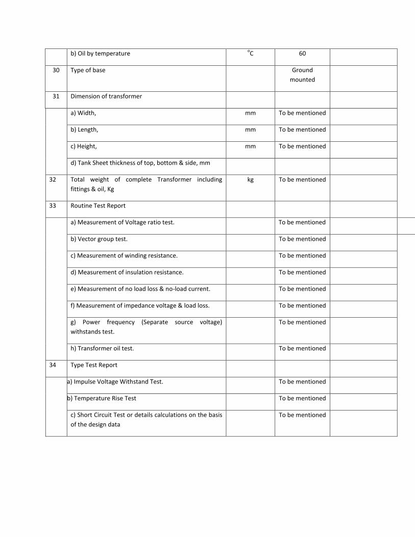
b) Oil by temperature oC 60
30 Type of base Ground
mounted
31 Dimension of transformer
a) Width, mm To be mentioned
b) Length, mm To be mentioned
c) Height, mm To be mentioned
d) Tank Sheet thickness of top, bottom & side, mm
32 Total weight of complete Transformer including
fittings & oil, Kg
kg To be mentioned
33 Routine Test Report
a) Measurement of Voltage ratio test. To be mentioned
b) Vector group test. To be mentioned
c) Measurement of winding resistance. To be mentioned
d) Measurement of insulation resistance. To be mentioned
e) Measurement of no load loss & no-load current. To be mentioned
f) Measurement of impedance voltage & load loss. To be mentioned
g) Power frequency (Separate source voltage)
withstands test.
To be mentioned
h) Transformer oil test. To be mentioned
34 Type Test Report
a) Impulse Voltage Withstand Test. To be mentioned
b) Temperature Rise Test To be mentioned
c) Short Circuit Test or details calculations on the basis
of the design data
To be mentioned

7. 33KV BUSBARS AND CONNECTIONS
Sl.
No.
Description Unit Requirement Manufacturer’s
Guaranteed Data
A. CONDUCTORS AND CONNECTIONS
1. Manufacturer To be mentioned
2. Material of conductor To be mentioned
a) Bus-bar ACSR/2xMartin
b) Jumper/connections To be mentioned
3. Overall diameter mm To be mentioned
4. Nominal cross section mm2 To be mentioned
5. Maximum rated current A 2500
6. Maximum working tension of main connections kg/m2 To be mentioned
7. DC resistance of conductors per 1000 meters at 20ºC Ohms To be mentioned
8. Tensile breaking stress of material N/mm2 To be mentioned
9. Maximum permissible span length m To be mentioned
10. Maximum sag under own weight of maximum span mm To be mentioned
11. Temperature rise at rated current ºC 35
8. 33KV BUSBAR INSULATOR STRINGS
B. INSULATORS
1 Manufacturer - To be mentioned
2 Model no. - To be mentioned
3 Insulator material - Porcelain
4 Number of units per string Nos. 4
5 Insulator Voltage Class KV

6. Weight of insulator complete kg
7 Type of Insulator - Ball and socket
type disc, security
clip made of rod
brass alloy.
8 Creepage/ leakage distance (min.) mm To be mentioned
9 Total creepage distance of string mm 900
10 Unit Spacing mm To be mentioned
11 Dry Arcing distance (minimum) mm To be mentioned
12 Diameter of Insulator mm To be mentioned
13 Withstand Voltage, Minimum :
a) Power Frequency, dry (one min.) KV 70
b) Power Frequency, wet (one min.) KV 40
c) Impulse 1.2/50 sec KV 110
14 Flashover Voltage, Minimum :
a) Power Frequency, dry KV 80
b) Power Frequency, wet KV 50
c) 50% Impulse 1.2/50 sec wave, positive or impulse
1.2/50 sec wave positive.
KV 125
d) 50% Impulse 1.2/50 sec wave Negative KV 130
15 Power Frequency Puncture Voltage, minimum KV 110
16 Minimum Mechanical Strength for Suspension :
a) Electro-mechanical Breaking Load Kg 7260
b) Mechanical Breaking load Kg 6800
c) Tension Proof Test Load Kg 3400
d) Time Load Test Value Kg 4536
e) Mechanical Impact Strength mm Kg 630

17 Minimum Mechanical Strength for Strain Stringing :
a) Electro-mechanical Breaking Load Kg 11340
b) Mechanical Breaking load Kg 11340
c) Tension Proof Test Load Kg 3400
d) Time Load Test Value Kg 4536
e) Mechanical Impact Strength mm Kg 530
18 Insulator Hardware Insulator
hardware for
insulator strings
or bus-support
such shall have
UTS-120 KN and
galvanized as per
BS-729.
19 Standard AS per latest
editions of IEC-
383.
9. SHIELD WIRES, EARTHING GRID AND EARTHING ELECTRODE
A SHIELD WIRES
Sl.
No.
Description Unit Requirement Manufacturer’s
Guaranteed Data
1 Manufacturer To be mentioned
2 Conductor material High strength
steel
3 Grade of steel PSI 60000
4 Nos. of strand Nos 7
5 Diameter of each strand mm 3.25
6 Overall diameter mm 9.80
7 Nominal cross section mm2 35
8 Weight per 1000 meter length kg 460
9 Maximum rated current (3 sec) A To be mentioned
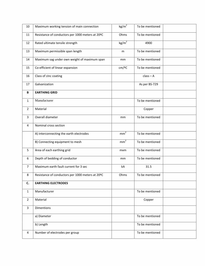
10 Maximum working tension of main connection kg/m2 To be mentioned
11 Resistance of conductors per 1000 meters at 20ºC Ohms To be mentioned
12 Rated ultimate tensile strength kg/m2 4900
13 Maximum permissible span length m To be mentioned
14 Maximum sag under own weight of maximum span mm To be mentioned
15 Co-efficient of linear expansion cm/ºC To be mentioned
16 Class of zinc coating class – A
17 Galvanization As per BS-729
B EARTHING GRID
1 Manufacturer To be mentioned
2 Material Copper
3 Overall diameter mm To be mentioned
4 Nominal cross section
A) interconnecting the earth electrodes mm2 To be mentioned
B) Connecting equipment to mesh mm2 To be mentioned
5 Area of each earthing grid mxm To be mentioned
6 Depth of bedding of conductor mm To be mentioned
7 Maximum earth fault current for 3 sec kA 31.5
8 Resistance of conductors per 1000 meters at 20ºC Ohms To be mentioned
C. EARTHING ELECTRODES
1 Manufacturer To be mentioned
2 Material Copper
3 Dimentions
a) Diameter To be mentioned
b) Length To be mentioned
4 Number of electrodes per group To be mentioned

5 Number of earthing points To be mentioned
6 Caculated resistance of combined earth grid and
points
Ohm Less than 0.5
10. BATTERIY AND CHARGER CUBICLE
Sl.
No.
Description Unit Requirement Manufacturer’s
Guaranteed Data
A. BATTERY
1 Manufacturer To be mentioned
2 Model no To be mentioned
3 Electrolyte Nickel Cadmium
Alkaline
4 Installation Indoor
5 Operating voltage V DC 110
6 Continuous Discharge Current at rate of 10 hour &
Final Cell Voltage 1.1 Volt.
Amp 10
7 Short Time Discharge Current at rate of 2 hour & Final
Cell Voltage 1.1 Volt.
Amp 50
8 Charging Voltage (Maximum) Volt 1.54-1.69 Per Cell
9 Normal float charge rate A To be mentioned
10 Maximum boost charge rate A To be mentioned
11 Voltage per cell V/per cell 1.2
12 Capacity at 5 hour rate Ah 250
13 Number of cells Nos 92
14 Float voltage per cell V per cell 1.4-1.42
Discharge voltage v per cell 1.3-1.5
15 Battery voltage at end of the duty cycle V 1.1V per cell

16 Nominal charging rate A 40
17 Maximum charging rate A 40
18 Ampere-hour efficiency at ten hour rate % To be mentioned
19 Ampere-hour efficiency at one hour rate % To be mentioned
20 Dimensions of cells mm To be mentioned
22 Weight of cell complete with electrolyte kg To be mentioned
23 Internal resistance per cell when fully charged ohms To be mentioned
24 Material of battery case To be mentioned
25 Standard IEC 623
B. CHARGER
1 Manufacturer To be mentioned
2 Model no To be mentioned
3 Rectifier Type Thyristor
4 AC input voltage V 415V15%
5 Input a.c frequency HZ 505%
6 DC output voltage
a) Normal Charge V DC 11010%
b) Float Charge V DC 1.42 for11015%
c) Boost Charge V DC 1.53 volt per cell
7 Output current (continuous) A 50
8 Rated Battery Current A To be mentioned
9 Efficiency % To be mentioned
10 Ripple Voltage % To be mentioned
11 Type of AVR Static
12 Standard % IEC-146
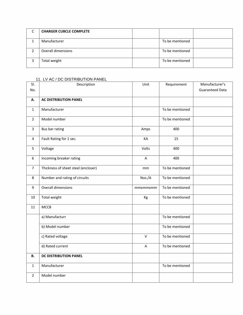
C CHARGER CUBCLE COMPLETE
1 Manufacturer To be mentioned
2 Overall dimensions To be mentioned
3 Total weight To be mentioned
11. LV AC / DC DISTRIBUTION PANEL
Sl.
No.
Description Unit Requirement Manufacturer’s
Guaranteed Data
A. AC DISTRIBUTION PANEL
1 Manufacturer To be mentioned
2 Model number To be mentioned
3 Bus bar rating Amps 400
4 Fault Rating for 1 sec. KA 15
5 Voltage Volts 400
6 Incoming breaker rating A 400
7 Thickness of sheet steel (encloser) mm To be mentioned
8 Number and rating of circuits Nos./A To be mentioned
9 Overall dimensions mmxmmxmm To be mentioned
10 Total weight Kg To be mentioned
11 MCCB
a) Manufacturr To be mentioned
b) Model number To be mentioned
c) Rated voltage V To be mentioned
d) Rated current A To be mentioned
B. DC DISTRIBUTION PANEL
1 Manufacturer To be mentioned
2 Model number

3 Bus bar rating Amps 40
4 Fault Rating for 1 sec KA 6
5 Voltage Volts 400
6 Incoming breaker rating A 400
7 Thickness of sheet steel (encloser) mm To be mentioned
8 Number and rating of circuits Nos./A To be mentioned
9 Overall dimensions mmxmmxmm To be mentioned
10 Total weight Kg To be mentioned
11 MCCB
a) Manufacturr To be mentioned
b) Model number To be mentioned
c) Rated voltage V To be mentioned
d) Rated current A To be mentioned
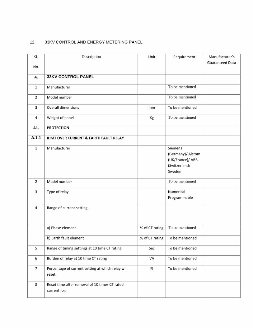
12. 33KV CONTROL AND ENERGY METERING PANEL
Sl.
No.
Description Unit Requirement Manufacturer’s
Guaranteed Data
A. 33KV CONTROL PANEL
1 Manufacturer To be mentioned
2 Model number To be mentioned
3 Overall dimensions mm To be mentioned
4 Weight of panel Kg To be mentioned
A1. PROTECTION
A.1.1 IDMT OVER CURRENT & EARTH FAULT RELAY
1 Manufacturer Siemens
(Germany)/ Alstom
(UK/France)/ ABB
(Switzerland/
Sweden
2 Model number To be mentioned
3 Type of relay Numerical
Programmable
4 Range of current setting
a) Phase element % of CT rating To be mentioned
b) Earth fault element % of CT rating To be mentioned
5 Range of timing settings at 10 time CT rating Sec To be mentioned
6 Burden of relay at 10 time CT rating VA To be mentioned
7 Percentage of current setting at which relay will
reset
% To be mentioned
8 Reset time after removal of 10 times CT rated
current for:

a) Phase element (100%) Sec To be mentioned
b) E/F element (40%) Sec To be mentioned
A2. METERING AND INDICATION
A.2.1 KWH METER Separate Panel for
Energy Metering
1 Manufacturer Siemens(Germany/
Switzerland)/Alsto
m,(UK)/ABB(Switze
rland)/AEG(Germa
ny)/Schlumberger
(USA)
2 Model number To be mentioned
3 Type of Meter Numerical
Programmable
multifunction
4 Number of KWH Meters 2 with provision of
4 meters in a
separate metering
panel
5 Class of accuracy 0.2
A2.2 INDICATION METERS (VOLT, AMPERE, KW, KVAR &
POWER FACTOR)
1 Manufacturer Siemens(Germany/
Switzerland)/Alsto
m,(UK)/ABB(Switze
rland)/AEG(Germa
ny)/Schlumberger(
USA)
2 Model number To be mentioned
3 Type of Meter Digital/Analog
4 Class of accuracy To be mentioned

13. STEEL STRUCTURE
Sl.
No.
Description Unit Requirement Manufacturer’s
Guaranteed Data
1 Manufacturer - To be mentioned
2 Maximum ratio of unsupported length of steel compression to
their least redius of gyration:
a) Main members mm 120
b) Bracing's mm 200
c) Redundant mm 250
3 Steel Grade Mild Steel
a) Elastic limit stress in tension members Kg/
mm2
To be mentioned
b) Ultimate stress in compression members
(expressed as function L/R)
Kg/
mm2
To be mentioned
4 Steel Grade HTGH Tension Steel
a) Elastic limit stress in tension members Kg/
mm2
To be mentioned
b) Ultimate stress in compression members (expressed as
function L/R)
Kg/
mm2
To be mentioned
5 Minimum size of member mm 45 x 45 x 6
6 Weight of each Column Kg To be mentioned
7 Weight of each Girder Kg To be mentioned
8 Total weight Kg To be mentioned
9 Minimum member thickness mm 6
Main member mm 5
Other breching member mm 5
Bolt diameter mm 16
10 Galvanizing thickness mm 85

14. Control cable
PVC insulated multi core control cable Laid up beded with PVC or tap. Flat / round wire armoring with helical steel
taping and PVC sheathed, rated voltage 600/1000, continuous permissible voltage 720/1200 volts (VDE 0271/3.69
BDS 901: 85) (NYRGby) suitable for use in indoors, outdoors, underground and in water for continuous
permissible service voltage of 720/1200 volts. Maximum resistance 4.73 ohm/km at 35°C.
a) Guaranteed Technical Particulars for 4C4 mm2 XLPE Insulated and PE Sheathed Copper Cable
(To be filled u by the Manufacturer in Manufacturer’s Letterhead Pad with appropriated data)
Sl
No.
Description Unit Purchaser’s Requirement Manufacturer’s
Particulars
1 Name of the Item 4c4 mm2LPE Insulated
and PE Sheathed Copper
Cable with Armouring
2 Name of the Manufacturer Shall be mentioned
3 Address of the Manufacturer Shall be mentioned
4 Standard Performance Design and
Testing shall be in
accordance to the BS,
IEC, BDS or equivalent
International Standards.
5 Cable Size mm2 4C4 rm
6 Material XLPE Insulated and PE
Sheathed Copper Cable
with Armouring
7 Numbers & Diameter of Copper Wires mm 7/0.85
8 Numbers & Diameter of Steel Wires mm 24/1.4
9 Nominal size of Steel Tape mm 80.3
10 Maximum resistance at 30 deg.c Ω/Km 4.56
11 Nominal thickness of insulation mm 0.8 (min)
12 Nominal thickness of sheath mm 1.8 (min)
13 Colour of sheath Black
14 Colour of Core Red, Yellow, Blue, Black
15 Approximate outer diameter mm 19
16 Approximate weight Kg/Km 760
17 Drum wound length m 1000
18 Net Weight Kg Shall be mentioned
19 Gross weight Kg Shall be mentioned
20 Treated Wooden Drum Standard AWPA C1-82,
C2-83, c16-82,
P5-83.

b) Guaranteed Technical Particulars for 4C6 mm2 XLPE Insulated and PE Sheathed Copper Cable
(To be filled u by the Manufacturer in Manufacturer’s Letterhead Pad with appropriated data)
Sl
No.
Description Unit Purchaser’s Requirement Manufacturer’s
Particulars
1 Name of the Item To be mentioned
2 Name of the Manufacturer To be mentioned
3 Address of the Manufacturer To be mentioned
4 Standard To be mentioned
5 Cable Size mm2 4C6 rm
6 Material To be mentioned
7 Numbers & Diameter of Copper Wires mm To be mentioned
8 Numbers & Diameter of Steel Wires mm To be mentioned
9 Nominal size of Steel Tape mm To be mentioned
10 Maximum resistance at 30 deg.c Ω/Km To be mentioned
11 Nominal thickness of insulation mm To be mentioned
12 Nominal thickness of sheath mm To be mentioned
13 Colour of sheath To be mentioned
14 Colour of Core To be mentioned
15 Approximate outer diameter mm To be mentioned
16 Approximate weight Kg/Km To be mentioned
17 Drum wound length m To be mentioned
18 Net Weight Kg To be mentioned
19 Gross weight Kg To be mentioned
20 Treated Wooden Drum Standard To be mentioned
c) Guaranteed Technical Particulars for 2C4 mm2 XLPE Insulated and PE Sheathed Copper Cable
(To be filled u by the Manufacturer in Manufacturer’s Letterhead Pad with appropriated data)
Sl
No.
Description Unit Purchaser’s Requirement Manufacturer’s
Particulars
1 Name of the Item To be mentioned
2 Name of the Manufacturer To be mentioned
3 Address of the Manufacturer To be mentioned
4 Standard To be mentioned
5 Cable Size mm2 2C4 rm
6 Material To be mentioned
7 Numbers & Diameter of Copper Wires mm To be mentioned
8 Numbers & Diameter of Steel Wires mm To be mentioned
9 Nominal size of Steel Tape mm To be mentioned
10 Maximum resistance at 30 deg.c Ω/Km To be mentioned
11 Nominal thickness of insulation mm To be mentioned

12 Nominal thickness of sheath mm To be mentioned
13 Colour of sheath To be mentioned
14 Colour of Core To be mentioned
15 Approximate outer diameter mm To be mentioned
16 Approximate weight Kg/Km To be mentioned
17 Drum wound length m To be mentioned
18 Net Weight Kg To be mentioned
19 Gross weight Kg To be mentioned
20 Treated Wooden Drum Standard To be mentioned
d) Guaranteed Technical Particulars for 2C6 mm2 XLPE Insulated and PE Sheathed Copper Cable
(To be filled u by the Manufacturer in Manufacturer’s Letterhead Pad with appropriated data)
Sl
No.
Description Unit Purchaser’s Requirement Manufacturer’s
Particulars
1 Name of the Item To be mentioned
2 Name of the Manufacturer To be mentioned
3 Address of the Manufacturer To be mentioned
4 Standard To be mentioned
5 Cable Size mm2 2C6 rm
6 Material To be mentioned
7 Numbers & Diameter of Copper Wires mm To be mentioned
8 Numbers & Diameter of Steel Wires mm To be mentioned
9 Nominal size of Steel Tape mm To be mentioned
10 Maximum resistance at 30 deg.c Ω/Km To be mentioned
11 Nominal thickness of insulation mm To be mentioned
12 Nominal thickness of sheath mm To be mentioned
13 Colour of sheath To be mentioned
14 Colour of Core To be mentioned
15 Approximate outer diameter mm To be mentioned
16 Approximate weight Kg/Km To be mentioned
17 Drum wound length m To be mentioned
18 Net Weight Kg To be mentioned
19 Gross weight Kg To be mentioned
20 Treated Wooden Drum Standard To be mentioned
e) Guaranteed Technical Particulars for 19C4 mm2 XLPE Insulated and PE Sheathed Copper Cable
(To be filled u by the Manufacturer in Manufacturer’s Letterhead Pad with appropriated data)
Sl
No.
Description Unit Purchaser’s Requirement Manufacturer’s
Particulars
1 Name of the Item To be mentioned
2 Name of the Manufacturer To be mentioned
3 Address of the Manufacturer To be mentioned
4 Standard To be mentioned
5 Cable Size mm2 19C4 rm

6 Material To be mentioned
7 Numbers & Diameter of Copper Wires mm To be mentioned
8 Numbers & Diameter of Steel Wires mm To be mentioned
9 Nominal size of Steel Tape mm To be mentioned
10 Maximum resistance at 30 deg.c Ω/Km To be mentioned
11 Nominal thickness of insulation mm To be mentioned
12 Nominal thickness of sheath mm To be mentioned
13 Colour of sheath To be mentioned
14 Colour of Core To be mentioned
15 Approximate outer diameter mm To be mentioned
16 Approximate weight Kg/Km To be mentioned
17 Drum wound length m To be mentioned
18 Net Weight Kg To be mentioned
19 Gross weight Kg To be mentioned
20 Treated Wooden Drum Standard To be mentioned
15. POWER CABLES
15.1. 33 KV POWER CABLES (U/G)
Guaranteed Technical Data Schedule of 33KV, 1-Core × 500 Sq.mm U/G XLPE Copper Cable
SL
No.
Description Unit Required
Specification
Manufacturer’s
Particulars
1 Name and address of the
Manufacturer
To be mentioned
2 Type/Model of the offered cable To be mentioned
3 Nominal system voltage KV 33
4
Rated voltage of cable KV 18/30(36)
5 Process of manufacturing VCV/CCV
6 Number of core and cross
sectional area of conductor cores
Sq.mm 1×500
7 Conductor material Copper
8 Minimum no of strand No. 53

9 Diameter of each strand mm To be mentioned
10 Shape of conductor Compacted Circular
11 Type of conductor screen Semi-conducting
12 Thickness of semi conducting
screen
mm 0.6
13 Avg. thickness of insulation mm 8.0
14 Process of curing Dry process
15 Material of insulation Cross Linked
Polyethylene (XLPE)
16 Type of non metallic insulating
screen
Semi-conducting
17 Thickness of semi conducting
insulation screen
mm 1.0
18 Number and diameter of copper
screen strands
No./mm Based on design
calculation
19 Composition of filler PVC
20 Composition of bedding Extruded PVC
21 Thickness of bedding mm Based on design
calculation
22 Number and diameter of armour
wire
No./mm As per IEC 60502
23 Avg. thickness of MDPE over
sheath
mm Based on design
calculation
24 Nominal diameter of complete
cable
mm Based on design
calculation
25 Nominal weight per meter of
complete cable
Kg/m Based on design
calculation
26 Minimum radius of bend round
which cable can be laid
mm Based on design
calculation
27 Max. D.C resistance of conductor
per meter at 20 C
Ohm/m Based on design
calculation

28 Max. A.C resistance of conductor
per meter at MAXIMUM
CONDUCTOR TEMPARATURE
Ohm/m Based on design
calculation
29 Star resistance per meter of cable
at 50Hz
Ohm/m Based on design
calculation
30 Star capacitance per per meter of
cable at 50Hz
pF/m Based on design
calculation
31 Charging current per conductor
per meter at 18000/30000 Volts ,
50Hz
mA Based on design
calculation
32 Maximum current carrying
capacity of conductor in ground
A Based on design
calculation
33 Maximum conductor temperature
under continuous loading
C Based on design
calculation
34 Short circuit withstand capacity
nof the cable for 1 sec. duration
KA Min. 25
35 conductor temperature at the end
of short circuit
C ≤250
36 Earth fault withstand capacity for 1 sec.
KA Min. 25
37
Screen short circuit withstand capacity
KA Min. 25
38 Armour short circuit capacity KA Based on design calculation
39
Cable resistance, reactance
a) for positive sequence Ohm/m Based on design calculation
b) negative sequence Ohm/m Based on design calculation
c) Zero sequence Ohm/m Based on design calculation

BANGLADESH RURAL ELECTRIFICATION BOARD
TENDER DOCUMENT
FOR
TURNKEY CONTRACT FOR DESIGN, SUPPLY, CONSTRUCTION, INSTALLATION, TESTING & COMMISSIONING
WORK FOR EXTENSION OF 33KV NEW BAY AT 132/33 KV ISHWARDI GRID SUB-STATION FOR PABNA PBS- 1
UNDER BREB
SCHEDULE F
DEPARTURES FROM SPECIFICATIONS

BANGLADESH RURAL ELECTRIFICATION BOARD
TURNKEY CONTRACT FOR DESIGN, SUPPLY, CONSTRUCTION, INSTALLATION, TESTING & COMMISSIONING
WORK FOR EXTENSION OF 33KV NEW BAY AT 132/33 KV ISHWARDI GRID SUB-STATION FOR PABNA PBS- 1
UNDER BREB.
SCHEDULE F
DEPARTURES FROM SPECIFICATIONS
Tenderers are to list all departures from the requirements of the specification in this schedule. All departures
whether they be commercial, financial, technical or of a contractual nature are to be included and submitted with
the Technical Proposal.
Any item that does not have a departure listed in this schedule will be deemed to be in full accordance with the
requirements of the specification.
No other document or detail accompanying the tender will be considered in evaluating departures. Tenderers are
not permitted to offer any alternative to this schedule.
Item Volume Clause Detail of Departure from Specification

BANGLADESH RURAL ELECTRIFICATION BOARD
TENDER DOCUMENT
FOR
TURNKEY CONTRACT FOR DESIGN, SUPPLY, CONSTRUCTION, INSTALLATION, TESTING & COMMISSIONING
WORK FOR EXTENSION OF 33KV NEW BAY AT 132/33 KV ISHWARDI GRID SUB-STATION FOR PABNA PBS- 1
UNDER BREB.
SCHEDULE G
PROPOSED ALTERNATIVE STANDARDS TO WHICH EQUIPMENT SHALL BE
PROVIDED
BANGLADESH RURAL ELECTRIFICATION BOARD
TURNKEY CONTRACT FOR DESIGN, SUPPLY, CONSTRUCTION, INSTALLATION, TESTING & COMMISSIONING
WORK FOR EXTENSION OF 33KV NEW BAY AT 132/33 KV ISHWARDI GRID SUB-STATION FOR PABNA PBS- 1
UNDER BREB.
SCHEDULE G
PROPOSED ALTERNATIVE STANDARDS TO WHICH EQUIPMENT SHALL BE PROVIDED
The Tenderer shall list below all the alternative engineering and design Standards, which he proposes to use in his
design, manufacture and testing of equipment to be supplied. Should these standards differ from the specified
standard in any respect, the Tenderer shall detail the differences between the proposed and specified standard.
Compliance with any standard equal or superior to those specified will be considered acceptable.
In the absence of any listed alternative standard, it is deemed that the standards specified in the Tender
Documents are fully complied with.

BANGLADESH RURAL ELECTRIFICATION BOARD
TENDER DOCUMENT
FOR
TURNKEY CONTRACT FOR DESIGN, SUPPLY, CONSTRUCTION, INSTALLATION, TESTING & COMMISSIONING
WORK FOR EXTENSION OF 33KV NEW BAY AT 132/33 KV ISHWARDI GRID SUB-STATION FOR PABNA PBS- 1
UNDER BREB.
SCHEDULE H
PROPOSED CONTRACT AND SITE ORGANISATION AND SITE RESOURCES

BANGLADESH RURAL ELECTRIFICATION BOARD
TURNKEY CONTRACT FOR DESIGN, SUPPLY, CONSTRUCTION, INSTALLATION, TESTING & COMMISSIONING
WORK FOR EXTENSION OF 33KV NEW BAY AT 132/33 KV ISHWARDI GRID SUB-STATION FOR PABNA PBS- 1
UNDER BREB.
SCHEDULE H
PROPOSED CONTRACT AND SITE ORGANISATION AND SITE RESOURCES
The Tenderer is required to provide full organization charts of his proposed head office and site office arrangements. This should include how site subcontractors are to interface with the contractor’s organization.
The Tenderer shall list in the form of Schedule attached, the key personnel (including first nominee and the
second choice alternate)he will employ at head office and site office to direct and execute and work for the
execution of the Contract together with their qualifications, positions held and their nationalities. Should
specialist sub-designers be proposed (e.g civil designers) details of these are also to be provided with how this
interface with the contractor’s organization.
Should the Tenderer be proposing to put any restriction on his site managers authority to carry out the
instructions issued by the Employer Representative, full details of these, be they financial/contractual/technical
are to be provided in the tender.
The information provided in the Tender in accordance with the above, will not represent any limitations on the
staff required to perform the works in accordance with the conditions of Contract. Should the Contractor require
utilizing additional staff to those proposed in order to meet his obligations these are to be provided at no
additional cost. The Contractor shall however have to employ all the expatriate staffs proposed in the tender as
to be employed at site. In case of failure to employ the expatriate staffs at site as per tender proposal, the
Employer may go for termination of the Contract.

In addition the Tenderer is required to provide a schedule of the site resources he intends to provide, e.g.
equipment for haulage, lifting, site power supplies, foundation, erection, stringing, testing and commissioning.
Major items of equipment for construction purposes, which the Tenderer proposes to import, are to be
submitted with the Tender. The Tenderer shall have to bring the above proposed equipment during construction
otherwise they may be panelized, as per clause of the tender, for any delay due to non-availability of such
equipment at site. The successful Tenderer will be required to submit detailed schedules of his proposed site
testing and commissioning equipment and experience of his commissioning engineers.
The Tenderer is also required to provide details of his site organization concerning office locations, storage
facilities proposed, both open and covered, site transportation, etc. The successful Tenderer will be required to
provide details of his proposed organizational procedures for the receipt, inspection and transportation of plant,
plus monthly progress monitoring, invoice submission etc.
The Contractor shall ensure that the cash flow is maintained as forecasted in their price proposal. In case there is
any liquidity problem for which there is any delay in implementing the project, the Contractor may be panelized
as per tender.

SCHEDULE H OF KEY PERSONNEL
Position Name Nationality Summary of qualifications,
experience and present occupation
Head Office Staff:
Site Office Staff:
Signature and Seal of the Tenderer

SCHEDULE H OF EQUIPMENT FOR CONSTRUCTION
Name of Equipment Ownership Present Location
Signature and Seal of the Tenderer

BANGLADESH RURAL ELECTRIFICATION BOARD
TENDER DOCUMENT
FOR
TURNKEY CONTRACT FOR DESIGN, SUPPLY, CONSTRUCTION, INSTALLATION, TESTING &
COMMISSIONING WORK FOR EXTENSION OF 33KV NEW BAY AT 132/33 KV ISHWARDI GRID SUB-
STATION FOR PABNA PBS- 1 UNDER BREB.
SCHEDULE I
DRAWINGS AND DOCUMENTS TO BE SUBMITTED
WITH TENDER

BANGLADESH RURAL ELECTRIFICATION BOARD
TURNKEY CONTRACT FOR DESIGN, SUPPLY, CONSTRUCTION, INSTALLATION, TESTING & COMMISSIONING
WORK FOR EXTENSION OF 33KV NEW BAY AT 132/33 KV ISHWARDI GRID SUB-STATION FOR PABNA PBS- 1
UNDER BREB.
SCHEDULE I
DRAWINGS AND DOCUMENTS TO BE SUBMITTED WITH TENDER
FOR 33 KV SWITCHING STATION WORK
The Tenderer shall submit the following drawings/documents with the tender:
1. Typical plan and section drawings of transformer incoming, bus coupler and outgoing feeders for 33 kV
switchyard.

2. Block diagram showing overall dimensions of 33kV switchyard at site.
3. Drawings of circuit breakers, disconnecting switches, current transformers, voltage transformers,
lightning arresters and disc Insulator units showing details of construction and dimensions.
4. Typical arrangement drawing of control panel cubicles, energy meter panel cubicle, battery charger
cubicle, LVAC and DC distribution boards.
5. Typical block-schematic and logic diagrams of all protection and control schemes.
6. Lay-out Plan of control panel to be installed in substation control room building.
7. Cross Section Drawing of the head design of the insulator unit.
8. Type test certificate of the following shall be submitted as per relevant IEC/BS standards.
i) Circuit Breaker (VCB)
(a) Lightning impulse voltage withstand dry test
(b) Temperature rise test (c) Power frequency withstand test (d) Short time withstand & Peak withstand current test (e) Mechanical operation tests (f) Short Circuit Current making & breaking test (g) Out of phase making & breaking test
ii) Disconnecting Switch DS/ES)
(a) Lightning Impulse voltage withstand dry test (b) Power frequency voltage withstand dry test (c) Short time withstand current test
iii) Current Transformer (CT)
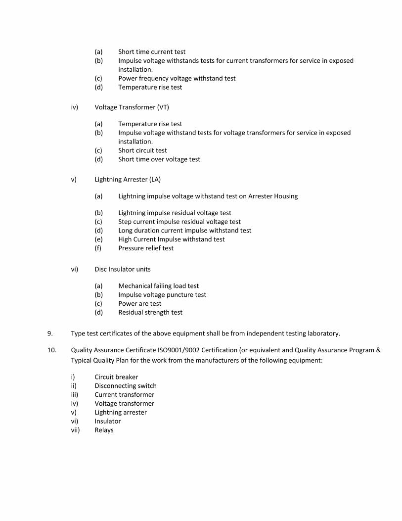
(a) Short time current test (b) Impulse voltage withstands tests for current transformers for service in exposed
installation. (c) Power frequency voltage withstand test (d) Temperature rise test
iv) Voltage Transformer (VT)
(a) Temperature rise test (b) Impulse voltage withstand tests for voltage transformers for service in exposed
installation. (c) Short circuit test (d) Short time over voltage test
v) Lightning Arrester (LA)
(a) Lightning impulse voltage withstand test on Arrester Housing
(b) Lightning impulse residual voltage test (c) Step current impulse residual voltage test (d) Long duration current impulse withstand test (e) High Current Impulse withstand test (f) Pressure relief test
vi) Disc Insulator units
(a) Mechanical failing load test (b) Impulse voltage puncture test (c) Power are test (d) Residual strength test
9. Type test certificates of the above equipment shall be from independent testing laboratory.
10. Quality Assurance Certificate ISO9001/9002 Certification (or equivalent and Quality Assurance Program &
Typical Quality Plan for the work from the manufacturers of the following equipment:
i) Circuit breaker ii) Disconnecting switch iii) Current transformer iv) Voltage transformer v) Lightning arrester vi) Insulator vii) Relays

DRAWINGS AND DOCUMENTS TO BE SUBMITTED WITH TENDER
FOR 33 KV LINE AUGMENTATION WORK
1. According to design & drawing, Technical Specification and GTP of all materials to be used for
augmentation of 33 kV existing line.
2. Relevant all Test Report of all materials to be used for augmentation of 33 kV existing line confirming
the Technical Specification and GTP submitted by the Tenderer.
3. Manufacturer’s Assurance Certificate for supplying line materials in favour of the Tender.
4. Quality Assurance Certificate ISO9001/9002 Certification (or equivalent and Quality Assurance Program
& Typical Quality Plan for the work from the manufacturers of the required materials for 33 kV line
augmentation work.
5. Brochure/Catalog of manufacturer indicating manufacturing facilities and available materials.
BANGLADESH RURAL ELECTRIFICATION BOARD
TENDER DOCUMENT
FOR
TURNKEY CONTRACT FOR DESIGN, SUPPLY, CONSTRUCTION, INSTALLATION, TESTING & COMMISSIONING
WORK FOR EXTENSION OF 33KV NEW BAY AT 132/33 KV ISHWARDI GRID SUB-STATION FOR PABNA PBS- 1
UNDER BREB.
SCHEDULE J
PROPOSED SUBCONTRACTORS

BANGLADESH RURAL ELECTRIFICATION BOARD
TURNKEY CONTRACT FOR DESIGN, SUPPLY, CONSTRUCTION, INSTALLATION, TESTING &
COMMISSIONING WORK FOR EXTENSION OF 33KV NEW BAY AT 132/33 KV ISHWARDI
GRID SUB-STATION FOR PABNA PBS- 1 UNDER BREB.
SCHEDULE J
PROPOSED SUBCONTRACTORS
The Tenderer shall propose a list of the subcontractors in the following table as per sub-clause 4.5 Subcontractors, Part – II, Conditions of Particular Application of Volume 1 of 3.
Sl. No. Name and Address of the Subcontractors

Signature--------------------------------------
Date--------------------------------------------

BANGLADESH RURAL ELECTRIFICATION BOARD
TENDER DOCUMENT
FOR
TURNKEY CONTRACT FOR DESIGN, SUPPLY, CONSTRUCTION, INSTALLATION, TESTING &
COMMISSIONING WORK FOR EXTENSION OF 33KV NEW BAY AT 132/33 KV ISHWARDI GRID SUB-
STATION FOR PABNA PBS- 1 UNDER BREB.
DRAWINGS FORMING PART OF SPECIFICATIONS
BANGLADESH RURAL ELECTRIFICATION BOARD
TENDER DOCUMENT
FOR
TURNKEY CONTRACT FOR DESIGN, SUPPLY, CONSTRUCTION, INSTALLATION, TESTING & COMMISSIONING
WORK FOR EXTENSION OF 33KV NEW BAY AT 132/33 KV ISHWARDI GRID SUB-STATION FOR PABNA PBS- 1
UNDER BREB.
SCHEDULE K
MANUFACTURER’S AUTHORIZATION LETTER

BANGLADESH RURAL ELECTRIFICATION BOARD
TURNKEY CONTRACT FOR DESIGN, SUPPLY, CONSTRUCTION, INSTALLATION, TESTING & COMMISSIONING
WORK FOR EXTENSION OF 33KV NEW BAY AT 132/33 KV ISHWARDI GRID SUB-STATION FOR PABNA PBS- 1
UNDER BREB.
SCHEDULE K
Manufacturer’s Authorization Letter
[This letter of authorization should be on the letterhead of the manufacturer and should be signed by the person
with the proper authority to sign documents that are binding on the manufacturer]
Invitation for Tender No: Date:
Tender Identification No:
To:
(Name and address of The Employer)
WHEREAS, we [name and address of manufacturer] are reputable manufacturers having factories at [list of places
of factories].
Therefore, we do hereby:

1. Authorize [name of Tenderer] to submit a Tender in response to the invitation for Tenders indicated above, the purpose of which is to provide the [description of goods], manufactured by us, and to subsequently sign the Contract for the supply of such Goods; and,
2. Extend our full guarantee and warranty in accordance with GCC Clause 10 with respect to the Goods offered in the Tender.
Signed
In the capacity of:
Duly authorized to sign the authorization for and on behalf of
[ Name of manufacturer]
Date:

BANGLADESH RURAL ELECTRIFICATION BOARD (BREB)
TENDER DOCUMENT
FOR THE
TURNKEY CONTRACT FOR DESIGN, SUPPLY, CONSTRUCTION, INSTALLATION, TESTING &
COMMISSIONING WORK FOR EXTENSION OF 33KV NEW BAY AT 132/33 KV ISHWARDI
GRID SUB-STATION FOR PABNA PBS- 1 UNDER BREB.
VOLUME 3 OF 3
SECTION:9- DRAWINGS