Embed Size (px)
Citation preview

SAVE THESE INSTRUCTIONS
3-Pt. Rotary Tiller
Owner’s Manual
WARNING: Read carefully and understand all ASSEMBLY AND OPERATION
INSTRUCTIONS before operating. Failure to follow the safety rules and other basic safety
precautions may result in serious personal injury.
Item #51460
Page 2 of 28
Thank you very much for choosing a Nortrac™
product!
For future reference, please complete the owner’s record below:
Serial Number/Lot Date Code: ________________________________
Purchase Date: ____________________________________________
Save the receipt, warranty, and this manual. It is important that you read
the entire manual to become familiar with this product before you begin
using it.
This 3-Pt. Rotary Tiller is designed for certain applications only. Northern
Tool & Equipment is not responsible for issues arising from modification
or improper use of this product such as an application for which it was
not designed. We strongly recommend that this product not be modified
and/or used for any application other than that for which it was designed.
For technical questions, please call 1-800-222-5381.

Page 3 of 28
Table of Contents
Intended Use .......................................................................................................................................... 4
Technical Specifications ...................................................................................................................... 4
Important Safety Information ............................................................................................................... 5
Specific Operation Warnings ............................................................................................................... 6
Assembly Instructions .......................................................................................................................... 8
Before Each Use .................................................................................................................................. 16
Operating Instructions ........................................................................................................................ 17
Maintenance ........................................................................................................................................ 19
Troubleshooting .................................................................................................................................. 20
Replacement Parts .............................................................................................................................. 26
Limited Warranty ................................................................................................................................. 27
Page 4 of 28
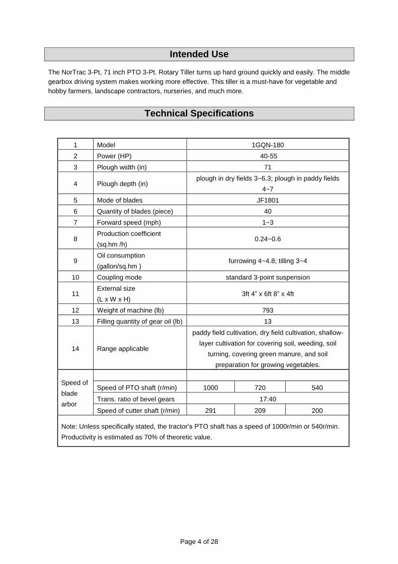
Intended Use
The NorTrac 3-Pt, 71 inch PTO 3-Pt. Rotary Tiller turns up hard ground quickly and easily. The middle
gearbox driving system makes working more effective. This tiller is a must-have for vegetable and
hobby farmers, landscape contractors, nurseries, and much more.
Technical Specifications
1 Model 1GQN-180
2 Power (HP) 40-55
3 Plough width (in) 71
4 Plough depth (in) plough in dry fields 3~6.3; plough in paddy fields
4~7
5 Mode of blades JF1801
6 Quantity of blades (piece) 40
7 Forward speed (mph) 1~3
8 Production coefficient
(sq.hm /h) 0.24~0.6
9 Oil consumption
(gallon/sq.hm ) furrowing 4~4.8; tilling 3~4
10 Coupling mode standard 3-point suspension
11 External size
(L x W x H) 3ft 4” x 6ft 8” x 4ft
12 Weight of machine (lb) 793
13 Filling quantity of gear oil (lb) 13
14 Range applicable
paddy field cultivation, dry field cultivation, shallow-
layer cultivation for covering soil, weeding, soil
turning, covering green manure, and soil
preparation for growing vegetables.
Speed of
blade
arbor
Speed of PTO shaft (r/min) 1000 720 540
Trans. ratio of bevel gears 17:40
Speed of cutter shaft (r/min) 291 209 200
Note: Unless specifically stated, the tractor’s PTO shaft has a speed of 1000r/min or 540r/min.
Productivity is estimated as 70% of theoretic value.
Page 5 of 28
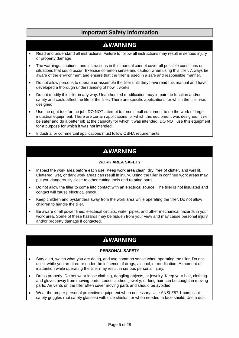
Important Safety Information
Read and understand all instructions. Failure to follow all instructions may result in serious injury
or property damage.
The warnings, cautions, and instructions in this manual cannot cover all possible conditions or
situations that could occur. Exercise common sense and caution when using this tiller. Always be
aware of the environment and ensure that the tiller is used in a safe and responsible manner.
Do not allow persons to operate or assemble the tiller until they have read this manual and have
developed a thorough understanding of how it works.
Do not modify this tiller in any way. Unauthorized modification may impair the function and/or
safety and could affect the life of the tiller. There are specific applications for which the tiller was
designed.
Use the right tool for the job. DO NOT attempt to force small equipment to do the work of larger
industrial equipment. There are certain applications for which this equipment was designed. It will
be safer and do a better job at the capacity for which it was intended. DO NOT use this equipment
for a purpose for which it was not intended.
Industrial or commercial applications must follow OSHA requirements.
WORK AREA SAFETY
Inspect the work area before each use. Keep work area clean, dry, free of clutter, and well lit.
Cluttered, wet, or dark work areas can result in injury. Using the tiller in confined work areas may
put you dangerously close to other cutting tools and rotating parts.
Do not allow the tiller to come into contact with an electrical source. The tiller is not insulated and
contact will cause electrical shock.
Keep children and bystanders away from the work area while operating the tiller. Do not allow
children to handle the tiller.
Be aware of all power lines, electrical circuits, water pipes, and other mechanical hazards in your
work area. Some of these hazards may be hidden from your view and may cause personal injury
and/or property damage if contacted.
PERSONAL SAFETY
Stay alert, watch what you are doing, and use common sense when operating the tiller. Do not
use it while you are tired or under the influence of drugs, alcohol, or medication. A moment of
inattention while operating the tiller may result in serious personal injury.
Dress properly. Do not wear loose clothing, dangling objects, or jewelry. Keep your hair, clothing
and gloves away from moving parts. Loose clothes, jewelry, or long hair can be caught in moving
parts. Air vents on the tiller often cover moving parts and should be avoided.
Wear the proper personal protective equipment when necessary. Use ANSI Z87.1 compliant
safety goggles (not safety glasses) with side shields, or when needed, a face shield. Use a dust
Page 6 of 28
mask in dusty work conditions. Also use non-skid safety shoes, hardhat, gloves, dust collection
systems, and hearing protection when appropriate. This applies to all persons in the work area.
Do not overreach. Keep proper footing and balance at all times.
Remove keys or wrenches before connecting the tiller to an air supply, power supply, or turning
on the tiller. A wrench or key that is left attached to a rotating part of the tiller may cause personal
injury.
Secure the work with clamps or a vise instead of your hand when practical. This safety precaution
allows for proper tool operation using both hands.
PRODUCT USE AND CARE
Do not force the tiller. Products are safer and do a better when used in the manner for which they
are designed. Plan your work, and use the correct product for the job.
Check for damaged parts before each use. Carefully check that the tiller will operate properly and
perform its intended function. Replace damaged or worn parts immediately. Never operate the
tiller with a damaged part.
Store the tiller when it is not in use. Store it in a dry, secure place out of the reach of children.
Inspect the tiller for good working condition prior to storage and before re-use.
Use only accessories that are recommended by the manufacturer for use with your tiller.
Accessories that may be suitable for one product may create a risk of injury when used with
another tool. Never use an accessory that has a lower operating speed or operating pressure
than the tool itself.
Keep guards in place and in working order. Never operate the tiller without the guards in place.
Specific Operation Warnings
⚠WARNING
ENTANGLEMENT HAZARD
To prevent serious injury or death from rotating driveline:
DO NOT operate without guards in place.
DO NOT operate higher than 540 RPM.
Keep hands, feet, clothing, and hair away from moving parts.
DO NOT operate without driveline securely attached at both ends.
DO NOT operate without driveline shields that turn freely on driveline.
CRUSHING AND PINCHING HAZARD
This implement is heavy. Use extreme caution when handling various parts of the machine.
Hands, fingers, and other body parts could be crushed or pinched between the tractor and the
implement.
DO NOT stand between the tractor and the implement when the tractor is in gear.
Make sure the parking brake is engaged before getting between the tractor and the implement.
DO NOT service the equipment while it is attached to the tractor.
Page 7 of 28
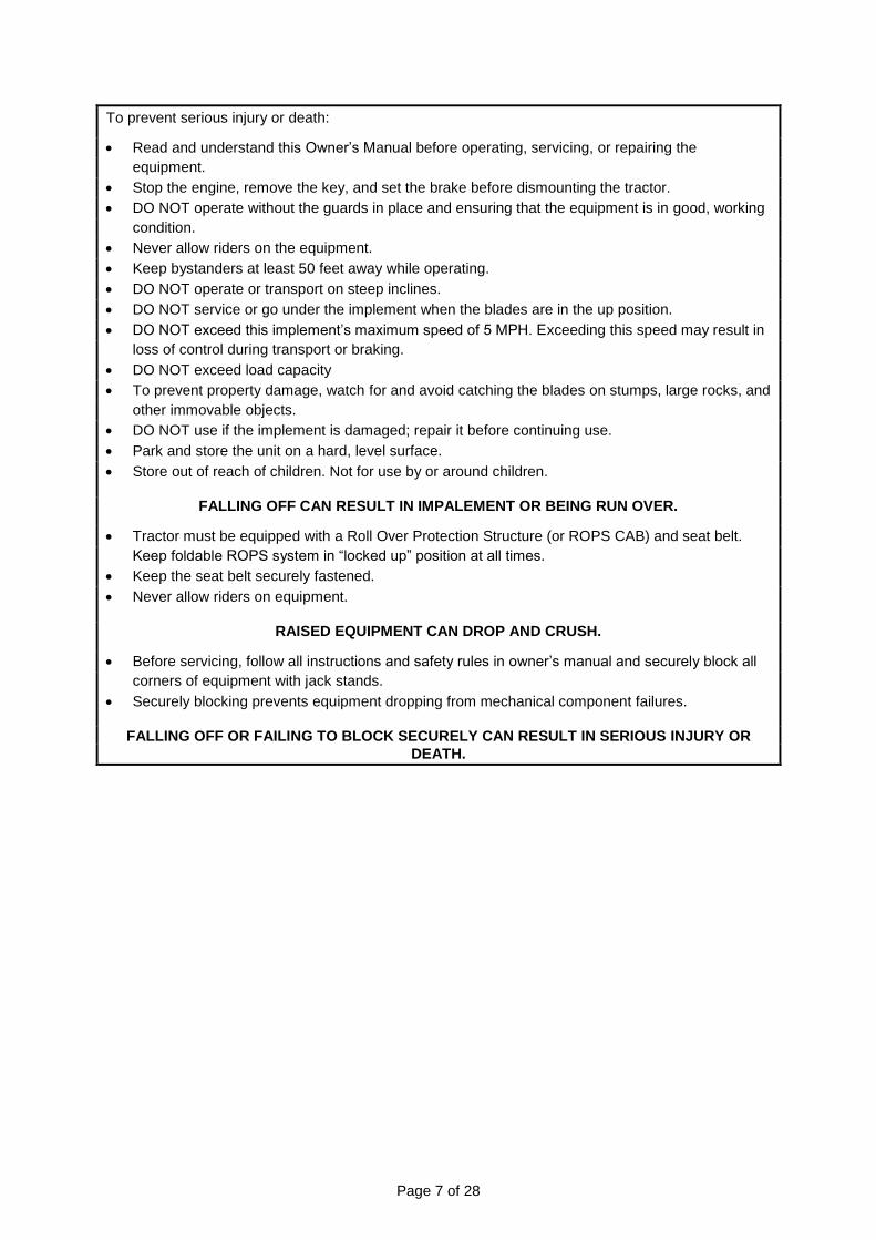
To prevent serious injury or death:
Read and understand this Owner’s Manual before operating, servicing, or repairing the
equipment.
Stop the engine, remove the key, and set the brake before dismounting the tractor.
DO NOT operate without the guards in place and ensuring that the equipment is in good, working
condition.
Never allow riders on the equipment.
Keep bystanders at least 50 feet away while operating.
DO NOT operate or transport on steep inclines.
DO NOT service or go under the implement when the blades are in the up position.
DO NOT exceed this implement’s maximum speed of 5 MPH. Exceeding this speed may result in
loss of control during transport or braking.
DO NOT exceed load capacity
To prevent property damage, watch for and avoid catching the blades on stumps, large rocks, and
other immovable objects.
DO NOT use if the implement is damaged; repair it before continuing use.
Park and store the unit on a hard, level surface.
Store out of reach of children. Not for use by or around children.
FALLING OFF CAN RESULT IN IMPALEMENT OR BEING RUN OVER.
Tractor must be equipped with a Roll Over Protection Structure (or ROPS CAB) and seat belt.
Keep foldable ROPS system in “locked up” position at all times.
Keep the seat belt securely fastened.
Never allow riders on equipment.
RAISED EQUIPMENT CAN DROP AND CRUSH.
Before servicing, follow all instructions and safety rules in owner’s manual and securely block all
corners of equipment with jack stands.
Securely blocking prevents equipment dropping from mechanical component failures.
FALLING OFF OR FAILING TO BLOCK SECURELY CAN RESULT IN SERIOUS INJURY OR
DEATH.

Page 8 of 28
Assembly Instructions
Tractor Requirements
The tractor horsepower and the hitch category should be within the range noted below. Tractors
outside the horsepower range must not be used.
Tractor Horsepower Rating . . . . . . . . . . . Up to 40-55 HP
3-Point Hitch Category . . . . . . . . . . . . . . . . . . Category 2
Structure of Tiller and Adjustment
The tiller is a farming implement driven by the tractor’s PTO shaft. The power of the tractor passes
through the PTO shaft and the gimbals’ assembly to the first axis of the middle gear case of the tiller.
It is decelerated and veered by a pair of bevel gears. It then is decelerated again by passing through a
pair of cylindrical gears (with two idle gears inside). After that, the power is transmitted to the blade
arbor through a coupling to the blade arbor spline shaft to drive the blades. Mid-way power
transmission is indicated in Figure 1.
Figure 1 – Structure of the Tiller

Page 9 of 28
Table 1 – Tiller Parts List
1 Gimbals Z1 bevel
2 First shaft Z2 gear
3 Second shaft Z3 cylindrical
4 Third shaft Z4
5 Fourth shaft Z5 gear
6 Blade arbor spline shaft
Z6 7 Left blade arbor
8 Right blade arbor
The tiller has a completely metal structure consisting of three parts: the transmission mechanism, the
working mechanism, and the auxiliary mechanism. The transmission mount mainly consists of the
gimbals, the assembly, and a gear box. The working unit consists of the blade arbor assembly and the
middle plough body unit. The auxiliary demount consists of the machine cover, the drag tiller, and the
frame suspending mount.
The gimbals assembly (see Figure 2 and Table 2) and grease nipple are installed on the cross shaft in
order to fill grease for lubrication of the needle bearings inside the cross shaft.
Figure 2 - Gimbals Assembly
Table 2 - Gimbals Assembly Parts List
Ref Name Part Number Quantity
1 hinged bolt ZT-02 4
2 split pin 3 ×25 GB/T91-2000 5
3 washer 14 GB/95-2002 4
4 hinged clamp ZT-01 2
Page 10 of 28
Ref Name Part Number Quantity
5 elastic collar for holes 40 GB/T893-1986 8
6 square shaft clamp ZT-03 1
7 washer 10 GB/T95-2002 1
8 square shaft bolt ZT-04 1
9 square shaft ZT-05 1
10 square axial sleeve clamp ZT-06.00 1
11 crossed shaft CA-10 JB/T524-1986 2
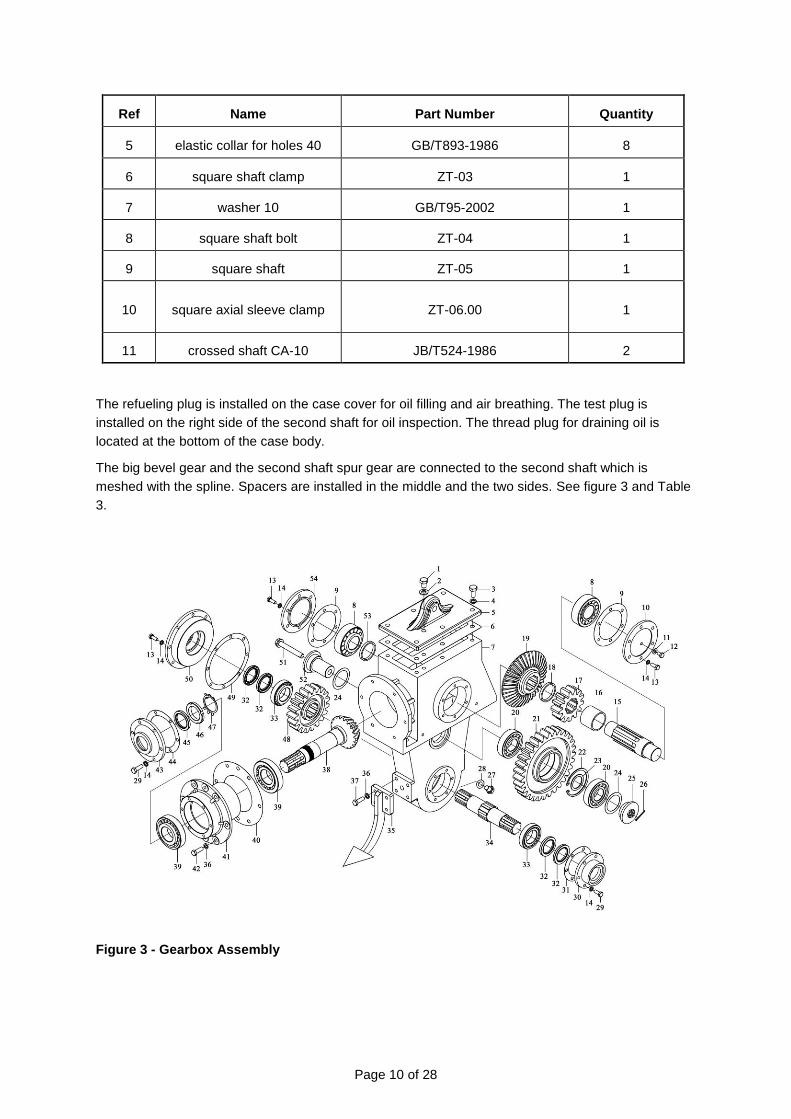
The refueling plug is installed on the case cover for oil filling and air breathing. The test plug is
installed on the right side of the second shaft for oil inspection. The thread plug for draining oil is
located at the bottom of the case body.
The big bevel gear and the second shaft spur gear are connected to the second shaft which is
meshed with the spline. Spacers are installed in the middle and the two sides. See figure 3 and Table
3.
Figure 3 - Gearbox Assembly

Page 11 of 28
Table 3 - Gearbox Assembly Parts List
Ref. Part No. Name Qty.
1 1GQN-180.105 Bolt 1
2 1GQN-180.106 Washer 1
3 GB/T5783 Bolt M14×30 6
4 GB/T93 Spring washer 14 6
5 1GQN-180.103 Upper cover 1
6 1GQN-180.104 Gasket 1
7 1GQN-180.102 Gearbox 1
8 GB/T297-1994 Bearing 32310 2
9 1GQN-180.135 Gasket 2
10 1GQN-180.125 Right bearing cover for 2nd shaft 1
11 Combine washer 12 1
12 1GQN-180.134 Oil check plug 1
13 GB/T93 Spring washer 10 32
14 GB/T5783 Bolt M10×30 20
15 1GQN-180.123 2nd shaft 1
16 1GQN-180.132 2nd shaft spacer bush 1
17 1GQN-180.120 Gear 1
18 1GQN-180.136 Small spacer bush 1
19 1GQN-180.126 Bevel gear 1
20 GB/T283-1994 Bearing NJ309 4
21 1GQN-180.115 Middle gear 2
22 GB/T893.1 Circlip 100 2
23 1GQN-180.137 Short spacer bush 2
24 1GQN-180.116 Gasket 4
25 1GQN-180.118 Cover 2
26 GB/T91 Pin 4×30 2
27 1GQN-180.101 Drain plug 1
28 Combine washer 20 1
29 GB/T5783 Bolt M10×25 12
30 1GQN-180.111 Right cover 1
31 1GQN-180.112 Gasket 1

Page 12 of 28
Ref. Part No. Name Qty.
32 GB/T9877.1 Oil seal 50×72×12 4
33 GB/T297-1994 Bearing 32210 2
34 1GQN-180.109 Spline shaft 1
35 1GQN-180.060 Small plough assy 1
36 GB/T93 Spring washer 12 10
37 GB/T5783 Bolt M12×30 4
38 1GQN-180.129 Bevel gear shaft 1
39 GB/T297-1994 Bearing 330311 2
40 1GQN-180.128 Gasket 1
41 1GQN-180.127 Sleeve ring 1
42 GB/T5783 Bolt M12×35 6
43 1GQN-180.130 Cover for 1st shaft 1
44 1GQN-180.131 Gasket 1
45 GB/T9877.1 Oil seal 40×65×12 1
46 GB/T812 Round nut M45×1.5 1
47 GB/T858 Stop washer 45 1
48 1GQN-180.108 Blade shaft gear 1
49 1GQN-180.114 Gasket 1
50 1GQN-180.113 Cover for left blade shaft 1
51 1GQN-180.119 Bolt 2
52 1GQN-180.117 Idle shaft 2
53 1GQN-180.107 Short spacer bush 1
54 1GQN-180.124 Left bearing cover 1
Refilling Oil
Before operating, always check the oil in the gearbox with the unit on level ground. If the unit has
more than one gearbox, make sure both are halfway full using GL5-85W 140 oil. DO NOT OVERFILL
OR DAMAGE WILL OCCUR TO THE GEARBOX.
1. Remove the top plug and the overflow plug from the side gearbox. Fill the side gearbox (using
the recommended gear oil) until the oil begins to flow out from the overflow plug hole.
2. Replace the top plug and the overflow plug and wipe away any excess oil.
3. Grease all zerks.
4. With the tiller positioned on level ground, adjust the tractor lift arms so that when they are lifted,
the rotor bar remains parallel to the ground.
5. With the tiller attached to the tractor, raise and support the tiller with secure blocking. Adjust the
Page 13 of 28
skids located on the sides of the tiller. The adjustment bolts for both the right and left sides
should be positioned in the same adjustment hole. This allows the tiller to till the same depth on
each side.
6. Raise the tiller and remove the blocking.
Slip Clutch Adjustment (when supplied)
The Slip Clutch is designed to slip so that the gearbox and driveline are protected if the implement
strikes an obstruction.
A new slip clutch or one that has been in storage over the winter may seize. Before operating the
implement, make sure it will slip by performing the following:
1. Turn off tractor engine and remove key.
2. Remove driveline from tractor PTO.
3. Loosen the cap screws to remove all tension from the spring plate.
4. Hold clutch hub solid and turn shaft to make sure clutch slips.
5. If clutch does not slip freely, dissemble and clean the thrust plate faces, flange yoke, and clutch
hub.
6. Reassemble clutch.
7. Finger tighten spring until it is against the thrust plate of the clutch and then tighten each of the
nuts by 1½ - 2 full rotations. Try the implement and watch for clutch to slip. Adjust nuts another
½ turn as needed until clutch stops slipping.
8. If clutch continues to slip when the spring is compressed, check friction disc for excessive wear.
Discs are 1/8” thick when new. Replace discs after 1/16” wear. Minimum disc thickness is 1/16”.
During Adjustment
During the adjustment, in case the gear side clearance conflicts with the meshing imprint (meshing
imprint is suitable while gear side clearance is not suitable), the meshing imprint should be followed
without guaranteeing the gear side clearance (gear side clearance should not be less than 0.2mm).
When disassembling and maintaining the unit, the quantity of shims should not be increased or
decreased and its thickness should not be changed.
Bearing Clearance: Adjusting the Blade Arbor Spline Shaft
If the symmetry plane of the blade arbor gear is overlapped with the symmetry plane of the gear box
body after the bearing clearance has been adjusted, it will still need to be adjusted. This can be done
by adding or removing the shims between the right or left bearing cover and box body. To prevent the
adjusted bearing clearance from being destroyed, the total quantity of shims should not be changed.
The number of shims being increased on the left side should be decreased on the right side, and vice
versa.
Page 14 of 28
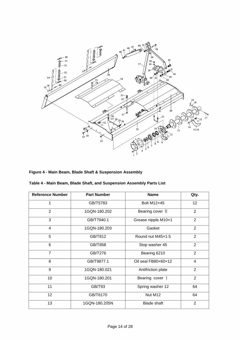
Figure 4 - Main Beam, Blade Shaft & Suspension Assembly
Table 4 - Main Beam, Blade Shaft, and Suspension Assembly Parts List
Reference Number Part Number Name Qty.
1 GB/T5783 Bolt M12×45 12
2 1GQN-180.202 Bearing cover Ⅱ 2
3 GB/T7940.1 Grease nipple M10×1 2
4 1GQN-180.203 Gasket 2
5 GB/T812 Round nut M45×1.5 2
6 GB/T858 Stop washer 45 2
7 GB/T276 Bearing 6210 2
8 GB/T9877.1 Oil seal FB80×60×12 4
9 1GQN-180.021 Antifriction plate 2
10 1GQN-180.201 Bearing cover Ⅰ 2
11 GB/T93 Spring washer 12 64
12 GB/T6170 Nut M12 64
13 1GQN-180.205N Blade shaft 2

Page 15 of 28
Reference Number Part Number Name Qty.
14 GB/T5783 Bolt M12×30 40
15 GB/T5669-1995 Left JF1801 Tilling Blade 20
16 GB/T5669-1995 Right JF1801 tiller blade 20
17 1GQN-180.314 Cotter pin 2
18 GB/T97.1 Washer 10 16
19 GB/T91 Pin 3×30 4
20 1GQN-180.315B Hood(right) 1
21 1GQN-180.408 U type bolt 4
22 1GQN-180.032 Main beam 1
23 GB/T5783 Bolt M14×35 6
24 1GQN-180.031 Tail connecting plate 2
25 GB/T5783 Bolt M12×40 2
26 GB/T93 Spring washer 10 12
27 GB/T6170 Nut M10 12
28 1GQN-180.313 Side cover 2
29 GB/T93 Spring washer 14 6
30 GB/T6170 Nut M14 6
31 GB/T5782 Bolt M18×65 4
32 GB/T93 Spring washer 18 4
33 GB/T6170 Nut M18 4
34 1GQN-180.315A Cover (left) 1
35 GB/T5783 Bolt M10×20 12
36 1GQN-180.030 Tail plate 1
37 1GQN-180.401 Support plate 2
38 1GQN-180.409 Spacer bush 1
39 1GQN-180.041 Suspension plate 2
40 GB/T6170 Nut M20 4
41 GB/T93 Spring washer 20 4
42 GB/T6170 Nut M24 2
43 GB/T93 Spring washer 24 2
44 1GQN-180.403 Lower suspension pin 2
45 GB/T5783 Bolt M20×60 2
46 GB/T5782 Bolt M20×120 1
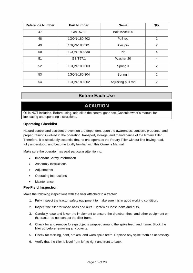
Page 16 of 28
Reference Number Part Number Name Qty.
47 GB/T5782 Bolt M20×100 1
48 1GQN-180.402 Pull rod 2
49 1GQN-180.301 Axis pin 2
50 1GQN-180.330 Pin 4
51 GB/T97.1 Washer 20 4
52 1GQN-180.303 Spring Ⅱ 2
53 1GQN-180.304 Spring Ⅰ 2
54 1GQN-180.302 Adjusting pull rod 2
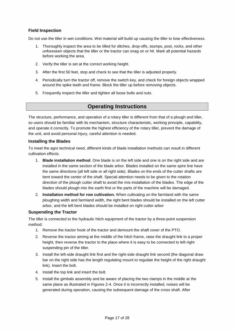
Before Each Use
Oil is NOT included. Before using, add oil to the central gear box. Consult owner’s manual for
lubricating and operating instructions.
Operating Checklist
Hazard control and accident prevention are dependent upon the awareness, concern, prudence, and
proper training involved in the operation, transport, storage, and maintenance of the Rotary Tiller.
Therefore, it is absolutely essential that no one operates the Rotary Tiller without first having read,
fully understood, and become totally familiar with this Owner’s Manual.
Make sure the operator has paid particular attention to:
Important Safety Information
Assembly Instructions
Adjustments
Operating Instructions
Maintenance
Pre-Field Inspection
Make the following inspections with the tiller attached to a tractor:
1. Fully inspect the tractor safety equipment to make sure it is in good working condition.
2. Inspect the tiller for loose bolts and nuts. Tighten all loose bolts and nuts.
3. Carefully raise and lower the implement to ensure the drawbar, tires, and other equipment on
the tractor do not contact the tiller frame.
4. Check for and remove foreign objects wrapped around the spike teeth and frame. Block the
tiller up before removing any objects.
5. Check for missing, bent, broken, and worn spike teeth. Replace any spike teeth as necessary.
6. Verify that the tiller is level from left to right and front to back.
Page 17 of 28
Field Inspection
Do not use the tiller in wet conditions. Wet material will build up causing the tiller to lose effectiveness.
1. Thoroughly inspect the area to be tilled for ditches, drop-offs, stumps, post, rocks, and other
unforeseen objects that the tiller or the tractor can snag on or hit. Mark all potential hazards
before working the area.
2. Verify the tiller is set at the correct working height.
3. After the first 50 feet, stop and check to see that the tiller is adjusted properly.
4. Periodically turn the tractor off, remove the switch key, and check for foreign objects wrapped
around the spike teeth and frame. Block the tiller up before removing objects.
5. Frequently inspect the tiller and tighten all loose bolts and nuts.
Operating Instructions
The structure, performance, and operation of a rotary tiller is different from that of a plough and tiller,
so users should be familiar with its mechanism, structure characteristic, working principle, capability,
and operate it correctly. To promote the highest efficiency of the rotary tiller, prevent the damage of
the unit, and avoid personal injury, careful attention is needed.
Installing the Blades
To meet the agro technical need, different kinds of blade installation methods can result in different
cultivation effects.
1. Blade installation method. One blade is on the left side and one is on the right side and are
installed in the same section of the blade arbor. Blades installed on the same spire line have
the same directions (all left side or all right side). Blades on the ends of the cutter shafts are
bent toward the center of the shaft. Special attention needs to be given to the rotation
direction of the plough cutter shaft to avoid the mis-installation of the blades. The edge of the
blades should plough into the earth first or the parts of the machine will be damaged.
2. Installation method for row cultivation. When cultivating on the farmland with the same
ploughing width and farmland width, the right bent blades should be installed on the left cutter
arbor, and the left bent blades should be installed on right cutter arbor
Suspending the Tractor
The tiller is connected to the hydraulic hitch equipment of the tractor by a three-point suspension
method:
1. Remove the tractor hook of the tractor and demount the shaft cover of the PTO.
2. Reverse the tractor aiming at the middle of the hitch frame, raise the draught link to a proper
height, then reverse the tractor to the place where it is easy to be connected to left-right
suspending pin of the tiller.
3. Install the left-side draught link first and the right-side draught link second (the diagonal draw
bar on the right side has the length regulating mount to regulate the height of the right draught
link). Insert the bolt.
4. Install the top link and insert the bolt.
5. Install the gimbals assembly and be aware of placing the two clamps in the middle at the
same plane as illustrated in Figures 2-4. Once it is incorrectly installed, noises will be
generated during operation, causing the subsequent damage of the cross shaft. After

Page 18 of 28
successful installation of the gimbals assembly, the bolt should be inserted and the splint pin
should be installed.
Starting the Tiller
1. Start the tractor and set at an idle RPM.
2. With the tiller lifted off the ground, engage the PTO, and slowly advance the throttle to 540
RPM. NOTE: The tiller is designed to run at 540 RPM ONLY.
3. Select a low gear on the tractor and begin to move forward. The tractor ground speed is to be
controlled by the gear selector ONLY and not the engine's speed. Travelling at a fast ground
speed while using the tiller could damage the unit. As the tractor moves forward, slowly lower
the tiller. Allow the tiller tines to gradually engage the ground.
4. The tiller is designed to be operated in a forward direction ONLY. Running in reverse could
damage it and the tractor, which will void the tiller's warranty. Adjust the back plate with the
regulating chain until the desired mulching effect is achieved. NOTE: NEVER ATTEMPT TO
ADJUST THE TILLER WHILE THE TRACTOR IS RUNNING.
5. Do NOT allow the tractor's engine or the tiller to bog down or stall. This causes undue wear
and tear on the tiller and the tractor. If this continues to happen, reduce the ground speed and
raise the tilling depth of the tiller. Never attempt to remove objects from the rotary bar until the
tractor has been shut down and the tiller tines have completely stopped.
Adjusting the Tiller Before Field Use
Several adjustments should be taken before the tiller is used in the field:
1. Left / right horizontal adjustment of the tiller. With the tractor parked on flat land, lower the tiller
until the blade edges are off the ground. Check that all the blades are the same distance off the
ground. If they are not, adjust the height using your tractor’s hitch draught link adjustment so the
left/right sides are the same distance from the ground.
2. Adjustment of gimbals assembly - front and back angle. Adjust the tiller to the required
ploughing depth, and check the gimbals to make sure the drive shaft angles (gimbals) in the
front and back are as straight as possible. Use the top link to adjust the angle of the drive shaft
(gimbal) to be as straight as possible. The length of the sheath for the square shaft should be
kept properly or it will damage the machine. Smaller angles are best. Adjust the tiller to the
required ploughing depth.
3. Make sure the drive shafts are equal for proper operation. Smaller angles are best.
4. Adjusting the ploughing depth. (Suspending to the Tractor section.)
5. Raising height adjustment of the tiller. The drive shaft/gimbals are not suitable for working under
large angles for extended periods of time. Make sure the drive shaft (gimbals) does not bind
with the tiller in the raised position. Normally, an 8-inch raised angle (from the blade edge to the
ground) is enough when turning the corner on a working field. Make sure it can turn the corner
with the PTO on. When passing through channels and ditches, or needing to rise to a higher
level on the road, turn the PTO off.
Using Advanced Speed
When using advanced speed, be sure to meet the needs of the broken soil and the flat, ditch bottom.
This will ensure a higher cultivation quality and it will also aid in high-efficiency, high-quality, and
lower-costs.
Under normal circumstances, the appropriate speed should be between 0.6-3 MPH. For compact or
hardened soil conditions, use 0.6-1.5 MPH. For loose soil conditions, higher speeds of 1.5 – 3 MPH
may be used.
Page 19 of 28
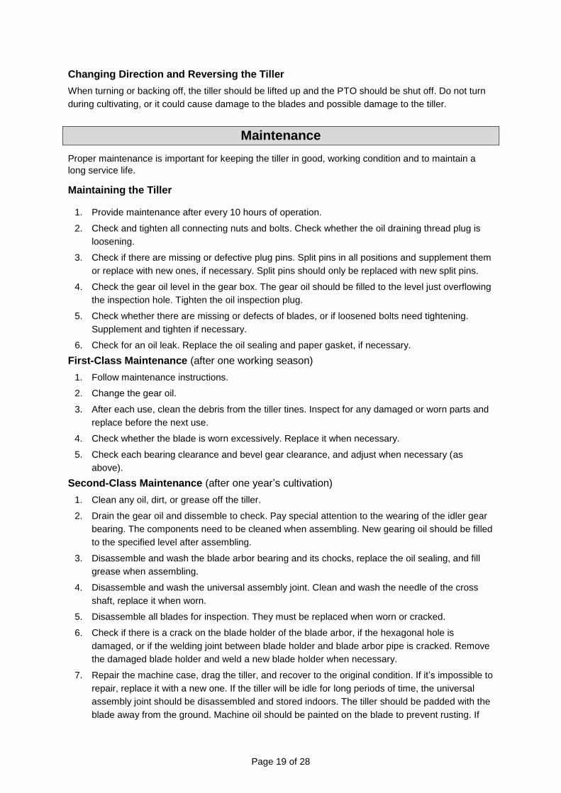
Changing Direction and Reversing the Tiller
When turning or backing off, the tiller should be lifted up and the PTO should be shut off. Do not turn
during cultivating, or it could cause damage to the blades and possible damage to the tiller.
Maintenance
Proper maintenance is important for keeping the tiller in good, working condition and to maintain a
long service life.
Maintaining the Tiller
1. Provide maintenance after every 10 hours of operation.
2. Check and tighten all connecting nuts and bolts. Check whether the oil draining thread plug is
loosening.
3. Check if there are missing or defective plug pins. Split pins in all positions and supplement them
or replace with new ones, if necessary. Split pins should only be replaced with new split pins.
4. Check the gear oil level in the gear box. The gear oil should be filled to the level just overflowing
the inspection hole. Tighten the oil inspection plug.
5. Check whether there are missing or defects of blades, or if loosened bolts need tightening.
Supplement and tighten if necessary.
6. Check for an oil leak. Replace the oil sealing and paper gasket, if necessary.
First-Class Maintenance (after one working season)
1. Follow maintenance instructions.
2. Change the gear oil.
3. After each use, clean the debris from the tiller tines. Inspect for any damaged or worn parts and
replace before the next use.
4. Check whether the blade is worn excessively. Replace it when necessary.
5. Check each bearing clearance and bevel gear clearance, and adjust when necessary (as
above).
Second-Class Maintenance (after one year’s cultivation)
1. Clean any oil, dirt, or grease off the tiller.
2. Drain the gear oil and dissemble to check. Pay special attention to the wearing of the idler gear
bearing. The components need to be cleaned when assembling. New gearing oil should be filled
to the specified level after assembling.
3. Disassemble and wash the blade arbor bearing and its chocks, replace the oil sealing, and fill
grease when assembling.
4. Disassemble and wash the universal assembly joint. Clean and wash the needle of the cross
shaft, replace it when worn.
5. Disassemble all blades for inspection. They must be replaced when worn or cracked.
6. Check if there is a crack on the blade holder of the blade arbor, if the hexagonal hole is
damaged, or if the welding joint between blade holder and blade arbor pipe is cracked. Remove
the damaged blade holder and weld a new blade holder when necessary.
7. Repair the machine case, drag the tiller, and recover to the original condition. If it’s impossible to
repair, replace it with a new one. If the tiller will be idle for long periods of time, the universal
assembly joint should be disassembled and stored indoors. The tiller should be padded with the
blade away from the ground. Machine oil should be painted on the blade to prevent rusting. If
Page 20 of 28
the splined shaft is stored in open air, it should be painted with grease in order to prevent any
rusting. Non-working surfaces with scratched paint should also be re-painted to prevent rust.
The tiller should be parked inside or covered outdoors.
Important: Be sure to check and tighten any loose bolts on the gear box before every use.
Troubleshooting
Problems Causes Solutions
Gimbals flying
off
1. Detachment of positioning pin. Install positioning pin.
2. Retaining ring flew out. Install check ring.
Driven output
shaft broken
1. Square shaft detached and clamping fork
continued running and broke.
Check the reason and change
new oil.
2. Gimbals stretch out and draw back;
blocked.
3. Excessive angle; cross shaft is broken.
4. Lowered to ground forcefully.
5. Overload due to bent blade touched with
big stone.
1. Right side and left side of the tiller is not in
the same level, and cultivating depth is
different.
Adjust the right side and left side
of tiller in the same level.
2. Right and left limit chain of the tractor is
not adjusted properly.
Adjust limit chain properly in order
to prevent tiller from swinging left
and right.
Cross shaft is
burned
1. Lack of oil in long term. Pay attention to maintenance.
2. Excessive angle; blocked. Pay attention to angles during
operation, make sure it’s not
blocked.
1. Foreign material fell inside during
assembly.
Take out foreign material.
2. Bevel gear meshed badly. Adjust according to specification.
3. Bearing damaged. Replace bearing.
4. Excessive wearing of gear. Replace or repair.
Blade shaft
cannot be
turned
1. Gear damaged and blocked. Replace gear.
2. Bearing damaged and blocked. Replace bearing.
3. Bevel gear has no side clearance. Adjust clearance.
4. Deformation of side plate. Fix or replace side plate.
5. Bending and deformation of blade shaft. Fix or replace blade shaft.
6. Grass and mud wrapped on blade shaft. Remove grass and mud.

Page 21 of 28
Problems Causes Solutions
Welding
detached of
blade holder
1. Poor welding quality. Re-weld.
2. Bent blade struck a rocky area. Tiller is not suitable for rocky and
rooted areas.
3. Bent blade is installed inversely, increasing its
resistance.
Install bend blade properly.
4. Tiller is dropped forcefully, bending blade received
excessive force.
Tiller should be lowered slowly
during operation.
Bent blade is
over bent or
broken
1. Hit rocks. Replace bent blade.
2. Still operating during turnaround. Should be lifted without operating
during turnaround.
3. Cracking occurred during heat treatment. Replace it.
4. Dropped to hard ground fiercely Drop slowly.
Welding
detached of
blade holder
1. Poor welding quality Re-weld.
2. Bent blade hit a rocky rooted area. Tiller is not suitable for rocky and
rooted land.
3. Bent blade is installed inversely, increasing its
resistance.
Install bent blade properly.
4. Tiller was dropped forcefully, bending blade received
excessive force.
Tiller should be lowered slowly
during operation.
Bent blade is
over bent or
broken
1. Hit rocks. Replace bent blade.
2. Still operating during turnaround. Should be lifted without operation
during turnaround.
3. Crack occurred during heat treatment. Replace it.
4. Dropped to the ground forcefully. Drop slowly.
Page 22 of 28
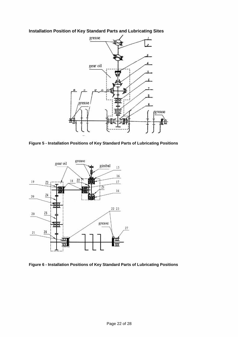
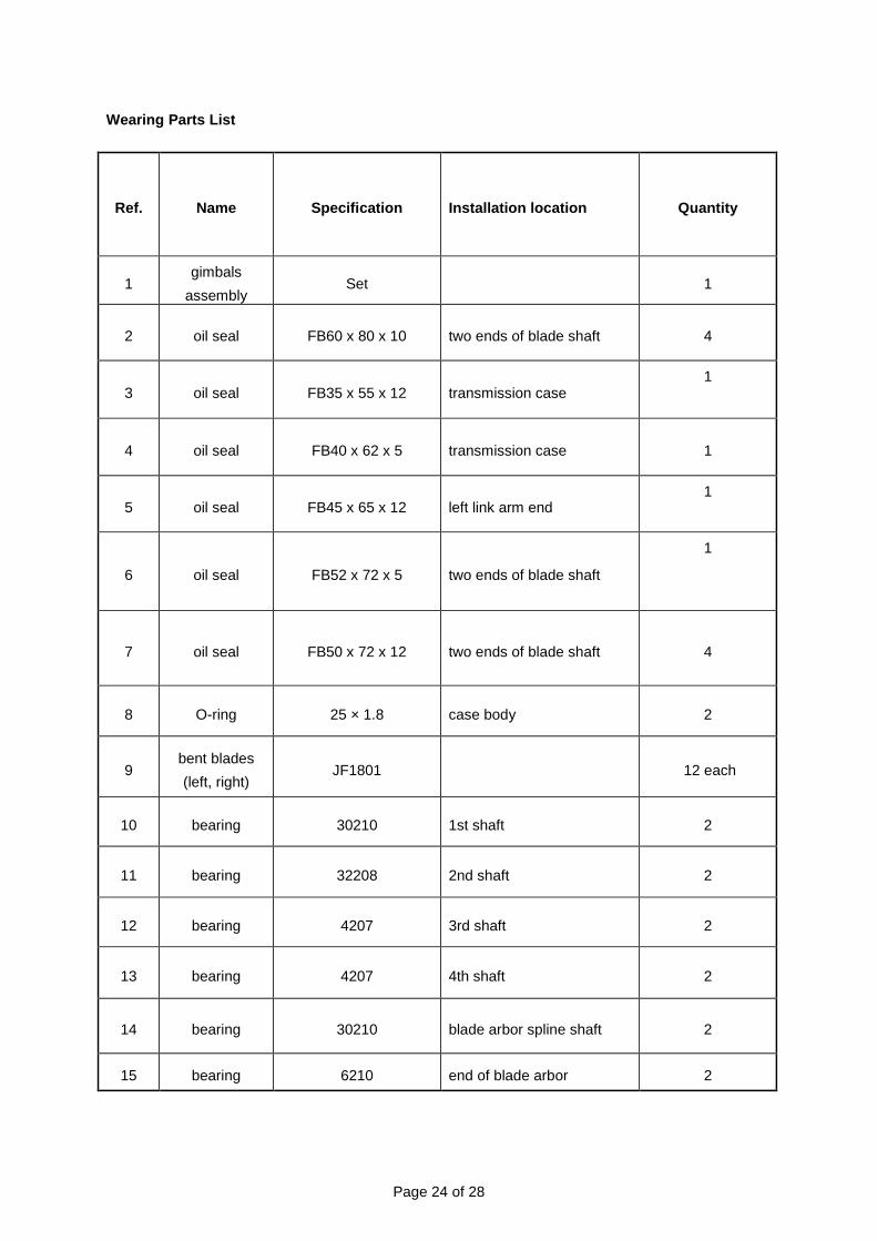
Installation Position of Key Standard Parts and Lubricating Sites
Figure 5 - Installation Positions of Key Standard Parts of Lubricating Positions
Figure 6 - Installation Positions of Key Standard Parts of Lubricating Positions

Page 23 of 28
Installation Location of the Standard Parts
Ref. Name Specification Installation location Quantity
1 cross joint 131 gimbals assembly 2
2 check ring GB/T893.1-1986 gimbals assembly 8
3 oil seal FB62 x 40 x 12 the 1st shaft 1
4 bearing 30210 the 1st shaft 2
5 bearing 32208 the 2nd
shaft 2
6 bearing 4207 the 3rd shaft 2
7 bearing 4207 the 4th shaft 2
8 bearing 30210 cutter arbor spline shaft 2
9 oil seal FB72 x 50 x 12 cutter arbor spline shaft 4
10 bearing 6210 shaft end of cutter arbor 2
11 oil seal FB80 x 60 x 10 shaft end of cutter arbor 4
12 hexagonal bolt M12 ×30 tool post of cutter arbor 24
13 nut M12 tool post of cutter arbor 24
Page 24 of 28
Wearing Parts List
Ref. Name Specification Installation location Quantity
1 gimbals
assembly Set
1
2 oil seal FB60 x 80 x 10 two ends of blade shaft 4
3 oil seal FB35 x 55 x 12 transmission case 1
4 oil seal FB40 x 62 x 5 transmission case 1
5 oil seal FB45 x 65 x 12 left link arm end 1
6 oil seal FB52 x 72 x 5 two ends of blade shaft
1
7 oil seal FB50 x 72 x 12 two ends of blade shaft 4
8 O-ring 25 × 1.8 case body 2
9 bent blades
(left, right) JF1801
12 each
10 bearing 30210 1st shaft 2
11 bearing 32208 2nd shaft 2
12 bearing 4207 3rd shaft 2
13 bearing 4207 4th shaft 2
14 bearing 30210 blade arbor spline shaft 2
15 bearing 6210 end of blade arbor 2

Page 25 of 28
Parts Shipped with Machine
Ref. Name Specification Quantity
1 gimbals
assembly set 1
2 bolt M12×30 24
3 nut M12 24
4 plough body
assembly piece 1
5 left bent blade JF1801 12
6 right bent blade JF1801 12
7 manual
1
8 certificate of
approval
1

Page 26 of 28
Replacement Parts
For replacement parts and technical questions, please call Customer Service at 1-800-222-5381.
Not all product components are available for replacement. The illustrations provided are a
convenient reference to the location and position of parts in the assembly sequence.
When ordering parts, the following information will be required: item description, item model
number, item serial number/item lot date code, and the replacement part reference number.
The distributor reserves the rights to make design changes and or improvements to product lines
and manuals without notice.
Page 27 of 28
Limited Warranty
Northern Tool and Equipment Company, Inc. ("We'' or '"Us'') warrants to the original purchaser only
("You'' or “Your”) that the Nortrac product purchased will be free from material defects in both
materials and workmanship, normal wear and tear excepted, for a period of one year from date of
purchase. The foregoing warranty is valid only if the installation and use of the product is strictly in
accordance with product instructions. There are no other warranties, express or implied, including the
warranty of merchantability or fitness for a particular purpose. If the product does not comply with this
limited warranty, Your sole and exclusive remedy is that We will, at our sole option and within a
commercially reasonable time, either replace the product or product component without charge to You
or refund the purchase price (less shipping). This limited warranty is not transferable.
Limitations on the Warranty
This limited warranty does not cover: (a) normal wear and tear; (b) damage through abuse, neglect,
misuse, or as a result of any accident or in any other manner; (c) damage from misapplication,
overloading, or improper installation; (d) improper maintenance and repair; and (e) product alteration
in any manner by anyone other than Us, with the sole exception of alterations made pursuant to
product instructions and in a workmanlike manner.
Obligations of Purchaser
You must retain Your product purchase receipt to verify date of purchase and that You are the original
purchaser. To make a warranty claim, contact Us at 1-800-222-5381, identify the product by make
and model number, and follow the claim instructions that will be provided. The product and the
purchase receipt must be provided to Us in order to process Your warranty claim. Any returned
product that is replaced or refunded by Us becomes our property. You will be responsible for return
shipping costs or costs related to Your return visit to a retail store.
Remedy Limits
Product replacement or a refund of the purchase price is Your sole remedy under this limited warranty
or any other warranty related to the product. We shall not be liable for: service or labor charges or
damage to Your property incurred in removing or replacing the product; any damages, including,
without limitation, damages to tangible personal property or personal injury, related to Your improper
use, installation, or maintenance of the product or product component; or any indirect, incidental or
consequential damages of any kind for any reason.
Assumption of Risk
You acknowledge and agree that any use of the product for any purpose other than the specified
use(s) stated in the product instructions is at Your own risk.
Governing Law
This limited warranty gives You specific legal rights, and You also may have other rights which vary
from state to state. Some states do not allow limitations or exclusions on implied warranties or
incidental or consequential damages, so the above limitations may not apply to You. This limited
warranty is governed by the laws of the State of Minnesota, without regard to rules pertaining to
conflicts of law. The state courts located in Dakota County, Minnesota shall have exclusive jurisdiction
for any disputes relating to this warranty.

Page 28 of 28
Distributed by:
Northern Tool & Equipment Company, Inc.
Burnsville, Minnesota 55306
www.northerntool.com
Made in China


![Operator’s Manual Front Tine Rotary Tiller - Powermate · Operator’s Manual Front Tine Rotary Tiller KEEP THIS MANUAL FOR FUTURE REFERENCE MODEL No. P-FTT-160MD-[E] P-FTT-160MD](https://img.pdfslide.us/doc/110x75/5b87befe7f8b9aaf728c0b5b/operators-manual-front-tine-rotary-tiller-operators-manual-front-tine.jpg)