Embed Size (px)
DESCRIPTION
ATS panel handbook
Citation preview
CONTENTS PAGE 1.0 Safety 1 2.0 Installation 1 2.1 Electrical installation 1 3.0 ATS Panel Equipment 1 3.1 ATS control – ENKO ATS 1.1 1 3.2 Monitoring and Indicators 1-2 3.3 Modes of operation 2 3.4 ATS 1.1 Programming 2-3 3.5 ATS 1.1 Parameters 3 3.6 Battery charger on/off switch & lamp 4 3.7 Change over contactors 4 3.8 Control fuses 4 3.9 AC Ammeter 4 3.10 Emergency stop 4 4.0 Check list for automatic operation 4 5.0 System test 4 6.0 Warranty 4 3 Phase Auto Transfer Switch wiring diagram 5 ATS Generator Mains Interconnection Wiring 6
AUTOMATIC TRANSFER SWITCH PANEL (ATS)
3 Phase 400v
OPERATION AND MAINTENANCE
Stephill Generators Ltd Wallis close
Park Farm South Wellingborough Northants NN8 6AG
Tel : +44 (0)1933 677911 Fax: +44 (0)1933 677916
E-mail : [email protected]
Web : www.stephill-generators.co.uk

1
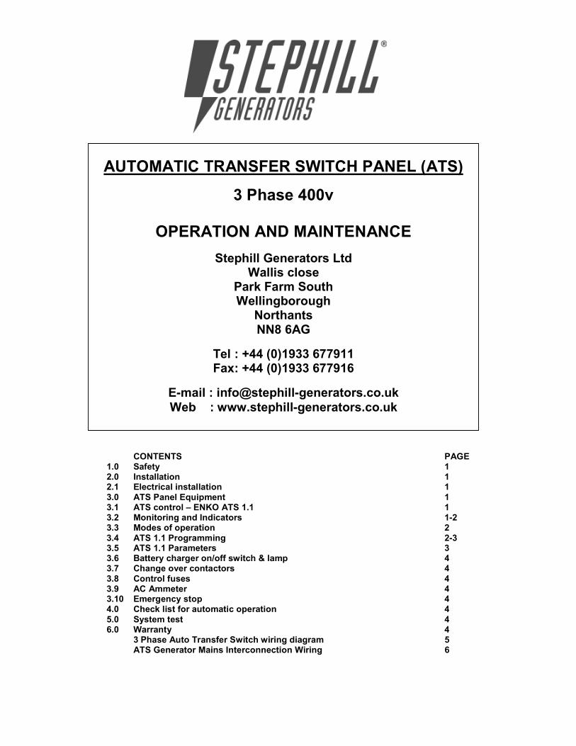
1 Safety Warning ATS Panel should only be installed, maintained or serviced by a qualified electrician. The generator set may start without warning whilst in AUTO mode. Before undertaking any service or maintenance work, ensure the mains and generator supply are isolated and generator is switched to off. The generator is supplied with the battery disconnected/isolated for safety reasons and should not be re-connected until all connections have been made. Because of the nature of the equipment and the permanent mains connection, the terminals within the generator may be LIVE even if the generator itself is not running. 2 Installation Make sure that the Generator is at least one metre away from any building during operation. Operate in a well ventilated unconfined area, so that fumes can be properly dispersed. Silencer outlet should be facing an open area to prevent fumes being recirculated. Consideration will also need to be made for refuelling and maintenance. If installing in a confined area please consult manufacturer. 2.1 Electrical installation AC Wiring Please ensure the correct cross sectional area of cable between the Alternator/Panel and Distribution board used is adequate to carry the full rated continuous output of the generator, allowing for derating in high ambient temperatures. Please consult IEE regulations as per the correct sizing of cable and other issues regarding wiring. Flexible cable is recommended for alternator connections allowing for a generous loop before the cable enters the alternator terminal box because of the vibration caused by the set starting. If this is not possible a terminal box can be fitted nearby and flex fitted between this and the generator terminal box. These precautions will not be needed when fixing to a control box which is not attached to the Alternator. Please refer to Wiring diagram. DC Wiring For the DC wiring we recommend 1.5mm if the generator is more than 10Meters away please consult manufacturer for cable sizing. Please refer to Wiring diagram. 3 ATS Panel Equipment 3.1 ATS control – ENKO ATS 1.1 ATS1.1 automatic transfer unit is a microprocessor based digital unit monitoring the 3 phases of the mains and controls the changeover of mains and generator contactors if a mains failure on any phase is detected. The module is able to display all the parameters which are essential for the basic gen-set transfer control.The module has 3 operation modes.Test on load, test off load and Auto operation modes can be chosen via the push-buttons mounted on the front panel. 3.2 Monitoring and Indicators:
« = MENU By pressing the menu button the voltage and frequency measurements can be displayed on the unit. • L1-N Mains Voltage • L2-N Mains Voltage • L3-N Mains Voltage

2
• Mains Frequency • L13 Mains Voltage R-T • L23 Mains Voltage S-T • L12 Mains Voltage R-S • L1-N Generator Voltage • Generator Frequency Display Leds: • G: Indicates the displayed value is a generator voltage or frequency • M: Indicates the displayed value is a mains voltage or frequency 3.3 Modes of operation OFF Mode: The module is placed into OFF mode by pressing MENU & TEST OFF LOAD buttons together. OFF mode is used for stopping the engine. If OFF button (MENU & TEST OFF LOAD) is pressed while the module is in AUTO , TEST ON or TEST OFF modes, the module will de-energise the generator contactor output relay if they are energised, and if the engine is running on load the module will allow the alternator to run off load to cool it adequately. When the cooling time is expired, the module will de-energise the start output and the engine is brought to rest. AUTO Mode: The module is placed into auto mode by pressing auto button. If a mains failure on any phase is detected after the mains failure delay timer expires, the load is switched off from the mains and the ATS unit will automatically issue a start command to the genset controller by using the parameters settings. When the generator operates within the limits the load is transferred to the generator by the ATS module .When the mains supply has been restored after the mains transition delay timer expires, the ATS module will transfer the load back from the generator to the mains supply and remove the start command from the genset controller after the cooling time. In case of a failure while operating, the unit will stop the generator automatically. A clear mimic diagram and LEDs provide information about the load status and voltages. TEST ON LOAD : This is used to manually start the engine on load even when the mains voltage is within the limits. TEST OFF LOAD : This is used to manually start the engine off load even when the mains voltage is within the limits. The load is supplied by the mains but if the mains supply fails, then the load is transferred to the generator automatically. 3.4 ATS 1.1 Programming Press “MENU & TEST OFF LOAD” buttons simultaneously (display = - - -) Press “MENU” (display = 000) Press “TEST OFF LOAD” until number 001 appears. Press “MENU” (display = P00) Press “TEST OFF LOAD” to change program number. Press “A” to change program number digit. After selecting the program number pressing menu button again will place the unit into the parameter mode. The parameter can then be adjusted. Press “TEST OFF LOAD” to increase number. Press “TEST ON LOAD” to decrease number. Press “A” to change program number digit. Press “MENU” to confirm new value.

3
The configured value is written to the memory with display flashing 3 times. If the adjusted password is faulty, faulty message (Err) is displayed. If the adjusted parameter is out of limits, faulty message (Err) is displayed for 3 seconds and the parameter will have to be adjusted again. To leave from the programming menu, off button (“MENU & TEST OFF LOAD” button) has to be pressed. Press “A” to place unit back into auto. 3.5 ATS 1.1 Parameters
Parameter Configurable parameter: Setting P0 Customer Code:
P1 Generator voltage lower limit: 207
P2 Generator voltage upper limit: 253
P3 Generator frequency lower limit: 45
P4 Generator frequency upper limit: 55
P5 Mains voltage lower limit: 207
P6 Mains voltage upper limit: 260
P7 Mains frequency lower limit: 45
P8 Mains frequency upper limit: 55
P9 Voltage Hysterisis: 10
P10 Remote Start output delay: 3
P11 Generator fault control delay: 5
P12 Mains transition delay: 30
P13 Mains fault control delay: 3
P14 Mains contactor delay: 1
P15 Generator contactor delay: 5
P16 Engine cooling duration: 180
P17 Mains Frequency Enable: 1
P18 Generator Frequency Enable: 1
P19 Remote Start Output Selection: 0
P20 Aux Input 1: 10
P21 Input Configuration: 0
P22 Aux Input 2: 0
P23 Input Configuration:
P24 Aux Input 3: 0
P25 Input Configuration:
P26 Aux Output 1: 0
P27 Output Configuration:
P28 Aux Output 2: 0
P29 Output Configuration:
P30 Fault control delay: 4
P31 Default parameters: 0
P32 Password: 1
P33 Power On Operating Mode: 1
P34 Mains control in off mode: 1
P35 Calibrations L1 145
P36 Calibrations L2 145
P37 Calibrations L3 145
P38 Calibrations GEN 145

4
3.6 Battery charger On/Off switch & lamp To isolate the mains operated battery charger which maintains the engine starter battery to a healthy condition. Under normal circumstances this is left in the on position, with lamp illuminated. 3.7 Change over contactors Pair of suitably rated contactors, one for each supply, electrically and mechanically interlocked to avoid paralleling of supplies. 3.8 Control fuses Refer to circuit diagram for fuse ratings. 3.9 AC Ammeter Monitors AC Current on Load. 3.10 Emergency stop
When the Emergency stop is activated, the module will de-energise generator contactor output relay. The module will issue a stop command to stop the generator at the same time. 4 Check list for automatic operation 1. Auto mode selected on ATS 1.1 unit. 2. Generator output MCB in on position. 3. Generator in auto mode. 3. Battery charger switched on. 5 System test It is recommended that the generator is tested every week and run on load for 30 minutes.
6 Warranty All equipment supplied by STEPHILL GENERATORS LTD carries a warranty of 12 months from date of despatch. During the warranty period, should the plant fail due to faulty design, materials or workmanship by STEPHILL or it’s sub-contractors, we undertake to rectify the fault by replacement or repair at our option. STEPHILL will accept no responsibility whatsoever for equipment that has failed due to; - Improper repair or use of parts not supplied by STEPHILL. - Lack of, or incorrect maintenance. - Fair wear and tear, misuse, negligence, accidental damage, improper storage, incorrect starting / warm-up / run-in or shutdown. No warranty claim will be considered by STEPHILL unless any defective parts are available for inspection by us, or our nominees, to determine the reason or cause of failure, and STEPHILL is given the option of repair or replacement. STEPHILL are not responsible for incidental or consequential damages, downtime, or other costs due to warrantable failure, and unauthorised alterations made to any product supplied by STEPHILL.


1
ATS1.1 AUTOMATIC TRANFER SWITCH KONTROL UNIT
OPERATORS MANUAL
INTRODUCTION
ATS 1.1 automatic transfer unit is a microprocessor based digital unit monitoring the 3 phases
of the mains and controls the changeover of mains and generator contactors if a mains failure
on any phase is detected. The module offers a very cost effective and space saving solutions
as it is able to display all the parameters which are essential for the basic genset transfer
control. The module has 3 operation modes. Test on load, test off load and Auto operation
modes can be chosen via the push-buttons mounted on the front panel. The 39 parameter
settings can also be adjusted from the front panel. So the module can be adapted to all
generators without the need of any other unit or module.
Features:
• Micro-processor based design
• Automatic engine starting and stopping commands
• Automatic load transfer
• Configurable via front panel
• Automatic shut down on fault condition
• Test on / off modes
• LED mimic indication
• Operate with cranking dropouts
• 2 configurable auxiliary outputs
• 3 configurable auxiliary inputs
2
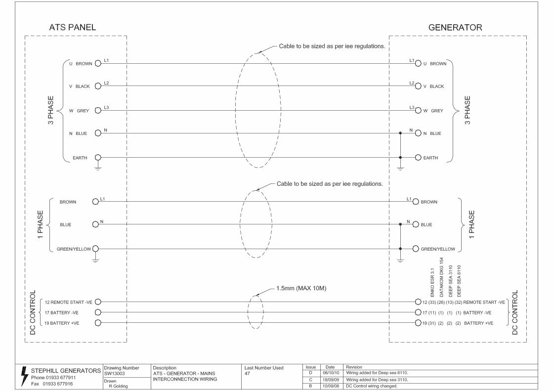
• 3 phase true RMS mains voltage measuring and monitoring
• Mains frequency measuring and monitoring
• Generator phase true RMS voltage measuring and monitoring
• Generator frequency measuring and monitoring
• Digitally adjustable low&high mains and generator voltage limits
• Digitally adjustable generator start command timings
• Digitally adjustable generator overspeed /underspeed limits
• Digitally adjustable mains voltage overspeed/underspeed limits
• Digitally adjustable auxiliary inputs specifications
• Digitally adjustable auxiliary outputs specifications
• Digitally adjustable load transfer timings
• Failure control
• Digitally adjustable warm up/cooling timings
• Digitally adjustable measurement calibrations
• Digital display
• Low cost,small dimensions
Inputs/Outputs:
• 3 phase mains voltage inputs
• Single phase generator voltage input
• 12 / 24 V battery voltage inputs
• Auxiliary1 input
• Auxiliary2 input
• Auxiliary3 input
• Auxiliary1 output
• Auxiliary2 output
• Start command output
• Generator contactor relay output
• Mains contactor relay output

3
Front View
Display: By pressing the menu button in auto ,test on ,test off mode, the voltage and
frequency measurements can be displayed on the unit.
• L1-N Mains Voltage
• L2-N Mains Voltage
• L3-N Mains Voltage
• Mains Frequency
• L13 Mains Voltage R-T
• L23 Mains Voltage S-T
• L12 Mains Voltage R-S
• L1-N Generator Voltage
• Generator Frequency
Display Leds:
• G: Indicates the displayed value is a generator voltage or frequency
• M: Indicates the displayed value is a mains voltage or frequency
Automatic Button: Auto button places the unit into automatic mode.
Test On Button:Test on button places the unit into test on mode.
Test Off Button:Test off button places the unit into test off mode.
Off Button(Test Off+Menu button): Off button places the unit into off mode.
Menu Button: By pressing the menu button in auto,test on or test off mode,the voltage and
frequency values can be displayed on the unit.If the unit is into off mode, pressing the menu
button will place the unit into the password mode.In password mode, the password which will

4
be adjusted can be choosen with test on(decrease),test off(increase) and auto(changing the
digit number) button.After accsessing the correct password, by pressing menu button again
will place the unit into the menu mode. In menu mode, the menu parameter which will be
adjusted can be choosen with the buttons .After selecting the menu parameter, by pressing
menu button again will place the unit into the parameter mode. The parameter can be adjusted
with the buttons and by pressing menu or off mode , the new parameter is written to the
memory .To cancel the menu operations, off button should be pressed.
Mains Contactor Led:Mains contactor LED is activated when the unit energise the mains
contactor .
Mains Voltage Led: Mains Voltage LED is activated when the unit detects main voltage in
limits.It blinks during the mains voltage safety time after the mains voltage returns.
Generator Contactor Led: Generator contactor LED is activated when the unit energise the
generator contactor .
Generator Voltage Led: Generator Voltage LED is activated when the unit detects
generator voltage in limits.
Rear View
INPUTS
OUTPUTS
G
OUTPUTS
NU
GEN
MA
INSNTSR
1 2 3 4 5 6 7 8
9 10 11 12 13 14 15 16 17 18 19
C F
AIL
STA
RT
ALA
RM
AU
X.
FU
EL
OV
ER
CU
R.
LO
P
HET
BA
TT(+
)
BA
TT(-)
AU
X.
TERMINAL CONNECTIONS
Terminal
No:
Description: Notes:
1 N Alternator Neutral sensing input
2 U Alternator R phase voltage sensing input
3 N Mains Neutral sensing input
4 T Mains T phase voltage sensing input
5 S Mains S phase voltage sensing input
6 R Mains R phase voltage sensing input
7 GEN CON. Outputs alternator R phase voltage to energise the
generator contactor.
8 MAINS CON. Outputs mains R phase voltage to energise the mains
contactor .
9 COM1 Common input for aux output relays

5
10 AUX.OUT1 Configurable output relay
11 AUX.OUT2 Configurable output relay
12 START Start command output relay
13 COM2 Common input for start output relay
14 AUX.IN1 Configurable input(negative closing switch input)
15 AUX.IN2 Configurable input(negative closing switch input)
16 AUX.IN3 Configurable input(negative closing switch input)
17 BAT(-) DC - supply input
18 BAT(+) DC + supply input
OPERATION MODES
OFF Mode:
The module is placed into off mode by pressing MENU + TEST OFF buttons together.Off
mode is used for stopping the engine.If off button(menu+test off buttons) is pressed while the
module is in auto , test on or test off modes, the module will de-energise generator contactor
output relay if they are energised and if the engine is running on load, the modul allow the
alternator to run off load to cool it adequately.When the cooling time is expired, the module
will de-energise the start output and the engine is brought to rest.
While the module is in off mode, by pressing the menu button, 39 parameters can be
adjusted.
AUTO Mode: The module is placed into auto mode by pressing auto button. If a mains failure on any phase
is detected after the mains failure delay timer expires, the load is switched off from the mains
and the ATS unit automatically will issue a start command to the genset controller by using
the parameters settings which are adjusted before. When the generator operates within the
limits adjusted before, the load is transferred to the generator by the ATS module .When the
mains supply has been restored after the mains transition delay timer expires, the ATS module
will transfer the load back from the generator to the mains supply and remove start command
from the genset controller after cooling time. In case of a failure while operating, the unit will
stop the generator automatically. A clear mimic diagram and LEDs provide information about
the load status and voltages.
TEST ON Mode :
This is used to manually start the engine on load even the mains voltage is within the limits.
TEST OFF Mode :
This is used to manually start the engine off load even the mains voltage is within the limits.
The load is supplied by the mains but if the mains supply fails, then the load is transferred to
the generator automatically.

6
INPUTS/OUTPUTS
DC Supply Input:Battery + DC supply is connected to BATT+ terminal.Battery – DC supply
is connected to BATT- terminal.The modul is protected to reverse connection.12/24V battery
can be connected by using the same terminals.
Alternator Input:Alternator single phase and neutral outputs are connected alternator inputs
of the modul.Alternator voltage and frequency are monitored from these inputs.
Mains Input:Mains 3 phase and neutral supply voltage is connected mains inputs of the
modul.Mains voltage and frequency are monitored from these inputs.If only one phase of the
mains voltage is required to be monitored, other mains voltage inputs of the modul have to be
short circuited with the connected phase voltage.
Auxiliary Input 1:Auxiliary input can be configured as Normally Open input and Normally
Close input by adjusting P21 number of the parameter.And the function can be configured as
unused,remote start on load, remote start off load, mains simulate ,mains disable, auto start
disable,mains contactor disable, generator contactor disable,C type failure input, D type
failure input, E type failure input , F type failure input by adjusting the P20 parameter
number.If this input will not be used, it has to be configured as NO(P21) and unused(P20)
and leaved empty.It is a negative closing switch.
Auxiliary Input 2:Auxiliary input can be configured as Normally Open input and Normally
Close input by adjusting P23 number of the parameter.And the function can be configured as
unused,remote start on load, remote start off load, mains simulate ,mains disable, auto start
disable,mains contactor disable, generator contactor disable,C type failure input, D type
failure input, E type failure input , F type failure input by adjusting the P22 parameter
number.If this input will not be used, it has to be configured as NO(P23) and unused(P22)
and leaved empty. It is a negative closing switch.
Auxiliary Input 3:Auxiliary input can be configured as Normally Open input and Normally
Close input by adjusting P25 number of the parameter.And the function can be configured as
unused,remote start on load, remote start off load, mains simulate ,mains disable, auto start
disable,mains contactor disable, generator contactor disable,C type failure input, D type
failure input, E type failure input , F type failure input by adjusting the P24 parameter
number.If this input will not be used, it has to be configured as NO(P25) and unused(P24)
and leaved empty. It is a negative closing switch.
Mains Contactor Relay Output(250VAC 10A):Mains contactor output is used for
energising the mains contactor to transfer load to the mains.It outputs R phase of the mains
from its normally close terminal.
Generator Contactor Relay Output(250VAC 10A): Generator contactor output is used for
energising the generator contactor to transfer load to the generator.It outputs R phase of the
generator from its normally open terminal.

7
Starter Command Relay Output(250VAC 6A): It outputs the signal connected to com2 .It
is activated when the modul issues a start command.
Auxiliary Relay Output 1(250VAC 6A): Auxiliary output can be configured as mains
failure output, generator failure output, engine running output,generator on load output, mains
on load output,auto mode ready output,module is available output, failure output by adjusting
the P26 parameter number.By adjusting the P27 parameter number, the auxiliary relay output
is configured as normally open output or normally close output. It outputs the signal
connected to com1.
Auxiliary Relay Output 2(250VAC 6A): Auxiliary output can be configured as mains
failure output, generator failure output, engine running output,generator on load output, mains
on load output,auto mode ready output,module is available output, failure output by adjusting
the P28 parameter number.By adjusting the P29 parameter number, the auxiliary relay output
is configured as normally open output or normally close output. It outputs the signal
connected to com1.
FAILURES
Auxiliary inputs can be configured as C type failure input, D type failure input, E type failure
input , F type failure input.Failures are self-acknowledge.When the failure conditions are
restored and the failure input is de-activated, failures are reset.If the auxiliary failure is
adjusted as one of D,E,F type failures, this input has to be de-activated before the ATS modul
issues a start command.
C type failure:When the aux failure input is activated, the modul will de-energise generator
contactor output relay.But the engine goes on running.When the failure input is de-activated,
the modul will energise the generator contactor again.
D type failure:When the aux failure input is activated, the modul will de-energise generator
contactor output relay.But the engine goes on running off load until the cooling time
expires.When the cooling time expires, the modul will issue stop command to stop the
generator.
E type failure:When the aux failure input is activated, the modul will de-energise generator
contactor output relay.The modul will issue stop command to stop the generator at the same
time.
F type failure:When the aux failure input is activated, the modul will de-energise generator
contactor and mains contactor output relays.The modul will issue stop command to stop the
generator at the same time.

8
PROGRAMING PARAMETERS
Moduls are easily programmed and the parameters are displayed and configured by using
push-buttons on the front panel.If the unit is off mode, pressing the menu button will place
the unit into the password mode.In password mode, the password which will be adjusted can
be choosen with test on(decrease),test off(increase) and auto(changing the digit number)
button.After accsessing the correct password, by pressing menu button again will place the
unit into the menu mode. In menu mode, the menu parameter which will be adjusted can be
choosen with the buttons .After selecting the menu parameter, by pressing menu button again
will place the unit into the parameter mode. The parameter can be adjusted with the buttons
and by pressing menu button, the configured value is written to the memory with display
flashing 3 times .With the pressing off button, off mode is returned.To cancel the parameter
configuration,off button has to be pressed.
If the adjusted password is faulty, faulty message(Err)is displayed.And one of the buttons
have to be pressed to place into a operating modes.
If the adjusted parameter is out of limits, faulty message(Err) is displayed for 3 seconds and
the parameter have to be adjusted again.To leave from the programming menu, off button(test
off+menu button) has to be pressed.
Parameter
Number:
Configurable parameter: Standard
Value:
Minimum
Value:
Maximum
Value:
P0 Customer Code: 0 999
P1 Generator voltage lower limit: 180 50 600
P2 Generator voltage upper limit: 250 50 600
P3 Generator frequency lower limit: 45 10 99
P4 Generator frequency upper limit: 55 10 99
P5 Mains voltage lower limit: 170 50 600
P6 Mains voltage upper limit: 265 50 600
P7 Mains frequency lower limit: 45 10 99
P8 Mains frequency upper limit: 55 10 99
P9 Voltage Histerisis: 10 1 50
P10 Remote Start output delay: 3 0 300
P11 Generator fault control delay: 5 3 300
P12 Mains transition delay: 60 10 300
P13 Mains fault control delay: 3 1 300
P14 Mains contactor delay: 1 0 300
P15 Generator contactor delay: 9 0 300
P16 Engine cooling duration: 60 0 900
P17 Mains Frequency Enable: 1 0 1
P18 Generator Frequency Enable: 1 0 1
P19 Remote Start Output Selection: 0 0 1
P20 Aux Input 1: 8 0 11
P21 Input Configuration: 1 0 1
P22 Aux Input 2: 9 0 11
P23 Input Configuration: 1 0 1
P24 Aux Input 3: 10 0 11
P25 Input Configuration: 1 0 1
P26 Aux Output 1: 3 0 8
P27 Output Configuration: 0 0 1
P28 Aux Output 2: 1 0 8
P29 Output Configuration: 0 0 1
P30 Fault control delay: 8 3 300
P31 Default parameters: 0 0 1
P32 Password: 1 0 999

9
P33 Power On Operating Mode: 1 0 3
P34 Mains control in off mode: 1 0 1
P35 Calibrations L1 145 10 300
P36 Calibrations L2 145 10 300
P37 Calibrations L3 145 10 300
P38 Calibrations GEN 145 10 300
DESCRIPTION OF PARAMETERS
No Parameter Description
Parameters
P00 Costemer Code: All customers have their own code.This parameter shows
this code.It can not be configured.
P01 Generator Voltage Lower
Limit:
If the voltage of the generator output falls below generator
voltage lower limit a shutdown is initiated. The modul will
indicate voltage failure.
P02 Generator Voltage Upper
Limit:
If the voltage of the generator output exceeds generator
voltage upper limit a shutdown is initiated. The modul will
indicate voltage failure
P03 Generator Frequency Lower
Limit:
If the frequency of the generator output falls below generator
frequency lower limit a shutdown is initiated.
P04 Generator Frequency Upper
Limit:
If the frequency of the generator output exceeds generator
frequency upper limit a shutdown is initiated.
P05 Mains Voltage Lower Limit: If the voltage of the mains falls below mains voltage lower
limit the modul will indicate mains failure.
P06 Mains Voltage Upper Limit If the voltage of the mains exceeds mains voltage upper
limit the modul will indicate mains failure.
P07 Mains Frequency Lower
Limit:
If the frequency of the mains voltage falls below mains
frequency lower limit , the modul will indicate mains failure.
P08 Mains Frequency Upper
Limit:
If the frequency of the mains voltage exceeds mains
frequency upper limit , the modul will indicate mains failure.
P09 Voltage Histerisis: If the voltage of the mains exceeds mains voltage lower
limit + voltage histerisis ,the modul will accept the mains
normal.
P10 Remote Start Output Delay: If there is any failure on any phase of the mains voltage , the
modul will issue a start command after this timer expires.
P11 Generator fault control
delay:
If the generator voltage or frequency is out of acceptable
limits, the modul will wait during the generator fault control
delay timer before indicating any alarm condition.This
parameter is useful during instant load changing.
P12 Mains transition delay: When the mains returns within the limits,the module will
first initiate mains transition delay timer to ensure that it is
safe to stop the generator. If the mains voltage has no failure
after this timer expires,the modul will initiate mains
contactor delay timer.
P13 Mains fault control delay: The modul accepts mains failure if the failure is active

10
during the mains fault control delay timer.Afer this timer
expires, the modul accepts a mains failure.
P14 Mains contactor delay: If the mains voltage has no failure after the mains transition
delay timer expires,the modul will initiate mains contactor
delay timer.When the timer expires, the modul will energise
the mains contactor output.
P15 Generator contactor delay: After the starter motor is detected starting, the generator
contactor delay timer is activated.After this timer expires,the
modul will energise the generator contactor if there is no
failure with the generator signals.
This parameter must be adjusted bigger than P30
parameter.
P16 Engine cooling duration: After the modul de-energise the generator contactor output,
the module will then initiate its cooling timer.This allows the
engine to run off load to ensure that it has adequately cooled
before being brought to a standstill.
P17 Mains Frequency Enable: 0-(No): This parameter is selected if the mains frequency is
inactive while the modul decides if there is any mains fault.
But the modul goes on indicate the mains frequency.
1-(Yes): This parameter is selected if the mains frequency is
active while the modul decides if there is a mains fault.
P18 GeneratorFrequency Enable: 0-(No): This parameter is selected if the generator frequency
is inactive while the modul decides if there is a generator
fault.But the modul goes on indicate the generator frequency.
1-(Yes): This parameter is selected if the generator
frequency is active while the modul decides if there is a
generator fault.
P19 Remote Start Output
Selection:
Remote start output function can be configured as one of the
following:
0-(NO):Remote Start output relay is energised to issue start
command.
1-(NC): Remote Start output relay is de-energised to issue
start command.
P20 Auxiliary Input 1: Auxiliary input function can be configured as one of the
following:
0-Unused:This parameter is selected if the aux input
function isn’t used.
1-Remote Start On Load: When the aux input is activated,
the modul issues start command and takes load whether the
mains voltage is within limits.This function is enabled in
auto mode.
2-Remote Start Off Load: When the aux input is activated,
the modul issues start command but doesn’t take load until
there is a mains failure. This function is enabled in auto
mode.
3-Mains Simulate:When the aux input is activated ,the
mains voltage is accepted normal in spite of a mains failure.
This function is enabled in auto mode.
4-Mains Failure: When the aux input is activated ,the mains
voltage is accepted fault. This function is enabled in auto

11
mode.
5-Auto Start Disable:When the aux input is activated ,the
modul is prevented to issue start command.This function is
enabled in auto mode.
6-Mains Contactor Disable:When the aux input is
activated, the modul is disabled to take load to the mains
contactor.This function is enabled in auto mode.
7-Generator Contactor Disable:When the aux input is
activated, the modul is disabled to take load to the generator
contactor.This function is enabled in auto mode.
8-C type Failure: When the aux input is activated, the
modul accepts the signal as a C type failure.This function is
enabled in all modes.
9-D type Failure: When the aux input is activated, the
modul accepts the signal as a D type failure. This function is
enabled in all modes.
10-E type Failure: When the aux input is activated, the
modul accepts the signal as a E type failure. This function is
enabled in all modes.
11-F type Failure: When the aux input is activated, the
modul accepts the signal as a F type failure. This function is
enabled in all modes.
P21 Input Configuration: Auxiliary input can be configured as one of the following:
0-NC(Normally Closed): Auxiliary input is configured to
activate by disconnecting the input to the battery negative
voltage.
1-NO(Normally Open): Auxiliary input is configured to
activate by connecting the input to the battery negative
voltage.
P22 Auxiliary Input 2: Auxiliary input function can be configured as one of the
following:
0-Unused:This parameter is selected if the aux input
function isn’t used.
1-Remote Start On Load: When the aux input is activated,
the modul issues start command and takes load whether the
mains voltage is within limits.This function is enabled in
auto mode.
2-Remote Start Off Load: When the aux input is activated,
the modul issues start command but doesn’t take load until
there is a mains failure. This function is enabled in auto
mode.
3-Mains Simulate:When the aux input is activated ,the
mains voltage is accepted normal. This function is enabled
in auto mode.
4-Mains Failure: When the aux input is activated ,the mains
voltage is accepted fault. This function is enabled in auto
mode.
5- Auto Start Disable:When the aux input is activated ,the
modul is prevented to issue start command.This function is
enabled in auto mode.

12
6-Mains Contactor Disable:When the aux input is
activated, the modul is disabled to take load to the mains
contactor.This function is enabled in auto mode.
7-Generator Contactor Disable:When the aux input is
activated, the modul is disabled to take load to the generator
contactor.This function is enabled in auto mode.
8-C type Failure: When the aux input is activated, the
modul accepts the signal as a C type failure.This function is
enabled in all modes.
9-D type Failure: When the aux input is activated, the
modul accepts the signal as a D type failure. This function is
enabled in all modes.
10-E type Failure: When the aux input is activated, the
modul accepts the signal as a E type failure. This function is
enabled in all modes.
11-F type Failure:When the aux input is activated, the
modul accepts the signal as a F type failure. This function is
enabled in all modes.
P23 Input Configuration: Auxiliary input can be configured as one of the following:
0-NC(Normally Closed): Auxiliary input is configured to
activate by disconnecting the input to the battery negative
voltage.
1-NO(Normally Open): Auxiliary input is configured to
activate by connecting the input to the battery negative
voltage.
P24 Auxiliary Input 3: Auxiliary input function can be configured as one of the
following:
0-Unused:This parameter is selected if the aux input
function isn’t used.
1-Remote Start On Load: When the aux input is activated,
the modul issues start command and takes load whether the
mains voltage is within limits.This function is enabled in
auto mode.
2-Remote Start Off Load: When the aux input is activated,
the modul issues start command but doesn’t take load until
there is a mains failure. This function is enabled in auto
mode.
3-Mains Simulate:When the aux input is activated ,the
mains voltage is accepted normal. This function is enabled
in auto mode.
4-Mains Failure: When the aux input is activated ,the mains
voltage is accepted fault. This function is enabled in auto
mode.
5- Auto Start Disable:When the aux input is activated ,the
modul is prevented to issue start command.This function is
enabled in auto mode.
6-Mains Contactor Disable:When the aux input is
activated, the modul is disabled to take load to the mains
contactor.This function is enabled in auto mode.
7-Generator Contactor Disable:When the aux input is

13
activated, the modul is disabled to take load to the generator
contactor.This function is enabled in auto mode.
8-C type Failure: When the aux input is activated, the
modul accepts the signal as a C type failure.This function is
enabled in all modes.
9-D type Failure: When the aux input is activated, the
modul accepts the signal as a D type failure. This function is
enabled in all modes.
10-E type Failure: When the aux input is activated, the
modul accepts the signal as a E type failure. This function is
enabled in all modes.
11-F type Failure:When the aux input is activated, the
modul accepts the signal as a F type failure. This function is
enabled in all modes.
P25 Input Configuration: Auxiliary input can be configured as one of the following:
0-NC(Normally Closed): Auxiliary input is configured to
activate by disconnecting the input to the battery negative
voltage.
1-NO(Normally Open):Auxiliary input is configured to
activate by connecting the input to the battery negative
voltage.
P26 Auxiliary Output 1: Auxiliary output function can be configured as one of the
following:
0-Unused:Auxiliary output is never activated .
1-Mains Failure: Auxiliary output is activated when there
is a mains failure.
2-Generator Failure:Auxiliary output is activated when
there is a generator failure.
3-Engine Running:Auxiliary output is activated when the
modul detects engine running.
4-Generator On Load:Auxiliary output is activated when
the generator contactor takes load.
5-Mains On Load:Auxiliary output is activated when the
mains contactor takes load.
6-Automatic Mode Ready:Auxiliary output is activated
when the modul is in auto mode.
7-Module Energised: Auxiliary output is activated when
the module is energised.
8-Alarm Output:Auxiliary output is activated when there is
a failure.
P27 Aux Output Configuration: Aux output function can be configured as one of the
following:
0-(NO):Aux output relay is energised when the output is
activated.
1-(NC): Aux output relay is de-energised when the output is
activated.
P28 Auxiliary Output 2: Auxiliary output function can be configured as one of the
following:
0-Unused:Auxiliary output is never activated .
1-Mains Failure: Auxiliary output is activated when there

14
is a mains failure.
2-Generator Failure:Auxiliary output is activated when
there is a generator failure.
3-Engine Running:Auxiliary output is activated when the
modul detects engine running.
4-Generator On Load:Auxiliary output is activated when
the generator contactor takes load.
5-Mains On Load:Auxiliary output is activated when the
mains contactor takes load.
6-Automatic Mode Ready:Auxiliary output is activated
when the modul is in auto mode.
7-Module Energised: Auxiliary output is activated when
the module is energised.
8-Alarm Output:Auxiliary output is activated when there is
a failure.
P29 Aux Output Configuration: Aux output function can be configured as one of the
following:
0-(NO):Aux output relay is energised when the output is
activated.
1-(NC): Aux output relay is de-energised when the output is
activated.
P30 Fault control delay: If the engine start is successful,the fault control delay timer
is activated. This timer allows Under/over speed, Under/over
volts to stabilise without triggering the fault. Once the
engine is running and the fault control delay timer has
expired, full fault protection is made available
P31 Default parameters: 1: All parameters return to the factory defaults.
P32 Password: Password is used to change the parameters.
P33 Power On Operating Mode: 0-Power on operating mode is selected as OFF mode.
1-Power on operating mode is selected as AUTO mode.
2-Power on operating mode is selected as TEST ON mode.
3-Power on operating mode is selected as TEST OFF mode.
P34 Mains control in off mode: 0-No: The modul control the mains 3 phase voltage. If the
mains voltage has no failure, the modul will supply the load
with mains voltage in off mode.If there is any failure in any
phase of the mains voltage the modul switches off the load
from the mains voltage.
1-Yes: The modul doesn’t control the mains voltage in off
mode.It always supplies the load with the R phase of the
mains voltage.
P35 Calibrations L1 Mains line R voltage calibration.
P36 Calibrations L2 Mains line S voltage calibration.
P37 Calibrations L3 Mains line T voltage calibration.
P38 Calibrations GEN Generator R voltage calibration.

15
SPECIFICATIONS
DC Supply:
9-35VDC
20mA (stop mode)
70mA (auto mode)
110mA(maximum current)
Operating
Temperature: -10°C / +70°C
Relative Humidity:
%10-%95 non-condensing
Relay Outputs:
Start and auxiliary outputs
6A/12-24VDC
Generator and mains contactor outputs 10A / 250VAC
Voltage
Measurement: 20-300VAC
Frequency
Measurement: 1-99 Hz
Connection: Screw socket
Measurement
Accuracy:
Phase Voltages : + / - %1
Generator Frequency : + / - 0.2Hz
Housing: High temperture proof ABS
(UL94-V0, 110 0C)
Protection Class: IP 52(Front side)
Weight: 230 gr. (aprox.)
Dimensions(GxYxD) 72x72x62 mm
Panel cut out 68x68mm
Mounting Installation Front panel mounted with metal screw fixings
BOYUTLAR ve MONTAJ
16
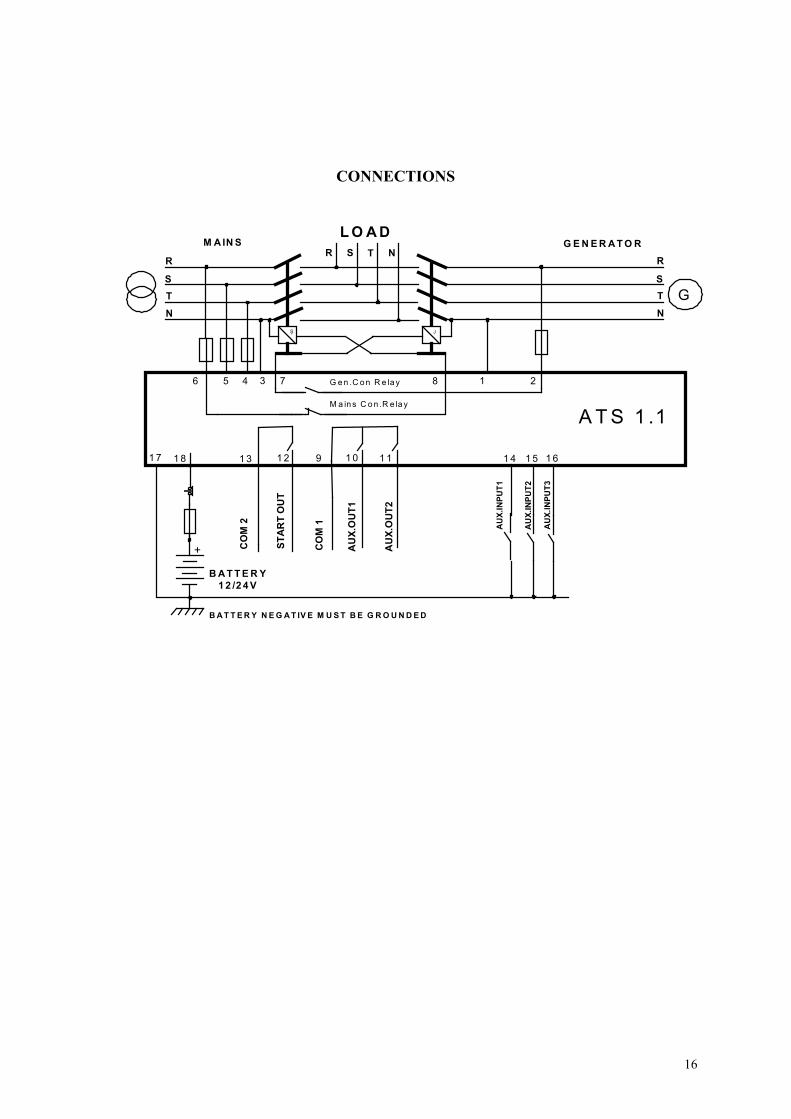
CONNECTIONS
ATS 1 .1
G en .C on R e lay
M a ins C on .R e lay
G
R
S
T
N
R
S
T
N
R S T N
GENERATORM AINS
2856 7 134
Ş J
14 15 16
AUX.INPUT1
AUX.INPUT3
AUX.INPUT2
LO AD
BATTERY N EG AT IV E M UST B E G ROUNDED
BATTERY
12 /24V
1817 12 9 11
+ COM 2
START OUT
COM 1
AUX.OUT1
AUX.OUT2
13 10


![Mesa 4 [ATS] A phase I, randomised, double blind, placebo ... · [ATS] A phase I, randomised, double blind, placebo controlled, study to assess the safety, tolerability and pharmacokine8cs](https://img.pdfslide.us/doc/110x75/5d15c00d88c993a82b8b4970/mesa-4-ats-a-phase-i-randomised-double-blind-placebo-ats-a-phase.jpg)