Embed Size (px)
Citation preview
1113141517171718
34
333
555
66
667777
8
88889910
3
6
19
20
21
21
2121222222
23
24
26
87
88
4
3
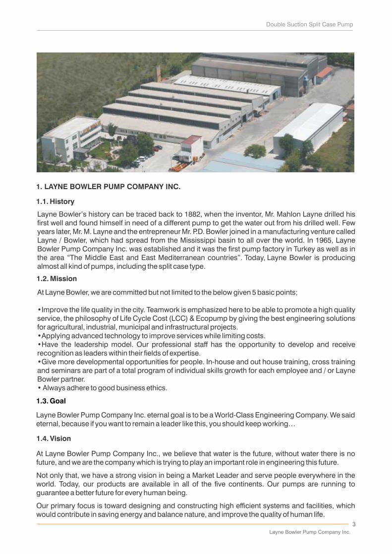
Layne Bowler’s history can be traced back to 1882, when the inventor, Mr. Mahlon Layne drilled his first well and found himself in need of a different pump to get the water out from his drilled well. Few years later, Mr. M. Layne and the entrepreneur Mr. P.D. Bowler joined in a manufacturing venture called Layne / Bowler, which had spread from the Mississippi basin to all over the world. In 1965, Layne Bowler Pump Company Inc. was established and it was the first pump factory in Turkey as well as in the area “The Middle East and East Mediterranean countries”. Today, Layne Bowler is producing almost all kind of pumps, including the split case type.
At Layne Bowler, we are committed but not limited to the below given 5 basic points;
•Improve the life quality in the city. Teamwork is emphasized here to be able to promote a high quality service, the philosophy of Life Cycle Cost (LCC) & Ecopump by giving the best engineering solutions for agricultural, industrial, municipal and infrastructural projects. •Applying advanced technology to improve services while limiting costs. •Have the leadership model. Our professional staff has the opportunity to develop and receive recognition as leaders within their fields of expertise. •Give more developmental opportunities for people. In-house and out house training, cross training and seminars are part of a total program of individual skills growth for each employee and / or Layne Bowler partner.• Always adhere to good business ethics.
Layne Bowler Pump Company Inc.
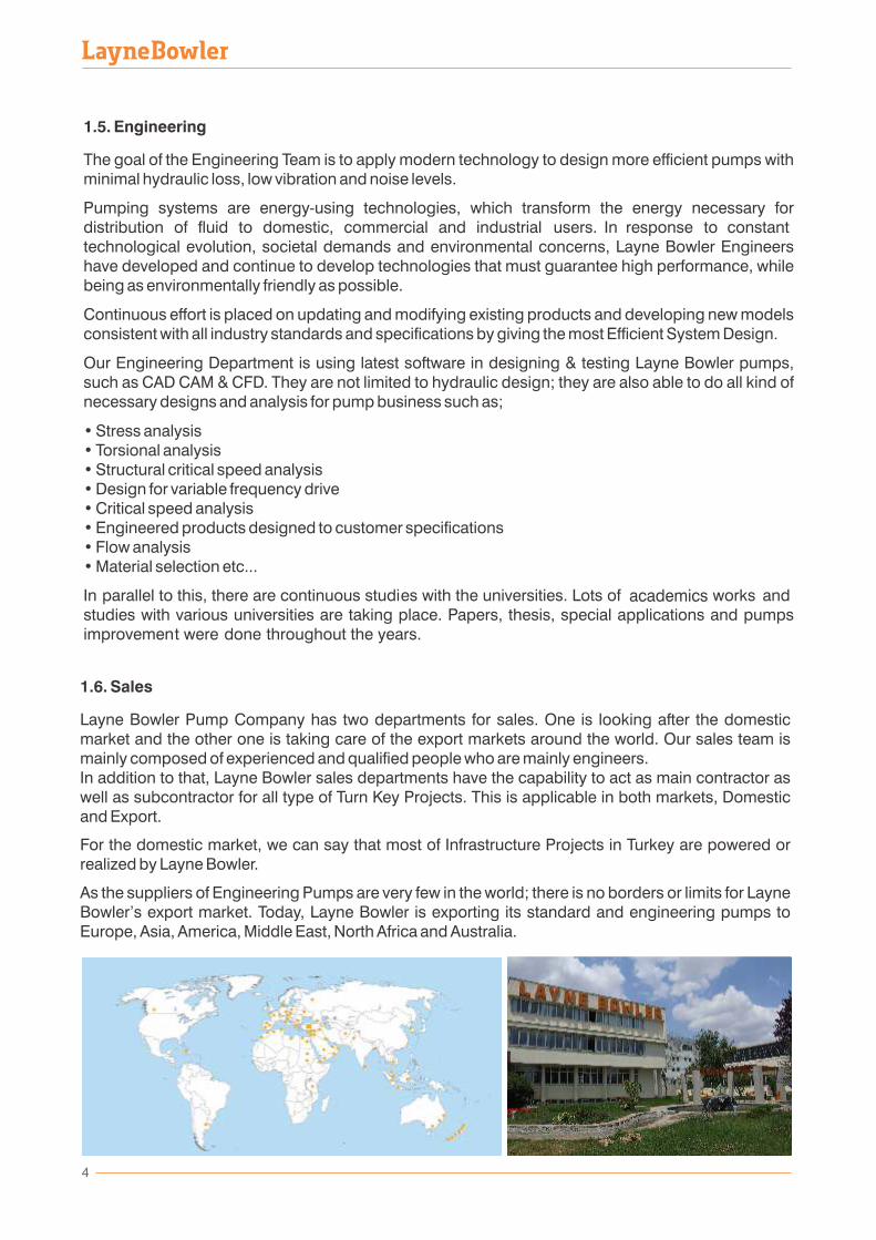
4
academics
5
Layne Bowler is supplying a distinguished After Sales Service by having;
•A special data base for every produced pump•A comprehensive stock of spare parts•Distributor network•An experienced group of technicians, supervisors and trainees, who are ready to support the distributors or the end-users everywhere in the world
by realizing & providing:
•Service & maintenance contracts•Installation contracts•Supervisor services•Troubleshooting & repair services•Warranty period servicing contrasts•Spare part supply
1.9. Quality Control
occupational health & safety management system are available.
Layne Bowler Pump Company Inc.
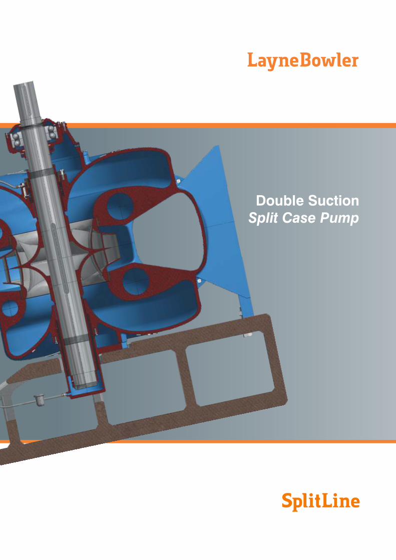
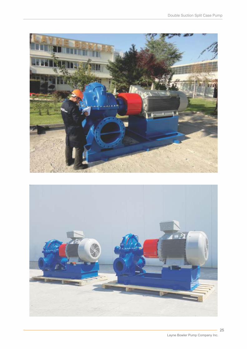
2. DOUBLE SUCTION SPLIT CASE PUMP
2.1. General
Split type (SP) pumps are radial flow pumps which have horizontal shaft, in general, splitable upper and lower casings, double suction, single or multi stage, with or without diffuser. For special applications SP pumps can be produced with vertical shaft and for high pressure.
Utilization area of split type pumps are:
• Potable water supply systems• Irrigation• Industrial water supply to factories, complexes• Sea water pumping• Closed cycles for water cleaning, water cooling, filtering, condensate pumping etc.• For pumping crude oil, petroleum products and other chemicals in chemical and petrochemical industries.
Advantages are:
• Safe working in all conditions, high head and high pressure at discharge as well as suction. • Easy and economical maintenance and repair,• Motor can be coupled to the pump from both sides,• Perfect design and modelling of casing & impeller; smooth running and low radial load are securing a high efficiency and long running life, • Vertical and horizontal applicability.
2.2. Construction
2.2.1. Casing
From the shaft level, the pump is splitable into 2 parts, the upper and lower casing. In the lower casing, the suction and discharge flanges are in opposite position and on the same axis (however different flange positions are also possible). Upper casing acts as a cover to reach inner sides of the pump and to remove rotating parts easily.
It is easy to maintain and repair the pump, only by opening the upper casing without dismantling from pipe line and chassis.
Pump rotor is lifted without using any special tool. Due to the use of elastic coupling, the rotor can be removed without moving the motor.
Wear rings protect the casing. They are fixed to lower casing to avoid their rotation with the impeller.
In case of head Hm>100 mWC, the pump casing is produced with double volute to decrease the radial load.
2 .2.2. Impeller
Impellers are produced with double entry, radial flow and double awry blades. Impellers are fixed by means of impeller lock nuts on the shaft and shaft sleeves (some models have extended sleeves). Different impeller models can be used in the same pump to widen the working range of the pump and to adapt variable working conditions. Only by changing impeller, same pump can be run in different working points.
Double suction impellers balance the hydraulic axial load just like the impellers which run in back to back arrangement.
6
2.2.3. Bearings
In general, greased type ball bearings are used when specially requested or required for some applications, journal bearings can be used. Bearing houses, which are rigidly fixed to lower body, can be removed together with the rotor, when unbolted. Bearings are protected from the pumped water by the seal and deflector.
Journal bearings can be lubricated with grease or thin clean water film (grease for bronze-stainless steel application, water lubrication for EPDM-stainless steel application).
2.2.4. Sealing
For the water leakage between pump shaft and its casing, graphite or teflon soft sealings are used. This considered as standard production, optionally or as per customer request, mechanical seals can be applied.
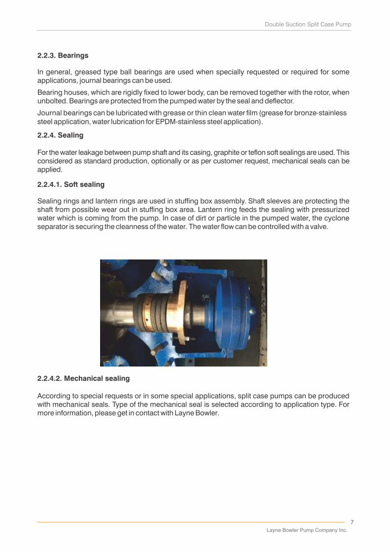
2.2.4.1. Soft sealing
Sealing rings and lantern rings are used in stuffing box assembly. Shaft sleeves are protecting the shaft from possible wear out in stuffing box area. Lantern ring feeds the sealing with pressurized water which is coming from the pump. In case of dirt or particle in the pumped water, the cyclone separator is securing the cleanness of the water. The water flow can be controlled with a valve.
2.2.4.2. Mechanical sealing
According to special requests or in some special applications, split case pumps can be produced with mechanical seals. Type of the mechanical seal is selected according to application type. For more information, please get in contact with Layne Bowler.
7
Layne Bowler Pump Company Inc.
3. INSTALLATION
3.1. Site
Pumping unit should be placed as close as possible to its pedestal. Floor space must be sufficient for installation works, inspection and maintenance. Be sure to allow for crane or hoist service.
3.2. Foundation
Foundation should be constructed according to the drawing of “Foundation Details”. If requested, static and dynamic load diagrams are supplied to customer for designing the foundation details by their own technical services according to specific standards or conditions. Foundation block must be isolated from the building according to the drawing of “Foundation Details” to prevent the affects of vibration.
Anchor bolts must be positioned and levelled according to the drawings and before grouting they must be checked properly.
3.3. Preparation for installation
Pumping units are shipped fully assembled, in some cases driving units may be assembled at jobsite. Clean the working area and remove packing of the pumping unit. Check all bolts and nuts on entire unit to make ensure secure tightening. Check all necessary bolts and nuts for foundation, chassis and couplings.
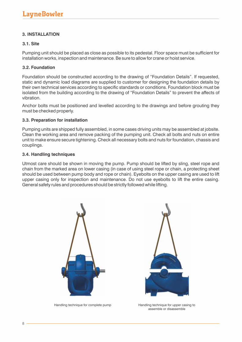
3.4. Handling techniques
Utmost care should be shown in moving the pump. Pump should be lifted by sling, steel rope and chain from the marked area on lower casing (in case of using steel rope or chain, a protecting sheet should be used between pump body and rope or chain). Eyebolts on the upper casing are used to lift upper casing only for inspection and maintenance. Do not use eyebolts to lift the entire casing. General safety rules and procedures should be strictly followed while lifting.
8
Handling technique for complete pump Handling technique for upper casing to assemble or disassemble
9
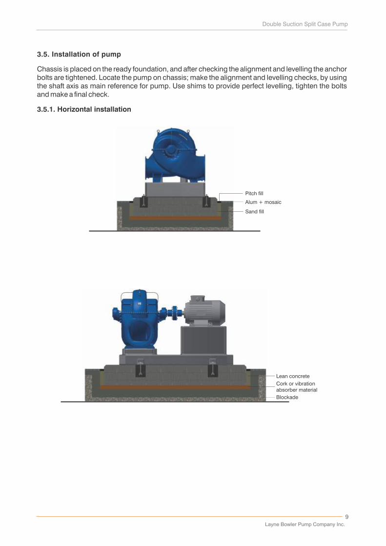
3.5. Installation of pump
Chassis is placed on the ready foundation, and after checking the alignment and levelling the anchor bolts are tightened. Locate the pump on chassis; make the alignment and levelling checks, by using the shaft axis as main reference for pump. Use shims to provide perfect levelling, tighten the bolts and make a final check.
3.5.1. Horizontal installation
Alum + mosaic
Pitch fill
Sand fill
Blockade
Lean concrete
Cork or vibrationabsorber material
Layne Bowler Pump Company Inc.
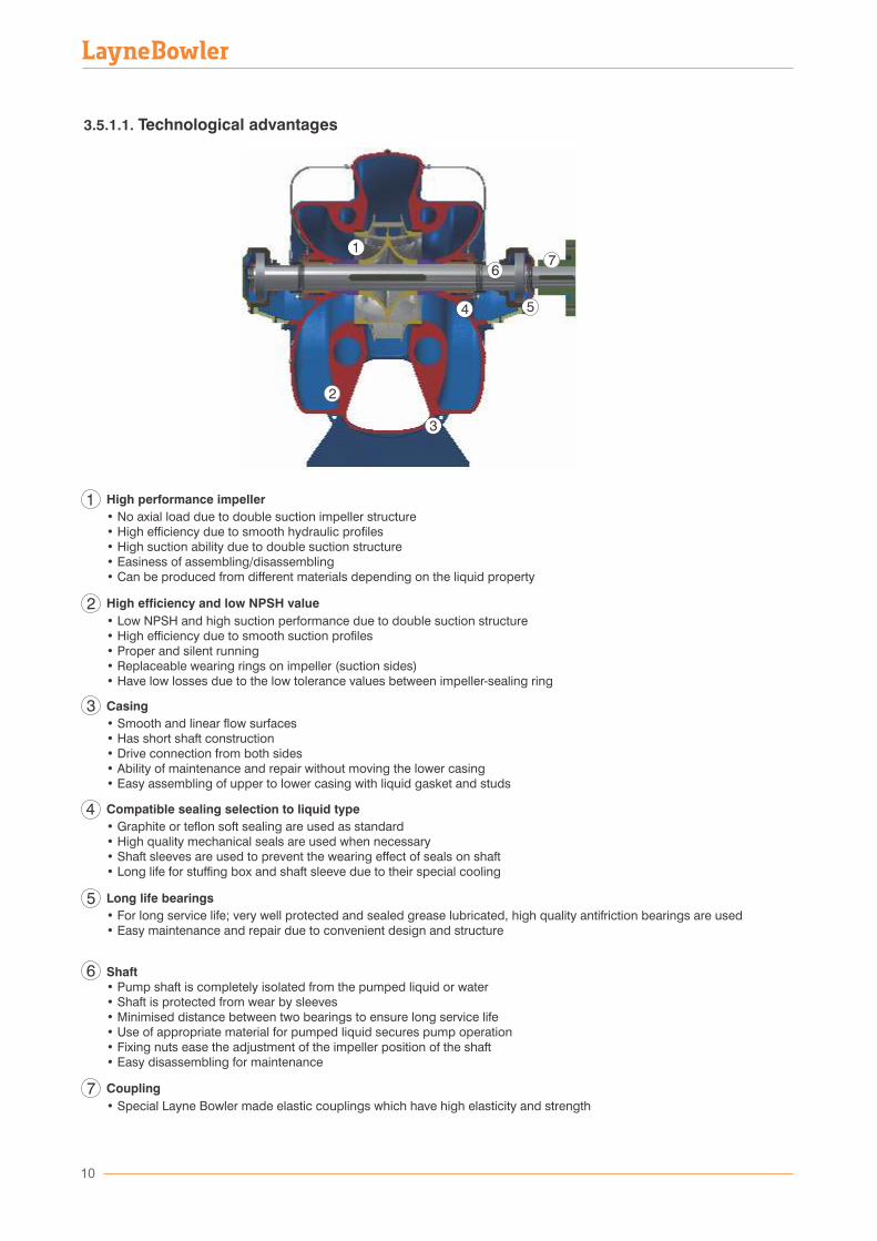
3.5.1.1. Technological advantages
10
1
2
3
4 5
76
High performance impeller
• No axial load due to double suction impeller structure• High efficiency due to smooth hydraulic profiles • High suction ability due to double suction structure• Easiness of assembling/disassembling• Can be produced from different materials depending on the liquid property
High efficiency and low NPSH value
• Low NPSH and high suction performance due to double suction structure • High efficiency due to smooth suction profiles • Proper and silent running • Replaceable wearing rings on impeller (suction sides) • Have low losses due to the low tolerance values between impeller-sealing ring
Casing
• Smooth and linear flow surfaces • Has short shaft construction • Drive connection from both sides • Ability of maintenance and repair without moving the lower casing • Easy assembling of upper to lower casing with liquid gasket and studs
Compatible sealing selection to liquid type
• Graphite or teflon soft sealing are used as standard • High quality mechanical seals are used when necessary • Shaft sleeves are used to prevent the wearing effect of seals on shaft• Long life for stuffing box and shaft sleeve due to their special cooling
Long life bearings
• For long service life; very well protected and sealed grease lubricated,• Easy maintenance and repair due to convenient design and structure
Shaft • Pump shaft is completely isolated from the pumped liquid or water • Shaft is protected from wear by sleeves • Minimised distance between two bearings to ensure long service life • Use of appropriate material for pumped liquid secures pump operation • Fixing nuts ease the adjustment of the impeller position of the shaft • Easy disassembling for maintenance
Coupling
• Special Layne Bowler made elastic couplings which have high elasticity and strength
high quality antifriction bearings are used
PART NO PART NAME MATERIALS (STANDART) MATERIALS (OPTIONAL)
1
2
3
4
6
7
8
9
10
11
12
13
14
15
18
19
20
21
22
23
24
25
26
27
28
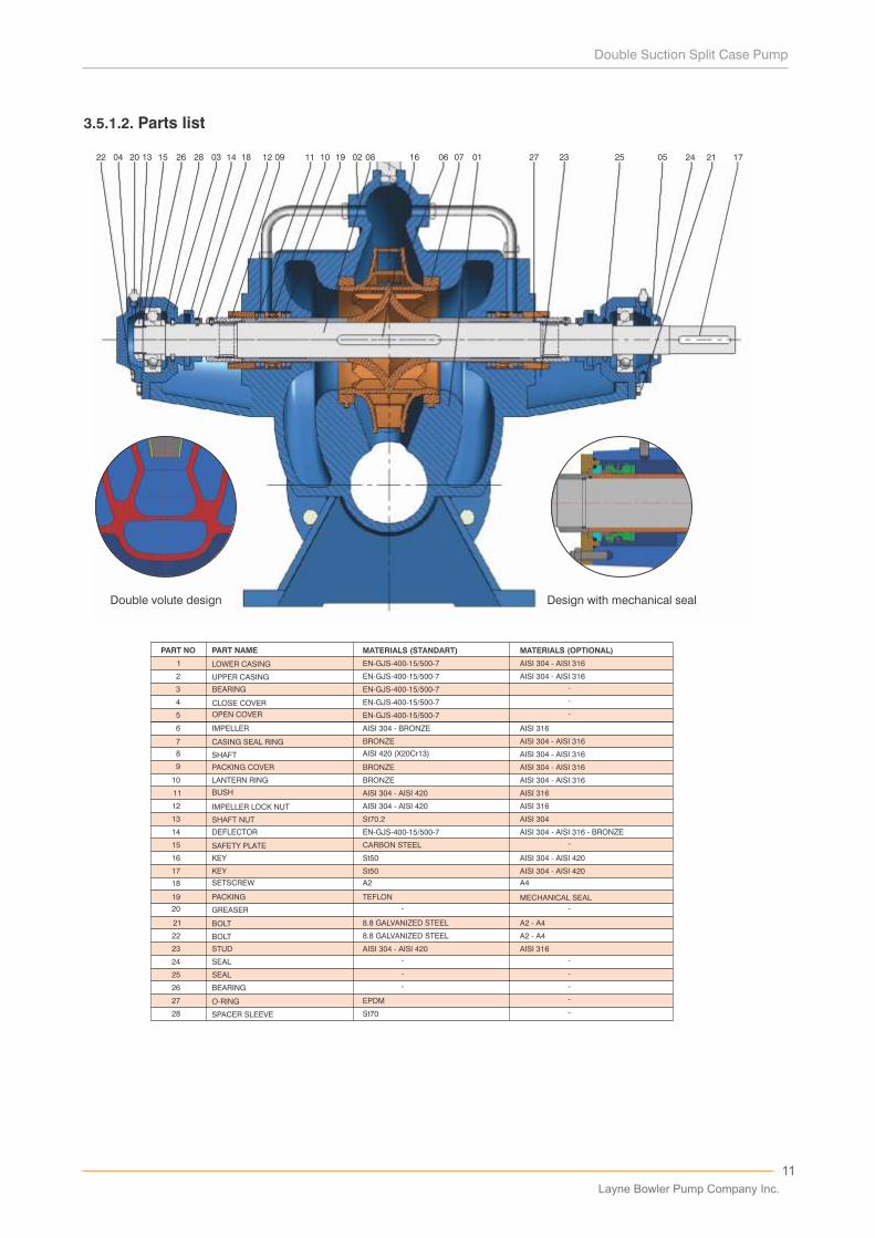
LOWER CASING
UPPER CASING
BEARING
CLOSE COVER
IMPELLER
CASING SEAL RING
SHAFT
PACKING COVER
LANTERN RING
BUSH
IMPELLER LOCK NUT
SHAFT NUT
SAFETY PLATE
SETSCREW
DEFLECTOR
PACKING
GREASER
BOLT
BOLT
STUD
SEAL
SEAL
BEARING
O-RING
SPACER SLEEVE
EN-GJS-400-15/500-7
EN-GJS-400-15/500-7
EN-GJS-400-15/500-7
EN-GJS-400-15/500-7
AISI 304 - BRONZE
BRONZE
BRONZE
BRONZE
AISI 420 (X20Cr13)
AISI 304 - AISI 420
AISI 304 - AISI 420
St70.2
CARBON STEEL
A2
EN-GJS-400-15/500-7
TEFLON
8.8 GALVANIZED STEEL
8.8 GALVANIZED STEEL
AISI 304 - AISI 420
EPDM
St70
AISI 304 - AISI 316
AISI 304 - AISI 316
-
-
-
AISI 316
AISI 304 - AISI 316
AISI 304 - AISI 316
AISI 304 - AISI 316
AISI 304 - AISI 316
AISI 316
AISI 316
AISI 304
A4
AISI 304 - AISI 316 - BRONZE
MECHANICAL SEAL
--
-
-
-
-
-
-
-
-
A2 - A4
A2 - A4
AISI 316
5 OPEN COVER EN-GJS-400-15/500-7 -
16
17
KEY
KEY
St50
St50
AISI 304 - AISI 420
AISI 304 - AISI 420
Design with mechanical sealDouble volute design
22 04 20 13 15 26 28 03 14 18 12 09 11 10 19 02 08 16 06 07 01 27 23 25 05 24 21 17
3.5.1.2. Parts list
11
Layne Bowler Pump Company Inc.
12
13
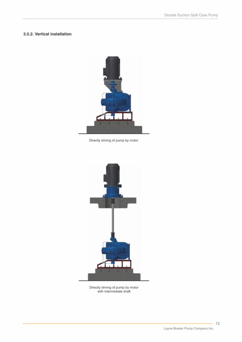
3.5.2. Vertical installation
Directly driving of pump by motor
Directly driving of pump by motorwith intermediate shaft
Layne Bowler Pump Company Inc.
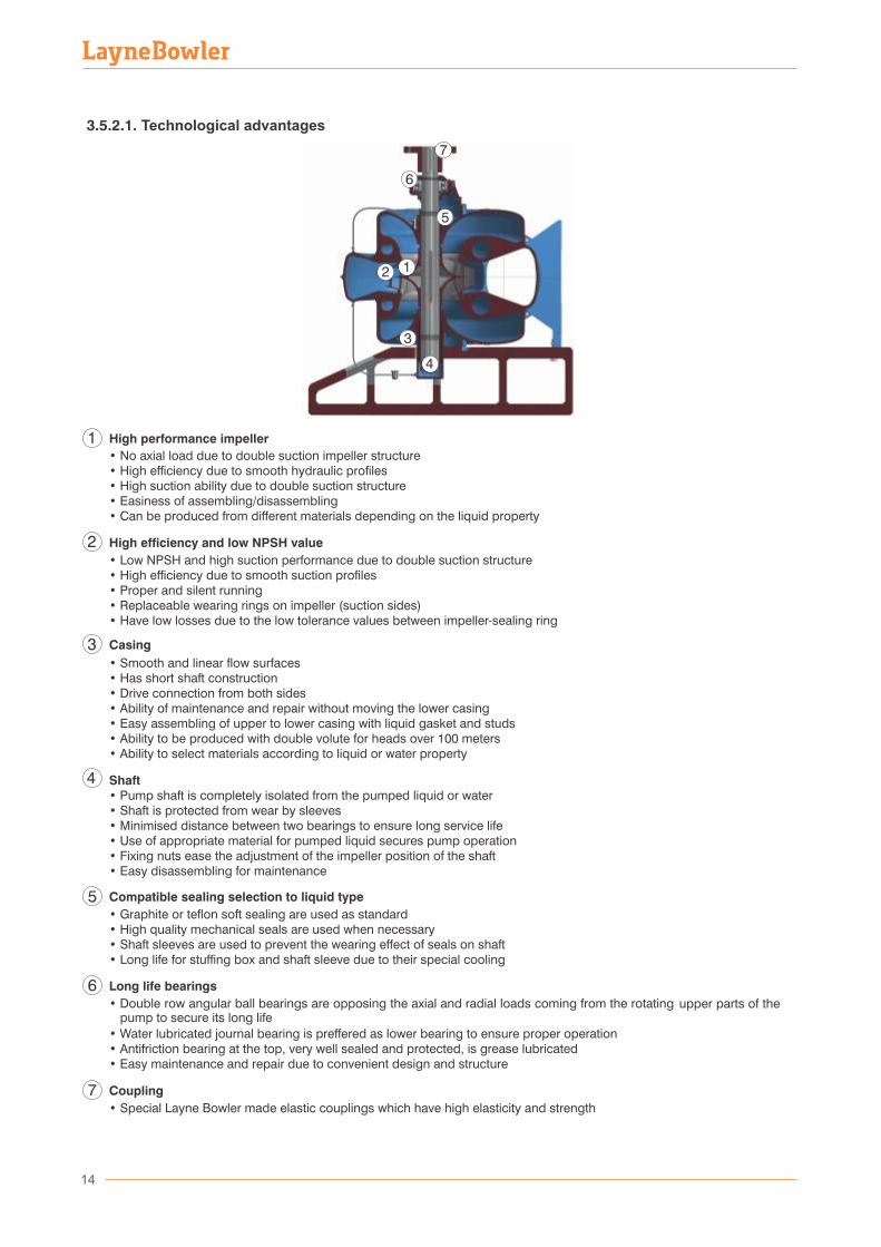
High performance impeller • No axial load due to double suction impeller structure • High efficiency due to smooth hydraulic profiles • High suction ability due to double suction structure • Easiness of assembling/disassembling • Can be produced from different materials depending on the liquid property
High efficiency and low NPSH value • Low NPSH and high suction performance due to double suction structure • High efficiency due to smooth suction profiles
• Proper and silent running• Replaceable wearing rings on impeller (suction sides)• Have low losses due to the low tolerance values between impeller-sealing ring
Casing
• Smooth and linear flow surfaces• Has short shaft construction• Drive connection from both sides• Ability of maintenance and repair without moving the lower casing
• Easy assembling of upper to lower casing with liquid gasket and studs• Ability to be produced with double volute for heads over 100 meters• Ability to select materials according to liquid or water property
Shaft• Pump shaft is completely isolated from the pumped liquid or water• Shaft is protected from wear by sleeves• Minimised distance between two bearings to ensure long service life• Use of appropriate material for pumped liquid secures pump operation• Fixing nuts ease the adjustment of the impeller position of the shaft • Easy disassembling for maintenance
Compatible sealing selection to liquid type
• Graphite or teflon soft sealing are used as standard• High quality mechanical seals are used when necessary• Shaft sleeves are used to prevent the wearing effect of seals on shaft• Long life for stuffing box and shaft sleeve due to their special cooling
Long life bearings
• Double row angular ball bearings are opposing the axial and radial loads coming from the rotating
• Water lubricated journal bearing is preffered as lower bearing to ensure proper operation• Antifriction bearing at the top, very well sealed and protected, is grease lubricated• Easy maintenance and repair due to convenient design and structure
Coupling
• Special Layne Bowler made elastic couplings which have high elasticity and strength
14
3.5.2.1. Technological advantages
7
6
7
upper parts of the pump to secure its long life
15
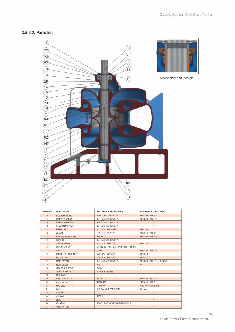
3.5.2.2. Parts list
PART NO PART NAME MATERIALS (STANDART) MATERIALS (OPTIONAL)
1
2
3
4
5
6
7
8
9
10
11
12
13
14
15
16
17
18
19
20
21
22
23
24
25
26
27
LOWER CASING
UPPER CASING
UPPER BEARING
LOWER BEARING
IMPELLER
CASING SEAL RING
COVER
SHAFT BUSH
BEARING BUSH
KEY
IMPELLER LOCK NUT
SHAFT NUT
DEFLECTOR
SETSCREW
SPACER SLEEVE
SAFETY PLATE
BEARING
LANTERN RING
PACKING COVER
PACKING
BOLT
GREASER
O-RING
SEAL
CHASSIS
SEPARATOR
EN-GJS-400-15/500-7
EN-GJS-400-15/500-7
EN-GJS-400-15/500-7
EN-GJS-400-15/500-7
AISI 304 - BRONZE
BRONZE
EN-GJS-400-15/500-7
AISI 304 - AISI 420
(AISI 304 - AISI 420 - BRONZE) + EPDM
St50
AISI 304 - AISI 420
AISI 304 - AISI 420
EN-GJS-400-15/500-7
A2
St70
CARBON STEEL
-
-
-
-
BRONZE
BRONZE
TEFLON
8.8 GALVANIZED STEEL
EPDM
EN-GJS-400-15/500-7/GG25/St37.2
AISI 304 - AISI 316
AISI 304 - AISI 316
-
-
-
-
-
-
-
A4
AISI 316
AISI 304 - AISI 316
AISI 304 - AISI 316
AISI 316
AISI 304 - AISI 420
AISI 316
AISI 316
AISI 304 - AISI 316 - BRONZE
AISI 304 - AISI 316
AISI 304 - AISI 316
-
-
-
-
-
MECHANICAL SEAL
A2 - A4
SHAFT AISI 420 (X20Cr13)
17
22
23
03
18
16
25
14
15
12
20
19
21
09
01
11
02
05
07
06
15
24
09
10
27
22
26
04
15
13
11
25
08
22
13 Mechanical seal design
Layne Bowler Pump Company Inc.
16
3.6. Coupling pump and motor
Place the motor on chassis in accordance with the installation drawings. Do the levelling and alignment of the
motor shaft axis according to pump shaft axis. For a proper alignment and levelling use the techniques given
in section 3.9. After this control, tighten the bolts for motor-chassis mounting.
3.7. Preparation of stuffing box
Pumping units are shipped together with packed stuffing boxes. In case of long storage periods, soft packing
should be renewed before first commissioning. The pumps which are dispatched from factory without
connecting the sealing or sealing cooling system (in some cases, stuffing boxes can be sent as disassembled
to avoid unwanted damages during shipment), has to be assembled or fixed at its final destination or site and
controlled before start up.
When the pumps are furnished with mechanical seals, the seals are installed and adjusted at factory before
shipment. To protect the mechanical seal during transportation, extra fixtures are used to prevent the axial
movement of the shaft; these fixtures must be removed during installation at site. To prepare the seal for
operation, flush lines (if any) dispatched separately from main body, must be connected in accordance with
the manufacturer's specifications. Installation drawings are attached to the pump and should be filed for
future use to adjust the seal when the pump is disassembled. Please keep the drawing and the user manual
of the mechanical seal to do maintenance accordingly.
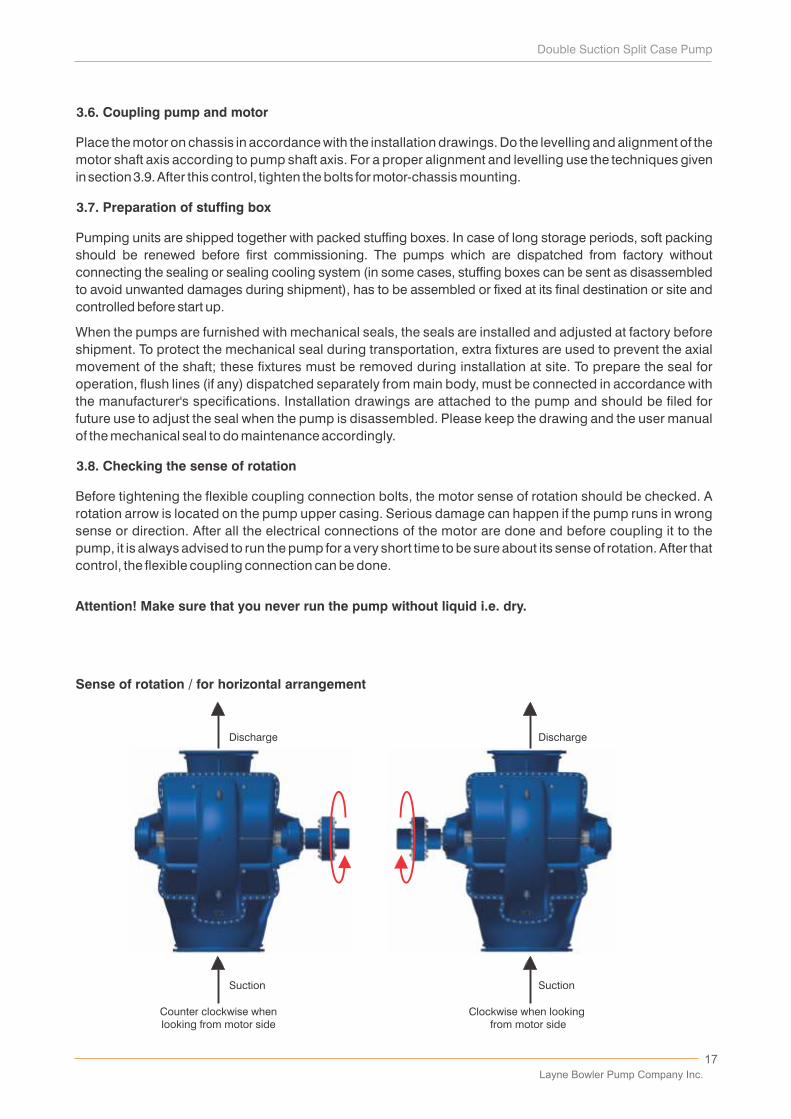
3.8. Checking the sense of rotation
Before tightening the flexible coupling connection bolts, the motor sense of rotation should be checked. A
rotation arrow is located on the pump upper casing. Serious damage can happen if the pump runs in wrong
sense or direction. After all the electrical connections of the motor are done and before coupling it to the
pump, it is always advised to run the pump for a very short time to be sure about its sense of rotation. After that
control, the flexible coupling connection can be done.
Attention! Make sure that you never run the pump without liquid i.e. dry.
17
Sense of rotation / for horizontal arrangement
Suction
Discharge
Counter clockwise whenlooking from motor side
Suction
Discharge
Clockwise when looking from motor side
Layne Bowler Pump Company Inc.
18
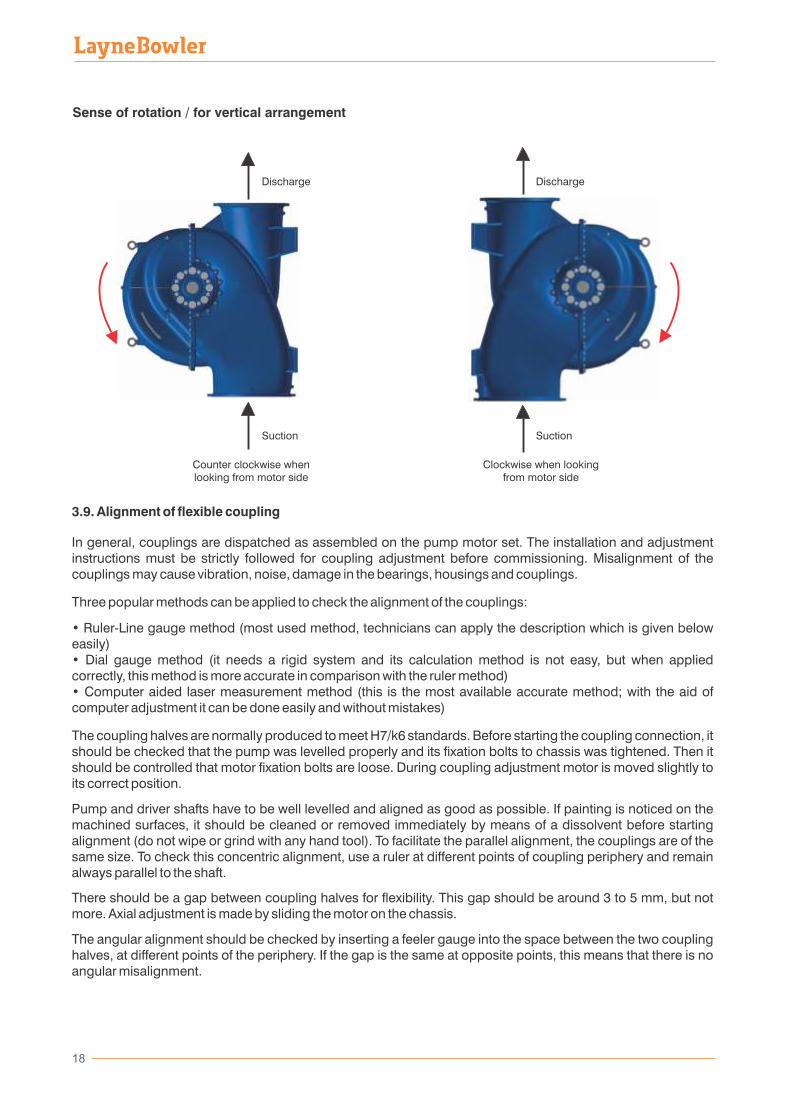
Sense of rotation / for vertical arrangement
3.9. Alignment of flexible coupling
In general, couplings are dispatched as assembled on the pump motor set. The installation and adjustment instructions must be strictly followed for coupling adjustment before commissioning. Misalignment of the couplings may cause vibration, noise, damage in the bearings, housings and couplings.
Three popular methods can be applied to check the alignment of the couplings:
• Ruler-Line gauge method (most used method, technicians can apply the description which is given below easily)• Dial gauge method (it needs a rigid system and its calculation method is not easy, but when applied correctly, this method is more accurate in comparison with the ruler method)• Computer aided laser measurement method (this is the most available accurate method; with the aid of computer adjustment it can be done easily and without mistakes)
The coupling halves are normally produced to meet H7/k6 standards. Before starting the coupling connection, it should be checked that the pump was levelled properly and its fixation bolts to chassis was tightened. Then it should be controlled that motor fixation bolts are loose. During coupling adjustment motor is moved slightly to its correct position.
Pump and driver shafts have to be well levelled and aligned as good as possible. If painting is noticed on the machined surfaces, it should be cleaned or removed immediately by means of a dissolvent before starting alignment (do not wipe or grind with any hand tool). To facilitate the parallel alignment, the couplings are of the same size. To check this concentric alignment, use a ruler at different points of coupling periphery and remain always parallel to the shaft.
There should be a gap between coupling halves for flexibility. This gap should be around 3 to 5 mm, but not more. Axial adjustment is made by sliding the motor on the chassis.
The angular alignment should be checked by inserting a feeler gauge into the space between the two coupling halves, at different points of the periphery. If the gap is the same at opposite points, this means that there is no angular misalignment.
Clockwise when lookingfrom motor side
Discharge
Suction
Discharge
Suction
Counter clockwise whenlooking from motor side
19
After final fixation of motor bolts, alignment has to be checked once more and then bearings rubbers or cushions are inserted then the special coupling bolts and nuts are firmly tightened. Before this, sense of rotation should be checked as per section 3.8.
Before running the pump set, be sure that the coupling guard is installed.
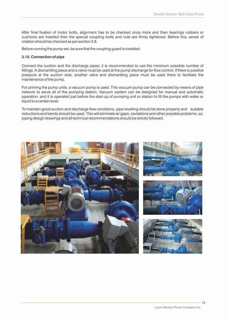
3.10. Connection of pipe
Connect the suction and the discharge pipes; it is recommended to use the minimum possible number of fittings. A dismantling piece and a valve must be used at the pump discharge for flow control. If there is positive pressure at the suction side, another valve and dismantling piece must be used there to facilitate the maintenance of the pump.
For priming the pump units, a vacuum pump is used. This vacuum pump can be connected by means of pipe network to serve all of the pumping station. Vacuum system can be designed for manual and automatic operation, and it is operated just before the start-up of pumping unit or station to fill the pumps with water or liquid to a certain level.
To maintain good suction and discharge flow conditions, pipe levelling should be done properly and suitable reductions and bends should be used. This will eliminate air gaps, cavitations and other possible problems, so, piping design drawings and all technical recommendations should be strictly followed.
Layne Bowler Pump Company Inc.
• All centrifugal pumps should be started up with closed discharge valve.
• Before stopping the pump, first close the valve on the discharge line, then stop the pump.
• In case of positive suction head, make sure that the suction valve is completely open.
• In case of negative suction head, make sure that no air gaps in the pump body.
• Make sure that water is coming from stuffing when the pump is running. Adjust the quantity of water as
you wish by using the valve on stuffing cooling pipe.0• Stop the pump in case the temperature of pump bearings increases over 80 C.
• Follow up the current and power values of the motor from the control panel. If the readings are
exceeding motor label values, please stop the pump.
• In case of availability of stand-by pumps in a station, run each of them in sequences of 8 hours.
• Do not run the pump more than 2 minutes with closed valve.
• Check the manometer at the discharge of pump to see whether the pump is running at its working point
or not.
• For negative suction pumps, make sure that water level value of suction tank does not drop below its
calculated minimum value.
• For positive suction pumps, by mean of manometer, make sure that pressure value in suction pipe does
not to drop below calculated minimum pressure value.
• In case of pump noise and vibration, please stop the pump. Check the flexible coupling and
the connections of the pump on its chassis. Re-align the flexible coupling if needed.
• If you want to decrease the pump capacity of the temporarily, throttle or reduce the discharge valve.
• It is never allowed to adjust the discharge rate from the suction valve.
• In order not to damage the electrical motor, make sure that the voltage stays in the range of ±5% of the
nominal voltage.
• To determine the sense of rotation of the pump, do not start up the electrical motor before vacuuming.
• Do not run the pump dry even for determination of the sense of rotation.
• After running the pump for 4000 hours, change the oil of the bearings completely. Wash the bearings
with solvent, fill them with grease and reinstall. After that fill the new oil into pump bearing house.
Overfilling of oil causes overheating on the bearings. The recommended oil is “Shell Alvania R3” or its
equivalent.
• Change the gland packing of the pump when the packing boxed cover is squeezed up to the thickness
of one unwrapped ring of packing. Joints of every twist should be misaligned. Recommended standard
soft sealing material is “Teflon”.
• Make sure that the water outlets of sealing are not clogged. Otherwise water will go the bearings. Stop
the pump if the evacuation pipe is blocked. Do not re-run the pump before cleaning it.
• For inoperative pumps, especially during winter time, avoid freezing of the water in the pump. For that,
drain the water out from the pump by opening the plugs under the suction and discharge. This emptying
operation should be done with closed suction and discharge valves.
• To open the upper casing of the pump, first, turn off the suction and the discharge valves. Then open the
plugs under the suction and the discharge ends. When water stop to come from these plugs, this means
that there is no leakage from the suction or the discharge valves and the upper casing of the pump can be
opened.
• For new pump installation, strengthen the chassis by filling concrete into it and follow all the notes given
in the technical drawing for the basement.
• If vibration value of pump-motor bearing is read-out over 4 mm/sec for horizontal pump and 7 mm/sec
for vertical pump, please stop the pump set immediately and do the necessary controls to find out the
reason of high vibration. Usually, such a vibration is due to misalignment on the pump flexible coupling
or because of un-tightened bolts on chassis.
• The pump should be running according to the values written on its name plate. Otherwise, please get in
touch with factory.
20
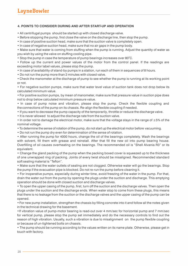
4. POINTS TO CONSIDER DURING AND AFTER START-UP AND OPERATION
21
5. MAINTENANCE AND REPAIR
To remove the upper casing of the pump for inspection or maintenance the below items should be followed:
• Disconnect the drive from power supply and take all precautions to avoid unwanted run of the pump during dismantling operation.• Close all the valves.• Remove the coupling screws.• If needed, disassemble the sealing water feeding pipes, bearing lubricator pipes, manometer etc. • Remove the gland packing.• Remove the bolts holding the upper casing.• Locate and tight the eyebolts for hoisting or lifting the upper casing.• Remove the upper casing by lifting from the eyebolts.
For the disassembly of the rotating elements proceed as follows:
• Remove the bolts holding the bearing housing and the housing body together.• Remove the complete rotor by lifting with sling.• Do not lay the shaft-impeller-bearings assembly down on the floor which may cause damage.
6. OPERATIONAL PROBLEMS AND SOLUTIONS FOR PUMPS
6.1. Insufficient discharge
• The gap between the impeller and sealing ring might be over the acceptable limits. For that reason change the sealing ring.• Manometric head value might be over the value written on the pump name plate. If the motor power is enough, use another impeller with bigger diameter.• Impurities or unwanted particle might enter the pump. Open the upper casing and clean inside the pump as well as the impeller.• Air might accumulate in the pump. In such case, first stop the pump, then evacuate the air and re-run the pump• If there is strainer or foot valve in suction side and there is a flow problem, please make sure that no dirt is accumulated and clog them.• The valve in pump suction side might be closed or semi-closed. Make sure that the valve is open.• Suction head value might be over the allowable suction head value. For that reason, wait until getting the designed or appropriate water level.• Impeller might be broken and need to be changed.
6.2. No discharge
The valve in pump suction side might be closed. Make sure that the valve is open.• • Air might accumulate in the pump. In such case, first stop the pump, then evacuate the air and re-run the pump.• Manometric head value at closed valve is higher than the value given during the pump factory test. This will lead to air chambers inside the pump. To solve this problem, please empty the water in the discharge line until the closed valve value go down below the known test value. • Alter the motor electrical connections, if the pump is operating in reverse direction.• If there is strainer or foot valve in suction side and there is a flow problem, please make sure that no dirt is accumulated and clog them. • Site suction head dropped below the allowable or design suction head value. In this case, please wait until the suction head increase to it requested value.• Check if the used pipes at the pump discharge are obeying the hydraulic rules or not. Pipe diameter and pressure class should be according or suitable to the pump. • Impeller might be broken and need to be changed.
Layne Bowler Pump Company Inc.
22
6.3. Pump efficiency under its label value
• If the pump is not giving the requested or designed pressure head, please adjust the valve at the discharge by opening or closing it until getting the necessary head value. If it is not possible to get the designed value, you must get in touch with the factory to check or learn the impeller diameter. • Mechanical problem might occur in the pump. So first stop the pump and inspect. Problem can be due to impeller, sealing rings or due unwanted particles in the pump or impeller. It can also depend on a broken bearing or misalignment of flexible coupling, etc... • In case of cavitation, stop the pump and search for the reason behind. This can be due to a suction heap drop below the allowable or design suction value, because of air entered the pump from the suction equipment, some dirt or particles stuck in the strainer or foot valve at suction side or a change in the pumped liquid temperature. • The space or gap between the impeller and the sealing ring might be over its required value; this will lead to losses in capacity and decrease in efficiency. In such a case, please change the sealing ring.• Low efficiency can be due to the measurement tools; to avoid that all measurement devices should be calibrated.• Impeller might be broken and need to be changed.
6.4. Excessive power consumption
• Manometric head value might be under the value written on the pump name plate. Please note that for centrifugal and semi-centrifugal impellers; pumps absorb more power when the head value is lower than its designed one; however it is the opposite case for mixed flow and propeller impellers.• It can be due to cavitation; therefore stop the pump and follow the previous notes to find the reason.• Mechanical problem might occur in the pump. So first stop the pump and inspect. Problem can be due to impeller, sealing rings or due unwanted particles in the pump or impeller. It can also depend on a broken bearing or misalignment of flexible coupling, etc. • Density of the pumped liquid might be high. Check the density of liquid as well as its viscosity.• Sealing of pump might be over tightened. Please stop the pump and check.• Sealing might not getting enough water. Stop the pump and find the way to get the necessary water. • There might be problem in the motor connection to power supply; please check.
6.5. Abnormal or excessive noise
• In case of cavitation, stop the pump and follow the previous notes to solve the problem.• Misalignment in the flexible pump-motor coupling. Stop the pump and follow the previous notes to correct it.• Foreign object might entered into the pump. Please check by disassembling the upper casing.• Pump bearings might be broken. Check the bearings and change them if necessary.•A part of the pump impeller might be broken which is causing an excessive noise while the pump is running. Replace the pump impeller with a new one.
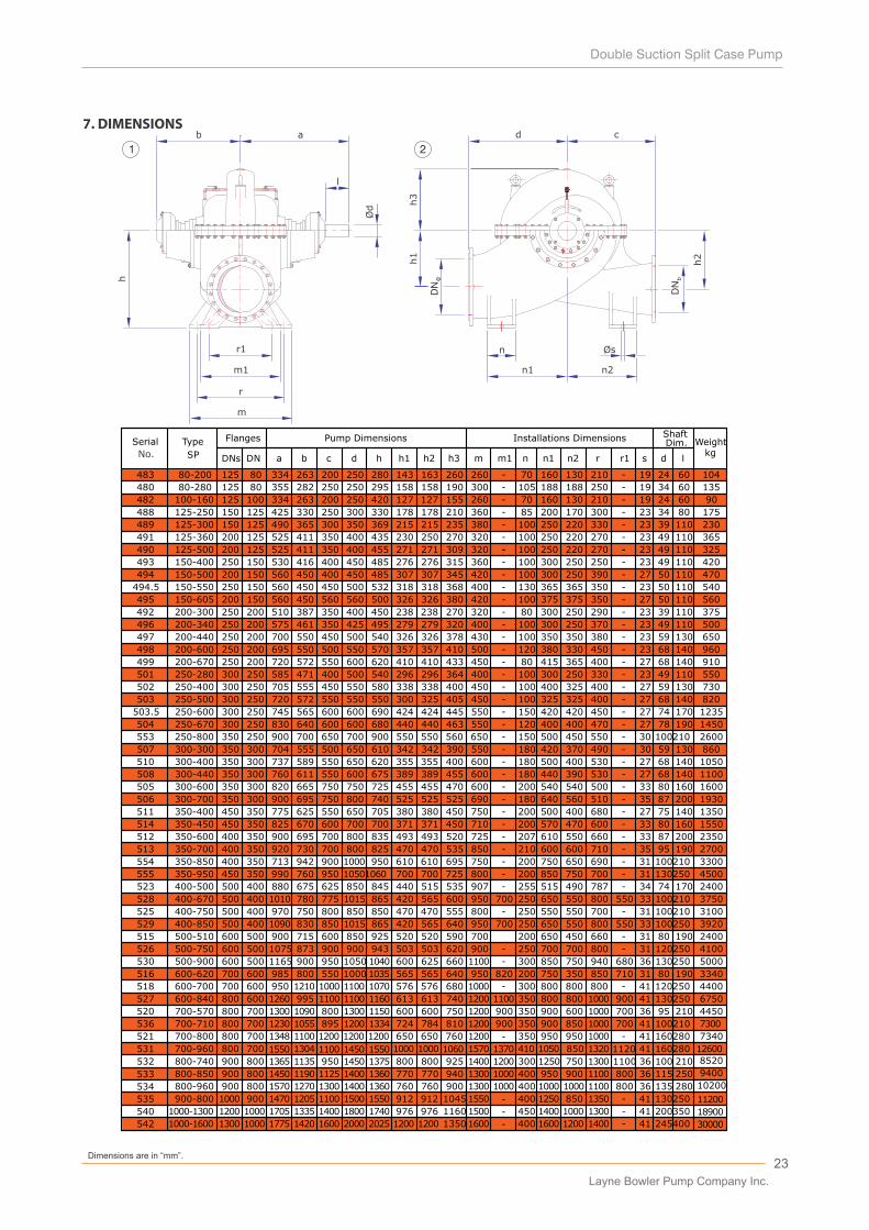
7. DIMENSIONS
Øs
h3
h1
m1
r
r1
h
b a
ı
Ød
d c
n
n1 n2
h2
1 2
23D�mens�ons are �n “mm”.
a b c d h h1 h2 h3 m m1 n n1 n2 r r1 s d l
80-200 125 80 334 263 200 250 280 143 163 260 -260 70 160 130 210 - 19 24 60
-
-
-
-
--
-
-
-
-
-
-
-
-
-
-
-
-
-
-
-
-
-
--
-
-
-
-
-
-
-
-
-
-
-
-
483
488 125-250 150 125 425 330 250 300 330 178 178 210 360 85 200 170 300 23 34 80
125-300 150 125489 490 365 300 350 369 215 215 235 380 100 250 220 330 23 39 110
490 125-500 200 125 525 411 350 400 455 271 271 309 320 100 220250 270 23 49 110
491 125-360 200 125 525 411 350 400 435 230 250 270 320 100 250 220 270 23 49 110
150-400 250 150 530 416 400 450 485 276 276 315 360 - 300 250 250 - 23 49 110
494 150-500 200 150 560 450 400 450 485 307 307 345 420 300100 250 390 27 50 110
495 150-605 200 150 560 450 560 560 500 326 326 380 420 100 375 375 350 27 50 110
496 200-340 250 200 575 461 350 425 495 279 279 320 400 100 300 250 370 23 49 110
497 200-440 250 200 700 550 450 500 540 326 326 378 430 100 350 350 380 23 59 130
498 200-600 200250 695 550 500 550 570 357 357 410 500 120 380 330 450 23 68 140
200-670 250 200 720 572 550 600 620 410 410 433 450 80 415 365 400 27 68 140
501 250-280 300 250 585 471 400 500 540 296 296 364 400 100 300 250 330 23 49 110
502 250-400 250300 705 555 450 550 580 338 338 400 450 100 400 325 400 27 59 130
503 250-500 300 250 720 572 550 550 550 300 325 405 450 100 325 325 400 27 68 140
503.5 250-600 300 250 745 565 600 600 690 424 424 445 550 150 420 420 450 27 74 170
250-670 250300 830 640 600 600 680 440 440 463 550 120 400 400 470 27 78 190
507 300-300 350 300 704 555 500 650 610 342 342 390 550 180 420 370 490 30 59 130
508 300-440 350 300 760 611 550 600 675 389 389 455 600 180 440 390 530 27 68 140-
-
-
-
-
-
-
-
-
505 300-600 350 300 820 665 750 750 725 455 455 470 600 200 540 540 500 33 80 160
300-700 350 300 900 695 750 800 740 525 525 525 690 180 640 560 510 35 87 200
300-400
350-400
512 350-600 350400 900 695 700 800 835 493 493 520 725 207 610 550 660 33 87 200
400 350350-700 920 730 700 800 825 470 470 535 850 210 600 600 710 35 95 190
523 400-500 500 400 880 675 625 850 845 440 515 535 907 255 515 490 787 34 74 170
400-670 500 400528 1010 780 775 1015 865 420 565 600 950 700 250 650 550 800 550 33 100210
529 400-850 500 400 1090 830 850 1015 865 420 565 640 950 700 250 650 550 800 550 33 100250
500-750 600 500 1075 873 900 503 503 620 900 250 700 700 800 31 120250
530 500-900 600 500 1165 900 950 1050 1040 600 625 660 1100 300 850 750 940 680 36 130250
516 600-620 700 600 985 800 550 1000 1035 565 565 640 950 200 750 350 850 31 80 190
600-840 800 600 1260 1100 1100 1160 613 613 740 1200 350 800 800 1000 900 41 130250
700-570 800 700 1300 1090 800 1300 1150 600 600 750 1200 900 350 900 600 1000 700 36 95 210
536 700-710 800 700 1230 1055 895 1200 1334 724 784 810 1200 900 350 900 850 1000 700 41 100210
531
532 800-740
800-850
800-960
900 800
800900
800900
1365
1450
1570
1135
1190
1270
950
1125
1300
1450
1400
1400
1375
1360
1360
800
770
760
800
770
760
925
940
900
1400
1300
1300
1200
1000
1000
300
400
400
1250
950
1000
750
900
1000
1100
800
800
36
36
36
100
115
135
210
250
280
493 100
525 400-750
526
515
900 943 - -
-
527 995 1100
500 400 970 750 800 850 850 470 470 555 800 - 250 550 550 700 - 31 100210
500-510
499
504
506
482 100-160 125 100 334 263 200 250 420 127 127 155 260 70 160 130 210 19 24 60
535 900-800 1000 900 1470 1205 1100 1500 1550 912 912 1045 1550 - 400 1250 850 1350 - 41 130250
- -
510
511
513
518
520
521
533
534
104
175
230
365
325
420
470
560
500
650
550
730
820
1235
1450
860
1100
1600
1930
2350
2400
3750
3100
3920
5000
3340
6750
8520
11200
90
960
910
2700
4100
4450
7300
9400
10200
-494.5 150-550 250 150 560 450 450 500 532 318 318 368 400 130 365 365 350 - 23 50 110 540
480 80-280 125 80 355 282 250 250 295 158 158 190 300 - 105 188 188 250 - 19 34 60
700-800
41 1602801320 11208501050410137015701060100010001550145011001550800 700700-960
135
514 350-450
350 300 737 589 550 650 620 355 355 400 600 - 180 500 400 530 - 27 68 140 1050
450 350 775 625 550 650 705 380 380 450 750 - 200 500 400 -680 27 75 140 1350
450 350 825 670 600 700 700 371 371 450 710 - 200 570 470 600 - 33 80 160 1550
600 500 900 715 600 850 925 520 520 590 700 200 650 450 660 - 31 80 190 2400
800 700 1348
1304
1100 1200 1200 1200 650 650 760 1200 - 350 950 950 1000 - 41 160280 7340
12600
540
542
1000-1300 1200 1000 1705 1335 1400 1800 1740 976 976 1160 1500 - 450 1400 1000 1300 - 41 200350
1000-1600 1300 1000 1775 1420 1600 2000 2025 1200 1200 1350 1600 - 400 1600 1200 1400 - 41 245400
18900
30000
600-700 700 600 950 1210 1000 1100 1070 576 576 680 1000 - 300 800 800 800 - 41 120250 4400
820 710
492
554
200-300 250 200 510 387 350 400 450 238 238 270 320 - 80 300 250 290 - 23 39 110
350-850 400 350 713 942 900 1000 950 610 610 695 750 - 200 750 650 690 - 31 100210 3300
DNs
Serial
DN
Type
SP
Pump Dimensions Installations DimensionsDim.Shaft
Weightkg
Flanges
375
553 250-800 350 250 900 700 650 700 900 550 550 560 650 - 150 500 450 550 - 30 2600
555 350-950 450 350 990 760 950 10501060 700 700 725 800 - 200 850 750 700 - 31 4500
100210
130250
1300
1100
1100
m
No.
Layne Bowler Pump Company Inc.
SP1000-1600
SP1000-1300
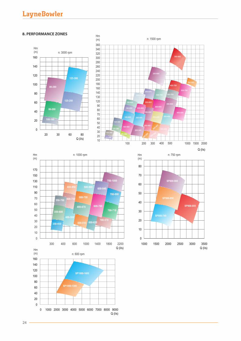
Hm(m) n: 600 rpm
160
140
120
100
80
60
40
20
0
0 1000 2000 3000 4000 5000 6000 7000 8000 9000Q (l/s)
Hm(m)
SP800-960
SP800-850
SP900-800
SP800-740
700-1000
600-840500-900400-850
400-750350-700
350-600
350-450
400-500
500-510
400-670
500-750
600-700
600-620700-570
700-800
700-710
n: 1000 rpmHm(m)
170
150
130
110
90
70
60
50
40
30
20
10
0
1000 1400 1800 2200
Q (l/s)
300 400 600
80
70
60
50
40
30
20
10
0
1000
n: 750 rpm
Q (l/s)
1500 2000 2500 3000 3500
125-300
125-250
80-200
100-160
80-280
n: 3000 rpm
160
140
120
100
80
60
40
20
0
Hm(m)
Q (l/s)
20 30 60 80
8. PERFORMANCE ZONES
24
100 200 50040010
300 1000
20
30
40
50
60
70
80
90
120
130
140
160
180
1500
200
2000
220
240
320
300
340
280
260
360
150-400
125-500
150-500
150-605
200-340
200-440
200-670
200-600
250-
280
250-400
250-500
250-600
250-670
300-300
300-440
300-600
300-700
350-450
350-600
350-700
350-400
150-300
125-360
400-500
400-750
500-750
500-900
150-550
125-250
125-300
300-
400
250-800
350-950
Hm(m)
Q (l/s)
n: 1500 rpm
25
Layne Bowler Pump Company Inc.
Performance Curves
3000rpm
1500rpm
1000rpm
750rpm
600rpm
27
Layne Bowler Pump Company Inc.

28
B = Ø 190
A = Ø 215
C = Ø 165
0 m
20°C31g/cm
D�scharge D�ameter
Pump We�ght
SERIAL NO: 483B
L�qu�d v�scos�ty
PUMP MODEL: SP80-200
Barometr�c Head
L�qu�d Temperature
l�qu�d Dens�ty
Suct�on D�ameter IMPELLER DIA
1 cs
DN 125
DN 80
104kg
P
UM
P E
FFIC
IEN
CY
(%)
B = Ø 190
A = Ø 215
C = Ø 165
3000RPM
0
10
20
30
40
50
60
70
80
90
100
0 5 10 15 20 25 30 35
Q Flow (l/s)0
10
20
30
40
50
60
70
80
90
100
05
1015202530
0 5 10 15 20 25 30 35051015202530
A
B
C
BC
A
B
C
0 m
20°C31g/cm
D�scharge D�ameter
Pump We�ght
SERIAL NO: 483A
L�qu�d v�scos�ty
PUMP MODEL: SP80-200
Barometr�c Head
L�qu�d Temperature
l�qu�d Dens�ty
Suct�on D�ameter IMPELLER DIA
Q Flow (l/s)
Hm
TO
TAL
HE
AD
(m)
N P
UM
P P
OW
ER
(kW
)
...
N.P
.S.H
. RE
QU
IRE
D (
m)
P
UM
P E
FFIC
IEN
CY
(%)
1 cs
DN 125
DN 80
104kg
3000RPM
10
20
30
40
50
60
70
80
90
100
10
20
30
40
50
60
70
80
90
100
A
B
C
A
B
C
0
10
20
30
40
50
60
70
80
90
100
0
10
20
30
40
50
60
70
80
90
100
0
10
20
30
40
0
10
20
30
40
A
B
C
A
B
C
..
.. ..
....
Q Flow (l/s)0 5 10 15 20 25 30 35 40 45
0 5 10 15 20 25 30 35 40 45
N.P.S.H.
N.P.S.H.
A
A
BC
Hm
TO
TAL
HE
AD
(m)
N.P
.S.H
. RE
QU
IRE
D (
m)
N P
UM
P P
OW
ER
(kW
) Q Flow (l/s)
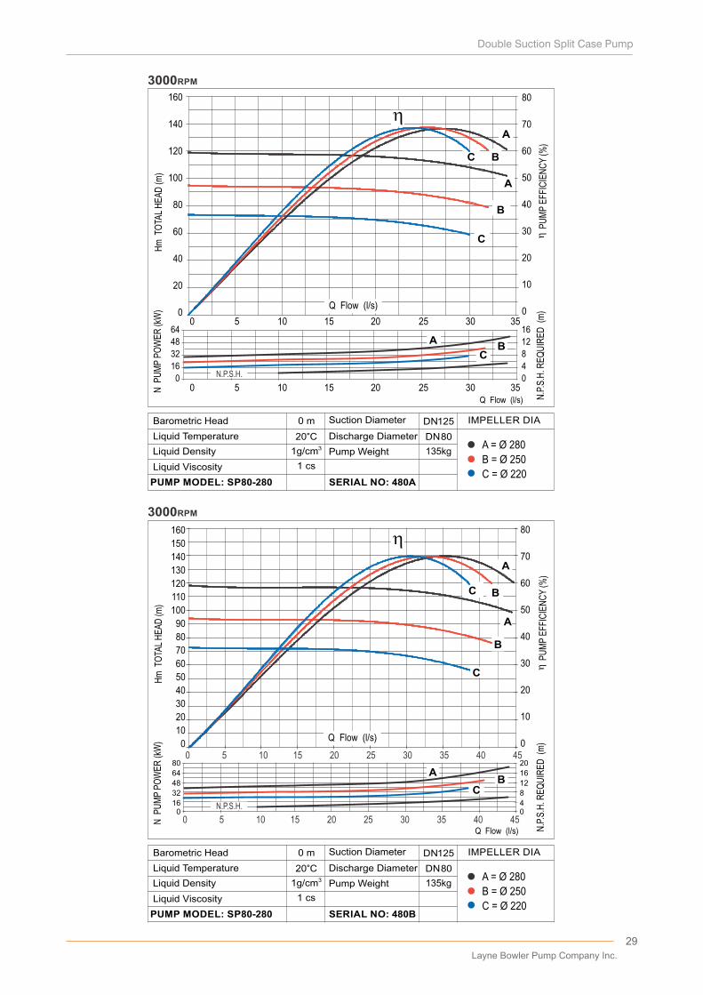
29
B = Ø 250
A = Ø 280
C = Ø 220
0 m
20°C31g/cm
D�scharge D�ameter
Pump We�ght
SERIAL NO: 480B
L�qu�d V�scos�ty
PUMP MODEL: SP80-280
Barometr�c Head
L�qu�d Temperature
L�qu�d Dens�ty
Suct�on D�ameter IMPELLER DIA
1 cs
DN 125
DN 80
135kg
N.P
.S.H
. RE
QU
IRE
D (
m)
P
UM
P E
FFIC
IEN
CY
(%)
B = Ø 250
A = Ø 280
C = Ø 220
0 m
20°C31g/cm
D�scharge D�ameter
Pump We�ght
SERIAL NO: 480A
L�qu�d V�scos�ty
PUMP MODEL: SP80-280
Barometr�c Head
L�qu�d Temperature
L�qu�d Dens�ty
Suct�on D�ameter IMPELLER DIA
1 cs
DN 125
DN 80
135kg
N.P
.S.H
. RE
QU
IRE
D (
m)
P
UM
P E
FFIC
IEN
CY
(%)
N P
UM
P P
OW
ER
(kW
)
3000RPM
A
B
C
AB
C
A
B
C
10
20
30
40
50
60
70
80
90
100
110
120
130
140
150
160
0 5 10 15 20 25 30 35 40 45
10
20
30
40
50
60
70
80
0 5 10 15 20 25 30 35 40 45
0
16
32
48
64
80
0
Q Flow (l/s)
0
4
8
12
16
20
0
A
B
C
A
B
C
A
B
C
A
B
C
0
20
40
60
80
100
120
140
160
0
10
20
30
40
50
60
70
80
0 5 10 15 20 25 30 35
0
16
32
48
64A
BC
0
4
8
12
16
0 5 10 15 20 25 30 35Q Flow (l/s)
3000RPM
N.P.S.H.
N.P.S.H.
Hm
TO
TAL
HE
AD
(m)
Hm
TO
TAL
HE
AD
(m)
N P
UM
P P
OW
ER
(kW
)
Q Flow (l/s)
Q Flow (l/s)
Layne Bowler Pump Company Inc.
30
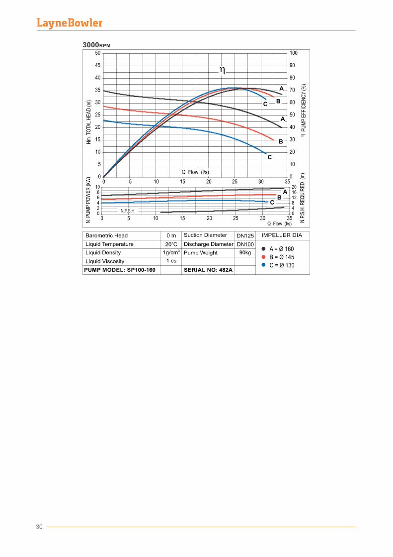
B = Ø 145
A = Ø 160
C = Ø 130
0 m
20°C31g/cm
D�scharge D�ameter
Pump We�ght
SERIAL NO: 482A
L�qu�d V�scos�ty
PUMP MODEL: SP100-160
Barometr�c Head
L�qu�d Temperature
L�qu�d Dens�ty
Suct�on D�ameter IMPELLER DIA
1 cs
DN 125
DN 100
90kg
N.P
.S.H
. RE
QU
IRE
D (
m)
P
UM
P E
FFIC
IEN
CY
(%)
Hm
TO
TAL
HE
AD
(m)
N P
UM
P P
OW
ER
(kW
) 0
5
10
15
20
25
30
35
40
45
50
0 5 10 15 20 25 30 350
10
20
30
40
50
60
70
80
90
100
02468
10
0 5 10 15 20 25 30 35048121620
..
)...
...
A
B
C
AB
C
A
B
C
3000RPM
Q Flow (l/s)
N.P.S.H.
Q Flow (l/s)
31
0
10
20
30
40
50
60
70
80
90
100
110
120
130
140
150
160
0
10
20
30
40
50
60
70
80
0
20
40
60
80
0
10
20
30
40
A
B
C
AB
C
A
B
C
0 10 20 30 40 50 60 70 80
0 10 20 30 40 50 60 70 80
Q Flow (l/s)
3000RPM
0
10
20
30
40
50
60
70
80
90
100
110
120
130
140
150
160
0
10
20
30
40
50
60
70
80
0
20
40
60
80
0
10
20
30
40
A
B
C
AB
C
AB
C
3000RPM
0 20 30 40 50 60 70 10
0 10 20 30 40 50 60 70
Q Flow (l/s)
...
Q Flow (l/s)
Q Flow (l/s)
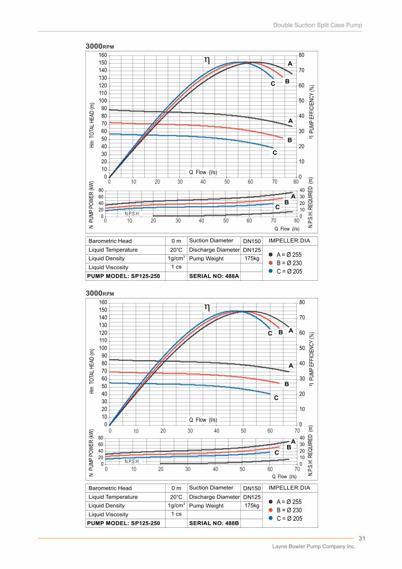
B = Ø 230
A = Ø 255
C = Ø 205
0 m
20°C31g/cm
D�scharge D�ameter
Pump We�ght
SERIAL NO: 488B
L�qu�d V�scos�ty
PUMP MODEL: SP125-250
Barometr�c Head
L�qu�d Temperature
L�qu�d Dens�ty
Suct�on D�ameter IMPELLER DIA
1 cs
DN 150
DN 125
175kg
P
UM
P E
FFIC
IEN
CY
(%)
N.P
.S.H
. RE
QU
IRE
D (
m)
B = Ø 230
A = Ø 255
C = Ø 205
0 m
20°C31g/cm
D�scharge D�ameter
Pump We�ght
SERIAL NO: 488A
L�qu�d V�scos�ty
PUMP MODEL: SP125-250
Barometr�c Head
L�qu�d Temperature
L�qu�d Dens�ty
Suct�on D�ameter IMPELLER DIA
1 cs
DN 150
DN125
175kg
N P
UM
P P
OW
ER
(kW
)H
m T
OTA
L H
EA
D (m
)
P
UM
P E
FFIC
IEN
CY
(%)
N.P
.S.H
. RE
QU
IRE
D (
m)
N.P.S.H.
N.P.S.H.
Hm
TO
TAL
HE
AD
(m)
N P
UM
P P
OW
ER
(kW
)
Layne Bowler Pump Company Inc.
32
A
B
CA
B
C
0
10
20
30
40
50
60
70
80
90
100
110
120
130
140
150
160
0
10
20
30
40
50
60
70
80
020406080
100120140
05101520253035
0 10 20 30 40 50 60 70 8 0 Q Flow (l/s)
3000RPM
0 10 20 30 40 50 60 70 8 0
0
10
20
30
40
50
60
70
80
90
100
110
120
130
140
150
160
0
10
20
30
40
50
60
70
80
04080
120160200
0816243240
A
B
C
AB
C
A
B
C
0 10 20 30 40 5 0 60 70 80 90 100
0 10 20 30 40 5 0 60 70 80 90 100
Q Flow (l/s)
...
3000RPM
N.P.S.H.
N.P.S.H.
BA
C
Q Flow (l/s)
Q Flow (l/s)
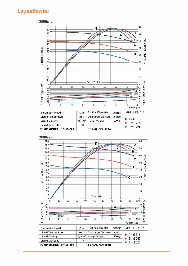
B = Ø 285
A = Ø 315
C = Ø 255
0 m
20°C31g/cm
D�scharge D�ameter
Pump We�ght
SERIAL NO: 489B
L�qu�d V�scos�ty
PUMP MODEL: SP125-300
Barometr�c Head
L�qu�d Temperature
L�qu�d Dens�ty
Suct�on D�ameter IMPELLER DIA
1 cs
DN1 50
DN 125
230kg
P
UM
P E
FFIC
IEN
CY
(%)
N P
UM
P P
OW
ER
(kW
)
B = Ø 285
A = Ø 315
C = Ø 255
0 m
20°C31g/cm
D�scharge D�ameter
Pump We�ght
SERIAL NO: 489A
L�qu�d V�scos�ty
PUMP MODEL: SP125-300
Barometr�c Head
L�qu�d Temperature
L�qu�d Dens�ty
Suct�on D�ameter IMPELLER DIA
1 cs
DN 150
DN1 25
230kg
N P
UM
P P
OW
ER
(kW
)
P
UM
P E
FFIC
IEN
CY
(%)
Hm
TO
TAL
HE
AD
(m)
N.P
.S.H
. RE
QU
IRE
D (
m)
Hm
TO
TAL
HE
AD
(m)
N.P
.S.H
. RE
QU
IRE
D (
m)
PerformanceCurves
1500rpm
33
Layne Bowler Pump Company Inc.
34
A
B
C
A
B
C
A
B
C
AB
C
A
B
C
1500RPM
0
5
10
15
20
25
30
35
40
45
50
0
10
20
30
40
50
60
70
80
90
100
0 5
0 502468
10
048121620
Q Flow (l/s)
A
B
C
A
B
C
A
B
C
A
B
C
A
B
C
0
5
10
15
20
25
30
35
40
45
50
0
10
20
30
40
50
60
70
80
90
100
02468
10
048121620
0 5 10 15 20 25 30 35
0 5 10 15 20 25 30 35Q Flow (l/s)
1500RPM
Q Flow (l/s)
Q Flow (l/s)
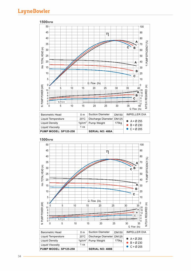
B = Ø 230
A = Ø 255
C = Ø 205
0 m
20°C31g/cm
D�scharge D�ameter
Pump We�ght
SERIAL NO: 488B
L�qu�d V�scos�ty
PUMP MODEL: SP125-250
Barometr�c Head
L�qu�d Temperature
L�qu�d Dens�ty
Suct�on D�ameter IMPELLER DIA
1 cs
DN 150
DN 125
175kg
N P
UM
P P
OW
ER
(kW
)
N.P
.S.H
. RE
QU
IRE
D (
m)
B = Ø 230
A = Ø 255
C = Ø 205
0 m
20°C31g/cm
D�scharge D�ameter
Pump We�ght
SERIAL NO: 488A
L�qu�d V�scos�ty
PUMP MODEL: SP125-250
Barometr�c Head
L�qu�d Temperature
L�qu�d Dens�ty
Suct�on D�ameter IMPELLER DIA
1 cs
DN 150
DN 125
175kg
10 15 20 25 30 35 40
10 15 20 25 30 35 40
N.P.S.H.
N.P.S.H.
Hm
TO
TAL
HE
AD
(m)
N P
UM
P P
OW
ER
(kW
)
N.P
.S.H
. RE
QU
IRE
D (
m)
P
UM
P E
FFIC
IEN
CY
(%)
Hm
TO
TAL
HE
AD
(m)
P
UM
P E
FFIC
IEN
CY
(%)

35
A
B
CA
B
C
A
B
CAB
C
0
10
20
30
40
50
60
70
80
90
100
0
10
20
30
40
50
60
70
80
90
100
0
5
10
15
20
0
5
10
15
20
0 5 10 15 20 25 30 35 40Q Flow (l/s)
1500RPM
1500RPM
A
B
C AB
C
A
B
C AB
C
Q Flow (l/s)
05
10152025
0510152025
0
10
20
30
40
50
60
70
80
90
100
0
10
20
30
40
50
60
70
80
90
100
0 5 10 15 20 25 30 35 40 45 50
0 5 10 15 20 25 30 35 40 45 50
0 5 10 15 20 25 30 35 40
Q Flow (l/s)
Q Flow (l/s)
B = Ø 285
A = Ø 315
C = Ø 255
0 m
20°C31g/cm
D�scharge D�ameter
Pump We�ght
SERIAL NO: 489B
L�qu�d V�scos�ty
PUMP MODEL: SP125-300
Barometr�c Head
L�qu�d Temperature
L�qu�d Dens�ty
Suct�on D�ameter IMPELLER DIA
1 cs
DN 150
DN 125
230kg
B = Ø 285
A = Ø 315
C = Ø 255
0 m
20°C31g/cm
D�scharge D�ameter
Pump We�ght
SERIAL NO: 489A
L�qu�d V�scos�ty
PUMP MODEL: SP125-300
Barometr�c Head
L�qu�d Temperature
L�qu�d Dens�ty
Suct�on D�ameter IMPELLER DIA
1 cs
DN 150
DN125
230kg
N P
UM
P P
OW
ER
(kW
)
N.P.S.H.
N.P.S.H.
Hm
TO
TAL
HE
AD
(m)
N.P
.S.H
. RE
QU
IRE
D (
m)
P
UM
P E
FFIC
IEN
CY
(%)
Hm
TO
TAL
HE
AD
(m)
N P
UM
P P
OW
ER
(kW
)
N.P
.S.H
. RE
QU
IRE
D (
m)
P
UM
P E
FFIC
IEN
CY
(%)
Layne Bowler Pump Company Inc.
36
1500RPM
0
10
20
30
40
50
60
70
80
90
100
0
10
20
30
40
50
60
70
80
90
100
0
10
20
30
40
0
10
20
30
40
A
B
C
AB
C
AB
C
0 10 20 30 40 50 60 70 80
0 10 20 30 40 50 60 70 80Q Flow (l/s)
10
20
30
40
50
60
70
80
90
100
10
20
30
40
50
60
70
80
90
100
A
B
CA
B
C
00
0
10
20
30
0102030405060
A
B
CA
B
C
0 10 20 30 40 50 60 70 80 90 100
..
.. ..
....
Q Flow (l/s)
1500RPM
0 10 20 30 40 50 60 70 80 90 100
AB
C
Q Flow (l/s)
Q Flow (l/s)
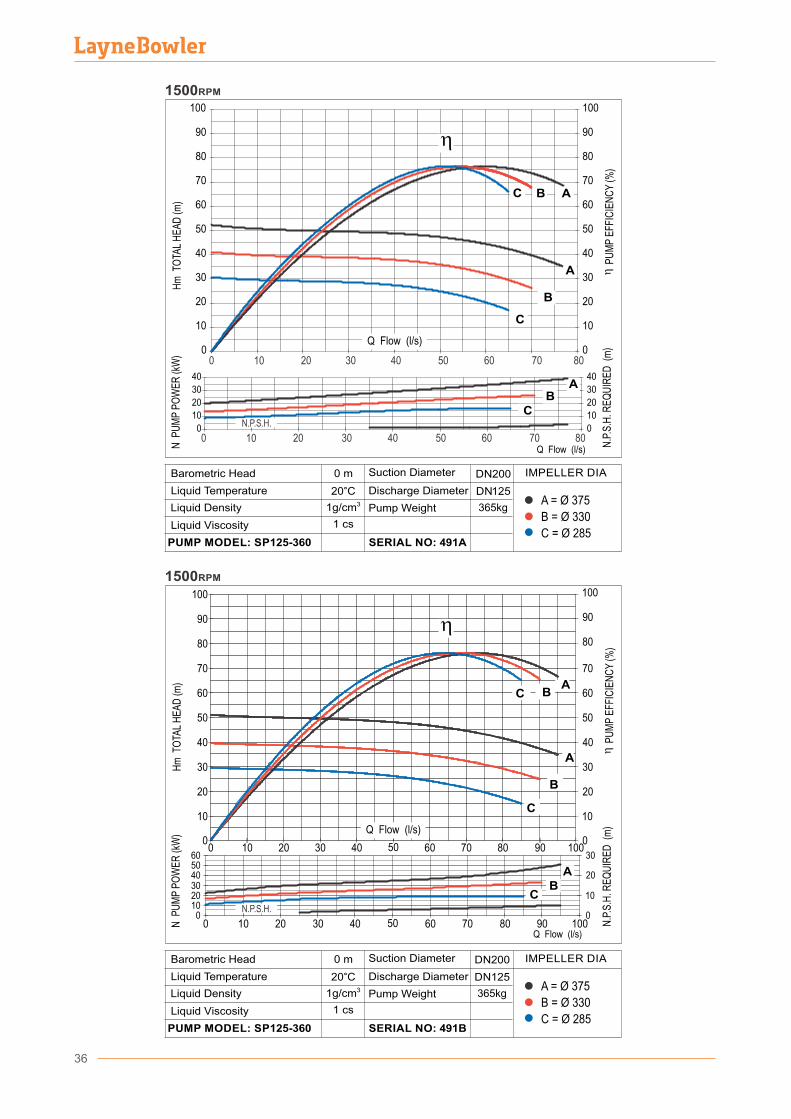
B = Ø 330
A = Ø 375
C = Ø 285
0 m
20°C31g/cm
D�scharge D�ameter
Pump We�ght
SERIAL NO: 491B
L�qu�d V�scos�ty
PUMP MODEL: SP125-360
Barometr�c Head
L�qu�d Temperature
L�qu�d Dens�ty
Suct�on D�ameter IMPELLER DIA
1 cs
DN125
365kg
B = Ø 330
A = Ø 375
C = Ø 285
0 m
20°C31g/cm
D�scharge D�ameter
Pump We�ght
SERIAL NO: 491A
L�qu�d V�scos�ty
PUMP MODEL: SP125-360
Barometr�c Head
L�qu�d Temperature
L�qu�d Dens�ty
Suct�on D�ameter IMPELLER DIA
1 cs
DN 200
DN 125
365kg
N.P.S.H.
N.P.S.H.
Hm
TO
TAL
HE
AD
(m)
N P
UM
P P
OW
ER
(kW
)
N.P
.S.H
. RE
QU
IRE
D (
m)
P
UM
P E
FFIC
IEN
CY
(%)
Hm
TO
TAL
HE
AD
(m)
N P
UM
P P
OW
ER
(kW
)
N.P
.S.H
. RE
QU
IRE
D (
m)
P
UM
P E
FFIC
IEN
CY
(%)
DN200
37
Q Debi (l/s)
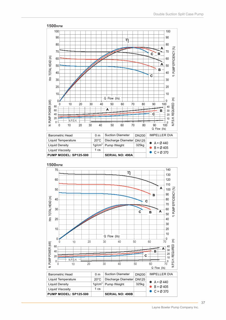
B = Ø 405
A = Ø 440
C = Ø 370
0 m
20°C31g/cm
D�scharge D�ameter
Pump We�ght
SERIAL NO: 490B
L�qu�d V�scos�ty
PUMP MODEL: SP125-500
Barometr�c Head
L�qu�d Temperature
L�qu�d Dens�ty
Suct�on D�ameter IMPELLER DIA
1 cs
DN 200
DN 125
325kg
N P
UM
P P
OW
ER
(kW
)
B = Ø 405
A = Ø 440
C = Ø 370
0 m
20°C31g/cm
D�scharge D�ameter
Pump We�ght
SERIAL NO: 490A
L�qu�d V�scos�ty
PUMP MODEL: SP125-500
Barometr�c Head
L�qu�d Temperature
L�qu�d Dens�ty
Suct�on D�ameter IMPELLER DIA
1 cs
DN 200
325kg
10
20
30
40
50
60
70
80
90
100
10
20
30
40
50
60
70
80
90
100
A
B
C
A
B
C
00
0
10
20
30
40
0
20
40
60
80
A
B
C
A BC
A
B
C
0 10 20 30 40 50 60 70 80 90 100
......
Q Flow (l/s)0 10 20 30 40 50 60 70 80 90 100
1500RPM
1500RPM
0
10
20
30
40
50
60
70
0
10
20
30
40
50
60
70
80
90
100
110
120
130
140
0
20
40
60
0
10
20
30
40
AB
C
AB
C
A
B
C
Q Flow (l/s)
0 20 30 40 50 60 70 10
0 20 30 40 50 60 70 10
N.P.S.H.
N.P.S.H.
Hm
TO
TAL
HE
AD
(m)
N P
UM
P P
OW
ER
(kW
)
N.P
.S.H
. RE
QU
IRE
D (
m)
P
UM
P E
FFIC
IEN
CY
(%)
DN125
Hm
TO
TAL
HE
AD
(m)
N.P
.S.H
. RE
QU
IRE
D (
m)
P
UM
P E
FFIC
IEN
CY
(%)
Q Flow (l/s)
Q Flow (l/s)
Layne Bowler Pump Company Inc.
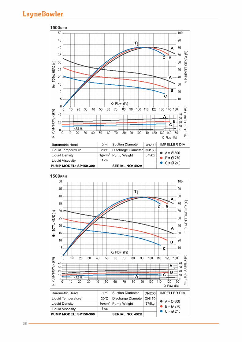
38
0
5
10
15
20
25
30
35
40
45
50
0 10 20 30 40 50 60 70 80 90 100 110 120 130 140 1500
10
20
30
40
50
60
70
80
90
100
0
20
40
0
10
20
30
40
A
B
C
A
BC
A
B
C
0 10 20 30 40 50 60 70 80 90 100 110 120 130 140 150
1500RPM
Q Flow (l/s)
...
1500RPM
0
5
10
15
20
25
30
35
40
45
50
0
10
20
30
40
50
60
70
80
90
100
0
10
20
30
40
0
10
20
30
40
A
B
C
A
BC
A
A
B
C
100 20 30 40 50 60 70 80 90 100 110 120 130
100 20 30 40 50 60 70 80 90 100 110 120 130Q Flow (l/s)
Q Flow (l/s)
Q Flow (l/s)
B = Ø 270
A = Ø 300
C = Ø 240
0 m
20°C31g/cm
D�scharge D�ameter
Pump We�ght
SERIAL NO: 492B
L�qu�d V�scos�ty
PUMP MODEL: SP150-300
Barometr�c Head
L�qu�d Temperature
L�qu�d Dens�ty
Suct�on D�ameter IMPELLER DIA
1 cs
DN 200
DN 150
375kg
B = Ø 270
A = Ø 300
C = Ø 240
0 m
20°C31g/cm
D�scharge D�ameter
Pump We�ght
SERIAL NO: 492A
L�qu�d V�scos�ty
PUMP MODEL: SP150-300
Barometr�c Head
L�qu�d Temperature
L�qu�d Dens�ty
Suct�on D�ameter IMPELLER DIA
1 cs
DN 200
DN 150
375kg
N.P.S.H.
N.P.S.H.
Hm
TO
TAL
HE
AD
(m)
N P
UM
P P
OW
ER
(kW
)
N.P
.S.H
. RE
QU
IRE
D (
m)
P
UM
P E
FFIC
IEN
CY
(%)
Hm
TO
TAL
HE
AD
(m)
N P
UM
P P
OW
ER
(kW
)
N.P
.S.H
. RE
QU
IRE
D (
m)
P
UM
P E
FFIC
IEN
CY
(%)
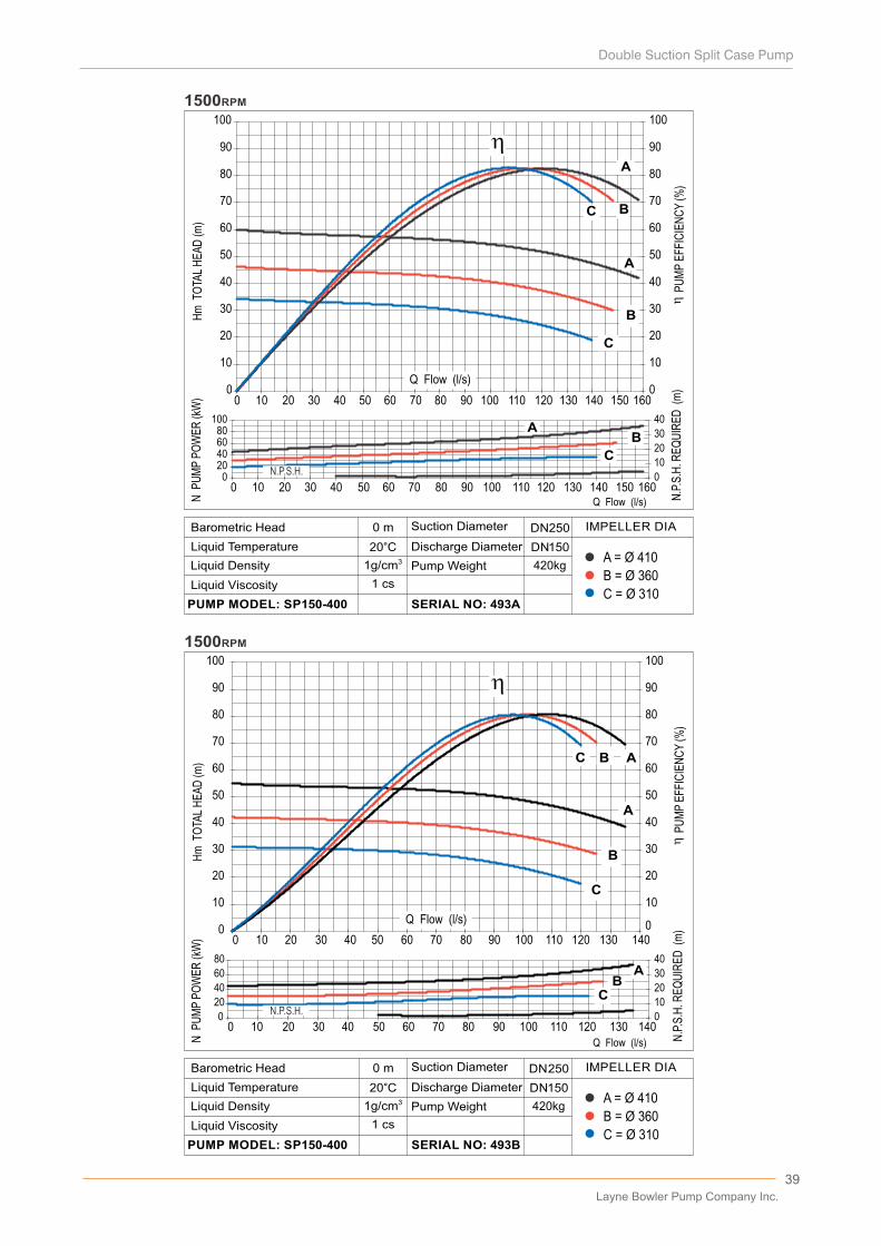
39
0
10
20
30
40
50
60
70
80
90
100
0 10 20 30 40 50 60 70 80 90 100 110 120 130 140 150 1600
10
20
30
40
50
60
70
80
90
100
020406080
100
0
10
20
30
40
A
B
C
AB
C
A
B
C
Q Flow (l/s)
0 10 20 30 40 50 60 70 80 90 100 110 120 130 140 150 160
1500RPM
1500RPM
0
10
20
30
40
50
60
70
80
90
100
0
10
20
30
40
50
60
70
80
90
100
0
20
40
60
80
0
10
20
30
40
A
B
C
AB
C
AB
C
0 10 20 30 40 50 60 70 80 90 100 110 120 130 140
0 10 20 30 40 50 60 70 80 90 100 110 120 130 140Q Flow (l/s)N
PU
MP
PO
WE
R (k
W)
P
UM
P E
FFIC
IEN
CY
(%)
Q Flow (l/s)
Q Flow (l/s)
B = Ø 360
A = Ø 410
C = Ø 310
0 m
20°C31g/cm
D�scharge D�ameter
Pump We�ght
SERIAL NO: 493A
L�qu�d V�scos�ty
PUMP MODEL: SP150-400
Barometr�c Head
L�qu�d Temperature
L�qu�d Dens�ty
Suct�on D�ameter IMPELLER DIA
1 cs
DN 250
DN 150
420kg
N.P.S.H.
N.P.S.H.
Hm
TO
TAL
HE
AD
(m)
N P
UM
P P
OW
ER
(kW
)
N.P
.S.H
. RE
QU
IRE
D (
m)
P
UM
P E
FFIC
IEN
CY
(%)
B = Ø 360
A = Ø 410
C = Ø 310
0 m
20°C31g/cm
D�scharge D�ameter
Pump We�ght
SERIAL NO: 493B
L�qu�d V�scos�ty
PUMP MODEL: SP150-400
Barometr�c Head
L�qu�d Temperature
L�qu�d Dens�ty
Suct�on D�ameter IMPELLER DIA
1 cs
DN 250
DN150
420kg
Hm
TO
TAL
HE
AD
(m)
N.P
.S.H
. RE
QU
IRE
D (
m)
Layne Bowler Pump Company Inc.
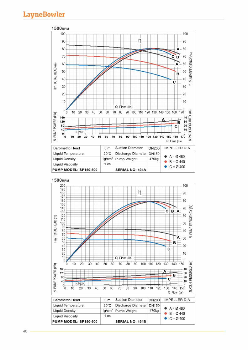
40
1500RPM
0
10
20
30
40
50
60
70
80
90
100
0 10 20 30 40 50 60 70 80 90 100 110 120 130 140 150 160 1700
10
20
30
40
50
60
70
80
90
100
0
40
80
120
160
0 10 20 30 40 50 60 70 80 90 100 110 120 130 140 150 160 1700
10
20
30
40
A
B
C
AB
C
A
B
C
Q Flow (l/s)
0102030405060708090
100110120130140150160170180190200
0 10 20 30 40 50 60 70 80 90 100 110 120 130 140 1500
10
20
30
40
50
60
70
80
90
100
0
40
80
120
160
0
10
20
30
40
A
B
C
AB
C
AB
C
0 10 20 30 40 50 60 70 80 90 100 110 120 130 140 150Q Flow (l/s)
1500RPM
Q Flow (l/s)
Q Flow (l/s)
B = Ø 440
A = Ø 480
C = Ø 400
0 m
20°C31g/cm
D�scharge D�ameter
Pump We�ght
SERIAL NO: 494B
L�qu�d V�scos�ty
PUMP MODEL: SP150-500
Barometr�c Head
L�qu�d Temperature
L�qu�d Dens�ty
Suct�on D�ameter IMPELLER DIA
1 cs
DN 200
DN1 50
470kg
B = Ø 440
A = Ø 480
C = Ø 400
0 m
20°C31g/cm
D�scharge D�ameter
Pump We�ght
SERIAL NO: 494A
L�qu�d V�scos�ty
PUMP MODEL: SP150-500
Barometr�c Head
L�qu�d Temperature
L�qu�d Dens�ty
Suct�on D�ameter IMPELLER DIA
1 cs
DN 200
DN 150
470kg
N.P.S.H.
N.P.S.H.
Hm
TO
TAL
HE
AD
(m)
N P
UM
P P
OW
ER
(kW
)
N.P
.S.H
. RE
QU
IRE
D (
m)
P
UM
P E
FFIC
IEN
CY
(%)
Hm
TO
TAL
HE
AD
(m)
P
UM
P E
FFIC
IEN
CY
(%)
N P
UM
P P
OW
ER
(kW
)
N.P
.S.H
. RE
QU
IRE
D (
m)
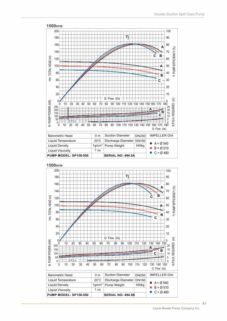
41
10
20
30
40
50
60
70
80
90
100
20
40
60
80
100
120
140
160
180
200
A
B
C
A
B
C
000 10 20 30 40 50 60 70 80 90 100 110 120 130 140 150 160 170 180
BC
B
Q Flow (l/s)
0510152025
050100150200250
BC
0 10 20 30 40 50 60 70 80 90 100 110 120 130 140 150 160 170 180
1500RPM
A
A
C
0 10 20 30 40 50 60 70 80 90 100 110 120 130 140 150
A
B
C
A
B
C
A
B
C
A
B
C
20
40
60
80
100
120
140
160
180
200
0
10
20
30
40
50
60
70
80
90
100
0
0
5
10
15
20
50
100
150
200A
BC
00 10 20 30 40 50 60 70 80 90 100 110 120 130 140 150
Q Flow (l/s)
1500RPM
N.P.S.H.
A
Q Flow (l/s)
Q Flow (l/s)
B = Ø 510
A = Ø 540
C = Ø 480
0 m
20°C31g/cm
D�scharge D�ameter
Pump We�ght
SERIAL NO: 494.5B
L�qu�d V�scos�ty
PUMP MODEL: SP150-550
Barometr�c Head
L�qu�d Temperature
L�qu�d Dens�ty
Suct�on D�ameter IMPELLER DIA
1 cs
DN 250
DN1 50
540kg
N P
UM
P P
OW
ER
(kW
)
B = Ø 510
A = Ø 540
C = Ø 480
0 m
20°C31g/cm
D�scharge D�ameter
Pump We�ght
SERIAL NO: 494.5A
L�qu�d V�scos�ty
PUMP MODEL: SP150-550
Barometr�c Head
L�qu�d Temperature
L�qu�d Dens�ty
Suct�on D�ameter IMPELLER DIA
1 cs
DN 250
DN 150
540kg
N.P.S.H.
Hm
TO
TAL
HE
AD
(m)
N P
UM
P P
OW
ER
(kW
)
N.P
.S.H
. RE
QU
IRE
D (
m)
P
UM
P E
FFIC
IEN
CY
(%)
Hm
TO
TAL
HE
AD
(m)
N.P
.S.H
. RE
QU
IRE
D (
m)
P
UM
P E
FFIC
IEN
CY
(%)
Layne Bowler Pump Company Inc.
42
1500RPM
0102030405060708090
100110120130140150160170180190200
0 10 20 30 40 50 60 70 80 90 100 110 120 130 140 150 160 170 1800
10
20
30
40
50
60
70
80
90
100
0
80
160
240
320
0
10
20
30
40
A
B
C
AB
C
AB
C
Q Flow (l/s)
...
0 10 20 30 40 50 60 70 80 90 100 110 120 130 140 150 160 170 180
AB
C AB
C
0102030405060708090
100110120130140150160170180190200
0 10 20 30 40 50 60 70 80 90 100 110 120 130 140 150 1600
10
20
30
40
50
60
70
80
90
100
0
80
160
240
320
0
10
20
30
40
...
A
BC
0 10 20 30 40 50 60 70 80 90 100 110 120 130 140 150 160Q Flow (l/s)
1500RPM
N.P.S.H.
N.P.S.H.
Q Flow (l/s)
Q Flow (l/s)
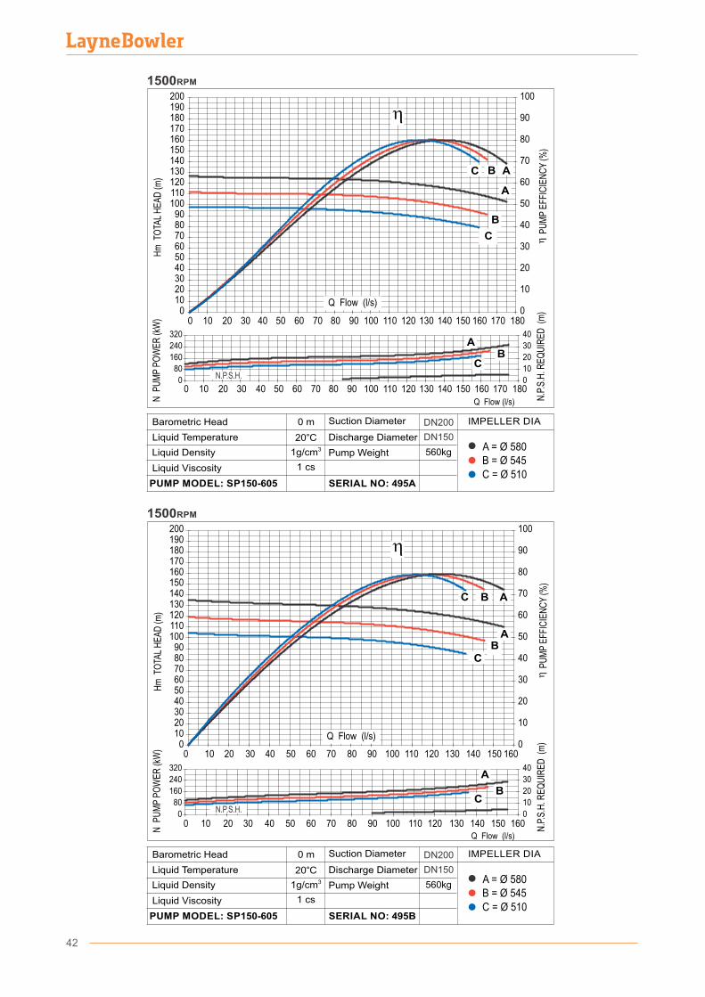
B = Ø 545A = Ø 580
C = Ø 510
560kg
DN200
DN150
0 m
20°C31g/cm
D�scharge D�ameter
Pump We�ght
SERIAL NO: 495B
L�qu�d V�scos�ty
PUMP MODEL: SP150-605
Barometr�c Head
L�qu�d Temperature
L�qu�d Dens�ty
Suct�on D�ameter IMPELLER DIA
1 cs
B = Ø 545A = Ø 580
C = Ø 510
560kg
DN200
DN150
0 m
20°C31g/cm
D�scharge D�ameter
Pump We�ght
SERIAL NO: 495A
L�qu�d V�scos�ty
PUMP MODEL: SP150-605
Barometr�c Head
L�qu�d Temperature
L�qu�d Dens�ty
Suct�on D�ameter IMPELLER DIA
1 cs
Hm
TO
TAL
HE
AD
(m)
N P
UM
P P
OW
ER
(kW
)
N.P
.S.H
. RE
QU
IRE
D (
m)
P
UM
P E
FFIC
IEN
CY
(%)
Hm
TO
TAL
HE
AD
(m)
N P
UM
P P
OW
ER
(kW
)
N.P
.S.H
. RE
QU
IRE
D (
m)
P
UM
P E
FFIC
IEN
CY
(%)
43
0
10
20
30
40
50
60
70
80
90
100
0 20 40 60 80 100 120 140 160 180 200 220 2400
10
20
30
40
50
60
70
80
90
100
020406080
100
01020304050
A
B
C
AB
C
AB
C
0 20 40 60 80 100 120 140 160 180 200 220 240
Q Flow (l/s)
...
1500RPM
0
10
20
30
40
50
60
70
80
90
100
0 20 40 60 80 100 120 140 160 180 2000
10
20
30
40
50
60
70
80
90
100
020406080
100
01020304050
A
B
C
AB
C
AB
C
0 20 40 60 80 100 120 140 160 180 200
Q Flow (l/s)
1500RPM
N.P.S.H.
N.P.S.H.
Q Flow (l/s)
Q Flow (l/s)
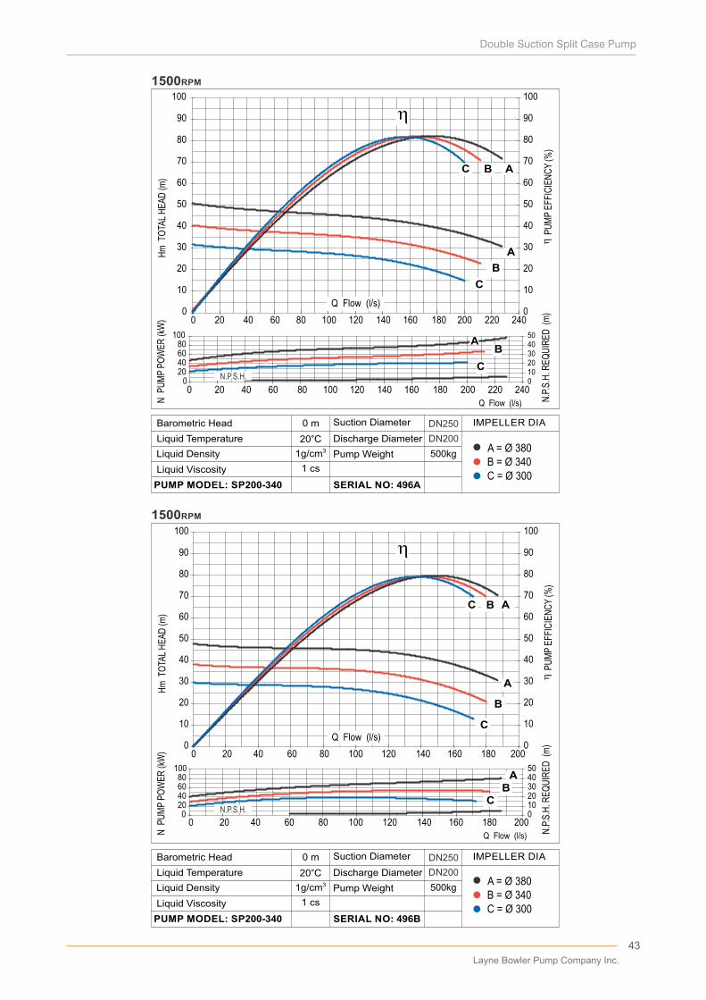
B = Ø 340A = Ø 380
C = Ø 300
500kg
DN250
DN200
0 m
20°C31g/cm
D�scharge D�ameter
Pump We�ght
SERIAL NO: 496B
L�qu�d V�scos�ty
PUMP MODEL: SP200-340
Barometr�c Head
L�qu�d Temperature
L�qu�d Dens�ty
Suct�on D�ameter IMPELLER DIA
1 cs
N P
UM
P P
OW
ER
(kW
)
B = Ø 340A = Ø 380
C = Ø 300
500kg
DN250
DN200
0 m
20°C31g/cm
D�scharge D�ameter
Pump We�ght
SERIAL NO: 496A
L�qu�d V�scos�ty
PUMP MODEL: SP200-340
Barometr�c Head
L�qu�d Temperature
L�qu�d Dens�ty
Suct�on D�ameter IMPELLER DIA
1 cs
Hm
TO
TAL
HE
AD
(m)
N P
UM
P P
OW
ER
(kW
)
N.P
.S.H
. RE
QU
IRE
D (
m)
P
UM
P E
FFIC
IEN
CY
(%)
Hm
TO
TAL
HE
AD
(m)
N.P
.S.H
. RE
QU
IRE
D (
m)
P
UM
P E
FFIC
IEN
CY
(%)
Layne Bowler Pump Company Inc.
44
0102030405060708090
100110120130140150160170180190200
0 20 40 60 80 100 120 140 160 180 200 220 2400
10
20
30
40
50
60
70
80
90
100
050
100150200250
01020304050
A
B
C
AB
C
A
B
C
0 20 40 60 80 100 120 140 160 180 200 220 240
Q Flow (l/s)
...
1500RPM
0102030405060708090
100110120130140150160170180190200
0 20 40 60 80 100 120 140 160 180 2000
10
20
30
40
50
60
70
80
90
100
0
50
100
150
200
0
10
20
30
40
..
A
B
C
AB
C
AB
C
0 20 40 60 80 100 120 140 160 180 200
1500RPM
Q Flow (l/s)
Q Flow (l/s)
Q Flow (l/s)
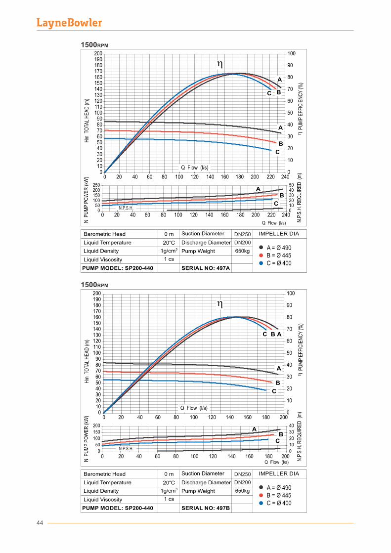
650kg
DN250
DN200
B = Ø 445A = Ø 490
C = Ø 400
0 m
20°C31g/cm
D�scharge D�ameter
Pump We�ght
SERIAL NO: 497B
L�qu�d V�scos�ty
PUMP MODEL: SP200-440
Barometr�c Head
L�qu�d Temperature
L�qu�d Dens�ty
Suct�on D�ameter IMPELLER DIA
1 cs
B = Ø 445A = Ø 490
C = Ø 400
650kg
DN250
DN200
0 m
20°C31g/cm
D�scharge D�ameter
Pump We�ght
SERIAL NO: 497A
L�qu�d V�scos�ty
PUMP MODEL: SP200-440
Barometr�c Head
L�qu�d Temperature
L�qu�d Dens�ty
Suct�on D�ameter IMPELLER DIA
1 cs
N.P.S.H.
N.P.S.H.
Hm
TO
TAL
HE
AD
(m)
N P
UM
P P
OW
ER
(kW
)
N.P
.S.H
. RE
QU
IRE
D (
m)
P
UM
P E
FFIC
IEN
CY
(%)
Hm
TO
TAL
HE
AD
(m)
N P
UM
P P
OW
ER
(kW
)
N.P
.S.H
. RE
QU
IRE
D (
m)
P
UM
P E
FFIC
IEN
CY
(%)
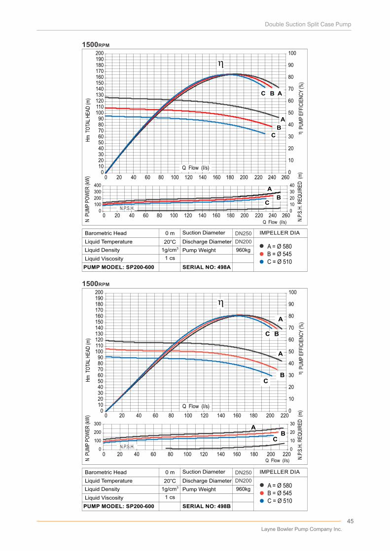
45
0102030405060708090
100110120130140150160170180190200
0 20 40 60 80 100 120 140 160 180 200 220 240 2600
10
20
30
40
50
60
70
80
90
100
0
100
200
300
400
0
10
20
30
40
A
BC
A
BC
A
B
C
0 20 40 60 80 100 120 140 160 180 200 220 240 260Q Flow (l/s)
...
1500RPM
0102030405060708090
100110120130140150160170180190200
0 20 40 60 80 100 120 140 160 180 200 2200
10
20
30
40
50
60
70
80
90
100
0
100
200
300
0
10
20
30
A
B
C
AB
C
A
B
C
0 20 40 60 80 100 120 140 160 180 200 220Q Flow (l/s)
1500RPM
N.P.S.H.
N.P.S.H.
Q Flow (l/s)
Q Flow (l/s)
B = Ø 545A = Ø 580
C = Ø 510
960kg
DN250
DN200
0 m
20°C31g/cm
D�scharge D�ameter
Pump We�ght
SERIAL NO: 498B
L�qu�d V�scos�ty
PUMP MODEL: SP200-600
Barometr�c Head
L�qu�d Temperature
L�qu�d Dens�ty
Suct�on D�ameter IMPELLER DIA
1 cs
B = Ø 545A = Ø 580
C = Ø 510
960kg
DN250
DN200
0 m
20°C31g/cm
D�scharge D�ameter
Pump We�ght
SERIAL NO: 498A
L�qu�d V�scos�ty
PUMP MODEL: SP200-600
Barometr�c Head
L�qu�d Temperature
L�qu�d Dens�ty
Suct�on D�ameter IMPELLER DIA
1 cs
Hm
TO
TAL
HE
AD
(m)
N P
UM
P P
OW
ER
(kW
)
N.P
.S.H
. RE
QU
IRE
D (
m)
P
UM
P E
FFIC
IEN
CY
(%)
Hm
TO
TAL
HE
AD
(m)
N P
UM
P P
OW
ER
(kW
)
N.P
.S.H
. RE
QU
IRE
D (
m)
P
UM
P E
FFIC
IEN
CY
(%)
Layne Bowler Pump Company Inc.
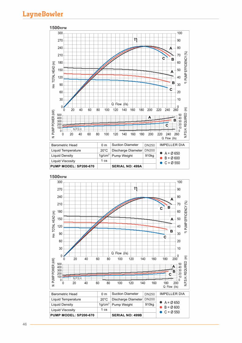
0
30
60
90
120
150
180
210
240
270
300
0 20 40 60 80 100 120 140 160 180 200 220 240 2600
10
20
30
40
50
60
70
80
90
100
0100200300400500
01020304050
A
B
C
AB
C
A
BC
0 20 40 60 80 100 120 140 160 180 200 220 240 260Q Flow (l/s)N
PU
MP
PO
WE
R (k
W)
Hm
TO
TAL
HE
AD
(m)
...
N.P
.S.H
. RE
QU
IRE
D (
m)
P
UM
P E
FFIC
IEN
CY
(%)
1500RPM
0
30
60
90
120
150
180
210
240
270
300
0 20 40 60 80 100 120 140 160 180 2000
10
20
30
40
50
60
70
80
90
100
0100200300400500
01020304050
A
B
C
A
BC
A
BC
0 20 40 60 80 100 120 140 160 180 200
Hm
TO
TAL
HE
AD
(m)
N P
UM
P P
OW
ER
(kW
)
N.P
.S.H
. RE
QU
IRE
D (
m)
P
UM
P E
FFIC
IEN
CY
(%)
Q Flow (l/s)
1500RPM
Q Flow (l/s)
Q Flow (l/s)
B = Ø 600A = Ø 650
C = Ø 550
910kg
DN250
DN200
0 m
20°C31g/cm
D�scharge D�ameter
Pump We�ght
SERIAL NO: 499B
L�qu�d V�scos�ty
PUMP MODEL: SP200-670
Barometr�c Head
L�qu�d Temperature
L�qu�d Dens�ty
Suct�on D�ameter IMPELLER DIA
1 cs
B = Ø 600A = Ø 650
C = Ø 550
910kg
DN250
DN200
0 m
20°C31g/cm
D�scharge D�ameter
Pump We�ght
SERIAL NO: 499A
L�qu�d V�scos�ty
PUMP MODEL: SP200-670
Barometr�c Head
L�qu�d Temperature
L�qu�d Dens�ty
Suct�on D�ameter IMPELLER DIA
1 cs
N.P.S.H.
N.P.S.H.
46
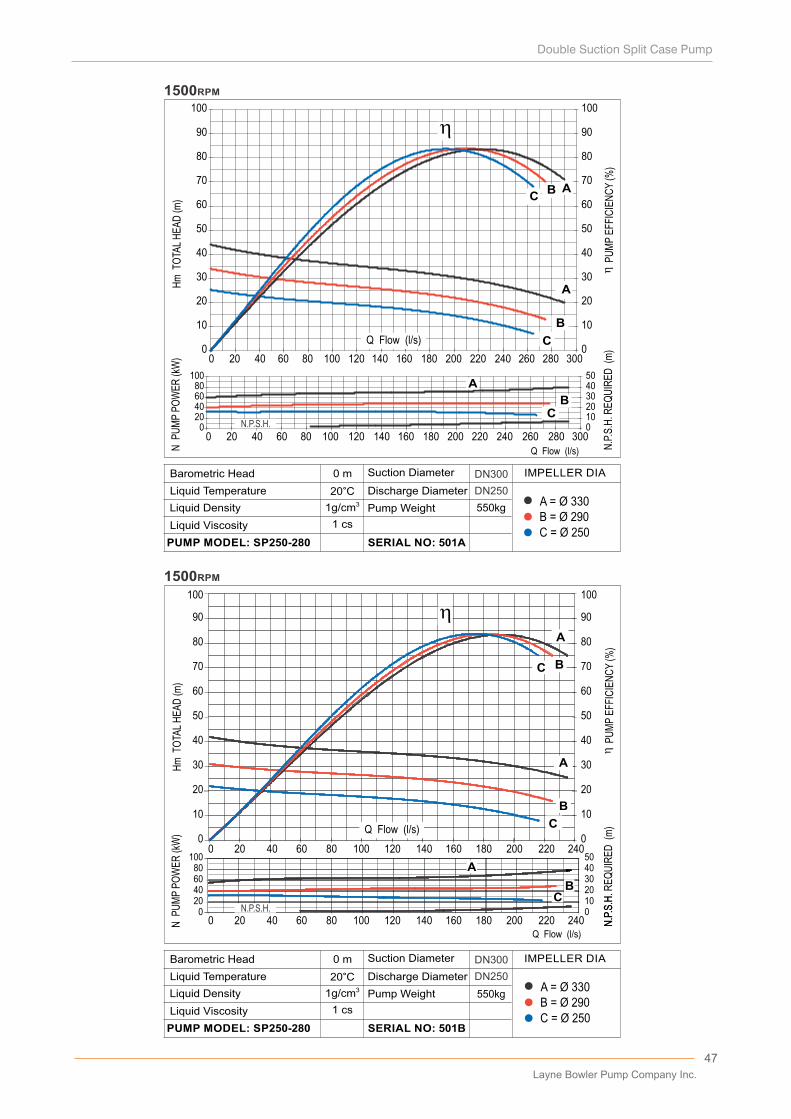
0
10
20
30
40
50
60
70
80
90
100
0 20 40 60 80 100 120 140 160 180 200 220 240 260 280 3000
10
20
30
40
50
60
70
80
90
100
020406080
100
01020304050
A
B
A
BC
C
0 20 40 60 80 100 120 140 160 180 200 220 240 260 280 300Q Flow (l/s)N
PU
MP
PO
WE
R (k
W)
Hm
TO
TAL
HE
AD
(m)
...
N.P
.S.H
. RE
QU
IRE
D (
m)
P
UM
P E
FFIC
IEN
CY
(%)
1500RPM
CB A
10
20
30
40
50
60
70
80
90
100
10
20
30
40
50
60
70
80
90
100..
.
A
B
C
A
B
C
00
...
A
B
C
0 20 40 60 80 100 120 140 160 180 200 220 240
01020304050
020406080100
0 20 40 60 80 100 120 140 160 180 200 220 240
..
..
Hm
TO
TAL
HE
AD
(m)
N P
UM
P P
OW
ER
(kW
)
...
...
N.P
.S.H
.
PU
MP
EFF
ICIE
NC
Y (%
)N
.P.S
.H. R
EQ
UIR
ED
(m
)
C
A
1500RPM
Q Flow (l/s)
B
CB
N.P.S.H.
N.P.S.H.
A
Q Flow (l/s)
Q Flow (l/s)
B = Ø 290A = Ø 330
C = Ø 250
550kg
DN300
DN250
0 m
20°C31g/cm
D�scharge D�ameter
Pump We�ght
SERIAL NO: 501B
L�qu�d V�scos�ty
PUMP MODEL: SP250-280
Barometr�c Head
L�qu�d Temperature
L�qu�d Dens�ty
Suct�on D�ameter IMPELLER DIA
1 cs
550kg
DN300
DN250
B = Ø 290A = Ø 330
C = Ø 250
0 m
20°C31g/cm
D�scharge D�ameter
Pump We�ght
SERIAL NO: 501A
L�qu�d V�scos�ty
PUMP MODEL: SP250-280
Barometr�c Head
L�qu�d Temperature
L�qu�d Dens�ty
Suct�on D�ameter IMPELLER DIA
1 cs
47
Layne Bowler Pump Company Inc.

0
10
20
30
40
50
60
70
80
90
100
110
120
0 50 100 150 200 250 300 3500
10
20
30
40
50
60
70
80
90
100
110
120
04080
120160200
048121620
A
B
C
AB
C
A
B
C
Hm
TO
TAL
HE
AD
(m)
N P
UM
P P
OW
ER
(kW
)
N.P
.S.H
. RE
QU
IRE
D (
m)
P
UM
P E
FFIC
IEN
CY
(%)
Q Flow (l/s)0 50 100 150 200 250 300 350
1500RPM
N.P.S.H.
3002752502252001751501251007550250
10
0
20
60
50
40
30
70
80
90
100
110
120
10
0
20
60
50
40
30
70
80
90
100
110
120
04080
120160200
048121620
Q Flow (l/s)
Hm
TO
TAL
HE
AD
(m)
N P
UM
P P
OW
ER
(kW
)
...
N.P
.S.H
. RE
QU
IRE
D (
m)
P
UM
P E
FFIC
IEN
CY
(%)
1500RPM
A
BC
A
B
C
AB
C
3002752502252001751501251007550250
N.P.S.H.
Q Flow (l/s)
Q Flow (l/s)
B = Ø 395
A = Ø 440
C = Ø 350
730kg
DN250
DN300
0 m
20°C31g/cm
D�scharge D�ameter
Pump We�ght
SERIAL NO: 502B
L�qu�d V�scos�ty
PUMP MODEL: SP250-400
Barometr�c Head
L�qu�d Temperature
L�qu�d Dens�ty
Suct�on D�ameter IMPELLER DIA
1 cs
730kg
DN300
DN250
B = Ø 395A = Ø 440
C = Ø 350
0 m
20°C31g/cm
D�scharge D�ameter
Pump We�ght
SERIAL NO: 502A
L�qu�d V�scos�ty
PUMP MODEL: SP250-400
Barometr�c Head
L�qu�d Temperature
L�qu�d Dens�ty
Suct�on D�ameter IMPELLER DIA
1 cs
48
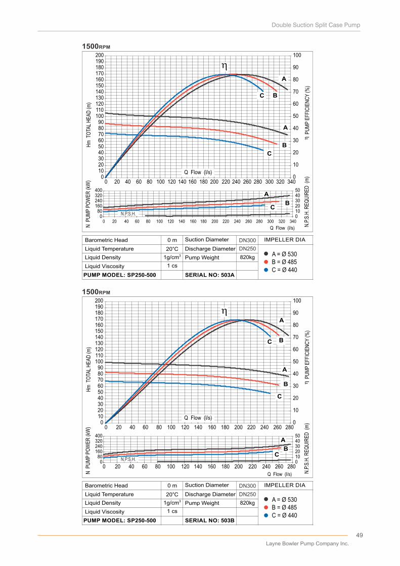
0102030405060708090
100110120130140150160170180190200
0 20 40 60 80 100 120 140 160 180 200 220 240 260 280 300 320 3400
10
20
30
40
50
60
70
80
90
100
080
160240320400
0 20 40 60 80 100 120 140 160 180 200 220 240 260 280 300 320 34001020304050
A
B
C
A
BC
A
B
C
Hm
TO
TAL
HE
AD
(m)
N P
UM
P P
OW
ER
(kW
)
N.P
.S.H
. RE
QU
IRE
D (
m)
P
UM
P E
FFIC
IEN
CY
(%)
Q Flow (l/s)
1500RPM
0102030405060708090
100110120130140150160170180190200
0 20 40 60 80 100 120 140 160 180 200 220 240 260 2800
10
20
30
40
50
60
70
80
90
100
080
160240320400
0 20 40 60 80 100 120 140 160 180 200 220 240 260 28001020304050
A
B
C
A
BC
A
B
C
Q Flow (l/s)N P
UM
P P
OW
ER
(kW
)H
m T
OTA
L H
EA
D (m
)
...
N.P
.S.H
. RE
QU
IRE
D (
m)
P
UM
P E
FFIC
IEN
CY
(%)
1500RPM
N.P.S.H.
Q Flow (l/s)
Q Flow (l/s)
B = Ø 485A = Ø 530
C = Ø 440
820kg
DN300
DN250
0 m
20°C31g/cm
D�scharge D�ameter
Pump We�ght
SERIAL NO: 503B
L�qu�d V�scos�ty
PUMP MODEL: SP250-500
Barometr�c Head
L�qu�d Temperature
L�qu�d Dens�ty
Suct�on D�ameter IMPELLER DIA
1 cs
B = Ø 485A = Ø 530
C = Ø 440
820kg
DN300
DN250
0 m
20°C31g/cm
D�scharge D�ameter
Pump We�ght
SERIAL NO: 503A
L�qu�d V�scos�ty
PUMP MODEL: SP250-500
Barometr�c Head
L�qu�d Temperature
L�qu�d Dens�ty
Suct�on D�ameter IMPELLER DIA
1 cs
N.P.S.H.
49
Layne Bowler Pump Company Inc.
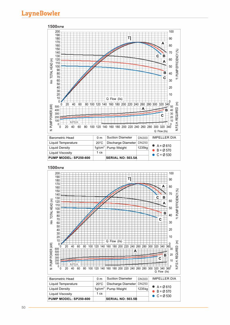
10
20
30
4
50
60
70
80
90
100
A
B
C
A
B
C
0
40
0
10
20
30
0100200300400500600
A
B
C
A
B
C
1500RPM
0102030405060708090
100110120130140150160170180190200
0 20 40 60 80 100 120 140 160 180 200 220 240 260 280 300 320 340 360
..
..
Hm
TO
TAL
HE
AD
(m)
N P
UM
P P
OW
ER
(kW
)
...
...
P
UM
P E
FFIC
IEN
CY
(%)
N.P
.S.H
. RE
QU
IRE
D (
m)
Q Flow (l/s)
0102030405060708090
100110120130140150160170180190200
0 20 40 60 80 100 120 140 160 180 200 220 240 260 280 300 320 3400
10
20
30
40
50
60
70
80
90
100
0100200300400500
01020304050
A
B
C
A
B
C
0 20 40 60 80 100 120 140 160 180 200 220 240 260 280 300 320 340
Q Flow (l/s)N P
UM
P P
OW
ER
(kW
)H
m T
OTA
L H
EA
D (m
)
...
N.P
.S.H
. RE
QU
IRE
D (
m)
P
UM
P E
FFIC
IEN
CY
(%)
1500RPM
0 20 40 60 80 100 120 140 160 180 200 220 240 260 280 300 320 340 360
Q Flow (l/s)
Q Flow (l/s)
B = Ø 570A = Ø 610
C = Ø 530
1235kg
DN300
DN250
0 m
20°C31g/cm
D�scharge D�ameter
Pump We�ght
SERIAL NO: 503.5B
L�qu�d V�scos�ty
PUMP MODEL: SP250-600
Barometr�c Head
L�qu�d Temperature
L�qu�d Dens�ty
Suct�on D�ameter IMPELLER DIA
1 cs
B = Ø 570A = Ø 610
C = Ø 530
1235kg
DN300
DN250
0 m
20°C31g/cm
D�scharge D�ameter
Pump We�ght
SERIAL NO: 503.5A
L�qu�d V�scos�ty
PUMP MODEL: SP250-600
Barometr�c Head
L�qu�d Temperature
L�qu�d Dens�ty
Suct�on D�ameter IMPELLER DIA
1 cs
N.P.S.H.
N.P.S.H.
50
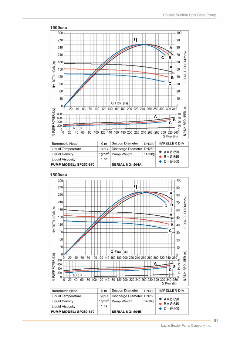
10
20
30
40
50
60
70
80
90
100
30
60
90
120
150
180
210
240
270
300
A
B
C
A
B
C
00
0
10
20
30
40
0
200
400
600
800
A
B
C
AB
C
A
B
C
0 140 360
0 20 40 60 80 100 120 140 160 180 200 220 240 260 280 300 320 340 360
Hm
TO
TAL
HE
AD
(m)
N P
UM
P P
OW
ER
(kW
)
P
UM
P E
FFIC
IEN
CY
(%)
Q Flow (l/s)
N.P
.S.H
. RE
QU
IRE
D (
m)
1500RPM
N.P.S.H.
0
30
60
90
120
150
180
210
240
270
300
0 20 40 60 80 100 120 140 160 180 200 220 240 260 280 300 320 3400
10
20
30
40
50
60
70
80
90
100
0
200
400
600
800
0 20 40 60 80 100 120 140 160 180 200 220 240 260 280 300 320 3400
10
20
30
40
A
B
C
AB
C
A
B
C
1500RPM
Hm
TO
TAL
HE
AD
(m)
N P
UM
P P
OW
ER
(kW
)
N.P
.S.H
. RE
QU
IRE
D (
m)
P
UM
P E
FFIC
IEN
CY
(%)
Q Flow (l/s)
N.P.S.H.
Q Flow (l/s)
Q Flow (l/s)
B = Ø 645A = Ø 690
C = Ø 600
1450kg
DN300
DN250
0 m
20°C31g/cm
D�scharge D�ameter
Pump We�ght
SERIAL NO: 504B
L�qu�d V�scos�ty
PUMP MODEL: SP250-670
Barometr�c Head
L�qu�d Temperature
L�qu�d Dens�ty
Suct�on D�ameter IMPELLER DIA
1 cs
B = Ø 645A = Ø 690
C = Ø 600
1450kg
DN300
DN250
0 m
20°C31g/cm
D�scharge D�ameter
Pump We�ght
SERIAL NO: 504A
L�qu�d V�scos�ty
PUMP MODEL: SP250-670
Barometr�c Head
L�qu�d Temperature
L�qu�d Dens�ty
Suct�on D�ameter IMPELLER DIA
1 cs
20 40 60 80 100 120 160 180 200 220 240 260 280 300 320 340
51
Layne Bowler Pump Company Inc.
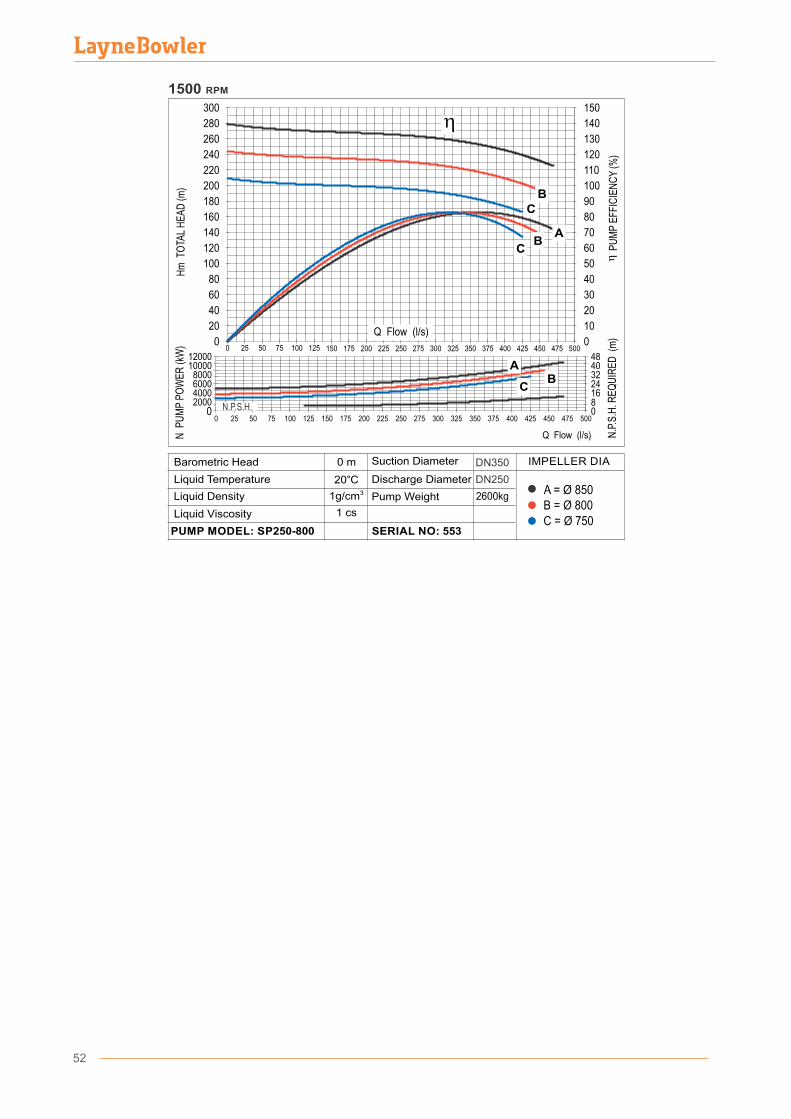
B = Ø 800A = Ø 850
C = Ø 750
2600kg
DN250
DN350
0 m
20°C31g/cm
D�scharge D�ameter
Pump We�ght
SERIAL NO: 553
L�qu�d V�scos�ty
PUMP MODEL: SP250-800
Barometr�c Head
L�qu�d Temperature
L�qu�d Dens�ty
Suct�on D�ameter IMPELLER DIA
1 cs
2000400060008000
1000012000
0
168
24324048
0
N.P
.S.H
. RE
QU
IRE
D (
m)
P
UM
P E
FFIC
IEN
CY
(%)
N P
UM
P P
OW
ER
(kW
)H
m T
OTA
L H
EA
D (m
)
400375350325250 275 300225200175150
150
0
20
30
80
90
100
110
120
130
140
300
0
180
160
140
120
100
80
60
40
20
200
220
240
260
280
1251007550250
Q Flow (l/s)
A
B
C
BC
70
60
50
40
10Q Flow (l/s)
425 450 475 500
N.P.S.H.
AB
C
400375350325250 275 3002252001751501251007550250 425 450 475 500
1500 RPM
52
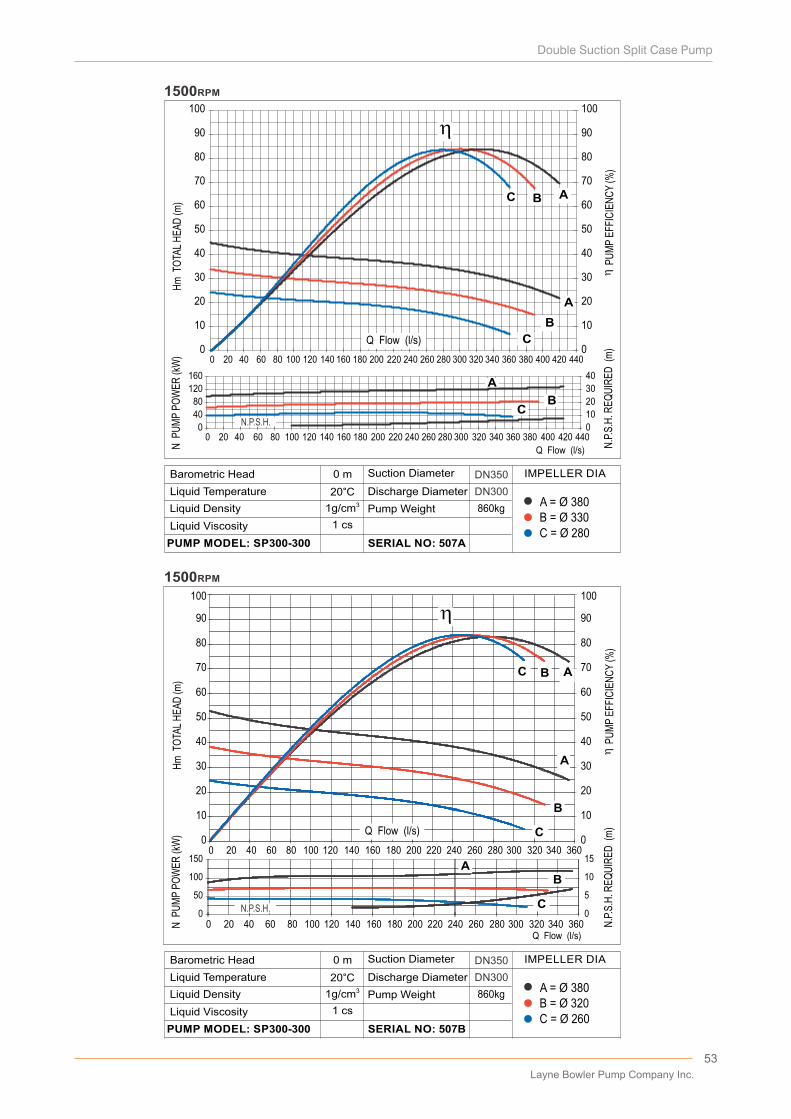
10
20
30
40
50
60
70
80
90
100
10
20
30
40
50
60
70
80
90
100
A
B
C AB
00
0
5
10
15
0
50
100
150
A
B
C
AB
C
AB
C
0 20 40 60 80 100 120 140 160 180 200 220 240 260 280 300 320 340 360
0 20 40 60 80 100 120 140 160 180 200 220 240 260 280 300 320 340 360
Hm
TO
TAL
HE
AD
(m)
N P
UM
P P
OW
ER
(kW
)
P
UM
P E
FFIC
IEN
CY
(%)
Q Flow (l/s)
N.P
.S.H
. RE
QU
IRE
D (
m)
1500RPM
0
10
20
30
40
50
60
70
80
90
100
0
10
20
30
40
50
60
70
80
90
100
0
40
80
120
160
0
10
20
30
40
A
B
C
A
BC
AB
C
0 20 40 60 80 100 120 140 160 180 200 220 240 260 280 300 320 340 360 380 400 420 440
0 20 40 60 80 100 120 140 160 180 200 220 240 260 280 300 320 340 360 380 400 420 440
Hm
TO
TAL
HE
AD
(m)
N P
UM
P P
OW
ER
(kW
)
N.P
.S.H
. RE
QU
IRE
D (
m)
P
UM
P E
FFIC
IEN
CY
(%)
Q Flow (l/s)
1500RPM
Q Flow (l/s)
Q Flow (l/s)
B = Ø 330A = Ø 380
C = Ø 280
860kg
DN350
DN300
0 m
20°C31g/cm
D�scharge D�ameter
Pump We�ght
SERIAL NO: 507A
L�qu�d V�scos�ty
PUMP MODEL: SP300-300
Barometr�c Head
L�qu�d Temperature
L�qu�d Dens�ty
Suct�on D�ameter IMPELLER DIA
1 cs
B = Ø 320A = Ø 380
C = Ø 260
860kg
DN350
DN300
0 m
20°C31g/cm
D�scharge D�ameter
Pump We�ght
SERIAL NO: 507B
L�qu�d V�scos�ty
PUMP MODEL: SP300-300
Barometr�c Head
L�qu�d Temperature
L�qu�d Dens�ty
Suct�on D�ameter IMPELLER DIA
1 cs
N.P.S.H.
N.P.S.H.
53
Layne Bowler Pump Company Inc.
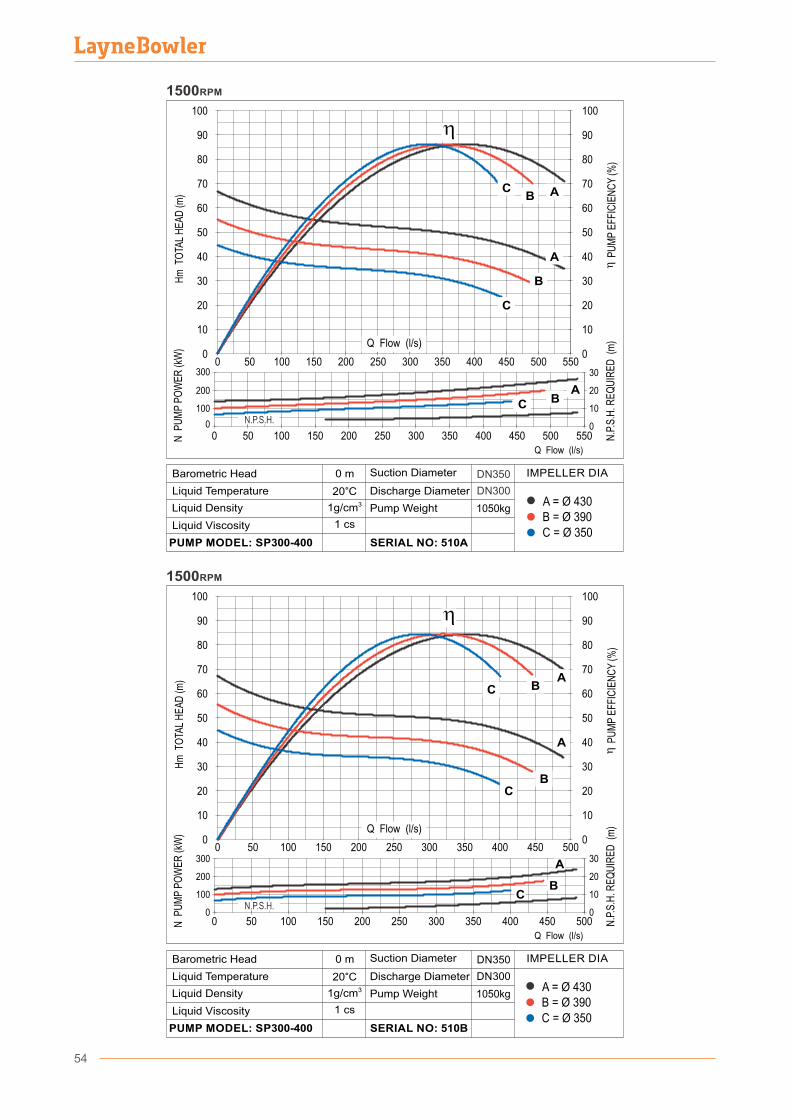
5505004504003503002502001501000 50
5505004504003503002502001501000 50
0
10
20
30
40
50
60
70
80
90
100
1500RPM
0
200
100
300
10
0
20
30
Hm
TO
TAL
HE
AD
(m)
N P
UM
P P
OW
ER
(kW
)
N.P
.S.H
. RE
QU
IRE
D (
m)
P
UM
P E
FFIC
IEN
CY
(%)
Q Flow (l/s)
0
10
20
30
40
50
60
70
80
90
100
ABC
A
B
C
ABC
Q Flow (l/s)
B = Ø 390A = Ø 430
C = Ø 350
DN 350
DN 300
1050kg
0 m
20°C31g/cm
D�scharge D�ameter
Pump We�ght
SERIAL NO: 510B
L�qu�d V�scos�ty
PUMP MODEL: SP300-400
Barometr�c Head
L�qu�d Temperature
L�qu�d Dens�ty
Suct�on D�ameter IMPELLER DIA
1 cs
B = Ø 390A = Ø 430
C = Ø 350
1050kg
DN350
DN300
0 m
20°C31g/cm
D�scharge D�ameter
Pump We�ght
SERIAL NO: 510A
L�qu�d V�scos�ty
PUMP MODEL: SP300-400
Barometr�c Head
L�qu�d Temperature
L�qu�d Dens�ty
Suct�on D�ameter IMPELLER DIA
1 cs
N.P.S.H.
5004504003503002502001501000 50
5004504003503002502001501000 50
0
10
20
30
40
50
60
70
80
90
100
1500RPM
0
200
100
300
10
0
20
30
Hm
TO
TAL
HE
AD
(m)
N P
UM
P P
OW
ER
(kW
)
N.P
.S.H
. RE
QU
IRE
D (
m)
P
UM
P E
FFIC
IEN
CY
(%)
Q Flow (l/s)
0
10
20
30
40
50
60
70
80
90
100
C BA
A
BC
N.P.S.H.
54
CB
A
Q Flow (l/s)
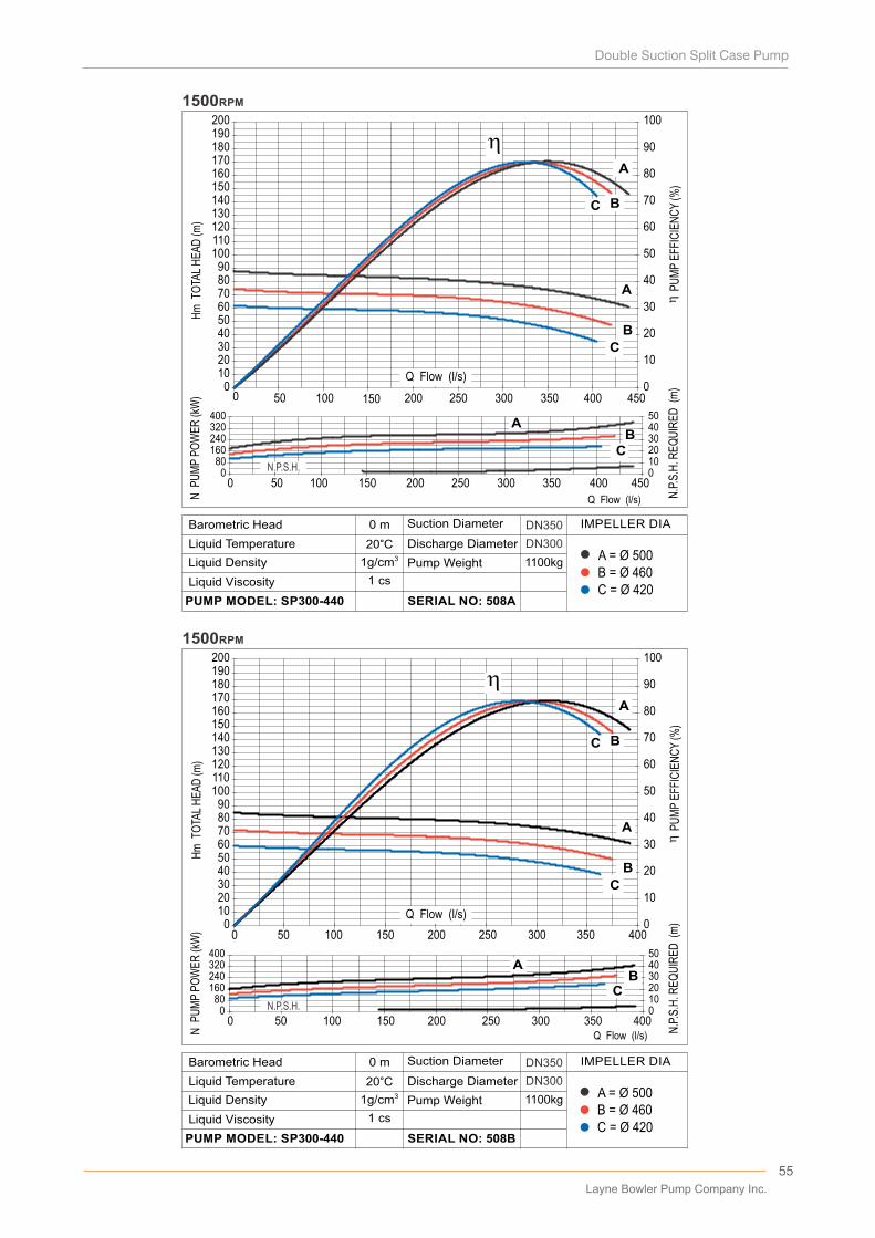
0102030405060708090
100110120130140150160170180190200
0 50 100 150 200 250 300 350 4000
10
20
30
40
50
60
70
80
90
100
080
160240320400
0 50 100 150 200 250 300 350 40001020304050
A
B
C
AB
C
A
B
C
Hm
TO
TAL
HE
AD
(m)
N P
UM
P P
OW
ER
(kW
)
N.P
.S.H
. RE
QU
IRE
D (
m)
P
UM
P E
FFIC
IEN
CY
(%)
Q Flow (l/s)
1500RPM
0102030405060708090
100110120130140150160170180190200
0 50 100 200 250 300 350 400 4501500
10
20
30
40
50
60
70
80
90
100
080
160240320400
0 50 100 150 200 250 300 350 400 45001020304050
A
B
C
AB
C
A
B
C
Q Flow (l/s)N P
UM
P P
OW
ER
(kW
)H
m T
OTA
L H
EA
D (m
)
...
N.P
.S.H
. RE
QU
IRE
D (
m)
P
UM
P E
FFIC
IEN
CY
(%)
1500RPM
Q Flow (l/s)
Q Flow (l/s)
B = Ø 460A = Ø 500
C = Ø 420
1100kg
DN350
DN300
0 m
20°C31g/cm
D�scharge D�ameter
Pump We�ght
SERIAL NO: 508B
L�qu�d V�scos�ty
PUMP MODEL: SP300-440
Barometr�c Head
L�qu�d Temperature
L�qu�d Dens�ty
Suct�on D�ameter IMPELLER DIA
1 cs
B = Ø 460A = Ø 500
C = Ø 420
1100kg
DN350
DN300
0 m
20°C31g/cm
D�scharge D�ameter
Pump We�ght
SERIAL NO: 508A
L�qu�d V�scos�ty
PUMP MODEL: SP300-440
Barometr�c Head
L�qu�d Temperature
L�qu�d Dens�ty
Suct�on D�ameter IMPELLER DIA
1 cs
N.P.S.H.
N.P.S.H.
55
Layne Bowler Pump Company Inc.
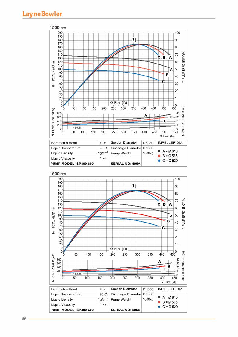
56
0102030405060708090
100110120130140150160170180190200
0 50 100 150 200 250 300 350 400 450 500 5500
10
20
30
40
50
60
70
80
90
100
0
200
400
600
800
0 50 100 150 200 250 300 350 400 450 500 5500
10
20
30
40
A
B
C
A BC
A
B
C
1500RPM
Q Flow (l/s)N P
UM
P P
OW
ER
(kW
)H
m T
OTA
L H
EA
D (m
)
...
N.P
.S.H
. RE
QU
IRE
D (
m)
P
UM
P E
FFIC
IEN
CY
(%)
N.P.S.H.
Q Flow (l/s)
B = Ø 565A = Ø 610
C = Ø 520
1600kg
DN350
DN300
0 m
20°C31g/cm
D�scharge D�ameter
Pump We�ght
SERIAL NO: 505B
L�qu�d V�scos�ty
PUMP MODEL: SP300-600
Barometr�c Head
L�qu�d Temperature
L�qu�d Dens�ty
Suct�on D�ameter IMPELLER DIA
1 cs
B = Ø 565A = Ø 610
C = Ø 520
1600kg
DN350
DN300
0 m
20°C31g/cm
D�scharge D�ameter
Pump We�ght
SERIAL NO: 505A
L�qu�d V�scos�ty
PUMP MODEL: SP300-600
Barometr�c Head
L�qu�d Temperature
L�qu�d Dens�ty
Suct�on D�ameter IMPELLER DIA
1 cs
0102030405060708090
100110120130140150160170180190200
0 50 100 150 200 250 300 350 400 4500
10
20
30
40
50
60
70
80
90
100
0
200
400
600
800
0 50 100 150 200 250 300 350 400 4500
10
20
30
40
A
B
C
A
BC
A
B
C
Hm
TO
TAL
HE
AD
(m)
N P
UM
P P
OW
ER
(kW
)
N.P
.S.H
. RE
QU
IRE
D (
m)
P
UM
P E
FFIC
IEN
CY
(%)
Q Flow (l/s)
1500RPM
N.P.S.H.
Q Flow (l/s)
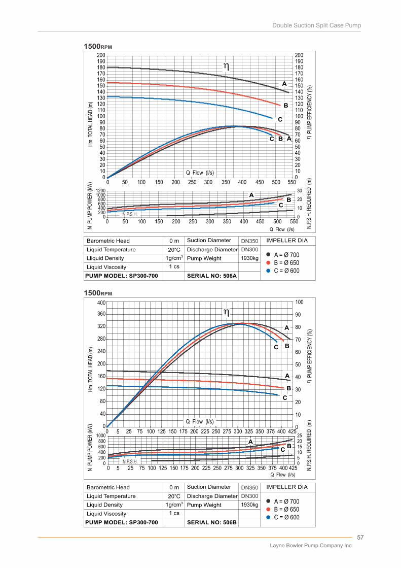
57
0102030405060708090
100110120130140150160170180190200
0 50 100 150 200 250 300 350 400 450 500 5500102030405060708090100110120130140150160170180190200
0200400600800
10001200
0 50 100 150 200 250 300 350 400 450 500 5500
10
20
30
A
B
C
AB
C
A
B
C
N P
UM
P P
OW
ER
(kW
)H
m T
OTA
L H
EA
D (m
)
...
N.P
.S.H
. RE
QU
IRE
D (
m)
P
UM
P E
FFIC
IEN
CY
(%)
1500RPM
10
20
30
40
50
60
70
80
90
100
40
80
120
160
200
240
280
320
360
400
A
B
C
A
B
C
00
0510152025
02004006008001000
A
B
C
BC
A
B
C
0 5 25 75 100 125 150 175 200 225 250 275 300 325 350 375 400 425
0 5 2 5 75 100 125 150 175 200 225 250 275 300 325 350 375 400 425
1500RPM
..
..
Hm
TO
TAL
HE
AD
(m)
N P
UM
P P
OW
ER
(kW
)
...
...
N.P
.S.H
. RE
QU
IRE
D (
m)
P
UM
P E
FFIC
IEN
CY
(%)
A
N.P.S.H.
Q Flow (l/s)
Q Flow (l/s)
Q Flow (l/s)
B = Ø 650A = Ø 700
C = Ø 600
1930kg
DN350
DN300
0 m
20°C31g/cm
D�scharge D�ameter
Pump We�ght
SERIAL NO: 506B
L�qu�d V�scos�ty
PUMP MODEL: SP300-700
Barometr�c Head
L�qu�d Temperature
L�qu�d Dens�ty
Suct�on D�ameter IMPELLER DIA
1 cs
B = Ø 650A = Ø 700
C = Ø 600
1930kg
DN350
DN300
0 m
20°C31g/cm
D�scharge D�ameter
Pump We�ght
SERIAL NO: 506A
L�qu�d V�scos�ty
PUMP MODEL: SP300-700
Barometr�c Head
L�qu�d Temperature
Ll�qu�d Dens�ty
Suct�on D�ameter IMPELLER DIA
1 cs
N.P.S.H.
Q Flow (l/s)
Layne Bowler Pump Company Inc.
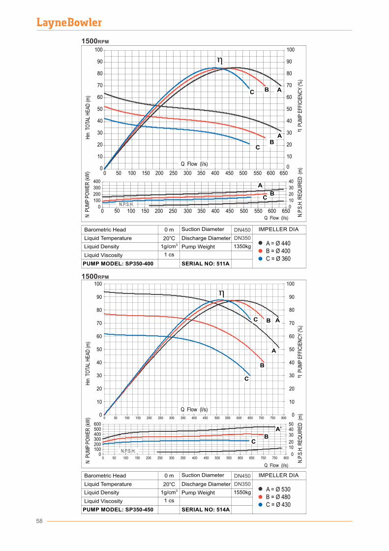
58
0 50 100 150 200 250 300 350 400 450 500 550 600 650 700 750 8000
1020
304050
0100200300400500600
10
0
20
30
40
50
60
70
80
90
100
10
0
20
30
40
50
60
70
80
90
100
0 50 100 150 200 250 300 350 400 450 500 550 600 650 700 750 800
C
C
AB
0
10
20
30
40
50
60
70
80
90
100
0 50 100 150 200 250 300 350 400 450 500 550 600 6500
10
20
30
40
50
60
70
80
90
100
0
100
200
300
400
0
10
20
30
40
AB
C
A
BC
AB
C
0 50 100 150 200 250 300 350 400 450 500 550 600 650
Hm
TO
TAL
HE
AD
(m)
N P
UM
P P
OW
ER
(kW
)
N.P
.S.H
. RE
QU
IRE
D (
m)
1500RPM
1500RPM
Hm
TO
TAL
HE
AD
(m)
N P
UM
P P
OW
ER
(kW
)
N.P
.S.H
. RE
QU
IRE
D (
m)
P
UM
P E
FFIC
IEN
CY
(%)
A
B
A
N.P.S.H.
N.P.S.H.
CB
P
UM
P E
FFIC
IEN
CY
(%)
Q Flow (l/s)
Q Flow (l/s)
B = Ø 480A = Ø 530
C = Ø 430
1550kg
DN450
DN350
0 m
20°C31g/cm
D�scharge D�ameter
Pump We�ght
SERIAL NO: 514A
L�qu�d V�scos�ty
PUMP MODEL: SP350-450
Barometr�c Head
L�qu�d Temperature
L�qu�d Dens�ty
Suct�on D�ameter IMPELLER DIA
1 cs
B = Ø 400A = Ø 440
C = Ø 360
1350kg
DN450
DN350
0 m
20°C31g/cm
D�scharge D�ameter
Pump We�ght
SERIAL NO: 511A
L�qu�d V�scos�ty
PUMP MODEL: SP350-400
Barometr�c Head
L�qu�d Temperature
L�qu�d Dens�ty
Suct�on D�ameter IMPELLER DIA
1 cs
Q Flow (l/s)
Q Flow (l/s)
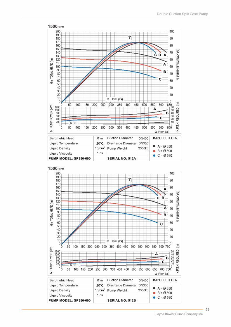
59
1500RPM
0102030405060708090
100110120130140150160170180190200
0 50 100 150 200 250 300 350 400 450 500 550 600 650 700 7500
10
20
30
40
50
60
70
80
90
100
0300600900
12001500
01020304050
A
B
C
AB
C
A
B
C
0 50 100 150 200 250 300 350 400 450 500 550 600 650 700 750
Hm
TO
TAL
HE
AD
(m)
...
N.P
.S.H
. RE
QU
IRE
D (
m)
P
UM
P E
FFIC
IEN
CY
(%)
0102030405060708090
100110120130140150160170180190200
0
10
20
30
40
50
60
70
80
90
100
0200400600800
10001200
0102030405060
A
B
C AB
C
0 50 100 150 200 250 300 350 400 450 500 550 600 650
N P
UM
P P
OW
ER
(kW
)H
m T
OTA
L H
EA
D (m
)
...
N.P
.S.H
. RE
QU
IRE
D (
m)
P
UM
P E
FFIC
IEN
CY
(%)
1500RPM
0 50 100 150 200 250 300 350 400 450 500 550 600 650
AB
C
N P
UM
P P
OW
ER
(kW
)
Q Flow (l/s)
Q Flow (l/s)
Q Flow (l/s)
B = Ø 590A = Ø 650
C = Ø 530
2350kg
DN400
DN350
0 m
20°C31g/cm
D�scharge D�ameter
Pump We�ght
SERIAL NO: 512B
L�qu�d V�scos�ty
PUMP MODEL: SP350-600
Barometr�c Head
L�qu�d Temperature
L�qu�d Dens�ty
Suct�on D�ameter IMPELLER DIA
1 cs
B = Ø 590A = Ø 650
C = Ø 530
2350kg
DN400
DN350
0 m
20°C31g/cm
D�scharge D�ameter
Pump We�ght
SERIAL NO: 512A
L�qu�d V�scos�ty
PUMP MODEL: SP350-600
Barometr�c Head
L�qu�d Temperature
L�qu�d Dens�ty
Suct�on D�ameter IMPELLER DIA
1 cs
N.P.S.H.
N.P.S.H.
Q Flow (l/s)
Layne Bowler Pump Company Inc.
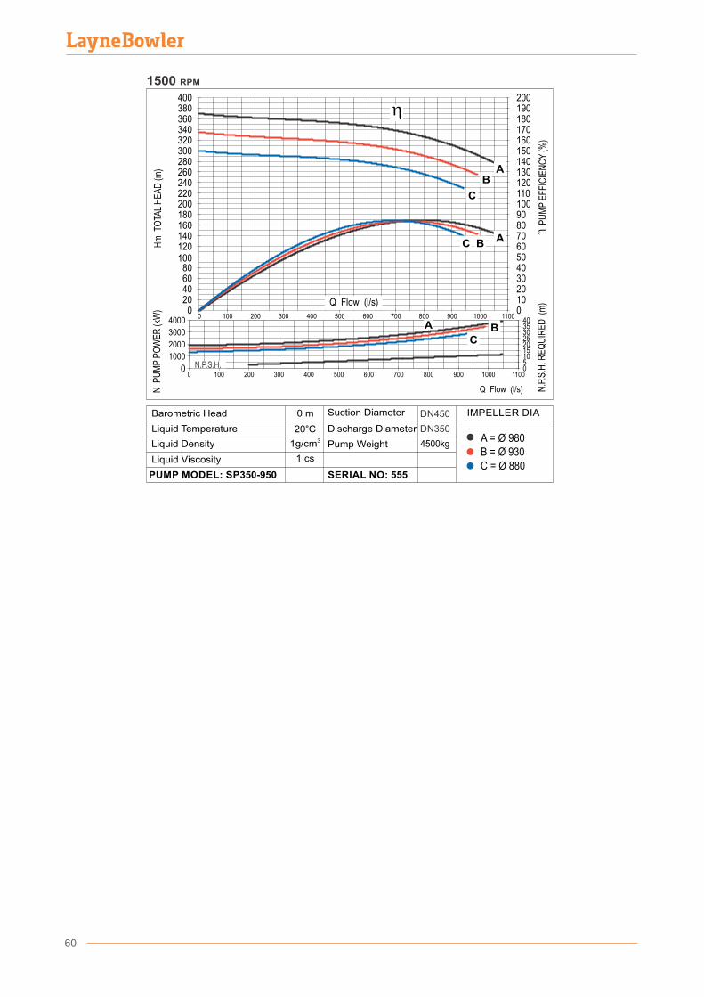
B = Ø 930A = Ø 980
C = Ø 880
4500kg
DN350
DN450
0 m
20°C31g/cm
D�scharge D�ameter
Pump We�ght
SERIAL NO: 555
L�qu�d V�scos�ty
PUMP MODEL: SP350-950
Barometr�c Head
L�qu�d Temperature
L�qu�d Dens�ty
Suct�on D�ameter IMPELLER DIA
1 cs
1000
2000
3000
0
2015
25303540
0
N.P
.S.H
. RE
QU
IRE
D (
m)
P
UM
P E
FFIC
IEN
CY
(%)
N P
UM
P P
OW
ER
(kW
)H
m T
OTA
L H
EA
D (m
)
900800700600500400300
200
0
7080
130140150160170180190
400
0
280260240220200180160140120
300320340360380
2001000
Q Flow (l/s)
12011010090
60
1000 1100
N.P.S.H.
Q Flow (l/s)
9008007006005004003002001000 1000 1100
B
C
A
ABC
BC
A
10080604020
5040302010
105
4000
1500 RPM
60
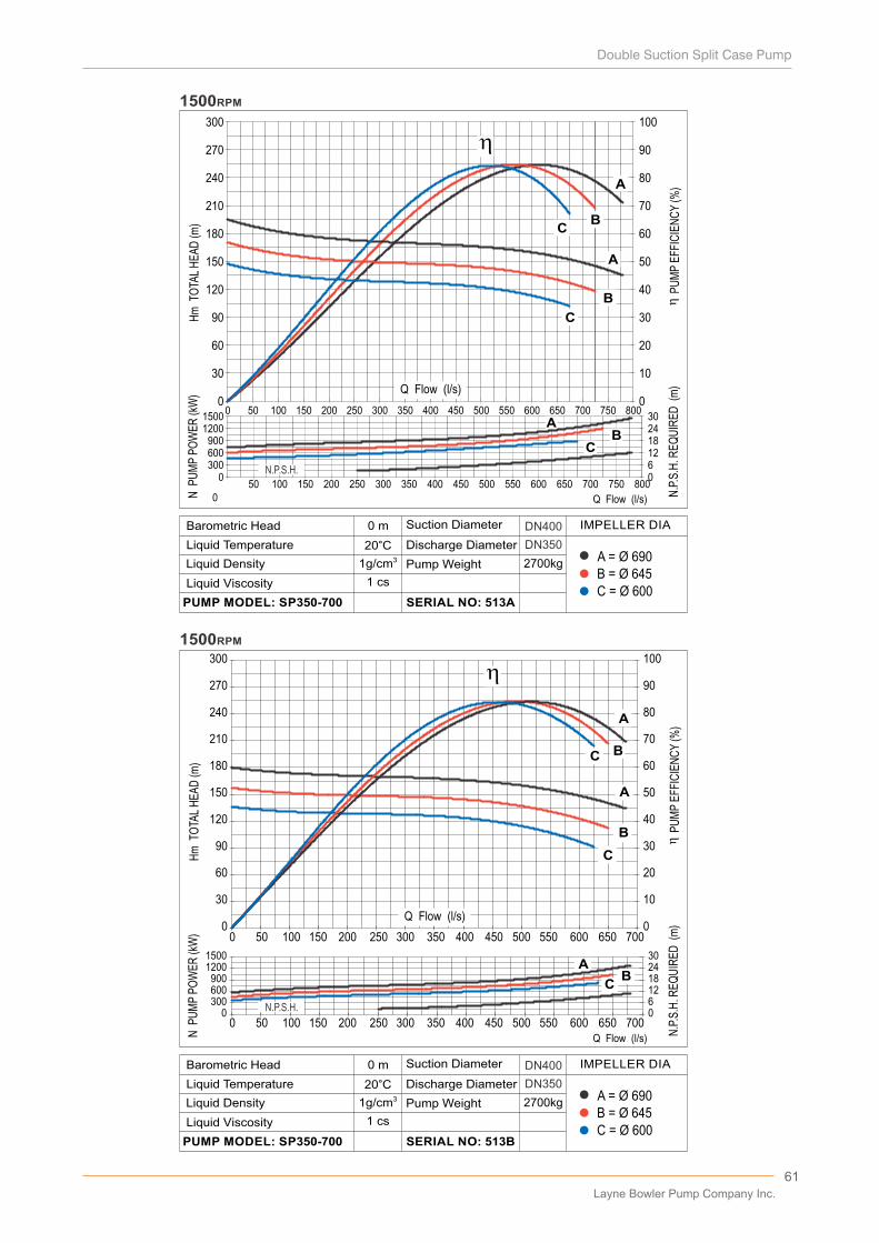
61
B = Ø 645A = Ø 690
C = Ø 600
2700kg
DN400
DN350
0 m
20°C31g/cm
D�scharge D�ameter
Pump We�ght
SERIAL NO: 513B
L�qu�d V�scos�ty
PUMP MODEL: SP350-700
Barometr�c Head
L�qu�d Temperature
L�qu�d Dens�ty
Suct�on D�ameter IMPELLER DIA
1 cs
B = Ø 645A = Ø 690
C = Ø 600
2700kg
DN400
DN350
0 m
20°C31g/cm
D�scharge D�ameter
Pump We�ght
SERIAL NO: 513A
L�qu�d V�scos�ty
PUMP MODEL: SP350-700
Barometr�c Head
L�qu�d Temperature
L�qu�d Dens�ty
Suct�on D�ameter IMPELLER DIA
1 cs
0
30
60
90
120
150
180
210
240
270
300
0
10
20
30
40
50
60
70
80
90
100
300600900
12001500
0
126
182430
Hm
TO
TAL
HE
AD
(m)
N P
UM
P P
OW
ER
(kW
)
N.P
.S.H
. RE
QU
IRE
D (
m)
P
UM
P E
FFIC
IEN
CY
(%)
1500RPM
800750700650600550500450400350300250200150100500
800750700650600550500450400350300250200150100500
0
CB
A
A
B
C
AB
C
0
30
60
90
120
150
180
210
240
270
300
0 50 100 150 200 250 300 350 400 450 500 550 600 650 7000
10
20
30
40
50
60
70
80
90
100
0300600900
12001500
0612182430
A
B
C
AB
A
B
C
1500RPM
0 50 100 150 200 250 300 350 400 450 500 550 600 650 700
Hm
TO
TAL
HE
AD
(m)
N P
UM
P P
OW
ER
(kW
)
N.P
.S.H
. RE
QU
IRE
D (
m)
P
UM
P E
FFIC
IEN
CY
(%)
C
N.P.S.H.
N.P.S.H.
Q Flow (l/s)
Q Flow (l/s)
Q Flow (l/s)
Q Flow (l/s)
Layne Bowler Pump Company Inc.

62
1500RPM
0 100 200 300 400 500 600 700 800 900 1000
N P
UM
P P
OW
ER
(kW
)H
m T
OTA
L H
EA
D (m
)
...
N.P
.S.H
. RE
QU
IRE
D (
m)
P
UM
P E
FFIC
IEN
CY
(%)
0
20
40
60
80
100
120
140
160
180
200
220
0
10
20
30
40
50
60
70
80
90
100
110
A
B
C
A
B
C
0200400600800
1000
01020304050
A BC
A
0 100 200 300 400 500 600 700 800 900 1000
0
20
40
60
80
100
120
140
160
180
200
220
0 50 100 150 200 250 300 350 400 450 500 550 600 650 700 750 8000
10
20
30
40
50
60
70
80
90
100
110
A
B
C
A
B
C
1500RPM
0200400600800
1000
01020304050
A
BC
0 50 100 150 200 250 300 350 400 450 500 550 600 650 700 750 800
Hm
TO
TAL
HE
AD
(m)
N P
UM
P P
OW
ER
(kW
)
N.P
.S.H
. RE
QU
IRE
D (
m)
P
UM
P E
FFIC
IEN
CY
(%)
Q Flow (l/s)
Q Flow (l/s)
B = Ø 530A = Ø 570
C = Ø 490
2400kg
DN500
DN400
B = Ø 530A = Ø 570
C = Ø 490
2400kg
DN500
DN400
0 m
20°C31g/cm
D�scharge D�ameter
Pump We�ght
SERIAL NO: 523B
L�qu�d V�scos�ty
PUMP MODEL: SP400-500
Barometr�c Head
L�qu�d Temperature
L�qu�d Dens�ty
Suct�on D�ameter IMPELLER DIA
1 cs
N.P.S.H.
N.P.S.H.
0 m
20°C31g/cm
D�scharge D�ameter
Pump We�ght
SERIAL NO: 523C
L�qu�d V�scos�ty
PUMP MODEL: SP400-500
Barometr�c Head
L�qu�d Temperature
L�qu�d Dens�ty
Suct�on D�ameter IMPELLER DIA
1 cs
Q Flow (l/s)
Q Flow (l/s)
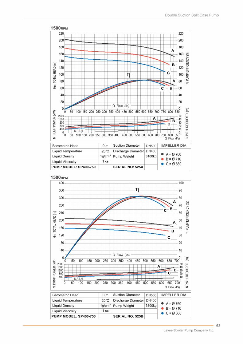
63
...
0
20
40
60
80
100
120
140
160
180
200
220
0 50 100 150 200 250 300 350 400 450 500 550 600 650 700 750 800 8500
20
40
60
80
100
120
140
160
180
200
220
A
B
C
A
B
C
0400800
120016002000
01020304050
AB
C
0 50 100 150 200 250 300 350 400 450 500 550 600 650 700 750 800 850
N P
UM
P P
OW
ER
(kW
)H
m T
OTA
L H
EA
D (m
)
...
N.P
.S.H
. RE
QU
IRE
D (
m)
P
UM
P E
FFIC
IEN
CY
(%)
1500RPM
0
40
80
120
160
200
240
280
320
360
400
0 50 100 150 200 250 300 350 400 450 500 550 600 650 7000
10
20
30
40
50
60
70
80
90
100
0400800
120016002000
01020304050
A
B
C
AB
C
A
B
C
0 50 100 150 200 250 300 350 400 450 500 550 600 650 700
N P
UM
P P
OW
ER
(kW
)H
m T
OTA
L H
EA
D (m
)
...
N.P
.S.H
. RE
QU
IRE
D (
m)
P
UM
P E
FFIC
IEN
CY
(%)
1500RPM
N.P.S.H.
N.P.S.H.
Q Flow (l/s)
Q Flow (l/s)
Q Flow (l/s)
B = Ø 710A = Ø 760
C = Ø 660
3100kg
DN500
DN400
0 m
20°C31g/cm
D�scharge D�ameter
Pump We�ght
SERIAL NO: 525B
L�qu�d V�scos�ty
PUMP MODEL: SP400-750
Barometr�c Head
L�qu�d Temperature
L�qu�d Dens�ty
Suct�on D�ameter IMPELLER DIA
1 cs
B = Ø 710A = Ø 760
C = Ø 660
3100kg
DN500
DN400
0 m
20°C31g/cm
D�scharge D�ameter
Pump We�ght
SERIAL NO: 525A
L�qu�d V�scos�ty
PUMP MODEL: SP400-750
Barometr�c Head
L�qu�d Temperature
L�qu�d Dens�ty
Suct�on D�ameter IMPELLER DIA
1 cs
Q Flow (l/s)
Layne Bowler Pump Company Inc.
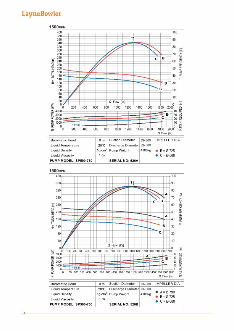
64
N P
UM
P P
OW
ER
(kW
)
1500RPM
0
40
80
120
160
200
240
280
320
360
400
0 100 200 300 400 500 600 700 800 900 1000 1100 1200 1300 1400 1500 160017000
10
20
30
40
50
60
70
80
90
100
A
B
C
A
B
C
N P
UM
P P
OW
ER
(kW
)H
m T
OTA
L H
EA
D (m
)
...
N.P
.S.H
. RE
QU
IRE
D (
m)
P
UM
P E
FFIC
IEN
CY
(%)
0
1000
2000
3000
4000
0
10
20
30
40A
BC
0 100 200 300 400 500 600 700 800 900 1000 1100 1200 1300 1400 1500 1600 1700
020406080
100120140160180200220240260280300320340360380400
0 200 400 600 800 1000 1200 1400 1600 1800 2000
01000200030004000
BC
0
10
20
30
40
50
60
70
80
90
100
010203040
0 200 400 600 800 1000 1200 1400 1600 1800 2000
Hm
TO
TAL
HE
AD
(m)
N.P
.S.H
. RE
QU
IRE
D (
m)
P
UM
P E
FFIC
IEN
CY
(%)
1500RPM
Q Flow (l/s)
Q Flow (l/s)
B = Ø 725A = Ø 790
C = Ø 660
4100kg
DN600
DN500
0 m
20°C31g/cm
D�scharge D�ameter
Pump We�ght
SERIAL NO: 526B
L�qu�d V�scos�ty
PUMP MODEL: SP500-750
Barometr�c Head
L�qu�d Temperature
L�qu�d Dens�ty
Suct�on D�ameter IMPELLER DIA
1 cs
4100kg
DN600
DN500
B = Ø 725C = Ø 660
0 m
20°C31g/cm
D�scharge D�ameter
Pump We�ght
SERIAL NO: 526A
L�qu�d V�scos�ty
PUMP MODEL: SP500-750
Barometr�c Head
L�qu�d Temperature
L�qu�d Dens�ty
Suct�on D�ameter IMPELLER DIA
1 cs
N.P.S.H.
N.P.S.H.
B
C B
C
Q Flow (l/s)
Q Flow (l/s)
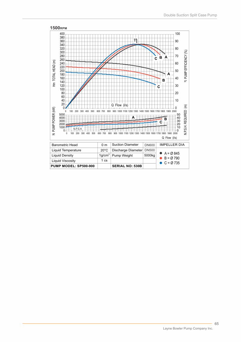
N P
UM
P P
OW
ER
(kW
)
010002000300040005000
01020304050
A BC
020406080
100120140160180200220240260280300320340360380400
0 100 200 300 400 500 600 700 800 900 1000 1100 1200 1300 1400 1500 1600 1700 1800 1900 20000
10
20
30
40
50
60
70
80
90
100
A
B
C AB
C
1500RPM
0 100 200 300 400 500 600 700 800 900 1000 1100 1200 1300 1400 1500 1600 1700 1800 1900 2000
Hm
TO
TAL
HE
AD
(m)
N.P
.S.H
. RE
QU
IRE
D (
m)
P
UM
P E
FFIC
IEN
CY
(%)
N.P.S.H.
Q Flow (l/s)
B = Ø 790A = Ø 845
C = Ø 735
5000kg
DN600
DN500
0 m
20°C31g/cm
D�scharge D�ameter
Pump We�ght
SERIAL NO: 530B
L�qu�d V�scos�ty
PUMP MODEL: SP500-900
Barometr�c Head
L�qu�d Temperature
L�qu�d Dens�ty
Suct�on D�ameter IMPELLER DIA
1 cs
Q Flow (l/s)
65Layne Bowler Pump Company Inc.
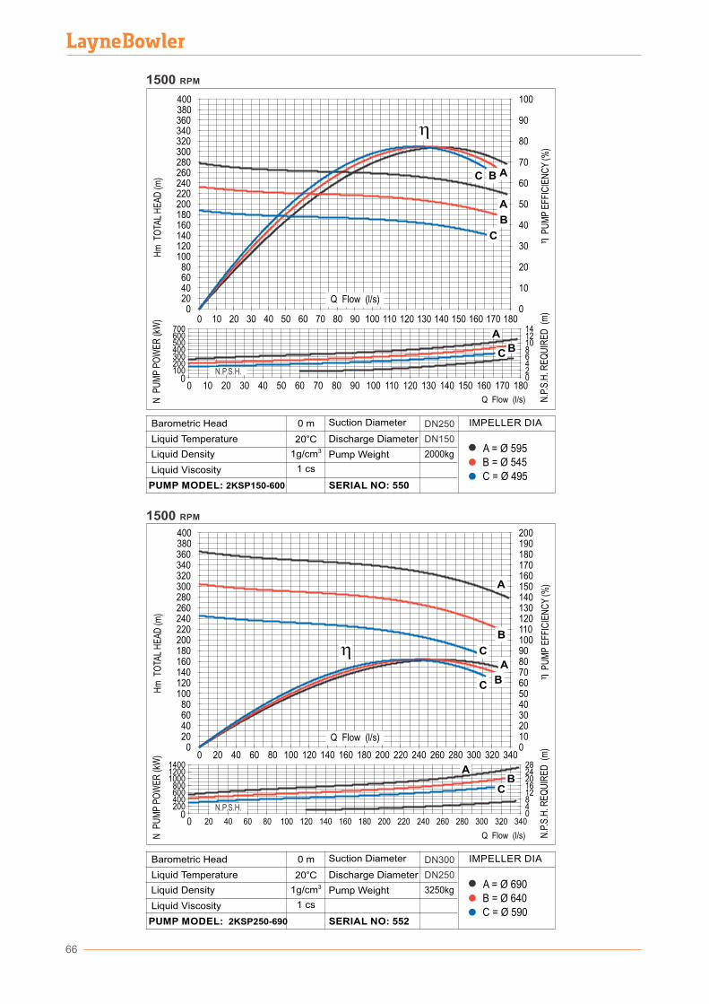
66
B = Ø 640A = Ø 690
C = Ø 590
3250kg
DN250
DN300
0 m
20°C31g/cm
D�scharge D�ameter
Pump We�ght
SERIAL NO: 552
L�qu�d V�scos�ty
PUMP MODEL: 2KSP250-690
Barometr�c Head
L�qu�d Temperature
L�qu�d Dens�ty
Suct�on D�ameter IMPELLER DIA
1 cs
B = Ø 545A = Ø 595
C = Ø 495
2000kg
DN250
DN150
0 m
20°C31g/cm
D�scharge D�ameter
Pump We�ght
SERIAL NO: 550
L�qu�d V�scos�ty
PUMP MODEL: 2KSP150-600
Barometr�c Head
L�qu�d Temperature
L�qu�d Dens�ty
Suct�on D�ameter IMPELLER DIA
1 cs
200100
300400500600700
0
642
8101214
0
N.P
.S.H
. RE
QU
IRE
D (
m)
P
UM
P E
FFIC
IEN
CY
(%)
N P
UM
P P
OW
ER
(kW
)H
m T
OTA
L H
EA
D (m
)
1801701601501401301201101009080706050403020100
360340320300280
400380
0
260240220200180160140120100
80604020
100
90
80
70
60
50
40
30
20
10
0
1500 RPM
C B A
A
B
C
1801701601501401301201101009080706050 403020100
N.P.S.H.
A
BC
1500 RPM
400200
600800
100012001400
0
1284
16202428
00
N.P
.S.H
. RE
QU
IRE
D (
m)
P
UM
P E
FFIC
IEN
CY
(%)
N P
UM
P P
OW
ER
(kW
)H
m T
OTA
L H
EA
D (m
)
340320300280260240220200180160140120100806040200
220 240 260 280 300 320 34020018016014012010080604020
360340320300280
400380
0
260240220200180160140120100
80604020
180170160150140
200190
0
130120110100908070605040302010
A
B
C
A
BC
N.P.S.H.
AB
C
Q Flow (l/s)
Q Flow (l/s)
Q Flow (l/s)
Q Flow (l/s)
67
PerformanceCurves
1000rpm
Layne Bowler Pump Company Inc.
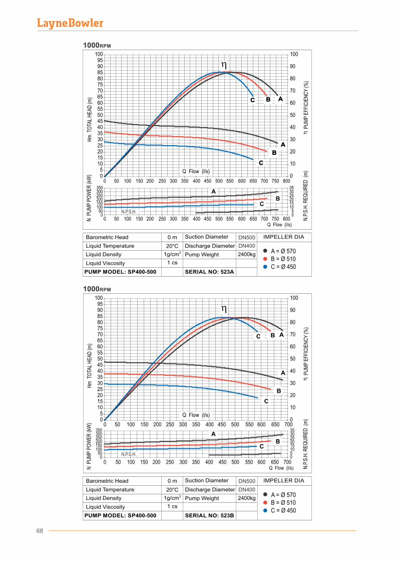
68
05
101520253035404550556065707580859095
100
0 50 100 150 200 250 300 350 400 450 500 550 600 650 700 750 8000
10
20
30
40
50
60
70
80
90
100
AA
BB
CC AABB
CC
050
100150200250300350
05
101520253035
AB
C
0 50 100 150 200 250 300 350 400 450 500 550 600 650 700 750 800
Hm
TO
TAL
HE
AD
(m)
N P
UM
P P
OW
ER
(kW
)
N.P
.S.H
. RE
QU
IRE
D (
m)
P
UM
P E
FFIC
IEN
CY
(%)
1000RPM
1000RPM
05
101520253035404550556065707580859095
100
0 50 100 150 200 250 300 350 400 450 500 550 600 650 7000
10
20
30
40
50
60
70
80
90
100
A
B
C AB
C
050
100150200250300350
05101520253035
AB
C
0 50 100 150 200 250 300 350 400 450 500 550 600 650 700
N P
UM
P P
OW
ER
(kW
)H
m T
OTA
L H
EA
D (m
)
...
N.P
.S.H
. RE
QU
IRE
D (
m)
P
UM
P E
FFIC
IEN
CY
(%)
Q Flow (l/s)
Q Flow (l/s)
B = Ø 510A = Ø 570
C = Ø 450
2400kg
DN500
DN400
0 m
20°C31g/cm
D�scharge D�ameter
Pump We�ght
SERIAL NO: 523B
L�qu�d V�scos�ty
PUMP MODEL: SP400-500
Barometr�c Head
L�qu�d Temperature
L�qu�d Dens�ty
Suct�on D�ameter IMPELLER DIA
1 cs
B = Ø 510A = Ø 570
C = Ø 450
2400kg
DN500
DN400
0 m
20°C31g/cm
D�scharge D�ameter
Pump We�ght
SERIAL NO: 523A
L�qu�d V�scos�ty
PUMP MODEL: SP400-500
Barometr�c Head
L�qu�d Temperature
L�qu�d Dens�ty
Suct�on D�ameter IMPELLER DIA
1 cs
N.P.S.H.
N.P.S.H.
Q Flow (l/s)
Q Flow (l/s)

69
1000RPM
0102030405060708090
100110120130140150160170180190200
0
10
20
30
40
50
60
70
80
90
100
A
B
C AB
C
0100200300400500600700
05101520253035
A
BC
0 50 100 150 200 250 300 350 400 450 500 550 600
Hm
TO
TAL
HE
AD
(m)
N P
UM
P P
OW
ER
(kW
)
N.P
.S.H
. RE
QU
IRE
D (
m)
P
UM
P E
FFIC
IEN
CY
(%)
0 50 100 150 200 250 300 350 400 450 500 550 600
1000RPM
20
30
40
50
60
70
80
90
100
0
10
40
60
80
100
120
140
160
180
200
0
20
0 50 100 150 200 250 300 350 400 450
A
B
C
A
B
C
N.P
.S.H
. RE
QU
IRE
D (
m)
0510152025
0 50 100 150 200 250 300 350 400 4500
100200300400500
BC
N P
UM
P P
OW
ER
(kW
)H
m T
OTA
L H
EA
D (m
)
P
UM
P E
FFIC
IEN
CY
(%)
A
Q Flow (l/s)
Q Flow (l/s)
Q Flow (l/s)
B = Ø 710A = Ø 760
C = Ø 660
3100kg
DN500
DN400
0 m
20°C31g/cm
D�scharge D�ameter
Pump We�ght
SERIAL NO: 525B
L�qu�d V�scos�ty
PUMP MODEL: SP400-750
Barometr�c Head
L�qu�d Temperature
Lqu�d Dens�ty
Suct�on D�ameter IMPELLER DIA
1 cs
B = Ø 710A = Ø 760
C = Ø 660
3100kg
DN500
DN400
0 m
20°C31g/cm
D�scharge D�ameter
Pump We�ght
SERIAL NO: 525A
L�qu�d v�scos�ty
PUMP MODEL: SP400-750
Barometr�c Head
L�qu�d Temperature
l�qu�d Dens�ty
Suct�on D�ameter IMPELLER DIA
1 cs
N.P.S.H.
N.P.S.H.
Q Flow (l/s)
Layne Bowler Pump Company Inc.
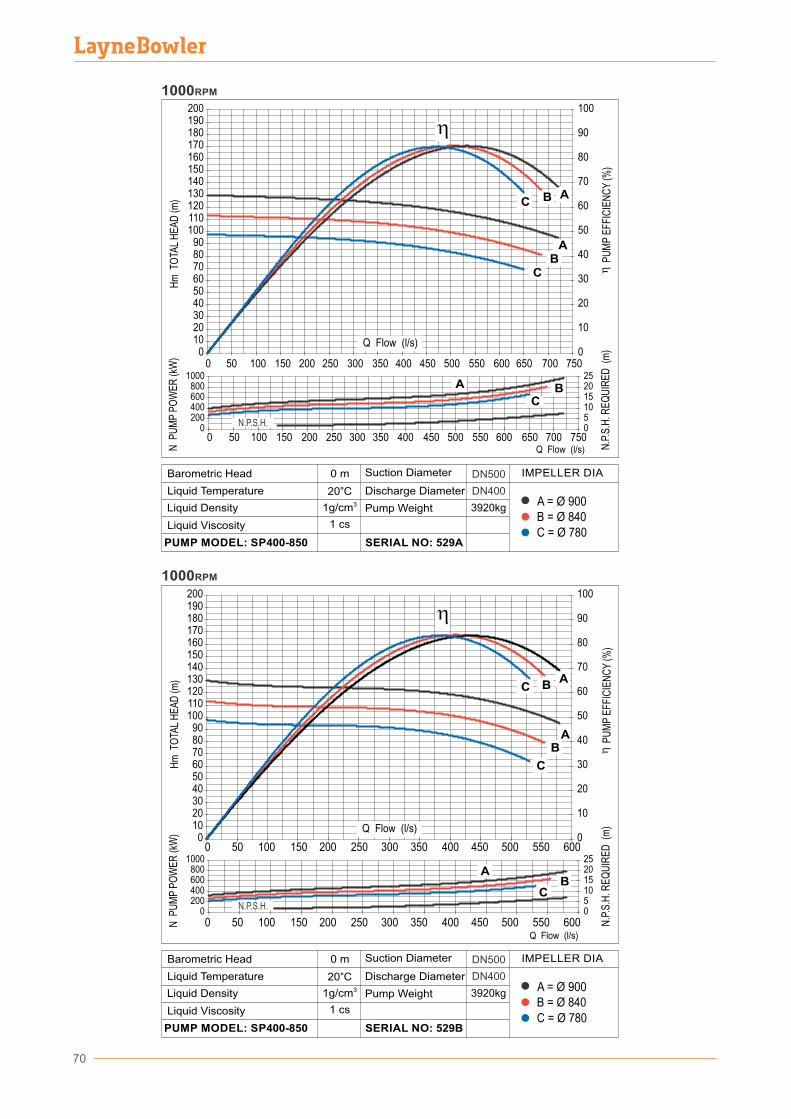
0102030405060708090
100110120130140150160170180190200
0 50 100 150 200 250 300 350 400 450 500 550 600 650 700 7500
10
20
30
40
50
60
70
80
90
100
AB
AB
C
Hm
TO
TAL
HE
AD
(m)
...
N.P
.S.H
. RE
QU
IRE
D (
m)
P
UM
P E
FFIC
IEN
CY
(%)
0200400600800
1000
0 50 100 150 200 250 300 350 400 450 500 550 600 650 700 7500510152025
A BC
N P
UM
P P
OW
ER
(kW
)
1000RPM
C
0200400600800
1000
0510152025
AB
C
0102030405060708090
100110120130140150160170180190200
0 50 100 150 200 250 300 350 400 450 500 550 6000
10
20
30
40
50
60
70
80
90
100
AB
CA
B
CHm
TO
TAL
HE
AD
(m)
N P
UM
P P
OW
ER
(kW
)
N.P
.S.H
. RE
QU
IRE
D (
m)
P
UM
P E
FFIC
IEN
CY
(%)
0 50 100 150 200 250 300 350 400 450 500 550 600
1000RPM
Q Flow (l/s)
Q Flow (l/s)
Q Flow (l/s)
B = Ø 840A = Ø 900
C = Ø 780
3920kg
DN500
DN400
0 m
20°C31g/cm
D�scharge D�ameter
Pump We�ght
SERIAL NO: 529B
L�qu�d V�scos�ty
PUMP MODEL: SP400-850
Barometr�c Head
L�qu�d Temperature
L�qu�d Dens�ty
Suct�on D�ameter IMPELLER DIA
1 cs
B = Ø 840A = Ø 900
C = Ø 780
3920kg
DN500
DN400
0 m
20°C31g/cm
D�scharge D�ameter
Pump We�ght
SERIAL NO: 529A
L�qu�d V�scos�ty
PUMP MODEL: SP400-850
Barometr�c Head
L�qu�d Temperature
L�qu�d Dens�ty
Suct�on D�ameter IMPELLER DIA
1 cs
N.P.S.H.
N.P.S.H.
Q Flow (l/s)
70
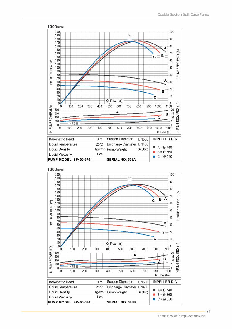
71
0102030405060708090
100110120130140150160170180190200
0 100 200 300 400 500 600 700 800 900 1000 11000
10
20
30
40
50
60
70
80
90
100
A
B
C
A
B
C
Hm
TO
TAL
HE
AD
(m)
...
N.P
.S.H
. RE
QU
IRE
D (
m)
P
UM
P E
FFIC
IEN
CY
(%)
0
200
400
600
800
0
5
10
15
20A
BC
0 100 200 300 400 500 600 700 800 900 1000 1100
N P
UM
P P
OW
ER
(kW
)
1000RPM
0102030405060708090
100110120130140150160170180190200
0 100 200 300 400 500 600 700 800 9000
10
20
30
40
50
60
70
80
90
100
A
B
CAB
C
0
200
400
600
800
0
5
10
15
20A
BC
0 100 200 300 400 500 600 700 800 900
Hm
TO
TAL
HE
AD
(m)
N P
UM
P P
OW
ER
(kW
)
N.P
.S.H
. RE
QU
IRE
D (
m)
P
UM
P E
FFIC
IEN
CY
(%)
1000RPM
Q Flow (l/s)
Q Flow (l/s)
Q Flow (l/s)
B = Ø 660A = Ø 740
C = Ø 580
3750kg
DN500
DN400
0 m
20°C31g/cm
D�scharge D�ameter
Pump We�ght
SERIAL NO: 528B
L�qu�d V�scos�ty
PUMP MODEL: SP400-670
Barometr�c Head
L�qu�d Temperature
L�qu�d Dens�ty
Suct�on D�ameter IMPELLER DIA
1 cs
B = Ø 660A = Ø 740
C = Ø 580
3750kg
DN500
DN400
0 m
20°C31g/cm
D�scharge D�ameter
Pump We�ght
SERIAL NO: 528A
L�qu�d V�scos�ty
PUMP MODEL: SP400-670
Barometr�c Head
L�qu�d Temperature
L�qu�d Dens�ty
Suct�on D�ameter IMPELLER DIA
1 cs
N.P.S.H.
N.P.S.H.
Q Flow (l/s)
Layne Bowler Pump Company Inc.
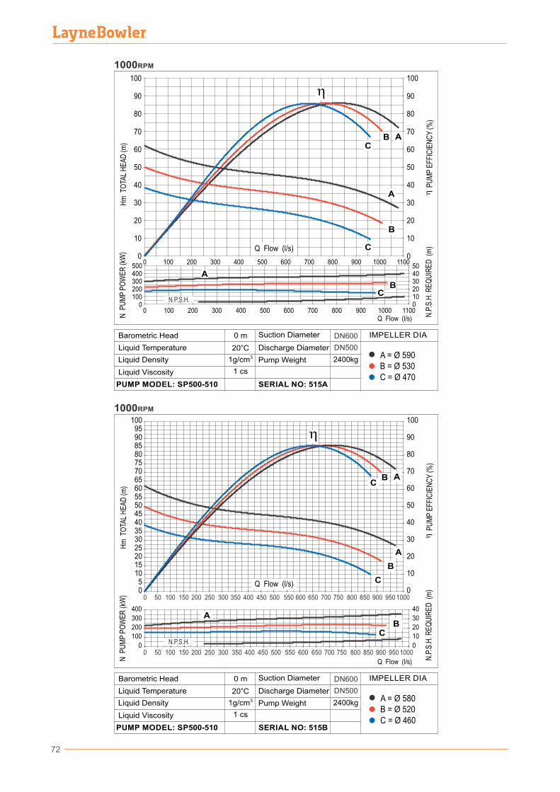
72
B = Ø 520A = Ø 580
C = Ø 460
2400kg
DN600
DN500
B = Ø 530A = Ø 590
C = Ø 470
2400kg
DN600
DN500
0 m
20°C31g/cm
D�scharge D�ameter
Pump We�ght
SERIAL NO: 515A
L�qu�d V�scos�ty
PUMP MODEL: SP500-510
Barometr�c Head
L�qu�d Temperature
L�qu�d Dens�ty
Suct�on D�ameter IMPELLER DIA
1 cs
05
101520253035404550556065707580859095
100
0 50 100 150 200 250 300 350 400 450 500 550 600 650 700 750 800 850 900 950 10000
10
20
30
40
50
60
70
80
90
100
0
100
200
300
400
0
10
20
30
40
A
B
C
AB
C
AB
C
0 50 100 150 200 250 300 350 400 450 500 550 600 650 700 750 800 850 900 950 1000
Hm
TO
TAL
HE
AD
(m)
N P
UM
P P
OW
ER
(kW
)
N.P
.S.H
. RE
QU
IRE
D (
m)
P
UM
P E
FFIC
IEN
CY
(%)
1000RPM
N.P.S.H.
0
10
20
30
40
50
60
70
80
90
100
100200300400500
0
2010
304050
Hm
TO
TAL
HE
AD
(m)
N P
UM
P P
OW
ER
(kW
)
N.P
.S.H
. RE
QU
IRE
D (
m)
P
UM
P E
FFIC
IEN
CY
(%)
1000RPM
110010009008007006005004003002001000
0
BC
A
A
B
C
BC
A
0
10
20
30
40
50
60
70
80
90
100
110010009008007006005004003002001000
N.P.S.H.
0 m
20°C31g/cm
D�scharge D�ameter
Pump We�ght
SERIAL NO: 515B
L�qu�d V�scos�ty
PUMP MODEL: SP500-510
Barometr�c Head
L�qu�d Temperature
L�qu�d Dens�ty
Suct�on D�ameter IMPELLER DIA
1 cs
Q Flow (l/s)
Q Flow (l/s)
Q Flow (l/s)
Q Flow (l/s)
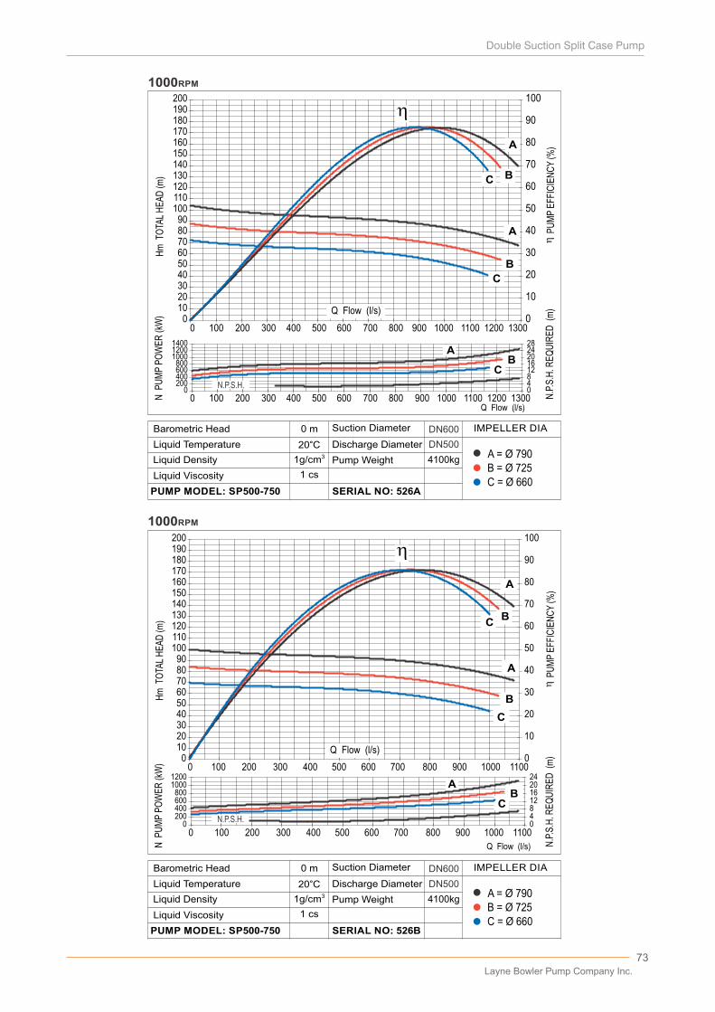
73
Hm
TO
TAL
HE
AD
(m)
...
N.P
.S.H
. RE
QU
IRE
D (
m)
P
UM
P E
FFIC
IEN
CY
(%)
0102030405060708090
100110120130140150160170180190200
0 100 200 300 400 500 600 700 800 900 1000 11000
10
20
30
40
50
60
70
80
90
100
A
B
C
A
0200400600800
10001200
04812162024
AB
C
B
C
0 100 200 300 400 500 600 700 800 900 1000 1100
N P
UM
P P
OW
ER
(kW
)
1000RPM
0200400600800
100012001400
0 100 200 300 400 500 600 700 800 900 1000 1100 1200 13000481216202428
AB
C
0102030405060708090
100110120130140150160170180190200
0
10
20
30
40
50
60
70
80
90
100
A
B
C
A
B
C
0 100 200 300 400 500 600 700 800 900 1000 1100 1200 1300
Hm
TO
TAL
HE
AD
(m)
N P
UM
P P
OW
ER
(kW
)
N.P
.S.H
. RE
QU
IRE
D (
m)
P
UM
P E
FFIC
IEN
CY
(%)
1000RPM
Q Flow (l/s)
Q Flow (l/s)
B = Ø 725A = Ø 790
C = Ø 660
4100kg
DN500
DN600
0 m
20°C31g/cm
D�scharge D�ameter
Pump We�ght
SERIAL NO: 526B
L�qu�d V�scos�ty
PUMP MODEL: SP500-750
Barometr�c Head
L�qu�d Temperature
L�qu�d Dens�ty
Suct�on D�ameter IMPELLER DIA
1 cs
B = Ø 725A = Ø 790
C = Ø 660
4100kg
DN500
DN600
0 m
20°C31g/cm
D�scharge D�ameter
Pump We�ght
SERIAL NO: 526A
L�qu�d V�scos�ty
PUMP MODEL: SP500-750
Barometr�c Head
L�qu�d Temperature
L�qu�d Dens�ty
Suct�on D�ameter IMPELLER DIA
1 cs
N.P.S.H.
N.P.S.H.
Q Flow (l/s)
Q Flow (l/s)
Layne Bowler Pump Company Inc.
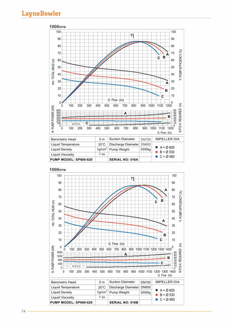
74
B = Ø 530A = Ø 600
C = Ø 460
DN 700
DN 600
3200kg
0 m
20°C31g/cm
D�scharge D�ameter
Pump We�ght
SERIAL NO: 516B
L�qu�d V�scos�ty
PUMP MODEL: SP600-620
Barometr�c Head
L�qu�d Temperature
L�qu�d Dens�ty
Suct�on D�ameter IMPELLER DIA
1 cs
B = Ø 530A = Ø 600
C = Ø 460
3200kg
DN700
DN600
0 m
20°C31g/cm
D�scharge D�ameter
Pump We�ght
SERIAL NO: 516A
L�qu�d V�scos�ty
PUMP MODEL: SP600-620
Barometr�c Head
L�qu�d Temperature
L�qu�d Dens�ty
Suct�on D�ameter IMPELLER DIA
1 cs
N P
UM
P P
OW
ER
(kW
)
0 100 200 300 400 500 600 700 800 900 1000 1100 12000
10
20
30
40
50
60
70
80
90
100
0
10
20
30
40
50
60
70
80
90
100
0100200300400500600
0102030405060
A
B
C
AB
C
B
C
N P
UM
P P
OW
ER
(kW
)H
m T
OTA
L H
EA
D (m
)
...
N.P
.S.H
. RE
QU
IRE
D (
m)
P
UM
P E
FFIC
IEN
CY
(%)
0 100 200 300 400 500 600 700 800 900 1000 1100 1200
A
1000RPM
N.P.S.H.
140013001200110010009008007006005004003001000 2000
10
20
30
40
50
60
70
80
90
100
1000RPM
0
400
800
1200
1600
20100
30405060
Hm
TO
TAL
HE
AD
(m)
N.P
.S.H
. RE
QU
IRE
D (
m)
P
UM
P E
FFIC
IEN
CY
(%)
0
10
20
30
40
50
60
70
80
90
100
140013001200110010009008007006005004003001000 200
A
BC
A
B
C
AB
CN.P.S.H.
Q Flow (l/s)
Q Flow (l/s)
Q Flow (l/s)
Q Flow (l/s)

75
0400800
120016002000
0510152025
AB
C
0102030405060708090
100110120130140150160170180190200
0 100 200 300 400 500 600 700 800 900 1000 1100 1200 13000
10
20
30
40
50
60
70
80
90
100
A
B
C
A
B
C
1000RPM
N.P
.S.H
. RE
QU
IRE
D (
m)
P
UM
P E
FFIC
IEN
CY
(%)
N P
UM
P P
OW
ER
(kW
)H
m T
OTA
L H
EA
D (m
)
0 100 200 300 400 500 600 700 800 900 1000 1100 1200 1300
N.P.S.H.
0
400
800
1200
1600
2000
0
5
10
15
20
25
AB
C
0102030405060708090
100110120130140150160170180190200
0 100 200 300 400 500 600 700 800 900 1000 1100 1200 1300 1400 15000
10
20
30
40
50
60
70
80
90
100
AB
C AB
C
0 100 200 300 400 500 600 700 800 900 1000 1100 1200 1300 1400 1500
...
N.P
.S.H
. RE
QU
IRE
D (
m)
P
UM
P E
FFIC
IEN
CY
(%)
N P
UM
P P
OW
ER
(kW
)H
m T
OTA
L H
EA
D (m
)
1000RPM
N.P.S.H.
Q Flow (l/s)
Q Flow (l/s)
Q Flow (l/s)
B = Ø 845A = Ø 910
C = Ø 780
5000kg
DN600
DN500
0 m
20°C31g/cm
D�scharge D�ameter
Pump We�ght
SERIAL NO: 530A
L�qu�d V�scos�ty
PUMP MODEL: SP500-900
Barometr�c Head
L�qu�d Temperature
L�qu�d Dens�ty
Suct�on D�ameter IMPELLER DIA
1 cs
B = Ø 845A = Ø 910
C = Ø 780
5000kg
DN500
DN600
0 m
20°C31g/cm
D�scharge D�ameter
Pump We�ght
SERIAL NO: 530B
L�qu�d V�scos�ty
PUMP MODEL: SP500-900
Barometr�c Head
L�qu�d Temperature
L�qu�d Dens�ty
Suct�on D�ameter IMPELLER DIA
1 cs
Q Flow (l/s)
Layne Bowler Pump Company Inc.
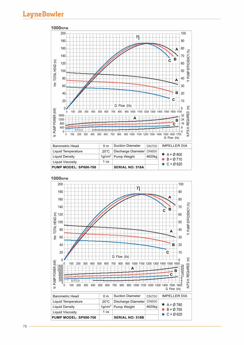
76
Q Flow (l/s)
Q Flow (l/s)
B = Ø 700A = Ø 780
C = Ø 620
4620kg
DN700
DN600
0 m
20°C31g/cm
D�scharge D�ameter
Pump We�ght
SERIAL NO: 518B
L�qu�d V�scos�ty
PUMP MODEL: SP600-700
Barometr�c Head
L�qu�d Temperature
L�qu�d Dens�ty
Suct�on D�ameter IMPELLER DIA
1 cs
B = Ø 710A = Ø 800
C = Ø 620
4620kg
DN700
DN600
0 m
20°C31g/cm
D�scharge D�ameter
Pump We�ght
SERIAL NO: 518A
L�qu�d V�scos�ty
PUMP MODEL: SP600-700
Barometr�c Head
L�qu�d Temperature
L�qu�d Dens�ty
Suct�on D�ameter IMPELLER DIA
1 cs
1000RPM
100
0
20
40
60
80
100
120
140
160
180
200
0 100 200 300 400 500 600 700 800 900 1000 1100 1200 1300 1400 1500 1600 17000
10
20
30
40
50
60
70
80
90
0
400
800
1200
1600
0
8
16
24
32
A
B
C
AB
C
A
B
C
0 100 200 300 400 500 600 700 800 900 1000 1100 1200 1300 1400 1500 1600 1700N P
UM
P P
OW
ER
(kW
)H
m T
OTA
L H
EA
D (m
)
...
N.P
.S.H
. RE
QU
IRE
D (
m)
P
UM
P E
FFIC
IEN
CY
(%)
N.P.S.H.
0
10
20
30
40
50
60
70
80
90
100
400200
800600
100012001400
0
161284
202428
Hm
TO
TAL
HE
AD
(m)
N P
UM
P P
OW
ER
(kW
)
N.P
.S.H
. RE
QU
IRE
D (
m)
P
UM
P E
FFIC
IEN
CY
(%)
1000RPM
16001500140013001200110010006005004003002001000
0
0
20
40
60
80
100
120
140
160
180
200
900800700
16001500140013001200110010006005004003002001000 900800700
A
BC
A
B
C
AB
C
N.P.S.H.
Q Flow (l/s)
Q Flow (l/s)
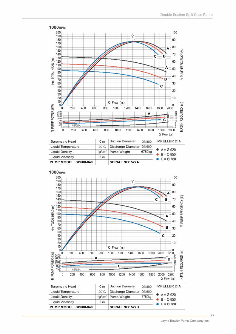
77
0102030405060708090
100110120130140150160170180190200
0 200 400 600 800 1000 1200 1400 1600 1800 2000 22000
10
20
30
40
50
60
70
80
90
100
0400800
1200160020002400
04812162024
A
B
C
A B
C
A
B
C
0 200 400 600 800 1000 1200 1400 1600 1800 2000 2200
N.P
.S.H
. RE
QU
IRE
D (
m)
N P
UM
P P
OW
ER
(kW
)H
m T
OTA
L H
EA
D (m
)
P
UM
P E
FFIC
IEN
CY
(%)
1000RPM
0102030405060708090
100110120130140150160170180190200
0 200 400 600 800 1000 1200 1400 1600 1800 20000
10
20
30
40
50
60
70
80
90
100
A
B
C
A
B
C
0400800
12001600200024002800
0481216202428
AB
C
0 200 400 600 800 1000 1200 1400 1600 1800 2000
Hm
TO
TAL
HE
AD
(m)
N P
UM
P P
OW
ER
(kW
)
N.P
.S.H
. RE
QU
IRE
D (
m)
P
UM
P E
FFIC
IEN
CY
(%)
1000RPM
Q Flow (l/s)
Q Flow (l/s)
B = Ø 850A = Ø 920
C = Ø 780
6750kg
DN800
DN600
0 m
20°C31g/cm
D�scharge D�ameter
Pump We�ght
SERIAL NO: 527B
L�qu�d V�scos�ty
PUMP MODEL: SP600-840
Barometr�c Head
L�qu�d Temperature
L�qu�d Dens�ty
Suct�on D�ameter IMPELLER DIA
1 cs
B = Ø 850A = Ø 920
C = Ø 780
6750kg
DN800
DN600
0 m
20°C31g/cm
D�scharge D�ameter
Pump We�ght
SERIAL NO: 527A
L�qu�d V�scos�ty
PUMP MODEL: SP600-840
Barometr�c Head
L�qu�d Temperature
L�qu�d Dens�ty
Suct�on D�ameter IMPELLER DIA
1 cs
N.P.S.H.
N.P.S.H.
Q Debi (l/s)Q Flow (l/s)
Q Flow (l/s)
Layne Bowler Pump Company Inc.
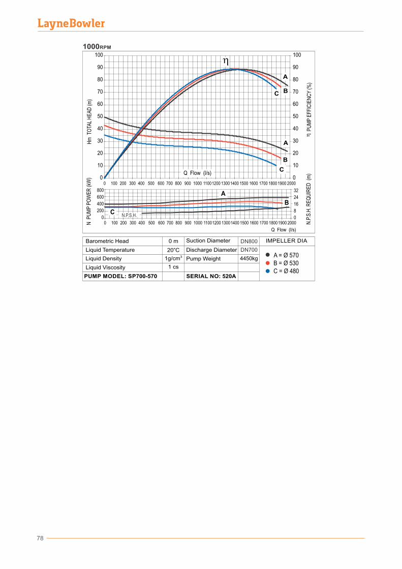
78
0
10
20
30
40
50
60
70
80
90
100
0
10
20
30
40
50
60
70
80
90
100
A
B
C
A
B
C
Hm
TO
TAL
HE
AD
(m)
N P
UM
P P
OW
ER
(kW
)
N.P
.S.H
. RE
QU
IRE
D (
m)
P
UM
P E
FFIC
IEN
CY
(%)
1000RPM
0 100 200 300 400 500 600 700 800 900 1000 11001200 13001400 1500 1600 1700 1800 1900 2000
0
200
400
600
800
0
8
16
24
32A
B
C
0 100 200 300 400 500 600 700 800 900 1000 11001200 13001400 1500 1600 1700 1800 1900 2000
Q Flow (l/s)
B = Ø 530A = Ø 570
C = Ø 480
4450kg
DN800
DN700
0 m
20°C31g/cm
D�scharge D�ameter
Pump We�ght
SERIAL NO: 520A
L�qu�d V�scos�ty
PUMP MODEL: SP700-570
Barometr�c Head
L�qu�d Temperature
L�qu�d Dens�ty
Suct�on D�ameter IMPELLER DIA
1 cs
N.P.S.H.
Q Flow (l/s)
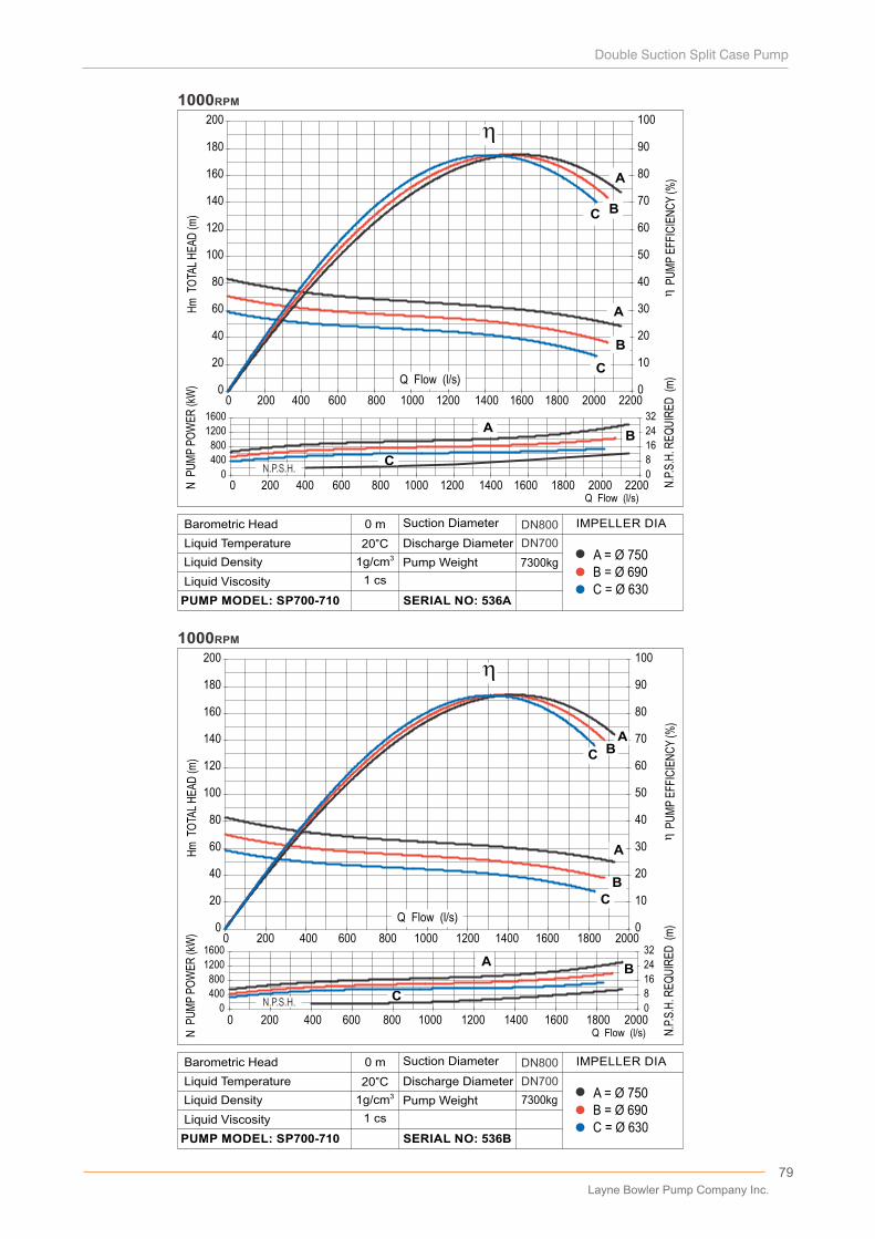
79
0
20
40
60
80
100
120
140
160
180
200
0 200 400 600 800 1000 1200 1400 1600 1800 2000 22000
10
20
30
40
50
60
70
80
90
100
A
B
C
A
B
C
1000RPM
0
400
800
1200
1600
0
8
16
24
32A
B
0 200 400 600 800 1000 1200 1400 1600 1800 2000 2200
Hm
TO
TAL
HE
AD
(m)
N P
UM
P P
OW
ER
(kW
)
N.P
.S.H
. RE
QU
IRE
D (
m)
P
UM
P E
FFIC
IEN
CY
(%)
0
20
40
60
80
100
120
140
160
180
200
0 200 400 600 800 1000 1200 1400 1600 1800 20000
10
20
30
40
50
60
70
80
90
100
A
B
C
AB
C
1000RPM
N.P
.S.H
. RE
QU
IRE
D (
m)
0
400
800
1200
1600
0
8
16
24
32A
B
C
0 200 400 600 800 1000 1200 1400 1600 1800 2000
N P
UM
P P
OW
ER
(kW
)H
m T
OTA
L H
EA
D (m
)
P
UM
P E
FFIC
IEN
CY
(%)
C
Q Flow (l/s)
Q Flow (l/s)
Q Flow (l/s)
B = Ø 690A = Ø 750
C = Ø 630
7300kg
DN800
DN700
0 m
20°C31g/cm
D�scharge D�ameter
Pump We�ght
SERIAL NO: 536B
L�qu�d V�scos�ty
PUMP MODEL: SP700-710
Barometr�c Head
L�qu�d Temperature
L�qu�d Dens�ty
Suct�on D�ameter IMPELLER DIA
1 cs
B = Ø 690A = Ø 750
C = Ø 630
7300kg
DN800
DN700
0 m
20°C31g/cm
D�scharge D�ameter
Pump We�ght
SERIAL NO: 536A
L�qu�d V�scos�ty
PUMP MODEL: SP700-710
Barometr�c Head
L�qu�d Temperature
L�qu�d Dens�ty
Suct�on D�ameter IMPELLER DIA
1 cs
N.P.S.H.
N.P.S.H.
Q Flow (l/s)
Layne Bowler Pump Company Inc.
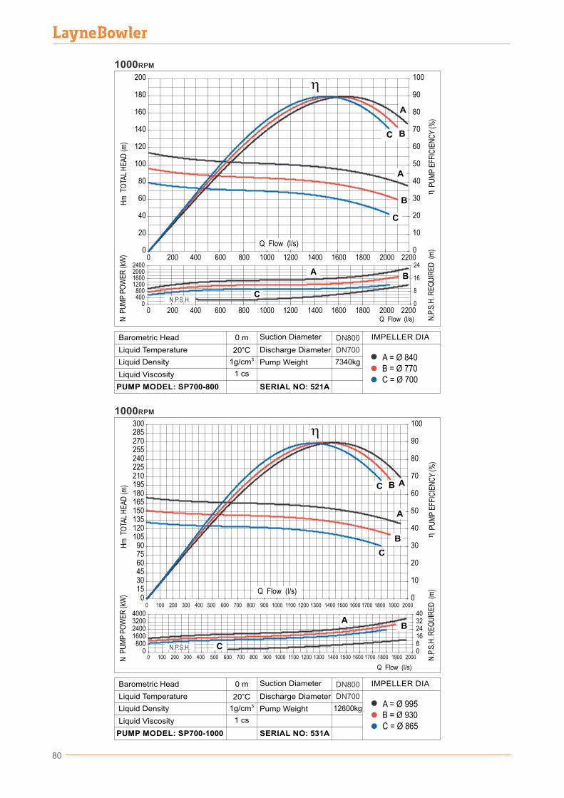
80
0
20
40
60
80
100
120
140
160
180
200
0
10
20
30
40
50
60
70
80
90
100
A
B
C
A
0 200 400 600 800 1000 1200 1400 1600 1800 2000 22000
400800
1200160020002400
0
8
16
24A
B
C
B
C
0 200 400 600 800 1000 1200 1400 1600 1800 2000 2200
N P
UM
P P
OW
ER
(kW
)H
m T
OTA
L H
EA
D (m
)
...
N.P
.S.H
. RE
QU
IRE
D (
m)
P
UM
P E
FFIC
IEN
CY
(%)
1000RPM
0153045607590
105120135150165180195210225240255270285300
0 100 200 300 400 500 600 700 800 900 1000 1100 1200 1300 1400 1500 1600 1700 1800 1900 20000
10
20
30
40
50
60
70
80
90
100
A
B
C AB
C
1000RPM
0800
1600240032004000
0816243240
AB
C0 100 200 300 400 500 600 700 800 900 1000 1100 1200 1300 1400 1500 1600 1700 1800 1900 2000
Hm
TO
TAL
HE
AD
(m)
N P
UM
P P
OW
ER
(kW
)
N.P
.S.H
. RE
QU
IRE
D (
m)
P
UM
P E
FFIC
IEN
CY
(%)
N.P.S.H.
N.P.S.H.
Q Debi (l/s)
Q Flow (l/s)
Q Flow (l/s)
B = Ø 930A = Ø 995
C = Ø 865
12600kg
DN800
DN700
B = Ø 770A = Ø 840
C = Ø 700
7340kg
DN800
DN700
0 m
20°C31g/cm
D�scharge D�ameter
Pump We�ght
SERIAL NO: 521A
L�qu�d V�scos�ty
PUMP MODEL: SP700-800
Barometr�c Head
L�qu�d Temperature
L�qu�d Dens�ty
Suct�on D�ameter IMPELLER DIA
1 cs
0 m
20°C31g/cm
D�scharge D�ameter
Pump We�ght
SERIAL NO: 531A
L�qu�d V�scos�ty
PUMP MODEL: SP700-1000
Barometr�c Head
L�qu�d Temperature
L�qu�d Dens�ty
Suct�on D�ameter IMPELLER DIA
1 cs
Q Flow (l/s)
Q Flow (l/s)
81
PerformanceCurves
750rpm
Layne Bowler Pump Company Inc.

82
B = Ø 840A = Ø 900
C = Ø 780
9400kg
DN800
DN900
0 m
20°C31g/cm
D�scharge D�ameter
Pump We�ght
SERIAL NO: 533A
L�qu�d V�scos�ty
PUMP MODEL: SP800-850
Barometr�c Head
L�qu�d Temperature
L�qu�d Dens�ty
Suct�on D�ameter IMPELLER DIA
1 cs
B = Ø 750A = Ø 850
C = Ø 650
8520kg
DN800
DN900
0 m
20°C31g/cm
D�scharge D�ameter
Pump We�ght
SERIAL NO: 532A
L�qu�d V�scos�ty
PUMP MODEL: SP800-740
Barometr�c Head
L�qu�d Temperature
L�qu�d Dens�ty
Suct�on D�ameter IMPELLER DIA
1 cs
0
10
20
30
40
50
60
70
80
90
100
0
10
20
30
40
50
60
70
80
90
100
0200400600800
1000
0 250 500 750 1000 1250 1500 1750 2000 2250 250001020304050
AB
CA
750RPM
0 250 500 750 1000 1250 1500 1750 2000 2250 2500
N.P
.S.H
. RE
QU
IRE
D (
m)
P
UM
P E
FFIC
IEN
CY
(%)
N P
UM
P P
OW
ER
(kW
)H
m T
OTA
L H
EA
D (m
)
A
B
CAB
C
N.P.S.H.
0
10
20
30
40
50
60
70
80
90
100
0
10
20
30
40
50
60
70
80
90
100
0200400600800
10001200140016001800
0 250 500 750 1000 1250 1500 1750 2000 2250 2500 27500
8
16
24
32
A
B
C
AB
C
A
B
C
750RPM
0 250 500 750 1000 1250 1500 1750 2000 2250 2500 2750
Hm
TO
TAL
HE
AD
(m)
N P
UM
P P
OW
ER
(kW
)
N.P
.S.H
. RE
QU
IRE
D (
m)
P
UM
P E
FFIC
IEN
CY
(%)
N.P.S.H.
Q Flow (l/s)
Q Flow (l/s)
Q Flow (l/s)
Q Flow (l/s)
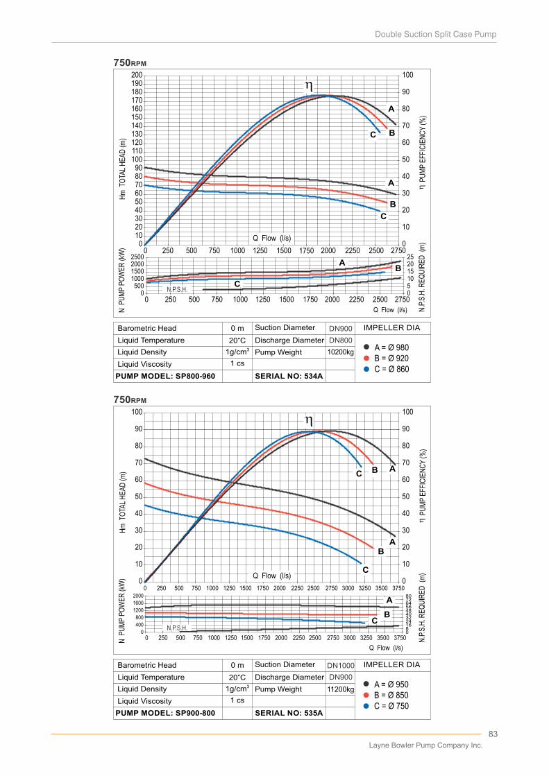
83
0
10
20
30
40
50
60
70
80
90
100
0 250 500 750 1000 1250 1500 1750 2000 2250 2500 2750 3000 3250 3500 37500
10
20
30
40
50
60
70
80
90
100
AB
CAB
C
750RPM
0
400
800
1200
1600
2000
08162432404856647280
A
BC
0 250 500 750 1000 1250 1500 1750 2000 2250 2500 2750 3000 3250 3500 3750
Hm
TO
TAL
HE
AD
(m)
N P
UM
P P
OW
ER
(kW
)
N.P
.S.H
. RE
QU
IRE
D (
m)
P
UM
P E
FFIC
IEN
CY
(%)
0102030405060708090
100110120130140150160170180190200
0 250 500 750 1000 1250 1500 1750 2000 2250 2500 27500
10
20
30
40
50
60
70
80
90
100
A
B
C
A
B
C
750RPM
0500
1000150020002500
0510152025
AB
C
0 250 500 750 1000 1250 1500 1750 2000 2250 2500 2750
N.P
.S.H
. RE
QU
IRE
D (
m)
P
UM
P E
FFIC
IEN
CY
(%)
N P
UM
P P
OW
ER
(kW
)H
m T
OTA
L H
EA
D (m
)
Q Flow (l/s)
Q Flow (l/s)
Q Flow (l/s)
B = Ø 850A = Ø 950
C = Ø 750
11200kg
DN1000
DN900
0 m
20°C31g/cm
D�scharge D�ameter
Pump We�ght
SERIAL NO: 535A
L�qu�d V�scos�ty
PUMP MODEL: SP900-800
Barometr�c Head
L�qu�d Temperature
L�qu�d Dens�ty
Suct�on D�ameter IMPELLER DIA
1 cs
B = Ø 920A = Ø 980
C = Ø 860
10200kg
DN800
DN900
0 m
20°C31g/cm
D�scharge D�ameter
Pump We�ght
SERIAL NO: 534A
L�qu�d V�scos�ty
PUMP MODEL: SP800-960
Barometr�c Head
L�qu�d Temperature
L�qu�d Dens�ty
Suct�on D�ameter IMPELLER DIA
1 cs
N.P.S.H.
N.P.S.H.
Q Flow (l/s)
Layne Bowler Pump Company Inc.
PerformanceCurves
600rpm
84
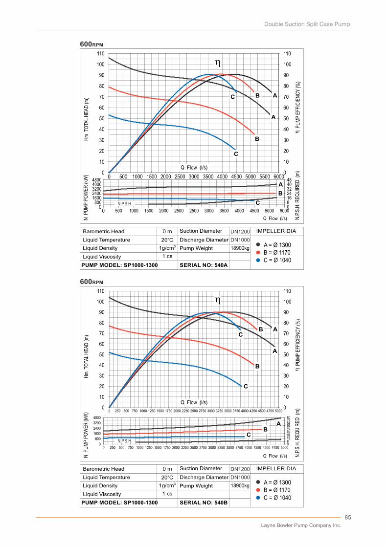
85
Q Flow (l/s)
Q Flow (l/s)
B = Ø 1170A = Ø 1300
C = Ø 1040
18900kg
DN1000
DN1200
0 m
20°C31g/cm
D�scharge D�ameter
Pump We�ght
SERIAL NO: 540B
L�qu�d V�scos�ty
PUMP MODEL: SP1000-1300
Barometr�c Head
L�qu�d Temperature
L�qu�d Dens�ty
Suct�on D�ameter IMPELLER DIA
1 cs
18900kg
DN1000
DN1200
600RPM
600RPM
80016002400320040004800
0
168
24324048
00
N.P
.S.H
. RE
QU
IRE
D (
m)
P
UM
P E
FFIC
IEN
CY
(%)
N P
UM
P P
OW
ER
(kW
)H
m T
OTA
L H
EA
D (m
)
600055005000450040002500 3000 35002000150010005000
60005000450040003500300025002500200015001000500
100
110
0
10
20
30
40
50
60
70
80
90
100
110
0
10
20
30
40
50
60
70
80
90
800
1600
2400
3200
4000 807264564840322416800
N.P
.S.H
. RE
QU
IRE
D (
m)
P
UM
P E
FFIC
IEN
CY
(%)
N P
UM
P P
OW
ER
(kW
)H
m T
OTA
L H
EA
D (m
)
500047504500425040003250 3500 37503000275025002250200017501500125010007505002500
100
110
0
10
20
30
40
50
60
70
80
90
100
110
0
10
20
30
40
50
60
70
80
90
AB
A
B
C
C
500047504500425040003250 3500 37503000275025002250200017501500125010007505002500
ABC
B
C
AB
C
A
B
C
A
N.P.S.H.
N.P.S.H.
B = Ø 1170A = Ø 1300
C = Ø 1040
0 m
20°C31g/cm
D�scharge D�ameter
Pump We�ght
SERIAL NO: 540A
L�qu�d V�scos�ty
PUMP MODEL: SP1000-1300
Barometr�c Head
L�qu�d Temperature
L�qu�d Dens�ty
Suct�on D�ameter IMPELLER DIA
1 cs
Q Flow (l/s)
Q Flow (l/s)
Layne Bowler Pump Company Inc.
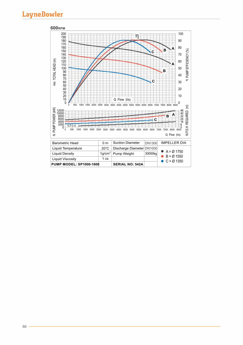
86
B = Ø 1550A = Ø 1750
C = Ø 1350
30000kg
DN1000
DN1300
0 m
20°C31g/cm
D�scharge D�ameter
Pump We�ght
SERIAL NO: 542A
L�qu�d V�scos�ty
PUMP MODEL: SP1000-1600
Barometr�c Head
L�qu�d Temperature
L�qu�d Dens�ty
Suct�on D�ameter IMPELLER DIA
1 cs
600RPM
2000400060008000
1000012000
0
168
24324048
0
N.P
.S.H
. RE
QU
IRE
D (
m)
P
UM
P E
FFIC
IEN
CY
(%)
N P
UM
P P
OW
ER
(kW
)H
m T
OTA
L H
EA
D (m
)
850080007500700065005000 5500 60004500400035003000
100
0
10
20
30
40
50
60
70
80
90
200
0
110100
908070605040302010
120130140150160170180190
25002000150010005000
850080007500700065005000 5500 6000450040003500300025002000150010005000
ABC
A
B
C
ABC
N.P.S.H.
Q Flow (l/s)
Q Flow (l/s)
WARRANTY
Warranty Duration: All Layne Bowler Pump Company products are guarantied for 12 months from taking them into operation or 18 months from the shipping date, whichever comes first.
End-user Responsibilities: Warranty service must be performed by an authorized service. If the End-user is unable to locate or obtain warranty service from any Authorized Services or Representatives, he should call the factory at the given number and ask for the After Sales Department, which will then arrange him a special warranty service.
Warranty service will be performed during normal working hours.
The end-user must present his Warranty Certificate together with the product invoice upon request.
The end-user is responsible for normal care.
This warranty only applies to officially and accepted claims breakdowns, it does not cover any defect, malfunction, etc. resulting from misuse, abuse, lack of normal care, corrosion, freezing, modification, unauthorized or improper repair or installation, accident, acts of nature or any other application done contrary to Layne Bowler Pump Company Installation, Operation and Maintenance Manual.
Limitations And Exclusions: If any Layne Bowler part is repaired or replaced, the new part shall be warranted for only the remainder of the original warranty period.
Warranty Claims should be well explained and accompanied with photos and transferred to Layne Bowler Pump Company Inc. within a maximum of one week (5 working days) including the day of breakdown. Otherwise this breakdown will be considered immediately out of warranty.
Consequential damages, due to unclaimed failure(s) or problem(s) observed during operation are not covered by this warranty.
No claim may be made against Layne Bowler Pump Company products based on any oral warranty.
The end-user should take all necessary precaution against any breakdown or failure in Layne Bowler Pump Company product. Lost profits, delay or any other loss due to unavailability of Layne Bowler Pump Company Inc. products during failure or reparation is out of Layne Bowler Pump Company Inc. responsibility.
87
Layne Bowler Pump Company Inc.
88
NECESSARY INFORMATION FOR INQUIRY
Below details will help us to offer the most proper alternative for your needs.
3Required capacity, Q : l/s or m /h Required total manometric head, Hm : m Speed : rpm Liquid type : Viscosity :
Horizontal or verticalPump installation type : Site altitude : Pump elevation level from water level : Casing material : Impeller material : Motor starting type : With variable speed drive, soft starter,
direct
Voltage : Frequency :
Motor isolation class : Motor cooling type :
Ambient temperature :
Batı S�tes� Mah. F.S.M. Bulvarı No: 546 06370 Yen�mahalle - Ankara / TURKEYTel: +90 312 255 96 51 • Fax: +90 312 255 96 50
www.laynebowler.com.tr • [email protected]
LAYNE BOWLER POMPA SANAYİ A.S. / LAYNE BOWLER PUMP COMPANY INC.


![Whitney Layne Scored[1]](https://img.pdfslide.us/doc/110x75/577d239a1a28ab4e1e9a419f/whitney-layne-scored1.jpg)


![Layne Norton Frequently Asked Questions[1]](https://img.pdfslide.us/doc/110x75/55cf9a6c550346d033a1a2d2/layne-norton-frequently-asked-questions1.jpg)